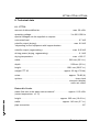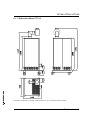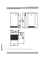
1
Operating Instructions
Dehumidified air dryer
CTT 30
CTT 60
CTT 120
Colortronic GmbH
CTT 30 / CTT 60 / CTT 120
Colortronic GmbH
Otto-Hahn-Straße 10-14
D-61381 Friedrichsdorf
USA
Colortronic, Inc.
VPR Commerc Center, Suite 406/407
1001 Lower Landing Road
Blackwood, NJ 08012
Telephone (0 61 75) 7 92-0
Telefax (0 61 75) 7 92-1 79
Email [email protected]
Telephone (609) 374-9200
Telefax (609) 374-9311
Email [email protected]
Technical service:
Service department
Telephone: (0 61 75) 7 92-2 22
Telefax: (0 61 75) 7 92-1 19
Email [email protected]
Spare parts department
Telephone: (0 61 75) 7 92-3 33
Telefax: (0 61 75) 7 92-1 08
Edition: 06/98
Order number: 64.10-0076GB01A
These operating instructions are for*:
(* Please fill in personally)
Serial number:
Built in:
Date of delivery:
Number of delivery:
Date of commissioning:
Location:
Group of machines:
2
CTT 30 / CTT 60 / CTT 120
Colortronic GmbH retains all rights to change the information in these operating
instructions at any time without notice.
We assume no liability for any errors or direct or indirect damage resulting in context with these operating instructions.
Copying, translation or publication in any form except for personal use of purchaser requires approval from Colortronic GmbH.
All rights reserved.
3
CTT 30 / CTT 60 / CTT 120
Table of contents
1. Safety instructions . . . . . . . . . . . . . . . . . . . . . . . . . . . . . . . . . . . . . . . . . . . . 6
1.1.
1.2.
1.3.
1.4.
Warnings and symbols . . . . . . . . . . . . . . . . . . . . . . . . . . . . . . . . . . 7
Explanations and information . . . . . . . . . . . . . . . . . . . . . . . . . . . . . 8
For your safety . . . . . . . . . . . . . . . . . . . . . . . . . . . . . . . . . . . . . . . . . 9
For the Safety of the Devices . . . . . . . . . . . . . . . . . . . . . . . . . . . . 13
2. Assembly instructions . . . . . . . . . . . . . . . . . . . . . . . . . . . . . . . . . . . . . . . . 15
2.1.
2.2.
2.3.
2.4.
2.5.
Transport . . . . . . . . . . . . . . . . . . . . . . . . . . . . . . . . . . . . . . . . . . . . 17
Installation . . . . . . . . . . . . . . . . . . . . . . . . . . . . . . . . . . . . . . . . . . . 18
Installation of the exhauster fan for regeneration of exhaust air 19
Electrical Connection. . . . . . . . . . . . . . . . . . . . . . . . . . . . . . . . . . . 20
Connection of Return Air Cooler (Optional) . . . . . . . . . . . . . . . . . 21
3. Functional description . . . . . . . . . . . . . . . . . . . . . . . . . . . . . . . . . . . . . . . . 22
3.1. General Information. . . . . . . . . . . . . . . . . . . . . . . . . . . . . . . . . . . . 23
3.2. Drying Hopper (Optional) . . . . . . . . . . . . . . . . . . . . . . . . . . . . . . . 25
3.2.1. Hopper Heater . . . . . . . . . . . . . . . . . . . . . . . . . . . . . . . . 26
3.3. Connection to a Pneumatic Conveying System. . . . . . . . . . . . . . 27
3.4. Return Air Cooler (Optional) . . . . . . . . . . . . . . . . . . . . . . . . . . . . . 28
3.5. Timer Clock (Optional) . . . . . . . . . . . . . . . . . . . . . . . . . . . . . . . . . 28
4. Start up . . . . . . . . . . . . . . . . . . . . . . . . . . . . . . . . . . . . . . . . . . . . . . . . . . . . . 29
4.1. Initial Operation . . . . . . . . . . . . . . . . . . . . . . . . . . . . . . . . . . . . . . . 30
4.1.1. Switching on the Dryer . . . . . . . . . . . . . . . . . . . . . . . . . 30
4.1.2. Setting the Drying Temperature . . . . . . . . . . . . . . . . . . 31
4.2. Continuous Operation . . . . . . . . . . . . . . . . . . . . . . . . . . . . . . . . . . 32
4.2.1. Switching the Dryer on . . . . . . . . . . . . . . . . . . . . . . . . . 32
4.2.2. Setting the Drying Temperature . . . . . . . . . . . . . . . . . . 33
4.3. Switching the Dryer off . . . . . . . . . . . . . . . . . . . . . . . . . . . . . . . . . 34
4.4. Alarm Messages . . . . . . . . . . . . . . . . . . . . . . . . . . . . . . . . . . . . . . 35
Table of contents 4
CTT 30 / CTT 60 / CTT 120
5. Maintenance . . . . . . . . . . . . . . . . . . . . . . . . . . . . . . . . . . . . . . . . . . . . . . . . . 36
5.1. Maintenance schedule . . . . . . . . . . . . . . . . . . . . . . . . . . . . . . . . . 38
5.2. Cleaning or Replacing the Air Filter . . . . . . . . . . . . . . . . . . . . . . . 39
5.2.1. Cleaning or Replacing the Return Air Filter . . . . . . . . . 40
5.2.2. Cleaning or Replacing the Air Filter of the Suction
Box (Optional) . . . . . . . . . . . . . . . . . . . . . . . . . . . . . . . . 42
5.3. Disposing of Drying Agents. . . . . . . . . . . . . . . . . . . . . . . . . . . . . . 43
5.4. Checking the Signal Lamps . . . . . . . . . . . . . . . . . . . . . . . . . . . . . 44
5.4.1. Replacing the Bulb of the Signal Lamp . . . . . . . . . . . . 44
5.5. Cleaning the Drying Hopper . . . . . . . . . . . . . . . . . . . . . . . . . . . . . 46
6. Technical data . . . . . . . . . . . . . . . . . . . . . . . . . . . . . . . . . . . . . . . . . . . . . . . 48
6.1. CTT 30 . . . . . . . . . . . . . . . . . . . . . . . . . . . . . . . . . . . . . . . . . . . . . . 48
6.1.1. Dimension Sheet CTT 30 . . . . . . . . . . . . . . . . . . . . . . . 49
6.2. CTT 60 . . . . . . . . . . . . . . . . . . . . . . . . . . . . . . . . . . . . . . . . . . . . . . 50
6.2.1. Dimension Sheet CTT 60 . . . . . . . . . . . . . . . . . . . . . . . 51
6.3. CTT 120 . . . . . . . . . . . . . . . . . . . . . . . . . . . . . . . . . . . . . . . . . . . . . 52
6.3.1. Dimension Sheet CTT 120 . . . . . . . . . . . . . . . . . . . . . . 53
7. Annex . . . . . . . . . . . . . . . . . . . . . . . . . . . . . . . . . . . . . . . . . . . . . . . . . . . . . . 54
7.1. Spare parts list. . . . . . . . . . . . . . . . . . . . . . . . . . . . . . . . . . . . . . . . 55
7.1.1. Parts list CTT 30 . . . . . . . . . . . . . . . . . . . . . . . . . . . . . . 56
7.1.2. Parts list CTT 60 . . . . . . . . . . . . . . . . . . . . . . . . . . . . . . 59
7.1.3. Parts list CTT 120 . . . . . . . . . . . . . . . . . . . . . . . . . . . . . 62
7.2. Electrical manual . . . . . . . . . . . . . . . . . . . . . . . . . . . . . . . . . . . . . . 65
Table of contents 5
CTT 30 / CTT 60 / CTT 120
1. Safety instructions
»
These safety instructions apply to all persons within the range of
action of the equipment.
Please inform all persons within the range of action of the equipment of the direct and indirect hazards connected with the
equipment.
These operating instructions are to be used by all persons assigned activities connected with the equipment.
Knowledge of the English language is prerequisite.
Ensure in each case that the operating personnel are familiar
with the operating instructions and the function of the equipment.
Safety instructions 6
CTT 30 / CTT 60 / CTT 120
1.1. Warnings and symbols
The following warnings and symbols are used in these operating instructions:
»
This symbol indicates danger to life! Fatal or serious injury is
possible if the corresponding instructions, regulations or warnings are not observed.
L
This symbol indicates that serious injury is possible if the corresponding instructions, regulations or warnings are not observed.
F
This symbol indicates that extensive damage to equipment is
possible if the corresponding instructions, regulations or
warnings are not observed.
&
This symbol indicates information important for becoming familiar with the equipment, i.e. technical correlations.
$
This symbol indicates that a technical term is explained at
this point.
Safety instructions 7
CTT 30 / CTT 60 / CTT 120
1.2. Explanations and information
Various terms and designations are used in these operating instructions to ensure clarity. Therefore please note that the terms used in the text stand for the
corresponding explanations listed below.
ment
• Equip
“Equipment” can mean an individual unit, a machine or an installation.
erating personnel
• Op
The “operating personnel” are persons operating the equipment on their own responsibility or according to instructions.
erator
• Op
The “operator” of the equipment (production manager, foreman, etc.) is the person responsible for all production sequences. The operator instructs the operating personnel of what is to be done.
erating instructions
• Op
The “operating instructions” describe the interaction of the equipment, production
sequences or methods. The operating instructions must be compiled by the operator of the equipment.
ment foreman
• Equip
When several operating personnel work on one machine, the “equipment foreman” coordinates the sequences. The equipment foreman must be appointed by
the operator.
personnel
• Trained
“Trained personnel” are persons who, due to their training, are authorized to carry
out the required work.
Safety instructions 8
CTT 30 / CTT 60 / CTT 120
1.3. For your safety
• The operator of this machine must be at least 16 years old.
these operating instructions carefully before the initial start-up. Observe all
• Read
points. Contact us if anything is unclear.
This avoids injury and damage to equipment!
instructions must be stored in such a way that they are available at all times
• These
at the place of operation of the machine.
Danger of accidents arising through improper use!
note that for reasons of clarity not every conceivable case of operation or
• Please
of maintenance can betaken into consideration.
serve all safety and hazard warnings on the equipment.
• Ob
This avoids injury and damage!
low all work on the machine to be carried out only by persons whose qualifica• Altions
are set out in the relevant chapters of the operating instructions.
Danger of accidents from improper use!
all work carried out on the equipment only the prescribed working clothes
• For
should be worn.
This avoids injury!
pare the electric supply values with those of the mains supply.
• Com
Danger of accidents from electric shock!
using lifting gear, please observe the relevant regulations.
• When
Danger of accidents!
note that all installation, start-up and maintenance work is to be carried out
• Please
only by qualified, trained staff.
Danger of accidents from improper use!
Safety instructions 9
CTT 30 / CTT 60 / CTT 120
local regulations and requirements pertaining to the equipment must be ob• The
served.
“5 safety rules” as provided in DIN VDE 0105, Section 1, must be observed
• The
for all work carried out on the equipment.
connect electrical components from the mains supply before work is carried
• Dis
out on these components.
Danger to life and limb from electric shock!
not modify, add other equipment or change the design of the equipment with• Do
out the approval of the manufacturer.
Danger of accidents!
pile detailed operating instructions based on the operating instructions sup• Com
plied for the sequence of procedures to be carried out on this machine.
Danger of accidents from improper use!
• Appoint a machine foreman to be responsible for the machine.
sure that the operating staff are thoroughly trained in the operation of the
• En
equipment.
Danger of accidents from improper use!
the machine is switched off for safety reasons, it must be secured against un• Ifauthor
ised activation.
Danger of accidents!
• Before starting maintenance work, appoint a supervisor.
form the staff responsible before starting maintenance work.
• InDan
ger of accidents!
connect the equipment from the mains supply before starting maintenance
• Dis
work to ensure that it cannot be switched on accidentally.
Danger of accidents!
Safety instructions 10
CTT 30 / CTT 60 / CTT 120
pair work may be carried out only by trained staff!
• Re
Danger of accidents!
operate the equipment when it is partly dismantled!
• Never
Danger! Limbs may be caught in machinery! Electric shock!
machine may only be operated when all the associated components are
• The
properly connected up and in accordance with the relevant regulations.
case of malfunction, shut down the equipment immediately. Have faults cor• Inrected
immediately.
Danger of accidents!
machine is intended only for the drying of granulated plastics. Any other or
• The
additional use is contrary to specifications.
• This machine is not suitable for food-drying.
note that sound levels exceeding 85 db(A) may in the long term damage
• Please
your health. Use the appropriate ear muffs.
This avoids impairment of hearing!
ments not supplied by Colortronic must be manufactured in accordance
• Atwithtachsafety
regulation EN 294.
Danger of accidents!
pipes, hoses and screwed connections should be checked regularly for leaks
• All
and damage. Any faults which arise should be corrected immediately.
Danger of accidents!
• The safety instructions of the connected machines must be followed.
return air filter should only be cleaned/replaced when the the main switch is
• The
off and the blower has stopped.
This avoids injury and damage to equipment!
Safety instructions 11
CTT 30 / CTT 60 / CTT 120
operate the dryer without side panels.
• Never
Danger: Limbs may be caught in machinery! Injury through burns!
drying plastics which emit gases dangerous for human health, take care
• When
that the regeneration exhaust air is disposed of without polluting the environment.
• Open drying hoppers only if they are completely empty.
open drying hoppers while the device is in operation.
• Never
Danger: Iinjury through burns!
drying hoppers only if they have been cooled down sufficiently.
• Open
Danger: Injury through burns!
move any granules remaining on the ground.
• Re
Danger of accidents!
rest the wheels after installation if the dryer is mounted on a movable frame.
• Ar
This will prevent danger to people and material!
care that the device is not standing on the mains cable.
• Take
This will prevent danger to people and material!
note that the drying cells, drying hoppers and air pipings grow hot during
• Please
use. Avoid touching any of these parts!
Danger: Injury through burns!
erate the dryer only if there is at least one drying hopper operating.
• Op
This will prevent damage of material!
Safety instructions 12
CTT 30 / CTT 60 / CTT 120
1.4. For the Safety of the Devices
• Never change settings without carefully assessing the consequences.
• Use only original Colortronic spare parts.
• Observe the maintenance instructions.
• Keep a record of all maintenance works and repairs.
• Please note that electronic components can be damaged by static discharge.
fore initial operation and in regular intervals, make sure that no electrical con• Be
nections are loose.
• Never readjust sensors without exactly knowing their functions.
• Please note that the maximum ambient temperature may not exceed +35 °C.
• Clean the drying hoppers before the first filling.
the instructions of the material manufacturer for the maximum drying tem• Note
perature.
• Note the drying instructions of the material manufacturer.
care that the drying hoppers are always completely filled and that the reten• Take
tion period is respected if continual removal is taking place.
that too large amounts taken from the drying hopper lead to insufficient dry• Note
ing of the material.
the air stop valves of drying hoppers which are empty or have not been
• Close
used.
Safety instructions 13
CTT 30 / CTT 60 / CTT 120
• Note down all data which you have entered into the control system.
• When you dispose of drying agents, observe all official rules.
• Note that drying cells are replaced or refilled by Colortronic only if they are empty.
• Note that the dryer may be neither tipped nor laid on its side.
or replace the return air filter only if the main switch is switched off and the
• Clean
blower has stopped.
• Operate the device only if the drying hopper is sufficiently filled with material.
• Operate the device only if at least one drying hopper is operating.
• Read the operating manuals of the connected devices.
Safety instructions 14
CTT 30 / CTT 60 / CTT 120
2. Assembly instructions
»
These installation instructions are intended for persons with
skills in electrical and mechanical areas due to their training, experience and received instructions.
Personnel using these installation instructions must be
instructed in the regulations for the prevention of accidents, the
operating conditions and safety regulations and their
implementation.
Ensure in each case that the personnel are informed.
The installation instructions provided in the corresponding operating instructions apply for all connected equipment.
Observe safety regulations with regard to lifting gear handling.
All installation work must be carried out with the equipment disconnected from electrical power and compressed air supply.
L
For installation work taking place at heights of over approx. 6
feet, use only ladders or similar equipment and working platforms intended for this purpose. At greater heights, the
proper equipment for protection against falling must be worn.
Use only suitable and technically sound lifting equipment and
load suspension devices with sufficient carrying force. Do not
stand or work under suspended loads!
Use suitable workshop equipment.
Assembly instructions 15
CTT 30 / CTT 60 / CTT 120
F
Install the equipment such that all parts are easily
accessible; this facilitates maintenance and repair work.
Assembly instructions 16
CTT 30 / CTT 60 / CTT 120
2.1. Transport
The dryer or the compact unit is delivered on a pallet.
The dryer should only be moved by means of the appropriate lifting equipment
(e.g. a fork lift).
»
Attention should be paid to the load capacity of the lifting equipment.
All safety regulations regarding work with lifting equipment
should be obeyed.
F
The machine must not be tilted or laid on its side.
Assembly instructions 17
CTT 30 / CTT 60 / CTT 120
2.2. Installation
Because of its compact construction the dryer can be installed directly beside the
processing machine (drying hopper on the processing machine) or supplied with
a drying hopper as a mobile attachment (compact unit).
Special foundations are not necessary for installation.
The dryer must be installed on a level surface and must not be exposed to excessive humidity. The maximum permissible ambient temperature is 35 °C.
To facilitate servicing, the dryer should be installed in such a way that that it is accessible from 3 sides.
»
F
The main switch must be freely accessible.
The equipment must not be tilted or laid on its side.
To conserve energy, keep the distance between dryer, hopper and processing
machine as small as possible.
The wheels of the compact unit should be locked to ensure stable installation.
The foil should be removed from the drying hopper.
Assembly instructions 18
CTT 30 / CTT 60 / CTT 120
2.3. Installation of the exhauster fan for regeneration of exhaust air
When plastics are being dried that release harmful gases during the drying process, care must be taken that the regeneration exhaust air is disposed of in an environmentally sound way. At the same time the throughput of the regeneration
blower must not be altered. It should be noted when assembling a disposal system (e.g. an exhauster system) that the regeneration exhaust air is very humid.
Thus condensation may form, which must not under any circumstances return to
the dryer.
Assembly instructions 19
CTT 30 / CTT 60 / CTT 120
2.4. Electrical Connection
»
The electrical connection of the dryer and of the hopper heaters
may only be carried through or assigned by
Colortronic service staff or by qualified staff authorized by
Colortronic.
Other persons are not permitted to carry through the
electrical connection.
Observe the rules of the local electricity board.
F
Regularly make sure that none of the electrical or screw connections are loose.
The operating voltage is 400 V/50 Hz, 3 AC or 400 V/60 Hz, 3 AC.
Special voltages can be supplied on request.
The connected loads are
CTT 30 . . . . . . . . . . . . . . . . . . . . . . . . . . . . . . . . . . . . . . . . . . . . approx. 0.7 kW;
CTT 60 . . . . . . . . . . . . . . . . . . . . . . . . . . . . . . . . . . . . . . . . . . . approx. 1.6 kW;
CTT 120 . . . . . . . . . . . . . . . . . . . . . . . . . . . . . . . . . . . . . . . . . . . approx. 3.2 kW.
If hopper heaters are installed, the value of each hopper heater must be
added to these connected loads (max. 9.0 kW).
*:
*
F
Before connecting the mains plug, make sure that the main
switch is at “0" position.
Connect the mains plug to a mains socket.
The fuse protection must have 16 A.
Assembly instructions 20
CTT 30 / CTT 60 / CTT 120
2.5. Connection of Return Air Cooler (Optional)
F
A return air cooler must be employed if the return air temperature is higher than +65 °C.
You can connect the return air cooler to a coolant circuit or to the water mains network.
The water flow rate in the water mains network is for:
CTT 30 . . . . . . . . . . . . . . . . . . . . . . . . . . . . . . . . . . . . . . . . . approx. 0.15 m3/h
CTT 60 . . . . . . . . . . . . . . . . . . . . . . . . . . . . . . . . . . . . . . . . . approx. 0.40 m3/h
CTT 120 . . . . . . . . . . . . . . . . . . . . . . . . . . . . . . . . . . . . . . . . . approx. 0.40 m3/h
( water temperature: +6 °C)
Rate your coolant circuit accordingly.
*
*
Connect the coolant in- and outlets to the return air cooler.
Observe the flowing direction of the coolant.
Check the tightness of the connections.
Coolant outlet port
Coolant inlet port
Return air cooler
Assembly instructions 21
CTT 30 / CTT 60 / CTT 120
3. Functional description
»
This functional description is addressed to the operators of the
equipment.
This functional description assumes general familiarity with drying equipment.
It should be verified that the operators do indeed have the
appropriate skills.
Functional description 22
CTT 30 / CTT 60 / CTT 120
3.1. General Information
The dehumidified air dryers were developed for drying plastic granules. Due to
their compact construction, they can be employed next to the processing machine (drying hopper on the processing machine) or with one or more drying hoppers as a movable facility (compact facility).
The dryers work according to the dehumidified air principle, i.e., the air is not only
heated but also dehumidified before it flows through the drying hopper.
In this manner, plastic granules can be dried down to a very small residual moisture content.
The drying temperature can be adjusted, if necessary, up to a maximum of
+180 °C (upper limit). Due to the heat that is released during water absorption in
the drying cells, the lower limit of the dehumidified air temperature is approx.
+70 °C.
The drying takes place continuously, i.e., there are no rest periods due to regeneration of the drying agent.
F
The dryer is rated for continuous operation.
The dryer may only be put into operation if the drying hopper
is filled.
All function sequences are fully automatic.
Functional description 23
CTT 30 / CTT 60 / CTT 120
The dryer is equipped with two drying cells. One drying cell is part of the drying cycle; the other drying cell is regenerated simultaneously.
Part of the dehumidified air is used for regenerating the moist drying cell. At the
beginning of regeneration, it is heated by the regeneration heater. After the end of
the heating period, the drying cell is cooled off by means of dehumidified air. After
the switch-over time is reached, the regenerated drying cell is included in the drying cycle, and the cycle starts again.
A digital display of the current dew point temperature can be supplied as additional equipment.
64.10- 0076GB01A 06/98
1
2
3
4
5
6
7
8
9
Drying cell
Regenerating heater
Drying hopper
Diaphragm
Return air filter
Blower
Valve
Drying heater
Suction box
Functional diagram
Functional description 24
CTT 30 / CTT 60 / CTT 120
3.2. Drying Hopper (Optional)
The material is dried in the drying hopper. The dehumidified air is conducted
through the material in the drying hopper and takes up moisture. Drying hoppers
must have the appropriate dimensions for their specific use so that the desired final moisture content is reached. When refilling a drying hopper, the material must
first be dried completely before material can be taken out for the first time.
If material is taken out continuously, there must also be a continual addition of
material into the drying hopper (continuous drying process). New (moist) material
is conducted into the upper opening of the drying hopper and slowly reaches the
material outlet at the lower end. On its way from the upper to the lower end, the
material is dried down to the final moisture content.
In order to guarantee a continuous drying process, we recommend that you always keep the drying hopper filled completely.
Damp air
Dehumidified air
Drying hopper
Functional description 25
CTT 30 / CTT 60 / CTT 120
3.2.1. Hopper Heater
Each drying hopper has its own hopper heater. The temperature of the
dehumidified air is adjusted by means of the thermo regulator. The setting range
is from +70 - +180 °C. The current temperature can be read off the digital display
(= actual value).
Process display
drying temperature
Setpoint display
drying temperature
PGM key for
parameter selection
ENTER key
Key for selection of
digit to be altered
Key to alter the
selected digit
Temperature controller
Functional description 26
CTT 30 / CTT 60 / CTT 120
3.3. Connection to a Pneumatic Conveying System
Your drying facility works best in combination with a pneumatic conveying system. In this way, your drying hopper will always be supplied with sufficient material.
The facility will only take as much material as is required by the processing machines. Therefore, the drying result will always be the same.
Colortronic drying hoppers are equipped with a suitable flange for adding a
Colortronic pneumatic conveyor.
Suction boxes with suction tubes
can be supplied as well (optional).
These
suction
boxes
are
developped specifically for this
type of hopper. They prevent dust
and dirt particles from being drawn
in from the atmosphere.
The loading of the conveying line is
reduced by closing the rotary vane
(optional). The loading is increased by opening.
Rotary valve
Suction box
Functional description 27
CTT 30 / CTT 60 / CTT 120
3.4. Return Air Cooler (Optional)
F
A return air cooler must be employed if the return air temperature is higher than +65 °C.
A return air cooler improves the efficiency of the drying cells.
&
The lower the return air temperature, the better the efficiency
of the drying cells.
The return air cooler can be connected to a coolant circuit or to the water mains
network.
3.5. Timer Clock (Optional)
As an option, a timer clock can be supplied which switches the dryer on or off at
preselected times.
F
Read the operating manual of the timer clock.
Functional description 28
CTT 30 / CTT 60 / CTT 120
4. Start up
»
This chapter is addressed to the operators of the machine.
This chapter assumes general skills with drying equipment.
This chapter assumes that the functional description has been
read and understood.
It must be ensured that the operators have the required experience.
F
Make sure that the main switch is at “0" position.
Check the drying hopper for cleanliness.
Check to see whether the adhesive film on the drying
hopper has be removed.
If there is a return air cooler, switch on its coolant circuit.
If there is a timer clock, switch it on.
Check whether the release switch is at ”0" position.
&
The red signal lamp may flash shortly while the valve block is
changed.
Start up 29
CTT 30 / CTT 60 / CTT 120
4.1. Initial Operation
Check whether the inlet of the drying hopper is closed by a blind lid, or whether a
conveyor unit (optional) is installed.
If not, manufacture a suitable blind lid and install it on the inlet of the drying hopper
or install the conveyor unit (optional).
F
Attachments which are not supplied by Colortronic must be
manufactured according to the safety regulation
European Standard 294.
Check whether the coolant circuit of the return air cooler is turned on (if a return
air cooler is installed).
4.1.1. Switching on the Dryer
Switch on the main switch of the dryer.
&
The green signal lamp goes on and the blower is running.
For operation with timer clock:
Turn the release switch in “automatic” position.
For operation without timer clock:
Turn the release switch in “hand” position.
F
Read the operating manual of the timer clock.
Start up 30
CTT 30 / CTT 60 / CTT 120
4.1.2. Setting the Drying Temperature
Turn the thermo regulator to +20 °C for the drying temperature.
Press the “PGM” key.
Set the range for the drying temperature.
Set the drying temperature (+20 °C).
Press the “Enter” key.
F
The dryer must be in operation for two hours.
Set the release switch at “0" position.
&
The green signal lamp goes off.
L
Wait until the blower has stopped.
If there is a return air cooler installed, switch off its coolant circuit.
Switch off the main switch of the dryer.
Start up 31
CTT 30 / CTT 60 / CTT 120
4.2. Continuous Operation
F
Fill at least half of the drying hopper with material.
4.2.1. Switching the Dryer on
Switch on the main switch of the dryer.
&
The green signal lamp goes on and the blower is running.
For operation with timer clock:
Set the release switch at “automatic” position.
For operation without timer clock:
Set the release switch at “hand” position.
F
Read the operating manual of the timer clock.
Start up 32
CTT 30 / CTT 60 / CTT 120
4.2.2. Setting the Drying Temperature
For each drying hopper, set the required drying temperature (= desired value) by
means of the respective thermo regulator.
Check whether the set drying temperature is appropriate for the materials which
have been filled in.
Observe the instructions of the material manufacturer.
After the first filling, process the material only after the retention period is over.
Observe the instructions of the material manufacturer.
Press the “PGM” key.
Select the setting range of the drying temperature.
Set the drying temperature.
Press the “Enter” key.
F
After a change of materials, immediately check and correct
the set drying temperature.
Start up 33
CTT 30 / CTT 60 / CTT 120
4.3. Switching the Dryer off
Set the release switch at “0" position.
&
The green signal lamp goes off.
L
Wait until the blower has stopped.
If there is a return air cooler installed, switch off its coolant circuit.
Switch off the main switch of the dryer.
Start up 34
CTT 30 / CTT 60 / CTT 120
4.4. Alarm Messages
&
An alarm is indicated by steady light of the red signal lamp.
Faults must be eliminated before the control system can
again start operating.
The following errors can lead to an alarm:
Blower
The pressure of the blower is too low.
Regeneration heater 1
The safety temperature limiter of the regeneration heater 1 has been activated.
Regeneration heater 2
The safety temperature limiter of the regeneration heater 2 has been activated.
Hopper heater
The safety temperature limiter of the hopper heater has been activated.
Excess or insufficient temperature of the dryer heating system
The drying temperature is too high/too low.
&
When the fault has been eliminated, the red signal lamp goes
off.
Start up 35
CTT 30 / CTT 60 / CTT 120
5. Maintenance
»
This chapter is intended for persons with skills in electrical and
mechanical areas due to their training, experience and received
instructions.
Personnel using the instructions in this chapter must be instructed of the regulations for the prevention of accidents, the
operating conditions and safety regulations and their
implementation.
Ensure in each case that the personnel are informed.
For maintenance work taking place at theights of over approx. 6
feet, use only ladders or similar equipment and working platforms intended for this purpose. At greater heights, the proper
equipment for protection against falling must be worn.
Use only suitable lifting gear which is in proper working order
and load suspension devices with sufficient carrying
capacity. Do not stand or work under suspended loads!
Ensure that the electric motors/switch cabinets are
sufficiently protected against moisture.
Use suitable workshop equipment.
Before starting maintenance work, appoint a supervisor.
Inform the responsible personnel before maintenance work on
the system is started.
Never operate the equipment when partially dismantled.
Any maintenance and repair work NOT described here may only
be carried out by Colortronic service personnel or by specialised staff authorised by Colortronic.
Maintenance 36
CTT 30 / CTT 60 / CTT 120
L
Disconnect the equipment from mains supply before
starting mainenance procedures to ensure that it cannot be
switched on unintentionally.
All compressed air pipes on the equipment should be
depressurised before starting maintenance work.
F
Please observe the maintenance schedule.
Before starting maintenance work, clean the equipment of oil,
fuel or lubricant.
Ensure that materials and incidentals required for operation
as well as spare parts are disposed of properly and in an environmentally sound manner.
Use only original Colortronic spare parts.
Keep record of all maintenance and repair procedures.
Maintenance 37
CTT 30 / CTT 60 / CTT 120
5.1. Maintenance schedule
Daily:
Check warning signs on equipment for good
legibility and completeness
Clean return air filters and casing (depending
on dust build-up)
Weekly:
Check main switch for proper function
Check the signal lamps for proper functioning
Every six months:
Change return air filters (depending on dust
build-up)
Clean air filter of the suction box
All electrical and mechanical connections
should be checked to see if they fit securely
Annually:
Change air filter of the suction box
Dewpoint should be checked (only by
Colortronic service personnel)
Whenever the
material is changed:
The drying hopper and suction box must
be cleaned
The service intervals refer to a 3-shift operation.
Maintenance 38
CTT 30 / CTT 60 / CTT 120
5.2. Cleaning or Replacing the Air Filter
Set the release switch at “0" position.
&
The green signal lamp goes off.
L
Wait until the blower has stopped.
If there is a return air cooler installed, switch off its coolant circuit.
L
Switch off the main switch of the dryer.
Interrupt the mains supply so that the device cannot be
switched on unintentionally.
&
Clogged filters substantially reduce the amount of circulating
air and lead to a production lag of your dryer. Clogged filters
may also damage the heating elements.
Maintenance 39
CTT 30 / CTT 60 / CTT 120
5.2.1. Cleaning or Replacing the Return Air Filter
CTT 30
Detach the holding clips on the housing
of the return air filter and remove the
housing cover.
Remove the filter cartridge.
Return air filter
Clean the inside of the return air filter
housing. Use non-fibrous cleaning
cloths or an industrial type vacuum
cleaner.
Blow compressed air from the inside out
through the clogged filter cartridge or replace the filter cartridge.
Install the lid of the return air filter housing.
Fix the holding clips.
CTT 30
F
Never operate the dryer without return air filter.
&
Purchase order numbers return air filter
when operating without return air cooler: ID 85685
when operating with return air cooler: ID 85684
Maintenance 40
CTT 30 / CTT 60 / CTT 120
CTT 60 / CTT 120
Detach the screw (M8) on the housing of
the return air filter and remove the housing lid.
Return air filter
Detach the holding screw of the filter
cartridge.
Remove the filter cartridge.
Clean the inside of the return filter housing. Use non-fibrous cleaning cloths or
an industrial type vacuum cleaner.
Blow compressed air from the inside out
through the clogged filter cartridge or replace the filter cartridge.
Install the cleaned/new filter cartridge.
Fix the holding screw.
Install the lid of the return air filter housing.
CTT 60 / CTT 120
Fix the screw (M8).
F
Never operate the dryer without return air filter.
&
Purchase order numbers return air filter
when operating without return air cooler: ID 88366
when operating with return air cooler: ID 88628
Maintenance 41
CTT 30 / CTT 60 / CTT 120
5.2.2. Cleaning or Replacing the Air Filter of the Suction Box (Optional)
Slide the air filter off the nozzle of
the suction box.
Blow compressed air through the
clogged air filter from the inside out
or replace the air filter.
Install the cleaned/new air filter.
Air filter
Suction box
F
Never operate the dryer without an air filter on the suction
box.
&
Purchase order number
air filter:
ID 98171
Maintenance 42
CTT 30 / CTT 60 / CTT 120
5.3. Disposing of Drying Agents
Please note that drying cells are replaced or refilled by Colortronic only if they are
empty.
When disposing of drying agents, observe all official rules.
Since used drying agents may contain impurities from the
dried materials, treat them as special waste.
&
It is not possible for Colortronic to take back the used drying
agent or drying cells with used drying agents.
Maintenance 43
CTT 30 / CTT 60 / CTT 120
5.4. Checking the Signal Lamps
&
The green signal lamp is always on when the dryer is
operating.
The red signal lamp goes on in the case of an alarm
message, but can also flash shortly when the valve block is
changed.
5.4.1. Replacing the Bulb of the Signal Lamp
Set the release switch at “0" position.
&
The green signal lamp goes off.
L
Wait until the blower has stopped.
If there is a return air cooler installed, switch off its coolant circuit.
L
Switch off the main switch of the dryer.
Interrupt the mains supply so that the device cannot be
switched on unintentionally.
Maintenance 44
CTT 30 / CTT 60 / CTT 120
Open the front ring.
Spherical cap
Remove the green/red spherical cap.
Front ring
Replace the bulb.
Fix the green/red spherical
cap.
Fix the front ring.
Signal lamp
&
Purchase order number
bulb:
ID 85945
Maintenance 45
CTT 30 / CTT 60 / CTT 120
5.5. Cleaning the Drying Hopper
Set the release switch at “0" position.
&
The green signal lamp goes off.
L
Wait until the blower has stopped.
If there is a return air cooler installed, switch off its coolant circuit.
L
Switch off the main switch of the dryer.
Interrupt the mains supply so that the device cannot be
switched on unintentionally.
F
Clean the drying hopper each time you are changing the materials.
Make sure that the drying hopper has cooled down sufficiently.
Make sure that the drying hopper is completely empty.
Remove any granules remaining on the ground.
Maintenance 46
CTT 30 / CTT 60 / CTT 120
Detach the tightening strap of the suction box.
Remove the suction box.
Detach the tightening strap of the hopper lid.
Remove the lid.
Clean the drying hopper and the sieve.
Lid
Tightening strap
Tightening strap
Suction box
Drying hopper
Installation
Install the lid.
Fix the tightening strap of the hopper lid.
Install the suction box.
Fix the tightening strap of the suction box.
Maintenance 47
CTT 30 / CTT 60 / CTT 120
6. Technical data
6.1. CTT 30
amount of dehumidified air: . . . . . . . . . . . . . . . . . . . . . . . . . . . . . max. 30 m3/h
operating voltage: . . . . . . . . . . . . . . . . . . . . . . . . . . . . . . . . . . . 3 x 400 V/50 Hz
special voltages can be supplied on request
connected load: . . . . . . . . . . . . . . . . . . . . . . . . . . . . . . . . . . . . . . . . . . . . 0.7 kW
calorific output (drying) : . . . . . . . . . . . . . . . . . . . . . . . . . . . . . . . . . max. 9.0 kW
*depending on the equipment with hopper heaters
*
calorific output (regenerating): . . . . . . . . . . . . . . . . . . . . . . . . . . . max. 0.45 kW
driving power (drying, regenerating): . . . . . . . . . . . . . . . . . . . . . . . . . . . 0.1 kW
drying temperature:. . . . . . . . . . . . . . . . . . . . . . . . . . . . . . . . . . . . max. +180 °C
width:. . . . . . . . . . . . . . . . . . . . . . . . . . . . . . . . . . . . . . . . . . . . 566 mm (22.3 in.)
depth: . . . . . . . . . . . . . . . . . . . . . . . . . . . . . . . . . . . . . . . . . . . . . 508 mm (20 in.)
height: . . . . . . . . . . . . . . . . . . . . . . . . . . . . . . . . . . . . . . . . . 1291 mm (50.87 in.)
weight CTT 30: . . . . . . . . . . . . . . . . . . . . . . . . . . . . . . . approx. 80 kg (176 lbs)
noise:. . . . . . . . . . . . . . . . . . . . . . . . . . . . . . . . . . . . . . . . . . . . approx. 70 dB (A)
options: . . . . . . . . . . . . . . . . . . . . . . . . . . . . . . . . . . . . . . . . . . . . . . . . timer clock
. . . . . . . . . . . . . . . . . . . . . . . . . . . . . . . . . . . . . . . . . . . . . . . . . dew point display
. . . . . . . . . . . . . . . . . . . . . . . . . . . . . . . . . . . . . . . . . . . . . . . . . return air cooler
Return Air Cooler
water flow rate in the water mains network*: . . . . . . . . . . . approx. 0.15 m3/h
( water temperature: +6 °C)
*
height: . . . . . . . . . . . . . . . . . . . . . . . . . . . . . . . . . . . approx. 265 mm (10.43 in.)
width: . . . . . . . . . . . . . . . . . . . . . . . . . . . . . . . . . . . . . . approx. 145 mm (5.7 in.)
pipe connection: . . . . . . . . . . . . . . . . . . . . . . . . . . . . . . . . . . . . . . . . . . . . . . 1/2"
Technical data 48
CTT 30 / CTT 60 / CTT 120
6.1.1. Dimension Sheet CTT 30
Dimensions and data are not binding. All dimensions are in mm. All data are subject to change.
Technical data 49
CTT 30 / CTT 60 / CTT 120
6.2. CTT 60
amount of dehumidified air: . . . . . . . . . . . . . . . . . . . . . . . . . . . . . max. 60 m3/h
operating voltage: . . . . . . . . . . . . . . . . . . . . . . . . . . . . . . . . . . . 3 x 400 V/50 Hz
special voltages can be supplied on request
connected load: . . . . . . . . . . . . . . . . . . . . . . . . . . . . . . . . . . . . . . . . . . . . 1.6 kW
calorific value (drying) : . . . . . . . . . . . . . . . . . . . . . . . . . . . . . . . . . . max. 9.0 kW
depending on the equipment with hopper heaters
*
*
calorific value (regenerating):. . . . . . . . . . . . . . . . . . . . . . . . . . . . . max. 1.2 kW
driving power (drying, regenerating): . . . . . . . . . . . . . . . . . . . . . . . . . . 0.37 kW
drying temperature:. . . . . . . . . . . . . . . . . . . . . . . . . . . . . . . . . . . . max. +180 °C
width:. . . . . . . . . . . . . . . . . . . . . . . . . . . . . . . . . . . . . . . . . . . 600 mm (23.64 in.)
depth: . . . . . . . . . . . . . . . . . . . . . . . . . . . . . . . . . . . . . . . . . . 900 mm (35.46 in.)
height: . . . . . . . . . . . . . . . . . . . . . . . . . . . . . . . . . . . . . . . . . 1200 mm (47.28 in.)
weight CTT 60: . . . . . . . . . . . . . . . . . . . . . . . . . . . . . . approx. 130 kg (286 lbs)
noise:. . . . . . . . . . . . . . . . . . . . . . . . . . . . . . . . . . . . . . . . . . . . approx. 75 dB (A)
options: . . . . . . . . . . . . . . . . . . . . . . . . . . . . . . . . . . . . . . . . . . . . . . . . timer clock
. . . . . . . . . . . . . . . . . . . . . . . . . . . . . . . . . . . . . . . . . . . . . . . . . dew point display
. . . . . . . . . . . . . . . . . . . . . . . . . . . . . . . . . . . . . . . . . . . . . . . . . return air cooler
Return Air Cooler
water flow rate in the water mains network : . . . . . . . . . . . . . approx. 0.4 m3/h
( water temperature: +6 °C)
*
*
height: . . . . . . . . . . . . . . . . . . . . . . . . . . . . . . . . . . . approx. 265 mm (10.43 in.)
width: . . . . . . . . . . . . . . . . . . . . . . . . . . . . . . . . . . . . . . approx. 145 mm (5.7 in.)
pipe connection: . . . . . . . . . . . . . . . . . . . . . . . . . . . . . . . . . . . . . . . . . . . . . . 1/2"
Technical data 50
CTT 30 / CTT 60 / CTT 120
6.2.1. Dimension Sheet CTT 60
Dimensions and data are not binding. All dimensions are in mm. All data are subject to change.
Technical data 51
CTT 30 / CTT 60 / CTT 120
6.3. CTT 120
amount of dehumidified air: . . . . . . . . . . . . . . . . . . . . . . . . . . . . max. 120 m3/h
operating voltage: . . . . . . . . . . . . . . . . . . . . . . . . . . . . . . . . . . . 3 x 400 V/50 Hz
special voltages can be supplied on request
connected load: . . . . . . . . . . . . . . . . . . . . . . . . . . . . . . . . . . . . . . . . . . . . 3.2 kW
calorific value (drying) : . . . . . . . . . . . . . . . . . . . . . . . . . . . . . . . . . . max. 9.0 kW
depending on the equipment with hopper heaters
*
*
calorific value (regenerating):. . . . . . . . . . . . . . . . . . . . . . . . . . . . . max. 2.4 kW
driving power (drying, regenerating): . . . . . . . . . . . . . . . . . . . . . . . . . . 0.75 kW
drying temperature:. . . . . . . . . . . . . . . . . . . . . . . . . . . . . . . . . . . . max. +180 °C
width:. . . . . . . . . . . . . . . . . . . . . . . . . . . . . . . . . . . . . . . . . . . 600 mm (23.64 in.)
depth: . . . . . . . . . . . . . . . . . . . . . . . . . . . . . . . . . . . . . . . . . . 900 mm (35.46 in.)
height: . . . . . . . . . . . . . . . . . . . . . . . . . . . . . . . . . . . . . . . . . 1200 mm (47.28 in.)
weight CTT 120: . . . . . . . . . . . . . . . . . . . . . . . . . . . . . approx. 160 kg (352 lbs)
noise:. . . . . . . . . . . . . . . . . . . . . . . . . . . . . . . . . . . . . . . . . . . . approx. 75 dB (A)
options: . . . . . . . . . . . . . . . . . . . . . . . . . . . . . . . . . . . . . . . . . . . . . . . . timer clock
. . . . . . . . . . . . . . . . . . . . . . . . . . . . . . . . . . . . . . . . . . . . . . . . . dew point display
. . . . . . . . . . . . . . . . . . . . . . . . . . . . . . . . . . . . . . . . . . . . . . . . . return air cooler
Return Air Cooler
water flow rate in the water mains network : . . . . . . . . . . . . . approx. 0.4 m3/h
( water temperature: +6 °C)
*
*
height: . . . . . . . . . . . . . . . . . . . . . . . . . . . . . . . . . . . approx. 265 mm (10.43 in.)
width: . . . . . . . . . . . . . . . . . . . . . . . . . . . . . . . . . . . . . . approx. 145 mm (5.7 in.)
pipe connection: . . . . . . . . . . . . . . . . . . . . . . . . . . . . . . . . . . . . . . . . . . . . . . 1/2"
Technical data 52
CTT 30 / CTT 60 / CTT 120
6.3.1. Dimension Sheet CTT 120
Dimensions and data are not binding. All dimensions are in mm. All data are subject to change.
Technical data 53
CTT 30 / CTT 60 / CTT 120
7. Annex
Annex 54
CTT 30 / CTT 60 / CTT 120
7.1. Spare parts list
»
This spare parts list is intended to be used only by Colortronic
service personnel and trained personnel authorized by
Colortronic.
Other persons are not permitted to modify or repair the
equipment.
Annex 55
CTT 30 / CTT 60 / CTT 120
7.1.1. Parts list CTT 30
1
2, 3, 4, 5
Pos.
ID-number
Description
1
88904
main switch
2
85942
lamp bottom
3
85943
85247
85248
spherical cap, yellow
spherical cap, green
spherical cap, red
4
87452
fastening
5
85577
bulb 24 V
Annex 56
CTT 30 / CTT 60 / CTT 120
6
14, 15
10
8, 9
19, 20
21, 22
16
13
17, 24
11
12
23
Annex 57
CTT 30 / CTT 60 / CTT 120
Pos.
ID-number
Description
6
85684
85685
return air filter, operation with return air cooler
return air filter, operation without return air cooler
7
85245
temperature controller 24 V (hopper heater)
8
94233
sealing ring
9
93298
hose clamp
10
21041
sealing
11
95819
pull-botton
12
85340
blower 400 V, 50 Hz
13
85334
motor operator 24 V
14
21032
valve housing
15
21033
spindle
16
16074
control 400 V
17
87460
thermostat (regeneration heater)
18
85346
thermostat (hopper heater)
19
23219
sieve
20
85690
sealing ring
21
85691
hose clamp
22
96196
desiccant (6.2 kg)
23
85689
85341
base
base
24
85339
regeneration heater 400 V
85241
timer clock
26207
dew point display
24467
return air cooler
Optional:
Annex 58
CTT 30 / CTT 60 / CTT 120
7.1.2. Parts list CTT 60
9, 10, 11, 17
8
6, 21
12
1, 2, 3,
4, 5
18
22, 23
7, 14
19, 20
16
Annex 59
CTT 30 / CTT 60 / CTT 120
Pos.
ID-number
Description
1
86376
motor operator 24 V
2
23540
valve housing
3
23542
spindle
4
85667
link
5
89290
threaded pin
6
85678
blower 400 V, 50 Hz
7
85676
pipe heater unit (regeneration heater)
8
88366
88628
return air filter, operation without return air cooler
return air filter, operation with return air cooler
9
85942
lamp bottom
10
85943
85247
85248
spherical cap, yellow
spherical cap, green
spherical cap, red
11
87452
fastening
12
88904
main switch
13
85245
temperature controller 24 V (hopper heater)
14
87460
thermostat (regeneration heater)
15
85346
thermostat (hopper heater)
16
93998
protective motor switch
17
85577
bulb 24 V
18
96196
desiccant (12.8 kg)
19
94233
sealing ring
20
93298
tension ring
21
95819
pull-botton
22
97677
hose clamp
23
23917
sealing ring
Annex 60
CTT 30 / CTT 60 / CTT 120
Optional:
85241
timer clock
26207
dew point display
26245
return air cooler complete
Annex 61
CTT 30 / CTT 60 / CTT 120
7.1.3. Parts list CTT 120
9, 10, 11, 17
8
6, 21
12
1, 2, 3,
4, 5
18
22, 23
7, 14
19, 20
16
Annex 62
CTT 30 / CTT 60 / CTT 120
Pos.
ID-number
Description
1
86376
motor operator 24 V
2
23540
valve housing
3
23542
spindle
4
85667
link
5
89290
threaded pin
6
85677
blower 400 V, 50 Hz
7
85675
pipe heater unit (regeneration heater)
8
88366
88628
return air filter, operation without return air cooler
return air filter, operation with return air cooler
9
85942
lamp bottom
10
85943
85247
85248
spherical cap, yellow
spherical cap, green
spherical cap, red
11
87452
fastening
12
88904
main switch
13
85245
temperature controller 24 V (hopper heater)
14
87460
thermostat (regeneration heater)
15
85346
thermostat (hopper heater)
16
93510
protective motor switch
17
85577
bulb 24 V
18
96196
desiccant (12.8 kg)
19
94233
sealing ring
20
93298
tension ring
21
95819
pull-botton
22
23918
sealing ring
23
86851
hose clamp
Annex 63
CTT 30 / CTT 60 / CTT 120
Optional:
85241
timer clock
26207
dew point display
26245
return air cooler complete
Annex 64
CTT 30 / CTT 60 / CTT 120
7.2. Electrical manual
»
This electrical manual is intended to be used only by Colortronic
service personnel and trained personnel authorized by
Colortronic.
Other persons are not permitted to modify or repair the
equipment.
Annex 65
CTT 30 / CTT 60 / CTT 120
&
Devices without timer clock and dew point display can be
equipped with only one yellow signal lamp.
If the dryer is equipped with a yellow signal lamp, then
• the dryer can be switched on and off directly by means of the main switch.
yellow signal lamp flashes shortly when the dryer is switched on and when the
• the
valve block is changed.
• the yellow signal lamp goes on in the case of disturbances.
• the device has no release switch.
• no timer clock can be retrofit.
• no dew point display can be retrofit.
Annex 66