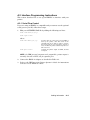
1
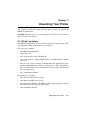
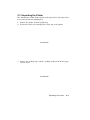
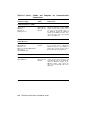
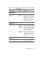
DEClaser 2200 Printer
Installation Guide
EK–D2200–IN–001
Digital Equipment Corporation
Maynard, Massachusetts
First Printing, June 1990
The information in this document is subject to change without notice and should not be
construed as a commitment by Digital Equipment Corporation.
Digital Equipment Corporation assumes no responsibility for any errors that may appear in
this document.
Any software described in this document is furnished under a license and may be used or
copied only in accordance with the terms of such license. No responsibility is assumed for
the use or reliability of software or equipment that is not supplied by Digital Equipment
Corporation or its affiliated companies.
Restricted Rights: Use, duplication, or disclosure by the U.S. Government is subject to
restrictions as set forth in subparagraph (c)(1)(ii) of the Rights in Technical Data and Computer
Software clause at DFARS 252.227–7013.
© Digital Equipment Corporation 1990
All rights reserved. Printed in Japan.
The Reader’s Comments form at the end of this document requests your critical evaluation to
assist in preparing future documentation.
The following are trademarks of Digital Equipment Corporation: BASIC Service, DECconnect,
DECdirect, DEClaser, DECmailer, DECmate, DECserver, DECservice, DECstation, EDT,
LN03, MicroVAX, PRO, Rainbow, VAX, VAX DOCUMENT, VAXmate, VAXstation, VAX/VMS,
VMS, WPS-PLUS, VT, and the DIGITAL Logo.
The following are third-party trademarks: BITSTREAM is a registered trademark of
Bitstream, Inc. Centronics is a trademark of Centronics Data Computer Corporation.
CG Times is a trademark of Compugraphic Corporation. CG Triumvirate is a trademark
of Compugraphic Corporation. IBM is a registered trademark of International Business
Machines Corporation.
IBM-PC is a trademark of International Business Machines
Corporation. ITC Souvenir is a registered trademark of International Typeface Corporation.
PostScript is a registered trademark of Adobe Systems, Inc.
S1387
This document was prepared using VAX DOCUMENT, Version 1.2.
FCC NOTICE: This equipment generates and uses radio frequency energy
and if not installed and used properly, that is, in strict accordance with the
manufacturer’s instructions, may cause interference to radio and television
reception. It has been type tested and found to comply with the limits
for a Class B computing device in accordance with the specifications in
Subpart J of Part 15 of FCC Rules, which are designed to provide reasonable
protection against such interference in a residential installation. However,
there is no guarantee that interference will not occur in a particular
installation. If this equipment does cause interference to radio or television
reception, which can be determined by turning the equipment off and on,
the user is encouraged to try to correct the interference by one or more of
the following methods.
–
Reorient the receiving antenna.
–
Relocate the computer or peripheral with respect to the receiver.
–
Move the computer or peripheral away from the receiver.
–
Plug the computer or peripheral into a different outlet so that they are
on different branch circuits than the receiver.
If necessary, the user should consult the dealer or an experienced radio/
television technician for additional suggestions. The user may find the
booklet How to Identify and Resolve Radio/TV Interference Problems,
prepared by the Federal Communications Commission helpful. This booklet
is available from the U.S. Government Printing Office, Washington DC,
20402, Stock No. 004-000-00345-4.
To meet FCC requirements, a shielded parallel cable is required to connect
the device to a personal computer or other Class B device.
3
Contents
v
Preface
Chapter 1 Preparing Your Site
1.1
1.2
1.3
Power Requirements . . . . . . . . . . . . . . . . . . . . . . . . . . . . . . .
Operating Location Requirements . . . . . . . . . . . . . . . . . . . . .
Environmental Conditions . . . . . . . . . . . . . . . . . . . . . . . . . . .
1–1
1–2
1–3
Chapter 2 Unpacking Your Printer
2.1
2.2
2.3
Printer Inventory . . . . . . . . . . . . . . . . . . . . . . . . . . . . . . . . . .
DEClaser 2200 Printer . . . . . . . . . . . . . . . . . . . . . . . . . . . . . .
Unpacking the Printer . . . . . . . . . . . . . . . . . . . . . . . . . . . . . .
2–1
2–2
2–3
Chapter 3 Cleaning the Fixing Assembly Roller
Chapter 4 Installing the EP-S Cartridge
Chapter 5 Loading Paper
Chapter 6 Connecting the Printer
6.1
Connecting to the Host Device . .
6.1.1
Serial Interface Connection . .
6.1.2
Parallel Interface Connection .
6.2
Connecting to a Power Source . .
.
.
.
.
.
.
.
.
.
.
.
.
.
.
.
.
.
.
.
.
.
.
.
.
.
.
.
.
.
.
.
.
.
.
.
.
.
.
.
.
.
.
.
.
.
.
.
.
.
.
.
.
.
.
.
.
.
.
.
.
.
.
.
.
.
.
.
.
.
.
.
.
.
.
.
.
.
.
.
.
.
.
.
.
.
.
.
.
6–1
6–2
6–4
6–5
iii
Chapter 7 Verifying the Installation
7.1
Checking the Printer Mechanism .
7.1.1
Testing the Printer . . . . . . . . . .
7.1.2
Producing a Test Print . . . . . . .
7.2
Conclusion . . . . . . . . . . . . . . . . . .
.
.
.
.
.
.
.
.
.
.
.
.
.
.
.
.
.
.
.
.
.
.
.
.
.
.
.
.
.
.
.
.
.
.
.
.
.
.
.
.
.
.
.
.
.
.
.
.
.
.
.
.
.
.
.
.
.
.
.
.
.
.
.
.
.
.
.
.
.
.
.
.
.
.
.
.
.
.
.
.
.
.
.
.
7–1
7–3
7–5
7–6
A.1 Cable Combinations . . . . . . . . . . . . .
A.2 Interface Programming Instructions
A.2.1
Serial Flow Control . . . . . . . . . . .
A.2.2
Parallel Communication . . . . . . . .
.
.
.
.
.
.
.
.
.
.
.
.
.
.
.
.
.
.
.
.
.
.
.
.
.
.
.
.
.
.
.
.
.
.
.
.
.
.
.
.
.
.
.
.
.
.
.
.
.
.
.
.
.
.
.
.
.
.
.
.
.
.
.
.
.
.
.
.
.
.
.
.
.
.
.
.
A–1
A–5
A–5
A–6
Cables and Adapters for Communication Connections . . . . . .
A–1
Appendix A Cabling Information
Tables
A–1
iv
Preface
The DEClaser 2200 printer is a nonimpact, desktop, page printer that can
print on both sides of a sheet of paper. This guide covers the installation
of the DEClaser 2200 printer up to the point where it is certified to be
operating properly.
Intended Audience
This guide is written for installers of the DEClaser 2200 printer.
Document Structure
This guide has seven chapters and one appendix.
Chapter 1, Preparing Your Site, discusses site preparation items, such as
power requirements, operating location, and environmental conditions.
Chapter 2, Unpacking Your Printer, describes how to unpack the printer
and identifies its parts.
Chapter 3, Cleaning the Fixing Assembly Roller, shows how to do an initial
cleaning of the fixing assembly roller.
Chapter 4, Installing the EP-S Cartridge, describes how to install the
electrophotographic supplies (EP-S) cartridge.
Chapter 5, Loading Paper, explains how to load paper.
Chapter 6, Connecting the Printer, shows how to connect the printer to
your computer system or video terminal.
Chapter 7, Verifying the Installation, explains how to run the self-test.
Appendix A, Cabling Information, explains how to cable your printer to
different systems, such as workstations and PCs.
NOTE: It is recommended to perform all procedures in the order given.
Ordering Additional Copies of This Documentation Set
You can order additional copies of this documentation set from DECdirect
as described in the ordering information section following Appendix D of
v
the DEClaser 2200 Printer Operator’s Guide. The ordering number for the
documentation is EK–D2200–DK.
The documentation set consists of:
•
One DEClaser 2200 Printer Installation Guide
•
One DEClaser 2200 Printer Operator’s Guide
•
One spine insert for the binder
•
One 3-ring binder
NOTE: You cannot order the installation or operator’s guide individually.
You can order only the documentation set.
Associated Documents
DEClaser 2200 Printer Operator’s Guide (EK–D2200–OP)
Digital ANSI-Compliant Printing Protocol Level 3 Programming Reference
Manual (AA–PBWGA–TE)
Digital ANSI-Compliant Printing Protocol Level 3 Programming Supplement (AA–PBWHA–TE)
Terms and Conventions
The following terms and conventions are used in this guide:
Term/Convention
Meaning
NOTE
Provides general information about the current topic.
CAUTION
Provides information to prevent damage to equipment.
WARNING
Provides information for preventing personal injury.
On Line
a key name is shown enclosed to indicate that you press that key on
the operator panel. For example:
1.
vi
Press
On Line
to place the printer on line.
Term/Convention
Meaning
Dash (—)
A statement beginning with a dash (—) describes the result of a
step. For example:
1.
Press
—
Check Mark ( )
On Line
to place the printer on line.
The On Line indicator lights.
A statement marked by a check mark ( ) indicates a special
instruction. For example:
1.
Remove the fixing assembly roller cleaner from the EP-S
cartridge box.
Identify the felt pad on one end of the fixing assembly
roller cleaner.
Laser Safety
The DEClaser 2200 printer complies with laser product performance
standards set by government agencies as a Class 1 Laser Product. The
DEClaser 2200 printer does not emit hazardous light, since the beam is
totally enclosed during all modes of customer operation and maintenance.
Ozone Safety
The DEClaser 2200 printer uses an ozone filter to remove the ozone
generated by the printer. The ozone filter should be replaced at the 100,000
page count. Refer to the DEClaser 2200 Printer Operator’s Guide for
instructions on replacing the ozone filter.
WARNING: Do not operate the printer without the ozone filter installed. The
filter removes ozone, which could be hazardous to your health.
vii
Chapter 1
Preparing Your Site
The performance of the DEClaser 2200 printer can be affected by electrical
and environmental conditions surrounding its work location. This chapter
lists the requirements for installing the DEClaser printer in a location
where it performs best.
1.1 Power Requirements
The wall outlet you use should meet the following requirements:
Area
Voltage
Frequency
Amperage
North America
120 Volts
50–60 Hz
8 Amp circuit
All others
220–240 Volts
50 Hz
5 Amp circuit
NOTE: Do not plug any other equipment into the same power supply line.
Preparing Your Site
1–1
1.2 Operating Location Requirements
The DEClaser 2200 printer should be installed in an area that meets the
following requirements:
•
A flat, level surface free from vibrations.
•
Enough surrounding space to allow ventilation and easy access to all
sides of the printer for servicing.
The following figure illustrates the space requirements for the printer:
mlo-004522
1–2 DEClaser 2200 Printer Installation Guide
1.3 Environmental Conditions
For the proper operation of the printer, be certain the following
environmental requirements are met:
•
Maintain the site within a temperature range of 10°C to 32.5°C (50°F
to 91°F).
•
Maintain a humidity range of 20% to 80% (noncondensing).
ensures consistent image quality and prevents paper jams.
•
Install the printer in a well-ventilated area to avoid heat buildup in the
unit.
•
Avoid installing the printer in a dusty area to protect moving parts from
unnecessary wear.
•
To prevent excessive ozone levels, avoid running many printers in the
same area without adequate ventilation.
•
To prevent condensation, avoid installing the printer in an area where
it is:
This
— Subjected to sudden changes in temperature or high humidity.
— Exposed to a draft of hot or cold air from a heating system or an
air conditioner or exposed to direct sunlight.
Preparing Your Site
1–3
Chapter 2
Unpacking Your Printer
This chapter describes the parts and the steps necessary to unpack the
DEClaser 2200 printer.
CAUTION: Damage will occur if the packing and spacers are not removed
before turning on the printer.
2.1 Printer Inventory
Your DEClaser 2200 printer and accessories come packed in two boxes. The
following lists identify what items are in each box.
The larger box contains:
•
One DEClaser 2200 printer
•
One power cord
•
One serial interface cable (BC16E–10)
•
One serial interface adapter (H8571–E) for coupling RS232 to RS423
connectors
•
Two 8½"-x-11" paper cassettes for North American applications or two
210-mm-x-297-mm paper cassettes for European or other applications
•
One screwdriverlike tool for removing the two large metal screws under
the rear output tray
•
One documentation binder
The smaller box contains:
•
One EP-S cartridge (in silver bag)
•
One fixing assembly roller cleaner
•
One cotton swab (Refer to the DEClaser 2200 Printer Operator’s Guide
for instructions on when to use the swab.)
•
One installation manual
Unpacking Your Printer
2–1
NOTE: Save the shipping carton and the packing material. They are useful
for transporting the printer.
2.2 DEClaser 2200 Printer
The following illustration shows the front and rear views of the printer with
the principal areas indicated.
mlo-004382
2–2 DEClaser 2200 Printer Installation Guide
2.3 Unpacking the Printer
The instructions in this chapter begin at the point where the printer has
been removed from the shipping box.
1. Remove the printer from the plastic bag.
2. Read, then remove the warning label on the top of the printer.
mlo-004383
3. Remove the packing tape and the packing cardboard from the paper
cassette slots.
mlo-004384
Unpacking Your Printer
2–3
4. Remove the packing tape from the rear of the printer.
mlo-004385
5. Use the screwdriverlike tool provided to remove the two long metal
screws on the back of the printer.
mlo-004386
2–4 DEClaser 2200 Printer Installation Guide
6. Remove the packing foam from inside the paper check area found on
the left side of the printer.
NOTE: The door is spring-loaded so you must hold it open as you remove
the packing material.
mlo-004512
7. Raise the green-handled lever in the paper check area.
mlo-004514
Unpacking Your Printer
2–5
8. Remove the warning label and attached foam sheet from the paper
check area.
Lower the green-handled lever.
mlo-004513
9. Press the release button on the top of the printer and raise the printer
cover to its most upright position.
mlo-004515
2–6 DEClaser 2200 Printer Installation Guide
10. Remove the packing foam inside the printer.
mlo-004516
11. Remove the two fixing assembly spacers.
mlo-004352
Unpacking Your Printer
2–7
12. Remove the top cover packing spacer.
mlo-004517
13. Remove the side packing spacer on the top cover.
mlo-004518
2–8 DEClaser 2200 Printer Installation Guide
Chapter 3
Cleaning the Fixing Assembly Roller
This chapter describes how to perform an initial cleaning of the fixing
assembly roller. This initial cleaning removes any shipping dust and
contaminants that may have settled on the roller.
You replace the fixing assembly roller cleaner each time you replace the
EP-S cartridge. A cleaner comes with each EP-S cartridge kit. Refer to the
DEClaser 2200 Printer Operator’s Guide for instructions on how to replace
the EP-S cartridge and the fixing assembly roller cleaner.
1. Remove the fixing assembly roller cleaner from the EP-S cartridge box.
Remove the fixing assembly roller cleaner from its packaging.
Identify the felt pad on one end of the fixing assembly roller cleaner.
The felt pad contains lubricating oil that stays on the roller as you
clean it.
mlo-004353
Cleaning the Fixing Assembly Roller
3–1
2. Open the green fixing assembly cover.
mlo-004354
3. Wipe the fixing roller with the felt pad on the end of the cleaner.
mlo-004355
3–2 DEClaser 2200 Printer Installation Guide
4. Peel off the felt pad and discard it.
mlo-004356
5. Insert the cleaner into the fixing assembly.
mlo-004357
Cleaning the Fixing Assembly Roller
3–3
6. Close the fixing assembly cover.
NOTE: The fixing assembly cover does not close tightly.
mlo-004358
3–4 DEClaser 2200 Printer Installation Guide
Chapter 4
Installing the EP-S Cartridge
This chapter describes how to install the electrophotographic supplies (EPS) cartridge.
It is important to handle the EP-S cartridge properly. Be aware of these
cautions when handling the EP-S cartridge.
CAUTIONS: Do not slide the cartridge cover open.
Do not stand the cartridge on end or place it upside down.
Do not shake the cartridge vigorously.
mlo-004359
Installing the EP-S Cartridge
4–1
1. Lower the top cover to its halfway position.
mlo-004519
2. Remove the EP-S cartridge from its protective bag.
mlo-004361
4–2 DEClaser 2200 Printer Installation Guide
3. Rock the EP-S cartridge five or six times as shown to distribute the
toner evenly.
mlo-004362
4. Install the EP-S cartridge.
mlo-004363
Installing the EP-S Cartridge
4–3
5. Snap the tab off the left side of the EP-S cartridge by moving it up and
down.
mlo-004364
6. Grasp the tab and pull the sealing tape completely out of the cartridge.
Discard the sealing tape.
NOTE: The sealing tape is about 55 cm (22") long and may have toner
on it. If you get toner on your hands or clothing, wash with cold water
and soap.
mlo-004365
4–4 DEClaser 2200 Printer Installation Guide
7. Close the top cover by pushing down on the hand grip until the cover
snaps into place.
mlo-004366
Installing the EP-S Cartridge
4–5
Chapter 5
Loading Paper
The DEClaser 2200 printer has two paper cassette slots and comes with
two paper cassettes. This chapter describes how to unpack a paper cassette
and how to load paper into the DEClaser 2200 printer. Each paper cassette
holds about 200 sheets of 80 g/m2 (21 lb) paper. For further information
about the kind of paper to use, refer to the DEClaser 2200 Printer Operator’s
Guide.
The following instructions demonstrate how to unpack a paper cassette and
how to load paper into the paper tray.
1. Remove the paper cassette from its shipping bag.
NOTE: The paper cassette consists of a cover and a tray.
2. Separate the cassette cover from the tray and remove all packing
material from the tray.
mlo-004367
Loading Paper
5–1
3. Insert paper into the left side of the tray being sure it is inserted below
the paper guide and the maximum height guard.
To prevent paper jams, do not place an excessive amount of paper
into the tray. There should be a small amount of space between the
paper and the maximum height guard.
Make sure the paper lies perfectly flat in the tray.
mlo-004368
5–2 DEClaser 2200 Printer Installation Guide
4. Replace the cassette cover on the paper tray.
mlo-004369
5. Insert the paper cassette into the printer.
NOTE: It is not necessary to load paper into both paper cassettes and
to place both cassettes into the printer at this time.
mlo-004520
Loading Paper
5–3
Chapter 6
Connecting the Printer
This chapter describes how to connect your printer to the host device and
to a power source.
6.1 Connecting to the Host Device
Your printer is equipped with both a serial interface connector and a parallel
interface connector.
See your system manager or computer operator to determine what interface
connection to use.
NOTE: Refer to Appendix A for detailed information on connecting your
DEClaser printer to different host devices.
mlo-004521
Connecting the Printer
6–1
6.1.1 Serial Interface Connection
Follow these directions for the serial interface connection:
1. Plug one end of the BC16E cable into the host device.
2. Attach the H8571–E adapter, which came with your printer, to the
serial port on the back of the printer.
Use a flathead screwdriver or your fingers to secure the adapter to
the printer.
mlo-004372
6–2 DEClaser 2200 Printer Installation Guide
3. Plug the remaining end of the BC16E cable into the H8571–E adapter.
mlo-004373
NOTE: Refer to Appendix A for information on host devices that do not
accept the BC16E cable.
Connecting the Printer
6–3
6.1.2 Parallel Interface Connection
The parallel interface cable (BC19M–10) is not included with your printer.
To purchase it, call DECdirect at 1–800–DIGITAL.
Follow these directions for the parallel interface connection:
CAUTION: Before connecting the parallel interface cable, be sure the host
device you are connecting to is turned off.
1. Plug the end of the BC19M–10 cable with the two screws attached to
it firmly into the host device.
2. Tighten the two screws.
3. Plug the other end of the BC19M–10 cable into the printer.
4. Secure the cable to the printer by pressing the clips over the sides of
the connector.
mlo-004374
6–4 DEClaser 2200 Printer Installation Guide
6.2 Connecting to a Power Source
CAUTION: Be sure to check that the wall outlet voltage matches the voltage
of your printer. Your electrician can make this determination for you if you
do not know.
The power cord receptacle and power switch are located at the rear of the
printer.
1. Make sure the printer is in the OFF (O) position.
mlo-004375
Connecting the Printer
6–5
2. Plug the power cord into the power cord receptacle just below the power
switch.
mlo-004376
3. Insert the other end of the power cord into a power outlet.
WARNING: Do not use an adapter plug on the power cord.
6–6 DEClaser 2200 Printer Installation Guide
Chapter 7
Verifying the Installation
This chapter describes how to check the printer mechanism and how to
print a test page.
7.1 Checking the Printer Mechanism
This section describes how to determine if the printer is running properly.
1. Press the power switch to the ON ( | ) position.
mlo-004377
Verifying the Installation
7–1
— The Ready indicator on the operator panel flashes, the Alarm and the
Data indicators light, and 02 WARMING UP appears on the liquid
crystal display (LCD).
mlo-004378
When the printer warms up (about one minute), 00 READY DEC appears
on the display, and the On Line and Ready indicators light.
You are now ready to print.
7–2 DEClaser 2200 Printer Installation Guide
7.1.1 Testing the Printer
This section describes how to perform a printer self-test. The test page
looks like the sample on the following page and only verifies that the printer
mechanism is functioning properly.
1. Using a ballpoint pen or like instrument, press the self-test button
located on the right side of the printer.
mlo-004379
Verifying the Installation
7–3
— 15 ENGINE TEST appears on the LCD display, and a test image of
vertical stripes prints.
mlo-004380
7–4 DEClaser 2200 Printer Installation Guide
7.1.2 Producing a Test Print
The following test shows that the printer, with the exception of the interface
unit, is working properly.
1. Press
On Line
2. Press
Test/Font
to place the printer in the offline state.
for 2 seconds.
— 05 TEST PRINT A appears on the display, and the following test
image prints.
mlo-004381
Verifying the Installation
7–5
7.2 Conclusion
This concludes the installation of your DEClaser 2200 printer. Refer to
your DEClaser 2200 Printer Operator’s Guide for detailed instructions on
features, maintenance, and troubleshooting.
7–6 DEClaser 2200 Printer Installation Guide
Appendix A
Cabling Information
This appendix describes the different cable combinations to use for
connecting your printer to a host device. It also explains serial flow control
and parallel communication.
A.1 Cable Combinations
In the first column of Table A–1, the devices you can connect your printer
to are grouped by the type of connector required. The second column lists
the part numbers of the adapter and the cable required for each device.
Determine what device you have and obtain the appropriate adapter. The
third column describes how to connect the adapter and/or the cable to the
printer.
NOTE: For a complete list of accessories and supplies and instructions on
how to order them, refer to the DEClaser 2200 Printer Operator’s Guide.
Table A–1: Cables and Adapters for Communication Connections
Connector Type
Adapter and
Cable
Instruction
25-Pin Plug Devices
VAXstation 3200/3500
VT100 Series
DECserver 200/MC (DSRVB–AA)
CPU RS232 Ports
1 H8571–E
H8571–A and
H8571–E1 and
BC16E1
Attach the H8571–A (25-pin-to-MMJ)
adapter to these devices, then connect
one end of the BC16E cable to
the H8571–A. Attach the H8571–E
adapter to the DEClaser printer, then
connect the other end of the BC16E
cable to the H8571–E.
and BC16E (DECconnect cable) are included with the DEClaser 2200 printer.
Cabling Information
A–1
Table A–1 (Cont.): Cables and Adapters for Communication
Connections
Connector Type
Adapter and
Cable
Instruction
9-Pin Plug Devices (DEC)
VT200 Series
DECmate
PRO Series
VAXstation 2000
H8571–B and
H8571–E1 and
BC16E1
Attach the H8571–B (9-pin-to-MMJ)
adapter to these devices, then connect
one end of the BC16E cable to
the H8571–B. Attach the H8571–E
adapter to the DEClaser printer, then
connect the other end of the BC16E
cable to the H8571–E.
H8571–E1 and
BC16E1
Attach one end of the BC16E cable
to one of these devices. Attach the
H8571–E adapter to the DEClaser
printer, then connect the other end of
the BC16E cable to the H8571–E.
H8571–D and
H8571–E1 and
BC16E1
Attach the H8571–D adapter to one
of these devices, then connect one end
of the BC16E cable to the H8571–D.
Attach the H8571–E adapter to the
DEClaser printer, then connect the
other end of the BC16E cable to the
H8571–E.
DEC423 (MMJ)
Serial Devices
VAXmate
MicroVAX 2000
DECserver 300
DECserver 200/DL (DSRVB–BA)
VT300 Series
CPU DEC423 Ports
25-Pin Socket Devices
Rainbow
Digital Modems
1 H8571–E
and BC16E (DECconnect cable) are included with the DEClaser 2200 printer.
A–2 DEClaser 2200 Printer Installation Guide
Table A–1 (Cont.): Cables and Adapters for Communication
Connections
Connector Type
Adapter and
Cable
Instruction
9-Pin Plug Devices
(IBM PC/AT Type)
DECstation 210, 212
DECstation 316, 320
IBM PC/AT
H8571–J and
H8571–E1 and
BC16E1
Attach the H8571–J adapter to one of
these devices, then connect one end
of the BC16E cable to the H8571–J.
Attach the H8571–E adapter to the
DEClaser printer, then connect the
other end of the BC16E cable to the
H8571–E.
Use data transmit ready (DTR) flow
control. Refer to the DEClaser 2200
Printer Operator’s Guide.
200 Series
12–27591–01
Extender and
H8571–A and
H8571–E1 and
BC16E1
Connect the female end of the extender
cable to the host device and the
male end of the extender cable to
the H8571–A. Attach the H8571–E
adapter to the DEClaser printer, then
connect one end of the BC16E to the
H8571–A and the other end of the
BC16E cable to the H8571–E.
300, 350 Series
H8571–A and
H8571–E1 and
BC16E1
Attach the H8571–A adapter to one of
these devices, then connect one end
of the BC16E cable to the H8571–A.
Attach the H8571–E adapter to the
DEClaser printer, then connect the
other end of the BC16E cable to the
H8571–E.
BC19M–10
Connect the BC19M–10 to the DEClaser
printer and to the host device.
European DECstations
Serial Port
European DECstations
Parallel Port
200, 300, 350 Series
1 H8571–E
and BC16E (DECconnect cable) are included with the DEClaser 2200 printer.
Cabling Information
A–3
Table A–1 (Cont.): Cables and Adapters for Communication
Connections
Connector Type
Adapter and
Cable
Instruction
Existing Cable
BC22D cable (already installed)
1 H8571–E
H8571–C and
H8571–E1 and
BC16E1
Connect the H8571–C adapter plug to
the socket of your printer’s BC22D
cable. Connect one end of the BC16E
cable to the H8571–C adapter. Attach
the H8571–E adapter to the DEClaser
printer, then connect the other end of
the BC16E cable to the H8571–E. The
combination of the H8571–C adapter,
the BC16E cable, and the H8571–E
acts as a straight-through cable.
and BC16E (DECconnect cable) are included with the DEClaser 2200 printer.
A–4 DEClaser 2200 Printer Installation Guide
A.2 Interface Programming Instructions
This section describes how to set up an IBM PC to interface with your
printer.
A.2.1 Serial Flow Control
If you are using an IBM PC or compatible and you want to use the optional
serial port on your PC, follow these steps:
1. Edit your AUTOEXEC.BAT file by adding the following two lines:
mode com1:4800,n,8,1,p
mode lpt1:=com1:
where:
mode com1:4800,n,8,1,p
specifies that the first serial port (COM1) is
used by the printer, that 4800 baud is the
communication speed, that no parity is selected,
that 8 data bits are selected, that 1 stop bit is
used, and that the printer continuously retries on
time-out errors.
mode lpt1:=com1:
reassigns the printer output to COM1, the first
serial port.
NOTE: On IBM personal computers and compatibles, printer output is
normally directed to LPT1, the first parallel port.
2. Connect the H8571–A adapter as described in Table A–1.
3. Refer to the DEClaser 2200 Printer Operator’s Guide for instructions
on how to select DTR flow control.
Cabling Information
A–5
If you are using a 25-pin PC/SA with XON/XOFF, follow these steps:
1. Edit your AUTOEXEC.BAT file to contain the following two lines:
mode com1:4800,n,8,1,-,n
mode lpt1:=com1:
where:
mode com1:4800,n,8,1,-,n
specifies that the first serial port (COM1) is
used by the printer, that 4800 baud is the
communication speed, that no parity is selected,
that 8 data bits are selected, that 1 stop bit is
used, that the printer tries only once to connect,
then time-out, and that the type weight is normal.
mode lpt1:=com1:
reassigns the printer output to COM1, the first
serial port.
NOTE: On IBM personal computers and compatibles, printer output is
normally directed to LPT1, the first parallel port.
2. Connect the H8571–A adapter as described in Table A–1.
3. Refer to the DEClaser 2200 Printer Operator’s Guide for instructions
on how to select XON/XOFF.
A.2.2 Parallel Communication
If you are using an IBM PC, DECstation PC, or compatible and want to
use the parallel port, follow these steps:
1. Refer to the DEClaser 2200 Printer Operator’s Guide for instructions
on how to select parallel operation.
2. Use Digital’s BC19M–10 cable or the industry standard Centronics 25pin D-shell cable to make the connection from the PC to the DEClaser
2200 printer.
A–6 DEClaser 2200 Printer Installation Guide