1
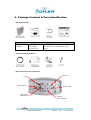
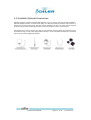
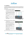
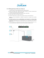
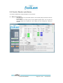
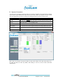
Pisces Digital
ICS Repeater
Product Manual
Edition
Edition 1.2, D e cem ber 2 2, 201 2.
Copyrights
The information contained herein is the property of Coiler Corporation. No part
of this document may be reproduced or transmitted in any form or by any
means, electronic or mechanical and for any purpose without the prior written
permission of Coiler.
Copyrights © 2012. All rights reserved.
Pisces Product Manual
Page 2
of 24
1. About This Manual
This product manual is produced for the use of Coiler’s Pisces (PS) Digital ICS
Repeater by Coiler personnel, licensees and customers.
The Pisces Digital ICS Repeater has the most innovative technologies to simplify the
installation process. Please first refer to the single sheet installation guide. This
manual covers the functions of the Pisces (PS) in detail with OMT instructions
(Section 8) and is needed only when the information on the single sheet installation is
insufficient.
Due to the continued progress in methodology, design and manufacturing of our
products, the contents of this document are subject to revision without any notice.
Coiler assumes no legal responsibility for any error or damage resulting from the use
of this document.
Your comments can assist us in improving our products and services. Please address
them to Coiler at any time.
Address :
th
8F-4, No. 75, Sec. 1, Xintai 5 Rd, Xizhi Dist. New Taipei City 221,
Taiwan (R.O.C.)
Phone :
+886 2 2698 2618
Fax :
+886 2 2698 2629
Web site :
www.coiler.com.tw
Email :
[email protected]
Pisces Product Manual
Page 3
of 24
2. Table of Contents
1. About this Manual ....................................................................................3
2. Table of Contents .....................................................................................4
3. Safety Instructions ..................................................................................5
4. Package Contents & Parts Identification .........................................6
5. Product Introduction ...............................................................................7
5.1. Product Features ....................................................................................8
A. Isolation Cancellation System .......................................................8
B. Automatic Gain Adjustment ..........................................................8
C. Automatic Gain Control ................................................................8
D. Auto Shut Down & Auto Turn On ..................................................8
5.2. LED Indications ......................................................................................9
5.3. Available Optional Accessories ............................................................ 10
6. Installation ............................................................................................... 11
6.1. Standard Package Installation .............................................................. 11
6.2. Utilizing External Donor Antenna .......................................................... 11
6.3. Utilizing External Service Antenna ....................................................... 12
7. Testing ...................................................................................................... 13
8. Accessing the PS with Coiler OMT ................................................... 14
8.1. .NET Framework 3.5 Installation .......................................................... 14
8.2. OMT Installation ................................................................................... 16
8.3. Micro USB Driver Installation ............................................................... 18
8.4. OMT Login ........................................................................................... 19
8.5. Control, Monitor and Alarms.................................................................. 19
A. Admin Screen Shot..................................................................... 19
B. Operator Screen Shot................................................................. 22
C. User Screen Shot ....................................................................... 23
9. Troubleshooting ...................................................................................... 24
Pisces Product Manual
Page 4
of 24
3. Safety Instructions
Any personnel involved in an installation, operation or service of the Coiler PS Digital ICS
Repeater must understand and obey the following:
1.
Coiler PS Digital ICS Repeaters must be used exclusively for its application described in
this guide’s product introduction and nothing else.
2.
For your safety, please be aware of power lines at all times during installation and use.
Please make sure to take appropriate safety measures for protection. Contact with
high-voltage power lines can cause serious injury or death.
3.
Please handle the equipment with care. Mechanical shock due to the dropping or
mishandling of the repeater can permanently damage sensitive RF components.
4.
The PS Digital ICS Repeater is designed for indoor applications and should be kept
away from water and humidity.
5.
The primary AC power range for the repeater is AC100-240V. It is possible to damage the
repeater if the primary AC power is outside this range.
6.
Conducted emissions can only be carried out when the DC cable is less than 3m long. Please
operate the repeater with DC power cable included in the package and not cables longer than
3m.
7.
An external lightning protector is recommended when the antenna is installed outdoors.
8.
The operating temperature of this product should be between 0°C ~ 40°C.
9.
Any repeater, including Coiler’s PS Digital ICS Repeater, will generate radio signals and
thereby give rise to electromagnetic fields that may be hazardous to the health of any
person who is extensively exposed to the signals, and is in the immediate proximity of a
repeater or repeater antennas. Therefore, the minimum distance between the user and/or
any bystander and the radiating structure (antenna) of the transmitter is 50cm.
*Coiler’s PS Digital ICS Repeater complies with or exceeds EMC safety and RF
requirements, as per 1995/5/EC Directive.
Pisces Product Manual
Page 5
of 24
4. Package Contents & Parts Identification
Standard Package:
Accessories Information
Model Name
AC Adaptor
EA10521B-060
Power Rating
I/P: 100-240V~1.8A, 50-60Hz; O/P: 6V 6A
DC Power Cord
120cm
Optional Package Additions:
Base Connections & Components:
OMT Port
Power
Built-in Service
Built-in Donor
MS Coupler
-10dB from MS
Pisces Product Manual
Optional
Support Bracket
Page 6
of 24
5. Product Introduction
Pisces, or PS-2200 is Coiler’s Pico level ICS
(Isolation Cancellation System) repeater. ICS is a
breakthrough technology that cancels isolation up
to 25dB and enables the Pisces to be equipped
with built in donor and service antenna. With
intuitive LED indicators, an average mobile phone
user can simply plug in the power and place the
PS-2200 at the best signal window location for
optimal performance.
In addition to ICS technology, the PS also has
Auto Gain Adjustment (AGA) up to 25dB should
the environment requires attenuation of gain - no
action is required by the user. Standard safety
features such as Auto Gain Control (AGC), Auto
Shutdown (ASD), and Auto Turn-on (ATO) are all
packaged into the PS to ensure network and
product safety.
When signal is weak by the window or when PS
would not be place beside a window, external
donor antenna could be used to ensure the
receptiono of quality signal. When multiple areas
requires service, the PS also has ability to connect
external service antenna(s). Whenever external
antennas are used, wall mount brackets is an
option for better placement and unit stability.
The PS is not only flexible in unit deployment but
also with service frequencies. Coiler’s OMT
software provides the ability for the configuration of
3G service channels to ensure the PS would be
amplifying the signal of a particular operator.
Simple, complete, and versitile, the PS-2200 digital
ICS repeater is an unique offering for carriers to
solve the 3G coverage problems of their clients
instantly.
Pisces Product Manual
Page 7
of 24
5.1 Product Features
The PS Digital ICS Repeater represents some of the most innovative technologies from Coiler. The key
technology that defines the PS is the Isolation Cancellation System (ICS). In addition, the Pisces also
feature technologies such as Automatic Gain Adjustment (AGA), Automatic Gain Control (AGC), Auto
Shut Down (ASD) and Auto Turn On (ATO). Each feature is described in details below.
A. Isolation Cancellation System
Isolation Cancellation System (ICS) is a complex technology. However, the over function can be simply
to the following definition:
All RF signal has three parameters: amplitude (A), phase (Ø), and time delay (T). ICS repeater has a
digital engine that differentiates the real input and feedback signal, then controls and reduces the
amplitude, phase and time delay of feedback signal. Hence echo is cancelled and antennas can be
much closer than repeaters without ICS technology. The formulas below illustrate a 25dB isolation
improvement comparing repeaters without ICS technology and Pisces Digital ICS Repeater.
Repeater without ICS technology: Isolation ≥ Gain + 15dB
Pisces Digital ICS Repeater: Isolation ≥ Gain – 10dB
B. Automatic Gain Adjustment
Working hand in hand with the ICS technology within the Pisces is the Automatic Gain Adjustment
(AGA) with 25dB range. This is a dynamic function that adjusts the gain of the Pisces whenever
isolation becomes insufficient. The full gain of Pisces repeater is 70dB when isolation is 60dB or higher.
When a situation causes the isolation to be lower than 60dB, AGA would reduce the gain immediately
to avoid oscillation. For example, if an object is placed directly in front Pisces repeater on the service
side, this would cause the service signal to feedback to donor and reduce the isolation value. In this
case if isolation becomes 50dB, then AGA would reduce the gain of the repeater by 10dB to avoid
oscillation. Maximum attenuation of AGA is 25dB, which means the Pisces repeater would adjust
automatically for best performance as long as isolation is high than 35dB.
C. Automatic Gain Control
Automatic Gain Control (AGC) is also a dynamic gain adjustment feature with 25dB of range. AGC
adjust the gain of Pisces whenever the input power is higher than -60dBm. Since the maximum gain of
Pisces is 70dB and the maximum output power +10dBm on the DL, whenever input RSSI is higher
than -60dBm, AGC would make the appropriate attenuation to keep the output power consistent at the
max output power level of +10dBm. Maximum attenuation of AGC is 25dB, which means Pisces
repeater can adjust to any circumstance with RSSI of -35dBm or lower. Pisces would shut down when
input power is -35dBm or higher. The use of repeater should not be required when signal level is that
strong.
D. Auto Shut Down and Auto Turn On
When the input power exceeds AGC range on the DL or UL by 3dB, Pisces would activate its
advanced set safety mechanism: Auto Shut Down (ASD) and Auto Turn On (ATO). ASD is a stage that
temporarily stops the RF function of PS. On the UL it will continuously detect the input power and
resume RF function as soon as the input power reduces to a safe range. For the DL, it will make three
attempts to detect the input power in this temporary stage. If the input power reduces to a safe range
for the PS to operate, the ATO feature would power the repeater back on and restore all functions
promptly. However, if the input power remains too great and dangerous for the network, it will then shut
down completely. In such the signal is too strong for the usage of Pisces repeater.
Note: shutdown level of Pisces is at +13dBm (3dB higher than maximum output power), which
translates to an input power of -32dBm after full AGC attenuation).
Pisces Product Manual
Page 8
of 24
5.2 LED Indications
The Pisces Digital ICS Repeater is designed with built-in LED indicators to simplify the installation process.
Details indications can be found below. In general, the more green LEDs the better when it comes to the two
sets of LEDs for RSSI and Isolation.
Label
Status
On
POWER
Blinking
Indication
Calls are being made through the repeater.
3 seconds after no calls are being made, repeater would go into
sleep mode.
Overpower; Over temperature; Isolation; Unit faulty.
ALARM
RSSI
On
Alarm could be caused by any one of the conditions above.
Please check with OMT for exact cause of alarm.
Off
Normal.
0 on
<-95dBm – basically no signal detected. External donor
recommended.
1 on
-94~-89dBm – signal is weak. Although repeater can work,
service area may be limited due to weak input signal.
2 on
-88~-83dBm – signal is sufficient. Service area still limited.
3 on
-82~-77dBm – recommended minimum input is -80dBm.
Therefore with 3 LED on, the repeater is functioning well.
4 on
-76~-71dBm – signal is good. Coverage area can be around
2
250m with this input signal.
5 on
>-70dBm – signal is strong. PS has can perform well under most
conditions with 5 LEDs on. However, to achieve maximum output
power of 10dBm, input should be at -60dBm. This value can be
checked with OMT. See section 7.5 for OMT monitor information.
Only need to check then Isolation LED when external donor or service antenna is in use.
ISOLATION
0 on
<39dB – donor and service are too close. Isolation alarm would
be triggered when isolation value reaches 35dB.
1 on
40~44dB
2 on
45~49dB
3 on
50~54dB
4 on
55~59dB
5 on
>60dB – isolation is good. PS can perform with maximum gain.
Isolation not ideal. Whenever isolation is below 60dB,
AGA would reduce according to isolation value to
avoid oscillation. For maximum gain, ensure that all 5
isolation LED are on.
* UL Stand-By Mode would be activated when UL signal is <-90dBm for over 3 seconds. 90dBm). UL Stand-By
Mode deactivates when UL signal is >-85dBm. When UL Stand-By Mode is activated, green power LED will
be blinking until UL transmission resumes.
Pisces Product Manual
Page 9
of 24
5.3 Available Optional Accessories
Standard package of the Pisces Digital ICS Repeater is for one service area plug and play installation.
Optional package includes one three meter cable, one 7dBi panel antenna (could be used as donor or
service) and a wall mount bracket. With the optional packages, the user can easily use the external
antenna to either locate a better signal location or use the antenna to service a second area.
Should there be a need to service more than two rooms/areas, optional cabling and antennas can be
purchased through a Coiler sales representative. Below is a list of available accessories to maximize
the use of your Pisces Digital ICS repeater.
Pisces Product Manual
Page 10
of 24
6. Installation
The installation of Pisces Digital ICS repeater without external antenna(s) is really just placing the unit
next to the window and plugging in the power. However due to natural or manmade obstacles and the
direction of the source signal, signal may not be sufficient for the Pisces to work properly. This section
provides instruction on how to identify the best placement location and the application of Pisces with
external antenna(s).
6.1 Standard Package Installation
Be sure to review the Quick Installation Guide
for instructions on removing the base cover.
Review Section 4 for connections at the base.
•
•
•
•
Locate a window location where you would like
to place the repeater main unit. The back of
repeater should be at least partially higher than
the bottom of the window to ensure receiving
of signal.
Power on the repeater connecting the main
unit with AC power supply unit and plugging
into a wall socket.
Check the RSSI LED. Coiler recommend
minimum of 3 RSSI LED for quality
performance.
When RSSI LED is less than 3, please locate a
different window or refer to the 6.2 for external
antenna utilization.
6.2 Utilizing External Donor Antenna
This section refers to using components from
the optional package.
•
•
•
•
•
Disconnect the built-in donor port (refer to
Section 4 for base connections) and connect
the 90° end of the 3 meter cable instead.
Connect the 7dBi panel antenna to the other
end of the 3 meter cable (should you need a
longer cable or different antenna, please
speak to a Coiler representative).
Search for a better signal location by
checking the RSSI LED. Be sure to have 3
RSSI LED or more.
When external antenna is used, be sure to
check the Isolation LED. Best to have all 5
Isolation LED lid.
Mount the external donor antenna once an
ideal location is found.
Note: when not all of the Isolation LED’s are lid, the gain of the repeater maybe less than 70dB.
Pisces Product Manual
Page 11
of 24
6.3 Utilizing External Service Antenna
This section refers to using components from the optional package.
•
•
•
•
Remove the dummy load on MS CPL port (refer to Section 4 for base connections) and
connect the 90° end of the 3 meter cable instead.
Connect the 7dBi panel antenna to the other end of the 3 meter cable.
Please make sure that all 5 Isolation LED are lid.
Determine best location to mount the donor antenna to service a second area/room.
Speak to a Coiler representative for additional components for multiple service antenna
application.
•
•
The built-in service port has a +10dB difference from the MS CPL port. When multiple
antennas would be used, it is recommended that the built-in antenna to be connected to MS
CPL port and external antennas to the original service port to compensate for the cable and
splitter loss.
Due to the difference of 10dB output, whenever built in service antenna would not be in use, it
is recommended that the original service port be used instead of the MS CPL port.
Pisces Product Manual
Page 12
of 24
7. Testing
Test the repeater’s performance by making phone calls using a mobile phone of the
appropriate operator in various locations in the installation site. Ensure that the signal is
available in the locations most distant from the service antennas and in the corners of the facility. In
case there are any problems with these tests, please refer to the Troubleshooting section (Section 9)
of this manual.
For RF testing of various parameters, please download and install OMT for PS-2200. The ICS
function generates interference signal to the testing equipment and would distort the testing result. The
PS OMT has different test mode for the testing of different parameters to ensure accurate readings,
please refer to section 10.5 under B – Operator Screenshot for test mode settings.
Note: With the ICS function on, the Pisces Digital ICS repeater meets all 3GPP and has been
certified by the responsible authorities.
Pisces Product Manual
Page 13
of 24
8. Accessing the PS with Coiler OMT
The Pisces Digital ICS repeater is designed to be a simply Plug & Connect DIY solution. The use of
OMT would be strictly for changing of service frequency or to switch the unit into different test modes.
To download the PS OMT, please visit Coiler’s FTP site below:
ftp://ftp.coiler.com.tw/_ftp_/coilerclient/OMT/PS2200/
You will find the OMT file itself as well as the driver for the mini USB cable under this folder.
This FTP site is password protected. Please contact your Coiler representative for login user
name and password.
8.1 .NET Framework 3.5 Installation
If you are using Windows XP, please install .NET Framework 3.5. It can be downloaded from Microsoft
website or from Coiler ftp site. The full download for the file is around 231MB. Please follow the
installation instruction once the file is downloaded and launched.
Windows 7 user does not need to install this software addition since it is already built in.
8.2 OMT Installation
The file downloaded from the FTP site is a zip file. You need to unzip the file before launching
the installation.
You must install both the OMT software and the USB Driver before accessing the PS via the
USB port.
Double click on the OMT SOHO Series installation file to start the installation.
A welcome screen will appear. Simply click “Next” to continue. You can specify where to install
the software in your hard drive as well as who would have access to the Coiler OMT.
Pisces Product Manual
Page 14
of 24
Once the OMT finishes the installation, you can locate it either in the “Start” menu under “All
Programs” in the “Coiler” folder or you can find it on your desktop labeled “OMT”.
You will NOT be able to access the PS with OMT at this point. Please continue to the next
section before attempting launching OMT.
Pisces Product Manual
Page 15
of 24
8.3 USB Driver Installation
Unzip and run the “PreInstaller” file of the USB driver.
Follow the on screen installation instruction to complete the driver installation.
At this stage, the three part software/driver installation is complete.
Before launching the OMT, you will need to find out which COM port the PS repeater uses. To find out which COM
port to use, you would need to connect the PS to your computer in order to find out the exact COM port
number.
Once the PS and the computer are connected. Right click on “My Computer” and select
“Properties”. Once inside properties, select the “Device Manager”.
Pisces Product Manual
Page 16
of 24
•
Next you would need to find “Ports (COM & LPT)” in the hardware hierarchy chart. Expand “Ports
(COM & LPT)” and locate “USB Serial Port” and note down the COM number (in the example
below it is COM3, your setting may be different). You are now ready to launch the Coiler OMT.
Pisces Product Manual
Page 17
of 24
8.4 OMT Login
Now that you have all the software installed and know the COM port number, double click on the OMT
software icon on your desktop or under coiler folder from the Start Menu. You will see the following
screen.
User Accounts
user
operator
Password
test
coiler
admin
Contact Coiler
Representative
Pisces Product Manual
Privilege
Only view status
Set different test mode
Set different test mode
Frequency adjustment
Log information for troubleshoot
Page 18
of 24
8.5 Control, Monitor and Alarms
This section indicates the working description of each function.
A. Admin Screenshot
-
The administrator can press “Ctrl + F12” to see the detail polling information and save
the information.
Press “Polling” if you with to get the most updated repeater status. You may also set
automatic polling by checking the “Auto Polling” box and indicate the interval in
seconds.
Pisces Product Manual
Page 19
of 24
Control Descriptions:
DL Start
Adjustable by 0.1MHz. Use the up and down arrow to adjust or simply type
the frequency you wish in.
DL Stop
Always 15MHz difference from the DL Start Frequency.
UL Start
Will automatically be calculated base on DL Start Freq.
UL Stop
Will automatically be calculated base on DL Stop Freq.
CH 1
Digital On/Off switch of the first 5MHz of your 15MHz selection.
CH 2
Digital On/Off switch of the middle 5MHz of your 15MHz selection.
CH 3
Digital On/Off switch of the last 5MHz of your 15MHz selection.
Look UP
Opens separate window for frequency selection by region and operator.
Double click to change frequency to intended operator’s frequency.
Set Freq
Test Mode
AGC Trailing
Applies the adjusted frequency to the repeater.
Select the mode to test for particular parameter.
Default off. When AGC trailing is on,
Pisces Product Manual
Page 20
of 24
Monitor Descriptions:
Input Power
Indicating the input power of both DL and UL detected by the repeater.
Gain
Indicating the DL and UL gain of repeater. UL gain will display as N/A during
UL standby mode (blue sleep button).
Output Power
Displays the DL and UL output power of the repeater. UL output power will
display as Low during UL standby mode (blue sleep button).
CH1
Displays the DL and UL working status of first 5MHz of your 15MHz
selection. DL will show sleep when channel is switched off or when no signal
of this channel is detected.
CH2
Displays the DL and UL working status of middle 5MHz of your 15MHz
selection. DL will show sleep when channel is switched off or when no signal
of this channel is detected.
CH3
Displays the DL and UL working status of last 5MHz of your 15MHz
selection. DL will show sleep when channel is switched off or when no signal
of this channel is detected.
Isolation
Displays the isolation value detected by repeater.
AGA ATT
Adjustment made by AGA when isolation is insufficient.
Temperature
Operating temperature of the repeater.
Alarm Descriptions:
DL Over Power
This can happen when DL input power reaches -32dBm or higher.
UL Over Power
This can happen when too many people are using the repeat
simultaneously.
Isolation
Triggers when isolation value is <35dB.
Over Temperature
Triggers when temperature is over 75°C. Repeater will recover at 65°C.
PLL-Unlock
Triggered when repeater hardware fails. If alarm persist, contact Coiler for
warranty information.
Pisces Product Manual
Page 21
of 24
B. Operator Screenshot
The ICS function generates interference signal to the testing equipment and would distort the testing
result. Hence a list of different test modes can be found under “admin” and “operator” account. Please
select the appropriate test mode according to the testing parameters to ensure accurate result.
Test Mode
Purpose
ICS ON
Default setting. Always select this option to ensure proper functioning of PS.
ICS UL
Select this option to test UL standby mode.
DL ICS OFF
UL PA would be off and DL signal would become analog with this test mode.
UL ICS OFF
DL PA would be off and UL signal would become analog with this test mode.
OUT BAND GAIN
Select this test mode to test out of band gain.
NOISE FIGURE
Select this test mode to test noise figure.
Both “admin” and “operator” also has the ability to switch AGC Trailing on/off. When AGC trailing is on,
UL AGC will follow DL AGC. By default, AGC trailing is off so UL and DL AGC would work
independently.
Pisces Product Manual
Page 22
of 24
C. User Screenshot
User mode does not have ability to modify any setting. Only viewing of status is available.
Pisces Product Manual
Page 23
of 24
9. Troubleshooting
Please first refer to troubleshooting section of the Quick Installation Guide.
Situation
Solution
There is still no signal after the
•
installation of the equipment.
Ensure that the output power of the Adaptor is DC 6V /
6A and that green power LED is illuminated.
•
Ensure that all connections are tightly fastened.
•
Ensure that the outdoor signal level (RSSI) is sufficient.
(Coiler recommends a signal strength greater than 80dBm, or three green RSSI LED).
•
If external donor antenna is used, ensure that all
connections are tightly fastened.
The signal strength is too weak
•
Reconnect the power cable.
•
Ensure a strong donor signal level (RSSI) of -80dBm or
in the corner.
better is achieved (three green RSSI LED).
•
Adjust the placement location of the PS repeater or
consider using external donor antenna.
The repeater’s signal is not stable.
•
Use the coupler port to install additional service
•
Ensure that the outdoor signal is stable.
•
If external donor/service antenna is used, ensure that
the Isolation LED has five green LED.
The red Alarm LED is lit.
•
Consider changing location of PS repeater or connect
•
Ensure that input RSSI is not -32dBm or higher.
•
If alarm persist even though RSSI is less than -32dBm,
Log into OMT to review the alarms list for exact alarm
description.
•
Pisces Product Manual
For PLL-Unlock alarm, contact a Coiler representative.
Page 24
of 24