1
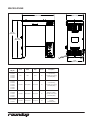
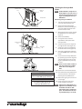
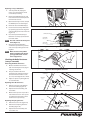
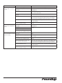
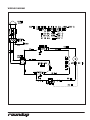
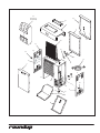
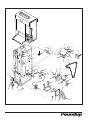
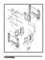
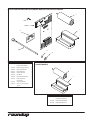
VCT-1000 Vertical Contact Toaster owner’s manual Manufacturing Numbers: 9210700, 9210702, 9210704, 9210705, 9210706, 9210708, 9210709, 9210710, 9210711, 9210712, 9210714, 9210716, 9210720, 9210722, 9210727 www.ajantunes.com P/N 1010807 Rev. K 07/14 CONTENTS GENERAL GENERAL2 Warranty Information2 Service/Technical Assistance2 Important Safety Information3 Warnings3 Specifications4 Installation5 Unpacking5 Assembling the Unit 5 Equipment Setup 6 Operating Instructions6 Safety Features 6 Hi-Limit Reset Button 6 Conveyor interlock Safety switch 6 Maintenance7 Daily7 Replacing the Black and Silver Release Sheet (Every 4–6 weeks) 7 Replacing the Optional Belt Wraps (Every 3–6 months) 7 Checking the Conveyor Belt Chains 8 Checking the Roller Tensioners (every 3–6 months) 9 TROUBLESHOOTING10 Wiring Diagram 12 Replacement Parts 13 Parts Identification 13 Mechanical Butter Wheel Kit (P/N 7000298) Requires Professional Installation.18 Mechanical Butter Wheel Kit (model 7000238) 18 Notes19 Limited Warranty 20 This manual provides the safety, installation, and operating procedures for your toaster. Please read all of the information contained in this manual prior to installing and operating the toaster. Your toaster is manufactured from the finest materials available and is assembled to Roundup’s strict quality standards. This toaster was tested at the factory to ensure dependable trouble-free operation. WARRANTY INFORMATION Please read the full text of the Limited Warranty in this manual. If the unit arrives damaged, contact the carrier immediately and file a damage claim with them. Save all packing materials when filing a claim. Freight damage claims are the responsibility of the purchaser and are not covered under warranty. The warranty does not extend to: yy Damages caused in shipment or damage as result of improper use. yy Installation of electrical service. yy Normal maintenance as outlined in this manual. yy Malfunction resulting from improper maintenance. yy Damage caused by abuse or careless handling. yy Damage from moisture into electrical components. Damage from tampering with, removal of, or changing any preset control or safety device. IMPORTANT SERVICE/TECHNICAL ASSISTANCE If you experience any problems with the installation or operation of your system, contact A.J. Antunes & Co. at 1-630-7841000, or toll free in the United States at 1-800-253-2991. Fill in the information in the next column and have it handy when calling for assistance. The serial number is on the specification plate located on the system. Purchased From Date of Purchase Model Number Serial Number Mfg. Number Use only genuine Roundup replacement parts in this unit. Use of replacement parts other than those supplied by the manufacturer will void the warranty. Your Authorized Service Agency has been factory trained and has a complete supply of parts for this unit. Visit www. ajantunes.com or contact the factory at 1-630-784-1000 to locate your nearest Authorized Service Agency. Refer to the service agency directory packaged with your manual and fill in the information below. Authorized Service Agency A.J. Antunes & Co. reserves the right to change specifications and product design without notice. Such revisions do not entitle the buyer to corresponding changes, improvements, additions or replacements for previously purchased equipment. Name Phone Number IMPORTANT Address Keep these instructions for future reference. If the unit changes ownership, be sure this manual accompanies the equipment. 2 P/N 1010807 Rev.K 07/14 IMPORTANT SAFETY INFORMATION Use the following guidelines for safe operation of the unit. yy Read all instructions before using equipment. yy For your safety, the equipment is furnished with a properly grounded cord connector. Do not attempt to defeat the grounded connector. yy Install or locate the equipment only for its intended use as described in this manual. Do not use corrosive chemicals in this equipment. yy Do not operate this equipment if it has a damaged cord or plug, if it is not working properly, or if it has been damaged or dropped. yy This equipment should be serviced by qualified personnel only. Contact your nearest Authorized Service Agency for adjustment or repair. yy Do not block or cover any openings on the unit. yy Do not immerse cord or plug in water. yy Keep cord away from heated surfaces. yy Do not allow cord to hang over edge of table or counter. yy Turn the power off, unplug the power cord, and allow unit to cool down before performing any service or maintenance on the unit. yy The procedures in this manual may include the use of chemical products. See Hazard Communication Standard manual for the appropriated Material Safety Data Sheets (MSDS). yy The equipment should be grounded according to local electrical codes to prevent the possibility of electrical shock. It requires a grounded receptacle with separate electrical lines, protected by fuses or circuit breaker of the proper rating. yy All electrical connections must be in accordance with local electrical codes and any other applicable codes. yy Do not clean this appliance with a water jet. P/N 1010807 Rev. K 07/14 WARNINGS Be advised of the following warnings when operating and performing maintenance on this unit. yy If the supply cord is damaged, it must be replaced by the manufacturer or its service agent or a similarly qualified person in order to avoid a hazard. yy Do not modify the power supply cord plug. If it does not fit the outlet, have a proper outlet installed by a qualified electrician. yy Do not use an extension cord with this appliance. yy Electrical ground is required on this appliance. yy Check with a qualified electrician if you are unsure if the appliance is properly grounded. yy If a chemical cleaner is used, be sure it is safe to use on cast aluminum. Observe all precautions and warnings on product label. yy Inspection, testing, and repair of electrical equipment should only be performed by qualified service personnel. yy This equipment is to be installed to comply with the basic plumbing code of the Building Officials and Code Administrators, Inc. (BOCA) and the Food Service Sanitation Manual of the Food and Drug Administration (FDA). yy To ensure proper steaming characteristics, some calcium/mineral deposits must be present on the generator surface. If, during cleaning, the surface does become free of calcium/ mineral deposits, add plain tap water to the surface and allow it to boil off. This may have to be repeated several times to ensure proper steaming characteristics by creating a thin layer of deposits on the surface. yy Do not use a sanitizing solution or abrasive materials. The use of these may cause damage to the stainless steel finish. yy Chlorides or phosphates in cleaning agents (e.g. bleach, sanitizers, degreasers or detergents) could cause permanent damage to stainless steel equipment. The damage is usually in the form of discoloration, dulling of metal surface finish, pits, voids, holes, or cracks. This damage is permanent and not covered by warranty. 3 The following tips are recommended for maintenance of your stainless steel equipment: yy Always use soft, damp cloth for cleaning, rinse with clear water and wipe dry. When required, always rub in direction of metal polish lines. yy Routine cleaning should be done daily with soap, ammonia detergent, and water. yy Stains and spots should be sponged using a vinegar solution. yy Finger marks and smears should be rubbed off using soap and water. yy Hard water spots should be removed using a vinegar solution. SPECIFICATIONS 10-3/4” (237.1 mm) 20-5/16” (516.0 mm) 23-7/32” (590.0 mm) 22-11/16” (576.2 mm) 9-3/4” (248.0 mm) Model & Mfg. No. Volts Watts Amp. Hertz Description VCT-1000CF 9210700 9210706 9210716 9210722 120 1800 15.0 60 5-15P, 15 Amp., 120 VAC, Non-locking (Assembly Only) VCT-1000CV 9210702 9210708 9210709 9210714 9210720 9210727 208/240 2600/3455 12.5/14.4 60 6-20P, 20 Amp., 250 VAC, Non-locking (Assembly Only) VCT-1000HI 9210704 9210705 9210710 9210711 208/240 2600/3455 12.5/14.4 50 IEC-309, 16 Amp., 250 VAC, Pin & Sleeve (Assembly Only) VCT-1000HC 9210712 220/240 1775/2125 8.07/8.85 50 CEE 7/7, 16 Amp., 250 VAC (Assembly Only) 4 P/N 1010807 Rev.K 07/14 INSTALLATION Unpacking BUN FEEDER HEAT SHIELD 1. Remove unit and all packing materials from shipping carton. RELEASE SHEET 2. Open the large box. It should contain: • • • • Bun Feeder (Figure 1) Bun Chute (Figure 2) Two Release Sheets (Figure 1) Authorized Service Agency Directory • Owner’s Manual 3. Remove all packing materials and protective coverings from the unit and parts. NOTE: If any parts are missing or damaged, contact Antunes Technical Service IMMEDIATELY at 1-877392-7854. REAR CONVEYOR BELT CHAIN PLATEN YELLOW SUPPORT ROD (REAR) YELLOW SUPPORT ROD (FRONT) CONVEYOR INTERLOCK SWITCH FRONT CONVEYOR BELT CHAIN CONVEYOR COVER ASSY. (REAR) CONVEYOR COVER ASSY. (REAR) SHOWN WITHOUT OPTIONAL ROLLER TENSIONERS AND BELT WRAPS. Assembling the Unit NOTE: The factory has pre-installed a Release Sheet over the Platen (Figure 1). Verify that it is properly in place before proceeding. CAUTION Failure to use Release Sheets may result in damage to the unit and loss of warranty coverage. Figure 1. Toaster and Accessories BUN FEEDER HOOK BUN CHUTE OVER REAR BOTTOM CONVEYOR COVER YELLOW SUPPORT ROD HEAT SHIELD 1. Install the Bun Feeder (Figure 1) and Bun Chute (Figure 2). NOTE: Make sure Heat Shield Assembly is properly seated and engages the Conveyor Interlock Safety Switch (see Figure 1). The conveyors will not rotate unless the Heat Shield is in place and correctly engages the Conveyor Interlock Safety Switch. NOTE: Check the Release Sheet to make sure it is not caught in the conveyor. Additional Release Sheets can be purchased through your Authorized Service Agency under P/N 7000249 (3-pack) or 7000250 (10-pack). CONVEYOR COVER ASSY. (REAR) YELLOW SUPPORT ROD CONVEYOR COVER ASSY. (FRONT) SHOWN WITHOUT OPTIONAL ROLLER TENSIONERS AND BELT WRAPS. BUN CHUTE Figure 2. Installing Bun Chute P/N 1010807 Rev. K 07/14 5 Equipment Setup When placing the toaster into service, pay attention to the following guidelines. yy Make sure power to the unit is off and the toaster is at room temperature. yy Do NOT block or cover any openings on the unit. yy Do NOT immerse cord or plug in water. yy Keep cord away from heated surfaces. yy Do NOT allow cord to hang over edge of table or counter. yy Connect the unit to the power supply. Refer to the specification plate for the proper voltage. WARNING OPERATING INSTRUCTIONS 4. Drop buns into toaster. Cut sides of heel and crown must face each other. 6. Test at least 4 buns before putting toaster into service. Turn temperature control to lower setting for lighter toasting or to higher setting for darker toasting. NOTE: After initial run of 4-6 buns, adjust controls according to the desired finished product. 2. Turn the power on (Figure 6). 7. Turn the power off when finished toasting and follow the daily cleaning procedures. 3. Turn the temperature control to 10 and allow the unit to warm up for 30 minutes. BUN THICKNESS ADJUSTMENT CONTROLS (SEE FIGURE 7) ELECTRICAL SHOCK HAZARD. Failure to follow the instructions in this manual could result in serious injury or death. THICKNESS 3 THICKNESS HI-LIMIT RESET 6 5 2 1 4 • Electrical ground is required on this appliance. 5. Toasted product will drop into the bun landing area (Figure 6). 1. Set the Bun Thickness Compression Knobs (Figure 7) to the desired settings. 1 5 6 1 = 1/2"(12.7mm) 2 = 5/8"(15.9mm) 3 =11/16"(17.5mm) 4 = 3/4"(19.1mm) 5 =13/16"(20.6mm) 6 = 7/8"(22.2mm) 4 2 3 • Do NOT modify the power supply cord plug. If it does not fit the outlet, have a proper outlet installed by a qualified electrician. • Do NOT use an extension cord with this appliance. • The toaster should be grounded according to local electrical codes to prevent the possibility of electrical shock. It requires a grounded receptacle with separate electrical lines, protected by fuses or circuit breaker of the proper rating. RESET BUTTON BUN LANDING AREA 3 THICKNESS THICKNESS 6 5 2 CAUTION 1 4 1 5 CAUTION Bread may burn. Therefore toasters must not be used near or below curtains or other combustible walls and materials. Failure to maintain safe operating distances may cause discoloration or combustion. TEMPERATURE CONTROL Figure 6. Toaster Controls • Check with a qualified electrician if you are unsure if the appliance is properly grounded. All electrical connections must be in accordance with local electrical codes and any other applicable codes. POWER SWITCH PROTECTIVE CAP 6 1 2 3 4 5 6 = 1/2"(12.7mm) = 5/8"(15.9mm) =11/16"(17.5mm) = 3/4"(19.1mm) =13/16"(20.6mm) = 7/8"(22.2mm) 4 2 3 Figure 7. Bun Thickness Compression Knobs SAFETY FEATURES Hi-Limit Reset Button A Hi-Limit Control turns off electrical power to the heater if the unit overheats. To reset this control, allow 10-15 minutes for the unit to cool down, Remove the Protective Cap, and fully press the Reset Button located at the rear of the unit (Figure 6). 6 If the unit requires continuous resetting, contact your Authorized Service Agency. Conveyor interlock Safety switch A Conveyor Interlock Safety Switch is located on top of the unit under the Heat Shield (Figure 1). The Conveyor Belt Chains will not rotate unless the Heat Shield is in place and activating the Conveyor Interlock Safety Switch properly. P/N 1010807 Rev.K 07/14 MAINTENANCE Daily CAUTION Turn the power off, disconnect the power cord, and allow the unit to cool down 30 minutes before performing any service or maintenance. CAUTION To prevent damage to the unit, do not use abrasive cleaners on the Release Sheet or belt wrap. CAUTION Failure to use Release Sheets may result in damage to the unit and loss of warranty coverage. Tools Required: yy yy yy yy Heat-Resistant Gloves Clean Towels Multipurpose Detergent Solution Sanitizer Solution 1. Turn the power off, unplug the power cord, and allow the unit to cool for 30 minutes. 8. Close the front Conveyor Cover, open the rear Conveyor Cover, and clean the Belt Wrap (if used) or Conveyor Belt Chain as described in Step 7. 9. Close the rear Conveyor Cover and reinstall the Heat Shield. Then plug in the power cord, turn the unit on, count 10 seconds, then turn the unit off and unplug the unit. This will allow the uncleaned sections to be exposed. 10. Open the rear Conveyor Cover again, clean the newly exposed section of the Belt Wrap (if used) or the Conveyor Belt Chain in the same manner as before. Close the Conveyor Cover. 11. Open the front Conveyor Cover again and clean the newly exposed section of the Belt Wrap (if used) or Conveyor Belt Chain in the same manner as before. 12. Close the front Conveyor Cover and wipe down the outside of the toaster with a clean, damp, sanitized towel. 13. Install a new or clean Release Sheet, using the reverse side, by draping it over both sides of the Platen with the crease centered on the Platen. 2. Put on heat resistant gloves. Remove the Bun Feeder, Heat Shield, and Bun Chute (Figure 1). NOTE: Rotate from side to side daily or weekly to prolong the life of the Release Sheet. 3. Wipe the Bun Feeder, Heat Shield, and Bun Chute with a damp sanitized towel and allow them to air dry. 14. Install the Bun Chute so the hooks are installed over the lower rear yellow Support Rod. 4. Remove the Release Sheet and place it on a clean, flat dry surface. 15. Install the Heat Shield with the Release Sheet retainer clips securely over the Release Sheet and Platen. 5. Wipe the silver side with a clean towel dampened with Multipurpose Detergent Solution immediately followed by a second clean towel dampened with sanitizer. Allow it to air dry before continuing. 6. Once the silver side of the Release Sheet is dry, repeat Step 5 on the black side. If properly cleaned, the Release Sheet surface should be smooth to the touch when dry. 7. Open the front Conveyor Cover and firmly wipe the Belt Wrap (if used) or Conveyor Belt Chain from left to right and top to bottom with a clean towel dampened with Multipurpose Detergent Solution immediately followed by a second clean towel dampened with sanitizer solution. P/N 1010807 Rev. K 07/14 16. Reinstall the Bun Feeder and plug in the unit. NOTE: Make sure the Heat Shield is activating the Conveyor Safety Interlock Switch. The conveyors will not rotate unless the Heat Shield is in place and the switch is activated. NOTE: Additional Release Sheets can be purchased through your Authorized Service Agency under P/N 7000249 (3-Pack) or 7000250 (10-Pack). Replacing the Black and Silver Release Sheet (Every 4–6 weeks) NOTE: Depending on toaster usage and on how well it is cleaned daily, the Release Sheet should last between 45–60 days. 1. Remove and discard the Release Sheet. 2. Lay a new Release Sheet on a clean, dry surface and fold it in half lengthwise and gently crease it at the fold using only your fingers (Figure 8). 3. Install the Release Sheet just as you would after Daily Cleaning. FOLD OVER SO ENDS MEET. PRESS LIGHTLY WITH FINGER TO FORM CREASE. Figure 8. Folding the Release Sheet Replacing the Optional Belt Wraps (Every 3–6 months) NOTE: Depending on toaster usage and how well they are cleaned daily, the Belt Wraps should last between 3–6 months. Additional Belt Wraps may be purchased from your Authorized Service Agency. 1. Turn unit off, unplug the power cord, and allow the unit to cool before proceeding. 2. Remove the Bun Feeder and Heat Shield and set the Bun Thickness Compression Knobs to 6 & 6. 3. Open both Conveyor Covers and pull the Belt Wrap Pin out of the zipper (Figure 9). 4. Remove and discard the old Belt Wrap(s). 5. Clean both Conveyor Belt Chains just as you would clean the Belt Wraps during daily cleaning. 6. Install the new Belt Wrap(s) around the Conveyor Belt Chains inside the yellow rods with the zipper flap exposed and hanging down (Figures 10 & 11). 7. Close the Conveyor Cover(s), set the Bun Thickness Compression Knobs back to their normal settings and reinstall the Heat Shield and Bun Feeder. 7 CONVEYOR BELT CHAINS CONVEYOR COVER ASSY. INTERLOCK SWITCH BELT WRAP PIN Checking the Conveyor Belt Chains NOTE: The Bun Thickness Compression Knobs (Figure 7) must be set to “6 & 6” prior to measuring or removing or reinstalling the Conveyor Belt Chains. Measuring conveyor belt Chains 1. Turn the unit off, unplug the power cord, and allow the unit to cool. 2. Remove the Bun Feeder, Butter Wheel, Pan, and Heat Shield (Figure 1) and set the Bun Thickness Compression Knobs to 6 & 6. Figure 9. Removing Optional Belt Wrap 3. Open both Conveyor Covers and pull the Belt Wrap Pin out of the zipper (Figure 9). UPPER SUPPORT ROD 4. Remove the Belt Wrap. 5. Facing the toaster, locate the approximate center-point of the Conveyor Chain. LOWER SUPPORT ROD BELT WRAP PIN 6. Pull the Conveyor Chain away from the edge of the toaster (Figure 12). 7. Stand a U.S. Dime on end between the frame and the chain (Figure 12). 8. If the gap is significantly wider than the coin, REMOVE links as described below. Figure 10. Installing Belt Wrap 9. Disconnect the Conveyor Belt Chain by squeezing any two links together and unhooking both ends one link (Figure 13). Needle-nose pliers may be used. INCORRECT NOTE: There are two small 1/2” links on each side of the Conveyor Belt Chain. The rest are large 3/4” links. CORRECT Figure 11. Aligning Belt Teeth 10. Remove one 1/2” link from the belt. CAUTION Align the ends of the Belt Wrap properly (Figure 11) or the Belt Wrap may be damaged. CAUTION Position the Belt Wrap inside the upper and lower yellow support rods or damage to the unit may occur. 8 11. Reassemble the Conveyor Belt Chain onto the sprockets as described in Replacing Conveyor Belt Chains. 12. Measure the gap again to ensure it is not too tight. 13. Check the opposite side of the toaster using the same steps. NOTE: If the Conveyor Belt Chain is too tight to be reassembled, remove an additional small 1/2” link and install a large 3/4” link in its place. This will shorten the Conveyor Belt Chain by 1/4” overall. P/N 1010807 Rev.K 07/14 Replacing conveyor belt Chains 1. Turn the power off, unplug the power cord, and allow the unit to cool before proceeding. 2. Remove the Butter Wheel, Pan, and Heat Shield and set the Compression Control Knobs to 6 & 6. 3. Open both Conveyor Covers and pull the Belt Wrap Pin out of the zipper. 4. Remove & discard old Belt Wrap(s). Figure 12. Removing Conveyor Belt Chain 5. Disconnect the Conveyor Belt Chain by squeezing any two links together and unhooking both ends of one link (Figure 13). 6. Place the replacement Conveyor Belt Chain on the top sprockets with hook ends down. NOTE: The ends of the hooks must point down (Figure 13). 7. Wrap the Conveyor Belt Chain around the top and lower sprockets and connect by hooking both ends together. ROTATION UPPER SUPPORT ROD LARGE LINK P/N 0800121 SMALL LINK P/N 0800204 Figure 13. Removing Conveyor Belt Chain NOTE: Make sure the Conveyor Belt Chain is installed under the Upper Support Rod and over the Lower Support Rod. Checking the Roller Tensioners (every 3–6 months) Measuring The Roller Tensioners 1. Measure the Roller Tensioner on both inner Conveyor Covers (Figure 14) using a U.S Nickel. 2. The space between the inner Conveyor Cover and bottom of the Tensioner wheel should be 13/16” (2.1 cm) or the height of a U.S. Nickel. 3. Adjust or replace any damaged ones as recommended. Figure 14. Measuring Roller Tensioner ACORN NUTS WELD SCREWS TENSIONER ASSY. Replacing the roller tensioners 1. Remove acorn nuts and old Roller Tensioner Assembly (Figure 15). SPACERS TAPE 2. Replace Tensioner Assembly, and reassemble. Figure 15. Replacing Roller Tensioner Assy. 3. Make sure the spacers are placed inside the Tensioner arm. The spacers are smaller than the holes to allow the Tensioner to pivot freely. Replacing the spring tensioner ACORN NUTS WELD SCREWS TAPE 1. Remove the acorn nuts (Figure 16). 2. Remove the old Spring Tensioner Assembly (Figure 16). SPRING TENSIONER ASSY. 3. Replace Tensioner Assembly and reassemble unit. P/N 1010807 Rev. K 07/14 Figure 16. Replacing Spring Tensioner Assy. 9 TROUBLESHOOTING WARNING To avoid possible personal injury and/or damage to the unit, inspection, test and repair of electrical equipment should be performed by qualified service personnel. The unit should be unplugged when servicing, except when electrical tests are required. Use extreme care during electrical circuit tests. Live circuits will be exposed. Problem No heat and Conveyor Belt Chains do not move. Possible Cause Corrective Action Toaster is installed incorrectly. Perform the installation and operating procedures found in the Installation and Operation sections of this manual. Inoperable Power Cord or Power Switch. Check receptacle for correct voltage (see the Specifications section of this manual). If necessary, contact your maintenance person or Authorized Service Agency for service. No heat but Conveyor Belt Chains move. Hi-Limit Control is tripped. Reset the Hi-Limit Control (see Figure 6 in the Operations section of this manual). Wiring problem. Contact your maintenance person or Authorized Service Agency for service. Wiring problem. Contact your maintenance person or Authorized Service Agency for service. Inoperative Platen. Inoperable Thermostat Platen is hot but Conveyor Belt Chains do not rotate. Heat Shield not installed. Install Heat Shield (Figure 2). Conveyor Safety Interlock Switch not activated by the Heat Shield. Re-install the Heat Shield correctly so that the Heat Shield applies appropriate pressure on the Conveyor Safety Interlock Switch. Spring Tensioner Assembly or Roller Tensioner is damaged or missing. Replace Spring Tensioner or Roller Tensioners if damaged or missing. Conveyor Belt Chain links too loose. Adjust Conveyor Belt Chain length as described in the Maintenance section of this manual. Inoperable Drive Motor. Contact your maintenance person or Authorized Service Agency. Loose Drive Motor Sprocket Setscrew. Drive Motor Chain has fallen off sprocket(s). Inoperable Safety Interlock Switch. Conveyor Belts Chains hesitate to rotate and/or skip on sprockets. Conveyor Belt Chains installed incorrectly. Install Conveyor Belt Chains to match Figure 11. Be sure that the ends of the hooks are facing down. Conveyor Belt Chains too loose. Adjust Conveyor Belt Chain length as described in the Maintenance section of this manual. Spring Tensioner Assembly or Roller Tensioner is damaged or missing. Replace Spring Tensioner Assembly or Roller Tensioners if damaged or missing. 10 P/N 1010807 Rev.K 07/14 Problem Product is over toasted, Platen heat is too high, or drop time is too slow. Product is under toasted, Platen heat is too low, or drop time is too fast. Possible Cause Corrective Action Temperature set too high. Set temperature control to a lower setting. Bun Thickness Compression Knobs set improperly. Measure bun thickness and set Bun Thickness Compression Knobs correctly (Figure 7). Buns sticking on Release Sheet. Clean or replace Release Sheet according to the procedure in the Maintenance section of this manual. Conveyor Cover Assembly not installed properly. Re-install Conveyor Cover Assembly. Loose sprocket setscrews. Check drive chain for kinks, broken or bent links, or other damage. Check motor sprocket and drive sprockets; tighten setscrew on flat of shaft if required. Check for damaged/worn sprocket and replace as required. Conveyor Belt Chain too loose. Adjust Conveyor Belt Chain length as described in the Maintenance section of this manual. Spring Tensioner Assembly or Roller Tensioner is damaged or missing. Replace Spring Tensioner Assembly or Roller Tensioner if damaged or missing. Bun Thickness Compression Knobs set improperly. Measure bun thickness and set Bun Thickness Compression Knobs correctly (Figure 7). Wiring problem. Contact your maintenance person or Authorized Service Agency for service. Inoperable Thermostat. Conveyor Drive Motor inoperable or incorrect conveyor motor installed in toaster. Product is getting stuck or Conveyor Belt Chains stop when product is toasting. P/N 1010807 Rev. K 07/14 Bun Thickness Compression Knobs Set improperly. Measure bun thickness and set Bun Thickness Compression Knobs correctly. Release Sheet not cleaned properly or is missing. Clean or replace Release Sheet as described in the Maintenance section of this manual.. Conveyor Drive motor inoperative or incorrect conveyor motor installed in toaster. Contact your maintenance person or Authorized Service Agency for service. Conveyor Drive Chain loose, worn, or broken. Loose motor drive sprocket. Check drive chain for kinks, broken or bent links, or other damage. Check motor sprocket and drive sprockets, tighten setscrew on flat of shaft if required. Check for damaged/worn sprockets and replace as required. Conveyor Belt Chain too loose. Adjust Conveyor Belt Chain length as described in the Maintenance section of this manual. Spring Tensioner Assembly or Roller Tensioner is damaged or missing. Replace Spring Tensioner Assembly or Roller Tensioner if damaged or missing. 11 WIRING DIAGRAM NOTE: ALL WIRES TO BE 14 GA. AWM-105°C UNLESS OTHERWISE SPECIFIED. * 16 GA. TFE-200°C = 18 GA. AWM-105°C # 16 GA. AWM-105°C % 14 GA. TFE-200°C GRN GRN-YEL TERMINAL BLOCK GND HI-LIMIT THERMOSTAT WHT WHT *WHT %WHT 1 2 4 5 PLATEN HEATER POWER SWITCH BLK BLK GRN = WHT INDICATOR LIGHT THERMOSTAT =BLK WHT/BLU BLK/BRN POWER CORD M MOTOR 50 Hz % BLK 60 Hz % BLK INTERLOCK SWITCH 12 % BLK 50 Hz P/N 1010807 Rev.K 07/14 REPLACEMENT PARTS Parts Identification INTERLOCK SWITCH DRIVE CHAIN IDLER SPROCKET FRONT DRIVE SPROCKET REAR DRIVE SPROCKET TEMPERATURE CONTROL THERMOSTAT FAN BLADE POWER SWITCH HI-LIMIT CONTROL DRIVE MOTOR ASSY. P/N 1010807 Rev. K 07/14 13 92 (optional–use only with #93) 93 91 64 3 94 38 35 76 66 34 ION UT CA 52 10 33 95 3 77 44 33 39 83 45 8 82 81 48 86 93 14 P/N 1010807 Rev.K 07/14 36 67 16 72 70 42 70 53 12 54 70 62 57 17 67 18 17 19 32 75 70 67 80 25 50 17 20 57 61 42 36 74 70 67 72 87 17 70 84 39 24 83 11 23 67 P/N 1010807 Rev. K 07/14 23 19 21 12 28 43 15 46 58 22 2 16 1 37 70 5 4 67 34 9 41 79 78 7 6 7 88 51 4 31 1 27 85 76 40 2 67 30 9 41 26 67 89 76 90 65 6 7 85 16 83 P/N 1010807 Rev.K 07/14 ItemPart No. Description 1 0011266 0800204 0800121 2 2150117 3 0011609 4 0010475 5 0800332 6 7000207 7 7000199* 8 0011444 9 2150118 10 0700452 0700463 0700437 0700453 11 4030355 12 7000296 16 7000167 16A 7000224 17 2150181 2150109 18 2150187 2150215 19 0011299 20 0011300 21 0503589 22 7000240 7000282 7000271 0012112 0011390 23 2150199 2150211 2150112 2150173 2150193 24 4010245 Qty. 25 4060355 Conveyor Belt (Incl. Items 2 26 0503495 Below) 1/2” Pitch Link, Small 2 ItemPart No. 3/4” Pitch Link, Large 38 27 0503507 Idler Shaft 2 28 4060229 Conveyor Cover Assy. 2 4060323 (Incl. #95) 29 0011374 Tensioner Assy. 4 30 0503496 (Incl. #40, 76, 85) 31 0503497 Rod, Conveyor Cover 4 32 1000899 Sprocket (Incl. #65) 8 33 10P1047* Spacer Kit 2 34 2100253 Control Cover 1 35 0011445 Drive Shaft 2 36 2100133 Power Cord/Plug, 1 37 0021170 NEMA 6-20P 38 7000249 Power Cord/Plug, 1 7000250 NEMA 5-15P 39 0021194 Power Cord/Plug, 1 40 7000121 IEC-309 Power Cord/Plug, CEE 7/7 1 41 0021207 Thermostat, 600°F 1 42 7000176 Ball Bearing (Pack of 2) 1 43 4030332 Bearing & Retainer Kit 6 44 0400251 Bearing & Retainer Kit 1 0400315 (Incl. Six of #16) Drive Sprocket 2 Drive Sprocket (Mfg. No. 2 45 0400138 9210705 only) 46 0503590 Drive Chain 1 48 0503385 Drive Chain 1 50 331P101* (for Mfg. #9210714 & 720) 51 7000200 Idler Sprocket & Bearing 1 7000229 Bracket, Idler Sprocket 1 7000289 (Incl. #50, 57, 61, 19, & 87) 522100266 Bracket, Motor Mounting 1 53 4010107 Drive Motor Kit 230V 1 57 0503608 (Incl. #58) 58 4000170 Drive Motor Kit 120V 1 59 2100256 (Incl. #58) 61 212P118* Drive Motor Kit 230V 1 62 0500464 (for Mfg. #9210714 & 720) 64 0011528 Gearmotor Assy 230V 3 RPM 1 65 325P163 (for Mfg. #9210705) 66 100P864* Drive Motor Assy - 1 230V/9RMP 67 308P154* Sprocket, Motor (Mfg. 2 68 306P104* #9210700, 702, 69 406P107* 706, & 708) 70 308P143* Sprocket, Motor (Mfg. 2 71 310P103* #9210704, 710 72 310P140* & 9210712) 73 308P101* Sprocket, Motor 2 74 306P101* (for Mfg #9210714 & 720) 75 306P123* Sprocket, Motor 2 76 308P145* (Mfg. No. 9210716 & 722) 77 100P900* Sprocket, 25B24 1/2” Bore 1 (Front) (Mfg. No. 9210711) 78 325P104* P/N 1010807 Rev. K 07/14 Rocker Switch, On/Off 1 Terminal Block 1 Retainer, Tension Bracket, RH 2 Description Qty. Retainer, Tension Bracket, LH 2 Indicator Light, Amber (250V)1 Indicator Light, Amber (125V)1 Spring Tensioner Assy. 2 Tensioner Bracket, Right 2 Tensioner Bracket, Left 2 Label, Control 1 Label, Dial (Pack of 10) 1 Knob, Cam 2 Cover, End Housing 1 Knob, Thermostat Control 1 Weldment, End Housing 1 Release Sheet (Pack of 3) Release Sheet (Pack of 10) Weldment, Control Housing 1 Slide Rail Kit (Incl. Two 2 Slide Rails for Tensioners) Conveyor Cam 2 Thermocouple Retainer Kit 2 High Limit Control 1 Strain Relief 1 Strain Relief 1 (Mfg # 9210704 only) Locknut, 1/2” 1 Bracket, Motor 1 Bun Chute 1 Nut, Hex, 5/16 x 18” 1 Platen, 208V 1 Platen, 120V 1 Platen, 230V (Mfg. #9210712)1 Tape 2 Interlock Switch 1 Cover Plate 2 Fan Blade, Motor 1 Tape, Hi-Temp 8 Flat Washer, 5/16” 1 Retainer, Bearing 1 Heat Shield Assy. 1 Setscrew, 1/4-28 x 5/16” 8 Label, Caution Hot 1 Screw, #10-32 x 3/8” 2 Screw, #6-32 x 1/4” 8 Cable Tie 1 Nut, #8-32, “KEPS” 6 Screw, #10-32 x 1/4” 4 Washer, #10 6 Nut, #8-32 3 Nut, Hex, #6-32 2 Screw, #6-32 x 7/8” 2 Nut, Hex Acorn, #8-32 14 Label, Service 1 Washer, 1/4” 4 17 79 325P109* Screw, 1/4-20 x 1/2” 80 308P124* Screw, 1-Way, #8-32 x 1/2” 81 210P230 Bumper, Recess Leg, 1” ItemPart No. Description 4 1 4 Qty. 82 310P136* Screw, #10-32 x 1-1/4” 4 83 308P133* Screw, #8-32 x 1/4” 12 84 308P183* Screw, Hex Head, #8-32 x 3/8”4 85 308P181* Screw, Flat Hd., #8-32 x 3/8” 4 86 218P145* Cover, Leg, Bumper 4 87 331P103* Shoulder Bolt, 5/16”-18 1 88 306P105* Screw, #6-32 x 1/2” 1 89 0503455 Tension Spring, Inner 4 90 2100259 Slide Bar 4 91 0011549 Bun Feeder 1 92 7000192 Belt Wrap (optional for 1 Mfg. No. 9210716 722 & 727) 93 0011491 Conveyor Cover Assy. 1 (Mfg. No. 9210706, 708, 710, 716, 722, & 727) (Incl. #94) 94 7000186 Roller Tensioner Kit 1 (Pack of 3) 95 0011374 Spring Tensioner (Incl. #52) 2 * Only available in packages of 10. Mechanical Butter Wheel Kit (P/N 7000298) Requires Professional Installation. c i a e f IHT KC EN SS IHT KC EN SS =1 =2 2/1 ( " =3 .21 8/5 m7 ( " 11 )m 9.51 "61/ = 4 m ( )m 5.71 "4/3 =5 m ( 31 )m 1.91 "61/ = 6 m ( )m 6.02 "8/7 m ( )m 2.22 m )m b h d ItemPart No. Description 1 7000298 a 0011552 b 0011573 c 0021320 d 0500464 e 0503987 f 1001047 g 1010773 h 2120107 i 3080162 Butter Wheel Kit ( Includes Items Below) End Housing Cover Assy. Idler Shaft Assembly Roller Weldment Retainer, Bearing Pan, Butter Label, Dial Compression Instruction Sheet (not shown) Spacer, Aluminum #8-32 x 1-1/4 Screw (not shown) Qty. Mechanical Butter Wheel Kit (model 7000238) 1 1 1 1 1 1 1 A B 1 1 ItemPart No. Description 1 7000238 a 0020205 b 0021232 18 Butter Wheel Kit (Includes Items Below) Butter Roller Weldment Butter Tray Weldment Qty. 1 1 P/N 1010807 Rev.K 07/14 NOTES P/N 1010807 Rev. K 07/14 19 LIMITED WARRANTY Equipment manufactured by Roundup Food Equipment Division of A.J. Antunes & Co. has been constructed of the finest materials available and manufactured to high quality standards. These units are warranted to be free from electrical and mechanical defects for a period of one (1) year from date of purchase under normal use and service, and when installed in accordance with manufacturer’s recommendations. To insure continued operation of the units, follow the maintenance procedures outlined in the Owner’s Manual. During the first 12 months, electro-mechanical parts, non-overtime labor, and travel expenses up to 2 hours (100 miles/160 km), round trip from the nearest Authorized Service Center are covered. 1. This warranty does not cover cost of installation, defects caused by improper storage or handling prior to placing of the Equipment. This warranty does not cover overtime charges or work done by unauthorized service agencies or personnel. This warranty does not cover normal maintenance, calibration, or regular adjustments as specified in operating and maintenance instructions of this manual, and/or labor involved in moving adjacent objects to gain access to the equipment. This warranty does not cover consumable/wear items. This warranty does not cover damage to the Load Cell or Load Cell Assembly due to abuse, misuse, dropping of unit/shock loads or exceeding maximum weight capacity (4 lbs). This warranty does not cover water contamination problems such as foreign material in water lines or inside solenoid valves. It does not cover water pressure problems or failures resulting from improper/incorrect voltage supply. This warranty does not cover Travel Time & Mileage in excess of 2 hours (100 miles/160 km) round trip from the nearest authorized service agency. 2. Roundup reserves the right to make changes in design or add any improvements on any product. The right is always reserved to modify equipment because of factors beyond our control and government regulations. Changes to update equipment do not constitute a warranty charge. 3. If shipment is damaged in transit, the purchaser should make a claim directly upon the carrier. Careful inspection should be made of the shipment as soon as it arrives and visible damage should be noted upon the carrier’s receipt. Damage should be reported to the carrier. This damage is not covered under this warranty. 4. Warranty charges do not include freight or foreign, excise, municipal or other sales or use taxes. All such freight and taxes are the responsibility of the purchaser. 5. THIS WARRANTY IS EXCLUSIVE AND IS IN LIEU OF ALL OTHER WARRANTIES, EXPRESSED OR IMPLIED, INCLUDING ANY IMPLIED WARRANTY OR MERCHANTABILITY OR FITNESS FOR A PARTICULAR PURPOSE, EACH OF WHICH IS HEREBY EXPRESSLY DISCLAIMED. THE REMEDIES DESCRIBED ABOVE ARE EXCLUSIVE AND IN NO EVENT SHALL ROUNDUP BE LIABLE FOR SPECIAL CONSEQUENTIAL OR INCIDENTAL DAMAGES FOR THE BREACH OR DELAY IN PERFORMANCE OF THIS WARRANTY. 20 P/N 1010807 Rev.K 07/14