1
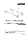
Installation and Maintenance Manual
IM-820
Group: Unitary
Part Number: IM-820
Date: March 2005
Supersedes: New
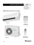
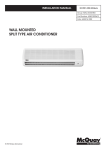
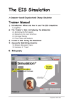
MCM Ceiling/Floor Convertible Split Type Air Conditioner
Indoor Unit
Wireless Remote
Control (Standard)
Outdoor Unit
Wired Wall
Control (Optional)
© 2005 Daikin
IM 820
Page 1
Table of Contents
Model Numbers . . . . . . . . . . . . . . . . . . . . . 2
General Information . . . . . . . . . . . . . . . . . . 3
Safety Precautions ....................................... 3
Unit Dimensions . . . . . . . . . . . . . . . . . . . . 4
Indoor Units .................................................. 4
Outdoor Units ............................................... 4
Installation Guidelines . . . . . . . . . . . . . . . 5
Installation Diagram ..................................... 5
Installation of Outdoor Unit ........................... 5
Installation of the Indoor Unit ....................... 6
General . . . . . . . . . . . . . . . . . . . . . . . . . . . . 6
Indoor Unit Clearances . . . . . . . . . . . . . . . . 6
Standard Mounting . . . . . . . . . . . . . . . . . . . 7
Semi-enclosed Mounting . . . . . . . . . . . . . . 7
Refrigerant Tubing . . . . . . . . . . . . . . . . . . 8
Tubing Length & Elevation . . . . . . . . . . . . . 8
Tubing Preparation . . . . . . . . . . . . . . . . . . . 8
Tubing Connection To Units . . . . . . . . . . . . 8
Electrical Connections . . . . . . . . . . . . . . . 9
Wiring Diagrams . . . . . . . . . . . . . . . . . . . 10
Evacuating and Charging . . . . . . . . . . . . 17
Evacuating the tubing and the indoor unit . 17
Additional charge . . . . . . . . . . . . . . . . . . . .17
Charge operation . . . . . . . . . . . . . . . . . . . . 17
Remote Controller Operation Guide . . . .18
Netware 2 - Wired Wall Control (Optional) 19
Special Features . . . . . . . . . . . . . . . . . . . .20
Dry mode . . . . . . . . . . . . . . . . . . . . . . . . . .20
Heat mode (heat pump only) . . . . . . . . . . .20
Overheating protection (heat pump only) . .20
Frost prevention . . . . . . . . . . . . . . . . . . . . .20
Fan speed and rated cooling capacity . . . .20
Operating Conditions ................................. 20
Cooling . . . . . . . . . . . . . . . . . . . . . . . . . . . .20
Overall Checking . . . . . . . . . . . . . . . . . . . .20
Unit Indicator Lights . . . . . . . . . . . . . . . . 21
IR signal receiver . . . . . . . . . . . . . . . . . . . .21
Netware 2 - Wired Wall Control (Optional) .21
Service and Maintenance . . . . . . . . . . . . 22
Electrostatic Filters . . . . . . . . . . . . . . . . . . 22
Filter Replacement . . . . . . . . . . . . . . . . . . .22
Startup After Extended Shutdown . . . . . . .22
Troubleshooting . . . . . . . . . . . . . . . . . . . . .22
Service and Maintenance . . . . . . . . . . . . . .23
Model Numbers
Cooling Only
Indoor Unit
MCM20D
MCM25D
MCM30D
MCM40D
MCM50D
Outdoor Unit
MLC20B
MLC25B
MLC30C
MLC40C
MLC50C
Nominal Cooling - BTUH
20,000
25,000
30,000
40,000
50,000
Cooling/Heat Pump
Indoor Unit
MCM20DR
MCM25DR
MCM30DR
MCM40DR
MCM50DR
Page 2
Outdoor Unit
MLC20BR
MLC25BR
MLC30CR
MLC40CR
MLC50CR
Nominal Cooling - BTUH
20,000
24,000
30,000
40,000
50,000
Nominal Heating - BTUH
21,000
25,000
32,000
41,000
48,000
IM 820
General Information
This manual provides the installation procedures so
your air conditioner unit operates properly and provides you the service it was designed to provide.
Special adjustment may be necessary to suit local
requirements. Before using your air conditioner,
please read this instruction manual carefully and
keep it for future reference.
CAUTION
Use copper conductors only. Unit terminals are not
designed to accept other types of conductors. Failure to
do so can cause damage to the equipment.
Safety Precautions
Before installing the air conditioner unit, please read the following safety precautions carefully..
WARNING
•
The installer must determine and follow all applicable
codes and regulations. This equipment presents hazards
of electricity, rotating parts, sharp edges, heat and
weight. Failure to read and follow these instructions
can cause property damage, equipment damage, severe
personal injury or death. This equipment must be
installed by experienced, trained personnel only.
•
Do not allow flammable fumes near unit or areas sharing ventilation.
•
Installation and maintenance must be performed by
qualified persons who are familiar with local code and
regulation, and experienced with this type of appliance.
•
All field wiring must be done in accordance with
industry standards and local codes.
•
Inspect the unit nameplate to be certain the voltage is
the same as the voltage that will be delivered to the
unit. Improper electrical wiring can cause property
damage, sever personal energy or death.
•
The unit must be GROUNDED.
•
Make sure wiring does not touch refrigerant piping,
compressor, or any moving parts of the fan motors.
•
Confirm that the power supply is switched OFF before
installing or servicing the unit.
WARNING
Hazardous Voltage!
Disconnect all electrical power including remote
disconnects before servicing. Failure to disconnect
power before servicing can cause severe personal
injury or death.
IM 820
CAUTION
•
Do not install in a laundry room. Humidity and laundry
chemicals can corrode unit components.
•
Do not install the unit where leakage of flammable gas
may occur. If gas leaks and accumulates around the
unit, it can cause a fire.
•
Connect drainage piping properly. If drainage piping is
not connected properly, water leakage can cause property damage.
•
Do not overcharge the unit. This unit is factory precharged. Overcharge will cause over-current or damage
to the compressor.
•
Keep panel closed. Unsecured panels will cause the
unit to operate noisily.
NOTICE
This product was carefully packed and thoroughly
inspected before leaving the factory. Responsibility for
its safe delivery was assumed by the carrier upon
acceptance of the shipment. Claims for loss or damage
sustained in transit must therefore be made upon the
carrier, as follows:
VISIBLE LOSS OR DAMAGE
Any external evidence of loss or damage must be noted
on the freight bill or carrier’s receipt, and signed by the
carrier’s agent. Failure to adequately describe such
external evidence of loss or damage may result in the
carrie’s refusing to honor a damaged claim. The form
required to file such a claim will be supplied by the
carrier.
CONCEALED LOSS OR DAMAGE
Concealed loss or damage means loss or damage
which does not become apparent until the product has
been unpacked. The contents may be damaged in
transit due to rough handling even though the carton
may not show external damages. When the damage is
discovered upon unpacking, make a written request for
inspection by the carrier’s agent within fifteen (15)
days of the delivery date. File a claim with the carrier
since such damage is the carrier’s responsibility.
Page 3
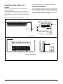
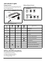
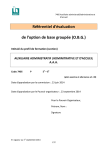
Unit Dimensions
Indoor Units
A
Two mounting brackets
shipped attached to the
indoor unit. See page 7
for more detail.
B
C
E
D
Model MCM
A
B*
C
D
E
F
G
H
20D/DR
46 1/4"
42 1/2"
47 3/4"
26 1/2"
6 1/4"
2 1/4"
20 1/2"
22"
25D/DR
46 1/4"
42 1/2"
47 3/4"
26 1/2"
6 1/4"
2 1/4"
20 1/2"
22"
F
G H
30D/DR
46 1/4"
42 1/2"
47 3/4"
26 1/2"
6 1/4"
3 3/4"
20 1/2"
22"
40D/DR
66"
62 1/4"
67 1/2"
26 1/2"
6 1/4"
3 3/4"
20 1/2"
22"
50D/DR
66"
62 1/4"
67 1/2"
26 1/2"
6 1/4"
3 3/4"
20 1/2"
22"
*Discharge air opening width.
Outdoor Units
A
E
B
C
D
Model MLC
A
B
C
D
E
Page 4
20 & 25 B/BR
16"
33"
25 1/2"
2 1/4"
13 1/4"
30,40 & 50C/CR
19 1/4"
40 1/2"
33 1/2"
3 1/2"
15 3/4"
IM 820
Installation Guidelines
Installation Diagram
INDOOR UNIT
Air Discharge Swing Baffle
IR Receiver and
LED Indicator Lights
Air Discharge Grille
Air Intake Grille
Optional Wired
Wall Control
Air Filters
Refrigerant Tubing
and Insulation
Wireless IR
Remote Control
Air Intake
Air Intake
Air Discharge Nozzle
OUTDOOR UNIT
Installation of Outdoor Unit
Install the outdoor unit in a manner to prevent mixing hot
discharged air with return air flow. Also, the unit should be a
suitable distance from obstructions See Figure 1 for minimum installation clearances. Double the dimensions shown if
surroundings are more than 72" tall, or if there is an obstruction on top. Select the coolest possible place where intake air
temperature is not greater than the outside air temperature
(maximum 113°F). See Table 1, Page 7 for weight of outdoor
unit.
Figure 1. Outdoor Unit Minimum Clearances
40"
Min.
Min.
Air
Intake
Air
Discharge
12"
20"
Min.
Min.
Air
Intake
IM 820
12"
Service
Access
Page 5
Installation of the Indoor Unit
Locate the installation for convenient wiring and piping.
General
Indoor Unit Clearances
Electrical supply and installation must conform to local
codes and regulations.
The indoor unit must be installed in a manner to prevent mixing
the cool discharged air with the hot return air. Follow the installation clearances shown in Figure 2. Do not place the indoor unit
in direct sunlight. The location must be suitable for piping and
drainage, and be away from doors or windows.
Voltage supply fluctuation must not exceed ±10% of the
rated voltage. Electricity supply lines must be independent of
welding transformers which can cause high supply fluctuation.
Figure 2. Indoor Unit Minimum Clearances
.1/2" min.
12"
min.
19.68"
10" max.*
*Appliances, furniture or built-in
architectural features must not
extend more than 10".
CEILING MOUNT
16" min.
40" min.
WALL/FLOOR MOUNT
Page 6
IM 820
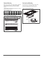
Standard Mounting
Semi-enclosed Mounting
Make sure the ceiling or wall is strong enough to support the
weight of the unit (See Table 1). Remove the mounting
brackets from the unit and secure to wall or ceiling as
required.
In case the unit is to be half-recessed into a false ceiling,
make sure the unit is well-aligned with the ceiling.
The unit must be level front to back and sloped 1/8" towards
condensate drain (See Figure 3).
Figure 4. Semi-enclosed Mounting
Provide the installation space as shown in Figure 4.
12" min.
Table 1: Unit Weight - lbs.
Model
20
25
30
40
50
Weight ID Unit
95
99
99
154
154
Weight OD Unit
125
128
209
220
231
48" min.
1/2" min.
23"
12" min.
Figure 3. Slope for condensate drainage
Top Panel of Unit
1/2"
1/8"
Ceiling Mount
Slope
Wall/Floor Mount
Slope
IM 820
22"
1/2"
Mounting Surface
Ceiling Board
6.3/4"
1/2"
Page 7
Refrigerant Tubing
Tubing Length & Elevation
•
Copper tubing to connect the indoor and outdoor units is supplied by others or it can be ordered from the factory. See
Table 2 and Figure 5 for requirements.
Remove burrs from cut ends by holding tubing downwards to prevent metal chips from entering the tubing.
•
Slide the flare nuts, for both the indoor unit and outdoor
unit onto the copper tubing.
Table 2: Refrigeration Tubing Requirements
•
Flare the tubing as shown in Figure 6 and Table 3.
•
The flare must be even and not cracked or scratched.
Model
20
25
30
40
50
Maximum Length, ft.
49’
49’
115’
115’
115’
Max. elevation, ft, H
26’
26’
49’
49’
49’
Figure 6. Cutting and Flaring Tube
Max. number of bends
10
10
10
10
10
Cutting Copper Tube
Liquid tube size - OD
1/4"
3/8"
3/8"
3/8"
3/8"
Gas tube size - OD
5/8"
5/8"
5/8"
3/4"
3/4"
1/4 Tube
Note: The refrigerant pre-charged in the outdoor unit is for tubing length up to 25
ft. See Table 7 for additional R-22 refrigerant required on runs longer than 25 ft.
Figure 5. Tubing length and elevations
Copper Tube
Indoor Unit
See Table 3
Outdoor Unit
Tubing Length
Flaring Tool
X
Elevation
Table 3: Tube Flaring Dimensions
Tube Diameter - OD
Outdoor Unit
Inch
Imperial
Rigid
1/4
.051
.028
3/8
.063
.039
5/8
.087
.067
Tubing Connection To Units
Tubing Length
Elevation
X (in.)
•
Connect the copper tubing to both the indoor and outdoor
units (See Figure 7).
•
Torque each flare nut to specifications (See Table 4).
•
Cover both tubes individually with 3/8" wall foam insullation.
Figure 7
Flared Tube
Indoor Unit
Tubing Preparation
•
•
•
Do not use contaminated or damaged copper tubing. Do
not remove plastic, rubber plugs or brass nuts from the
valves, fittings, tubings and coils until you are ready to
connect suction or liquid line into valves or fittings.
If any brazing work is required, ensure that the nitrogen
gas is passed through coil and joints while the brazing
work is done. This will eliminate soot formation on the
inside wall of the copper tubing.
Unit Fitting
Flare Nut
Table 4:
Tube Size (in.)
Torque (ft./lb.)
1/4
13.3
3/8
31.0
5/8
48.0
Cut the copper tubing with a tube cutter (See Figure 6).
Page 8
IM 820
Electrical Connections
WARNING
Improper installation can cause severe personal injury
o r death . Wi rin g mu st b e d one by a qual ifi ed
technician in compliance with local codes.
•
•
•
Wiring must be in accordance with all applicable electrical codes.
Wires must not touch the refrigerant piping, compressor
or any moving part.
All electrical field wiring must be clamped at both the
indoor unit and the outdoor unit.
Note:
•
•
Field install 10A fuse in outdoor unit as shown in
wire diagrams for unit sizes 30, 40, and 50.
See Table 5, and 6 for the number of wires, wire gage and
fuse/circuit breaker size required.
NEC requires an approved electrical disconnect within
sight of the unit so that anyone working on the unit can
turn off the power and see that its not accidently turned
back on. This will require two disconnects, one by the
outdoor unit and one by the indoor unit.
IM 820
Table 5: Wire, Fuse/Breaker Requirements - Cooling
Only
Unit Size
20
25
Voltage - 60Hz. 1 Ph.
Power supply wire size
30
40
50
208/230
12 ga.
10 ga.
8 ga.
8 ga.
6 ga.
No. of 12 ga. wires
between units
2 + gnd.
2 + gnd
3 + gnd
3 + gnd
3 + gnd
Fuse/Breaker size
20 amp.
25 amp.
35 amp.
40 amp.
55 amp.
Table 6: Wire, Fuse/Breaker Requirements - Heat
Pump Only
Unit Size
20
25
Voltage - 60Hz. 1 Ph.
Power supply wire size
30
40
50
208/230
12 ga.
10 ga.
8 ga.
8 ga.
6 ga.
No. of 12 ga. wires
between units*
4 + gnd.
4 + gnd
6 + gnd
6 + gnd
6 + gnd
Fuse/Breaker size
20 amp.
25 amp.
35 amp.
40 amp.
55 amp.
* Not including the low voltage OD coil sensor cable.
Page 9
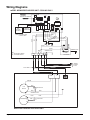
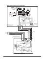
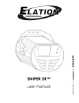
Wiring Diagrams
MODEL MCM20D/25D INDOOR UNIT- COOLING ONLY
RETURN AIR SENSOR
ROOM
JH
INDOOR COIL SENSOR
ID
OD
CN4
CN6
TRANSFORMER
L
WIRELESS
REMOTE
CONTROLLER
COMP.
HIGH
WIRED
WALL
CONTROL
(OPTIONAL)
LOW MED
AS
BLUE
RED
WHITE
NOTE: DISCONNECT CN6
IF CN4 IS USED
N2
LIVE
N1
WHITE
BLUE
YELLOW
BLACK
RED
FH
FM
FL
G/Y
RED
WHITE
BROWN
AS
BLACK
BLACK
BLACK
AC
GREEN/YELLOW
IC
GREEN/YELLOW
MC
KEY:
---- - FIELD SUPPLY WIRING
AS - AIR SWING MOTOR
COMP. L
N
N
FAN MOTOR
L2
L1
}
208/230V
1 PHASE
60Hz
12 GA. WIRE
COMP
N
BROWN
RED
FAN
MOTOR
CAPACITOR
BLUE
BLUE
GREEN/YELLOW
BLUE
C
COMPRESSOR
S
R
RED
BLUE
CAPACITOR
WHITE
MODEL MLC20B/25B OUTDOOR UNIT
Page 10
IM 820
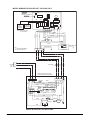
MODEL MCM 030D INDOOR UNIT- COOLING ONLY
RETURN AIR SENSOR
ROOM
INDOOR COIL SENSOR
ID
OD
CN4
CN6
TRANSFORMER
L
WIRELESS
REMOTE
CONTROLLER
COMP.
AS
N2
HIGH
WIRED
WALL
CONTROL
(OPTIONAL)
LOW MED
N1
LIVE
FH
WHITE
BLUE
YELLOW
RED
FM
FL
BLACK
RED
RED
WHITE
NOTE: DISCONNECT CN6
IF CN4 IS USED
BLUE
208-230V
1 PH
60HZ
{
A.C.
GREEN/YELLOW
KEY:
---- - FIELD SUPPLIED WIRING
AS - AIR SWING MOTOR
BROWN
BLACK
RED
BLACK
AS
BLACK
I.C.
GREEN/YELLOW
MC
COMP. L
N
FAN MOTOR
12 GA. WIRE
L2
L1
N
CAP.
S
R
COMP.
RED
G/Y
*10A
RED *10A
HIGH / LOW
PRESSURE SWITCH
RED
REDREDRED
A
C
R/L1S/L2 T/L3 A1
MAGNETIC
1
CONTACTOR
2
U/T1V/T2 W/T3 A2 BLUE
REDRED
BLACK
N
L
BLUE
BLUE
RED
RED
RED
BLUE
BLUE
BLUE
BLACK
GREEN/YELLOW
L
WHITE
WHITE
*NOTE: FIELD INSTALL 10A FUSE
IN BLUE AND RED WIRE AS SHOWN
WHITE
RED
WHITE
RED
R
S
RED
BROWN
C
FAN
G/Y
COMPRESSOR CRANKCASE
MOTOR
HEATER
BROWN
MODEL MLC30C OUTDOOR UNIT
IM 820
Page 11
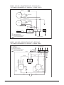
MODEL MCM40D/50D INDOOR UNIT- COOLING ONLY
RETURN AIR SENSOR
ROOM
INDOOR COIL SENSOR
ID
CN4
CN6
TRANSFORMER
L
WIRELESS
REMOTE
CONTROLLER
COMP.
N2
HIGH
WIRED
WALL
CONTROL
(OPTIONAL)
LOW MED
AS
LIVE
N1
FH
WHITE
BLUE
YELLOW
RED
RED
PURPLE
NOTE: DISCONNECT CN6
IF CN4 IS USED
RED
FM
FL
BLUE
WHITE
BLACK
RED
AS
BLACK
A.C.
GREEN/YELLOW
KEY:
---- - FIELD SUPPLIED WIRING
AS - AIR SWING MOTOR
{
208-230V
1 PH
60Hz
I.C.
GREEN/YELLOW
MC
COMP. L/L1
N/L2
FAN MOTOR
12 GA. WIRE
L2
L1
*NOTE: FIELD INSTALL 10A FUSE
IN BLUE AND RED WIRE AS SHOWN
COMP. L/L1 N/L2
BLUE
GREEN/YELLOW
BLACK PURPLE
RED
*10A FUSE
BLUE
*10A FUSE
RED 8
REDRED RED
1L1 3L2 5L3 1
2T1 4T2 6T3 2
REDRED
7
BLUE
A1 RED
6
A2
2
LOCK OUT
RELAY
RED
PURPLE
BLUE BLACK
HIGH
PRESSURE
SWITCH
LOW
PRESSURE
SWITCH
BLUE
RED
GREEN/YELLOW
L/L1 N/L2
BLUE
BLACK
WHITE
RED
RED
RED
BLUE
BROWN
C
FAN
G/Y
COMPRESSOR CRANKCASE
MOTOR
HEATER
BROWN
R
S
RED
BLUE
WHITE
MODEL MLC40C/50C OUTDOOR UNIT
Page 12
IM 820
MODEL MCM20DR/25DR INDOOR UNIT - HEAT PUMP
RETURN AIR SENSOR
ROOM
JH
INDOOR COIL SENSOR
RMODE
CN3
ID
OD
CN4
CN6
TRANSFORMER
L
N1
BLUE
FH
WHITE
BLUE
YELLOW
RED
RED
WHITE
BROWN
BLUE
NOTE: DISCONNECT CN6
IF CN4 IS USED
N2
LIVE
RED
AS
HIGH
WTP
4WV
DDH
COMP.
LOW MED
BLACK
WIRELESS
REMOTE
CONTROLLER
WIRED
WALL
CONTROL
(OPTIONAL)
RED
FM
FL
BLUE
G/Y
BLACK
BLACK
BLACK
RED
WHITE
AS
A.C.
GREEN/YELLOW
I.C.
GREEN/YELLOW
MC
4WV OF COMP. L
N
N
FAN MOTOR
KEY:
---- - FIELD SUPPLIED WIRING
AS - AIR SWING MOTOR
4WV - 4 WAY VALVE
L2
L1
LOW VOLTAGE CABLE TO
OUTDOOR COIL SENSOR
208-230V
1 PH
60Hz
12 GA. WIRE
4WV OF COMP.
BLACK
N
BLACK
GREEN/YELLOW
TH2
BLACK
BLUE
GREEN/YELLOW
BROWN
BLUE
WHITE
BLUE
C
CONPRESSOR
RED
MOTOR S
BLUE
RED
FAN
MOTOR
WHITE
BROWN
R
BLUE
BLACK
4V
BLACK
KEY:
---- - FIELD SUPPLIED WIRING
4V - 4 WAY VALVE
TH2 - OUTDOOR THERMISTOR
AS - AIR SWING MOTOR
MOEL MLC20BR/25BR OUTDOOR UNIT
IM 820
Page 13
MODEL MCM 30DR INDOOR UNIT - HEAT PUMP
RETURN AIR SENSOR
ROOM
JH
INDOOR COIL SENSOR
RMODE
CN3
ID
OD
TO OUTDOOR
DEFROST SENSOR
CN4
CN6
TRANSFORMER
L
LOW MED
N1
WHITE
BLUE
YELLOW
RED
RED
WHITE
BROWN
BLUE
LIVE
RED
FH
FM
FL
BLUE
BROWN
AS
NOTE:
DISCONNECT CN6
IF CN4 IS USED:
BLACK
N2
HIGH
4WV
WTP
COMP.
WIRELESS
REMOTE
CONTROLLER
DDH
WIRED
WALL
CONTROL
(OPTIONAL)
RED
BLACK
AS
BLACK
A.C.
KEY:
---- - FIELD SUPPLIED WIRING
AS - AIR SWING MOTOR
4WV - 4 WAY VALVE
N
FAN MOTOR
12 GA. WIRE
L2
L1
A
BLACK
*NOTE: FIELD INSTALL 10A FUSE
IN BLUE AND RED WIRE AS SHOWN
N
RED
4WV
WHITE
BLACK
CRANKCASE
HEATER
C
BLACK
WHITE
BLUE
HIGH
PRESSURE
SWITCH
BROWN
A2
L
G/Y
BROWN
A1
COMP.
WHITE
*10A FUSE
WHITE
WHITE
BLUE
22 T1 T2 T3 14
REDRED
WHITE
WHITE
O/D COIL SENSOR
REDREDRED
21 L1 L2 L3 13
OF
BLUE
GREEN/YELLOW
RED
4WV
*10A FUSE
BLACK
BLUE
BLUE
N
RED
L
BLACK
{
GREEN/YELLOW
MC
A 4WV OF COMP. L
LOW VOLTAGE CABLE TO
OUTDOOR COIL SENSOR
208-230V
1 PH
60Hz
I.C.
GREEN/YELLOW
R
S
RED
BLUE
COMPRESSOR
FAN
MOTOR
MODEL MLC30CR - OUTDOOR UNIT
Page 14
IM 820
MODEL MCM 40DR/50DR INDOOR UNIT
RETURN AIR SENSOR
ROOM
JH
INDOOR COIL SENSOR
RMODE
CN3
ID
OD
TO OUTDOOR
DEFROST SENSOR
CN4
CN6
TRANSFORMER
L
N2
HIGH
WTP
AS
LIVE
N1
WHITE
BLUE
YELLOW
RED
RED
PURPLE
BROWN
BLUE
4WV
DDH
COMP.
LOW MED
RED
FH
FM
FL
BLACK
BROWN
WIRELESS
REMOTE
CONTROLLER
BLACK
AS
WHITE
KEY:
---- - FIELD SUPPLIED WIRING
AS - AIR SWING MOTOR
RED
WIRED
WALL
CONTROL
(OPTIONAL)
BLACK
A.C.
I.C.
GREEN/YELLOW
GREEN/YELLOW
MC
A 4WV OF COMP.L L1 N L2
FAN MOTOR
LOW VOLTAGE CABLE TO
OUTDOOR COIL SENSOR
L2
L1
A
RED
4WV
PURPLE
BLACK
HIGH
PRESSURE
SWITCH
WHITE
BLUE
BROWN
BLUE
G/Y
PURPLE
BLACK
S
RED
C
COMPRESSOR
BLUE
WHITE
A2
CRANKCASE
HEATER
R
BLACK
*10A FUSE
A1
WHITE
2T14T2 6T3 2
REDREDRED
WHITE
BLUE
O/D COIL SENSOR
REDREDRED
1L1 3L2 5L3 1
OF
BLUE
GREEN/YELLOW
RED
4WV
*10A FUSE
BLACK
RED
BLUE
*NOTE: FIELD INSTALL 10A FUSE
IN BLUE AND RED WIRE AS SHOWN
COMP. L L1 N L2
BROWN
L L1 N L2
BLUE
{
208-230V
1 PH
60Hz
12 GA. WIRE
FAN
MOTOR
MODEL MLC40CR/50CR
IM 820
Page 15
MODEL : MLC 20B - 25B OUTDOOR UNIT - COOLING ONLY
- OPTIONAL LOW AMBIENT KIT (208/230V - 1 PHASE - 60HZ)
WHITE
OL
C
RED
S
CM
CAPACITOR
BLUE
R
GREEN/YELLOW
BLUE
BLUE
CAPACITOR
FM
YELLOW
ORANGE
1 2
OUTDOOR COIL SENSOR
3
4
5
COMP
N
FSCM
KEY
CM - COMPRESSOR MOTOR
FM - OUTDOOR FAN MOTOR
FSCM - FAN SPEED CONTROL MODULE
12 GA. FIELD SUPPLIED WIRING
(TO INDOOR UNIT)
MODEL : MLC 20BR - 25BR OUTDOOR UNIT - HEAT PUMP
- OPTIONAL LOW AMBIENT KIT (208/230V - 1 PHASE - 60HZ)
KEY
FM - FAN MOTOR
CM - COMPRESSOR MOTOR
4V - 4 WAY VALVE
TH2 - OUTDOOR THERMISTOR
FSCM - FAN SPEED CONTROL MODULE
12 GA. FIELD SUPPLIED WIRING
(TO INDOOR UNIT)
BLACK
BROWN
N
4V OF COMP.
BLACK
E
BLUE
BLACK
BROWN
BLACK
GREEN/YEL
TH2
BLUE
1
BLUE
WHITE
2
FSCM
ORANGE
BROWN
YELLOW
3
BLACK
E
4
C
RED
RED
S
BLUE
E
BLUE
BLACK
Page 16
CM
WHITE
R
BLACK
FM
4V
BLACK
IM 820
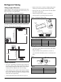
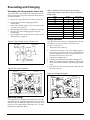
Evacuating and Charging
Evacuating the tubing and the indoor unit
The outdoor unit is pre-charged with refrigerant R-22. The
indoor unit and the refrigerant connection tubing must be
evacuated as follows:
1.
Remove the 3 caps from the valves on the outdoor unit.
2.
Connect the center of the charging gauge to the
vacuum pump.
Connect the charging gauge to the service port of the
3-way valve (See Figure 9).
Start the pump and evacuate to -760 mm Hg (-29.9" Hg).
Close the valve of the changing gauge and stop the
vacuum pump.
On the outdoor unit, open both valves using a 4 mm
Allen wrench (See Figure 8).
3.
4.
5.
6.
Table 7: Additional R-22 ounces per foot of tubing
(when tubing length is more than 25 ft.) and maximum
tubing length.
Model
Oz. Per ft.
Max. Length
20D
.16
49’
25D
.40
49’
30D
.53
115’
40D
.55
115’
50D
.55
115’
20DR
.16
49’
25DR
.50
49’
30DR
.53
115’
40DR
.55
115’
50DR
.55
115’
Charge operation
Figure 8. 3-way Suction Valve on Outdoor Unit
Hex Socket
for 4 mm
Allen wrench
Refrigerant
Tubing
Flare Nut
Service
Port
This operation must be done by weighing the R-22 being
added thru the service port on the 3-way suction valve.
See Table 7 and Figure 10.
1.
Remove the service port cap.
2.
Connect the low pressure side of the charging gauge to
the suction service port center of the cylinder tank and
close the high pressure side of the gauge. Purge the air
from the service hose (See Figure 10).
Start the air conditioner unit.
Open the gas cylinder and low pressure charging valve.
When the required refrigerant quantity is pumped into
the unit, close the low pressure side and the gas cylinder
valve.
Disconnect the service hose from service port. Put back
the service port cap.
3.
4.
5.
Outdoor Unit
3-way Valve
6.
Figure 9 Evacuation Schematic
Outdoor Unit
Indoor Unit
Liquid side
Discharge Valve
Close
Figure 10. Charging Schematic
Outdoor Unit
Indoor Unit
Liquid side
Discharge Valve
Gas side
Suction Valve
Gas side
Close
Vacuum
Pump
Suction Valve
Low
Press.
High
Press.
Low
Press.
High
Press.
Additional charge
The refrigerant is pre-charged in the outdoor unit. If the tubing length between the indoor and outdoor unit is no more
than 25 ft., then an additional charge after evacuation is not
necessary. If the tubing length is more than 25 ft., use additional R-22 as indicated in Table 7.
IM 820
Page 17
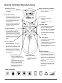
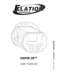
Remote Controller Operation Guide
Transmission source
Signal Transmission Indication
•
•
The source where the signal is
transmitted.
Blinks to confirm the last setting
was sent to the unit.
Temperature Setting
•
Set the desired room temperature
by pressing the buttons to increase
or decrease the set temperature.
On/Off Button
•
Press once to start the air
conditioner.
Press again to stop the air
conditioner.
•
The temperature setting range is
from 60°F to 86°F.
•
•
Press both buttons simultaneously
to toggle the temperature setting
between °C and °F.
Operation mode
Fan Speed Selection
•
Press the button until the desired
fan option displays (auto, low,
med. or high). "Auto" automatically
selects high fan until room temperature is within 2oF of setting, then
switches to low fan. Fan runs continuouse in COOL and cycles in
HEAT.
Press the SET button will activate
the on timer function.
•
Set the desired on time by pressing
the SET button continuously. If the
timer is set to 7.30am, the air conditioner will turn on at 7.30 sharp.
•
Press the CLR button to cancel the
on timer setting.
Press the MODE button to select
the type of operating mode.
•
For cooling only unit, the available
modes are : COOL, DRY & FAN.
•
For heat pump unit, the available
modes are: AUTO, COOL, DRY,
FAN & HEAT.
OFF Timer Setting
ON Timer Setting
•
•
•
Press the SET button will activate
the off timer function.
•
Set the desired off time by pressing
the SET button continuously.
•
Press the CLR button to cancel the
off timer setting.
Sleep mode setting
Automatic Air Swing
•
Press the button to activate sleep
mode. This function is available
under COOL, HEAT & AUTO mode.
•
In COOL mode, the set temperature
will increase 1.0°F after 30 minutes,
2°F after 1 hour and a total of 4°F
after 2 hours.
•
In HEAT mode, the set temperature
will decrease 2°F after 30 minutes,
4°F after 1 hour and a total of 5°F
after 2 hours.
Clock Time Setting
•
Press the SWING button to
activate the automatic air swing
function.
•
To distribute the air to a specific
direction, press the SWING
button and wait until the air
conditioner baffle swings to the
desired direction. Press the
button again to hold it.
•
Press button + or - to
increase or decrease the
clock time.
Symbol Identification
Auto
Cool
Page 18
Dry
Fan
Heat
Sleep
Power
Timer
Auto
low
med
high
Fan Speed
IM 820
Netware 2 - Wired Wall Control (Optional)
Features:
1. Modes - Cool, Heat, Auto, Dry, Fan and Off.
AUTO
SLEEP
DRY AUTO COOL HEAT FAN
SET CLOCK
MON TUE WED THU FRI SAT SUN
ON
AM
PM
OFF
TIME ACTIVATE
SET TIMER
SET CLOCK
COOL
TEMP.
HEAT
TEMP.
ROOM
TEMP.
SWING
˚F
˚C
ON/OFF
FAN
SLEEP
MODE
SET TEMP
SWING
ON TIMER
OFF TIMER
DAY
HOUR
CLOCK
HOLD
IM 820
MINUTE
2.
Temperature Range - 60° F to 86° F. (Press both arrows
simultaneously to convert from °C to °F.)
3. Timer - Seven day clock capable of a different On/Off
time for each day of the week. Note: Hold button is used
to temporarily override timer.
4. Shows time of day.
5. Electronic lockout to prevent tampering.
6. Fan Speeds - Low, medium, high and auto.
7. Sleep - Sets temperature back for sleeping.
8. Swing - Swings or positions air baffle for better air distribution.
9. Display normally shows room temperature. (Momentarily shows set point when a change is made.)
10. Heat symbol (Ã ) blinks while outdoor coil defrosts
(heat pump only).
11. Error codes blink on display:
E1 - Room sensor loose or defective.
E2 - Indoor coil sensor loose or defective.
E3 - Outdoor coil sensor loose or defective.
E4 - Compressor cycling on overload.
E5 - Low refrigerant charge.
For more detail, see manual that ships with the Wall Control.
Page 19
Special Features
Dry mode
•
Heating (heat pump only)
Select this mode when the standard Cool mode does not
provide sufficient dehumidification. The compressor and
indoor low fan will cycle together and will operate for
longer periods of time to provide the increased rate of
dehumidification. As a result, the room temperature differential may increase slightly.
Heat mode (heat pump only)
•
•
Temperature
Ts °F
Th °F
Minimum Indoor
61
—
Maximum Indoor
86
—
Minimum Outdoor
16
21
Maximum Outdoor
75
64
Ts = Dry Bulb Temperature, Th = Wet Bulb Temperature
When the unit is switched on from cold start or defrosting
cycle, the indoor fan will start to operate only after the
coil warms up.
When the set temperature is achieved, the indoor fan will
operate until the coil cools down.
Overall Checking
Ensure that:
1. The unit has been mounted properly.
Overheating protection (heat pump only)
2. Refrigerant tubing connections have been checked for
leaks
•
3. Proper wiring and circuit breakers have been installed.
In case the coil overheats (145°F), the compressor will
cut out.
Frost prevention
•
If the indoor coil starts to frost, an LED light will blink to
indicate that the unit is in defrost.
Fan speed and rated cooling capacity
•
The rated cooling capacity is provided at high indoor fan
speed.
•
The cooling capacity is slightly lower when the unit is
operating at MEDIUM and LOW fan speed.
Operating Conditions
Cooling
Temperature
Ts (dry bulb) °F
Th (wet bulb) °F
Minimum Indoor
61
52
Maximum Indoor
90
73
Minimum Outdoor
66*
24
Maximum Outdoor
114
75
Drainage check:
Check condensate drain for leaks and proper flow.
Test run:
Check the following items:
• Are all electrical plugs firmly inserted into there receptcales?
• Is there any abnormal sound from the unit?
• Is there any abnormal vibration on the unit itself or piping?
Confirm that:
1. Condenser fan is running, with warm/cold air blowing off
the outdoor unit. (Cooling only/Heat Pump)
2. Evaporator blower is running and discharge cool/warm air.
(Cooling only/Heat Pump)
Note:
The control incorporates a 3 minute randum start
delay in the circuit. Thus, it requires about 3 minutes
before the outdoor unit will start.
* 32°F on size 20 and 25, 23°F on size 30, 40 and 50 with optional Low Ambient
Kit.
Page 20
IM 820
Unit Indicator Lights
IR signal receiver
Wireless Remote Control
When an infrared remote control operating signal is transmitted, the indoor unit beeps and indicator lights confirm acceptance of the signal transmission.
Figure 12. LED Indicator Lights Display
Cooling Unit
Figure 11. IR Receiver & LED Indicator Lights Location
INDOOR UNIT
Air Discharge
Swing Baffle
IR Receiver
and LED
Indicator Lights
Air Discharge
Grille
Air Filters
Air Intake Grille
Optional Wired
Wall Control
Cool
Dry
Fan
Cool
Dry
Fan
Heat
Wireless Remote
Control
Figure 13: Mode and Diagnostic Chart
Mode or Fault
Cool
Dry
Fan
Heat
Cooling mode
Dry mode
Fan mode
Heat mode
Auto mode in heating operation.
Auto mode in cooling operation.
Defrost operation
Compressor overload protection
Outdoor coil sensor contact loose/short
Room air sensor contact loose/short
ON
Blinking
Netware 2 - Wired Wall Control (Optional)
Error codes blink on wall control display as follows:
E1 - Room sensor loose or defective.
E2 - Indoor coil sensor loose or defective.
E3 - Outdoor coil sensor loose or defective.
E4 - Compressor cycling on overload.
E5 - Low refrigerant charge.
IM 820
Page 21
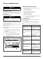
Service and Maintenance
WARNING
Disconnect the electrical power supply before performing
any service, maintenance or troubleshooting.
Electrostatic Filters
Pre-charged electrostatic polypropylene filter removes
microscopic dust, smoke and small invisible particles to keep
the room air clean.
Filter Replacement
Startup After Extended Shutdown
•
Inspect thoroughly and clean indoor and outdoor units.
•
Clean or replace air filter.
•
Clean condensate drain line.
•
Clean clogged indoor and outdoor coils.
•
Check fan imbalanced before operation.
•
Tighten all wire connections.
•
Check for refrigerant leakage.
Note:
WARNING
Disconnect the main power supply before opening the
return air grille.
DO NOT restore power until the grille is closed.
The crankcase heater should be energized for at least
6 hours before starting the unit.
Troubleshooting
If any malfunction of the unit is noted, immediately switch
off the power supply.
See Figure 14.
Check the following chart for possible causes/treatments.
Replace the electrostatic air purifying filters every 6 months
or sooner if they turn brown.
If the trouble persists, please call your local dealer/serviceman.
Replacement filters can be purchased from your sales representative or distributor.
Use the new filter immediately once it has been removed
from the package.
1.
Open the return air grilles and remove the filters.
2.
Use a vacuum cleaner or wash with water with a neutral
cleaning agent.
Rise and dry before installing the filter.
3.
Note:
Trouble
The compressor does not
operate.
Possible cause/treatment
Protection against frequent
starting. Wait for 3 to 4 minutes
for the compressor to start
operating.
Power failure.
Check fuse or circuit breaker.
Fans and compressor do not
operate.
Never use chemicals such as gasoline or paint thinner to clean the filters. Filters will be damaged.
Power supply disconnect off.
Delay timer may be set
incorrectly.
Dirty air filters.
Figure 14. Changing the Filters
Air flow too low or insufficient
cooling/heating capacity.
Doors or windows open.
Adjust thermostat setting.
Discharge air flow has
bad odor.
Smoke, perfume, etc. may
have collected on the indoor
coil.
Clean coil.
Use dry mode. High humidity
in conditioned space.
Condensation on the return air
grille of the indoor unit.
Page 22
Set temperature too low.
Increase temperature setting
and operate unit at high fan
speed.
Condensate leaking into room.
Condensate drain plugged.
Hissing sound from the unit
during operation.
Refrigerant fluid flowing into
the evaporator coil. Operate
for a while to see if sound goes
away.
IM 820
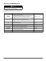
Service and Maintenance
WARNING
Disconnect the main power supply before performing any
service, maintenance or troubleshooting.
The unit is designed to give long life operation with minimum maintenance required. However, it should be regularly
checked and the following items should be given due attention.
Item
Maintenance Procedures
Frequency
Indoor Unit
Air Filters
1. Remove the filter before cleaning it.
2. Remove the dust adhering on the filter by using a vacuum cleaner or wash
with lukewarm water (below 40°C/104°F) with neutral detergent solution.
At least once a month.
3. Rinse well and dry the filter before placing it back onto the unit.
Note. Do not use gasoline, volatile substances or chemicals to clean the
filter.
Indoor Unit
Clean the grille and panel by wiping it using soft cloth soaked in lukewarm
water (below 40°C/104°F) with neutral detergent solution.
Note. Do not use gasoline, volatile substances or chemicals to clean the
unit.
Every year.
Check and clean if necessary.
Every year.
Condense Drain Pan and
Pipe
Indoor Fan
Indoor/Outdoor Coil
Power Supply
Compressor
Compressor Oil
Fan Motor Oil
IM 820
.
Check for abnormal noise.
Every year.
Clean the louvers and coil. Be careful not to bend or flatten the aluminium fins.
DO NOT use cleaning fluids that might corrode the coil.
Every year.
1. Check the running current and voltage for indoor and outdoor units.
2. Check the electrical wiring and tighten the terminals.
Every year.
No maintenance needed if refrigerant circuit remains sealed. However, check
for refrigerant leaks at joints and fittings.
Every year.
Oil is factory charged. Not necessary to add oil if circuit remains sealed.
No maintenance required.
All motors are pre-lubricated and sealed at factory.
No maintenance required.
Page 23
This document contains the most current product information as of this printing. For the most up-to-date
product information, please go to www.DaikinApplied.com.
Daikin Applied
800.432.1342
www.DaikinApplied.com
© 2004 Daikin