1
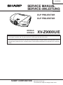
XV-Z9000U/E
SERVICE MANUAL
SERVICE-ANLEITUNG
S81Y7XVZ9000U
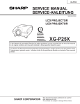
DLP PROJECTOR
DLP PROJEKTOR
MODELS
MODELLE
XV-Z9000U/E
In the interests of user-safety (Required by safety regulations in some countries) the set should be restored
to its original condition and only parts identical to those specified should be used.
Im lnteresse der Benutzersicherheit (erforderliche Sicherheitsregeln in einigen Ländern) muß das Gerät in seinen
Originalzustand gebracht werden. Außerdem dürfen für die spezifizierten Bauteile nur identische Teile verwendet
werden.
SHARP CORPORATION
This document has been published to be used for
after sales service only.
1The contents are subject to change without notice.
XV-Z9000U/E
CONTENTS
Page
•
•
•
•
•
•
•
•
•
•
•
•
•
Page
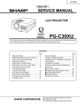
SPECIFICATIONS ............................................. 3
INPOTANT SERVICE SAFETY NOTES ............ 4
OPERATION MANUAL ...................................... 8
REMOVING OF MAJOR PARTS ..................... 14
RESETTING THE TOTAL LAMP TIMER ......... 20
THE OPTICAL UNIT OUTLINE ........................ 21
ELECTRICAL ADJUSTMENT .......................... 24
TROUBLE SHOOTING TABLE ........................ 32
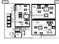
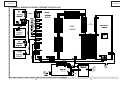
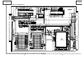
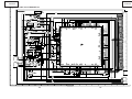
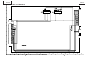
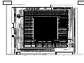
CHASSIS LAYOUT .......................................... 92
BLOCK DIAGRAM ........................................... 94
OVERALL WIRING DIAGRAM ........................ 96
DESCRIPTION OF SCHEMATIC DIAGRAM ... 98
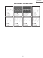
WAVEFORMS .................................................. 99
• SCHEMATIC DIAGRAM ................................
• PRINTED WIRING BOARD ASSEMBLIES ...
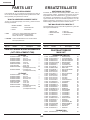
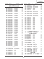
• PARTS LIST
Ë ELECTRICAL PARTS ...............................
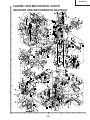
Ë CABINET AND MECHANICAL PARTS ....
Ë ACCESSORIES PARTS ...........................
Ë PACKING PARTS .....................................
• PACKING OF THE SET .................................
100
133
140
154
158
158
159
INHALT
Seite
• TECHNISCHE DATEN .....................................
• HINWEISE FÜR DAS
WARTUNGSPERSONAL .................................
• BEDIENUNGSANLEITUNG .............................
• ENTFERNEN DER HAUPTTEILE ...................
• RÜCKSTELLEN DES
LAMPENBETRIEBSZEIT-TIMERS ..................
• BESCHREIBUNG DER OPTIK-EINHEIT ........
• ELEKTRISCHE EINSTELLUNG ......................
• FEHLERSUCHTABELLE .................................
• CHASSIS-ANORDNUNG ................................
• BLOCKSCHALTBILD .......................................
• GESAMTSCHALTPLAN ...................................
Seite
49
• BESCHREIBUNG DES SCHEMATISCHEN
SCHALTPLANS ............................................... 98
• WELLENFORMEN ........................................... 99
• SCHEMATISCHER SCHALTPLAN ................ 100
• LEITERPLATTENEINHEITEN ....................... 133
• ERSATZTEILLISTE
Ë ELEKTRISCHE BAUTEILE ...................... 140
Ë CEHÄUSE UND MECHANISCHE
BAUTEILE ................................................ 154
Ë ZUBEHÖRTEILE ...................................... 158
Ë VERPACKUNGSTEILE ............................ 158
• VERPACKEN DES GERÄTS ......................... 159
50
51
57
63
64
67
75
92
94
96
2
XV-Z9000U/E
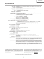
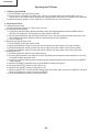
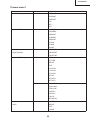
Specifications
Product type
Model
Video system
Computer
Display method
DMD panel
Lens
Projection lamp
Contrast ratio
Video input signal
S-video input signal
Component input signal
Horizontal resolution
DC output
Computer RGB input signal
Wired Remote Control
Pixel clock
Vertical frequency
Horizontal frequency
Computer control signal
Rated voltage
Input current
Rated frequency
Power consumption
Operating temperature
Storage temperature
Cabinet
I/R carrier frequency
Dimensions (approx.)
Weight (approx.)
Supplied accessories
Replacement parts
DLP Projector
XV-Z9000U/E
PAL/PAL 60/PAL- M/PAL- N/SECAM/NTSC 3.58/NTSC 4.43/DTV 480I/DTV 480P/DTV 720P/DTV 1080I
VGA/SVGA/XGA/SXGA
Single panel Digital Micromirror Device™(DMD™) by Texas Instraments
Panel size:0.8" (20.3mm)
No.of dots:921,600 dots (1280 [H ] X 720 [V ])
1 – 1.35X zoom lens, F3, f = 32.5 – 44.0 mm
250 W NSH lamp
1000:1
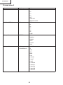
RCA Connector:VIDEO,composite video,1.0 Vp-p,sync negative,75 Ω terminated (INPUT 4)
4-pin Mini DIN connector (INPUT 3)
Y (luminance signal):1.0 Vp-p,sync negative,75 Ω terminated
C (chrominance signal):Burst 0.286 Vp-p,75 Ω terminated
RCA connector (INPUT 1 and 2 terminals)
Y:1Vp-p, sync negative, 75 Ω terminated
PB/PR:0.7Vp-p, 75 Ω terminated (XV-Z9000U)
CB/CR:0.7Vp-p, 75 Ω terminated (XV-Z9000E)
720 TV lines (DTV 720P input)
12V. MAX CURRENT 200mA CENTER + TYPE
15-PIN MINI D-SUB CONNECTOR (INPUT 5 port):
RGB separate/composite sync/sync on green type analog input:0 – 0.7 Vp-p,positive,
75 Ω terminated
HORIZONTAL SYNC.SIGNAL:TTL level (positive/negative)or composite sync (Apple only)
VERTICAL SYNC.SIGNAL:Same as above
3.5 ø Mini jack
12 – 120MHz
43 – 100Hz
15 – 80 kHz
9-pin D-Sub male connector (RS-232C port)
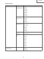
AC 100 – 240 V
3.6 A
50/60 Hz
345 W (Selecting "BRIGHT" in the "Theater Mode".)
+ 5 °C to + 35 °C (41 °F to + 95 °F )
− 20 °C to + 60 °C (− 4 °F to + 140 °F)
Plastic
38 kHz
18 11⁄16" (W) X 7" (H) X 15 15⁄50" (D)(475 X 178 X 406mm)(main body only)
18 11⁄16" (W) X 8" (H) X 19 1⁄2" (D)(475 X 203 X 496 mm)(including terminal cover and
adjustment feet)
20.9 lbs.(9.5 kg)
Remote control, Two AA size batteries, Power cord (11' 10" ,3.6 m(XV-Z9000U), 1.8m(XV-Z9000E)),
Lens cap (attached), DLP projector operation manual, CD-ROM, CD-ROM operation manual,
Terminal cover, Video cable(XV-Z9000E), VGA cable(XV-Z9000E), 21pin-RCA adaptor(XVZ9000E), Guarrantee card for U.S., Guarrantee card for CANADA.
Lamp unit (Lamp/cage module) (BQC-XVZ9000/1), Remote control (RRMCG1657CESA), AA size
batteries, Power cord (CACCU5013DE01 (XV-Z9000U), QACCV4002CEZZ (XV-Z9000E),
QACCB5024CENA (XV-Z9000E)), Lens cap (PCAPH1056CESA),DLP projector operation manual
(TINS-7415CEZZ (XV-Z9000U), TINS-7521CEZZ (XV-Z9000E)), CD-ROM(UDSKA0047CEN1),
CD-ROM operation manual (TINS-7418CEZZ (XV-Z9000U), TINS-7523CEZZ (XV-Z9000E)), Video
cable(QCNWGA001WJZZ(XV-Z9000E)), VGA cable(QCNW-5050CEZZ(XV-Z9000E)), 21pin-RCA
adaptor(QSOCZ0361CEZZ(XV-Z9000E)), Guarrantee card for U.S.(TGAN-1670CEZZ),
Guarrantee card for CANADA (TGAN-1671CEZZ).
This unit has some inactive pixels within acceptable tolerances which
may result in inactive dots on the picture screen.This will not affect
the picture quality or the life expectancy of the unit.
If you have any questions about this matter,please call toll free 1888-GO-SHARP (1-800-237-4277). U.S.A.ONLY
This SHARP projector uses a DMD panels.This very sophisticated
panels contain 921,600 pixels. As with any high technology electronic equipment such as large screen TVs,video systems and video
cameras, there are certain acceptable tolerances that the equipment must conform to.
Specifications are subject to change without notice.
3
XV-Z9000U/E
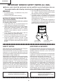
IMPORTANT SERVICE SAFETY NOTES (for USA)
Ë Service work should be performed only by qualified service technicians who are
thoroughly familiar with all safety checks and servicing guidelines as follows:
» Use an AC voltmeter with sensitivity of 5000 ohm per
volt., or higher, sensitivity to measure the AC voltage
drop across the resistor (See Diagram).
» All checks must be repeated with the AC plug
connection reversed. (If necessary, a non-polarized
adapter plug must be used only for the purpose of
completing these checks.)
Any reading of 0.3 volts RMS (this corresponds to
0.2 milliamp. AC.) or more is excessive and indicates
a potential shock hazard which must be corrected
before returning the unit to the owner.
WARNING
1. For continued safety, no modification of any circuit
should be attempted.
2. Disconnect AC power before servicing.
BEFORE RETURNING THE PROJECTOR:
(Fire & Shock Hazard)
Before returning the projector to the user, perform
the following safety checks:
1. Inspect lead wires are not pinched between the
chassis and other metal parts of the projector.
2. Inspect all protective devices such as non-metallic
control knobs, insulating materials, cabinet backs,
adjustment and compartment covers or shields,
isolation resistor-capacity networks, mechanical
insulators, etc.
3. To be sure that no shock hazard exists, check for
current leakage in the following manner:
» Plug the AC cord directly into a 120-volt AC outlet,
(Do not use an isolation transformer for this test).
» Using two clip leads, connect a 1.5k ohm, 10 watt
resistor paralleled by a 0.15µF capacitor in parallel
between all exposed metal cabinet parts and earth
ground.
AC
VOLTMETER
1.5k ohm (10W)
0.15µF
TEST PROBE
TO EXPOSED
METAL PARTS
CONNECT TO KNOWN
EARTH GROUND
12345678901234567890123456789012123456789012345678901234567890121234567890123456789012345678901212
12345678901234567890123456789012123456789012345678901234567890121234567890123456789012345678901212
12345678901234567890123456789012123456789012345678901234567890121234567890123456789012345678901212
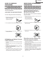
SAFETY NOTICE
AVIS POUR LA SECURITE
Many electrical and mechanical parts in DLP Projector
have special safety-related characteristics.
These characteristics are often not evident from visual
inspection, nor can protection afforded by them be
necessarily increased by using replacement components
rated for higher voltage, wattage, etc.
Replacement parts which have these special safety
characteristics are identified in this manual; electrical
components having such features are identified by “å”
and shaded areas in the Replacement Parts Lists and
Schematic Diagrams. For continued protection,
replacement parts must be identical to those used in the
original circuit. The use of a substitute replacement parts
which do not have the same safety characteristics as
the factory recommended replacement parts shown in
this service manual, may create shock, fire or other
hazards.
De nombreuses pièces, électriques et mécaniques, dans
les projecteur à DLP présentent des caractéristiques
spéciales relatives à la sécurité, qui ne sont souvent
pas évidentes à vue.
Le degré de protection ne peut pas être nécessairement
augmentée en utilisant des pièces de remplacement
étalonnées pour haute tension, puissance, etc.
Les pièces de remplacement qui présentent ces
caractéristiques sont identifiées dans ce manuel;
les pièces électriques qui présentent ces particularités
sont identifiées par la marque “å” et hachurées dans la
liste des pièces de remplacement et les diagrammes
schématiques. Pour assurer la protection, ces pièces
doivent être identiques à celles utilisées dans le circuit
d’origine. L’utilisation de pièces qui n’ont pas les mêmes
caractéristiques que les pièces recommandées par
l’usine, indiquées dans ce manuel, peut provoquer des
électrocutions, incendies ou autres accidents.
WARNING: The bimetallic component has the primary
conductive side exposed. Be very careful in
handling this component when the power is on.
AVERTISSEMENT: La composante bimétallique dispose du
conducteur primaire dénudé. Faire
attention lors de la manipulation de cette
composante sous tension.
12345678901234567890123456789012123456789012345678901234567890121234567890123456789012345678901212
12345678901234567890123456789012123456789012345678901234567890121234567890123456789012345678901212
12345678901234567890123456789012123456789012345678901234567890121234567890123456789012345678901212
4
XV-Z9000U/E
NOTE TO SERVICE
PERSONNEL
12345678901234567890123456789012123456789012345
12345678901234567890123456789012123456789012345
NOTE POUR LE PERSONNEL
D’ENTRETIEN
12345678901234567890123456789012123456789012345
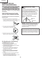
UV-RADIATION PRECAUTION
12345678901234567890123456789012123456789012345
12345678901234567890123456789012123456789012345
PRECAUTION POUR LES RADIATIONS UV
12345678901234567890123456789012123456789012345
12345678901234567890123456789012123456789012345
The light source, lamp, in the projector emits small
amounts of UV-Radiation.
La source de lumière, la lampe , dans le projecteur
émet de petites quantités de radiation UV.
AVOID DIRECT EYE AND SKIN EXPOSURE.
EVITEZ TOUTE EXPOSITION DIRECTE
DES YEUX ET DE LA PEAU.
To ensure safety please adhere to the following:
Pour votre sécurité, nous vous prions de respecter
les points suivants:
12345678901234567890123456789012123456789012345
1. Toujours porter des lunettes de soleil lors d’un
entretien du projecteur
avec la lampe allumée
et le haut du coffret retiré.
1. Be sure to wear sun-glasses when servicing the
projector with the lamp
turned “on” and the top
enclosure removed.
2. Ne pas faire fonctionner la lampe à l’extérieur du
boîtier de lampe.
2. Do not operate the lamp outside of the lamp housing.
3. Ne pas faire fonctionner plus de 2 heures avec le
coffret retiré.
3. Do not operate for more than 2 hours with the
enclosure removed.
Précautions pour les radiations UV
et la lampe moyenne pression
UV-Radiation and Medium Pressure
Lamp Precautions
1. Toujours débrancher la fiche AC lors du
remplacement de la lampe.
2. Laisser l’unité refroidir pendant une heure avant de
procéder à l’entretien.
3. Ne remplacer qu’avec une lampe du même type.
Type BQC-XVZ9000/1, caractéristique 355V/250W.
4. La lampe émet de petites quantités de radiation UVéviter tout contact direct avec les yeux.
5. La lampe moyenne pression implique un risque
d’explosion. Toujours suivre les instructions
d’installation décrites ci-dessous et manipuler la
lampe avec soin.
1. Be sure to disconnect the AC plug when replacing
the lamp.
2. Allow one hour for the unit to cool down before
servicing.
3. Replace only with same type lamp. Type BQCXVZ9000/1 rated 355V/250W.
4. The lamp emits small amounts of UV-Radiation, avoid
direct-eye contact.
5. The medium pressure lamp involves a risk of
explosion. Be sure to follow installation instructions
described below and handle the lamp with care.
5
XV-Z9000U/E
12345678901234567890123456789012123456789012345
12345678901234567890123456789012123456789012345
12345678901234567890123456789012123456789012345
12345678901234567890123456789012123456789012345
12345678901234567890123456789012123456789012345
12345678901234567890123456789012123456789012345
UV-RADIATION PRECAUTION (Continued)
1234567890123456789012345678901212345678901234
1234567890123456789012345678901212345678901234
1234567890123456789012345678901212345678901234
PRECAUTION POUR LES RADIATIONS UV (Suite)
12345678901234567890123456789012123456789012345
12345678901234567890123456789012123456789012345
12345678901234567890123456789012123456789012345
Lamp Replacement
Remplacement de la lampe
Note:
Remarque:
Since the lamp reaches a very high temperature
during units operation replacement of the lamp
should be done at least one hour after the power
has been turned off. (to allow the lamp to cool off.)
Installing the new lamp, make sure not to touch the
lamp (bulb) replace the lamp by holding its reflector
2.
[Use original replacement only.]
Comme la lampe devient très chaude pendant le
fonctionnement de l’unité, son remplacement ne doit
être effectué au moins une heure après avoir coupé
l’alimentation (pour permettre à la lampe de refroidir).
En installant la nouvelle lampe, s’assurer de ne pas
toucher la lampe (ampoule). Remplacer la lampe en
tenant son réflecteur 2.
[N’utiliser qu’un remplacement d’origine.]
1 Lampe
1 Lamp
2 Reflecteur
2 Reflector
DANGER ! –– Never turn the power on without the
lamp to avoid electric-shock or damage of the
devices since the stabilizer generates high voltages
at its start.
DANGER ! –– Ne jamais mettre sous tension sans
la lampe pour éviter un choc électrique ou des
dommages des appareils car le stabilisateur génère
de hautes tensions à sa mise en route.
Since small amounts of UV-radiation are emitted from
an opening between the exhaust fans, it is recommended to place the cap of the optional lens on the
opening during servicing to avoid eye and skin exposure.
Comme de petites quantités de radiation UV sont
émises par une ouverture entre les ventilateurs aspirants, il est recommandé de placer le capuchon
de l’optique optionnelle sur l’ouverture pendant
l’entretien pour éviter une exposition des yeux et la
peau.
6
XV-Z9000U/E
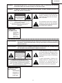
WARNING:
High brightness light source, do not stare into the beam of light, or view directly. Be especially
careful that children do not stare directly in to the beam of light.
WARNING:
TO REDUCE THE RISK OF FIRE OR ELECTRIC SHOCK, DO NOT EXPOSE THIS UNIT TO
MOISTURE OR WET LOCATIONS.
CAUTION
The lighting flash with arrowhead within a
triangle is intended to tell the user that
parts inside the product are risk of electric
shock to persons.
RISK OF ELECTRIC SHOCK.
DO NOT REMOVE SCREWS
EXCEPT SPECIFIED USER
SERVICE SCREW
CAUTION: TO REDUCE THE RISK OF ELECTRIC SHOCK,
DO NOT REMOVE CABINET.
NO USER-SERVICEABLE PARTS EXCEPT LAMP UNIT.
REFER SERVICING TO QUALIFIED SERVICE
PERSONNEL.
The exclamation point within a triangle is
intended to tell the user that important
operating and servicing instructions are in
the manual with the projector.
CAUTION
(POWER Unit)
For continued
protection against
risk of fire,
replace only with
same type and
rating of fuse.
(F7001, F7002)
12345678901234567890123456789012123456789012345678901234567890121234567890123456789012345678901212
12345678901234567890123456789012123456789012345678901234567890121234567890123456789012345678901212
AVERTISSEMENT: Source lumineuse de grande intensité. Ne pas fixer le faisceau lumineux ou le regarder
directement. Veiller particulièrement à éviter que les enfants ne fixent directement le
faisceau lumineux.
AVERTISSEMENT: AFIN D’EVITER TOUT RISQUE D’INCENDIE OU D’ELECTROCUTION, NE PAS PLACER
CET APPAREIL DANS UN ENDROIT HUMIDE OU MOUILLE.
ATTENTION
L’éclair terminé d’une flèche à l’intérieur
d’un triangle indique à l’utilisateur que les
pi‘eces se trouvant dans l’appareil sont
susceptibles de provoquer une décharge
électrique.
RISQUE
D’ELECTROCUTION NE
PASRETIRER LES VIS, A
L’EXCEPTION DES VIS DE
REPARATION UTILISATEUR
SPECIFIEES
Le point d’exclamation à l’intérieur d’un
triangle indique à l’utilisateur que les
instructions de fonctionnement et
d’entretien sont détaillées dans les
documents fournis avec le projecteur.
ATTENTION: POUR EVITER TOUT RISQUE
D’ELECTROCUTION, NE PAS RETIRER LE CAPOT.
AUCUNE DES PIECES INTERIEURES N’EST REPARABLE
PAR L’UTILISATEUR, A L’EXCEPTION DE L’UNITE DE
LAMPE. POUR TOUTE REPARATION, S’ADRESSER A UN
TECHNICIEN D’ENTRETIEN QUALIFIE.
PRECAUTION
(Unite d’admission)
Pour une protection
continue contre les
risques d’incendie,
ne remplacer
qu’avec un fusible
du même type.
(F7001, F7002)
7
XV-Z9000U/E
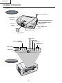
Location of Controls
Projector
Front and Top View
Remote control sensor
Lens shift dial
Zoom knob
TEMPERATURE WARNING indicator
LAMP REPLACEMENT indicator
Focus ring
POWER indicator
Adjuster
Intake ventilative hole
Adjuster
Remote control sensor
Lens cap
MENU button
RESIZE button
ADJUSTMENT buttons
('/"/\/|)
INPUT button
POWER buttons
(ON/OFF)
ENTER button
UNDO button
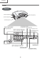
Side and Rear View
8
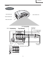
XV-Z9000U/E
Projector
Side and Rear Vie
Intake ventilative hole
Intake ventilative hole 4
Exhaust ventilative hole
Remote control sensor
w
S-VIDEO
INPUT 3 terminal
(4-pin Mini DIN)
INPUT 5 COMPUTER-RGB port
(15-pin Mini D-sub)
INPUT 1 COMPONENT/
RGB terminals (RCA)
RS-232C port
(9-pin D-sub)
DC 12 V OUTPUT terminal
(200 mA MAX.)
XV-Z9000U
INPUT 2 COMPONENT/
AC socket
RGB terminals (RCA)
XV-Z9000E
VIDEO INPUT 4 terminal (RCA)
9
Wired remote
control jack
XV-Z9000U/E
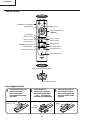
Remote Control
Front View
POWER buttons (ON/OFF)
MENU button
ENTER button
ADJUSTMENT buttons
(\/|/'/")
UNDO button
INPUT 1 button
INPUT 3 button
INPUT 2 button
INPUT 4 button
INPUT 5 button
THEATER MODE button
RESIZE button
CLR TEMP buttons
GAMMA button
KEYSTONE button
AUTO SYNC button
BACKLIGHT button
Top View
Remote control signal transmitter
Wired remote control jack
Insertingthe batteries
1
Pull down the tab on the
batterycover and
remove the cover
towardsthe directionof
the arrow.
2
Insert two AA size
batteries,makingsure
the polaritiesmatch the
+ and – marks inside
the batterycompartment.
3
Insert the lower tab of
the batterycover into
the opening,and press
the cover untilit clicks
in place.
Battery
Battery cover
Battery
compartment
10
XV-Z9000U/E
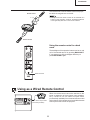
The remote control can be used to contr ol the projector within the range shown on the left.
Remote Control
23 (7 m)
45˚
• The signal from the remote control can be reflected off a
screen for easy operation. However, the effective distance
of the signal may differ due to the scr een material.
30˚
30˚
45˚
30˚
Remote Control
Using the remote control in a dark
room
The backlights of the operation buttons can be tur ned
on for five seconds and of f by pressing BACKLIGHT.
If you want to turn off the backlights while they ar
press BACKLIGHT again.
BACKLIGHT button
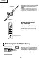
Using as a Wired Remote Control
When the remote control cannot be used due to the
range or positioning of the pr ojector (rear projection,
etc.), connect a 3.5 mm stereo minijack cable
(commercially available) fr om the wired remote control
jack on the top of the remote control to the Wired remote
control jack on the back of the projector .
3.5 mm stereo minijack cable
(commercially available)
11
XV-Z9000U/E
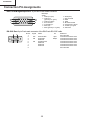
Connection Pin Assignments
INPUT 5 RGB Signal Input Port: 15-pin Mini D-sub female connector
RGB Input
15
10
5
11
6
1
Analog
1. Video input (red)
2. Video input
(green/sync on green)
3. Video input (blue)
4. Not connected
5. Composite sync
6. Earth (red)
7. Earth (green/sync on green)
8.
9.
10.
11.
12.
13.
14.
15.
Earth (blue)
Not connected
GND
GND
Bi-directional data
Horizontal sync signal
Vertical sync signal
Data clock
RS-232C Port: 9-pin D-sub male connector of the DIN-D-sub RS-232C cable
3
5
6
1
Pin No.
1
2
3
4
5
6
7
8
9
Signal
RD
SD
SG
Name
Receive Data
Send Data
Reserved
Signal Ground
Reserved
Reserved
Reserved
12
I/O
Input
Output
Reference
Not connected
Connected to internal circuit
Connected to internal circuit
Connected to internal circuit
Connected to internal circuit
Connected to internal circuit
Connected to internal circuit
Connected to internal circuit
Not connected
XV-Z9000U/E
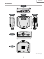
Dimensions
Rear View
Top View
Side View
7 (178)
15 49/50 (406)
Side View
Front View
18 11/16 (475)
Bottom View
Unit: inches (mm)
13
XV-Z9000U/E
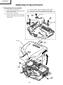
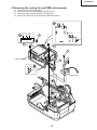
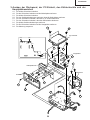
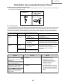
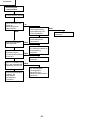
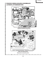
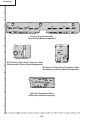
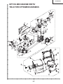
REMOVING OF MAJOR PARTS
1. Removing the top panels
1-1. Remove the six lock screw.
1-2. Press on side Arrow A of the bottom body
and Lift the rear body.
1-3. Disconnect the connector.
1-4. Press on front Arrow B of the bottom
body and unhook the claws, and detach
the top body.
2-1. Remove the two screws and detach the LED PWB.
2-2. Remove the one screw and detach the R/C PWB.
2-3. Remove the three screws and detach the operation PWB.
2-1
R/C PWB
2-2
2-3
LED PWB
Operation PWB
Top body
1-1
1-3
1-4
1-1
1-4
1-1
1-4
B
1-2
A
1-4
B
14
1-1
XV-Z9000U/E
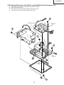
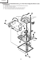
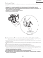
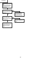
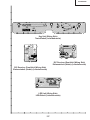
2. Removing the cooling fan and PWB unit assembly.
3-1.
3-2.
3-3.
3-4.
Disconnect the eleven connectors.
Remove the two screws and detach the lamp socket.
Remove the two screws and detach the cooling fan.
Remove the four screws and detach the PWB unit assembly.
3-1
3-1
(J5)
(RC)(TA)
(J2)
(FD) (FB)
(J3) (DB1)
3-4
(FA)
3-4
3-4
3-3
PWB unit assembly
3-2
LAMP
3-1
Door SW
Bi-Metal
Cooling Fan
15
XV-Z9000U/E
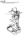
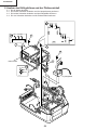
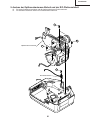
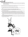
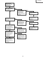
3. Removing the rear panel, PC unit, cooling duct and main PWB unit.
4-1.
4-2.
5-1.
5-2.
6-1.
7-1.
8-1.
8-2.
8-3.
Remove the two screws.
Remove the three screws and detach the rear panel.
Remove the two screws.
Remove the four hexagonal supports and detach the shield plate.
Remove the four screws and detach the PC I/F unit.
Remove the four screws and detach the cooling duct.
Remove the two hexagonal supports.
Remove the five screws and detach the main PWB unit.
Remove the lock of the holder.
6-1
6-1
PC I/F unit
(TB)
(EA)
(FC)
8-2
8-1
Main PWB unit
(EB)
(CA)
8-2
7-1
Shield plate
Cooling duct
5-2
Rear panel
5-1
5-2
4-1
4-2
8-3
7-1
16
XV-Z9000U/E
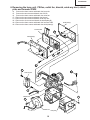
4. Removing the power unit shield , power/ballast unit and power unit.
9.
Remove the seven screws and detach the power unit shield.
10-1. Remove the two screws.
10-2. Remove the four white supports and detach the power unit.
11. Remove the four screws and detach the power unit.
10-1
Power unit shield
Ballast unit
9
11
11
Power unit
10-2
10-2
9
17
XV-Z9000U/E
5. Removing the optical mechanism unit and R/C PWB unit.
12.
13.
Remove the six screws and detach the optical mechanism unit.
Remove the one screw and detach the R/C PWB unit.
12
12
Optical mechanism unit
12
13
R/C PWB unit
18
XV-Z9000U/E
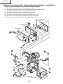
6. Removing the lamp unit, CW fan, outlet fan, bimetal, wind way duct, shield
plate and formater PWB.
14. Remove the three screws and detach the lamp unit.
15. Remove the two screws and detach the CW fan.
16. Remove the three screws and detach the outlet fan.
17-1. Remove the two screws and detach the bimetal.
17-2. Remove the two screws and detach wind way duct.
18-1. Remove the six screws and detach the shield plate(B).
18-2. Remove the three screws and detach the formater PWB.
18-3. Remove the three screws and detach the shield plate(A).
Shield Plate(A)
Formater PWB
18-3
Shield Plate(B)
18-2
18-2
18-1
17-2
15
Wind way Duct
17-1
Bimetal
14
16
Outlet Fan
Lamp unit
19
XV-Z9000U/E
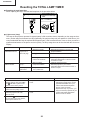
Resetting the TOTAL LAMP TIMER
● Resetting the total lamp timer
When replacing the lamp, reset the total lamp timer in the procedure below.
1
Plug in the power cord.
POWER ON on
2 Press
projector to reset lamp
timer.
While holding down ENTER, [
and >, press POWER ON.
● Light source (lamp)
The lamp in this projector operates for approximately 2,000 cumulative hours, depending on the usage environment. (As the usage environment can vary significantly, the projector lamp may not operate for 2,000 hours.) It is
recommended that the lamp be replaced after approximately 1,900 cumulative hours of use or when you notice a
significant deterioration of the picture and color quality. The lamp usage time can be checked with the On-screen
Display.
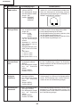
Maintenance Indicator
TEMPERATURE
WARNING indicator
LAMP REPLACEMENT indicator
Condition
Possible Solution
Problem
• Blocked air intake.
• Relocate the projector to an area with
proper ventilation.
• Clogged air filter .
• Clean the filters.
• Cooling fan breakdown.
• Internal circuit failure.
• Take the projector to your nearest
Authorized SharpVision or Service Center
or Dealer for repair.
The lamp does not
light up.
• Burnt-out lamp.
• Lamp circuit failure.
The lamp requires
replacement.
• Lamp has been used for
over 1,900 hours.
• Carefully replace the lamp.
• Take the projector to your nearest
Authorized Sharp Vision Service Center or
Dealer for repair.
The internal
temperature is
abnormally high.
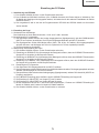
Condition
The LAMP REPLACEMENT
indicator lights up red, and “LAMP”
and “ ” will flash in yellow in the
lower-left corner of the picture.
Problem
• Lamp has been used for over 1,900
hours.
A significant deterioration of the
picture and color quality occurs.
The power will automatically turn
off and the projector will enter
stand-by mode.
“LAMP” and “ ” will flash in red in
the lower-left corner of the picture,
and the power will turn off.
• Lamp has been used for over 2,000
hours.
20
Possible Solution
• Purchase a replacement lamp unit
(lamp/cage module) of the current
type BQC-XVZ9000/1 from your
nearest Authorized SharpVision
Service Center or Dealer.
• Replace the lamp. If you wish, you
may have the lamp replaced at your
nearest Authorized SharpVision
Service Center or Dealer.
XV-Z9000U/E
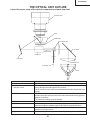
THE OPTICAL UNIT OUTLINE
Layout for proper setup of the optical components and parts (top view)
Projection lens
Prism
DMD Chips
Condensor lens
IR-cut mirror
Light tunnel
Relay lens
Fold mirror
Condensor lens
Color filter
Lamp
Item
1 Lamp
2 Condebsor lens, IR-cut mirror
and light- tunnel
3 Color filter
4 Relay lens and fold mirror
5 Prism
6 DMD chip
7 Projection lens
Descriptions
The DC Light source lamp with parabola reflector.
The condensor lens leads the light generated from the lamp to the end surface of the light-tunnel through the IR-cut mirror.
The IR-cut mirror is set in this unit to eliminate the excessive heat by the lamp
energy.
This color filter separates the white light into the 3 colors R,G and B.
A photo-sensor should be set in this unit to detect the transition timing pproperly
between color filters.
The maximum rrotating speed is 9000rpm.
This unit leads the illumination spot to effective area on DMD.
This prism also leads the illumination spot to effective area on DMD and at the
same time leads the reflection lights on the DMD to the projection lens.
This chip turns on and off in projection to each color component per dot depending on the input source.
This lens enlarges and projects the incidend light coming from the DMD.
21
XV-Z9000U/E
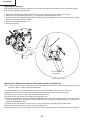
Adjusting the mirrors
Make adjustment by the indication territory on the screen to prevent the circumference of the screen from getting
dark because a lighting range deviated.
1. Remove the top body so that the optical unit may be seen. Display white only screen on the screen.
2. Detach the mirror adjustment part cover 1 on the bottom right of the projection lens.
3. Turn three screws with special hexagon wrench (9HPH10XL120) and adjust so that a part of the screen may not get
dark because a lighting range deviated.
4. Mount the adjustment part cover 1.
5. Mount the top panel.
Insert hexagon wrench
in this direction.
Expansion figure of part A
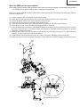
Adjusting the back focal distance after replacing the projection lens
Note: A piece of temporary tape is attached on the focus ring that comes with the replacement projection lens. Keep
this tape in place until the finish of the adjustment.
(1) Provide a distance of 2.4 m between the set and the screen and adjust the zoom knob to “wide end”.
(2) Adjust the lens shift until the projection lens comes to the same level as the center of the screen.
(3) Detach the optical unit top cover A from behind the projection lens.
(4) Loosen the four hex screws B in the back of the projection lens.
(5) Insert the adjustment screwdriver C (9EVDRIVERZ9000) in the hole D at the back of the lens. Put the center of the
screen in the best focus. (Preferably feed the SXGA signal for 1-dot white crosshatch pattern or 1-dot white dot
pattern on black background.)
(6) Tighten the four hex screws B to the torque of 0.3 Nm (3.06 kgfcm), and apply screw loctite to them.
(7) Peel the temporary tape off the focus ring of the projection lens.
(8) Attach the optical unit top cover A back into position. Finally fix the two screws E and apply screw loctite to them.
22
XV-Z9000U/E
When the DMD unit has been replaced
Note: DMD chip and Formatter PWB are supplied at the same time, and an exchange only with DMD isn't done.Refer
to "REMOVING OF MAJOR PARTS" when exchanging Formatter PWB.
There is no need to readjust the back focal distance of the projection lens. If focusing is noticeably poor, however,
make this readjustment.
(1)
(2)
(3)
(4)
(5)
(6)
(7)
Provide a distance of 2.4 m between the set and the screen.
Adjust the lens shift until the projection lens comes to the same level as the center of the screen.
Detach the optical unit top cover A from behind the projection lens.
Loosen the four hex screws B in the back of the projection lens.
Adjust the zoom knob at the front of the projection lens to “tele end” and ensure good focusing.
Then adjust the zoom knob at the front of the projection lens to “wide end”.
Insert the adjustment screwdriver C (9EVDRIVERZ9000) in the hole D at the back of the lens. Put the center of
the screen in the best focus. (Preferably feed the SXGA signal for 1-dot white crosshatch pattern or 1-dot white
dot pattern on black background.)
(8) Move the zoom knob from “wide end” back to “tele end” and see if focusing is ensured. If not, repeat the above
steps (5), (6) and (7) until the best focus is achieved.
(9) Tighten the four hex screws B to the torque of 0.3 Nm (3.06 kgfcm), and apply screw loctite to them.
(10) Attach the optical unit top cover A back into position. Finally fix the two screws E and apply screw loctite to them.
E
E
A
C
X
B
B
D
B
B
Expansion figure of part X
23
XV-Z9000U/E
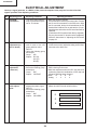
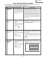
ELECTRICAL ADJUSTMENT
Hook up a signal generator, or a DOSV or Mac personal computer to the projector in order to feed the
signals specified in the Adjusting conditions.
No.
Adjusting point
Adjusting conditions
Adjusting procedure
1
EEPROM
initialization
1. Turn on the power (with the
lamp on) and warm up the
set for 15 minutes.
1. Make the following settings.
Press SW2002 to enter the process mode. Execute
the S2 and S4 commands on the SSS menu. With
the S2 command, all the circuit boards than the PC
board will be initialized. Do not activate the S1 command because otherwise the PC board itself will be
initialized.
(The delivered PC board has been factory-adjusted.)
If by any chance the PC board must be readjusted,
follow the instructions in "Adjusting the PC Board"
on page 28.
2
RGB drive
adjustment (on
the PC board)
1. Feed the 100% and 0% signals for each of the red,
green and blue colors.
INPUT5
2. Select the following group
and subject.
Group: A/D
Subject: R-D (R)
G-D (G)
B-D (B)
1. Using the control switches on the set or the buttons
on the remote control, adjust the setting until bit dropouts start at the white level.
3
DLP voltage
adjustment
(reference)
1. Keep out any signal input.
2. Select the following group
and subject.
Group: DLP
Subject: VOLTAGE
1. Select the setting of the rank marked on the formatter
PWB, referring to the menu.
2. Make this adjustment when the DLP chip has been
replaced or when the combination of DLP chip and
formatter PWB has been changed.
3. Rank
B
C
D
E
Setting 1
2
3
4
4
Color wheel
index adjustment
1. Feed the color wheel index
adjustment pattern signal.
INPUT5
2. Select the following group
and subject.
Group: DLP
Subject: CW INDEX
1. Adjust the setting so that the R, G and B lamp tone
pattern should be smooth without noises.
R
G
B
24
XV-Z9000U/E
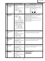
No.
Adjusting point
Adjusting conditions
Adjusting procedure
5
RGB tone
reproduction
adjustment
1. Feed the SMPTE pattern
signal.
INPUT5
2. Select the following group
and subject.
Group: DLP
Subject: R-BRIGHT
G-BRIGHT
B-BRIGHT
1. Make sure the 100% and 95% white and the 0%
and 5% black tones are visible.
2. If the black tone appears otherwise, finely adjust the
R-BRIGHT, G-BRIGHT and B-BRIGHT settings.
6
Adjusting the
Background
Color
1. Select the following group
and subject.
Group: DLP
Subject: R-GAIN
G-GAIN
B-GAIN
2. Feed the Component
video, 75% white signal.
3. Signal level: 0.7±0.05 Vp-p
(sync section not included)
4. R-GAIN, G-GAIN and BGAIN initial settings: 95
5. Target chromaticity:
x = 0.272 ± 0.005
y = 0.310 ± 0.005
(color temperature 9500K+15 µV)
1. Project an image over a 40-inch screen and
measure the chromaticity at the center using a
chromaticity meter.
2. Keep the G-GAIN setting fixed at 95.
3. Adjust the B-GAIN setting to get the y value to its
target chromaticity.
4. Adjust the R-GAIN setting to get the x value to its
target chromaticity.
7
Video horizontal
center adjustment
1. Feed the NTSC monoscope pattern signal.
INPUT4
2. Select the following group
and subject.
Group: VIDEO 1
Subject: NTSC-H
1. Using the control switches on the set or the buttons
on the remote control, adjust the setting until the
overscan should be equal at right and left.
8
Video BRIGHTNESS adjustment
1. Feed the NTSC 10-step
gray-scale signal.
2. Select the following group
and subject.
Group: VIDEO1
Subject: BRIGHT
1. Using the control switches on the set or the buttons
on the remote control, adjust the setting until more
bit dropouts start at the 0% black level.
9
Video picture
adjustment
1. Feed the NTSC 10-step
gray-scale signal.
2. Select the following group
and subject.
Group: VIDEO1
Subject: PICTURE
1. Using the control switches on the set or the buttons
on the remote control, adjust the setting until bit dropouts start at the 100% white level.
10
Video tint
adjustment
1. Feed the internal 8CH (split
color bar) signal.
INPUT4
2. Select the following group
and subject.
Group: VIDEO1
Subject: TINT
1. Check the fixed setting.
Fixed setting: 128
25
XV-Z9000U/E
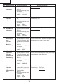
No.
Adjusting point
Adjusting conditions
Adjusting procedure
11
NTSC color
saturation
adjustment
1. Feed the internal 8CH (split
color bar) signal.
INPUT4
2. Select the following group
and subject.
Group: VIDEO1
Subject: N-COLOR
1. Check the fixed setting.
Fixed setting: 105
12
PAL color
saturation
adjustment
1. Feed the PAL color bar signal.
INPUT4
2. Select the following group
and subject.
Group: VIDEO1
Subject: P-COLOR
1. Check the fixed setting.
Fixed setting: 110
13
SECAM color
saturation
adjustment
1. Feed the SECAM color bar
signal.
INPUT4
2. Select the following group
and subject.
Group: VIDEO1
Subject: S-COLOR
1. Check the fixed setting.
Fixed setting: 110
14
DTV BRIGHTNESS adjustment
(Take this
procedure for
Model XVZ9000U only.)
1. Feed the 100% color bar
signal (component signal)
or the 10-step gray scale
signal to the input terminal
480I.
INPUT2
2. Select the following group
and subject.
Group: DVD
Subject: BRIGHT
1. Using the control switches on the set or the buttons
on the remote control, adjust the setting until more
bit dropouts start at the 0% black level.
15
DTV CONTRAST
adjustment
(Take this
procedure for
Model XVZ9000U only.)
1. Feed the 100% color bar
signal (component signal)
or the 10-step gray scale
signal to the input terminal
480I.
INPUT2
2. Select the following group
and subject.
Group: DVD
Subject: CONTRAST
1. Using the control switches on the set or the buttons
on the remote control, adjust the setting until bit dropouts start at the 100% white level.
16
DVD color
saturation
adjustment
DVD tint adjustment
1. Feed the 100% color bar
signal (480I component
signal) to the Y, Pb and Pr
input terminals.
INPUT2
2. Select the following group
and subject.
Group: DVD
Subject: COLOR
TINT
1. Check the fixed settings.
Fixed setting: TINT at 32
COLOR at 36
26
XV-Z9000U/E
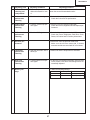
No.
Adjusting point
Adjusting conditions
Adjusting procedure
17
White balance
checking and
readjustment
1. Take the adjustment conditions discussed for Item
11.
Make sure there is no white balance difference between the set and the standard monitor.
18
Color-related
performance
checking
1. Feed the color bar signal.
1. Select L1 from the process mode LINE.
Check the Color and Tint performance.
19
Video-related
performance
checking
1. Feed the monoscope pattern signal.
1. Select L2 from the process mode LINE.
Check the Picture, Brightness and Sharpness performance.
20
RGB-related
performance
checking
1. Feed the RGB signal.
1. Select L4 from the process mode LINE.
Check the Picture, Brightness, Red, Blue, Clock,
Phase, H-Position and V-Position performance.
21
Off-timer performance
22
Thermistor
performance
checking
1. Heat the thermistor with a
hair dryer.
1. Make sure that the temperature is indicated.
23
Auto sync
performance
checking
1. Feed the phase check pattern signal.
1. In the VGA, SVG Aand XGAmodes, make sure the
Clock, Phase, H-Pos and V-Pos settings can be automatically adjusted.
24
Delivery settings
1. Select OFF from the process mode LINE.
Make sure the off-timer starts with 5 minutes
onscreen and the set turns itself off in 5 minutes.
1. Make the following settings.
Destination
27
Adjustment process Remote control setting
XV-Z9000U
S4
Factory setting 4
XV-Z9000E
S3
Factory setting 3
XV-Z9000U/E
Adjusting the PC Board
1. Initializing the EEPROM
1) Press SW2002 to enter the process mode.
2) Execute the S1 command on the SSS menu. (The S1 command initializes the PC board alone. Do not
execute the S2 command because otherwise the adjustment data other than the PC board will be initialized.)
3) Make sure that the program version VER.XXX on the SPECIAL menu is the latest one.
2. Adjusting the levels
2.1 Setting the oscilloscope
Set the oscilloscope range to DC 1V/div. and 5 µsec/div.
2.2 Connecting the PC interface
1) Connect the specified cable between the analog output jack (signal generator) and the DUSB connector
(INPUT5 of the projector). Set the projector’s input selector to INPUT5.
2) Set the signal generator to the XGA mode (1024x768, 60 Hz, 32 tones). Adjust the output amplitude to 700
mVp-p between the black and white levels (terminated with a 75-ohm impedance).
3) Turn on the power.
2.3 Adjusting and checking the levels
1) Press SW2002 to enter the process mode.
2) Adjust the R-BRIGHT setting of Group A/D until bit dropouts start at the black level of the red signal.
3) Adjust the B-BRIGHT setting of Group A/D until bit dropouts start at the black level of the blue signal.
4) Adjust the G-BRIGHT setting of Group A/D until bit dropouts start at the black level of the green signal.
2.4 Adjusting the DTV
1) Feed the signal to the INPUT2’s RCA input terminal.
2) Set the signal generator to the 1080i 60-Hz mode with white signal. Adjust the output amplitude to 700 mVpp between the black and white levels.
3) Connect the specified cable between the analog output (signal generator) and the RCA connector (INPUT2
of the projector).
4) Make the G-BRIGHT setting the same as the G-BRIGHT setting of Group A/D.
5) Adjust the CB-OFFSET setting of Group DTV to 20.
6) Adjust the CR-OFFSET setting of Group DTV to 20.
7) When the CB-OFFSET and CR-OFFSET settings have been made, add 5 points to the G-BRIGHT setting for
Model XV-Z9000U and 4 points for Model XV-Z9000E.
8) Finally press SW2002 to exit from the process mode.
28
XV-Z9000U/E
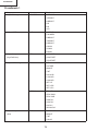
Process menu 1
Group
Sub Group
Subject
Adjust PC Image
A/D
R-BRIGHT
G-BRIGHT
B-BRIGHT
R-D
B-D
G-D
Adjust HDDE formatter
DLP
VOLTAGE
CW-INDEX
R-BRIGHT
G-BRIGHT
B-BRIGHT
R-GAIN
G-GAIN
B-GAIN
Adjust Component
DTV
(High Definition)
G-BRIGHT
CB-OFFSET
CR-OFFSET
Adjust VIDEO Image
VIDEO1
NTSC-H
PICTURE
BRIGHT
TINT
N-COLOR
P-COLOR
S-COLOR
SET UP
SET UP B
SET UP C
VIDEO2
PEAK FIL
PEAK GAIN
PEAK COR
N358 DLY
N433 DLY
PAL DLY
SECAM DLY
Adjust Component
(480i)
DVD
CONTRAST
BRIGHT
TINT
COLOR
29
XV-Z9000U/E
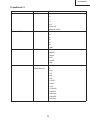
Process menu 2
Group
Sub Group
Subject
Process mode
LINE
L1
L2
L3
L4
OFF
TEMP OFF
SENSOR CHECK
INITIAL SETTING
SSS
TIME
S1
S2
S3
S4
S5
LAMP
Sample Pattern
PATTERN
RGB
RGB(50)
CROSS
STEP
COLOR
CHR
Adjust CVIC
CVIC
MODDE
-PROGRESSIVE
IP
FILM
PTG
MSW
LSW
C-LEVEL
C-LIMIT
C-LPF
C-THRESH
C-MISSTH
C-MOVIEA
C-MOVIEB
C-MOVIEC
30
XV-Z9000U/E
Process menu 3
Group
Sub Group
Subject
Adjust CVIC
CVIC
BBN-TBL0
-ENHANCE-VIDEO
BBN-TBL1
DFC-TBL0
DFC-DIR0
DFC-EDG0
DFCTBL1
DFC-DIR1
DFC-EDG1
CVIC
BBN-TBL0
-ENHANCE-HDTV
BBN-TBL1
DFC-TBL
DFC-DIR
DFC-EDG
CVIC
BBN-GAIN0
-ENHANCE-RGB
BBN-GAIN1
BBN-GAIN2
BBN-TBL
DFC-TBL
DFC-DIR
DFC-EDG
CVIC
CUBIC-RGB
-SCREEN
CUBIC-VIDEO
CVIC
XEGTH
-IDC
XLTH1-H
XLTH1-L
XLTH2-H
XLTH2-L
VEGTH
VLTH1-H
VLTH1-L
VLTH2-H
VLTH2-L
Version Check etc.
(High Definition)
Special
IPL
E2PROM
ADR RD/RW
31
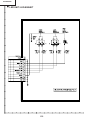
XV-Z9000U/E
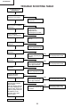
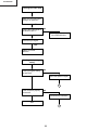
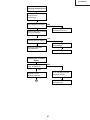
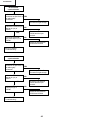
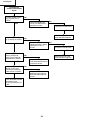
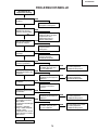
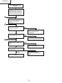
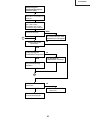
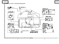
TROUBLE SHOOTING TABLE
Checking the basic
performance
Is the POWER LED on or
flickering in red or blue?
NO
Go to "Checking the
power unit"
YES
Is the set turned on by the
set's or remote controller's
power key?
NO
Go to "Checking the
microcomputer
peripherals" and
"Checking the PC PWB".
YES
Is the cooling fan
running? Is the lamp on?
NO
Go to "Checking the lamp
light-up".
YES
NO
Is the user menu
displayed?
Check the formatter
circuit’s peripheral circuits.
YES
Is the video input as
specified?
NO
YES
Is the component input as
specified?
Check the IC2505 circuit
and its peripheral circuits.
Are there output signals at
every other pin from pins
(41) to (60) of P3580?
NO
Check the IC2505 circuit
and its peripheral circuits.
Are there output signals at
every other pin from pins
(41) to (60) of P3580?
NO
Check the IC2505 circuit
and its peripheral circuits.
Are there output signals
at pins (32), (34) and (37)
of P3580?
NO
Check the IC2005 circuit
and its peripheral circuits.
NO
YES
Does the RS-232C
interface function?
NO
NO
YES
If the RGB input as
specified?
Are there output signals at
pins (32), (34) and (37) of
P3580?
Check the PC board
circuit’s peripheral circuits.
NO
YES
Recommended
NO
communication software:
“TERA TERM”
Make the following settings:
baud rate at 9600 bps, bit
length at 8 bits, stop bit at 1
bit and no parity. Press the
RETURN key on the
keyboard. Does “ERR”
show up again?
YES
END
32
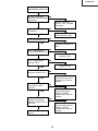
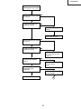
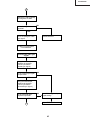
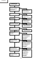
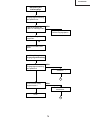
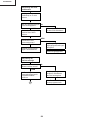
XV-Z9000U/E
Checking the power unit
Are all the connectors
NO
inside the power unit tightly
connected?
Insert the connectors
CN7105, 7103, 7101AND
7102 tightly.
YES
Is the lamp cover closed
completely?
NO
Tighten up the lamp door
closed with the screws.
YES
Is the bimetal switch off?
NO
Replace the bimetal switch
or press the red button to
reset.
YES
Is AC voltage applied
across the RL7001 relay?
NO
YES
Is AC voltage applied
across L7005?
Replace F7001.
NO
Replace F7002.
YES
Is there DC voltage of
about 6 V across C7151?
NO
Check the peripheral
circuits of Q7101~Q7107.
Replace any of them as
required.
YES
Is there DC voltage of
about 340 V across
CN7003?
NO
Check the circuits leading
to the primary side of
T7002 for damage.
Replace any of them as
required.
YES
Are there the specified
voltages at the output
terminals of CN7101 and
CN7102?
NO
Check the circuits leading
to the secondary side of
T7002 for damage.
Replace any of them as
required.
YES
Check the output PWB
circuits.
33
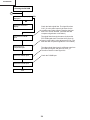
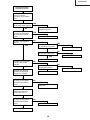
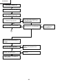
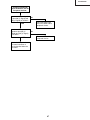
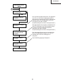
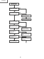
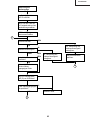
XV-Z9000U/E
Checking the PC PWB
0
Is the user menu properly
displayed?
YES
NO
Check the on-screen
display.
Check the DTV RGB
input.
Check the DTV
component input.
Check the VIDEO input.
Check the basic signal flow. The signal flow from
CVIC_IC to the panel output is the same for the
component and video signals. Therefore the lines
after CVIC are not checked. (The 480i and 580i
component signals are not included.)
The signal flows through the same circuits as the
DTV RGB signal does. Check the SOG (Sync On
Green) circuit and the color adjustment circuit. (The
480i and 580i component signals are not included.)
The video signal flows through a different route from
the RGB input signal, and goes into CVIC_IC.
Therefore check the video signal ICs.
Check the D-SUB input.
Check the D-SUB input.
End
34
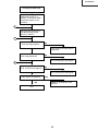
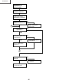
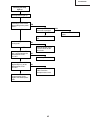
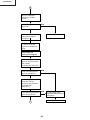
XV-Z9000U/E
Checking the RGB input
Feed the sync-separated DTV
RGB signal to INPUT1 or
INPUT2. (The 480i and 580i
component signals are not
included.)
1
Using the front-panel key or
the remote control, select
INPUT1 or INPUT2.
2
Does the image appear?
NO
Check to see if the video input is
as specified.
YES
Is the image disturbed?
NO
Go to "Checking the sync signal".
YES
3
Do R, G and B colors appear?
NO
Go to "Checking the RGB signal".
YES
Is the contour as specified?
NO
YES
IC8004 or its peripheral circuit
defective.
End
35
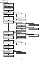
XV-Z9000U/E
Checking the video input
Make sure the input signal
setting is as specified.
YES
Is there the video signal at
the land of C8077?
NO
Input PWB defective.
YES
Check the sync signal.
YES
IC8025 or IC8004
defective.
Checking the input signal
setting
Is the input signal setting
as specified?
NO
Select the specified signal.
YES
2
Is the connector properly
connected?
NO
Reconnect the connector.
YES
End
1
36
XV-Z9000U/E
Checking the sync signal
Is there vertical sync signal
at TL8134?
NO
YES
Is there horizontal sync
signal at TL8133?
NO
Check the input signal
setting.
YES
Input PWB defective.
Is there vertical sync signal
at TL8131?
NO
YES
Is there horizontal sync
signal at TL8130?
NO
IC8302, IC8325, IC8299 or
their peripheral circuits
defective.
YES
Are both the vertical and
horizontal sync signals
timely?
NO
There is no problem with
the sync signal.
End.
YES
Is the signal generator
(input source) as
specified?
NO
Make the specified signal
source settings.
YES
Input PWB defective.
2
37
XV-Z9000U/E
Checking the RGB signal
Is the type of signal set at
RGB?
YES
NO
Set to the RGB signal.
Call the process mode.
Select R, G and B
separately on the pattern
menu.
Go to “Checking the GA4
peripheral circuits”.
Set the signal generator to
the gradation signal mode
in order to check the input
signal.
Measure the gradation
signals at TL8073, T8074,
T8075 and T8080.
Are there specified signals
at TL8073, TL8074,
TL8075 and TL8080?
YES
IC8025 or its peripheral
circuit defective.
NO
Are there input signals at
C8069 and C8061?
YES
IC8004 or its peripheral
circuit defective.
38
NO
Input PWB defective.
XV-Z9000U/E
Checking the GA4
peripheral circuits
Call the process mode, and
select R, G and B
separately on the pattern
menu.
Are there specified R, G
and B video output signals?
YES
End of checking the GA4
peripheral circuits.
NO
Are the measured signals
the same as the signals
selected on the pattern
menu?
NO
Is there clock signal at
R974?
YES
Output PWB defective.
NO
Is there clock signal
(37.125 MHz) at TL8114?
YES
YES
IC8029 defective.
NO
Is there clock signal
(37.125 MHz) at FL8110?
NO
X8005 defective.
YES
IC8025 defective.
Are there sync signals at
TL8026, TL8027 and
TL8028?
NO
Are there sync signals at
TL8112 and TL8133?
YES
YES
Using the oscilloscope,
measure the signals at
TL8141 thru TL8148.
Are the measured signals
the same as the signals
selected on the pattern
menu?
IC8029 defective.
NO
Digital panel PWB
defective.
YES
Using the oscilloscope,
measure the signals at
TL8106 thru TL8111.
Are the measured signals
the same as the signals
selected on the pattern
menu?
NO
IC8025 defective.
YES
IC8029 defective.
39
NO
IC8025 defective.
XV-Z9000U/E
Checking the
component inputs
(Except for 480I)
Feed the component signal
to INPUT1 or INPUT2.
Using the front panel key
or the remote control,
select INPUT1 or INPUT2.
Does an image appear on the NO
screen?
Go to "Checking the
SOG circuit".
YES
4
Are the colors as
specified?
YES
NO
Is the type of signal set at
COMPONENT?
YES
NO
Set the type of signal to
COMPONENT.
Carry out the process
adjustment.
NO
4
Is the image contour as
specified?
YES
IC8004 or IC8025
defective.
NO
End of checking the
component input.
40
XV-Z9000U/E
Checking the SOG circuit
Measure the signal at
TL8136 on the
oscilloscope.
Is the composite sync
signal played back timely?
YES
NO
There is no problem with
the SOG circuit. End.
Measure the land of C8069
on the oscilloscope.
Is there the Y signal
including the sync signal?
NO
Go to “Checking the input
signal settings”.
YES
SOG sync separation
circuit defective.
Input PWB defective.
Checking the on-screen
display.
Is the on-screen display
color as specified?
YES
NO
Carry out the output line
adjustment in the
adjustment process.
Go to “Checking the GA4
peripheral circuits”.
0
Get the flash ROM
reprogrammed.
41
XV-Z9000U/E
Checking the video input
Feed the composite video
signal to INPUT4.
Using the front panel key
or the remote control,
select INPUT4.
Select VIDEO as the type
of signal on the user menu.
5
Does the image appear?
NO
YES
Is the image disturbed?
NO
Go to "Checking the video
sync signal".
YES
NO
NO
Is the contour as specified?
Go to "Checking the video
sync signal".
Carry out the process
adjustment.
YES
There is no problem with
the video input. End.
5
Is there the video signal at
pin (72) of IC8338?
Is the video signal as
specified?
NO
YES
IC8338 defective.
6
42
XV-Z9000U/E
6
Measure the VPC (IC8338)
clock signal at TL8004.
Is the clock signal as
specified?
NO
YES
IC8338 defective.
Go to “Checking the video
sync signal”.
IC8025 or its peripheral
circuit defective.
Checking the video sync
signal
Using the oscilloscope,
measure the signal at
TL8140. (Check the
vertical sync signal.)
Is the vertical sync signal
as specified?
NO
YES
Using the oscilloscope,
measure the signal at
TL8142. (Check the
horizontal sync signal.)
Is the horizontal sync
signal as specified?
NO
Go to "Checking the input
signal setting".
YES
7
Input PWB defective.
43
XV-Z9000U/E
Checking the DSUB input.
Feed the PC-RGB signal to INPUT5.
Select INPUT5 as the input.
NO
Does the image appear?
Check to see if there are the R, G
and B signals at pins (126), (136)
and (146) of IC8004.
YES
Is there any distortion with the image?
YES
NO
Are there the R, G and B signals?
NO
YES
3
Check the vertical and horizontal sync
signals at pin (6) of IC8364 and pin (6)
of IC8385.
Are the sync signals as specified?
NO
Sync separation circuit, IC8354m
IC8365 or their peripheral circuit
defective.
NO
IC8302 or its peripheral circuit
defective.
YES
Are there the horizontal and vertical sync
signals at TL8130 and TL8131?
YES
IC8025, IC8004 or their peripheral
circuit defective.
44
DSUB connector
or its peripheral
part defective.
XV-Z9000U/E
Checking the lamp
light-up
The lamp fails to light up.
Is discharge sound heard
when turning on the power
switch?
YES
Is the lamp or CW line
socket out of position?
YES
NO
Replace the lamp or the
CW.
Are the cooling fans
running well?
NO
Check the power circuit
or the fan circuit on the
main circuit.
YES
Is a voltage of about DC
340 V applied across the
ballast power circuit
CP1001?
YES
Is a voltage of over 3.5 V
applied at pin (1) of the
ballast power circuit
CP1501?
YES
NO
Check the power circuit.
NO
Replace the ballast power
PWB. Check the
microprocessor circuit.
Check the
microprocessor circuit.
Replace the ballast power
PWB.
45
NO
Reconnect the sockets
tightly.
XV-Z9000U/E
No horizontal
synchronization
Is the terminal input
connection as specified? Is YES
the cable tightly
connected?
NO
Is there the horizontal sync
pulse at pin (14) of
IC2506?
NO
Check the line between
IC2506 and the input
terminal.
YES
Is there the horizontal
sync pulse at pin (11) of
IC2509?
Use the specified cable.
Reconnect it tight enough.
NO
Check the line between
IC2506 and IC2509.
YES
Go to "PC Board
Troubleshooting".
No vertical
synchronization
Is the terminal input
connection as specified? Is YES
the cable tightly
connected?
NO
Is there the vertical sync
pulse at pin (14) of
IC2501?
NO
Check the line between
IC2501 and the input
terminal.
YES
Is there the vertical sync
pulse at pin (8) of
IC2509?
YES
Use the specified cable.
Reconnect it tight enough.
NO
Check the line between
IC2506 and IC2509.
Go to "PC Board
Troubleshooting".
46
XV-Z9000U/E
Checking IC3504 (3D
Noise Reduction) and its
Peripheral Circuits
Are there the input signals
at pins (88) (Y signal) and
(96) (C signal) of IC3504?
NO
Check the signal input
circuit or IC2505 and its
peripheral circuits.
YES
Are there the output
signals at pins (84) (Y
signal) and (83) (C signal)
of IC3504?
YES
NO
Check IC3504 and its
peripheral circuits.
Check the line up to the
PC board connector or
the circuits that follow the
PC board.
47
XV-Z9000U/E
Checking the
Component and RGB
Inputs
Are there signals at pins
(34), (36) and (38) of
IC2505?
NO
Check the signal input
circuit or IC2505 and its
peripheral circuits.
YES
NO
There are no RGB colors.
YES
Are there signals at pins
(3), (5) and (6) of IC2507?
Check the circuit of the
color that fails to appear.
NO
Check the line between
Q2509 and Q2517 and its
peripheral circuits, or
IC2507.
YES
NO
There are no RGB colors.
YES
Are there signals at pins
(56/26), (58/28) and
(60/30) on the board-toboard section of P3580?
NO
Check the line between
Q2518 and Q2520 and its
peripheral circuits.
YES
Are there signals at pins
(49/19), (51/21) and
(53/23) on the board-toboard section of P3580?
YES
Check the circuit of the
color that fails to appear.
NO
Check the line from
Q2525 through Q2523 to
Q2524 and its peripheral
circuits.
Check the board-to-board
connections or the
circuits that follow the PC
board.
48
XV-Z9000U/E
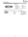
Technische Daten
Produkttyp Projector
Modell XV-Z9000E
Videosystem PAL/PAL 60/PAL-M/PAL-N/SECAM/NTSC 3.58/NTSC 4.43
DTV 480i/480P/720P/1080i
Display-Verfahren Single Panel Digital Micromirror Device (DMD™) von Texas Instruments, RGB optisches
Verschlussverfahren
DMD-Feld Feldformat: 0,8"
Antriebsverfahren: Digital Light Processing (DLP™) von Texas Instruments
Anzahl der Punkte: 921.600 Punkte (1.280 [H] × 720 [V])
Linse 1 –1,35 Zoom-Linse, F3,0,f=32,5 –44,0 mm
Projektionslampe 250 W NSH-Lampe
Videoeingangssignal RCA-Stecker: VIDEO (INPUT 4), Gemischtes Video, 1,0 Vp-p, negatives Sync.-Signal, 75
Ω terminiert
S-Videoeingangssignal 4-Pin Mini DIN-Stecker (INPUT 3)
Y (Luminanz-Signal): 1,0 Vp-p, negatives Sync.-Signal, 75Ω terminiert
C (Chrominanz-Signal): Stoß 0,286 Vp-p, 75Ω terminiert
Komponenten- RCA-Stecker (INPUT 1, 2)
Eingangssignal Y: 1,0 Vp-p, negatives Sync.-Signal, 75Ω terminiert
CB: 0,7 Vp-p, 75Ω terminiert
CR: 0,7 Vp-p, 75Ω terminiert
520 TV-Zeilen (NTSC 3,58 Eingang), 750 TV-Zeilen (DTV 720P Eingang)
Horizontal-Auflösung 15-PIN MINI D-SUB STECKANSCHLUSS (INPUT 5):
RGB getrennt/gemischte Sync./Sync. auf Grün-Typ analoger Eingang: 0–0,7 Vp-p,
RGB-Eingangssignal
positiv, 75Ω terminiert
HORIZONTALES SYNC.-SIGNAL: TTL-Pegelsignal (positiv/negativ) oder gemischtes Sync.-Signal
(nur Macintosh)
VERTIKALES SYNC.-SIGNAL: Wie oben
12–120 MHz
Punkatetakt 43–100 Hz
Vertikale Frequenz 15–81 kHz
Horizontale Frequenz 9-Pin D-Sub-Steckanschluß (RS-232C-Eingangs-Port)
Computersteuerungs-Signal 100–240 V Wechselstromspannung
Nennspannung 3,6 A
Eingangsspannung 50/60 Hz
Nennfrequenz 345 W (Wenn in “Kinofilm-Modus” “HELLIGK.” angewählt ist)
Stromaufnahme 310 W (Wenn in “Kinofilm-Modus” “NORMAL” angewählt ist)
1.400 BTU/Stunde
Stromverlust +5°C bis +35°C
Betriebstemperatur -20°C bis +60°C
Lagertemperatur Kunststoff
Gehäuse 38 kHz
I/R-Trägerfrequenz 475 × 178 × 406 mm (B × H × T) (nur Hauptgerät)
Abmessungen (ca.) 475 × 178 × 496 mm (B × H × T) (einschließlich Buchsenabdeckung)
9,5 kg (nur Hauptgerät)
Gewicht (ca.) Fernbedienung, Zwei AA-Batterien, Netzkabel (1,8 m), 21-Pin RCA-Konversionsadapter,
Mitgeliefertes Zubehör Video-Kabel, RGB-Kabel, Buchsenabdeckung, Linsenkappe (aufgesetzt), CD-ROM, Zwei
Projektor-Bedienungsanleitungen, SharpVision Manager-Bedienungshandbuch
Lampeneinheit (Lampe/Gehäusemodul) (BQC-XVZ9000/1), Fernbedienung
Ersatzteile (RRMCG1657CESA), AA-Batterien, Netzkabel (QACCV4002CEZZ, QACCB5024CENA),
21-Pin RCA-Konversionsadapter (QSOCZ0361CEZZ), Video-Kabel (QCNWGA001WJZZ),
COMPUTER-RGB-Kabel (QCNW-5050CEZZ), Buchsenabdeckung (GCOVA1985CEKA),
Linsenkappe (PCAPH1056CESA), CD-ROM (UDSKA0047CEN1), Zwei ProjektorBedienungsanleitungen(TINS-7521CEZZ, TINS-7522CEZZ), SharpVision ManagerBedienungshandbuch(TINS-7523CEZZ)
Dieser SHARP-Projektor verwendet einen DMD-Chip. Dieser
hochentwickelte Chip beinhaltet 921.600 Pixel. Wie bei allen
hochtechnologischen Elektronikgeräten wie großen
Fernsehbildschirmen, Videosystemen und Videokameras, gibt es
auch hier bestimmte akzeptable Toleranzen, denen das Gerät
entsprechen muß.
Dieses Gerät hat einige inaktive Pixel innerhalb akzeptabler
Toleranzen, die in inaktiven Punkten auf dem Bildschirm resultieren.
Dies hat keinen Einfluß auf die Bildqualität oder die Lebensdauerdes
Gerätes.
Änderungen der technischen Daten ohne vorherige Ankündigung vorbehalten.
49
XV-Z9000U/E
HINWEIS FÜR DAS
WARTUNGSPERSONAL
12345678901234567890123456789012123456789012345
12345678901234567890123456789012123456789012345
12345678901234567890123456789012123456789012345
Auswechseln der Lampe
ACHTUNG: UV-STRAHLUNG
12345678901234567890123456789012123456789012345
12345678901234567890123456789012123456789012345
12345678901234567890123456789012123456789012345
Hinweis:
Da die Lampe während des Betriebs sehr heiß wird,
sollte die Lampe erst ausgewechselt werden, nachdem
das Gerät mindestens eine Stunde ausgeschaltet war,
damit die Lampe ausreichend abkühlen kann.
Beim Installieren der neuen Lampe muß darauf
geachtet werden, die Lampe selbst (Glaskolben)
nicht zu berühren. Vielmehr muß die Lampe am
Reflektor 2 gehalten werden.
[Es darf nur ein Original-Ersatzteil verwendet
werden.]
Die Beleuchtungsquelle des LCD-Projektors, eine
UHP-Lampe, emittiert eine geringe Menge
UV-Strahlung.
DIREKTE BESTRAHLUNG AUF AUGEN
UND HAUT MUSS VERMIEDEN WERDEN.
Zur Gewährleistung der Sicherheit muß folgendes
beachtet werden:
1 Lampe
1. Bei Arbeiten am Projektor bei eingeschalteter
Lampe und abgenommenem oberen Gehäuse muß
unbedingt eine Sonnenbrille getragen werden.
2 Reflektor
GEFAHR! — Niemals die Spannungsversorgung
einschalten, ohne daß eine Lampe vorhanden ist,
um elektrische Schläge und Schäden am Gerät zu
vermeiden, da der Stabilisator anfangs hohe
Spannungen erzeugt.
2. Die Lampe darf nicht außerhalb des
Lampengehäuses eingeschaltet werden.
Da eine geringe Menge UV-Strahlung an der Öffnung
zwischen den Lüftern austritt, wird empfohlen,
während der Wartungsarbeiten die Abdeckkappe des
Zusatzobjektivs an dieser Öffnung anzubringen, um
Augen und Haut vor den UV-Strahlen zu schützen.
3. Betrieb für länger als 2 Stunden bei
abgenommenem Gehäuse ist nicht zulässig.
Zur Beachtung bei UV-Strahlung
und Mitteldruck-Lampen
1. Vor dem Auswechseln der Lampe muß der
Netzstecker gezogen werden.
2. Vor Durchführung von Wartungsarbeiten muß das
Gerät eine Stunde abkühlen.
3. Die Lampe darf nur gegen eine der gleichen Art
ausgewechselt werden. Typ BQC-XVZ9000/1,
bemessen für 355 V/250 W.
4. Die Lampe gibt eine geringe UV-Strahlung ab,
daher muß direkter Augenkontakt vermieden
werden.
5. Die Mitteldruck-Lampe weist ein Explosionsrisiko
auf. Daher müssen die nachstehenden
Installationsanweisungen beachtet werden, und die
Lampe muß vorsichtig behandelt werden.
50
XV-Z9000U/E
Lage der Bedienelemente
Projektor
Ansicht von vorne
und oben
Linsenversteller
Temperaturwarnanzeige
(TEMPERATURE WARNING)
Zoom-Knopf
Lampenaustausch-Anzeige
(LAMP REPLACEMENT)
Fokusring
Netzanzeige (POWER)
Einsteller
Einlass-Lüftungsöffnung
Einsteller
Fernbedienungssensor
Linsenkappe
Menü-Taste (MENU)
Skalierungstaste (RESIZE)
Einstelltasten (ADJUSTMENT)
('/"/\/|)
Eingangstaste (INPUT)
Netztasten (POWER)
Ein/Aus (ON/OFF)
Eingabetaste
(ENTER)
Rückgängig-Taste
(UNDO)
Seiten- und
Rückansicht
51
XV-Z9000U/E
Projektor
Seiten- und
Rückansicht
Einlass-Lüftungsöffnung
Einlass-Lüftungsöffnung
Auslass-Lüftungsöffnung
Fernbedienungssensor
Eingang 5 Computer-RGB-Port
(INPUT 5 COMPUTER-RGB)
(15poliger Mini-D-Sub)
S-Video-Eingang 3-Buchse
(S-VIDEO INPUT 3) (4poliger Mini DIN)
Eingang 1 Komponente / RGB-Buchsen
(INPUT 1 COMPONENT / RGB) (RCA)
Wechselstrom-Buchse
Eingang 2 Komponenten / RGB-Buchsen
(INPUT 2 COMPONENT / RGB) (RCA)
Video-Eingang 4-Buchsen
(VIDEO INPUT) (RCA)
52
RS-232C-Port(9poliger D-Sub)
12 V Gleichstrom-Ausgang
(DC 12V OUTPUT)
Eingangsbuchse für
Drahtfernbedienung
12 V Gleichstrom 200 mAAusgangsbuchse (OUTPUT)
XV-Z9000U/E
Fernbedienung
Vorderansicht
Netztasten (POWER)
Ein/Aus (ON/OFF)
Menü-Taste (MENU)
Eingabetaste (ENTER)
Einstelltasten (ADJUSTMENT)
(\/|/'")
Rückg ängig-Taste (UNDO)
Eingang 1-Taste (INPUT 1)
Eingang 3-Taste (INPUT 3)
Eingang 2-Taste (INPUT 2)
Eingang 5-Taste (INPUT 5)
Eingang 4-Taste (INPUT 4)
GRÖSSE ÄNDERN-Taste (RESIZE)
Kinofilm-Modus-Taste
(THEATER MODE)
Farbtemperatur-Tasten (CLR TEMP)
GAMMA-Taste
Trapeztaste (KEYSTONE)
Taste für automatische
Synchronisation
(AUTO SYNC)
Hintergrundbeleuchtungs-Taste
(BACKLIGHT)
Ansicht von oben
Fernbedienungssignal-Sender
Eingangsbuchse f ür
Drahtfernbedienung
Einlegen der Batterien
1
Ziehen Sie die Lasche
auf der
Batterieabdeckung nach
unten und nehmen Sie
die Abdeckung in
Pfeilrichtung ab.
BatterieAbdeckung
2
Legen Sie zwei AABatterien unter
Anpassung der im
Batteriefach
aufgezeigten (+)- und (–)Markierungen ein.
Sie die untere
3 Setzen
Lasche der
Batterieabdeckung in die
Öffnung ein und drücken
Sie die Abdeckung
herunter, bis sie einrastet.
BatterieAbdeckung
Batteriefach
53
XV-Z9000U/E
Mit der Fernbedienung kann der Projektor innerhalb des
links aufgeführten Bereiches gesteuert werden.
Fernbedienung
7m
45˚
• Für einfachen Betrieb kann das Signal von der
Fernbedienung von einem Bildschirmreflektiertwerden.
Dennoch variiert die effektive Signalentfernung
entsprechend des Bildschirmmaterials.
30˚
30˚
45˚
30˚
Fernbedienung
Benutzung der Fernbedienung in
einem dunklen Raum
Die Hintergrundbeleuchtung der Betriebstasten kann
durch Betätigung von BACKLIGHT für 5Sekunden
ein- und ausgeschaltet werden. Wenn Sie die
eingeschalteten Hintergrundbeleuchtungen
ausschalten möchten, drücken Sie noch einmal
BACKLIGHT.
Hintergrundbeleuchtungs-Taste
(BACKLIGHT)
Benutzung einer Drahtfernbedienung
3,5 mm StereoMinibuchsenkabel
(im Handel erhältich)
Wenn die Fernbedienung aufgrund des Bereiches
oder der Positionierung des Projektors
(Rückprojektion usw.) nicht verwendet werden kann,
schließen Sie ein 3,5 mm Stereo-Minibuchsenkabel
(im Handel erhältlich) von der DrahtfernbedienungsEingangsbuchse oben auf der Fernbedienung an die
sich auf der Rückseite des Projektors befindliche
Drahtfernbedienungs-Eingangsbuchse an.
54
XV-Z9000U/E
Pin-Belegung
INPUT 5 RGB-Signaleingangs-Port: 15-Pin Mini-D-Sub-Buchse
11
6
1
15
10
5
RGB-Eingang
Analog
1. Videoeingang (rot)
2. Videoeingang
(Grün/Sync. auf Grün)
3. Videoeingang (blau)
4. Nicht angeschlossen
5. Gemischtes Sync.-Signal
6. Erdung (rot)
7. Erdung (Grün/Sync. auf Grün)
8. Erdung (blau)
9.
10.
11.
12.
13.
Nicht angeschlossen
MASSE
MASSE
Bi-direktionale Daten
Horizontales Sync.Signal
14. Vertikales Sync.-Signal
15. Daten-Zeitgeber
RS-232C-Anschlußstelle: 9-Pin D-Sub-Stecker des DIN-D-Sub RS-232C-Kabels
9
5
6
1
Pin Nr.
1
2
3
4
5
6
7
8
9
Signal
RD
SD
SG
Name
Daten empfangen
Daten senden
Reserviert
Signalerdung
Reserviert
Reserviert
Reserviert
55
E/A
Eingang
Ausgang
Referenz
Nicht angeschlossen
An internen Schaltkreis angeschlossen
An internen Schaltkreis angeschlossen
An internen Schaltkreis angeschlossen
An internen Schaltkreis angeschlossen
An internen Schaltkreis angeschlossen
An internen Schaltkreis angeschlossen
An internen Schaltkreis angeschlossen
Nicht angeschlossen
XV-Z9000U/E
Abmessungen
Ansicht der
Rückseite
Ansicht von oben
Seitenansicht
406
Seitenansicht
178
Seitenansicht
Ansicht von vorne
475
Ansicht von unten
Einheit:mm
56
XV-Z9000U/E
ENTFERNEN DER HAUPTTEILE
1. Ausbau der oberen Abdeckung
2-1. Die beiden Schrauben losdrehen, dann die LEDPlatine entfernen.
2-2. Die Schraube losdrehen und die R/C-Platine
entfernen.
2-3. Die drei Schrauben losdrehen und die
Betriebsplatine entfernen.
1-1. Die sechs Sicherungsschrauben losdrehen.
1-2. An den seitlichen Pfeil A an der
Gehäuseunterseite hineindrücken und die hintere
Abdeckung anheben.
1-3. Den Stecker abziehen.
1-4. An den vorderen Pfeil B an der
Gehäuseunterseite hineindrücken und die
Sperrklinken aushaken. Danach die obere
Abdeckung abnehmen.
2-1
R/C Platine
2-2
2-3
LED-Platine
Betriebsplatine
Obere Abdeckung
1-1
1-3
1-4
1-1
1-4
1-1
1-4
B
1-2
A
1-4
B
1-1
57
XV-Z9000U/E
2. Ausbau des Kühlgebläses und der Platineneinheit
3-1.
3-2.
3-3.
3-4.
Die elf Stecker abziehen.
Die beiden Schrauben losdrehen und die Lampenfassung entfernen.
Die beiden Schrauben losdrehen und das Kühlgebläse entfernen.
Die vier Schrauben losdrehen und die Platineneinheit entfernen.
3-1
3-1
(J5)
(RC)(TA)
(J2)
(FD) (FB)
(J3) (DB1)
3-4
(FA)
3-4
3-4
3-3
3-2
Platineneinheit
LAMPE
3-1
Door SW
Bi-Metal
Kühlgebläse
58
XV-Z9000U/E
3. Ausbau der Rückwand, der PC-Einheit, des Kühlschachts und der
Hauptplatineneinheit
4-1.
4-2.
5-1.
5-2.
6-1.
7-1.
8-1.
8-2.
8-3.
Die beiden Schrauben losdrehen.
Die drei Schrauben losdrehen und die Abdeckplatte entfernen.
Die beiden Schrauben losdrehen.
Die vier Sechskanthalterungen entfernen, dann die Abdeckplatte entfernen.
Die vier Schrauben losdrehen, dann die PC I/F-Einheit abnehmen.
Die vier Schrauben losdrehen, dann den Kühlschacht abnehmen.
Die beiden Sechskanthalterungen entfernen.
Die fünf Schrauben losdrehen und die Hauptplatine entfernen.
Die Halterung entsperren.
6-1
6-1
PC I/F-Einheit
(TB)
(EA)
(FC)
8-2
8-1
Hauptplatine
(EB)
(CA)
8-2
7-1
Abdeckplatte
Kühlschacht
5-2
Rückwand
5-1
5-2
4-1
4-2
8-3
7-1
59
XV-Z9000U/E
4. Entfernen der Netzteilabdeckung, der Netz-/Vorschaltgeräte-Einheit sowie
des Netzteils.
9.
Die sieben Schrauben losdrehen und die Netzteilabdeckung entfernen.
10-1. Die beiden Schrauben losdrehen.
10-2. Die vier weißen Halter entfernen, dann das Netzteil abnehmen.
11. Die vier Schrauben losdrehen, dann das Netzteil entfernen.
10-1
Netzteilabdeckung
Vorschaltgerät
9
11
11
Netzteil
10-2
10-2
9
60
XV-Z9000U/E
5. Ausbau der Optikmechanismus-Einheit und der R/C-Platineneinheit
12.
13.
Die sechs Schrauben losdrehen und die Optikmechanismus-Einheit entfernen.
Die Schraube losdrehen und die R/C-Platineneinheit entfernen.
12
12
Optikmechanismus-Einheit
12
13
R/C-Platineneinheit
61
XV-Z9000U/E
6. Ausbau von Lampeneinheit, Farbeinstellscheiben-Gebläse, Auslaßgebläse,
Luftkanal, Abschirmblech und Bildformatiererplatine
14. Die drei Schrauben losdrehen und die Lampeneinheit entfernen.
15. Die beiden Schrauben losdrehen und das Farbeinstellscheiben-Gebläse entfernen.
16. Die drei Schrauben losdrehen und das Auslaßgebläse entfernen.
17-1. Die beiden Schrauben losdrehen und das Bimetall entfernen.
17-2. Die beiden Schrauben losdrehen und den Luftkanal entfernen.
18-1. Die sechs Schrauben losdrehen und das Abschirmblech (B) entfernen.
18-2. Die drei Schrauben losdrehen und die Bildformatiererplatine entfernen.
18-3. Die drei Schrauben losdrehen und das Abschirmblech (A) entfernen.
Abschirmblech (A)
Bildformatiererplatine
18-3
Abschirmblech (B)
18-2
18-2
18-1
17-2
15
Luftkanal
17-1
Bimetall
14
16
Auslaßgebläse
Lampeneinheit
62
XV-Z9000U/E
Rückstellen des Lampenbetriebszeit-Timers
● Rückstellen des Lampenbetriebszeit-Timers
Nach dem Auswechseln der Lampe muß der Lampenbetriebszeit-Timer entsprechend den nachfolgenden
Anweisungen zurückgestellt werden.
1
Stecken Sie das
Netzkabel ein.
Sie am Projektor
2 Drücken
POWER ON um den LampenBetriebsstundenzähler
zurückzusetzen.
Drücken Sie POWER ON, während Sie
ENTER, und gedrückt halten.
● Lichtquelle(lampe)
Die Lampe dieses Projektors kann abhängig von der Betriebsumgebung für etwa 2.000 Stunden verwendet werden.
(Wenn die Betriebsumgebung große Unterschiede aufweist, kann die Verwendungdauer der Lampe weniger als
2.000 Stunden betragen.) Es wird empfohlen, die Lampe nach ca. 1.900 Stunden Verwendung auszutauschen,
oder wenn eine deutlichere Verschlechterung der Bild- und Farbqualität festgestellt wird. Die Verwendungszeit
der Lampe kann mit der Anzeige auf der Bildwand überprüft werden.
Wartungsanzeige
Temperaturwarnanzeige
LampenaustauschAnzeige
Symptom
Die Temperatur
im Gerät ist zu
hoch.
Abhilfe
Problem
• Belüftungsöffnungen
blockiert.
• Den Projektor an einem besser belüfteten
Ort aufstellen.
• Luftfilter verstopft.
• Den Filter auswechseln.
• Kühlventilator beschädigt.
• Interne Schaltkreise
beschädigt.
• Den Projektor einem von Sharp
autorisierten Händler für Projektoren oder
dem Kundendienst zur Reparatur übergeben.
• Die Lampe vorsichtig austauschen.
Die Lampe leuchtet • Ausgebrannte Lampe.
• Den Projektor einem von Sharp
• Lampen-Schaltkreis
nicht auf.
autorisierten Händler für Projektoren oder
beschädigt.
dem Kundendienst zur Reparatur
Die Lampe muß
übergeben.
ausgewechselt werden.
• Die Lampe wurde über
1.900 Stunden verwendet.
Symptom
Problem
Die Lampenaustausch-Anzeige
• Die Lampe wurde über 1.900 Stunden
leuchtet rot auf und „LAMP.“ und „ “
verwendet.
blinken gelb in der unteren linken Ecke
der Bildwand.
Eine sichtbare Verschlechterung der
Bild- und Farbqualität tritt auf.
Das Gerät wird automatisch
ausgeschaltet und der Projektor auf
Betriebsbereitschaft geschaltet.
„LAMP.“ und „ “ blinken rot in der
unteren linken Ecke der Bildwand
und das Gerät wird automatisch
ausgeschaltet.
• Die Lampe wurde über 2.000 Stunden
verwendet.
63
Abhilfe
• Einen Austauschlampen-Satz
(Lampe/Käfigmodul) des
gegenwärtigen Typs BQCXVZ9000/1 beim nächsten von
Sharp autorisierten Händler für
Projektoren oder beim
Kundendienst kaufen.
• Die Lampe austauschen. Sie können
die Lampe auch bei einem von Sharp
autorisierten Händler für Projektoren
oder beim Kundendienst austauschen
lassen.
XV-Z9000U/E
Beschreibung der Optik-Einheit
Anordnung der optischen Komponenten und zugehörigen Bauteile (Draufsicht)
Projektionsobjektiv
Prisma
DMD-Chips
Kondensatorlinse
IR-Arretierspiegel
Lichtschacht
Übertragungslinse
Faltspiegel
Kondensatorlinse
Farbfilter
Lampe
Gegenstand
1 Lampe
2 Kondensatorlinse, IR-Arretierspiegel und Lichtschacht
3 Farbfilter
4 Übertragungslinse und Faltspiegel
5 Prisma
6 DMD-Chips
7 Projektionsobjektiv
Beschreibung
Gleichstrom-Lampe mit Parabolreflektor
Die Kondensatorlinse führt das Licht von der Lampe zur Endoberfläche des
Lichtschachts via dem IR-Arretierspiegel.
Der IR-Arretierspiegel wird in diese Einheit eingelegt, um den Wärmeüberschuß
von der Lampenenergie zu eliminieren.
Das Farbfilter trennt das weiße Licht in die drei Spektralfarben R, G und B.
Um die Übergangszeit zwischen den Farbfiltern richtig zu ermitteln, sollte ein
Photosensor in das Gerät eingesetzt werden.
Die max. Rotationsgeschwindigkeit beträgt 9000 U/min.
Das Gerät leitet den Beleuchtungspunkt zum wirksamen Bereich des DMDChips.
Das Prisma leitet ebenfalls den Beleuchtungspunkt zum wirksamen Bereich
des DMD-Chips. Gleichzeitig leitet es die Reflexionsstrahlen vom DMD-Chip
zum Projektionsobjektiv.
Der DMD-Chip schaltet jede Farbkomponente per Bildpunkt je nach der
Eingangsquelle ein und aus.
Das Projektionsobjektiv vergrößert das Objekt und projiziert das von der DMD
kommende Einfallslicht.
64
XV-Z9000U/E
Einstellung der Spiegel
Einstellung des Anzeigebereichs am Bildschirm vornehmen, um Dunkelbereiche am äußeren Bildschirmrand zu
vermeiden.
1. Die obere Abdeckung abnehmen, so daß die Optikeinheit sichtbar wird. Nur Weiß am Bildschirm anzeigen.
2. Die Abdeckung 1 der Spiegeleinstellplatte an der Unterseite rechts vom Projektionsobjektiv entfernen.
3. Die drei Schrauben mit dem Spezial-Innensechskantschlüssel (9HPH10XL120) verstellen und so einstellen, daß
keine Dunkelbereiche am Bildschirm auftreten.
4. Die Abdeckung 1 der Spiegeleinstellplatte anbringen.
5. Die obere Abdeckung wieder befestigen.
Den Innensechskantschlüssel
in dieser Richtung einstecken.
Vergrößerung von Teil A
Einstellen der hinteren Brennweite nach dem Auswechseln des Projektionsobjektivs
Hinweis: Ein Klebebandstreifen ist am Scharfeinstellring angebracht (mit dem Ersatz-Projektionsobjektiv mitgeliefert).
Dieses Klebeband nicht entfernen, solange die Einstellung nicht abgeschlossen ist.
(1) Zwischen dem Gerät und der Leinwand ist ein Abstand von 2,4 m einzuhalten. Danach ist der Zoom-Knopf auf
"wide end" einzustellen.
(2) Die Objektiveinstellung vornehmen, bis das Projektionsobjektiv das gleiche Niveau wie die Leinwandmitte erreicht
hat.
(3) Die obere Abdeckung A der Optikeinheit hinter dem Projektionsobjektiv entfernen.
(4) Die vier Innensechskantschrauben B auf der Rückseite des Projektionsobjektivs losdrehen.
(5) Nun den Einstell-Schraubendreher (C) (9EVDRIVERZ9000) in das Loch D auf der Rückseite des Projektionsobjektivs
einführen. Die Bildleinwandmitte scharf einstellen. (Empfohlen wird die Zuführung des SXGA-Signals für 1-PunktWeiß-Kreuzschraffurmuster oder 1-Punkt-Weißmuster auf schwarzem Hintergrund.)
(6) Die vier Innensechskantschrauben B auf ein Anzugsdrehmoment von 0,3 Nm (3,06 kg-cm) festziehen und danach
Schrauben-Sicherungsmittel (Loctite) aufbringen.
(7) Nun das Klebeband vom Scharfeinstellring auf dem Projektionsobjektiv abziehen.
(8) Die obere Abdeckung A der Optikmechanismus-Einheit wieder aufsetzen. Schließlich die beiden Schrauben E
eindrehen und Loctite auftragen.
65
XV-Z9000U/E
Wenn die DMD-Einheit ausgewechselt wurde
Hinweis: Der DMD-Chip und die Bildformatiererplatine werden zur gleichen Zeit geliefert. Es wird ausschließlich der
DMD-Chip ausgewechselt.
Beziehen Sie sich beim Auswechseln der Bildformatiererplatine bitte auf den Abschnitt "AUSBAU DER
WICHTIGSTEN BAUTEILE".
Die hintere Brennweite des Projektionsobjektivs braucht nicht eingestellt zu werden. Wenn die Brennpunkteinstellung
jedoch unzufriedenstellend ist, muß die folgende Einstellung ausgeführt werden.
(1) Zwischen dem Gerät und der Leinwand ist ein Abstand von 2,4 m einzuhalten.
(2) Die Objektiveinstellung vornehmen, bis das Projektionsobjektiv das gleiche Niveau wie die Leinwandmitte erreicht
hat.
(3) Die obere Abdeckung A der Optikeinheit hinter dem Projektionsobjektiv entfernen.
(4) Die vier Innensechskantschrauben B auf der Rückseite des Projektionsobjektivs losdrehen.
(5) Den Zoom-Knopf an der Vorderseite des Projektionsobjektivs auf „tele end“ einstellen und eine gute
Scharfeinstellung sicherstellen.
(6) Danach ist der Zoom-Knopf an der Vorderseite des Projektionsobjektivs auf „wide end“ einzustellen.
(7) Nun den Einstell-Schraubendreher (C) (9EVDRIVERZ9000) in das Loch D auf der Rückseite des
Projektionsobjektivs einführen. Die Bildleinwandmitte scharf einstellen. (Empfohlen wird die Zuführung des SXGASignals für 1-Punkt-Weiß-Kreuzschraffurmuster oder 1-Punkt-Weißmuster auf schwarzem Hintergrund.)
(8) Den Zoom-Knopf von „wide end“ auf „tele end“ zurückziehen und feststellen, ob die Scharfeinstellung sichergestellt
ist. Falls dies nicht der Fall ist, sind die Schritte (5), (6) und (7) solange zu wiederholen, bis die höchste Schärfe
erzielt ist.
(9) Die vier Innensechskantschrauben B auf ein Anzugsdrehmoment von 0,3 Nm (3,06 kg-cm) festziehen und danach
Schrauben-Sicherungsmittel (Loctite) aufbringen.
(10) Die obere Abdeckung A der Optikmechanismus-Einheit wieder aufsetzen. Schließlich die beiden Schrauben E
eindrehen und Loctite auftragen.
E
E
A
C
X
B
B
D
B
B
Vergrößerung von Teil X
66
XV-Z9000U/E
ELEKTRISCHE EINSTELLUNGEN
Einen Signalgenerator bzw. einen PC oder Macintosh-Computer an den Projektor anschließen, um die
Signale zuzuführen, die in den Einstellbedingungen aufgeführt sind.
Nr.
Einstellgegenstand
Einstellbedingungen
Einstellverfahren
1
EEPROM wird
initialisiert
1. Den Netzschalter einschalten und das Gerät für
ca. 15 Minuten vorwärmen
lassen. (Sicherstellen, daß
die Kontrollampe aufleuchtet.)
1. Die folgenden Einstellungen ausführen:
Den Schalter SW2002 drücken, um in den
Prozeßmodus einzutreten. Die Befehle S2 und S4
am SSS-Menü ausführen. Beim S2-Befehl werden
sämtliche Schaltplatinen (außer der PC-Platine)
initialisiert. Nicht den S1-Befehl aktivieren, da in
diesem Fall auch die PC-Platine initialisiert wird.
(Die PC-Platine wurde bereits a Werk eingestellt.)
Falls etwa die PC-Karte nachgestellt werden sollte,
das Verfahren von "Einstellung der PC-Platine" auf
Seite 71 folgen.
2
RGB-Einstellung
(auf der PCPlatine)
1. Die 100%- und 0%-Signale für
die Farben Rot, Grün und Blau
zuführen.
INPUT5
2. Die nachfolgende Gruppe
bzw. die Positionen wählen:
Gruppe: A/D
Position: R-D (R)
G-D (G)
B-D (B)
1. Die Einstellung solange fortsetzen, bis es am
Weißpegel zu Bit-Signalausfällen kommt. Die
Einstellung kann mit den Tasten am Gerät oder auf
der Fernbedienung erfolgen.
3
DLP-Spannungseinstellung
(Referenz)
1. Jede
Signaleingabe
vermeiden.
2. Die nachfolgende Gruppe
bzw. die Positionen
wählen:
Gruppe: DLP
Position: VOLTAGE
1. Die Einstellung des markierten Bereichs auf der
Bildformatiererplatine wählen und sich hierzu auf das
Menü beziehen.
2. Diese Einstellung ausführen, wenn der DLP-Chip
ausgewechselt wurde, oder wenn die Kombination
von DLP-Chip und Bildformatiererplatine verändert
wurde.
3. Bereich
B
C
D
E
Einstellung
1
2
3
4
4
Einstellung des
FarbeinstellscheibenIndexes
1. Das Einstellmustersignal für
den Farbeinstell-scheibenIndex zuführen.
INPUT5
2. Die nachfolgende Gruppe
bzw. die Positionen
wählen:
Gruppe: DLP
Position: CW INDEX
1. Die Einstellung so vornehmen, daß das R-, G- und
B-Lampenfarbtonmuster glatt und störungsfrei
erscheint.
R
G
B
67
XV-Z9000U/E
Nr.
Einstellgegenstand
Einstellbedingungen
Einstellverfahren
5
Einstellung des
RGB-Farbtons
1. Das SMPTE-Signalmuster
zuführen. INPUT5
2. Die nachfolgende Gruppe
bzw. die Positionen wählen:
Gruppe: DLP
Position: R-BRIGHT
G-BRIGHT
B-BRIGHT
1. Sicherstellen, daß die 100%- und 95%-Weißstufen
und die 0%- und 5%-Schwarzstufen sichtbar sind.
2. Wenn die Schwarzstufe anderweitig erscheint,
abschließend die Einstellungen für R-BRIGHT, GBRIGHT und B-BRIGHT ausführen.
6
Einstellung der
Hintergrundfarbe
1. Die nachfolgenden Gruppe
bzw. die Positionen wählen:
Gruppe: DLP
Position: R-GAIN
G-GAIN
B-GAIN
2. Die Video-Signalkomponente
und das 75%-Weißsignal
zuführen.
3. Signalpegel: 0,7 ± 0,05 Vs-s
(Sync.-Abschnitt nicht eingeschlossen)
4. Anfangseinstellungen von RGAIN, G-GAIN und B-GAIN:
95
5. Ziel-Farbart:
x = 0,272 ± 0,005
y = 0,310 ± 0,005
(Farbtemperatur 9500 K + 15 µV)
1. Ein Bild auf eine 40-Zoll Leinwand werfen, dann die
Farbart mit einem Farbart-Meßgerät ermitteln.
2. Die G-GAIN-Einstellung bei 95 halten.
3. Die B-GAIN-Einstellung so justieren, daß der y-Wert
der Ziel-Farbart zugeschlagen wird.
4. Die R-GAIN-Einstellung so justieren, daß der x-Wert
der Ziel-Farbart zugeschlagen wird.
7
Einstellung der
Video-Horizontalmitte
1. Ein NTSC-Monoskop- 1. Die Einstellung kann mit den Tasten am Gerät oder
mustersignal zuführen.
auf der Fernbedienung erfolgen. Die Einstellung
INPUT4
solange ausführen, bis das Overscanning links und
2. Die nachfolgende Gruppe
rechts ausgeglichen ist.
bzw. die Positionen
wählen:
Gruppe: VIDEO 1
Position: NTSC-H
8
VideoHelligkeitseinstellung
1. Das 10-Stufen-NTSCGrausignal zuführen.
2. Die nachfolgende Gruppe
bzw. die Positionen
wählen:
Gruppe: VIDEO1
Position: BRIGHT
9
Einstellung des
Videobildes
1. Das 10-Stufen-NTSC- 1. Die Einstellung solange fortsetzen, bis es am 100%Grausignal zuführen.
Weißpegel zu Bit-Signalausfällen kommt. Die
2. Die nachfolgende Gruppe
Einstellung kann mit den Tasten am Gerät oder auf
bzw. die Positionen
der Fernbedienung erfolgen.
wählen:
Gruppe: VIDEO1
Position: PICTURE
68
1. Die Einstellung solange fortsetzen, bis es am 0%Schwarzpegel zu mehreren Bit-Signalausfällen
kommt. Die Einstellung kann mit den Tasten am
Gerät oder auf der Fernbedienung erfolgen.
XV-Z9000U/E
Nr.
Einstellgegenstand
Einstellbedingungen
Einstellverfahren
10
Einstellung des
Video-Farbtons
1. Das interne 8CH-Signal 1. Die folgende fixierte Einstellung überprüfen:
(geteiltes FarbbalkenFixierte Einstellung: 128
signal) zuführen.
INPUT4
2. Die nachfolgende Gruppe
bzw. die Positionen wählen:
Gruppe: VIDEO1
Position: TINT
11
Einstellung der
NTSCFarbsättigung
1. Das interne 8CH-Signal
(geteiltes Farbbalkensignal)
zuführen.
INPUT4
2. Die nachfolgende Gruppe
bzw. die Positionen wählen:
Gruppe: VIDEO1
Position: N-COLOR
1. Die folgende fixierte Einstellung überprüfen:
Fixierte Einstellung: 105
12
Einstellung der
PALFarbsättigung
1. Das PAL-Farbbalkensignal
zuführen.
INPUT4
2. Die nachfolgende Gruppe
bzw. die Positionen wählen:
Gruppe: VIDEO1
Position: P-COLOR
1. Die folgende fixierte Einstellung überprüfen:
Fixierte Einstellung: 110
13
Einstellung der
SECAMFarbsättigung
1. Das SECAM-Farbbalkensignal zuführen.
INPUT4
2. Die nachfolgende Gruppe
bzw. die Positionen wählen:
Gruppe: VIDEO1
Position: S-COLOR
1. Check the fixed setting.
Fixed setting: 110
14
Einstellung der
DTV-Helligkeit
Diesen
Verfahren nur
für Modell XVZ9000
vornehmen.)
1. Das 100%-Farbbalkensignal (Komponentensignal)
oder das 10-Stufen-Grausignal dem Eingangsanschluß 4801 zuführen.
INPUT 2
2. Die nachfolgende Gruppe
bzw. die Positionen wählen:
Gruppe: DVD
Position: BRIGHT
1. Die Einstellung solange fortsetzen, bis es am 0%Schwarzpegel zu mehreren Bit-Signalausfällen
kommt. Die Einstellung kann mit den Tasten am
Gerät oder auf der Fernbedienung erfolgen.
15
Einstellung für
DTV-Kontrast
(Diesen
Verfahren nur
für Modell XVZ9000
vornehmen.)
1. Das 100%-Farbbalkensignal (Komponentensignal)
oder
das
10-Stufen-Grausignal dem
Eingangsanschluß 4801
zuführen.
INPUT 2
2. Die nachfolgende Gruppe
bzw. die Positionen
wählen:
Gruppe: DVD
Position: CONTRAST
1. Die Einstellung solange fortsetzen, bis es am 100%Weißpegel zu Bit-Signalausfällen kommt. Die
Einstellung kann mit den Tasten am Gerät oder auf
der Fernbedienung erfolgen.
69
XV-Z9000U/E
Nr.
Einstellgegenstand
Einstellbedingungen
Einstellverfahren
16
Einstellung der
DVDFarbsättigung
und des DVDFarbtons
1. Das 100%-Farbbalkensignal (4801-Komponentensignal) den Eingangsanschlüssen Y, Pb und Pr
zuführen. INPUT 2
2. Die nachfolgende Gruppe
bzw. die Positionen wählen:
Gruppe: DVD
Position: TINT
1. Die folgende fixierte Einstellung überprüfen:
Fixierte Einstellung: TINT :
32
COLOR :
36
17
Überprüfung
und
Nachstellung
der Weißbalance
1. Den für Posten 11
beschriebenen
Einstellbedingungen
folgen.
Sicherstellen, daß zwischen dem Gerät und dem
Standard-Monitor kein Unterschied in der Weißbalance
besteht.
18
Überprüfung der
Farbleistung
1. Das Farbbalkensignal
zuführen.
1. L1 von der Prozeßmodus-Leitung wählen.
Die Farb- und Farbtonleistung überprüfen.
19
Überprüfung der
Videoleistung
1. Das Monoskopmustersignal zuführen.
1. L2 von der Prozeßmodus-Leitung wählen.
Die Leistung von Bild, Helligkeit und Schärfe
überprüfen.
20
Überprüfung der
RGBLeistungswerte
1. Das RGB-Signal zuführen.
1. L4 von der Prozeßmodus-Leitung wählen.
Die Leistung von Bild, Helligkeit, Rot, Blau, Takt,
Phase, Horizontal- und Vertikalposition überprüfen.
überprüfen.
21
Leistung des
AusschaltTimers
22
Überprüfung der
Thermistorleistung
1. Den Thermistor mit einem
Haartrockner erwärmen.
1. Sich vergewissern, daß die angegebene Temperatur
erreicht ist.
23
Überprüfung der
Auto-SyncLeistungswerte
1. Das Phasen-Prüfmustersignal zuführen.
In den Betriebsarten VGA, SVGA und XGA ist
sicherzustellen, daß der Takt, die Phase, die Horizontalund Vertikalpositionseinstellungen automatisch
eingestellt werden können.
24
Auslieferungseinstellungen
1. OFF von der Prozeßmodus-Leitung wählen.
Sicherstellen, daß der Ausschalt-Timer nach
5minütiger Bildschirmanzeige aktiviert wird und sich
das Gerät innerhalb von 5 Minuten ausschaltet.
1. Folgende Einstellungen sind vorzunehmen:
70
Verkaufsbereich
Einstellverfahren
Fernbedienungs-Einstellung
XV-Z9000U
S4
Werkseinstellung 4
XV-Z9000E
S3
Werkseinstellung 3
XV-Z9000U/E
Einstellung der PC-Platine
1. Initialisierung des EEPROM
1) Den Schalter SW2002 drücken, um den Prozeßmodus aufzurufen.
2) Den S1-Befehl am SSS-Menü ausführen. (Der S1-Befehl dient dazu, die Platine alleine zu initialisieren. Der
S2-Befehl darf allerdings nicht eingegeben werden, da hierdurch auch alle anderen Einstelldaten der Platine
initialisiert werden.)
3) Sich vergewissern, daß es sich bei der Programmversion VER.XXX des SPECIAL-Menüs um die neueste
Version handelt.
2. Einstellung der Pegel
2.1 Vorbereiten des Oszilloskops
Das Oszilloskop auf einen Bereich zwischen 1 V/div. und 5 µs/div. einstellen.
2.2 Anschließen der PC-Schnittstelle
1) Das spezifizierte Kabel zwischen der Analog-Ausgangsbuchse (Signalgenerator) und dem DUSB-Anschluß
(INPUT5 am Projektor) anschließen. Den Projektor-Eingangswahlschalter auf INPUT5 einstellen.
2) Den Signalgenerator auf den XGA-Modus stellen (1024 x 768, 60 Hz, 32 Farbtöne). Die Ausgangsamplitude
zwischen Schwarz- und Weißpegel auf 700 mVs-s (Abschluß mit 75-Ohm-Impedanz) einstellen.
3) Die Stromversorgung einschalten.
2.3 Überprüfung und Einstellung der Pegel
1) Den Schalter SW2002 drücken, um den Prozeßmodus aufzurufen.
2) Einstellung von R-BRIGHT: Den Schwarzpegel des Rotsignals zuführen, dann den R-BRIGHT-Parameter der
Gruppe A/D so einstellen, bis Bit-Dropouts auftreten.
3) Einstellung von B-BRIGHT: Den Schwarzpegel des Blausignals zuführen, dann den B-BRIGHT-Parameter der
Gruppe A/D so einstellen, bis Bit-Dropouts auftreten.
4) Einstellung von G-BRIGHT: Den Schwarzpegel des Grünsignals zuführen, dann den G-BRIGHT-Parameter
der Gruppe A/D so einstellen, bis Bit-Dropouts auftreten.
2.4. Einstellung der DTV-Parameter
1) Das Signal dem RCA-Eingangsanschluß von INPUT2 zuführen.
2) Den Signalgenerator mit dem Weißsignal auf den 1080i 60Hz-Modus einstellen. Die Ausgangsamplitude zwischen
Schwarz- und Weißpegel auf 700 mVs-s einstellen.
3) Das spezifizierte Kabel zwischen dem Analogausgang (Signalgenerator) und dem RCA-Anschluß (INPUT2 am
Projektor) anschließen.
4) Die G-BRIGHT-Einstellung gleich ausführen wie die G-BRIGHT-Einstellung der Gruppe A/D.
5) Die Einstellung für CB-OFFSET von Gruppe DTV auf 20 setzen.
6) Die Einstellung für CR-OFFSET von Gruppe DTV auf 20 setzen.
7) Bei den bestimmten CB-OFFSET- und CR-OFFSET-Einstellungen, 5 Punkten zur G-BRIGHT-Einstellung für
Modell XV-Z9000U und 4 Punkten für Modell XV-Z9000E addieren.
8) Den Schalter SW2002 drücken, um den Prozeßmodus zu verlassen.
71
XV-Z9000U/E
Prozeßmenü 1
Gruppe
Untergruppe
Position
Adjust PC Image
A/D
R-BRIGHT
G-BRIGHT
B-BRIGHT
R-D
B-D
G-D
Adjust HDDE formatter
DLP
VOLTAGE
CW-INDEX
R-BRIGHT
G-BRIGHT
B-BRIGHT
R-GAIN
G-GAIN
B-GAIN
Adjust Component
DTV
(High Definition)
G-BRIGHT
CB-OFFSET
CR-OFFSET
Adjust VIDEO Image
VIDEO1
NTSC-H
PICTURE
BRIGHT
TINT
N-COLOR
P-COLOR
S-COLOR
SET UP
SET UP B
SET UP C
VIDEO2
PEAK FIL
PEAK GAIN
PEAK COR
N358 DLY
N433 DLY
PAL DLY
SECAM DLY
Adjust Component
(480i)
DVD
CONTRAST
BRIGHT
TINT
COLOR
72
XV-Z9000U/E
Prozeßmenü 2
Gruppe
Untergruppe
Position
Process mode
LINE
L1
L2
L3
L4
OFF
TEMP OFF
SENSOR CHECK
INITIAL SETTING
SSS
TIME
S1
S2
S3
S4
S5
LAMP
Sample Pattern
PATTERN
RGB
RGB(50)
CROSS
STEP
COLOR
CHR
Adjust CVIC
CVIC
MODDE
-PROGRESSIVE
IP
FILM
PTG
MSW
LSW
C-LEVEL
C-LIMIT
C-LPF
C-THRESH
C-MISSTH
C-MOVIEA
C-MOVIEB
C-MOVIEC
73
XV-Z9000U/E
Prozeßmenü 3
Gruppe
Untergruppe
Position
Adjust CVIC
CVIC
BBN-TBL0
-ENHANCE-VIDEO
BBN-TBL1
DFC-TBL0
DFC-DIR0
DFC-EDG0
DFCTBL1
DFC-DIR1
DFC-EDG1
CVIC
BBN-TBL0
-ENHANCE-HDTV
BBN-TBL1
DFC-TBL
DFC-DIR
DFC-EDG
CVIC
BBN-GAIN0
-ENHANCE-RGB
BBN-GAIN1
BBN-GAIN2
BBN-TBL
DFC-TBL
DFC-DIR
DFC-EDG
CVIC
CUBIC-RGB
-SCREEN
CUBIC-VIDEO
CVIC
XEGTH
-IDC
XLTH1-H
XLTH1-L
XLTH2-H
XLTH2-L
VEGTH
VLTH1-H
VLTH1-L
VLTH2-H
VLTH2-L
Version Check etc.
(High Definition)
Special
IPL
E2PROM
ADR RD/RW
74
XV-Z9000U/E
FEHLERSUCHTABELLE
Überprüfung der
allgemeinen Leistung
Blinkt die POWER-LED rot
oder blau?
NEIN
Zur "Überprüfung des
Netzgeräts" weitergehen.
JA
Wird das Gerät durch die
Netztaste auf der Fernbedienung eingeschaltet?
NEIN
JA
Läuft das Kühlgebläse?
Leuchtet die Lampe?
NEIN
Zur "Überprüfung der
Lampenfunktion"
weitergehen.
JA
Wird das Benutzermenü
angezeigt?
NEIN
Den Bildformatierer-schaltkreis
und seine peripheren
Schaltkreise überprüfen.
JA
Ist das Videoeingangssignal wie spezifiziert?
NEIN
JA
Ist der
Komponenteneingang wie
spezifiziert?
JA
NEIN
Ist der RGB-Eingang wie
spezifiziert?
NEIN
JA
Liegen Ausgangssignale an
den Stiften (32), (34) und
(37) von P3580 an?
NEIN
Den Schaltkreis des IC2505
und seine peripheren
Schaltkreise überprüfen.
Liegen Ausgangssignale an
den Stiften (41) bis (60) von
P3580 an?
NEIN
Den Schaltkreis des IC2505
und seine peripheren
Schaltkreise überprüfen.
NEIN
Den Schaltkreis des IC2505
und seine peripheren
Schaltkreise überprüfen.
NEIN
Den Schaltkreis des IC2005
und seine peripheren
Schaltkreise überprüfen.
Die peripheren Schaltkreise des
PC- Platinenschaltkreises
überprüfen.
JA
Funktioniert die RS-232CSchnittstelle?
Zur "Überprüfung der
peripheren Micro-computerKomponenten" und
"Überprüfung der PCPlatine" weitergehen.
NEIN
Liegen Ausgangssignale an
den Stiften (41) bis (60) von
P3580 an?
Empfohlene
NEIN
Kommunikationssoftware:
"TERA TERM"
Die folgenden Einstellungen
Liegen Ausgangssignale an
vornehmen:
den Stiften (32), (34) und
Baud-Rate = 9600 bps,
(37) von P3580 an?
Bitlänge = 8 Bits, Stop-Bit =
1, Parität = keine
Die RETURN-Taste auf der
Tastatur drücken. Erscheint
"ERR" erneut?
JA
ENDE
75
XV-Z9000U/E
Überprüfung der
Stromversorgung
Sind alle Steckverbindungen innerhalb der
Stromversorgung fest
angeschlossen?
NEIN
Die Steckverbinder
CN7105, 7103, 7101 und
7102 gut einstecken.
JA
Ist die Lampenabdeckung
vollkommen geschlossen?
NEIN
JA
NEIN
Funktioniert der
Bimetallschalter?
Den Bimetallschalter
auswechseln oder den
roten Knopf zwecks
Rückstellung drücken.
JA
Wird dem Relais RL7001
Netzspannung zugeführt?
NEIN
JA
Wird dem L7005
Netzspannung zugeführt?
F7001 auswechseln.
NEIN
F7002 auswechseln.
JA
Wird dem C7151 ca. 6VGleichspannung
zugeführt?
NEIN
JA
Wird dem CN7003 ca.
340V-Gleichspannung
zugeführt?
Die Lampenabdeckung mit
den Schrauben gut
festziehen.
NEIN
JA
Liegen die spezifizierten
NEIN
Spannungen an den
Ausgangsanschlüssen von
CN7101 und CN7102 an?
JA
Die PlatinenAusgangsschaltkreise
überprüfen.
76
Die peripheren
Schaltkreise von Q7101
bis Q7107 überprüfen.
Wenn erforderlich, die
entsprechenden
Komponenten
auswechseln.
Die Schaltkreise zur
Primärseite von T7002 auf
Beschädigung überprüfen.
Wenn erforderlich, die
entsprechenden
Komponenten
auswechseln.
Die Schaltkreise zur
Sekundärseite von T7002
auf Beschädigung
überprüfen. Wenn
erforderlich, die
entsprechenden
Komponenten
auswechseln.
XV-Z9000U/E
Überprüfung der PCPlatine
0
Wird das Benutzermenü
richtig angezeigt?
JA
NEIN
Die Bildschirmanzeige
überprüfen.
Den DTV RGB-Eingang
überprüfen.
Den DTVKomponenteneingang
überprüfen.
Den VIDEO-Eingang
überprüfen.
Den normalen Signalfluß überprüfen. Der Signalfluß
vom CVIC_IC zum Panel-Ausgangsanschluß ist
gleich wie für die Komponente und die Videosignale.
Deshalb werden die Leitungssignale nach CVIC
nicht geprüft. (Die 480i- und 580iKomponentensignale sind nicht miteingeschlossen.)
Das Signal läuft durch die gleichen Schaltkreise wie
das DTV RGB-Signal. Den SOG-Schaltkreis (Sync
On Green) und den Farbeinstell-Schaltkreis
überprüfen. (Die 480i- und 580iKomponentensignale sind nicht miteingeschlossen.)
Das Videosignal fließt durch eine unterschiedliche
Route vom RGB-Signal und geht zum CVIC_IC.
Deshalb sind die ICs der Videosignale zu
überprüfen.
Das D-SUB-Eingangssignal überprüfen.
Den D-SUB-Eingang
überprüfen.
Ende
77
XV-Z9000U/E
Überprüfung des RGBEingangs
Das synchron-getrennte DTV
RGB-Signal dem INPUT1 oder
INPUT2 zuführen. (Die 480iund 580i-Komponentensignale
sind nicht miteingeschlossen.)
1
INPUT1 oder INPUT2 mit der
Taste auf der Frontplatte oder
auf der Fernbedienung
anwählen.
2
Erscheint das Bild?
NEIN
Überprüfen, ob das
Videoeingangssignal wie
spezifiziert ist.
JA
Treten Bildstörungen auf?
NEIN
Zur "Überprüfung des
Synchronsignals" weitergehen.
JA
3
Erscheinen die Farben R, G
und B?
NEIN
Zur "Überprüfung des RGBSignals" weitergehen.
JA
Sind die Konturen wie
spezifiziert?
NEIN
Ende
JA
Der IC8004 oder seine
peripheren Schaltkreise sind
defekt.
78
XV-Z9000U/E
Überprüfung des
Videoeingangs
Sicherstellen, daß die
Eingangssignaleinstellung
wie spezifiziert ist.
JA
Liegt am Anschluß des
C8077 ein Videosignal an?
NEIN
Defekte Eingangsplatine.
JA
Das Synchronsignal
überprüfen.
JA
IC8025 und IC8004 sind
defekt.
Überprüfung der
Eingangssignaleinstellung
Ist die
Eingangssignaleinstellung
wie spezifiziert?
NEIN
Das spezifizierte Signal
anwählen.
JA
2
Ist der Stecker richtig
angeschlossen?
NEIN
Den Stecker wieder
anschließen.
JA
Ende
1
79
XV-Z9000U/E
Überprüfung des
Synchronsignals
Liegt am TL8134 ein
Vertikal-Synchronsignal
an?
NEIN
JA
Liegt am TL8133 ein
Horizontal-Synchronsignal
an?
NEIN
Die Eingangssignaleinstellung überprüfen.
JA
Defekte Eingangsplatine.
Liegt am TL8131 ein
Vertikal-Synchronsignal
an?
NEIN
JA
Liegt am TL8130 ein
Horizontal-Synchronsignal
an?
NEIN
IC8302, IC8325, IC8299
oder ihre peripheren
Schaltkreise sind defekt.
JA
Sind die Vertikal- und
Horizontal-Synchronsignale zeitlich
abgestimmt?
NEIN
Es besteht kein Problem
mit dem Synchronsignal.
Ende.
JA
Ist der Signalgenerator
(Eingangsquelle) wie
spezifiziert?
NEIN
Die spezifizierten
Signalquelleneinstellungen
vornehmen.
JA
Defekte Eingangsplatine.
2
80
XV-Z9000U/E
Überprüfung des RGBSignals
Ist der Signaltyp auf RGB
eingestellt?
JA
Auf das RGB-Signal
einstellen.
NEIN
Den Prozeßmodus
abrufen.
R, G und B separat am
Mustermenü anwählen.
Zur "Überprüfung der
peripheren Schaltkreise
des GA4" weitergehen.
Den Signalgenerator in
den Abstufungssignalmodus bringen, um das
Eingangssignal zu
überprüfen.
Die Abstufungssignale am
TL8073, TL8074, TL8075
und TL8080 messen.
Liegen spezifizierte
Signale am TL8073,
TL8074, TL8075 und
TL8080 an?
JA
NEIN
Liegen Eingangssignale
am C8069 und C8061 an?
JA
Der IC8025 oder sein
peripherer Schaltkreis
ist defekt.
Der IC8004 oder sein
peripherer Schaltkreis ist
defekt.
81
NEIN
Defekte Eingangsplatine.
XV-Z9000U/E
Überprüfung der
peripheren Schaltkreise
des GA4
Den Prozeßmodus abrufen
und R, G und B separat am
Mustermenü anwählen.
Liegen spezifizierte R-, Gund B-Videoausgangssignale an?
JA
Ende der Überprüfung für
die peripheren
Schaltkreise des GA4.
NEIN
Sind die gemessenen
Signale mit den vom
Mustermenü gewählten
Signalen identisch?
NEIN
Liegt am R974 ein
Taktsignal an?
JA
Defekte Ausgangsplatine.
NEIN
Liegt ein Taktsignal (37,125
MHz) am TL8114 an?
JA
JA
Defekter IC8029.
NEIN
Liegt ein Taktsignal (37,125
MHz) am FL8110 an?
NEIN
Defekter X8005.
JA
Defekter IC8025.
Liegen am TL8026, TL8027
und TL8028
Synchronsignale an?
NEIN
Liegen Synchronsignale
am TL8112 und TL8133
an?
JA
Mit einem Oszilloskop die
Signale von TL8141 bis
TL8148 messen.
Sind die gemessenen
Signale mit den vom
Mustermenü gewählten
Signalen identisch?
JA
Defekter IC8029.
NEIN
Defekte
Digitalanzeigeplatine.
JA
Mit einem Oszilloskop die
Signale von TL8106 bis
TL8111 messen.
Sind die gemessenen
Signale mit den vom
Mustermenü gewählten
Signalen identisch?
NEIN
Defekter IC8025.
JA
Defekter IC8029.
82
NEIN
Defekter IC8025.
XV-Z9000U/E
Überprüfung der
Komponenteneingänge
(außer für 480i)
Das Komponentensignal
dem INPUT1 oder INPUT2
zuführen.
INPUT1 oder INPUT2 mit
der Taste auf der
Frontplatte oder auf der
Fernbedienung anwählen.
Erscheint das Bild?
JA
4
Sind die Farben wie
spezifiziert?
NEIN
Zur „Überprüfung des SOG
-Schaltkreises“ weitergehen.
JA
NEIN
Ist der Signaltyp auf
COMPONENT eingestellt?
NEIN
JA
Den Signaltyp auf
COMPONENT einstellen?
Die Prozeßeinstellung
ausführen.
NEIN
4
Ist die Bildkontur wie
spezifiziert?
JA
IC8004 oder IC8025
sind defekt.
NEIN
Ende der Überprüfung des
Komponenteneingangs.
83
XV-Z9000U/E
Überprüfung des SOGSchaltkreises
Das Signal mit dem
Oszilloskop am TL8136
messen.
Wird das Farbsynchronsignal JA
zeitlich wiedergegeben?
NEIN
Mit dem Oszilloskop am
Anschluß des C8069
messen.
Liegt das Y-Signal
einschließlich dem
Synchronsignal an?
JA
Es besteht kein Problem
mit dem SOG-Schaltkreis.
NEIN
Zur „Überprüfung der
Eingangssignaleinstellungen“
weitergehen.
Defekter SOG-Synchron
signal-Trennschaltkreis.
Defekte Eingangsplatine.
Überprüfung der
Bildschirmanzeige
Erscheint die
Bildschirmfarbe normal?
JA
NEIN
Zur „Überprüfung der
peripheren Schaltkreise
des GA4“ weitergehen.
Die Einstellung des
Ausgangsleitungssignals
im Einstellverfahren
ausführen.
Den Flash-ROM-Chip
erneut programmieren.
0
84
XV-Z9000U/E
Überprüfung des
Videoausgangs
Das Farbbildsignal dem
INPUT4 zuführen.
INPUT4 mit der Taste auf
der Frontplatte oder auf der
Fernbedienung anwählen.
VIDEO als Signaltyp am
Benutzermenü wählen.
5
Erscheint das Bild?
NEIN
JA
Bestehen Bildstörungen?
NEIN
Sind die Konturen wie
spezifiziert?
Zur „Überprüfung des
Videosynchronsignals“
weitergehen.
JA
NEIN
NEIN
Zur „Überprüfung des
Videosynchronsignals“
weitergehen.
Das Einstellverfahren
ausführen.
JA
Es besteht kein Problem
mit dem Videoe
ingangssignal. Ende.
5
Liegt ein Videosignal am
Stift (72) von IC8338 an?
Ist das Videoeingangssignal JA
wie spezifiziert?
NEIN
Defekter IC8338.
6
85
XV-Z9000U/E
6
Das VPC-Taktsignal
(IC8338) am TL8004
messen.
Ist das Taktsignal wie
spezifiziert?
NEIN
JA
Defekter IC8338.
Zur „Überprüfung des
Videosynchronsignals“
weitergehen.
Der IC8025 oder sein
peripherer Schaltkreis ist
defekt.
Überprüfung des
Videosynchronsignals
Mit dem Oszilloskop das
Signal am TL8140 messen.
(Das VertikalSynchronsignal überprüfen.)
Ist das Vertikal-Synchron
signal wie spezifiziert?
NEIN
JA
Mit dem Oszilloskop das
Signal am TL8142
messen. (Das HorizontalSynchronsignal
überprüfen.)
Ist das Horizontal-Synchron NEIN
signal wie spezifiziert?
JA
Zur „Überprüfung der
Eingangssignaleinstellung“
weitergehen.
Defekte Eingangsplatine.
7
86
XV-Z9000U/E
Überprüfung des D-SUB-Eingangs
Das PC-RGB-Signal dem INPUT5
zuführen.
INPUT5 als Eingang wählen.
NEIN Sicherstellen, das R-, G- und BSignale an den Stiften (126), (136)
und (146) des IC8004 anliegen.
Erscheint das Bild?
JA
Bestehen Bildstörungen?
JA
NEIN
Liegen die Signale R, G und B an?
NEIN
JA
3
Die Vertikal- und
Horizontalsynchronsignale am Stift
(6) von IC8364 und am Stift (6) von
IC8385 überprüfen.
Sind die Signale wie spezifiziert?
JA
Liegen die Vertikal- und
Horizontalsynchronsignale am
TL8130 und TL8131 an?
JA
NEIN Der Synchronsignal-Trennschaltkreis
von IC8354 und IC8365 oder ihre
peripheren Schaltkreise sind defekt.
NEIN
Der IC8302 oder sein peripherer
Schaltkreis ist defekt.
Der IC8025 und IC8004 oder ihre
peripheren Schaltkreise sind defekt.
87
Der D-SUB-Stecker
oder sein peripherer
Schaltkreis ist defekt.
XV-Z9000U/E
Überprüfung der
Lampenfunktion
Die Lampe leuchtet nicht auf.
Wird bei Einschalten des
Gerätes ein
Entladungsgeräusch
wahrgenommen?
JA
NEIN
Laufen die Kühlgebläse
ordnungsgemäß?
NEIN
JA
Liegen 340-VGleichspannung am
Vorschaltgerät-Schaltkreis
CP1001 an?
JA
NEIN
Ist die Lampe oder die
FarbeinstellscheibenLeitungsfassung nicht
richtig angebracht?
JA
Die Lampe oder die
Farbeinstellscheibe
auswechseln.
Den Stromschaltkreis oder
den Gebläseschaltkreis am
Hauptschaltkreis
überprüfen.
Den Stromschaltkreis
überprüfen.
Liegen 3,5-V-Spannung am
Stift (1) des Vorschaltgerät- NEIN
Schaltkreises CP1501 an?
JA
Mikroprozessorschaltkreis
überprüfen. Die
VorschaltgerätLeistungsplatine
auswechseln.
Die VorschaltgerätLeistungsplatine
überprüfen. Den
Mikroprozessorschaltkreis
überprüfen.
88
NEIN
Die Fassungen gut
befestigen.
XV-Z9000U/E
Keine Horizont
alsynchronisation
Ist der TerminalEingangsanschluß wie
spezifiziert? Ist das Kabel
fest angeschlossen?
NEIN
JA
Liegt am Stift (14) des
IC2506 ein HorizontalSynchronsignal an?
NEIN
Das vorgeschriebene
Kabel benutzen,
einstecken und gut
befestigen.
Die Leitung zwischen dem
IC2506 und dem
Eingangsterminal
überprüfen.
JA
Liegt am Stift (11) des
IC2509 ein HorizontalSynchronsignal an?
JA
NEIN
Die Leitung zwischen
IC2506 undIC2509
überprüfen.
Zur „PC Board
Störungssuche“
weitergehen.
Keine
Vertikalsynchronisation
Ist der TerminalEingangsanschluß wie
spezifiziert? Ist das Kabel
fest angeschlossen?
NEIN
Liegt am Stift (14) des
IC2501 ein VertikalSynchronsignal an?
JA
Das vorgeschriebene
Kabel benutzen,
einstecken und gut
befestigen.
NEIN
JA
Liegt am Stift (8) des
IC2509 ein VertikalSynchronsignal an?
JA
NEIN
Die Leitung zwischen dem
IC2501 und dem
Eingangsterminal
überprüfen.
Die Leitung zwischen
IC2506 und IC2509
überprüfen.
Zur „PC Board Störung
ssuche“ weitergehen.
89
XV-Z9000U/E
Überprüfung des IC3504
(3DRauschunterdrückung)
und seiner peripheren
Schaltkreise.
Liegen Eingangssignale an NEIN
den Stiften (88) (Y-Signal)
und (96) (C-Signal) von
IC3504 an?
JA
Liegen Ausgangssignale
an den Stiften (84) (YSignal) und (83) (C-Signal)
von IC3504 an?
JA
Den Eingangssignal
schaltkreis des IC2505
und seine peripheren
Schaltkreise überprüfen.
NEIN
Der IC3504 und sein
peripherer Schaltkreis ist
defekt.
Die Leitung zum PCKartenanschluß bzw. die
Schaltkreise überprüfen,
welche der PC-Karte
folgen.
90
XV-Z9000U/E
Überprüfung der
Komponenten- und
RGB-Eingänge
Liegen Signale an den
Stiften (34), (36) und (38)
von IC2505 an?
NEIN
Den Eingangssignal
schaltkreis oder den
IC2505 und seine
peripheren Schaltkreise
überprüfen.
JA
Liegen Signale an den
Stiften (3), (5) und (6) von
IC2507 an?
JA
Liegen Signale an den
Stiften (56/26), (58/28) und
(60/30) von P3580 an
(Anschlußstellen zwischen
den Steckkarten)?
Die Anschlußstellen
zwischen den Steckkarten
überprüfen bzw. die
Schaltkreise, die der PCKarte folgen.
Es liegen keine RGBFarben vor.
JA
Den Schaltkreis der nicht
erscheinenden Farbe
überprüfen.
NEIN
Die Leitung zwischen
dem Q2509 und Q2517
und seine peripheren
Schaltkreise bzw. den
IC2507 überprüfen.
NEIN
Die Leitung zwischen
dem Q2518 und Q2520
und seine peripheren
Schaltkreise überprüfen.
JA
Liegen Signale an den
Stiften (49/19), (51/21)
und (53/23) von P3580
an (Anschlußstellen
zwischen den
Steckkarten)?
JA
NEIN
NEIN
Die Leitung zwischen
dem Q2525 bis Q2523
und Q2524 sowie seine
peripheren Schaltkreise
überprüfen.
91
NEIN
Es liegen keine RGBFarben vor.
JA
Den Schaltkreis der nicht
erscheinenden Farbe
überprüfen.
XV-Z9000U/E
XV-Z9000U/E
CHASSIS LAYOUT / CHASSIS-ANORDNUNG
H
G
F
E
D
C
B
A
1
2
3
4
5
6
92
7
8
9
10
11
12
13
14
15
93
16
17
18
19
XV-Z9000U/E
XV-Z9000U/E
BLOCK DIAGRAM / BLOCKSCHALTBILD
H
G
F
E
D
C
B
A
1
2
3
4
5
6
94
7
8
9
10
11
12
13
14
15
95
16
17
18
19
XV-Z9000U/E
XV-Z9000U/E
OVERALL WIRING DIAGRAM / GESAMTSCHALTPLAN
H
G
F
E
D
C
B
A
1
2
3
4
5
6
96
7
8
9
10
11
12
13
14
15
97
16
17
18
19
XV-Z9000U/E
DESCRIPTION OF
SCHEMATIC DIAGRAM
BESCHREIBUNG DES
SCHEMATISCHEN SCHALTPLANS
VOLTAGE MEASUREMENT CONDITION:
SPANNUNGSMESSUNGEN:
1. Voltages at test points are measured at the
supply voltage of AC 220V. Signals are fed by a
color bar signal generator for servicing purpose and
the above voltages are measured with a 20k ohm/V
tester.
1. Spannungen an den Prüfpunkten werden bei einer
Netzspannung von 220V gemessen, Signale werden
für die Wartung mit einem Farbbalken-Signal generator
zugeführt, und Spannungen werden mit einem
Meßinstrument (20 kΩ/V) ermittelt.
WAVEFORM MEASUREMENT CONDITION:
SIGNALFORMMESSUNGEN:
1. Waveforms at test points are observed at the supply
voltage of AC 220V. Signals are fed by a color bar
signal generator for servicing purpose.
INDICATION OF RESISTOR & CAPACITOR:
RESISTOR
1. The unit of resistance “Ω” is omitted.
(K=kΩ=1000 Ω, M=MΩ).
2. All resistors are ± 5%, unless otherwise noted.
(J= ± 5%, F= ± 1%, D= ± 0.5%)
3. All resistors are 1/10W, unless otherwise noted.
4. All resistors are Carbon type, unless otherwise
noted.
W : Cement
C : Solid
S : Oxide Film
T : Special
N : Metal Coating
CAPACITOR
1. All capacitors are µF, unless otherwise noted.
(P=pF=µµF).
2. All capacitors are 50V, unless otherwise noted.
3. All capacitors are Ceramic type, unless otherwise
noted.
(ML): Mylar
(TA): Tantalum
(PF): Polypro Film
(ST): Styrol
1. Die Wellenformen an den Testpunkten werden bei einer
Netzspannung von 220V verfolgt. Signale werden für
die Wartung mit einem Farbbalken-Signal generator
zugeführt.
BEZEICHNUNG DES WIDERSTANDS UND
KONDENSATORS:
WIDERSTAND
1. Die Widerstandseinheit “Ω” wird weggelassen.
(K=kΩ=1000 Ω, M=MΩ)
2. Alle Widerstände haben ± 5%, sofern nicht anders
angegeben.(J= ± 5%, F= ± 1%, D= ± 0.5%)
3. Alle Widerstände haben 1/10W, sofern nicht anders
angegeben.
4. Alle Widerstände sind Kohletyp, sofern nicht anders
angegeben.
W : Cement
C : Solid
S : Oxide Film
T : Special
N : Metal Coating
KONDENSATOR
1. Die Kapazitätseinheit ist µF, sofern nicht anders
angegeben. (P=pF=µµF).
2. Alle Kondensatoren haben 50V, sofern nicht anders
angegeben.
3. Alle Kondensatoren sind Keramiktyp, sofern nicht
anders angegeben.
(ML): Mylar
(TA): Tantal
(PF): Polyprofilm
(ST): Styrol
CAUTION:
This circuit diagram is original one, therefore there may be a
slight difference from yours.
ACHTUNG:
Bei diesem Schaltplan handelt es sich um den ursprünglichen.
Esönnen daher geringfügige Unterschiede zu dem lhrem bestehen.
SAFETY NOTES:
1. DISCONNECT THE AC PLUG FROM THE AC
OUTLET BEFORE REPLACEING PARTS.
2. SEMICONDUCTOR HEAT SINKS SHOULD BE
REGARDED AS POTENTIAL SHOCK HAZARDS
WHEN THE CHASSIS IS OPERATING.
SICHERHEITSANMERKUNGEN:
IMPORTANT SAFETY NOTICE:
WICHTIGE SICHERHEITSANMERKUNGEN:
1. VOR DEM AUSWECHSELN VON TEILEN MUSS UNBEDINGT
NETZSTECKER AUS DER NETZSTECKDOSE GEZOGEN WERDEN.
2. DIE WARMEABLEITER DER HALBLEITER SOLLTEN BEIM
BETRIEB DES CHASSIS ALS MÖGLICHE URSACHEN VON
GEFÄHRLICHEN ELEKTRISCHEN SCHLÄGEN BETRACHTET
WERDEN.
PARTS MARKED WITH “å” (
) ARE
IMPORTANT FOR MAINTAINING THE SAFETY OF
THE SET. BE SURE TO REPLACE THESE PARTS
WITH SPECIFIED ONES FOR MAINTAINING THE
SAFETY AND PERFORMANCE OF THE SET.
MIT “å ”(
)BEZEICHNETEN TEILE SIND
BESONDERS WICHTIG FÜR DIE AUFRECHTERHALTUNG
DER SICHERHEIT . BEIM WECHDIESER TEILE SOLLTEN
DIE VORGESCHRIEBENEN TEILE IMMER VERWENDET
WERDEN, UM SOWOHL DIE SICHERHEIT ALS AUCH DIE
LEISTUNG DES GERÄTES AUFRECHTZUERHALTEN.
98
XV-Z9000U/E
WAVEFORMS / WELLENFORMEN
1 P3580 32
(VIDEO AC)
H : 20µ sec/div
V : 500mV/div
2 P3580 34
(Y-signal)
H : 10µ sec/div
V : 0.2V/div
3 P3580 4
(CHROMA signal)
H : 10µ sec/div
V : 0.2V/div
4 P3580 47
(RGB)
H : 20µ sec/div
V : 1V/div
5 P3580 17
(RGB)
H : 5m sec/div
V : 2V/div
6 P3580 49
(RGB AC)
H : 20µ sec/div
V : 200mV/div
7 P3580 51
(RGB AC)
H : 20µ sec/div
V : 500mV/div
8 P3580 53
(RGB AC)
H : 20µ sec/div
V : 200mV/div
99
XV-Z9000U/E
XV-Z9000U/E
Ë MAIN UNIT / HAUPT-EINHEIT -1/5
H
G
F
E
D
C
B
A
1
2
3
4
5
100
6
7
8
9
10
11
12
13
14
15
101
16
17
18
19
XV-Z9000U/E
XV-Z9000U/E
Ë MAIN UNIT / HAUPT-EINHEIT -2/5
H
G
F
E
D
C
B
A
1
2
3
4
5
102
6
7
8
9
10
11
12
13
14
15
103
16
17
18
19
XV-Z9000U/E
XV-Z9000U/E
Ë MAIN UNIT / HAUPT-EINHEIT -3/5
H
G
F
E
D
C
B
A
1
2
3
4
5
104
6
7
8
9
10
11
12
13
14
15
105
16
17
18
19
XV-Z9000U/E
XV-Z9000U/E
Ë MAIN UNIT / HAUPT-EINHEIT -4/5
H
G
F
E
D
C
B
A
1
2
3
4
5
106
6
7
8
9
10
11
12
13
14
15
107
16
17
18
19
XV-Z9000U/E
XV-Z9000U/E
Ë MAIN UNIT / HAUPT-EINHEIT -5/5
H
G
F
E
D
C
B
A
1
2
3
4
5
108
6
7
8
9
10
11
12
13
14
15
109
16
17
18
19
XV-Z9000U/E
Ë KEY UNIT / TASTE-EINHEIT
H
G
F
E
D
C
B
A
1
2
3
4
110
5
6
XV-9000U/E
Ë R/C RECEIVER (Front) Unit / EINLASSEINHEIT (Vorder)
H
G
F
E
Ë R/C RECEIVER (Rear) Unit / EINLASSEINHEIT (Hinter)
D
C
B
A
1
2
3
4
111
5
6
XV-Z9000U/E
XV-Z9000U/E
Ë POWER UNIT / NETZTEINHEIT
H
G
F
E
D
C
B
A
1
2
3
4
5
112
6
7
8
9
10
11
12
13
14
15
113
16
17
18
19
XV-Z9000U/E
XV-Z9000U/E
Ë PC I/F UNIT / PC-I/F-EINHEIT-1/9
H
G
F
E
D
C
B
A
1
2
3
4
5
114
6
7
8
9
10
11
12
13
14
15
115
16
17
18
19
XV-Z9000U/E
XV-Z9000U/E
Ë PC I/F UNIT / PC-I/F-EINHEIT-2/9
H
G
F
E
D
C
B
A
1
2
3
4
5
116
6
7
8
9
10
11
12
13
14
15
117
16
17
18
19
XV-Z9000U/E
XV-Z9000U/E
Ë PC I/F UNIT / PC-I/F-EINHEIT-3/9
H
G
F
E
D
C
B
A
1
2
3
4
5
118
6
7
8
9
10
11
12
13
14
15
119
16
17
18
19
XV-Z9000U/E
XV-Z9000U/E
Ë PC I/F UNIT / PC-I/F-EINHEIT-4/9
H
G
F
E
D
C
B
A
1
2
3
4
5
120
6
7
8
9
10
11
12
13
14
15
121
16
17
18
19
XV-Z9000U/E
XV-Z9000U/E
Ë PC I/F UNIT / PC-I/F-EINHEIT-5/9
H
G
F
E
D
C
B
A
1
2
3
4
5
122
6
7
8
9
10
11
12
13
14
15
123
16
17
18
19
XV-Z9000U/E
XV-Z9000U/E
Ë PC I/F UNIT / PC-I/F-EINHEIT-6/9
H
G
F
E
D
C
B
A
1
2
3
4
5
124
6
7
8
9
10
11
12
13
14
15
125
16
17
18
19
XV-Z9000U/E
XV-Z9000U/E
Ë PC I/F UNIT / PC-I/F-EINHEIT-7/9
H
G
F
E
D
C
B
A
1
2
3
4
5
126
6
7
8
9
10
11
12
13
14
15
127
16
17
18
19
XV-Z9000U/E
XV-Z9000U/E
Ë PC I/F UNIT / PC-I/F-EINHEIT-8/9
H
G
F
E
D
C
B
A
1
2
3
4
5
128
6
7
8
9
10
11
12
13
14
15
129
16
17
18
19
XV-Z9000U/E
XV-Z9000U/E
Ë PC I/F UNIT / PC-I/F-EINHEIT-9/9
H
G
F
E
D
C
B
A
1
2
3
4
5
130
6
7
8
9
10
11
12
13
14
15
131
16
17
18
19
XV-Z9000U/E
Ë LED UNIT/ LED-EINHEIT
H
G
F
E
D
C
B
A
1
2
3
4
5
132
6
7
8
9
10
XV-Z9000U/E
H
PRINTED WIRING BOARD ASSEMBLIES
LEITERPLATTENEINHEITEN
G
F
E
Power Unit (Component Side)
Netzteinheit (Bestückungsseite)
D
C
B
A
Power Unit (Wiring Side)
Netzteinheit (Leiterbahnseite)
1
2
3
4
133
5
6
XV-Z9000U/E
H
G
F
E
D
C
B
A
Main Unit (Component Side)
Haupt-einheit (Bestückungsseite)
1
2
3
4
134
5
6
XV-Z9000U/E
H
G
F
E
D
C
B
A
Main Unit (Wiring Side)
Haupt-einheit (Leiterbahnseite)
1
2
3
4
135
5
6
XV-Z9000U/E
H
G
Key Unit (Component Side)
Taste-Einheit (Bestückungsseite)
F
E
D
R/C Receiver (Rear) Unit (Component Side)
Einlasseinheit (Hinter) (Bestückungsseite)
R/C Receiver (Front) Unit (Component Side)
Einlasseinheit (Vorder) (Bestückungsseite)
C
B
LED Unit (Component Side)
LED-Einheit (Bestückungsseite)
A
1
2
3
4
136
5
6
XV-Z9000U/E
H
G
Key Unit (Wiring Side)
Taste-Einheit (Leiterbahnseite)
F
E
R/C Receiver (Rear)Unit (Wiring Side)
Einlasseinheit (Hinter) (Leiterbahnseite)
D
R/C Receiver (Front)Unit (Wiring Side)
Einlasseinheit (Vorder) (Leiterbahnseite)
C
B
LED Unit (Wiring Side)
LED-Einheit (Leiterbahnseite)
A
1
2
3
4
137
5
6
XV-Z9000U/E
H
G
F
E
D
C
B
PC I/F Unit (Component Side)
PC-I/F-einheit (Bestückungsseite)
A
1
2
3
4
138
5
6
XV-Z9000U/E
H
G
F
E
D
C
B
PC I/F Unit (Wiring Side)
PC-I/F-einheit (Leiterbahnseite)
A
1
2
3
4
139
5
6
XV-Z9000U/E
Ref. No.
★
Part No.
Description
PARTS LIST
Code
Ref. No.
★
Part No.
Description
Code
ERSATZTEILLISTE
PARTS REPLACEMENT
AUSTAUSCH VON TEILEN
Parts marked with "å" are important for maintaining the safety of
the set. Be sure to replace these parts with specified ones for maintaining the safety and performance of the set.
Ersatzteile, die besondere Sicherheitseigenschften haben, sind in
dieser Anleitung markiert. Elektrische Komponenten mit solchen
Eigenshaften sind in den Ersatzteil durch "å" gekenn-zeichnet.
Der Gebrauch von Ersatzteilen, die nicht deselben Sicherheitseigenschaften haben wie die vom Hersteller empfohlenen ud in der
Bedienungsanleitung angegebenen, können zur Ursache von
Blitzeinschlägen, Bränden und anderen Gefahren werden.
"HOW TO ORDER REPLACEMENT PARTS"
To have your order filled promptly and correctly, please furnish the
following informations.
"WIE MAN ERSATSTEILE BESTELLT"
in USA:
1. MODEL NUMBER
2. REF. NO.
3. PART NO.
4. DESCRIPTION
5. CODE
6. QUANTITY
Damit Ihre Bestellung promt und korrekt ausgeführt wird, geben Sie
bitte folgende Informationen.
1. MODELL NR.
3. ERSATZTEIL NR.
5. KODE
Contact your nearest SHARP Parts Distributor.
For location of SHARP Parts Distributor,
Please call Toll-Free; 1-800-BE-SHARP
2. REF. NR.
4. BESCHREIBUNG
6. QUANTITÄT
in CANADA: Contact SHARP Electronics of Canada Limited
Phone (416) 890-2100.
★ MARK: SPARE PARTS-DELIVERY SECTION
Ref. No.
★
Part No.
Description
★ MARKIERUNG : ERSATZTEILE-LIEFERUNG
Code
Ref. No.
★
Part No.
Description
PRINTED WIRING BOARD ASSEMBLIES
DUNTKA471DE02/03
(NOT REPLACEMENT ITEM)
MAIN UNIT
INTEGRATED CIRCUITS
XV-Z9000U
DUNTKA471DE02
DUNTKA472DE02
DUNTKA473DE02
DUNTKA474DE02
DUNTKA475DE02
RDENC0329CEZZ
CPCi-0051CE01
RDENC0330CEZZ
RUNTK0705CEZZ
J
Main Unit
Key Unit
R/C Front Unit
R/C Rear Unit
LED Unit
Power Unit
PC I/F Unit
Ballast Unit
(Unit Replacement Item)
J Formatter Unit
(Unit Replacement Item)
IC2001
IC2002
IC2003
IC2004
IC2005
IC2006
IC2007
IC2501
IC2505
IC2506
IC2507
IC2508
IC2509
IC2510
IC2511
IC2512
IC2513
IC2514
IC2515
IC2805
IC2806
IC2807
IC2808
IC2809
IC2810
IC2811
IC2812
IC2814
IC2815
IC2816
IC2817
IC2818
IC3501
IC3504
IC3505
IC3506
IC3507
IC3580
—
—
—
—
—
—
—
CC
FM
XV-Z9000E
DUNTKA471DE03
DUNTKA472DE03
DUNTKA473DE03
DUNTKA474DE03
DUNTKA475DE03
RDENC0329CEZZ
CPCi-0051CE02
RDENC0330CEZZ
RUNTK0705CEZZ
J
Main Unit
Key Unit
R/C Front Unit
R/C Rear Unit
LED Unit
Power Unit
PC I/F Unit
Ballast Unit
(Unit Replacement Item)
J Formatter Unit
(Unit Replacement Item)
Code
—
—
—
—
—
—
—
CC
FM
VHiMAX3224E-1
VHiS814A33M-1Y
VHiSN2G53CT-1
VHiSN2G32CT-1
RH-iX3527CEN1Q
VHiPST600iM-1
VHiS24C02A/-1
VHiLV4053AT-1
VHiMM1519XQ-1
VHiLV4053AT-1
VHiM52055FP-1
VHiTL712CPS-1
VHiLV125AT+-1
VHiNJM2903V-1
VHiTL712CPS-1
VHiTL712CPS-1
VHiTL712CPS-1
VHiTHC4538T-1
VHiT7SET08U-1
VHiPQ09DZ1U-1Y
VHiPQ30RV31-2
VHiPQ05DZ1U-1Y
VHiPQ20VB1E-1
VHiPQ3DZ13U-1Y
VHiPQ070XH2-1Y
VHiT7SET08U-1
VHiT7SET08U-1
VHiT7SET08U-1
VHiT7SET08U-1
VHiT7SET08U-1
VHiPQ05VY3H-1Y
VHiPQ20VZ11-1
VHiTK15420/-1
VHiPD64082/-1
RH-iX3420CEZZ
VHiPST600iM-1
VHiM52055FP-1
VHiPQ05TZ11-1
J
J
J
J
J
J
J
J
J
J
J
J
J
J
J
J
J
J
J
J
J
J
J
J
J
J
J
J
J
J
J
J
J
J
J
J
J
J
MAX3224ECAP
S-814A33AMC-BC
SN74AHC2G53HDC
SN74AHC2G32HDC
M30620FCMGP
IC-PST600IMT
S-24C02AFJ-TB
SN74LV4053APWR
MM1519XG
SN74LV4053APWR
M52055FP
Tl712CPS
SN74LV125APWR
NJM2903V
Tl712CPS
Tl712CPS
Tl712CPS
TC74HC4538AFT
TC7SET08FU
PQ09DZ1U
PQ30RV31
PQ05DZ1U
PQ20VB1E
PQ3DZ13U
PQ070XH02ZP
TC7SET08FU
TC7SET08FU
TC7SET08FU
TC7SET08FU
TC7SET08FU
PQ05VY3H3ZP
PQ20VZ11
TK15420MTl
UPD64082GF-3BA
MSM5416258B-28
IC-PST600IMT
M52055FP
PQ05TZ11
AU
AE
AE
AE
BD
AE
AK
AE
AW
AE
AH
AL
AE
AD
AL
AL
AL
AL
AE
AG
AL
AG
AH
AG
AG
AE
AE
AE
AE
AE
AK
AH
AG
BC
AT
AE
AH
AH
TRANSISTORS
Q2001 VSHN2A01FU/-1
140
J HN2A01FU
AC
XV-Z9000U/E
Ref. No.
★
Part No.
Description
Code
DUNTKA471DE02/03
D2514
D2515
D2516
D2519
D2520
D2522
D2523
D2524
D2525
D2802
D2805
D2806
D2807
D2808
D2809
D2811
D2812
D2813
D2814
D2816
D2817
D2818
D2819
D2820
D2821
D2822
D2823
D2825
D2830
D2831
D2832
D2833
D2834
D2835
D2837
D2838
D2839
D3580
MAIN UNIT(Continued)
Q2002
Q2004
Q2013
Q2015
Q2503
Q2504
Q2505
Q2509
Q2510
Q2511
Q2512
Q2513
Q2514
Q2515
Q2516
Q2517
Q2518
Q2519
Q2520
Q2522
Q2523
Q2524
Q2525
Q2526
Q2527
Q2528
Q2529
Q2530
Q2531
Q2802
Q2810
Q2811
Q2813
Q2815
Q2816
Q2817
Q2819
Q2820
Q2821
Q2822
Q2823
Q2824
Q2825
Q3502
Q3503
Q3504
Q3505
Q3506
Q3507
Q3508
Q3509
Q3510
Q3511
Q3512
Q3513
Q3514
Q3515
Q3516
VSRN4982///-1
VSRN4904///-1
VSDTC144EUA-1
VS2SC3928AR-1
VS2SC3928AR-1
VS2SC3928AR-1
VS2SC3928AR-1
VS2SA1530AR-1
VS2SA1530AR-1
VS2SA1530AR-1
VS2SC3928AR-1
VS2SC3928AR-1
VS2SC3928AR-1
VS2SC3928AR-1
VS2SC3928AR-1
VS2SC3928AR-1
VS2SA1530AR-1
VS2SA1530AR-1
VS2SA1530AR-1
VS2SC3928AR-1
VS2SA1530AR-1
VS2SA1530AR-1
VS2SA1530AR-1
VS2SC3928AR-1
VS2SA1530AR-1
VS2SA1530AR-1
VS2SC3928AR-1
VS2SC3928AR-1
VS2SC3928AR-1
VSDTC144EUA-1
VS2SA1530AR-1
VSDTC144EUA-1
VSDTC144EUA-1
VS2SC3928AR-1
VS2SC3928AR-1
VSDTC144EUA-1
VSDTC144EUA-1
VSDTC144EUA-1
VSDTC144EUA-1
VS2SB1302S/-1
VS2SC3928AR-1
VS2SB1302S/-1
VS2SC3928AR-1
VS2SA1530AR-1
VS2SA1530AR-1
VS2SA1530AR-1
VS2SA1530AR-1
VS2SA1530AR-1
VS2SA1530AR-1
VS2SC3928AR-1
VS2SA1530AR-1
VS2SC3928AR-1
VS2SA1530AR-1
VS2SA1530AR-1
VS2SA1530AR-1
VS2SA1530AR-1
VS2SA1530AR-1
VS2SA1530AR-1
D2022
D2024
D2025
D2501
D2502
D2503
D2508
D2509
D2510
D2511
D2513
VHDHSU119//-1
RH-EX1230CEZZ
RH-EX1262CEZZ
VHDKDS226//-1Y
VHDKDS226//-1Y
VHDKDS226//-1Y
VHDKDS226//-1Y
VHDKDS226//-1Y
VHDKDS226//-1Y
VHDKDS226//-1Y
VHDKDS226//-1Y
J
J
J
J
J
J
J
J
J
J
J
J
J
J
J
J
J
J
J
J
J
J
J
J
J
J
J
J
J
J
J
J
J
J
J
J
J
J
J
J
J
J
J
J
J
J
J
J
J
J
J
J
J
J
J
J
J
J
RN4982
RN4904
DTC144EUA
2SC3928AR
2SC3928AR
2SC3928AR
2SC3928AR
2SA1530AR
2SA1530AR
2SA1530AR
2SC3928AR
2SC3928AR
2SC3928AR
2SC3928AR
2SC3928AR
2SC3928AR
2SA1530AR
2SA1530AR
2SA1530AR
2SC3928AR
2SA1530AR
2SA1530AR
2SA1530AR
2SC3928AR
2SA1530AR
2SA1530AR
2SC3928AR
2SC3928AR
2SC3928AR
DTC144EUA
2SA1530AR
DTC144EUA
DTC144EUA
2SC3928AR
2SC3928AR
DTC144EUA
DTC144EUA
DTC144EUA
DTC144EUA
2SB1302S
2SC3928AR
2SB1302S
2SC3928AR
2SA1530AR
2SA1530AR
2SA1530AR
2SA1530AR
2SA1530AR
2SA1530AR
2SC3928AR
2SA1530AR
2SC3928AR
2SA1530AR
2SA1530AR
2SA1530AR
2SA1530AR
2SA1530AR
2SA1530AR
AC
AB
AB
AB
AB
AB
AB
AB
AB
AB
AB
AB
AB
AB
AB
AB
AB
AB
AB
AB
AB
AB
AB
AB
AB
AB
AB
AB
AB
AB
AB
AB
AB
AB
AB
AB
AB
AB
AB
AD
AB
AD
AB
AB
AB
AB
AB
AB
AB
AB
AB
AB
AB
AB
AB
AB
AB
AB
Diode
Zener Diode (3.0V)
Zener Diode (9.1V)
Diode
Diode
Diode
Diode
Diode
Diode
Diode
Diode
Part No.
VHDKDS226//-1Y
VHDKDS226//-1Y
RH-EX1264CEZZ
RH-EX1264CEZZ
RH-EX1264CEZZ
VHDHSU119//-1
VHDKDS226//-1Y
VHDHSU119//-1
VHDKDS226//-1Y
VHDDAN202K/-1
RH-EX1271CEZZ
RH-EX1271CEZZ
RH-EX1271CEZZ
RH-EX1271CEZZ
VHDDAN202K/-1
RH-EX1271CEZZ
RH-EX1247CEZZY
RH-EX1271CEZZ
RH-EX1247CEZZY
VHDHSU119//-1
VHDHSU119//-1
VHDHSU119//-1
VHDHSU119//-1
VHDHSU119//-1
VHDHSU119//-1
VHDHSU119//-1
VHDHSU119//-1
VHDHSU119//-1
VHDHSU119//-1
VHDSC8024//-1
VHDHSU119//-1
VHDSC8024//-1
VHDHSU119//-1
VHDHSU119//-1
VHDHSU119//-1
VHDHSU119//-1
VHDHSU119//-1
VHDHSU119//-1
★
Description
J
J
J
J
J
J
J
J
J
J
J
J
J
J
J
J
J
J
J
J
J
J
J
J
J
J
J
J
J
J
J
J
J
J
J
J
J
J
Diode
Diode
Zener Diode (9V)
Zener Diode (9V)
Zener Diode (9V)
Diode
Diode
Diode
Diode
Diode
Zener Diode (12V)
Zener Diode (12V)
Zener Diode (12V)
Zener Diode (12V)
Diode
Zener Diode (12V)
Zener Diode (5.6V)
Zener Diode (12V)
Zener Diode (5.6V)
Diode
Diode
Diode
Diode
Diode
Diode
Diode
Diode
Diode
Diode
Diode
Diode
Diode
Diode
Diode
Diode
Diode
Diode
Diode
Code
AB
AB
AB
AB
AB
AB
AB
AB
AB
AB
AB
AB
AB
AB
AB
AB
AB
AB
AB
AB
AB
AB
AB
AB
AB
AB
AB
AB
AB
AC
AB
AC
AB
AB
AB
AB
AB
AB
PACKAGED CIRCUITS
X2001 RCRSB0286CEZZ
X3501 RCRSB0258CEZZ
J Crystal (7.3728MHz)
J Crystal (20MHz)
AH
AG
FILTERS AND COILS
FL2501
FL2502
FL2503
FL2504
FL2508
FL2510
FL2512
FL2513
FL2515
FL3503
FL3504
FL3508
FL3509
L2501
L2503
L2504
L2505
L2506
L2507
L2508
L2801
L2802
L3501
L3502
L3503
L3504
DIODES
J
J
J
J
J
J
J
J
J
J
J
Ref. No.
AB
AB
AB
AB
AB
AB
AB
AB
AB
AB
AB
RFiLN0003TAZZ
RFiLN0003TAZZ
RFiLN0003TAZZ
RFiLN0003TAZZ
RFiLN0003TAZZ
RFiLN0003TAZZ
RFiLN0017TAZZ
RFiLN0017TAZZ
RFiLN0017TAZZ
RCiLV0108GEZZ
RCiLF0306CEZZ
RCiLF0306CEZZ
RCiLF0306CEZZ
VP-NM680K3R5N
VPAWM3R3J1R4N
VPAWM220J4R0N
VPAWM3R3J1R4N
VPAWM220J4R0N
VPAWM3R3J1R4N
VPAWM220J4R0N
RCiLP0303TAZZ
RCiLP0303TAZZ
VPAWM220J4R0N
VPAWM220J4R0N
VPAWM100J2R6N
VPAWM4R7J1R7N
J
J
J
J
J
J
J
J
J
J
J
J
J
J
J
J
J
J
J
J
J
J
J
J
J
J
Filter
Filter
Filter
Filter
Filter
Filter
Filter
Filter
Filter
Filter
Filter
Filter
Filter
Peaking 68µH
Peaking 3.3µH
Peaking 22µH
Peaking 3.3µH
Peaking 22µH
Peaking 3.3µH
Peaking 22µH
Peaking 220µH
Peaking 220µH
Peaking 22µH
Peaking 22µH
Peaking 10µH
Peaking 4.7µH
AD
AD
AD
AD
AD
AD
AC
AC
AC
AG
AH
AH
AH
AB
AC
AC
AC
AC
AC
AC
AG
AG
AC
AC
AC
AC
CAPACITORS
C2002 VCKYTV1CB224K
C2003 VCEAPF0JW107M
C2005 VCKYTV1CB105K
141
J 0.22
J 100
J 1.0
16V Ceramic
6.3V Electrolytic
16V Ceramic
AB
AC
AC
XV-Z9000U/E
Ref. No.
Part No.
★
Description
Code
Ref. No.
AA
AC
AC
AD
AC
AA
AB
AA
AA
AA
AB
AB
AA
AA
AC
AA
AA
AA
AA
AB
AA
AB
AB
AB
AB
AA
AC
AC
AC
AC
AC
AB
AA
AA
AB
AB
AA
AA
AA
AD
AA
AA
AA
AA
AA
AA
AA
AA
AA
AA
AA
AA
AA
AA
AA
AC
AC
AC
AC
AC
AC
AC
AA
AD
AD
AD
AD
AD
AD
AD
AD
C2584
C2585
C2586
C2587
C2588
C2589
C2590
C2591
C2592
C2593
C2594
C2595
C2596
C2597
C2598
C2599
C2600
C2601
C2602
C2603
C2604
C2605
C2606
C2607
C2803
C2805
C2812
C2815
C2818
C2822
C2823
C2824
C2825
C2826
C2827
C2828
C2829
C2830
C2832
C2833
C2834
C2835
C2836
C2837
C2838
C2839
C2840
C2841
C2842
C2843
C2844
C2846
C2849
C2852
C2854
C2856
C2857
C2859
C2860
C2861
C2862
C2869
C2870
C2871
C2872
C2873
C2874
C2875
C2876
C2877
C2878
C2879
C2880
C3505
C3506
DUNTKA471DE02/03
MAIN UNIT(Continued)
C2006
C2008
C2010
C2012
C2014
C2015
C2016
C2017
C2018
C2019
C2020
C2021
C2022
C2023
C2024
C2027
C2028
C2029
C2501
C2505
C2506
C2507
C2508
C2509
C2510
C2513
C2517
C2518
C2519
C2520
C2521
C2526
C2528
C2529
C2530
C2531
C2537
C2538
C2539
C2543
C2544
C2546
C2548
C2550
C2551
C2552
C2553
C2554
C2555
C2556
C2557
C2558
C2559
C2560
C2561
C2562
C2563
C2564
C2565
C2566
C2567
C2568
C2570
C2572
C2573
C2574
C2576
C2577
C2578
C2582
C2583
VCKYCY1EF104Z
VCKYTV1CB105K
VCKYTV1CB105K
VCEAPF1CW107M
VCEAPF0JW107M
VCKYCY1EF104Z
VCCCCY1EH102J
VCKYCY1EF104Z
VCCCCY1HH220J
VCCCCY1HH220J
VCKYCY1CB104K
VCKYCY1CB104K
VCKYCY1EF104Z
VCKYCY1EF104Z
VCEAPF0JW107M
VCKYCY1HB103K
VCKYCY1HB103K
VCKYCY1HB103K
VCKYCY1EF104Z
VCEAPF1CW106M
VCKYCY1HB103K
VCEAPF1CW106M
VCEAPF1HW105M
VCEAPF1HW105M
VCEAPF1HW105M
VCKYCY1HB103K
VCKYTV1CB105K
VCKYTV1CB105K
VCKYTV1CB105K
VCKYTV1CB105K
VCKYTV1CB105K
VCEAPF1HW105M
VCKYCY1EF104Z
VCKYCY1EF104Z
VCEAPF1HW105M
VCEAPF1HW105M
VCKYCY1EF104Z
VCKYCY1EF104Z
VCKYCY1EF104Z
VCEAPF1CW107M
VCKYCY1EF104Z
VCCCCY1HH120J
VCCCCY1HH120J
VCCCCY1HH3R0C
VCCCCY1HH5R0C
VCCCCY1HH3R0C
VCCCCY1HH5R0C
VCCCCY1HH3R0C
VCCCCY1HH5R0C
VCCCCY1HH270J
VCCCCY1HH7R0D
VCCCCY1HH270J
VCCCCY1HH7R0D
VCCCCY1HH270J
VCCCCY1HH7R0D
VCE9PF1CW106M
VCE9PF1CW106M
VCE9PF1CW106M
VCE9PF1CW106M
VCE9PF1CW106M
VCE9PF1CW106M
VCEAPF1CW476M
VCCCCY1HH120J
VCEAPF0JW227MY
VCEAPF0JW227MY
VCEAPF0JW227MY
VCEAPF0JW227MY
VCEAPF0JW227MY
VCEAPF0JW227MY
VCEAPF0JW227MY
VCEAPF0JW227MY
J
J
J
J
J
J
J
J
J
J
J
J
J
J
J
J
J
J
J
J
J
J
J
J
J
J
J
J
J
J
J
J
J
J
J
J
J
J
J
J
J
J
J
J
J
J
J
J
J
J
J
J
J
J
J
J
J
J
J
J
J
J
J
J
J
J
J
J
J
J
J
0.1
1.0
1.0
100
100
0.1
1000p
0.1
22p
22p
0.1
0.1
0.1
0.1
100
0.01
0.01
0.01
0.1
10
0.01
10
1.0
1.0
1.0
0.01
1.0
1.0
1.0
1.0
1.0
1.0
0.1
0.1
1.0
1.0
0.1
0.1
0.1
100
0.1
12p
12p
3.0p
5.0p
3.0p
5.0p
3.0p
5.0p
27p
7.0p
27p
7.0p
27p
7.0p
10
10
10
10
10
10
47
12p
220
220
220
220
220
220
220
220
25V
16V
16V
16V
6.3V
25V
25V
25V
50V
50V
16V
16V
25V
25V
6.3V
50V
50V
50V
25V
16V
50V
16V
50V
50V
50V
50V
16V
16V
16V
16V
16V
50V
25V
25V
50V
50V
25V
25V
25V
16V
25V
50V
50V
50V
50V
50V
50V
50V
50V
50V
50V
50V
50V
50V
50V
16V
16V
16V
16V
16V
16V
16V
50V
6.3V
6.3V
6.3V
6.3V
6.3V
6.3V
6.3V
6.3V
Ceramic
Ceramic
Ceramic
Electrolytic
Electrolytic
Ceramic
Ceramic
Ceramic
Ceramic
Ceramic
Ceramic
Ceramic
Ceramic
Ceramic
Electrolytic
Ceramic
Ceramic
Ceramic
Ceramic
Electrolytic
Ceramic
Electrolytic
Electrolytic
Electrolytic
Electrolytic
Ceramic
Ceramic
Ceramic
Ceramic
Ceramic
Ceramic
Electrolytic
Ceramic
Ceramic
Electrolytic
Electrolytic
Ceramic
Ceramic
Ceramic
Electrolytic
Ceramic
Ceramic
Ceramic
Ceramic
Ceramic
Ceramic
Ceramic
Ceramic
Ceramic
Ceramic
Ceramic
Ceramic
Ceramic
Ceramic
Ceramic
Elect.(N.P)
Elect.(N.P)
Elect.(N.P)
Elect.(N.P)
Elect.(N.P)
Elect.(N.P)
Electrolytic
Ceramic
Electrolytic
Electrolytic
Electrolytic
Electrolytic
Electrolytic
Electrolytic
Electrolytic
Electrolytic
142
Part No.
VCEAPF0JW227MY
VCEAPF0JW227MY
VCEAPF0JW227MY
VCEAPF0JW227MY
VCCCCY1HH330J
VCEAPF0JW226M
VCE9PF1CW106M
VCKYCY1EF104Z
VCKYCY1EF104Z
VCE9PF1CW106M
VCKYCY1EF104Z
VCKYCY1EF104Z
VCKYCY1EF104Z
VCCCCY1HH330J
VCE9PF1CW106M
VCE9PF1CW106M
VCKYCY1EF104Z
VCKYCY1HB472K
VCKYCY1EF104Z
VCKYCY1EF104Z
VCKYCY1EF104Z
VCKYCY1EF104Z
VCKYCY1EF104Z
VCKYCY1EF104Z
VCCCCY1HH101J
VCCCCY1HH101J
VCKYCY1CB104K
VCKYCY1CB104K
VCEAPF1CW226M
VCEAPF1CW107M
VCEAPF1CW107M
VCEAPF1CW107M
VCKYTV1EB104K
VCEAPF1EW336M
VCKYCY1EF104Z
VCKYCY1EF104Z
VCEAPF1CN107M
VCKYTV1EB104K
VCEAPF1CN107M
VCKYTV1EB104K
VCEAPF0JW227MY
VCEAPF1CW106M
VCEAPF1CN107M
VCEAPF1EW336M
VCKYCY1CB104K
VCKYCY1EF104Z
VCEAPF1CW107M
VCKYCY1CB104K
VCEAPF0JW336M
VCEAPF0JW227MY
VCKYCY1EF104Z
VCKYCY1EF104Z
VCKYCY1EF104Z
VCKYCY1CB104K
VCKYCY1CB104K
VCKYCY1EF104Z
VCEAPF1CN107M
VCEAPF1CW107M
VCEAPF1CW107M
VCEAPX1CW477M
VCEAPX1CW477M
VCKYCY1EF104Z
VCKYCY1EF104Z
VCAAPC0JJ336M
VCEAPF0JW107M
VCEAPF0JW107M
VCKYCY1EF104Z
VCEAPF1CW107M
VCKYCY1EF104Z
VCEAPF1CW107M
VCEAPF1HW475M
VCEAPF1HW475M
VCAAPC0GJ336M
VCKYCY1EF104Z
VCKYCY1HB103K
★
J
J
J
J
J
J
J
J
J
J
J
J
J
J
J
J
J
J
J
J
J
J
J
J
J
J
J
J
J
J
J
J
J
J
J
J
J
J
J
J
J
J
J
J
J
J
J
J
J
J
J
J
J
J
J
J
J
J
J
J
J
J
J
J
J
J
J
J
J
J
J
J
J
J
J
Description
220
220
220
220
33p
22
10
0.1
0.1
10
0.1
0.1
0.1
33p
10
10
0.1
4700p
0.1
0.1
0.1
0.1
0.1
0.1
100p
100p
0.1
0.1
22
100
100
100
0.1
33
0.1
0.1
100
0.1
100
0.1
220
10
100
33
0.1
0.1
100
0.1
33
220
0.1
0.1
0.1
0.1
0.1
0.1
100
100
100
470
470
0.1
0.1
33
100
100
0.1
100
0.1
100
4.7
4.7
33
0.1
0.01
6.3V
6.3V
6.3V
6.3V
50V
6.3V
16V
25V
25V
16V
25V
25V
25V
50V
16V
16V
25V
50V
25V
25V
25V
25V
25V
25V
50V
50V
16V
16V
16V
16V
16V
16V
25V
25V
25V
25V
16V
25V
16V
25V
6.3V
16V
16V
25V
16V
25V
16V
16V
6.3V
6.3V
25V
25V
25V
16V
16V
25V
16V
16V
16V
16V
16V
25V
25V
6.3V
6.3V
6.3V
25V
16V
25V
16V
50V
50V
4V
25V
50V
Electrolytic
Electrolytic
Electrolytic
Electrolytic
Ceramic
Electrolytic
Elect.(N.P)
Ceramic
Ceramic
Elect.(N.P)
Ceramic
Ceramic
Ceramic
Ceramic
Elect.(N.P)
Elect.(N.P)
Ceramic
Ceramic
Ceramic
Ceramic
Ceramic
Ceramic
Ceramic
Ceramic
Ceramic
Ceramic
Ceramic
Ceramic
Electrolytic
Electrolytic
Electrolytic
Electrolytic
Ceramic
Electrolytic
Ceramic
Ceramic
Electrolytic
Ceramic
Electrolytic
Ceramic
Electrolytic
Electrolytic
Electrolytic
Electrolytic
Ceramic
Ceramic
Electrolytic
Ceramic
Electrolytic
Electrolytic
Ceramic
Ceramic
Ceramic
Ceramic
Ceramic
Ceramic
Electrolytic
Electrolytic
Electrolytic
Electrolytic
Electrolytic
Ceramic
Ceramic
Electrolytic
Electrolytic
Electrolytic
Ceramic
Electrolytic
Ceramic
Electrolytic
Electrolytic
Electrolytic
Electrolytic
Ceramic
Ceramic
Code
AD
AD
AD
AD
AA
AB
AC
AA
AA
AC
AA
AA
AA
AA
AC
AC
AA
AA
AA
AA
AA
AA
AA
AA
AA
AA
AB
AB
AB
AD
AD
AD
AB
AB
AA
AA
AD
AB
AD
AB
AD
AB
AD
AB
AB
AA
AD
AB
AB
AD
AA
AA
AA
AB
AB
AA
AD
AD
AD
AE
AE
AA
AA
AC
AC
AA
AD
AA
AD
AB
AB
AA
AA
XV-Z9000U/E
Ref. No.
★
Part No.
Description
Code
DUNTKA471DE02/03
MAIN UNIT(Continued)
C3507
C3508
C3510
C3511
C3512
C3513
C3514
C3515
C3516
C3517
C3518
C3520
C3521
C3522
C3523
C3524
C3525
C3526
C3527
C3528
C3529
C3530
C3531
C3532
C3533
C3534
C3535
C3536
C3537
C3538
C3539
C3540
C3541
C3543
C3545
C3546
C3547
C3548
C3549
C3550
C3551
C3552
C3553
C3554
C3555
C3556
C3557
C3558
C3559
C3563
C3565
C3567
C3570
C3571
C3572
C3573
C3574
C3575
C3576
C3577
C3580
C3581
C3582
C3583
VCCCCY1HH120J
VCCCCY1HH100D
VCCCCY1HH6R0D
VCCCCY1HH120J
VCCCCY1HH270J
VCCCCY1HH270J
VCEAPF1CW106M
VCCCCY1HH270J
VCEAPF0JW226M
VCCCCY1HH270J
VCKYCY1HB103K
VCEAPF0JW107M
VCKYCY1EF104Z
VCKYCY1EF104Z
VCKYCY1EF104Z
VCEAPF1HW105M
VCEAPF0JW226M
VCEAPF0JW226M
VCKYCY1EF104Z
VCKYCY1EF104Z
VCKYCY1EF104Z
VCEAPF1CW106M
VCKYCY1EF104Z
VCKYCY1EF104Z
VCKYCY1EF104Z
VCKYCY1EF104Z
VCKYCY1EF104Z
VCKYCY1EF104Z
VCKYCY1EF104Z
VCKYCY1EF104Z
VCKYCY1EF104Z
VCEAPF1HW105M
VCCCCY1HH471J
VCKYCY1EF104Z
VCKYCY1EF104Z
VCEAPF1HW474M
VCKYCY1HB102K
VCKYCY1EF104Z
VCKYCY1EF104Z
VCKYCY1EF104Z
VCKYCY1EF104Z
VCKYCY1EF104Z
VCKYCY1EF104Z
VCCCCY1HH270J
VCCCCY1HH220J
VCEAPF0JW226M
VCKYCY1EF104Z
VCCCCY1HH391J
VCKYCY1EF104Z
VCKYCY1EF104Z
VCEAPF1CW106M
VCEAPF1CW107M
VCKYCY1EF104Z
VCEAPF0JW227MY
VCEAPF0JW227MY
VCKYCY1EF104Z
VCEAPF0JW227MY
VCEAPF0JW227MY
VCKYCY1EF104Z
VCKYCY1EF104Z
VCEAPF1CW476M
VCKYCY1EF104Z
VCEAPF0JW107M
VCKYCY1EF104Z
R2010
R2011
R2012
R2013
R2018
VRS-TV1JD3R9J
VRS-CY1JF473J
VRS-CY1JF103J
VRS-CY1JF154J
VRS-CY1JF153J
J
J
J
J
J
J
J
J
J
J
J
J
J
J
J
J
J
J
J
J
J
J
J
J
J
J
J
J
J
J
J
J
J
J
J
J
J
J
J
J
J
J
J
J
J
J
J
J
J
J
J
J
J
J
J
J
J
J
J
J
J
J
J
J
12p
10p
6.0p
12p
27p
27p
10
27p
22
27p
0.01
100
0.1
0.1
0.1
1.0
22
22
0.1
0.1
0.1
10
0.1
0.1
0.1
0.1
0.1
0.1
0.1
0.1
0.1
1.0
470p
0.1
0.1
0.47
1000p
0.1
0.1
0.1
0.1
0.1
0.1
27p
22p
22
0.1
390p
0.1
0.1
10
100
0.1
220
220
0.1
220
220
0.1
0.1
47
0.1
100
0.1
50V
50V
50V
50V
50V
50V
16V
50V
6.3V
50V
50V
6.3V
25V
25V
25V
50V
6.3V
6.3V
25V
25V
25V
16V
25V
25V
25V
25V
25V
25V
25V
25V
25V
50V
50V
25V
25V
50V
50V
25V
25V
25V
25V
25V
25V
50V
50V
6.3V
25V
50V
25V
25V
16V
16V
25V
6.3V
6.3V
25V
6.3V
6.3V
25V
25V
16V
25V
6.3V
25V
Ceramic
Ceramic
Ceramic
Ceramic
Ceramic
Ceramic
Electrolytic
Ceramic
Electrolytic
Ceramic
Ceramic
Electrolytic
Ceramic
Ceramic
Ceramic
Electrolytic
Electrolytic
Electrolytic
Ceramic
Ceramic
Ceramic
Electrolytic
Ceramic
Ceramic
Ceramic
Ceramic
Ceramic
Ceramic
Ceramic
Ceramic
Ceramic
Electrolytic
Ceramic
Ceramic
Ceramic
Electrolytic
Ceramic
Ceramic
Ceramic
Ceramic
Ceramic
Ceramic
Ceramic
Ceramic
Ceramic
Electrolytic
Ceramic
Ceramic
Ceramic
Ceramic
Electrolytic
Electrolytic
Ceramic
Electrolytic
Electrolytic
Ceramic
Electrolytic
Electrolytic
Ceramic
Ceramic
Electrolytic
Ceramic
Electrolytic
Ceramic
AA
AA
AA
AA
AA
AA
AB
AA
AB
AA
AA
AC
AA
AA
AA
AB
AB
AB
AA
AA
AA
AB
AA
AA
AA
AA
AA
AA
AA
AA
AA
AB
AA
AA
AA
AB
AA
AA
AA
AA
AA
AA
AA
AA
AA
AB
AA
AA
AA
AA
AB
AD
AA
AD
AD
AA
AD
AD
AA
AA
AC
AA
AC
AA
1/10W Metal Oxide
1/16W Metal Oxide
1/16W Metal Oxide
1/16W Metal Oxide
1/16W Metal Oxide
AA
AA
AA
AA
AA
RESISTORS
J
J
J
J
J
3.9
47k
10k
150k
15k
143
Ref. No.
Part No.
★
R2025
R2027
R2028
R2029
R2031
R2038
R2039
R2040
R2041
R2043
R2047
R2049
R2050
R2051
R2053
R2054
R2056
R2057
R2058
R2060
R2061
R2066
R2067
R2068
R2070
R2071
R2072
R2073
R2074
R2075
R2076
R2078
R2079
R2080
R2501
R2502
R2503
R2504
R2505
R2506
R2507
R2512
R2513
R2521
R2522
R2523
R2531
R2533
R2535
R2536
R2537
R2538
R2539
R2540
R2541
R2542
R2555
R2556
R2557
R2559
R2571
R2572
R2575
R2576
R2577
R2579
R2580
R2581
R2582
R2585
R2588
R2592
R2593
R2594
R2595
VRS-CB1JF101J
VRS-CA1JF101J
VRS-CY1JF100J
VRS-CY1JF100J
VRS-CY1JF103J
VRS-CB1JF101J
VRS-CY1JF682J
VRS-CB1JF103J
VRS-CB1JF101J
VRS-CY1JF333J
VRS-CA1JF101J
VRS-CB1JF101J
VRS-CB1JF101J
VRS-CB1JF100J
VRS-CB1JF101J
VRS-CB1JF100J
VRS-CY1JF471J
VRS-CY1JF100J
VRS-CY1JF104J
VRS-CA1JF151JY
VRS-CY1JF103J
VRS-CB1JF100J
VRS-CA1JF101J
VRS-CY1JF101J
VRS-CY1JF101J
VRS-CB1JF103J
VRS-CA1JF103J
VRS-CB1JF103J
VRS-CY1JF473J
VRS-CB1JF102J
VRS-CY1JF103J
VRS-CB1JF823J
VRS-CY1JF102J
VRS-CY1JF103J
VRS-TW2ED750J
VRS-TW2ED750J
VRS-CY1JF102J
VRS-CY1JF102J
VRS-TW2ED750J
VRS-CY1JF102J
VRS-CY1JF102J
VRS-TW2ED750J
VRS-TW2ED750J
VRS-TW2ED750J
VRS-TW2ED750J
VRS-TW2ED750J
VRS-CY1JF101J
VRS-CY1JF101J
VRS-CY1JF101J
VRS-CY1JF220J
VRS-CY1JF220J
VRS-CY1JF220J
VRS-CY1JF101J
VRS-CY1JF101J
VRS-CY1JF102J
VRS-CY1JF102J
VRS-CY1JF101J
VRS-CY1JF101J
VRS-CY1JF101J
VRS-CY1JF102J
VRS-CY1JF101J
VRS-CY1JF101J
VRS-CY1JF220J
VRS-CY1JF103J
VRS-CY1JF220J
VRS-CY1JF103J
VRS-CY1JF103J
VRS-CY1JF103J
VRS-CY1JF220J
VRS-CY1JF103J
VRS-CY1JF103J
VRS-CY1JF103J
VRS-CY1JF103J
VRS-CY1JF103J
VRS-CY1JF103J
J
J
J
J
J
J
J
J
J
J
J
J
J
J
J
J
J
J
J
J
J
J
J
J
J
J
J
J
J
J
J
J
J
J
J
J
J
J
J
J
J
J
J
J
J
J
J
J
J
J
J
J
J
J
J
J
J
J
J
J
J
J
J
J
J
J
J
J
J
J
J
J
J
J
J
Description
100
100
10
10
10k
100
6.8k
10k
100
33k
100
100
100
10
100
10
470
10
100k
150
10k
10
100
100
100
10k
10k
10k
47k
1.0k
10k
82k
1.0k
10k
75
75
1.0k
1.0k
75
1.0k
1.0k
75
75
75
75
75
100
100
100
22
22
22
100
100
1.0k
1.0k
100
100
100
1.0k
100
100
22
10k
22
10k
10k
10k
22
10k
10k
10k
10k
10k
10k
1/16W Metal Oxide
1/16W Metal Oxide
1/16W Metal Oxide
1/16W Metal Oxide
1/16W Metal Oxide
1/16W Metal Oxide
1/16W Metal Oxide
1/16W Metal Oxide
1/16W Metal Oxide
1/16W Metal Oxide
1/16W Metal Oxide
1/16W Metal Oxide
1/16W Metal Oxide
1/16W Metal Oxide
1/16W Metal Oxide
1/16W Metal Oxide
1/16W Metal Oxide
1/16W Metal Oxide
1/16W Metal Oxide
1/16W Metal Oxide
1/16W Metal Oxide
1/16W Metal Oxide
1/16W Metal Oxide
1/16W Metal Oxide
1/16W Metal Oxide
1/16W Metal Oxide
1/16W Metal Oxide
1/16W Metal Oxide
1/16W Metal Oxide
1/16W Metal Oxide
1/16W Metal Oxide
1/16W Metal Oxide
1/16W Metal Oxide
1/16W Metal Oxide
1/4W Metal Oxide
1/4W Metal Oxide
1/16W Metal Oxide
1/16W Metal Oxide
1/4W Metal Oxide
1/16W Metal Oxide
1/16W Metal Oxide
1/4W Metal Oxide
1/4W Metal Oxide
1/4W Metal Oxide
1/4W Metal Oxide
1/4W Metal Oxide
1/16W Metal Oxide
1/16W Metal Oxide
1/16W Metal Oxide
1/16W Metal Oxide
1/16W Metal Oxide
1/16W Metal Oxide
1/16W Metal Oxide
1/16W Metal Oxide
1/16W Metal Oxide
1/16W Metal Oxide
1/16W Metal Oxide
1/16W Metal Oxide
1/16W Metal Oxide
1/16W Metal Oxide
1/16W Metal Oxide
1/16W Metal Oxide
1/16W Metal Oxide
1/16W Metal Oxide
1/16W Metal Oxide
1/16W Metal Oxide
1/16W Metal Oxide
1/16W Metal Oxide
1/16W Metal Oxide
1/16W Metal Oxide
1/16W Metal Oxide
1/16W Metal Oxide
1/16W Metal Oxide
1/16W Metal Oxide
1/16W Metal Oxide
Code
AA
AA
AA
AA
AA
AA
AA
AA
AA
AA
AA
AA
AA
AA
AA
AA
AA
AA
AA
AA
AA
AA
AA
AA
AA
AA
AA
AA
AA
AA
AA
AC
AA
AA
AA
AA
AA
AA
AA
AA
AA
AA
AA
AA
AA
AA
AA
AA
AA
AA
AA
AA
AA
AA
AA
AA
AA
AA
AA
AA
AA
AA
AA
AA
AA
AA
AA
AA
AA
AA
AA
AA
AA
AA
AA
XV-Z9000U/E
Ref. No.
Part No.
★
Description
Code
Ref. No.
AA
AA
AA
AA
AA
AA
AA
AA
AA
AA
AA
AA
AA
AA
AA
AA
AA
AA
AA
AA
AA
AA
AA
AA
AA
AA
AA
AA
AA
AA
AA
AA
AA
AA
AA
AA
AA
AA
AA
AA
AA
AA
AA
AA
AA
AA
AA
AA
AA
AA
AA
AA
AA
AA
AA
AA
AA
AA
AA
AA
AA
AA
AA
AA
AA
AA
AA
AA
AA
AA
AA
R2692
R2693
R2697
R2700
R2703
R2704
R2705
R2706
R2707
R2708
R2709
R2710
R2711
R2712
R2713
R2714
R2715
R2717
R2718
R2719
R2803
R2804
R2805
R2806
R2807
R2808
R2809
R2817
R2818
R2819
R2821
R2822
R2825
R2832
R2847
R2849
R2850
R2851
R2853
R2854
R2855
R2856
R2857
R2860
R2862
R2864
R2865
R2866
R2869
R2870
R2873
R2875
R2876
R2877
R2878
R2879
R2881
R2882
R2883
R2886
R2887
R2891
R2893
R2894
R2896
R2897
R2898
R2904
R2910
R2911
R2912
R2913
R2915
R2916
R2917
DUNTKA471DE02/03
MAIN UNIT(Continued)
R2599
R2603
R2615
R2616
R2617
R2618
R2619
R2620
R2621
R2622
R2623
R2624
R2625
R2626
R2627
R2628
R2629
R2630
R2631
R2632
R2633
R2634
R2635
R2636
R2637
R2638
R2639
R2640
R2641
R2642
R2643
R2644
R2646
R2647
R2649
R2650
R2652
R2653
R2654
R2655
R2656
R2657
R2658
R2662
R2663
R2664
R2665
R2666
R2668
R2669
R2670
R2671
R2672
R2673
R2674
R2675
R2676
R2677
R2678
R2679
R2680
R2681
R2682
R2683
R2684
R2685
R2686
R2687
R2689
R2690
R2691
VRS-CY1JF103J
VRS-CY1JF103J
VRS-TW2ED750J
VRS-CY1JF101J
VRS-CY1JF101J
VRS-CY1JF472J
VRS-CY1JF472J
VRS-CY1JF472J
VRS-CY1JF102J
VRS-CY1JF102J
VRS-CY1JF102J
VRS-CY1JF911J
VRS-CY1JF681J
VRS-CY1JF911J
VRS-CY1JF681J
VRS-CY1JF911J
VRS-CY1JF681J
VRS-CY1JF102J
VRS-CY1JF102J
VRS-CY1JF102J
VRS-CY1JF102J
VRS-CY1JF102J
VRS-CY1JF102J
VRS-CY1JF101J
VRS-CY1JF102J
VRS-CY1JF102J
VRS-CY1JF102J
VRS-CY1JF101J
VRS-CY1JF101J
VRS-CY1JF101J
VRS-CY1JF101J
VRS-TW2ED391J
VRS-CY1JF620J
VRS-TW2ED391J
VRS-CY1JF620J
VRS-TW2ED391J
VRS-CY1JF620J
VRS-CY1JF101J
VRS-CY1JF101J
VRS-CY1JF101J
VRS-TW2ED391J
VRS-TW2ED391J
VRS-TW2ED391J
VRS-CY1JF620J
VRS-CY1JF620J
VRS-CY1JF620J
VRS-CY1JF102J
VRS-CY1JF271J
VRS-CY1JF103J
VRS-CY1JF330J
VRS-CY1JF392J
VRS-CY1JF183J
VRS-CY1JF472J
VRS-CY1JF103J
VRS-CY1JF333J
VRS-CY1JF183J
VRS-CY1JF472J
VRS-CY1JF391J
VRS-CY1JF391J
VRS-CY1JF153J
VRS-CY1JF222J
VRS-CY1JF104J
VRS-CY1JF222J
VRS-CY1JF391J
VRS-CY1JF222J
VRS-CY1JF391J
VRS-CY1JF102J
VRS-CY1JF102J
VRS-CY1JF102J
VRS-CY1JF271J
VRS-CY1JF102J
J
J
J
J
J
J
J
J
J
J
J
J
J
J
J
J
J
J
J
J
J
J
J
J
J
J
J
J
J
J
J
J
J
J
J
J
J
J
J
J
J
J
J
J
J
J
J
J
J
J
J
J
J
J
J
J
J
J
J
J
J
J
J
J
J
J
J
J
J
J
J
10k
10k
75
100
100
4.7k
4.7k
4.7k
1.0k
1.0k
1.0k
910
680
910
680
910
680
1.0k
1.0k
1.0k
1.0k
1.0k
1.0k
100
1.0k
1.0k
1.0k
100
100
100
100
390
62
390
62
390
62
100
100
100
390
390
390
62
62
62
1.0k
270
10k
33
3.9k
18k
4.7k
10k
33k
18k
4.7k
390
390
15k
2.2k
100k
2.2k
390
2.2k
390
1.0k
1.0k
1.0k
270
1.0k
1/16W
1/16W
1/4W
1/16W
1/16W
1/16W
1/16W
1/16W
1/16W
1/16W
1/16W
1/16W
1/16W
1/16W
1/16W
1/16W
1/16W
1/16W
1/16W
1/16W
1/16W
1/16W
1/16W
1/16W
1/16W
1/16W
1/16W
1/16W
1/16W
1/16W
1/16W
1/4W
1/16W
1/4W
1/16W
1/4W
1/16W
1/16W
1/16W
1/16W
1/4W
1/4W
1/4W
1/16W
1/16W
1/16W
1/16W
1/16W
1/16W
1/16W
1/16W
1/16W
1/16W
1/16W
1/16W
1/16W
1/16W
1/16W
1/16W
1/16W
1/16W
1/16W
1/16W
1/16W
1/16W
1/16W
1/16W
1/16W
1/16W
1/16W
1/16W
Metal Oxide
Metal Oxide
Metal Oxide
Metal Oxide
Metal Oxide
Metal Oxide
Metal Oxide
Metal Oxide
Metal Oxide
Metal Oxide
Metal Oxide
Metal Oxide
Metal Oxide
Metal Oxide
Metal Oxide
Metal Oxide
Metal Oxide
Metal Oxide
Metal Oxide
Metal Oxide
Metal Oxide
Metal Oxide
Metal Oxide
Metal Oxide
Metal Oxide
Metal Oxide
Metal Oxide
Metal Oxide
Metal Oxide
Metal Oxide
Metal Oxide
Metal Oxide
Metal Oxide
Metal Oxide
Metal Oxide
Metal Oxide
Metal Oxide
Metal Oxide
Metal Oxide
Metal Oxide
Metal Oxide
Metal Oxide
Metal Oxide
Metal Oxide
Metal Oxide
Metal Oxide
Metal Oxide
Metal Oxide
Metal Oxide
Metal Oxide
Metal Oxide
Metal Oxide
Metal Oxide
Metal Oxide
Metal Oxide
Metal Oxide
Metal Oxide
Metal Oxide
Metal Oxide
Metal Oxide
Metal Oxide
Metal Oxide
Metal Oxide
Metal Oxide
Metal Oxide
Metal Oxide
Metal Oxide
Metal Oxide
Metal Oxide
Metal Oxide
Metal Oxide
144
Part No.
VRS-CY1JF104J
VRS-CY1JF104J
VRS-CY1JF153J
VRS-CY1JF103J
VRS-CY1JF333J
VRS-CY1JF330J
VRS-CY1JF392J
VRS-CY1JF103J
VRS-CY1JF103J
VRS-CY1JF330J
VRS-CY1JF330J
VRS-CY1JF473J
VRS-CY1JF392J
VRS-CY1JF392J
VRS-CY1JF222J
VRS-CY1JF222J
VRS-CY1JF222J
VRS-CY1JF103J
VRS-CY1JF103J
VRS-CB1JF000J
VRS-CY1JF472J
VRS-CY1JF182J
VRS-CY1JF472J
VRS-CY1JF101J
VRS-CY1JF101J
VRS-CY1JF102J
VRS-CY1JF102J
VRS-CY1JF472J
VRS-CY1JF472J
VRN-CY1JF153D
VRS-CY1JF102J
VRS-CY1JF102J
VRN-CY1JF153D
VRS-CY1JF472J
VRS-CY1JF392J
VRS-TX2HF120J
VRS-TX2HF120J
VRS-TX2HF1R0J
VRS-TX2HF5R6J
VRS-TW2ED1R2JY
VRS-TW2ED1R2JY
VRS-TX2HF1R0J
VRS-TX2HF5R6J
VRS-TX2HF000J
VRS-CY1JF101J
VRS-CY1JF103J
VRN-CY1JF274DY
VRN-CY1JF114DY
VRN-CY1JF562D
VRN-CY1JF912D
VRS-CY1JF103J
VRN-CY1JF681D
VRN-CY1JF120DY
VRS-CY1JF103J
VRS-CY1JF103J
VRS-TW2ED2R2J
VRS-TV1JD222J
VRS-TV1JD3R9J
VRS-TW2ED2R2J
VRS-CY1JF472J
VRS-CY1JF103J
VRS-CY1JF102J
VRS-TV1JD272J
VRS-CY1JF103J
VRS-CY1JF103J
VRS-CY1JF103J
VRS-CY1JF102J
VRS-CY1JF000J
VRN-CY1JF132D
VRN-CY1JF392D
VRS-CY1JF103J
VRS-CY1JF000J
VRS-TX2HF821JY
VRS-TX2HF821JY
VRS-CY1JF181J
★
J
J
J
J
J
J
J
J
J
J
J
J
J
J
J
J
J
J
J
J
J
J
J
J
J
J
J
J
J
J
J
J
J
J
J
J
J
J
J
J
J
J
J
J
J
J
J
J
J
J
J
J
J
J
J
J
J
J
J
J
J
J
J
J
J
J
J
J
J
J
J
J
J
J
J
Description
100k
100k
15k
10k
33k
33
3.9k
10k
10k
33
33
47k
3.9k
3.9k
2.2k
2.2k
2.2k
10k
10k
0
4.7k
1.8k
4.7k
100
100
1.0k
1.0k
4.7k
4.7k
15k
1.0k
1.0k
15k
4.7k
3.9k
12
12
1.0
5.6
1.2
1.2
1.0
5.6
0
100
10k
270k
110k
5.6k
9.1k
10k
680
12
10k
10k
2.2
2.2k
3.9
2.2
4.7k
10k
1.0k
2.7k
10k
10k
10k
1.0k
0
1.3k
3.9k
10k
0
820
820
180
1/16W Metal Oxide
1/16W Metal Oxide
1/16W Metal Oxide
1/16W Metal Oxide
1/16W Metal Oxide
1/16W Metal Oxide
1/16W Metal Oxide
1/16W Metal Oxide
1/16W Metal Oxide
1/16W Metal Oxide
1/16W Metal Oxide
1/16W Metal Oxide
1/16W Metal Oxide
1/16W Metal Oxide
1/16W Metal Oxide
1/16W Metal Oxide
1/16W Metal Oxide
1/16W Metal Oxide
1/16W Metal Oxide
1/16W Metal Oxide
1/16W Metal Oxide
1/16W Metal Oxide
1/16W Metal Oxide
1/16W Metal Oxide
1/16W Metal Oxide
1/16W Metal Oxide
1/16W Metal Oxide
1/16W Metal Oxide
1/16W Metal Oxide
1/16W MetalFilm
1/16W Metal Oxide
1/16W Metal Oxide
1/16W MetalFilm
1/16W Metal Oxide
1/16W Metal Oxide
1/2W Metal Oxide
1/2W Metal Oxide
1/2W Metal Oxide
1/2W Metal Oxide
1/4W Metal Oxide
1/4W Metal Oxide
1/2W Metal Oxide
1/2W Metal Oxide
1/2W Metal Oxide
1/16W Metal Oxide
1/16W Metal Oxide
1/16W MetalFilm
1/16W MetalFilm
1/16W MetalFilm
1/16W MetalFilm
1/16W Metal Oxide
1/16W MetalFilm
1/16W MetalFilm
1/16W Metal Oxide
1/16W Metal Oxide
1/4W Metal Oxide
1/10W Metal Oxide
1/10W Metal Oxide
1/4W Metal Oxide
1/16W Metal Oxide
1/16W Metal Oxide
1/16W Metal Oxide
1/16W Metal Oxide
1/16W Metal Oxide
1/16W Metal Oxide
1/16W Metal Oxide
1/16W Metal Oxide
1/16W Metal Oxide
1/16W MetalFilm
1/16W MetalFilm
1/16W Metal Oxide
1/16W Metal Oxide
1/2W Metal Oxide
1/2W Metal Oxide
1/16W Metal Oxide
Code
AA
AA
AA
AA
AA
AA
AA
AA
AA
AA
AA
AA
AA
AA
AA
AA
AA
AA
AA
AC
AA
AA
AA
AA
AA
AA
AA
AA
AA
AA
AA
AA
AA
AA
AA
AA
AA
AA
AA
AB
AB
AA
AA
AA
AA
AA
AA
AA
AB
AA
AA
AB
AA
AA
AA
AB
AA
AA
AB
AA
AA
AA
AA
AA
AA
AA
AA
AA
AB
AA
AA
AA
AB
AB
AA
XV-Z9000U/E
Ref. No.
Part No.
★
Description
Code
DUNTKA471DE02/03
MAIN UNIT(Continued)
R2918
R2919
R2920
R2924
R2926
R2927
R2928
R2929
R2930
R2931
R2932
R2933
R2935
R2936
R3502
R3503
R3504
R3505
R3506
R3507
R3508
R3509
R3510
R3511
R3512
R3513
R3514
R3515
R3517
R3518
R3519
R3520
R3521
R3522
R3523
R3524
R3525
R3526
R3527
R3528
R3529
R3530
R3531
R3532
R3533
R3534
R3535
R3536
R3537
R3538
R3539
R3540
R3541
R3543
R3546
R3547
R3548
R3549
R3561
R3563
R3564
R3570
R3572
R3573
R3575
R3577
R3580
R3581
R3582
R3586
R3587
VRS-CY1JF181J
VRS-CY1JF000J
VRS-CY1JF000J
VRS-TX2HF2R2J
VRN-CY1JF202D
VRN-CY1JF222D
VRN-CY1JF750DY
VRS-TX2HF1R0J
VRN-CY1JF512D
VRN-CY1JF301D
VRN-CY1JF102D
VRS-CY1JF103J
VRS-CY1JF123J
VRS-CY1JF102J
VRS-CY1JF101J
VRS-CY1JF471J
VRS-CY1JF152J
VRS-CY1JF431J
VRS-CY1JF102J
VRS-CY1JF471J
VRS-CY1JF332J
VRS-CY1JF561J
VRS-CY1JF182J
VRS-CY1JF202J
VRS-CY1JF102J
VRS-CY1JF102J
VRS-CY1JF821J
VRS-CY1JF911J
VRS-CY1JF392J
VRS-CY1JF202J
VRS-CY1JF102J
VRS-CY1JF102J
VRS-CY1JF102J
VRS-CY1JF391J
VRS-CY1JF181J
VRS-CY1JF102J
VRS-CY1JF102J
VRS-CY1JF100J
VRS-CY1JF100J
VRS-TX2HF2R2J
VRS-TV1JD2R2J
VRS-CY1JF000J
VRS-CY1JF221J
VRS-CY1JF000J
VRS-CY1JF473J
VRS-CY1JF224J
VRS-CY1JF102J
VRS-CY1JF222J
VRS-CY1JF471J
VRS-CY1JF472J
VRS-CY1JF182J
VRS-CY1JF182J
VRS-CA1JF101J
VRS-CY1JF102J
VRS-CY1JF000J
VRS-CY1JF000J
VRS-CY1JF471J
VRS-CY1JF471J
VRS-CY1JF101J
VRS-CY1JF104J
VRS-CY1JF104J
VRS-TW2ED391J
VRS-CY1JF104J
VRS-CY1JF104J
VRS-TW2ED391J
VRS-TW2ED391J
VRS-TX2HF1R0J
VRS-TX2HF1R0J
VRS-CY1JF103J
VRS-CY1JF620J
VRS-CY1JF750J
J
J
J
J
J
J
J
J
J
J
J
J
J
J
J
J
J
J
J
J
J
J
J
J
J
J
J
J
J
J
J
J
J
J
J
J
J
J
J
J
J
J
J
J
J
J
J
J
J
J
J
J
J
J
J
J
J
J
J
J
J
J
J
J
J
J
J
J
J
J
J
180
0
0
2.2
2.0k
2.2k
75
1.0
5.1k
300
1.0k
10k
12k
1.0k
100
470
1.5k
430
1.0k
470
3.3k
560
1.8k
2.0k
1.0k
1.0k
820
910
3.9k
2.0k
1.0k
1.0k
1.0k
390
180
1.0k
1.0k
10
10
2.2
2.2
0
220
0
47k
220k
1.0k
2.2k
470
4.7k
1.8k
1.8k
100
1.0k
0
0
470
470
100
100k
100k
390
100k
100k
390
390
1.0
1.0
10k
62
75
1/16W Metal Oxide
1/16W Metal Oxide
1/16W Metal Oxide
1/2W Metal Oxide
1/16W MetalFilm
1/16W MetalFilm
1/16W MetalFilm
1/2W Metal Oxide
1/16W MetalFilm
1/16W MetalFilm
1/16W MetalFilm
1/16W Metal Oxide
1/16W Metal Oxide
1/16W Metal Oxide
1/16W Metal Oxide
1/16W Metal Oxide
1/16W Metal Oxide
1/16W Metal Oxide
1/16W Metal Oxide
1/16W Metal Oxide
1/16W Metal Oxide
1/16W Metal Oxide
1/16W Metal Oxide
1/16W Metal Oxide
1/16W Metal Oxide
1/16W Metal Oxide
1/16W Metal Oxide
1/16W Metal Oxide
1/16W Metal Oxide
1/16W Metal Oxide
1/16W Metal Oxide
1/16W Metal Oxide
1/16W Metal Oxide
1/16W Metal Oxide
1/16W Metal Oxide
1/16W Metal Oxide
1/16W Metal Oxide
1/16W Metal Oxide
1/16W Metal Oxide
1/2W Metal Oxide
1/10W Metal Oxide
1/16W Metal Oxide
1/16W Metal Oxide
1/16W Metal Oxide
1/16W Metal Oxide
1/16W Metal Oxide
1/16W Metal Oxide
1/16W Metal Oxide
1/16W Metal Oxide
1/16W Metal Oxide
1/16W Metal Oxide
1/16W Metal Oxide
1/16W Metal Oxide
1/16W Metal Oxide
1/16W Metal Oxide
1/16W Metal Oxide
1/16W Metal Oxide
1/16W Metal Oxide
1/16W Metal Oxide
1/16W Metal Oxide
1/16W Metal Oxide
1/4W Metal Oxide
1/16W Metal Oxide
1/16W Metal Oxide
1/4W Metal Oxide
1/4W Metal Oxide
1/2W Metal Oxide
1/2W Metal Oxide
1/16W Metal Oxide
1/16W Metal Oxide
1/16W Metal Oxide
AA
AA
AA
AB
AB
AB
AA
AA
AC
AC
AB
AA
AA
AA
AA
AA
AA
AA
AA
AA
AA
AA
AA
AA
AA
AA
AA
AA
AA
AA
AA
AA
AA
AA
AA
AA
AA
AA
AA
AB
AA
AA
AA
AA
AA
AA
AA
AA
AA
AA
AA
AA
AA
AA
AA
AA
AA
AA
AA
AA
AA
AA
AA
AA
AA
AA
AA
AA
AA
AA
AA
Ref. No.
Part No.
★
R3588
R3589
R3590
R3591
R3592
R3593
R3594
R3595
R3596
R3597
VRS-CY1JF620J
VRS-CY1JF101J
VRS-CY1JF102J
VRS-CY1JF391J
VRS-CY1JF392J
VRS-CY1JF101J
VRS-CY1JF101J
VRS-CY1JF102J
VRS-CY1JF391J
VRS-CY1JF392J
J
J
J
J
J
J
J
J
J
J
FB2003
FB2004
FB2005
FB2501
FB2502
FB2503
FB2504
FB2516
FB2517
FB2801
FB2802
FB2803
FB2804
FB2805
FB2809
FB2811
FB2812
FB2813
FB2814
FB2815
FB2816
FB2817
FB2818
FB2819
FB2820
FB2821
FB2822
FB2823
FB2824
FB2825
FB2828
FB2829
FB2830
FB2831
FB2833
FB2834
FB2835
FB2836
FB2837
FB2841
FB2843
FB2844
FB2845
FB2846
FB2847
FB2848
FB2849
FB2850
FB3501
FB3502
FB3507
J2501
J2501
J2503
J2503
J2505
J2801
J2802
P2001
P2801
P2802
P2804
P2805
RBLN-0059CEZZ
RBLN-0059CEZZ
RBLN-0059CEZZ
RBLN-0060TAZZ
RBLN-0060TAZZ
RBLN-0060TAZZ
RBLN-0060TAZZ
RBLN-0061TAZZ
RBLN-0061TAZZ
RBLN-0059CEZZ
RBLN-0064TAZZ
RBLN-0064TAZZ
RBLN-0064TAZZ
RBLN-0064TAZZ
RBLN-0058TAZZ
RBLN-0058TAZZ
RBLN-0058TAZZ
RBLN-0059CEZZ
RBLN-0064TAZZ
RBLN-0064TAZZ
RBLN-0064TAZZ
RBLN-0064TAZZ
RBLN-0064TAZZ
RBLN-0064TAZZ
RBLN-0064TAZZ
RBLN-0064TAZZ
RBLN-0062CEZZ
RBLN-0058TAZZ
RBLN-0060TAZZ
RBLN-0060TAZZ
RBLN-0062CEZZ
RBLN-0058TAZZ
RBLN-0058TAZZ
RBLN-0058TAZZ
RBLN-0058TAZZ
RBLN-0059CEZZ
RBLN-0058TAZZ
RBLN-0058TAZZ
RBLN-0058TAZZ
RBLN-0058TAZZ
RBLN-0090CEZZ
RBLN-0090CEZZ
RBLN-0084CEZZ
RBLN-0084CEZZ
RBLN-0090CEZZ
RBLN-0090CEZZ
RBLN-0090CEZZ
RBLN-0090CEZZ
RBLN-0059CEZZ
RBLN-0059CEZZ
RBLN-0064TAZZ
QJAKLA001WJZZ
QJAKL0012CEZZ
QJAKHA002WJZZ
QJAKH0020CEZZ
QJAKZ1053CEZZ
QJAKA0022CEZZ
QJAKE0071CEZZ
QPLGN0063CEZZY
QPLGN0539FJZZY
QPLGN0539FJZZY
QPLGN0176FJZZ
QPLGN0541FJZZY
Description
62
100
1.0k
390
3.9k
100
100
1.0k
390
3.9k
1/16W Metal Oxide
1/16W Metal Oxide
1/16W Metal Oxide
1/16W Metal Oxide
1/16W Metal Oxide
1/16W Metal Oxide
1/16W Metal Oxide
1/16W Metal Oxide
1/16W Metal Oxide
1/16W Metal Oxide
Code
AA
AA
AA
AA
AA
AA
AA
AA
AA
AA
MISCELLANEOUS PARTS
145
J
J
J
J
J
J
J
J
J
J
J
J
J
J
J
J
J
J
J
J
J
J
J
J
J
J
J
J
J
J
J
J
J
J
J
J
J
J
J
J
J
J
J
J
J
J
J
J
J
J
J
J
J
J
J
J
J
J
J
J
J
J
J
Ferrite Bead
Ferrite Bead
Ferrite Bead
Ferrite Bead
Ferrite Bead
Ferrite Bead
Ferrite Bead
Ferrite Bead
Ferrite Bead
Ferrite Bead
Ferrite Bead
Ferrite Bead
Ferrite Bead
Ferrite Bead
Ferrite Bead
Ferrite Bead
Ferrite Bead
Ferrite Bead
Ferrite Bead
Ferrite Bead
Ferrite Bead
Ferrite Bead
Ferrite Bead
Ferrite Bead
Ferrite Bead
Ferrite Bead
Ferrite Bead
Ferrite Bead
Ferrite Bead
Ferrite Bead
Ferrite Bead
Ferrite Bead
Ferrite Bead
Ferrite Bead
Ferrite Bead
Ferrite Bead
Ferrite Bead
Ferrite Bead
Ferrite Bead
Ferrite Bead
Ferrite Bead
Ferrite Bead
Ferrite Bead
Ferrite Bead
Ferrite Bead
Ferrite Bead
Ferrite Bead
Ferrite Bead
Ferrite Bead
Ferrite Bead
Ferrite Bead
Jack (XV-Z9000U)
Jack (XV-Z9000E)
Jack (XV-Z9000U)
Jack (XV-Z9000E)
Jack
Jack
DC Jack
Plug 13-Pin (KY)
Plug 2-Pin (TA)
Plug 2-Pin (TB)
Plug 4-Pin (FA)
Plug 4-Pin (FB)
AB
AB
AB
AB
AB
AB
AB
AD
AD
AB
AC
AC
AC
AC
AC
AC
AC
AB
AC
AC
AC
AC
AC
AC
AC
AC
AC
AC
AB
AB
AC
AC
AC
AC
AC
AB
AC
AC
AC
AC
AD
AD
AD
AD
AD
AD
AD
AD
AB
AB
AC
AN
AM
AM
AL
AG
AC
AD
AF
AD
AD
AD
AD
XV-Z9000U/E
Ref. No.
★
Part No.
Description
Code
Ref. No.
★
Part No.
Description
DUNTKA471DE02/03
DUNTKA473DE02/03
MAIN UNIT(Continued)
R/C FRONT UNIT
P2806 QPLGN0540FJZZY
P2807 QPLGN0565FJZZY
P2809 QPLGN0464TAZZ
P2810 QPLGN0565FJZZY
P2811 QPLGN0550FJZZY
P2812 QPLGN0547FJZZY
P2813 QPLGN0547FJZZY
P3580 QCNCM6013CEZZ
P3581 QCNCM6013CEZZ
P3582 QCNCM6013CEZZ
SC2801 QSOCN0437FJZZ
SW2002QSW-K0065GEZZ
RH-HZ0091CEZZ
RH-HZ0092CEZZ
LHLDW1047CEUZ
J
J
J
J
J
J
J
J
J
J
J
J
J
J
J
Plug 3-Pin (FC)
Plug 4-Pin (FD)
Plug 4-Pin (CA)
Plug 3-Pin (RC)
Plug 13-Pin (EA)
Plug 10-Pin (EB)
Plug 10-Pin (J2)
Plug 60-Pin
Plug 60-Pin
Plug 60-Pin
RS232C D-Sub
Key Switch
Thermister (TA:Red)
Thermister (TB:White)
Holder
CAPACITORS
AD
AD
AC
AD
AF
AE
AE
AP
AP
AP
AM
AC
AL
AL
AA
C2401 VCKYCY1EF104Z
C2403 VCEAPF0JW107M
J 0.1
J 100
25V Ceramic
6.3V Electrolytic
AA
AC
1/16W Metal Oxide
1/16W Metal Oxide
AA
AA
RESISTORS
R2401 VRS-CY1JF471J
R2402 VRS-CY1JF220J
J 470
J 22
MISCELLANEOUS PARTS
P2401 QPLGN0364TAZZ
J
RMC2401 RRMCU0239CEZZ J
SLD2001 PSLDC3117CEFW J
QCNW-5958CEZZ J
LANGQ5725CEFW J
LX-BZ3266CEFD
J
Plug 3-Pin (RC)
R/C Receiver
Sheild
Connecting Cord (RC)
Angl
Screw
DUNTKA472DE02/03
DUNTKA474DE02/03
KEY UNIT
R/C REAR UNIT
CAPACITOR
C2202 VCKYCY1CB104K
J 0.1
Code
AC
AG
AD
AG
AF
AA
CAPACITORS
16V
Ceramic
AB
C2404 VCKYCY1EF104Z
C2406 VCEAPF0JW107M
J 0.1
J 100
25V Ceramic
6.3V Electrolytic
AA
AC
1/16W Metal Oxide
1/16W Metal Oxide
AA
AA
RESISTORS
R2201
R2202
R2203
R2204
R2205
R2206
R2207
R2210
R2211
VRS-CY1JF562J
VRS-CY1JF562J
VRS-CY1JF562J
VRS-CY1JF682J
VRS-CY1JF682J
VRS-CY1JF682J
VRS-CY1JF223J
VRS-CB1JF103J
VRS-CB1JF102J
J
J
J
J
J
J
J
J
J
5.6k
5.6k
5.6k
6.8k
6.8k
6.8k
22k
10k
1.0k
1/16W
1/16W
1/16W
1/16W
1/16W
1/16W
1/16W
1/16W
1/16W
Metal Oxide
Metal Oxide
Metal Oxide
Metal Oxide
Metal Oxide
Metal Oxide
Metal Oxide
Metal Oxide
Metal Oxide
RESISTORS
AA
AA
AA
AA
AA
AA
AA
AA
AA
R2403 VRS-CY1JF471J
R2404 VRS-CY1JF220J
MISCELLANEOUS PARTS
P2402 QPLGN0364TAZZ
J
RMC2402 RRMCU0237CEZZ J
QCNW-5957CEZZ J
LANGQ5726CEFW J
LX-BZ3266CEFD
J
MISCELLANEOUS PARTS
CN2202 QPLGN0063CEZZ
P2814 QPLGN0364TAZZ
P2815 QPLGN0964TAZZ
SW2201QSW-K0065GEZZ
SW2202QSW-K0065GEZZ
SW2203QSW-K0065GEZZ
SW2204QSW-K0065GEZZ
SW2205QSW-K0065GEZZ
SW2206QSW-K0065GEZZ
SW2207QSW-K0065GEZZ
SW2208QSW-K0065GEZZ
SW2209QSW-K0065GEZZ
SW2210QSW-K0065GEZZ
SW2211 QSW-K0065GEZZ
QCNW-5954CEZZ
J
J
J
J
J
J
J
J
J
J
J
J
J
J
J
Plug 13-Pin (KY)
Plug 3-Pin (RA)
Plug 9-Pin (RE)
Key Switch
Key Switch
Key Switch
Key Switch
Key Switch
Key Switch
Key Switch
Key Switch
Key Switch
Key Switch
Key Switch
Connecting Cord (KY)
J 470
J 22
AC
AF
AC
AC
AC
AC
AC
AC
AC
AC
AC
AC
AC
AL
Plug 3-Pin (RA)
R/C Receiver
Connecting Cord (RA)
Angl
Screw
AC
AF
AF
AF
AA
DUNTKA475DE02/03
LED UNIT
DIODES
D2202 RH-PX0445CEZZY
D2203 RH-PX0445CEZZY
D2204 RH-PX0196TAZZ
J LED RED & BLUE
J LED RED & BLUE
J LED RED
AM
AM
AC
CAPACITOR
C2204 VCKYCY1CB104K
J 0.1
16V
Ceramic
AB
RESISTORS
R2213
R2214
R2215
R2216
R2217
VRS-TV1JD182J
VRS-TV1JD472J
VRS-TV1JD102J
VRS-TV1JD102J
VRS-TV1JD472J
J
J
J
J
J
1.8k
4.7k
1.0k
1.0k
4.7k
1/10W Metal Oxide
1/10W Metal Oxide
1/10W Metal Oxide
1/10W Metal Oxide
1/10W Metal Oxide
AA
AA
AA
AA
AA
MISCELLANEOUS PART
P2450 QPLGN0571FJZZY J Plug 9-Pin (RE)
QCNW-5955CEZZ J Connecting cord (RE)
146
AE
XV-Z9000U/E
Ref. No.
★
Part No.
Description
Code
Ref. No.
RDENC0329CEZZ
PTC7001 95C0D802A1010
å TRA7001 95C0D513A6120
å Z7001 95C0D754A4710
INTEGRATED CIRCUITS
95CH1101AC001
95C0H1Q3A0010
95C0H1Q3A0010
95C0H132A0010
95C0H1Q3A0010
95C0H146A0010
95C0H141A0010
J
J
J
J
J
J
J
FA5332M
TA76431
TA76431
AN8021L
TA76431
PQ1CG21H2FZ
HA16114P
BD
TRANSISTORS
Q7001
Q7002
Q7003
Q7004
Q7005
Q7006
Q7007
Q7101
Q7102
Q7103
Q7104
Q7105
Q7106
Q7107
Q7151
Q7201
Q7202
Q7401
Q7402
Q7403
95C0T252A0010
95C0T454A0010
95C0T196A0010
95C0T643A0010
95C0T643A0010
95C0T394A0010
95C0T192A0010
95C0T395A0020
95C0T645A0020
95C0T193A0010
95C0T394A0010
95C0T192A0010
95C0T394A0010
95C0T394A0010
95C0T397A0010
95C0T640A0010
95C0T192A0010
95C0T502A0010
95C0T394A0010
95C0T394A0010
å D7001
å D7002
å D7003
å D7004
å D7005
å D7006
å D7007
D7010
D7012
D7013
D7014
D7015
D7101
D7102
D7103
D7104
D7105
D7109
D7111
D7112
D7113
D7114
D7115
D7151
D7152
D7201
D7202
D7203
D7204
D7206
D7301
D7302
D7303
D7351
D7352
D7401
D7402
D7404
D7405
95C0D118A0060
95C0D157A0060
95C0D157A0060
95C0D157A0060
95C0D157A0060
95C0D157A0060
95C0D157A0060
95C0D2171AL06
95C0D491A0290
95C0D491A0290
95C0D491A0290
95C0D264A0020
95C0D491A0080
95C0D295A0080
95C0D295A0080
95C0D491A0190
95C0D295A0080
95C0D295A0080
95C0D492A0070
95C0D492A0020
95C0D295A0080
95C0D491A0190
95C0D292A0020
95C0D201A0020
95C0D265A0020
95C0D265A0020
95C0D267A0100
95C0D491A0290
95C0D491A0290
95C0D264A0020
95C0D222B0020
95C0D491A0290
95C0D295A0080
95C0D295A0080
95C0D219B0060
95C0D227B0040
95C0D227B0040
95C0D492A0050
95C0D295A0080
J
J
J
J
J
J
J
J
J
J
J
J
J
J
J
J
J
J
J
J
2SB1237
2SD1858
2SA1812
2SK2698
2SK2698
2SC4081
2SA1576A
2SC4097
2SK2717
2SA1577
2SC4081
2SA1576A
2SC4081
2SC4081
2SC4672K
2SK2651-01MR
2SA1576A
2SJ303
2SC4081
2SC4081
AS
AY
AY
AH
AH
AL
AW
AH
AH
AH
AH
AM
AH
AH
AH
DIODES
J
J
J
J
J
J
J
J
J
J
J
J
J
J
J
J
J
J
J
J
J
J
J
J
J
J
J
J
J
J
J
J
J
J
J
J
J
J
J
Diode, D15XB60
Diode, ERA15-06
Diode, ERA15-06
Diode, ERA15-06
Diode, ERA15-06
Diode, ERA15-06
Diode, ERA15-06
Diode, YG963S6R
Zener Diode, UDZ30B
Zener Diode, UDZ30B
Zener Diode, UDZ30B
Diode, ERB44-02
Zener Diode, UDZ3.9B
Diode, 1SS355
Diode, 1SS355
Zener Diode, UDZ11B
Diode, 1SS355
Diode, 1SS355
Zener Diode, UDZS9.1B
Zener Diode, UDZS5.6B
Diode, 1SS355
Zener Diode, UDZS11B
Diode, SC902-2
Diode, ERA92-02
Diode, ERA91-02
Diode, ERA91-02
Diode, ERA22-10
Zener Diode, UDZ30B
Zener Diode, UDZ30B
Diode, ERB44-02
Diode, YG902C2R
Zener Diode, UDZ16B
Diode, 1SS355
Diode, 1SS355
Diode, YG811S06R
Diode, YG805C04R
Diode, YG805C04R
Zener Diode, UDZS7.5B
Diode, 1SS355
Description
Code
PACKAGED CIRCUITS
POWER UNIT
å IC7001
IC7002
IC7151
å IC7201
IC7301
IC7351
IC7401
★
Part No.
AE
AE
AE
AE
AE
AE
AE
AM
AM
AM
AG
AE
AE
AE
AE
AK
AE
AM
AM
AM
AG
AM
AE
AE
AM
AK
AE
J PTH9M04BD222TS2F333
J SM12JZ47
J ENC471
AP
COILS AND TRANSFORMER
å L7001
å L7002
å L7005
å L7006
L7007
L7008
L7351
L7352
L7401
T7001
å T7002
95C0L107R8020
95C0L107R8020
95C0L110K2230
95C0L114R1010
95C0L106R1020
95C0L309R0010
95C0L150S1000
95C0L124R1310
95C0L124R3000
95CL2000BS023
95CL2000US075
J
J
J
J
J
J
J
J
J
J
J
Line Filter, FK-080G-8020R
Line Filter, FK-080G-8020R
Line Filter, PLA10A2230R4D02B1
Inductor, SK-12M-5YRP
Inductor, HK-14D100-1020
Ferrite Bead, FK0B140RN02B
Inductor, 8 18261A(10uH)
Inductor, HK-08S060-1310
Inductor, HK-08S080-3000R
Transformer, 2BS23
Transformer, 2US75
CONTROL
VR701 95C0R854E1020
VR751 95C0R854E1020
J 1k
J 1k
1/10W
1/10W
AH
AH
CAPACITORS
å C7001
å C7002
å C7004
å C7005
å C7006
C7008
C7009
C7010
C7011
C7012
C7013
C7014
C7015
C7016
C7017
C7020
C7022
C7023
C7024
å C7026
C7027
å C7101
C7102
C7104
C7105
C7106
C7108
C7109
C7110
C7111
C7112
C7151
C7152
C7201
C7202
C7203
C7205
C7206
C7207
C7208
C7209
C7210
C7211
C7213
C7301
C7302
C7303
C7304
C7351
C7352
C7353
147
95C0C245Q4740
95C0C1H8Q4710
95C0C1H8Q3320
95C0C1H8Q4710
95C0C245Q2240
95C0C1Q2B1040
95C0C247M4740
95C0C377M1R00
95C0C1Q1E4710
95C0C1Q1E1010
95C0C1Q2E1030
95C0C1Q1E3310
95C0C247M4740
95C0C1Q2B1040
95C0C195C0104
95C0C1A9R2210
95C0C3J6M1510
95C0C364E4R70
95C0C374D8200
95C0C245Q2240
95C0C195C0104
95C0C1H8Q4710
95CC3105MR100
95C0C1Q2E4720
95C0C194E1020
95C0C1Q1E1010
95C0C195E1040
95C0C1Q2E1030
95C0C1Q2E1030
95C0C1Q2E1030
95C0C195E1040
95C0C375B4710
95C0C195E1040
95C0C3J6M1510
95C0C157R1010
95C0C1AQR1020
95C0C1Q2E1030
95C0C195C0104
95C0C1Q2E1030
95C0C3A0D3300
95C0C1Q1E4710
95C0C1Q2E1030
95C0C1Q2C4730
95C0C1Q2E1030
95C0C1A9R2210
95C0C3A0C8210
95C0C3A0C8210
95C0C364E1R00
95C0C3A0C1520
95C0C1Q2B1040
95C0C374D5610
J
J
J
J
J
J
J
J
J
J
J
J
J
J
J
J
J
J
J
J
J
J
J
J
J
J
J
J
J
J
J
J
J
J
J
J
J
J
J
J
J
J
J
J
J
J
J
J
J
J
J
0.47
470p
3300p
470p
0.22
0.1
0.47
1
470p
100p
0.01
330p
0.47
0.1
0.1
220p
150
4.7
82
0.22
0.1
470p
10
4700p
1000p
100p
0.1
0.01
0.01
0.01
0.1
470
0.1
150
100p
1000p
0.01
0.1
0.01
33
470p
0.01
0.047
0.01
220p
820
820
1
1500
0.1
560
AC250V Film
AC250V Ceramic
AC250V Ceramic
AC250V Ceramic
AC250V Film
16V Ceramic
450V Film
400V Electrolytic
50V Ceramic
50V Ceramic
50V Ceramic
50V Ceramic
450V Film
16V Ceramic
25V Ceramic
1KV Ceramic
400V Electrolytic
50V Electrolytic
35V Electrolytic
AC250V Film
25V Ceramic
AC250V Ceramic
400V Electrolytic
50V Ceramic
50V Ceramic
50V Ceramic
50V Ceramic
50V Ceramic
50V Ceramic
50V Ceramic
50V Ceramic
16V Electrolytic
50V Ceramic
400V Electrolytic
1KV Ceramic
1KV Ceramic
50V Ceramic
25V Ceramic
50V Ceramic
35V Electrolytic
50V Ceramic
50V Ceramic
25V Ceramic
50V Ceramic
1KV Ceramic
25V Electrolytic
25V Electrolytic
50V Electrolytic
25V Electrolytic
16V Ceramic
35V Electrolytic
AG
AS
AG
AL
AV
AV
AF
AY
AL
AG
AF
AF
AF
AY
AF
XV-Z9000U/E
Ref. No.
★
Part No.
Description
Code
RDENC0329CEZZ
POWER UNIT(Continued)
C7354
C7401
C7402
C7403
C7404
C7405
C7406
C7407
C7408
C7409
C7410
C7411
C7412
C7413
C7417
C7428
å C7430
å C7431
å C7432
å C7433
95C0C1Q2B1040
95C0C3A0B1020
95C0C3A0B1020
95C0C3A0B1020
95C0C374A1020
95C0C374A1020
95C0C195C0104
95C0C195C0104
95C0C364E4R70
95C0C1Q2E1030
95C0C1Q2E1020
95C0C1Q1E2210
95C0C1Q2E3320
95C0C1Q2B1040
95C0C1A9R2210
95C0C374C1210
95C0C1H8Q1020
95C0C1H8Q1020
95C0C1H8Q4710
95C0C1H8Q4710
å R7001
R7002
R7003
R7004
R7005
R7006
R7007
R7008
R7009
R7010
R7012
R7013
R7014
R7015
R7016
R7017
R7018
R7019
R7020
R7021
R7022
R7023
R7025
R7026
R7029
R7031
R7032
R7034
R7035
R7036
R7037
R7038
R7039
R7040
R7041
R7042
R7043
R7044
R7045
R7046
R7047
R7048
R7049
R7050
R7051
R7052
R7053
R7054
R7055
R7056
95C0R105C2740
95C0R390T1000
95C0R390T1000
95C0R3Q4S1020
95C0R522F1000
95C0R522F1000
95C0R391T1840
95C0R451C1000
95C0R3Q8S2720
95C0R3Q4S1030
95C0R3Q8S3930
95C0R3Q4S1000
95C0R391T1840
95C0R391T1840
95C0R3Q4S2740
95C0R3Q4S3340
95C0R390T2200
95C0R390T4700
95C0R3Q4S3330
95C0R390T1000
95C0R516FR100
95C0R516FR100
95C0R362U1500
95C0R362U1500
95C0R391T2240
95C0R3Q4S1030
95C0R3Q4S1030
95C0R3Q4S1010
95C0R3Q8S2720
95C0R3Q8S3910
95C0R3Q8S2220
95C0R3Q4S1030
95C0R3Q4S3320
95C0R391T2240
95C0R391T2240
95C0R391T1840
95C0R391T1840
95C0R3Q4S1030
95C0R3Q4S2740
95C0R3Q4S2740
95C0R3Q8S1330
95C0R391T1840
95C0R3Q4S2220
95C0R391T4740
95C0R391T4740
95C0R3Q0V2730
95C0R390T5620
95C0R390T3340
95C0R390T3340
95C0R390T3340
J
J
J
J
J
J
J
J
J
J
J
J
J
J
J
J
J
J
J
J
0.1
1000
1000
1000
1000
1000
0.1
0.1
4.7
0.01
1000p
220p
3300p
0.1
220p
120
1000p
1000p
470p
470p
16V Ceramic
16V Electrolytic
16V Electrolytic
16V Electrolytic
10V Electrolytic
10V Electrolytic
25V Ceramic
25V Ceramic
50V Electrolytic
50V Ceramic
50V Ceramic
50v Ceramic
50V Ceramic
16V Ceramic
1KV Ceramic
25V Electrolytic
AC250V Ceramic
AC250V Ceramic
AC250V Ceramic
AC250V Ceramic
AF
AH
AH
AG
AG
RESISTORS
J
J
J
J
J
J
J
J
J
J
J
J
J
J
J
J
J
J
J
J
J
J
J
J
J
J
J
J
J
J
J
J
J
J
J
J
J
J
J
J
J
J
J
J
J
J
J
J
J
J
270k
10
10
1k
10
10
180k
10
2.7k
10k
39k
10
180k
180k
270k
330k
10
47
33k
10
0.1
0.1
15
15
220k
10k
10k
100
2.7k
390
2.2k
10k
3.3k
220k
220k
180k
180k
10k
270k
270k
13k
180k
2.2k
470k
470k
27k
5.6k
330k
330k
330k
1W
1/4W
1/4W
1/16W
5W
5W
1/4W
1W
1/16W
1/16W
1/16W
1/16W
1/4W
1/4W
1/16W
1/16W
1/4W
1/4W
1/16W
1/4W
3W
3W
1/16W
1/16W
1/4W
1/16W
1/16W
1/16W
1/16W
1/16W
1/16W
1/16W
1/16W
1/4W
1/4W
1/4W
1/4W
1/16W
1/16W
1/16W
1/16W
1/4W
1/16W
1/4W
1/4W
1/8W
1/4W
1/4W
1/4W
1/4W
AF
AC
AC
AQ
AQ
AC
AD
AC
AC
AC
AN
AN
AC
AC
AC
AC
AC
AC
AC
148
Ref. No.
Part No.
★
R7057
R7061
R7101
R7102
R7103
R7104
R7105
R7106
R7107
R7108
R7110
R7112
R7113
R7114
R7115
R7116
R7117
R7118
R7119
R7120
R7121
R7123
R7124
R7125
R7126
R7127
R7151
R7152
R7153
R7154
R7155
R7156
R7157
R7158
R7159
R7201
R7202
R7207
R7208
R7209
R7210
R7211
R7212
R7213
R7215
R7217
R7218
R7219
R7220
R7221
R7301
R7302
R7303
R7304
R7305
R7306
R7307
R7308
R7309
R7351
R7352
R7353
R7354
R7355
R7401
R7402
R7403
R7404
R7405
R7406
R7407
R7408
R7409
R7411
R7412
R7413
95C0R391T4740
95C0R451C1000
95C0R3Q4S2240
95C0R3Q4S2710
95C0R3Q4S3330
95C0R3Q4S6810
95C0R3Q4S8220
95C0R3Q4S0000
95C0R3Q4S2230
95C0R3Q4S4730
95C0R3Q8S4740
95C0R3Q4S1040
95C0R390T3940
95C0R390T3940
95C0R3Q4S6820
95C0R3Q4S6830
95C0R3Q4S1030
95C0R3Q4S2240
95C0R3Q4S4730
95C0R3Q0V4730
95C0R390T3940
95C0R3Q4S1030
95C0R3Q4S1010
95C0R3Q4S1030
95C0R3Q4S1040
95C0R3Q4S1000
95C0R3Q4S8210
95C0R3Q4S5610
95C0R3Q4S6820
95C0R3Q4S5610
95C0R3Q8S2720
95C0R3Q4S1030
95C0R3Q4S1020
95C0R3Q4S6800
95C0R3Q8S2220
95C0R390T1500
95C0R390T1000
95C0R452D3930
95C0R452D3930
95C0R516FR220
95C0R390T1000
95C0R3Q4S1030
95C0R3Q4S1040
95C0R3Q4S1030
95C0R3Q4S1030
95C0R3Q8S1810
95C0R3Q8S1830
95C0R3Q4S1020
95C0R3Q4S1510
95C0R3Q4S1020
95C0R3Q4S2220
95C0R3Q4S2220
95C0R3Q4S1010
95C0R3Q4S1020
95C0R3Q4S6820
95C0R3Q4S1820
95C0R3Q4S4710
95C0R3Q8S2220
95C0R3Q8S1030
95C0R3Q4S2220
95C0R3Q4S8200
95C0R3Q1V2710
95C0R3Q8S1020
95C0R3Q8S4720
95C0R516FR050
95C0R516FR050
95C0R3Q8S2210
95C0R3Q4S1030
95C0R3Q4S1030
95C0R3Q4S1020
95C0R3Q4S2240
95C0R3Q4S1000
95C0R3Q4S6800
95C0R3Q4S1530
95C0R3Q4S8220
95C0R3Q4S1030
J
J
J
J
J
J
J
J
J
J
J
J
J
J
J
J
J
J
J
J
J
J
J
J
J
J
J
J
J
J
J
J
J
J
J
J
J
J
J
J
J
J
J
J
J
J
J
J
J
J
J
J
J
J
J
J
J
J
J
J
J
J
J
J
J
J
J
J
J
J
J
J
J
J
J
J
Description
470k
10
220k
270
33k
680
8.2k
0
22k
47k
470k
100k
390k
390k
6.8k
68k
10k
220k
47k
47k
390k
10k
100
10k
100k
10
820
560
6.8k
560
2.7k
10k
1k
68
2.2k
10
10
39k
39k
0.22
10
10k
100k
10k
10k
180
18k
1k
150
1k
2.2k
2.2k
100
1k
6.8k
1.8k
470
2.7k
10k
2.2k
82
270
1k
4.7k
0.05
0.05
220
10k
10k
1k
220k
10
68
15k
8.2k
10k
1/4W
1W
1/16W
1/16W
1/16W
1/16W
1/16W
1/16W
1/16W
1/16W
1/16W
1/16W
1/4W
1/4W
1/16W
1/16W
1/16W
1/16W
1/16W
1/8W
1/4W
1/16W
1/16W
1/16W
1/16W
1/16W
1/16W
1/16W
1/16W
1/16W
1/16W
1/16W
1/16W
1/16W
1/16W
1/4W
1/4W
2W
2W
3W
1/4W
1/16W
1/16W
1/16W
1/16W
1/16W
1/16W
1/16W
1/16W
1/16W
1/16W
1/16W
1/16W
1/16W
1/16W
1/16W
1/16W
1/16W
1/16W
1/16W
1/16W
1/8W
1/16W
1/16W
3W
3W
1/16W
1/16W
1/16W
1/16W
1/16W
1/16W
1/16W
1/16W
1/16W
1/16W
Code
AD
AC
AC
XV-Z9000U/E
Ref. No.
★
Part No.
Description
Code
RDENC0329CEZZ
POWER UNIT(Continued)
R7414
R7415
R7416
R7417
R7418
R7419
R7420
R7421
R7430
R7431
å R7432
å R7433
å R7434
95C0R3Q4S1030
95C0R3Q8S1530
95C0R3Q4S1030
95C0R3Q4S1030
95C0R3Q0V2730
95C0R3Q4S3910
95C0R3Q4S1000
95C0R3Q4S3910
95C0R3Q8S2220
95C0R3Q8S8210
95C0R390T5640
95C0R390T5640
95C0R390T5640
J
J
J
J
J
J
J
J
J
J
J
J
J
10k
15k
10k
10k
27k
390
10
390
2.2k
820
560k
560k
560k
1/16W
1/16W
1/16W
1/16W
1/8W
1/16W
1/16W
1/16W
1/16W
1/16W
1/4W
1/4W
1/4W
J
J
J
J
J
J
J
J
J
J
J
J
J
J
J
J
J
J
J
J
J
J
J
J
J
J
J
J
J
J
Jumper, 5mm
AD
Ferrite Bead, BL02RN1-R62 T2 AD
Ferrite Bead, BL02RN1-R62 T2 AD
Ferrite Bead, BL02RN1-R62 T2 AD
Connector
Connector, B13B-PH-K-S
Connector, B10B-PH-K-S
Connector, B2B-PH-K-S
Connector, AC-P07CN16
Connector, B2P3-VH
AF
Fuse, AC250V 6.3AH 215
Fuse, AC250V 1.6AH 215
Fuse Holder, TP00351-51
Fuse Holder, TP00351-51
Fuse Holder, TP00351-51
Fuse Holder, TP00351-51
Jumper, 7.5mm
Relay, DJ5D2-0(M) TV-5
Bond
Sheet
Sheet
Heat Sink
Heat Sink
Heat Sink
Heat Sink
SFH615AGR-X016
SFH615AGR-X016
SFH615AGR-X016
Panel
Wire Ass’y
HD6417709(SH7709)
PST600IM
AT24C128N-10SI-2.7
CXA3516AR
ML87V2108
PQ05TZ11
PQ20VZ11
PST623XW
TC7SB384FU
CIVIC
LH28F320S3NS-L11
MSM51V18165D-60TS-K
GA4
TC7WH241FU
TC74LVX86FT
M62320FP
SN74F153DB
HD74HCT125T
9DK001-11024
9DK001-11024
9DK001-11024
9DK001-11024
9DK001-12068
9DK001-12089
9DK001-15087
9DK001-15089
9DK001-15089
9DK001-15062
VHIVPC3230D-1
9DK001-15072
9DK001-15100
9DK001-15089
9DK001-15089
9DK001-15089
J
J
J
J
J
J
J
J
J
J
J
J
J
J
J
J
Code
HY57V653220BTC-7
HY57V653220BTC-7
HY57V653220BTC-7
HY57V653220BTC-7
SN74F153DB
NC7ST08M5
NJM2137V
TL712CPW
TL712CPW
LM404CIM3-4.1
VPC3230D
M62320FP
NJU7660M
TL712CPW
TL712CPW
TL712CPW
BN
BN
BN
BN
AM
AG
AS
AR
AR
AS
BG
AS
AR
AR
AR
J IMB3A
J 2SA1037AKQ
J 2SC2412KQ
AE
AE
AE
D8001
D8002
D8009
D8020
D8051
9DK001-30015
9DK001-30015
9DK001-30018
9DK001-30018
9DK001-30019
X8001
X8003
X8004
X8005
X8006
9DK001-80012
9DK001-80011
9DK001-80018
9DK001-80030
9DK001-80020
FL8020
FL8021
FL8022
FI8023
FL8002
FL8003
FL8005
FL8006
FL8029
FL8030
FL8031
FL8032
FL8039
FL8040
FL8041
FL8094
FL8095
FL8096
FL8097
FL8100
FL8103
FL8111
FL8112
FL8113
FL8141
FL8142
FL8143
FL8144
FL8145
FL8146
FL8147
FL8148
FL8149
FL8150
FL8151
FL8152
FL8153
9DK001-81020
9DK001-81020
9DK001-81020
9DK001-81020
9DK001-81020
9DK001-81020
9DK001-81020
9DK001-81020
9DK001-81020
9DK001-81020
9DK001-81020
9DK001-81020
9DK001-81020
9DK001-81020
9DK001-81020
9DK001-81020
9DK001-81020
9DK001-81020
9DK001-81020
9DK001-81020
9DK001-81020
9DK001-81020
9DK001-81020
9DK001-81020
9DK001-82025
9DK001-82025
9DK001-82025
9DK001-82025
9DK001-82025
9DK001-82025
9DK001-82025
9DK001-82025
9DK001-82025
9DK001-82024
9DK001-82024
9DK001-82024
9DK001-82024
J
J
J
J
J
MA157A
MA157A
1SS187(D3)
1SS187(D3)
DALC112S1
AE
AE
AD
AD
AN
PACKAGED CIRCUITS
J
J
J
J
J
CX-5F(6MHz 50PPM)
FXO-31FL(1.8432MHz)
FXO-31FL(25.000MHz)
SG-636PCE(37.125MHz)
20.25MHz(CX-5F.CX-49F.SMD-49)
AN
AS
AV
AR
FILTERS
INTEGRATED CIRCUITS
J
J
J
J
J
J
J
J
J
J
J
J
J
J
J
J
J
J
IC8319
IC8320
IC8321
IC8322
IC8325
IC8333
IC8334
IC8335
IC8336
IC8337
IC8338
IC8361
IC8362
IC8363
IC8364
IC8365
Description
DIODES
PC I/F UNIT
RH-IX3270CEZZ
9DK001-15061
9DK001-11025
9DK001-15103
9DK001-15110
VHiPQ05TZ11-1*
VHiPQ20VZ11-1
9DK001-15060
9DK001-12094
RH-iX3434CEZZ
RH-iX3446CEZZ
9DK001-11017
RH-iX3399CEN1Q
9DK001-12055
9DK001-12057
9DK001-15072
9DK001-12068
9DK001-12070
★
Q8012 9DK001-20025
Q8016 9DK001-20012
Q8017 9DK001-20011
CPCi-0051CE01/02
IC8001
IC8002
IC8003
IC8004
IC8005
IC8007
IC8008
IC8019
IC8023
IC8025
IC8027
IC8028
IC8029
IC8052
IC8053
IC8299
IC8302
IC8306
Part No.
TRANSISTOR
MISCELLANEOUS PARTS
BEA7003 95C0W000A0050
BEA7014 95C0L551A0010
BEA7202 95C0L551A0010
BEA7204 95C0L551A0010
CN7003 95C0WPF2004
CN7101 95C0K202B0130
CN7102 95C0K202B0100
CN7103 95C0K202B0020
CN7104 95C0K206S0010
CN7106 95C0K251A0020
å F7001 95C0K718A6R30
å F7002 95C0K718A1R60
FH7001 95C0M850A0010
FH7002 95C0M850A0010
FH7003 95C0M850A0010
FH7004 95C0M850A0010
J7001 95C0W000A0070
å RL7001 95C0K3101AS01
LQD7001 95C0Z509A0010
SHT7001 95C0PPS1020
SHT7002 95C0PPS1020
HS7001 95C0MPF0017
HS7003 95C0MPF0017
HS7004 95C0MPF0019
HS7101 95C0MPF0018
å PC7101 95C0H710AS002
å PC7201 95C0H710AS002
å PC7202 95C0H710AS002
PL
95C0MPS0321B0
W7001 95C0CPS3820
Ref. No.
BH
AL
AT
AG
AH
AP
AL
BW
BG
BB
BM
AN
AM
AS
AM
AL
149
J
J
J
J
J
J
J
J
J
J
J
J
J
J
J
J
J
J
J
J
J
J
J
J
J
J
J
J
J
J
J
J
J
J
J
J
J
BMK351 Filter
BMK351 Filter
BMK351 Filter
BMK351 Filter
BMK351 Filter
BMK351 Filter
BMK351 Filter
BMK351 Filter
BMK351 Filter
BMK351 Filter
BMK351 Filter
BMK351 Filter
BMK351 Filter
BMK351 Filter
BMK351 Filter
BMK351 Filter
BMK351 Filter
BMK351 Filter
BMK351 Filter
BMK351 Filter
BMK351 Filter
BMK351 Filter
BMK351 Filter
BMK351 Filter
NFA3216G2C100R470
NFA3216G2C100R470
NFA3216G2C100R470
NFA3216G2C100R470
NFA3216G2C100R470
NFA3216G2C100R470
NFA3216G2C100R470
NFA3216G2C100R470
NFA3216G2C100R470
BMS400 Filter
BMS400 Filter
BMS400 Filter
BMS400 Filter
AG
AG
AG
AG
AG
AG
AG
AG
AG
AG
AG
AG
AG
AG
AG
AG
AG
AG
AG
AG
AG
AG
AG
AG
AM
AM
AM
AM
AM
AM
AM
AM
AM
AH
AH
AH
AH
XV-Z9000U/E
Ref. No.
★
Part No.
Description
Code
C8079
C8080
C8081
C8082
C8083
C8084
C8096
C8110
C8111
C8112
C8113
C8114
C8115
C8116
C8117
C8118
C8119
C8120
C8121
C8122
C8123
C8124
C8125
C8126
C8127
C8128
C8130
C8131
C8132
C8133
C8134
C8135
C8136
C8137
C8138
C8143
C8144
C8145
C8146
C8147
C8148
C8149
C8169
C8170
C8178
C8181
C8192
C8197
C8202
C8205
C8214
C8218
C8219
C8252
C8255
C8256
C8257
C8349
C8350
C8361
C8366
C8367
C8374
C8375
C8376
C8462
C8484
C8485
C8503
C8529
C8531
C8532
C8561
C8562
C8563
CPCi-0051CE01/02
PC I/F UNIT(Continued)
COILS
L8001
L8002
L8003
L8004
L8014
L8022
L8030
L8032
L8034
L8035
L8051
L8052
L8053
L8054
9DK001-81052
9DK001-81052
9DK001-81052
9DK001-81052
9DK001-81052
9DK001-81052
9DK001-81052
9DK001-81052
9DK001-81052
9DK001-81052
9DK001-81052
9DK001-81060
9DK001-81060
9DK001-81060
C8001
C8002
C8003
C8004
C8005
C8006
C8007
C8008
C8009
C8010
C8012
C8013
C8014
C8015
C8016
C8017
C8018
C8019
C8020
C8021
C8022
C8023
C8024
C8025
C8026
C8027
C8028
C8029
C8030
C8031
C8032
C8033
C8034
C8035
C8036
C8037
C8038
C8039
C8041
C8042
C8043
C8044
C8045
C8046
C8047
C8048
C8049
C8050
C8051
C8052
C8053
C8062
C8070
C8078
9DK001-42094
9DK001-42094
9DK001-42094
9DK001-42094
9DK001-42094
9DK001-42096
9DK001-42096
9DK001-42096
9DK001-42096
9DK001-42148
9DK001-42103
9DK001-42103
9DK001-42096
9DK001-42148
9DK001-42094
9DK001-42096
9DK001-42096
9DK001-42104
9DK001-42104
9DK001-42096
9DK001-42096
9DK001-42096
9DK001-40077
9DK001-42096
9DK001-42096
9DK001-42096
9DK001-42096
9DK001-42096
9DK001-42105
9DK001-42094
9DK001-42094
9DK001-42094
9DK001-42096
9DK001-42096
9DK001-42096
9DK001-42096
9DK001-42096
9DK001-40089
9DK001-40089
9DK001-42096
9DK001-42096
9DK001-42094
9DK001-42094
9DK001-42094
9DK001-42094
9DK001-42094
9DK001-42094
9DK001-42094
9DK001-42096
9DK001-42096
9DK001-42096
9DK001-42094
9DK001-42094
9DK001-42094
J
J
J
J
J
J
J
J
J
J
J
J
J
J
NLC322522T-3R3M 3.3uH
NLC322522T-3R3M 3.3uH
NLC322522T-3R3M 3.3uH
NLC322522T-3R3M 3.3uH
NLC322522T-3R3M 3.3uH
NLC322522T-3R3M 3.3uH
NLC322522T-3R3M 3.3uH
NLC322522T-3R3M 3.3uH
NLC322522T-3R3M 3.3uH
NLC322522T-3R3M 3.3uH
NLC322522T-3R3M 3.3uH
BLM21B201SPT
BLM21B201SPT
BLM21B201SPT
AG
AG
AG
AG
AG
AG
AG
AG
AG
AG
AG
AF
AF
AF
CAPACITORS
J
J
J
J
J
J
J
J
J
J
J
J
J
J
J
J
J
J
J
J
J
J
J
J
J
J
J
J
J
J
J
J
J
J
J
J
J
J
J
J
J
J
J
J
J
J
J
J
J
J
J
J
J
J
0.1
0.1
0.1
0.1
0.1
0.01
0.01
0.01
0.01
10
15p
15p
0.01
10
0.1
0.01
0.01
470p
470p
0.01
0.01
0.01
10
0.01
0.01
0.01
0.01
0.01
0.047
0.1
0.1
0.1
0.01
0.01
0.01
0.01
0.01
47
47
0.01
0.01
0.1
0.1
0.1
0.1
0.1
0.1
0.1
0.01
0.01
0.01
0.1
0.1
0.1
25V
25V
25V
25V
25V
50V
50V
50V
50V
35V
50V
50V
50V
35V
25V
50V
50V
50V
50V
50V
50V
50V
16V
50V
50V
50V
50V
50V
50V
25V
25V
25V
50V
50V
50V
50V
50V
6.3V
6.3V
50V
50V
25V
25V
25V
25V
25V
25V
25V
50V
50V
50V
25V
25V
25V
Ceramic
Ceramic
Ceramic
Ceramic
Ceramic
Ceramic
Ceramic
Ceramic
Ceramic
Ceramic
Ceramic
Ceramic
Ceramic
Ceramic
Ceramic
Ceramic
Ceramic
Ceramic
Ceramic
Ceramic
Ceramic
Ceramic
Electrolytic
Ceramic
Ceramic
Ceramic
Ceramic
Ceramic
Ceramic
Ceramic
Ceramic
Ceramic
Ceramic
Ceramic
Ceramic
Ceramic
Ceramic
Electrolytic
Electrolytic
Ceramic
Ceramic
Ceramic
Ceramic
Ceramic
Ceramic
Ceramic
Ceramic
Ceramic
Ceramic
Ceramic
Ceramic
Ceramic
Ceramic
Ceramic
Ref. No.
AC
AC
AC
AC
AC
AC
AC
AC
AC
AC
AC
AC
AC
AC
AC
AC
AC
AC
AC
AC
AC
AC
AF
AC
AC
AC
AC
AC
AC
AC
AC
AC
AC
AC
AC
AC
AC
AE
AE
AC
AC
AC
AC
AC
AC
AC
AC
AC
AC
AC
AC
AC
AC
AC
150
Part No.
9DK001-40078
9DK001-40079
9DK001-42096
9DK001-42096
9DK001-42096
9DK001-40089
9DK001-40089
9DK001-42094
9DK001-42094
9DK001-42094
9DK001-42111
9DK001-42094
9DK001-42094
9DK001-42094
9DK001-42094
9DK001-42094
9DK001-42094
9DK001-42094
9DK001-42094
9DK001-42111
9DK001-42094
9DK001-42094
9DK001-42094
9DK001-42094
9DK001-42099
9DK001-42149
9DK001-42099
9DK001-42094
9DK001-42094
9DK001-42094
9DK001-42094
9DK001-42094
9DK001-42094
9DK001-42094
9DK001-42094
9DK001-42096
9DK001-40089
9DK001-42096
9DK001-40089
9DK001-42096
9DK001-40089
9DK001-42096
9DK001-42094
9DK001-42094
9DK001-42094
9DK001-42094
9DK001-42094
9DK001-42094
9DK001-42094
9DK001-42094
9DK001-42094
9DK001-42094
9DK001-42094
9DK001-40080
9DK001-40092
9DK001-42094
9DK001-40080
9DK001-42096
9DK001-42096
9DK001-40089
9DK001-40080
9DK001-40091
9DK001-40080
9DK001-40091
9DK001-40079
9DK001-42094
9DK001-40089
9DK001-42094
9DK001-40089
9DK001-42096
9DK001-40089
9DK001-42096
9DK001-42099
9DK001-42094
9DK001-42094
★
J
J
J
J
J
J
J
J
J
J
J
J
J
J
J
J
J
J
J
J
J
J
J
J
J
J
J
J
J
J
J
J
J
J
J
J
J
J
J
J
J
J
J
J
J
J
J
J
J
J
J
J
J
J
J
J
J
J
J
J
J
J
J
J
J
J
J
J
J
J
J
J
J
J
J
Description
22
47
0.01
0.01
0.01
47
47
0.1
0.1
0.1
1
0.1
0.1
0.1
0.1
0.1
0.1
0.1
0.1
1
0.1
0.1
0.1
0.1
100p
0.33
100p
0.1
0.1
0.1
0.1
0.1
0.1
0.1
0.1
0.01
47
0.01
47
0.01
47
0.01
0.1
0.1
0.1
0.1
0.1
0.1
0.1
0.1
0.1
0.1
0.1
100
220
0.1
100
0.01
0.01
47
100
100
100
100
47
0.1
47
0.1
47
0.01
47
0.01
100p
0.1
0.1
16V
16V
50V
50V
50V
6.3V
6.3V
25V
25V
25V
10V
25V
25V
25V
25V
25V
25V
25V
25V
10V
25V
25V
25V
25V
50V
16V
50V
25V
25V
25V
25V
25V
25V
25V
25V
50V
6.3V
50V
6.3V
50V
6.3V
50V
25V
25V
25V
25V
25V
25V
25V
25V
25V
25V
25V
6.3V
4V
25V
6.3V
50V
50V
6.3V
6.3V
4V
6.3V
4V
16V
25V
6.3V
25V
6.3V
50V
6.3V
50V
50V
25V
25V
Electrolytic
Electrolytic
Ceramic
Ceramic
Ceramic
Electrolytic
Electrolytic
Ceramic
Ceramic
Ceramic
Ceramic
Ceramic
Ceramic
Ceramic
Ceramic
Ceramic
Ceramic
Ceramic
Ceramic
Ceramic
Ceramic
Ceramic
Ceramic
Ceramic
Ceramic
Film
Ceramic
Ceramic
Ceramic
Ceramic
Ceramic
Ceramic
Ceramic
Ceramic
Ceramic
Ceramic
Electrolytic
Ceramic
Electrolytic
Ceramic
Electrolytic
Ceramic
Ceramic
Ceramic
Ceramic
Ceramic
Ceramic
Ceramic
Ceramic
Ceramic
Ceramic
Ceramic
Ceramic
Electrolytic
Electrolytic
Ceramic
Electrolytic
Ceramic
Ceramic
Electrolytic
Electrolytic
Electrolytic
Electrolytic
Electrolytic
Electrolytic
Ceramic
Electrolytic
Ceramic
Electrolytic
Ceramic
Electrolytic
Ceramic
Ceramic
Ceramic
Ceramic
Code
AF
AG
AC
AC
AC
AE
AE
AC
AC
AC
AB
AC
AC
AC
AC
AC
AC
AC
AC
AB
AC
AC
AC
AC
AC
AC
AC
AC
AC
AC
AC
AC
AC
AC
AC
AC
AE
AC
AE
AC
AE
AC
AC
AC
AC
AC
AC
AC
AC
AC
AC
AC
AC
AF
AF
AC
AF
AC
AC
AE
AF
AF
AF
AF
AG
AC
AE
AC
AE
AC
AE
AC
AC
AC
AC
XV-Z9000U/E
Ref. No.
Part No.
★
Description
Code
Ref. No.
AE
AC
AC
AE
AE
AC
AC
AC
AC
AC
AC
AC
AC
AC
AC
AC
AC
AE
AE
AC
AC
AC
AC
AC
AC
AC
AC
AC
AC
AC
AC
AC
AC
AC
AC
AC
AC
AC
AC
AC
AC
AC
AC
AC
AC
AC
AC
AC
AC
AC
AC
AC
AC
AC
AC
AC
AC
AC
AC
AC
AC
AC
AC
AC
AC
AC
AC
AC
AC
AC
AC
C8678
C8680
C8682
C8684
C8685
C8686
C8687
C8688
C8689
C8697
C8707
C8708
C8742
C8743
C8755
C8757
C8759
C8767
C8770
C8771
C8772
C8773
C8774
C8775
C8776
C8777
C8778
C8785
C8786
C8787
C8788
C8789
C8790
C8791
C8792
C8793
C8794
C8795
C8796
C8797
C8798
C8799
C8800
C8801
C8802
C8803
C8804
C8805
C8806
C8807
C8808
C8809
C8810
C8811
C8812
C8813
C8814
C8815
C8816
C8817
C8818
C8819
C8824
C8825
C8827
C8828
C8861
C8862
C8863
C8864
C8865
C8866
C8867
C8871
C8872
CPCi-0051CE01/02
PC I/F UNIT(Continued)
C8564
C8565
C8566
C8573
C8574
C8575
C8576
C8577
C8578
C8579
C8580
C8581
C8582
C8583
C8584
C8585
C8586
C8587
C8588
C8589
C8590
C8591
C8592
C8593
C8594
C8595
C8596
C8597
C8598
C8599
C8600
C8601
C8603
C8605
C8607
C8609
C8611
C8613
C8615
C8617
C8619
C8621
C8623
C8625
C8627
C8629
C8631
C8633
C8635
C8637
C8638
C8640
C8641
C8644
C8645
C8648
C8649
C8652
C8654
C8656
C8658
C8660
C8662
C8664
C8666
C8667
C8668
C8670
C8672
C8674
C8676
9DK001-40089
9DK001-42094
9DK001-42123
9DK001-40089
9DK001-40089
9DK001-42096
9DK001-42096
9DK001-42096
9DK001-42096
9DK001-42096
9DK001-42096
9DK001-42096
9DK001-42096
9DK001-42096
9DK001-42096
9DK001-42096
9DK001-42096
9DK001-40089
9DK001-40089
9DK001-42096
9DK001-42096
9DK001-42096
9DK001-42096
9DK001-42096
9DK001-42096
9DK001-42096
9DK001-42096
9DK001-42096
9DK001-42096
9DK001-42096
9DK001-42096
9DK001-42094
9DK001-42094
9DK001-42094
9DK001-42094
9DK001-42094
9DK001-42094
9DK001-42094
9DK001-42094
9DK001-42094
9DK001-42094
9DK001-42094
9DK001-42094
9DK001-42094
9DK001-42094
9DK001-42094
9DK001-42094
9DK001-42094
9DK001-42094
9DK001-42094
9DK001-42094
9DK001-42094
9DK001-42094
9DK001-42094
9DK001-42094
9DK001-42094
9DK001-42094
9DK001-42094
9DK001-42094
9DK001-42094
9DK001-42094
9DK001-42094
9DK001-42094
9DK001-42094
9DK001-42096
9DK001-42094
9DK001-42094
9DK001-42094
9DK001-42094
9DK001-42094
9DK001-42094
J
J
J
J
J
J
J
J
J
J
J
J
J
J
J
J
J
J
J
J
J
J
J
J
J
J
J
J
J
J
J
J
J
J
J
J
J
J
J
J
J
J
J
J
J
J
J
J
J
J
J
J
J
J
J
J
J
J
J
J
J
J
J
J
J
J
J
J
J
J
J
47
0.1
330p
47
47
0.01
0.01
0.01
0.01
0.01
0.01
0.01
0.01
0.01
0.01
0.01
0.01
47
47
0.01
0.01
0.01
0.01
0.01
0.01
0.01
0.01
0.01
0.01
0.01
0.01
0.1
0.1
0.1
0.1
0.1
0.1
0.1
0.1
0.1
0.1
0.1
0.1
0.1
0.1
0.1
0.1
0.1
0.1
0.1
0.1
0.1
0.1
0.1
0.1
0.1
0.1
0.1
0.1
0.1
0.1
0.1
0.1
0.1
0.01
0.1
0.1
0.1
0.1
0.1
0.1
6.3V
25V
50V
6.3V
6.3V
50V
50V
50V
50V
50V
50V
50V
50V
50V
50V
50V
50V
6.3V
6.3V
50V
50V
50V
50V
50V
50V
50V
50V
50V
50V
50V
50V
25V
25V
25V
25V
25V
25V
25V
25V
25V
25V
25V
25V
25V
25V
25V
25V
25V
25V
25V
25V
25V
25V
25V
25V
25V
25V
25V
25V
25V
25V
25V
25V
25V
50V
25V
25V
25V
25V
25V
25V
Electrolytic
Ceramic
Ceramic
Electrolytic
Electrolytic
Ceramic
Ceramic
Ceramic
Ceramic
Ceramic
Ceramic
Ceramic
Ceramic
Ceramic
Ceramic
Ceramic
Ceramic
Electrolytic
Electrolytic
Ceramic
Ceramic
Ceramic
Ceramic
Ceramic
Ceramic
Ceramic
Ceramic
Ceramic
Ceramic
Ceramic
Ceramic
Ceramic
Ceramic
Ceramic
Ceramic
Ceramic
Ceramic
Ceramic
Ceramic
Ceramic
Ceramic
Ceramic
Ceramic
Ceramic
Ceramic
Ceramic
Ceramic
Ceramic
Ceramic
Ceramic
Ceramic
Ceramic
Ceramic
Ceramic
Ceramic
Ceramic
Ceramic
Ceramic
Ceramic
Ceramic
Ceramic
Ceramic
Ceramic
Ceramic
Ceramic
Ceramic
Ceramic
Ceramic
Ceramic
Ceramic
Ceramic
151
Part No.
9DK001-42094
9DK001-42094
9DK001-42094
9DK001-42094
9DK001-42094
9DK001-42094
9DK001-42094
9DK001-42094
9DK001-42094
9DK001-42096
9DK001-42094
9DK001-40090
9DK001-40079
9DK001-42094
9DK001-42094
9DK001-42113
9DK001-42096
9DK001-40104
9DK001-42094
9DK001-42130
9DK001-42094
9DK001-42111
9DK001-42094
9DK001-42094
9DK001-40104
9DK001-42094
9DK001-40093
9DK001-42144
9DK001-42144
9DK001-42144
9DK001-42144
9DK001-42144
9DK001-42148
9DK001-42148
9DK001-42139
9DK001-42139
9DK001-42116
9DK001-42116
9DK001-40092
9DK001-42094
9DK001-42105
9DK001-40091
9DK001-40077
9DK001-42143
9DK001-42130
9DK001-42123
9DK001-42143
9DK001-42115
9DK001-42115
9DK001-42123
9DK001-42143
9DK001-42123
9DK001-42143
9DK001-42139
9DK001-42116
9DK001-42139
9DK001-42105
9DK001-42142
9DK001-42142
9DK001-42142
9DK001-42139
9DK001-42105
9DK001-42096
9DK001-40089
9DK001-42142
9DK001-40092
9DK001-42094
9DK001-40077
9DK001-42096
9DK001-40089
9DK001-42094
9DK001-42094
9DK001-42112
9DK001-42094
9DK001-42094
★
J
J
J
J
J
J
J
J
J
J
J
J
J
J
J
J
J
J
J
J
J
J
J
J
J
J
J
J
J
J
J
J
J
J
J
J
J
J
J
J
J
J
J
J
J
J
J
J
J
J
J
J
J
J
J
J
J
J
J
J
J
J
J
J
J
J
J
J
J
J
J
J
J
J
J
Description
0.1
0.1
0.1
0.1
0.1
0.1
0.1
0.1
0.1
0.01
0.1
47
47
0.1
0.1
4.7
0.01
6.8
0.1
2200p
0.1
1
0.1
0.1
6.8
0.1
0.47
0.68
0.68
0.68
0.68
0.68
10
10
1500p
1500p
390p
390p
220
0.1
0.047
100
10
0.22
2200p
330p
0.22
10p
10p
330p
0.22
330p
0.22
1500p
390p
1500p
0.047
0.068
0.068
0.068
1500p
0.047
0.01
47
0.068
220
0.1
10
0.01
47
0.1
0.1
33p
0.1
0.1
25V
25V
25V
25V
25V
25V
25V
25V
25V
50V
25V
4V
16V
25V
25V
10V
50V
10V
25V
Ceramic
Ceramic
Ceramic
Ceramic
Ceramic
Ceramic
Ceramic
Ceramic
Ceramic
Ceramic
Ceramic
Electrolytic
Electrolytic
Ceramic
Ceramic
Ceramic
Ceramic
OS
Ceramic
Ceramic
25V Ceramic
10V Ceramic
25V Ceramic
25V Ceramic
10V OS
25V Ceramic
50V Electrolytic
10V Ceramic
10V Ceramic
10V Ceramic
10V Ceramic
10V Ceramic
35V Ceramic
35V Ceramic
50V Ceramic
50V Ceramic
50V Ceramic
50V Ceramic
4V
Electrolytic
25V Ceramic
50V Ceramic
4V
Electrolytic
16V Electrolytic
16V Ceramic
Ceramic
50V Ceramic
16V Ceramic
50V Ceramic
50V Ceramic
50V Ceramic
16V Ceramic
50V Ceramic
16V Ceramic
50V Ceramic
50V Ceramic
50V Ceramic
50V Ceramic
50V Ceramic
50V Ceramic
50V Ceramic
50V Ceramic
50V Ceramic
50V Ceramic
6.3V Electrolytic
50V Ceramic
4V
Electrolytic
25V Ceramic
16V Electrolytic
50V Ceramic
6.3V Electrolytic
25V Ceramic
25V Ceramic
50V Ceramic
25V Ceramic
25V Ceramic
Code
AC
AC
AC
AC
AC
AC
AC
AC
AC
AC
AC
AF
AG
AC
AC
AB
AC
AC
AC
AC
AC
AB
AC
AC
AC
AC
AE
AC
AC
AC
AC
AC
AC
AC
AC
AC
AC
AC
AF
AC
AC
AF
AF
AC
AC
AC
AC
AC
AC
AC
AC
AC
AC
AC
AC
AC
AC
AC
AC
AC
AC
AC
AC
AE
AC
AF
AC
AF
AC
AE
AC
AC
AB
AC
AC
XV-Z9000U/E
Ref. No.
★
Part No.
Description
Code
R8124
R8128
R8130
R8131
R8132
R8133
R8138
R8140
R8143
R8144
R8145
R8146
R8147
R8148
R8268
R8289
R8296
R8340
R8447
R8448
R8463
R8464
R8466
R8568
R8573
R8576
R8598
R8599
R8601
R8602
R8650
R8651
R8652
R8653
R8654
R8655
R8656
R8684
R8687
R8688
R8689
R8690
R8691
R8692
R8693
R8694
R8695
R8696
R8697
R8698
R8699
R8700
R8701
R8702
R8708
R8741
R8745
R8747
R8749
R8757
R8758
R8759
R8760
R8860
R8862
R8864
R8866
R8867
R8868
R8869
R8875
R8883
R8885
R8887
R8892
CPCi-0051CE01/02
PC I/F UNIT(Continued)
C8874
C8875
C8877
C8878
9DK001-42094
9DK001-42094
9DK001-42112
9DK001-42112
FL8001
FL8098
FL8099
FL8110
FL8114
R8001
R8005
R8006
R8007
R8010
R8011
R8015
R8016
R8017
R8018
R8019
R8022
R8025
R8026
R8027
R8029
R8030
R8031
R8032
R8033
R8034
R8035
R8036
R8037
R8038
R8039
R8040
R8041
R8042
R8043
R8044
R8045
R8046
R8047
R8050
R8051
R8053
R8057
R8058
R8062
R8065
R8069
R8070
R8071
R8072
R8075
R8080
R8083
R8084
R8085
R8088
R8091
R8092
R8093
R8094
R8095
R8096
R8121
R8122
R8123
9DK001-50110
9DK001-50110
9DK001-50110
9DK001-50110
9DK001-50110
9DK001-51036
9DK001-50165
9DK001-50185
9DK001-50185
9DK001-51030
9DK001-51030
9DK001-50149
9DK001-50198
9DK001-50210
9DK001-50199
9DK001-51030
9DK001-50185
9DK001-50162
9DK001-50075
9DK001-50209
9DK001-51030
9DK001-50075
9DK001-50149
9DK001-50075
9DK001-51030
9DK001-51030
9DK001-51030
9DK001-51030
9DK001-50185
9DK001-50185
9DK001-50075
9DK001-50163
9DK001-50075
9DK001-50075
9DK001-51030
9DK001-51030
9DK001-50149
9DK001-50149
9DK001-50149
9DK001-51030
9DK001-51030
9DK001-50149
9DK001-51030
9DK001-51030
9DK001-51029
9DK001-51030
9DK001-50149
9DK001-50165
9DK001-50159
9DK001-50159
9DK001-50159
9DK001-50044
9DK001-50159
9DK001-50149
9DK001-50149
9DK001-50044
9DK001-50159
9DK001-50149
9DK001-50149
9DK001-50149
9DK001-50186
9DK001-50044
9DK001-52292
9DK001-52292
9DK001-50256
J
J
J
J
0.1
0.1
33p
33p
25V
25V
50V
50V
Ceramic
Ceramic
Ceramic
Ceramic
AC
AC
AB
AB
RESISTORS
J
J
J
J
J
J
J
J
J
J
J
J
J
J
J
J
J
J
J
J
J
J
J
J
J
J
J
J
J
J
J
J
J
J
J
J
J
J
J
J
J
J
J
J
J
J
J
J
J
J
J
J
J
J
J
J
J
J
J
J
J
J
J
J
J
0
1/10W
0
1/10W
0
1/10W
0
1/10W
0
1/10W
100 1/16W
100 1/16W
10k 1/16W
10k 1/16W
10k 1/16W
10k 1/16W
0
1/16W
1.69k1/16W
33k 1/16W
2.15k1/16W
10k 1/16W
10k 1/16W
56 1/16W
75 1/10W
27k 1/16W
10k 1/16W
75 1/10W
0
1/16W
75 1/10W
10k 1/16W
10k 1/16W
10k 1/16W
10k 1/16W
10k 1/16W
10k 1/16W
75 1/10W
68 1/16W
75 1/10W
75 1/10W
10k 1/16W
10k 1/16W
0
1/16W
0
1/16W
0
1/16W
10k 1/16W
10k 1/16W
0
1/16W
10k 1/16W
10k 1/16W
10 1/16W
10k 1/16W
0
1/16W
100 1/16W
22 1/16W
22 1/16W
22 1/16W
68 1/10W
22 1/16W
0
1/16W
0
1/16W
68 1/10W
22 1/16W
0
1/16W
0
1/16W
0
1/16W
22k 1/16W
68 1/10W
8.2 1/4
8.2 1/4
1.6k 1/16W
Ref. No.
Chip2125
AB
Chip2125
AB
Chip2125
AB
Chip2125
AB
Chip2125
AB
Resistor Array AD
Chip1608
AA
Chip1608
AA
Chip1608
AA
Resistor Array AD
Resistor Array AD
Chip1608
AB
Chip1608
AB
Chip1608
AA
Chip1608
AB
Resistor Array AD
Chip1608
AA
Chip1608
AA
Chip2125
AB
Chip1608
AA
Resistor Array AD
Chip2125
AB
Chip1608
AB
Chip2125
AB
Resistor Array AD
Resistor Array AD
Resistor Array AD
Resistor Array AD
Chip1608
AA
Chip1608
AA
Chip2125
AB
Chip1608
AA
Chip2125
AB
Chip2125
AB
Resistor Array AD
Resistor Array AD
Chip1608
AB
Chip1608
AB
Chip1608
AB
Resistor Array AD
Resistor Array AD
Chip1608
AB
Resistor Array AD
Resistor Array AD
Resistor Array AD
Resistor Array AD
Chip1608
AB
Chip1608
AA
Chip1608
AA
Chip1608
AA
Chip1608
AA
Chip2125
AB
Chip1608
AA
Chip1608
AB
Chip1608
AB
Chip2125
AB
Chip1608
AA
Chip1608
AB
Chip1608
AB
Chip1608
AB
Chip1608
AA
Chip2125
AB
Chip1608
Chip1608
Chip1608
AB
152
Part No.
9DK001-50237
9DK001-50150
9DK001-50210
9DK001-50210
9DK001-50289
9DK001-50155
9DK001-50149
9DK001-50149
9DK001-50176
9DK001-50176
9DK001-50176
9DK001-50165
9DK001-50165
9DK001-50165
9DK001-50162
9DK001-50207
9DK001-50162
9DK001-50185
9DK001-50150
9DK001-50150
9DK001-50185
9DK001-50185
9DK001-50185
9DK001-50162
9DK001-50149
9DK001-50149
9DK001-50162
9DK001-50162
9DK001-50162
9DK001-50162
9DK001-50185
9DK001-51037
9DK001-51030
9DK001-50185
9DK001-50204
9DK001-50185
9DK001-50183
9DK001-50176
9DK001-50173
9DK001-50201
9DK001-50173
9DK001-50205
9DK001-50205
9DK001-50159
9DK001-50159
9DK001-50159
9DK001-50159
9DK001-50185
9DK001-50185
9DK001-50185
9DK001-50185
9DK001-50218
9DK001-50257
9DK001-51030
9DK001-51030
9DK001-50159
9DK001-50149
9DK001-50149
9DK001-50149
9DK001-50149
9DK001-50149
9DK001-50177
9DK001-50177
9DK001-50104
9DK001-50165
9DK001-50177
9DK001-50177
9DK001-50275
9DK001-50275
9DK001-50275
9DK001-50162
9DK001-50149
9DK001-50149
9DK001-50149
9DK001-50165
★
J
J
J
J
J
J
J
J
J
J
J
J
J
J
J
J
J
J
J
J
J
J
J
J
J
J
J
J
J
J
J
J
J
J
J
J
J
J
J
J
J
J
J
J
J
J
J
J
J
J
J
J
J
J
J
J
J
J
J
J
J
J
J
J
J
J
J
J
J
J
J
J
J
J
J
Description
1.0k
10
33k
33k
3.3k
3k
0
0
820
820
820
100
100
100
56
6.8k
56
10k
10
10
10k
10k
10k
56
0
0
56
56
56
56
10k
6.8k
10k
10k
150
10k
4.7k
820
470
15
470
1.8k
1.8k
22
22
22
22
10k
10k
10k
10k
20k
75
10k
10k
22
0
0
0
0
0
1k
1k
330
100
1k
1k
6.8
6.8
6.8
56
0
0
0
100
1/16W
1/16W
1/16W
1/16W
1/16W
1/16W
1/16W
1/16W
1/16W
1/16W
1/16W
1/16W
1/16W
1/16W
1/16W
1/16W
1/16W
1/16W
1/16W
1/16W
1/16W
1/16W
1/16W
1/16W
1/16W
1/16W
1/16W
1/16W
1/16W
1/16W
1/16W
1/16W
1/16W
1/16W
1/16W
1/16W
1/16W
1/16W
1/16W
1/16W
1/16W
1/16W
1/16W
1/16W
1/16W
1/16W
1/16W
1/16W
1/16W
1/16W
1/16W
1/16W
1/16W
1/16W
1/16W
1/16W
1/16W
1/16W
1/16W
1/16W
1/16W
1/16W
1/16W
1/10W
1/16W
1/16W
1/16W
1/16W
1/16W
1/16W
1/16W
1/16W
1/16W
1/16W
1/16W
Code
Chip1608
AA
Chip1608
AA
Chip1608
AA
Chip1608
AA
Chip1608
Chip1608
AB
Chip1608
AB
Chip1608
AB
Chip1608
AA
Chip1608
AA
Chip1608
AA
Chip1608
AA
Chip1608
AA
Chip1608
AA
Chip1608
AA
Chip1608
AA
Chip1608
AA
Chip1608
AA
Chip1608
AA
Chip1608
AA
Chip1608
AA
Chip1608
AA
Chip1608
AA
Chip1608
AA
Chip1608
AB
Chip1608
AB
Chip1608
AA
Chip1608
AA
Chip1608
AA
Chip1608
AA
Chip1608
AA
Resistor Array AD
Resistor Array AD
Chip1608
AA
Chip1608
AA
Chip1608
AA
Chip1608
AA
Chip1608
AA
Chip1608
AA
Chip1608
AA
Chip1608
AA
Chip1608
AA
Chip1608
AA
Chip1608
AA
Chip1608
AA
Chip1608
AA
Chip1608
AA
Chip1608
AA
Chip1608
AA
Chip1608
AA
Chip1608
AA
Chip1608
AA
Chip1608
AA
Resistor Array AD
Resistor Array AD
Chip1608
AA
Chip1608
AB
Chip1608
AB
Chip1608
AB
Chip1608
AB
Chip1608
AB
Chip1608
AA
Chip1608
AA
Chip2125
AB
Chip1608
AA
Chip1608
AA
Chip1608
AA
Chip1608
AB
Chip1608
AB
Chip1608
AB
Chip1608
AA
Chip1608
AA
Chip1608
AB
Chip1608
AB
Chip1608
AA
XV-Z9000U/E
Ref. No.
Part No.
★
Description
Code
CPCi-0051CE01/02
PC I/F UNIT(Continued)
R8893
R8894
R8896
R8897
R8898
R8899
R8900
R8911
R8912
R8913
R8914
R8918
R8922
R8924
R8925
R8926
R8927
R8929
R8930
R8931
R8933
R8935
R8966
R8967
R8968
R8969
R8970
R8971
R8972
R8973
R8974
R8976
R8977
R8978
R8979
R8980
R8981
R8982
R8983
R8984
R8987
R8988
R8990
R8991
R8992
R8993
R8994
R8995
9DK001-50197
9DK001-50210
9DK001-50191
9DK001-50161
9DK001-50185
9DK001-50208
9DK001-50196
9DK001-50177
9DK001-50075
9DK001-50075
9DK001-50075
9DK001-51039
9DK001-51039
9DK001-51039
9DK001-51039
9DK001-51039
9DK001-51039
9DK001-51039
9DK001-51039
9DK001-51039
9DK001-50149
9DK001-50149
9DK001-50244
9DK001-50177
9DK001-50170
9DK001-50179
9DK001-50149
9DK001-50150
9DK001-50150
9DK001-50150
9DK001-50149
9DK001-50150
9DK001-50149
9DK001-50111
9DK001-50111
9DK001-50111
9DK001-50149
9DK001-50177
9DK001-50177
9DK001-50177
9DK001-50244
9DK001-50244
9DK001-50177
9DK001-50177
9DK001-50170
9DK001-50170
9DK001-50179
9DK001-50179
SHIELD8001
SHIELD8002
RUB8001
RUB8002
S8001
P8404
P8405
P8502
P8002
PSLDM3044CEFW
PSLDM3045CEFW
9DK001-99052
9DK001-99051
9DK001-70012
9DK001-60069
9DK001-60069
9DK001-60069
9DK001-60068
J
J
J
J
J
J
J
J
J
J
J
J
J
J
J
J
J
J
J
J
J
J
J
J
J
J
J
J
J
J
J
J
J
J
J
J
J
J
J
J
J
J
J
J
J
J
J
J
2.7k
33k
150
47
10k
12k
1.1k
1k
75
75
75
56
56
56
56
56
56
56
56
56
0
0
3.9k
1k
270
2.2k
0
10
10
10
0
10
0
75
75
75
0
1k
1k
1k
3.9k
3.9k
1k
1k
270
270
2.2k
2.2k
1/16W
1/16W
1/16W
1/16W
1/16W
1/16W
1/16W
1/16W
1/10W
1/10W
1/10W
1/16W
1/16W
1/16W
1/16W
1/16W
1/16W
1/16W
1/16W
1/16W
1/16W
1/16W
1/16W
1/16W
1/16W
1/16W
1/16W
1/16W
1/16W
1/16W
1/16W
1/16W
1/16W
1/4
1/4
1/4
1/16W
1/16W
1/16W
1/16W
1/16W
1/16W
1/16W
1/16W
1/16W
1/16W
1/16W
1/16W
Chip1608
AB
Chip1608
AA
Chip1608
AB
Chip1608
AA
Chip1608
AA
Chip1608
AA
Chip1608
AB
Chip1608
AA
Chip2125
AB
Chip2125
AB
Chip2125
AB
Resistor Array AD
Resistor ArrayAD
Resistor ArrayAD
Resistor ArrayAD
Resistor ArrayAD
Resistor ArrayAD
Resistor ArrayAD
Resistor ArrayAD
Resistor ArrayAD
Chip1608
AB
Chip1608
AB
Chip1608
AA
Chip1608
AA
Chip1608
AA
Chip1608
AA
Chip1608
AB
Chip1608
AA
Chip1608
AA
Chip1608
AA
Chip1608
AB
Chip1608
AA
Chip1608
AB
Chip3216
AB
Chip3216
AB
Chip3216
AB
Chip1608
AB
Chip1608
AA
Chip1608
AA
Chip1608
AA
Chip1608
AA
Chip1608
AA
Chip1608
AA
Chip1608
AA
Chip1608
AA
Chip1608
AA
Chip1608
AA
Chip1608
AA
MISCELLANEOUS PARTS
DB8001 9DK001-60056
J8003 9DK001-60057
J8005 9DK001-60058
NEJI8001 9DK001-99050
NEJI8002 9DK001-99050
NEJI8003 9DK001-99050
J
J
J
J
J
J
J
J
J
J
J
J
J
J
J
Shield Cace (Upper)
Shield Cace (Lower)
Radiator Sheet
AK
Radiator Sheet
AS
Slide Switch, SSSS812-B-2B AL
Connector, 179029-2 60pin
Connector, 179029-2 60pin
Connector, 179029-2 60pin
Connector, 177802-9
DSUB15pin
Connector, 53261-0490
Connector, 55176-3091
Connector, FH12-50S-0.5SH
Screw, M2.5x6
Screw, M2.5x6
Screw, M2.5x6
153
Ref. No.
Part No.
★
Description
Code
XV-Z9000U/E
Ref. No.
Part No.
★
Description
Code
CABINET AND MECHANICAL PARTS
1
1-1
1-1
1-1-1
1-1-2
1-1-3
1-1-4
1-1-5
1-1-6
1-1-7
1-1-8
1-1-9
1-2
1-3
1-4
1-5
1-6
1-7
1-8
1-9
1-10
1-11
1-12
1-13
1-14
1-15
1-16
1-17
1-18
1-19
1-20
Not Available
DBDYT1206CE01
DBDYT1209CE01
Not Available
GCOVA1981CESA
HBDGS3153CESA
HiNDP5799CESA
HiNDP5845CESA
PFILD0139CEZZ
PMLT-0395CEZZ
PSPAH0708CEZZ
PSPAH0709CEZZ
GCOVA1989CEKA
GCOVA1991CEZZ
GDORT1097CEKA
LANGT9027CEFD
LANGT9029CEFD
LANGT9030CEFW
LX-NZ3155CEFF
MSPRD0087CEFW
NGERH3000CEFD
NSFTZ0177CEFW
PDMPF0102CEZZ
PKAi-0004GEZZ
PMLT-0397CEZZ
PMLT-0398CEZZ
PSLDP3090CE00
PSPAT0020CEZZ
QCNW-5955CEZZ
XBBSF20P05000
XEBSD30P10000
J
J
J
J
J
J
J
J
U
J
J
J
J
J
J
J
U
J
J
J
J
J
J
J
J
J
J
J
J
J
2
2-1
Not Available
DBDYU1136CE01
2-1
DBDYU1136CE03
2-1-1
2-1-2
2-1-3
2-1-4
2-1-5
2-1-5
2-1-6
2-1-6
2-1-7
2-1-8
2-1-9
2-1-10
2-1-11
2-1-12
2-1-13
2-1-14
2-1-15
2-2
2-3
2-4
2-5
2-6
2-7
2-8
2-9
2-10
2-11
2-12
2-13
2-14
2-15
2-16
2-17
Not Available
GCOVA1980CESA
GCOVA2016CEKA
HiNDP5781CESC
HiNDP5813CEZZ
HiNDP5938CEZZ
HiNDP5815CEZZ
HiNDP5891CEZZ
LANGF2134CEFW
LHLDZ2077CEKZ
LX-NZ3135CEFW
PFILD0135CEZZ
PFILD0136CEZZ
PFILD0137CEZZ
PMLT-0400CEZZ
PMLT-0403CEZZ
PSLDP3092CE00
GCOVA1990CEKA
GCOVA2033CEKA
GLEGP1020CEKE
GLEGP3019CEKE
HPNC-0469CESA
PCOVU3012CEZZ
PDUC-0147CEKZ
PDUC-0148CEKZ
PDUC-0159CEKZ
PSLDP3091CE00
PSPAZ0428CEZZ
PSPAZ0443CEZZ
RH-HZ0091CEZZ
XEBSD30P12000
XEBSD40P16000
XEPSD30P06000
J Bottom Body Ass’y
J Bottom Body Ass’y
(XV-Z9000U)
J Bottom Body Ass’y
(XV-Z9000E)
- Bottom Body
J Front R/C Cover
J Exhaust Panel
J Hot Caution
J FCC Label (XV-Z9000U)
J Caution Label (XV-Z9000E)
J Model Label (XV-Z9000U)
J Model Label (XV-Z9000E)
J K Lock
J K Lock Cover
J Insert Nut, x3
J Intake Filter A
J Intake Filter B
J Intake Filter
J Molt
J Molt
J Rubber Button
J Lens Cover (Lower)
J Hole Cover, x2
J Adjuster (R)
J Adjuster (L)
J Intake Punching, x2
J Intake Cover
J Out Duct 1
J Out Duct 2
J Intake Duct
J Rubber B
J Duct Spacer
J Duct Spacer
J Thermistor-A
J Screw, x12
J Bottom Spacer, x7
J Screw
3
CCOVA1984CE01
J Lamp Door Ass’y
Top Body Ass’y
—
Top Body Ass’y(XV-Z9000U) BY
Top Body Ass’y(XV-Z9000E)
Top Body
—
Rear R/C Cover
AE
SHARP VISION Badge
AQ
Lens Warning Label
Operation Indication
AG
Back Intake Filter
AH
Molt
Spacer, x3
Spacer
Lens Cover (Upper)
AY
LED Decoration
AG
Opration Door
AN
Door Shaft Angle A
AF
Door Shaft Angle B
AG
Connection Angle
AE
Speed Nut, x6
AF
Door Spring
AD
Door Gear
AF
Door Shaft
AH
Dumper
Latch
AK
Lens Molt
AE
LED Molt, x2
AA
Rubber A
AK
Tefron Tape
AD
Connecting Cord(RE)
AG
Screw
AA
Screw, x8
AA
—
CA
—
AE
BC
AM
AL
AE
AD
AD
AG
AY
AE
AU
AU
AK
AK
AV
AV
AN
AK
AD
AG
AL
AA
AA
AA
Ref. No.
154
★
Description
Code
3-1
3-2
3-3
3-4
3-5
Not Available
HiNDP5910CESA
LX-BZ1009CEFN
MSPRC0202CEFW
XRESJ30-06000
J
J
J
J
Lamp Door
Lamp Caution(XV-Z9000U)
Screw, x2
Door Spring, x2
E-Ring, x2
4
4-1
4-2
4-3
4-4
CCOVA1985CE01
Not Available
PCLiC1034CEKZ
PCLiC1035CEKZ
SSAKA1109CEZZ
J
J
J
J
Terminal Cover Ass’y
Terminal Cover
Cover Clip
Cover Clip Plun
Cover Sack
BB
—
AC
5
5-1
5-2
5-3
5-4
5-5
5-6
5-7
5-8
CDUC-0154CE01
NFANR0072CE00
PDUC-0154CEKZ
PDUC-0160CEKZ
PMLT-0393CEZZ
PMLT-0394CEZZ
PSPAZ0445CEZZ
LHLDW1046CEZZ
XEBSD30P12000
J
J
J
J
J
J
J
J
J
HDDE Duct Ass’y
Fan
Power Duct A
Power Duct B
Power Molt A
Power Molt B
Fan Spacer
Wire Holder
Screw, x3
BA
AX
6
Refer to Optics Mechanism Parts
7
7-1
7-2
7-3
7-4
7-5
CCASZ0109CE01
LHLDZ3058CEFW
PCASZ0109CEKZ
PCOVZ3028CEFW
PSLDP3086CEFW
TLABZ0787CEZZ
J
J
J
J
J
J
8
8-1
8-2
CCASZ0110CE01
Not Available
PSLDP3093CEFW
J Lamp Cace B Ass’y
- Lamp Cace B
J Shield B
AT
—
9
9-1
Not Available
DPNLH1107CE01
—
DD
9-1
DPNLH1107CE03
9-2
9-2
9-3
HiNDP5804CESA
HiNDP5890CESA
LX-NZ3155CEFF
J Rear Body Ass’y
J Rear Body Ass’y
(XV-Z9000U)
J Rear Body Ass’y
(XV-Z9000E)
J Rear Indicator(XV-Z9000U)
J Rear Indicator(XV-Z9000E)
J Speed Nut
10
Not Available
10-1
DPNLC1733CE01
10-1-1
Not Available
10-1-2 HiNDP5848CEZZ
J
J
J
J
—
BC
—
AD
10-1-3
10-2
10-3
10-4
LX-NZ3135CEFW
LX-HZ3105CEFD
PSPAT0080CEZZ
QCNW-4674CEZZ
J
J
J
J
Lamp Panel Ass’y
Lamp Panel Ass'y
Lamp Panel
Inter Lock Indication
(XV-Z9000U)
Nut, 2
Screw
Tefron Tape
Door Switch
11
11
11-1
11-2
11-3
11-4
CPCi-0051CE01
CPCi-0051CE02
PSLDM3044CEFW
PSLDM3045CEFW
XBPSD30P06R00
Not Available
J
J
J
-
PC I/F Unit Ass'y(XV-Z9000U)
PC I/F Unit Ass'y(XV-Z9000E)
PC I/F Shield (Upper)
PC I/F Shield (Lower)
Screw
PC I/F PWB
—
—
AK
AL
AB
—
12
12-1
12-2
12-3
12-4
12-5
12-6
12-7
12-8
CSLDM3042CE01
PSLDM3042CEFW
LHLDW1220CEZZ
LX-BZ3266CEFD
LX-LZ1014GE00
PGIDM0162CEKZ
PMLT-0399CEZZ
PSHEG0033CEZZ
RH-HZ0092CEZZ
J
J
J
J
J
J
J
J
J
Shield Ass'y
Power Unit Shield
Cover
Screw, x3
Rivet
Ventilating Guide B
Power Shield Molt
Radiator Sheet
Thermistor-B
AW
AD
AA
AA
AD
AG
AV
AL
Not Available
Not Available
Not Available
Not Available
Not Available
-
Main Unit
Key Unit
R/C Receiver (Front) Unit
R/C Receiver (Rear) Unit
LED Unit
—
—
—
—
—
13
14
15
16
17
BD
Part No.
Lamp Cace A Ass’y
Handle
Lamp Cace A
Punching
Shield
Caution Label
—
AE
AB
AA
AK
AC
AD
AC
AA
AA
AX
AE
AS
AG
AL
AF
AD
AB
AK
XV-Z9000U/E
CABINET AND MECHANICAL PARTS/
GEHÄUSE UND MECHANISCHE BAUTEILE
11-3
H
72
1-4
72
57
1-1-5
1-1-4
1
1-13
1-1-3
11-1
11
1-1-6
1-16
80
1-8
9-3
32
E
16
70
D
1-20
C
25
38
77
1-8
G
9
11-4
1-8
1-1-1
37
29
1-1-2
B
1-14
37
N
1-2
A
72
14
1-7
1-7
9-2
32
9-1
K
M
29
1-1-9
1-8
1-20
11-2
38
L
72
46
1-5
32 17 1-15
1-20
1-20
1-1-8
1-10
1-11
P
J
1-12
26
77
64
F
A
1-19
1-1
G
55
1-3
1-20
H
77
1-9
12
O
1-6
13
79
50
77
1-20
F
12-2
12-2
1-18
28
1-17
12-1
32
5-5
5-8
12-8
12-2
56
79
5-8
12-6
N
P
1-1-7
Z
12-5
32
12-3
5-3
7
21
Y
32
5-7
12-3
77
32
7-1
12-7
5-8
32
66
32
E
20
12-5
5-6
82
5-1
76
12-4
12-3
5-6
63
41
5-2
Y
54
H
5-4
7-5
53
5
62
67
76
M
R
Q
47
45
30
19
72
64
8-2
7-3
72
7-2
G
77
D
8-1
7-4
82
72
33
32
32
48
27
65
8
82
35
74
86
49
78
2-13
48
42
48
23
49
52
D
36
75
2-16
51
49
S
31
C
C
60
B
74
2-16
L
32
2-1-15
61
44
2-1-12
59
2-12
2-8
2-17 2-11
K
2-10
F
77
32
Z
34
2-1-13
68
22
79
2-1-14
71
2-1-11
43
2-1-10
83
2-9
71
Q
81
18
2-15
85
84
2-1-8
2-1
40
6
39
2-1-7
2-15
77
B
4
S
2-3
2-6
2-15
4-3
2-15
4-1
4-2
E
2-2
71
3-3
3-4
3-2
3-1
77
2-1-2
10-4
3-5
3
2-1-4
24
10-1-2
2-5
10-1-1
2-15
32
2-7
2-1-1
R
2-1-3
2-1-6
10-2
2-14
2-1-5
15
A
58
J
3-5
2
2-4
O
10-3
69
2-6
2-1-9
10-1
10-1-3
1
2
10
3
4
155
5
6
XV-Z9000U/E
Ref. No.
Part No.
★
Description
Code
Ref. No.
CABINET AND MECHANICAL PARTS
(Continued)
18
19
20
21
22
23
24
JKNBZ1082CEKA
LANGK0773CEFW
LANGK0774CEFW
LANGK0777CEFW
LANGK0783CEFW
LANGK0786CEFW
LANGQ5725CEFW
J
J
J
J
J
J
J
25
LANGQ5726CEFW
J
26
27
28
29
30
31
32
33
34
35
36
37
38
39
40
41
42
43
44
45
46
47
48
49
50
51
52
53
54
55
56
57
58
59
60
61
62
63
64
65
66
å 67
68
69
69
70
71
72
74
75
76
77
78
79
80
81
82
83
84
85
86
LANGQ5727CEFW
LHLDF1201CEZZ
LHLDW1046CEZZ
LHLDW1047CEUZ
LHLDW1060CEZZ
LHLDW1064CEZZ
LX-BZ3266CEFD
LX-EZ3011CEFD
NFANS0006CE00
NFANS0029CEZZ
NFANS0088CE00
NSFTZ0134CEFW
NSFTZ0178CEFW
PCAPH1056CESA
PDUC-0158CEKZ
PGiDM0160CEKZ
PGiDM0163CEKZ
PSLDM3039CEFW
PSLDM3040CEFW
PSLDM3041CEFW
PSLDM3046CEFW
PSPAN0022CEKZ
PSPAZ0419CEZZ
PSPAZ0426CEZZ
PSPAZ0435CEKZ
PSPAZ0441CEZZ
PSPAZ0445CEZZ
PZETK0139CEKZ
PZETK0141CEKZ
QCNW-5954CEZZ
QCNW-5956CEZZ
QCNW-5957CEZZ
QCNW-5958CEZZ
QCNW-5959CEZZ
QCNW-5962CEZZ
QCNW-5963CEZZ
QCNW-5964CEZZ
QCNW-5965CEZZ
QEARZA001WJZZ
Not Available
Not Available
RLMPF0074CEZZ
Not Available
TLABN0401CEZZ
TLABN0400CEZZ
XBBSN30P10000
XBBSN40P10000
XBPSD30P08R00
XBPSD30P18JS0
XBPSD40P16J00
XBTSC40P12000
XEBSD30P08000
XEBSD30P12000
XEBSD40P16000
XEBSN30P10000
XEPSD30P06000
XESSF30P06000
LHLDW1033CEKZ
QCNE-5966CEZZ
RBIM-0104CEZZ
LHLDW1141CEZZ
J
J
J
J
J
J
J
J
J
J
J
J
J
J
J
J
J
J
J
J
J
J
J
J
J
J
J
J
J
J
J
J
J
J
J
J
J
J
J
J
J
J
J
J
J
J
J
J
J
J
J
J
J
J
J
J
J
J
Lens Shift Knob
AK
Lamp Plug Angle
Reflecton Plate Fixing Angle
Lamp Socket Angle
AF
Color Wheel Fan Angle
AH
Fan Angle
AH
R/C Receiver (Front) Fixing AF
Angle
R/C Receiver (Rear) Fixing
Angle
LED PWB Fixing Angle
AG
Ballast Holder
AD
Wire Holder
AA
Wire Holder
AA
Wire Holder
AB
Wire Holder
AB
Screw, x20
AA
Screw, x3
AC
Color Wheel Fan
BB
Out Fan
BC
PWB Cooling fan
AY
D-Sub Nut
AD
PWB Shaft
AF
Lens Cap
AW
Inner Guide
AM
Ventilating Guide A
AL
Ventilating Guide C
AF
Formatter Shield A
AT
Formatter Shield B
AX
Power Unit Frame
AP
Rear terminal Shield
AK
Spacer
AC
Out-Fan Bush
AC
Fan Spacer
AB
PWB Spacer
AC
Out Fan Spacer
AD
Fan Spacer
AC
Insulation Sheet (Power)
AM
Insulation Sheet (Ballast)
AP
Connecting Wire (KY)
Connecting Cord (CA)
AG
R/C Wire (Rear)
R/C Wire (Front)
Connecting Cord (J2)
AN
Connecting Cord (J3)
AP
Connecting Cord (J5)
AM
Connecting Cord (EA)
AK
Connecting Cord (EB)
AH
Earth, x2
AL
Power Unit
—
Ballast unit
—
Lamp
Formatter unit
—
S/I No. Label (XV-Z9000U)
S/I No. Label (XV-Z9000E)
Screw, x2
Screw, x6
AB
Screw, x13
AB
Screw, x8
AA
Screw, x3
AA
Screw, x3
AB
Screw, x7
AA
Screw, x2
AA
Screw, x10
AA
Screw, x3
AA
Screw, x2
AA
Screw, x3
AA
Wire Holder
for Bimetal
Bimetal
Wire Holder
AE
Part No.
★
Description
Code
OPTICS MECHANISM PARTS
6
6-1
6-2
6-3
6-4
CCHSK0103CE01
9HN-3623-0041
9HN-3623-0042
9HN-3622-0500
9HN-3623-0043
J
J
J
J
J
6-5
6-6
6-7
6-8
6-9
6-10
6-11
6-12
6-13
6-14
6-15
6-16
6-17
6-18
6-19
6-20
6-21
9HN-9670-03067
9HN-3623-4171
9HN-3623-0044
9HN-9739-03087
9HN-3623-4173
9HN-3623-4174
9HN-3623-4175
9HN-3623-4177
9HN-9642-26107
9HN-3623-4176
9HN-9612-20807
9HN-9716-02007
9HN-3623-0045
9HN-9762-20607
9HN-3623-4152
9HN-9670-02047
9HN-9716-02007
J
J
J
J
J
J
J
J
J
J
J
J
J
J
J
J
J
Optics Mechanism Ass’y
DZ
Optics Mechanism Ass’y
Cover Ass’y
Projection Lens
Projection Lens Fixin Plate
Ass’y, x2
Screw, x4
Color Wheel Cover 1
Color Wheel Cover 2 Ass’y
Screw, x4
Dumpping Rubber A
Dumpping Rubber B
Spacer A, x3
Spacer B, x4
Screw, x3
Washer, x3
Screw, x4
Washer, x4
G7 Lens Ass’y
Screw, x2
Color Wheel Sensor PWB
Screw, x2
Washer, x2
6-22
6-22-1
6-22-2
å 6-22-3
6-22-4
6-22-5
6-22-6
6-22-7
BQC-XVZ9000/1
CCASZ0109CE01
CCASZ0110CE01
RLMPF0074CEZZ
LANGK0774CEFW
LANGK0773CEFW
XEBSD30P08000
XESSF30P08000
J
J
J
J
J
J
J
J
Lamp Unit
Lamp Case (A) Ass’y
Lamp Case (B) Ass’y
Lamp
Reflection Plate Angle
Lamp Plug Angle
Screw, x5
Screw, x3
CQ
AX
AT
CL
AK
AE
AA
AA
6-23
6-24
6-25
6-26
6-27
6-28
6-29
6-30
6-31
6-32
6-33
6-34
6-35
6-36
6-37
6-38
6-39
6-40
6-41
9HN-9670-030607
9HN-9670-031007
NFANS0029CEZZ
PSPAZ0426CEZZ
PSPAZ0419CEZZ
LX-EZ3011CEFD
LANGK0783CEFW
NFANS0006CE00
XBPSD30P18JS0
PDUC-0158CEKZ
XEBSD30P08000
PSLDM3039CEFW
LANGK0777CEFW
PSLDM3040CEFW
LX-BZ3266CEFD
XBPSD40P16J00
XBPSD30P10JS0
9HN-3623-00
CMiR-0291CE01
J
J
J
J
J
J
J
J
J
J
J
J
J
J
J
J
J
J
J
Screw, x2
Screw
Exhaust Fan
Exhaust Fan Spacer, x3
Exhaust Fan Bush, x3
Screw, x3
Color Wheel Fan Angle
Color Wheel Fan
Screw, x8
Lamp Duct
Screw, x7
HDDE Shield A
Socket Angle
HDDE Shield B
Screw, x3
Screw, x3
Screw, x2
Lamp Box Ass'y
Color Wheel
BC
AB
AC
AC
AH
BB
AA
AM
AA
AT
AF
AX
AA
AA
AA
156
XV-Z9000U/E
OPTICS MECHANISM PARTS/
TEILE FÜR OPTIKMECHANISMUS
H
6-19
6-20
6-21
G
6-8
6-15
6-16
6-16
6-7
6-31
6-12
6-6
6-36
6-41
6-39
6-11
6-9
6-34
6-14
F
6-13
6-2
6-10
6-18
6-38
6-17
6-31
6-37
E
6-29
6-33
6-5
6-30
6-33
6-33
6-35
6-4
6-32
6-33
6-27
6-5
6-25
6-28
6-26
6-5
6-4
6-3
6-1
6-5
6-27
D
6-26
6-26
6-22-1
6
6-40
6-22-7
6-24
C
6-23
6-22-2
6-22-3
6-22-6
6-22
B
6-22-6
6-22-4
6-22-6
6-22-7
6-22-5
6-22-7
6-22-6
A
6-22-6
1
2
3
4
157
5
6
XV-Z9000U/E
Ref. No.
Part No.
★
Description
Code
QACCU5013CEZZ
QACCV4002CEZZ
QACCB5024CENA
J AC Cord (For US. and Canada)
J AC Cord (For Europe)
J AC Cord
(For U.K. and Hong Kong)
RRMCG1657CESA J R/C Unit
UDSKA0047CEN1 J CD ROM
TiNS-7416CEZZ
J Operation Manual
(XV-Z9000U)
TiNS-7521CEZZ
J Operation Manual 1
(XV-Z9000E)
TiNS-7522CEZZ
J Operation Manual 2
(XV-Z9000E)
TiNS-7418CEZZ
J CD ROM Manual
(XV-Z9000U)
TiNS-7523CEZZ
J CD ROM Manual
(XV-Z9000E)
PCAPH1056CESA J Lens cap
GCOVA1985CEKA J Terminal Cover
TCAUZ3036CEZZ
TGAN-1670CEZZ
TGAN-1659CEZZ
TCADH1018CEZZ
—
TCAUH1133CEZZ
★
Description
Code
(NOT REPLACEMENT ITEM)
AX
AZ
AZ
SPAKC5549CEZZ
SPAKC5623CEZZ
SPAKP0910CEZZ
SPAKX2956CEN1
SPAKX2974CEZZ
SPAKF0509CEZZ
TLABK0001TAZZ
BC
AQ
AV
–
–
–
–
–
–
–
Packing Case (XV-Z9000U)
Packing Case (XV-Z9000E)
Polystyrene Cover
Buffer Material
Buffer Material for Lens
Sleeve(Box for Accessories)
Number Card
—
—
—
—
—
—
—
BG
BA
SERVICE JIGS
AP
(Use for servicing)
QCNW-5057CEZZ
AP
QCNW-5855CEZZ
AW
BA
QCNW-A104WJZZ
ACCESSORIES (NOT REPLACEMENT ITEM)
TCAUZ3050CEZZ
Part No.
PACKING PARTS
SUPPLIED ACCESSORIES
å
å
å
Ref. No.
QCNW-A105WJZZ
– Software Caution
—
(XV-Z9000U)
– Software Caution
—
(XV-Z9000E)
– Guarrantee card (for U.S.) —
– Guarrantee card (for Canada) —
– RCA-21pin Connector
—
Operation Manual (For Europe)
– Two AA Size Batteries
—
– Caution card
—
(XV-Z9000U)
158
J Extension Cable 60-pin
Main-PC I/F
J Extension Cable 50-pin
PC I/F-Formatter
J Extension Cable 30-pin
PC I/F-Formatter
J Extension Cable 10-pin
Main-Formatter
CD
AL
XV-Z9000U/E
Part No.
★
Description
Ref. No.
Part No.
★
Description
PACKING
OF THE
SETCode
/ VERPACKEN
DES
GERÄTS
Ref. No.
Polystyrene Cover
(SSAKA1109CEZZ)
Terminal Cover
(CCOVA1985CE01)
Operation Manual
(TiNS-7416CEZZ : XV-Z9000U)
Operation Manual 1
(TiNS-7521CEZZ : XV-Z9000E)
Operation Manual 2
(TiNS-7522CEZZ : XV-Z9000E)
CD ROM Manual
(TiNS-7418CEZZ : XV-Z9000U)
(TiNS-7523CEZZ : XV-Z9000E)
R/C Unit
(RRMCG1657CESA)
CD ROM
(UDSKA0047CEN1)
AC Cord
( QACCU5013CEZZ : For US. and Canada)
(QACCV4002CEZZ : For Europe)
(QACCB5024CENA : For U.K. and Hong Kong)
Sleeve for Accessories
(SPAKF0509CEZZ)
Buffer material
(SPAKF2956CEN1)
Polystyrene Cover
(SPAKP0910CEZZ)
Lens Cap
(PCAPH1075CESA)
Buffer Material for Lens
(SPAKX2974CEZZ)
FRONT
Packing Case
(SPAKC5549CEZZ : XV-Z9000U)
(SPAKC5623CEZZ : XV-Z9000E)
Fix with craft tape.
Fix with 6 staples.
159
Code
XV-Z9000U/E
COPYRIGHT © 2001 BY SHARP CORPORATION
ALL RIGHTS RESERVED.
No part of this publication may be reproduced,
stored in a retrieval system, or transmitted in
any form or by any means, electronic, mechanical,
photocopying, recording, or otherwise, without
prior written permission of the publisher.
TQ1203-S
Aug. 2001 Printed in Japan
In Japan gedruckt
D Japan P Japan
SHARP CORPORATION
AV Systems Group
Quality & Reliability Control Center
Yaita, Tochigi 329-2193, Japan
SY. KY
160