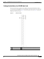
1
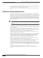
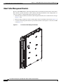
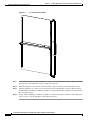
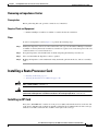
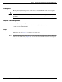
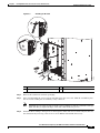
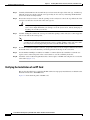
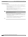
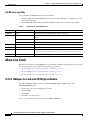
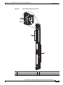
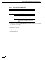
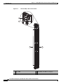
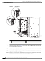
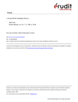
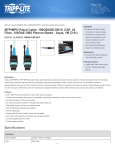
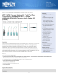
CH A P T E R
5
Installing Route Processor Cards, Line Cards, and
Fabric Cards
This chapter provides instructions on how to install cards and their associated components in the Cisco
NCS 6000 Line Card Chassis (LCC).
•
About Installing Cards and Associated Components, page 5-1
•
Installing and Removing an Impedance Carrier, page 5-5
•
Installing a Route Processor Card, page 5-7
•
Installing Fabric Cards, page 5-13
•
About Line Cards, page 5-22
•
Installing and Removing a Line Card, page 5-30
About Installing Cards and Associated Components
•
Preventing Electrostatic Discharge, page 5-1
•
Guidelines for Installing and Removing a Card, page 5-2
•
About Cable Management Brackets, page 5-4
Preventing Electrostatic Discharge
Electrostatic discharge (ESD) damage, which can occur when electronic cards or components are
improperly handled, results in complete or intermittent failures. We recommend use of an
ESD-preventive wrist strap whenever you handle network equipment or one of its components.
•
Always use an ESD-preventive wrist or ankle strap, and ensure that it makes good skin contact.
Connect the equipment end of the connection cord to an ESD jack (Figure 2-4) or a bare metal
surface on the chassis (ensure that the chassis is grounded).
•
Handle a card by its ejector levers, when applicable, or its metal carrier only; avoid touching the
board or connector pins (see the “Guidelines for Installing and Removing a Card” section on
page 5-2).
•
Place a removed card board-side-up on an antistatic surface or in a static-shielding bag. If you plan
to return the component to the factory, immediately place it in a static-shielding bag.
Cisco Network Convergence System 6000 Series Routers Hardware Installation Guide
5-1
Chapter 5
Installing Route Processor Cards, Line Cards, and Fabric Cards
About Installing Cards and Associated Components
•
Avoid contact between a card and clothing. The wrist strap protects the board from only ESD voltage
on the body; ESD voltage on clothing can still cause damage.
•
Be careful not to lay any tools on the aluminum honeycomb panel, or insert your fingers into the
panel.
Guidelines for Installing and Removing a Card
•
Every card has a label (with an arrow) on its faceplate showing which side is up for installation.
•
Every FC, LC, and RP card has a key mounted on the board that matches a corresponding slot on
the chassis side (top of each card slot). This key-slot mechanism prevents a card from being inserted
into the wrong, non-matching card slot. It also prevents a card from being inserted upside down.
When a card is inserted into the wrong card slot or upside down, the key will get blocked against the
chassis card guide and not slide though the slot. When the key gets blocked, remove the card and
find the correct card slot.
Note
•
RP card faceplates and the card slots on the LCC for RP cards are labeled with the square
symbol. FC faceplates and the card slots on the LCC for FCs cards are labeled with the circle.
symbol.
Online insertion and removal (OIR) is supported, enabling you to install a card while the LCC is
operating. OIR removes power to a specific slot before the card is replaced. The power remains on
for all other card slots.
OIR is seamless to users on the network, maintains all routing information, and ensures session
preservation. We recommend that you perform a graceful shutdown to shut down a fabric card prior
to removing it from the LCC. See Steps for OIR Fabric Card Removal, page 5-3.
•
When installing a fabric card, your must first push the OIR button on both the upper and lower
ejectors for the mechanical latch to be released.
•
The different cards in the LCC are all attached to the chassis itself using a pair of ejector levers and
captive screws. The two ejector levers release the card from its midplane connector. The exact
locations of the ejector levers and captive screws can vary slightly from card to card, but are
generally in the same locations: on the upper and bottom ends of the faceplate.
•
When you remove a card, always use the ejector levers first to ensure that the connector pins
disconnect from the midplane in the sequence expected by the chassis.
•
The chassis is shipped with all card slots containing either impedance carriers or a plastic cover to
help maintain chassis stiffness and prevent any damage to the chassis during shipment.
•
Any unused card slots that are uncovered would allow air used for chassis cooling to escape.
Therefore, to ensure proper air flow and maintain system EMC and safety compliance, any unused
LC slots must contain impedance carriers, and all FCs and RP cards must remain installed in their
card slots.
•
Fully insert all FCs and RP cards into the chassis before tightening their captive screws.
•
For information about the slot numbers, see the “Slot Numbers–Front and Rear Side” section on
page 2-5.
Cisco Network Convergence System 6000 Series Routers Hardware Installation Guide
5-2
Chapter 5
Installing Route Processor Cards, Line Cards, and Fabric Cards
About Installing Cards and Associated Components
Caution
The chassis may indicate a hardware failure if you do not follow proper procedures. Remove or install
only one card at a time. Allow at least 15 seconds for the chassis to complete its tasks before removing
or installing another card.
Steps for OIR Fabric Card Removal
Follow these steps to perform a graceful OIR on the fabric card by using the Cisco IOS XR shutdown
command.
Step 1
Shut down plane X (where X is in the range of 0 to 5).
config
controller fabric plane X
shutdown
commit
Step 2
Shut down FC card location R/FCS (where R is the rack number in the range of 0 to 15 and F0 to F3, and
S is the slot in the range of 0 to 5 for the LCC and 0 to 11 for the FCC).
config
hw-module location R/S shutdown
commit
…
…
Step 3
Unshut FC location.
config
no hw-module location R/S shutdown
commit
Step 4
Unshut plane X.
config
controller fabric plane X
no shutdown
commit
Cisco Network Convergence System 6000 Series Routers Hardware Installation Guide
5-3
Chapter 5
Installing Route Processor Cards, Line Cards, and Fabric Cards
About Installing Cards and Associated Components
About Cable Management Brackets
The Cisco NCS 6008 LCC has cable management features for both the front and rear sides of the chassis.
These features organize the interface cables entering and exiting the different cards, keeping them out
of the way and free of sharp bends that may damage the cables.
•
The front and rear sides have horizontal cable management brackets above and below the card cages
(Figure 3-2and
•
The front and rear sides have vertical cable troughs on the left and right of the chassis (Figure 3-4).
•
A vertical cable management bracket is preattached attached to the faceplate of a LC, FC, and RP
card (Figure 5-1).
LC Vertical Cable Management Bracket
304175
Figure 5-1
Cisco Network Convergence System 6000 Series Routers Hardware Installation Guide
5-4
Chapter 5
Installing Route Processor Cards, Line Cards, and Fabric Cards
Installing and Removing an Impedance Carrier
Installing and Removing an Impedance Carrier
The chassis ships with impedance carriers installed in the LC slots.
•
Installing an Impedance Carrier, page 5-5
•
Removing an Impedance Carrier, page 5-7
Installing an Impedance Carrier
This section describes how to install an impedance carrier in the Cisco NCS 6008 LCC.
Prerequisites
Before performing this task, open the cosmetic doors, if installed, and ensure that the slot in which you
are about to install the impedance carrier is empty.
Required Tools and Equipment
•
Number-2 Phillips screwdriver or number-2 common (flat-head) screwdriver
•
LC impedance carrier (Cisco PID NC6-LC-BLANK)
Steps
To install an impedance carrier (Figure 5-2), perform the following steps:
Cisco Network Convergence System 6000 Series Routers Hardware Installation Guide
5-5
Chapter 5
Installing Route Processor Cards, Line Cards, and Fabric Cards
Installing and Removing an Impedance Carrier
LC Slot Impedance Carrier
122147
Figure 5-2
Step 1
Use both hands while inserting an impedance carrier. Use one hand on the faceplate and the other hand
along the base of the impedance carrier to guide it into the slot.
Step 2
Slide the impedance carrier into the chassis until the captive screw plates are flush with the chassis.
Step 3
Partially tighten the two captive screws on the front panel of the impedance carrier (either by hand or
with the number-2 Phillips screwdriver or number-2 common (flat-head) screwdriver) to make sure that
they are both engaged.
Step 4
Use the number-2 Phillips screwdriver or number-2 common (flat-head) screwdriver to fully tighten the
captive screws to seat the impedance carrier firmly in the slot.
Cisco Network Convergence System 6000 Series Routers Hardware Installation Guide
5-6
Chapter 5
Installing Route Processor Cards, Line Cards, and Fabric Cards
Installing a Route Processor Card
Removing an Impedance Carrier
Prerequisites
Before performing this task, open the cosmetic doors, if installed.
Required Tools and Equipment
•
Number-2 Phillips screwdriver or number-2 common (flat-head) screwdriver
Steps
To remove an impedance carrier (Figure 5-2), perform the following steps:
Step 1
Identify the impedance carrier to be removed from the card cage. Use the number-2 Phillips screwdriver
or number-2 common (flat-head) screwdriver to turn the two captive screws on the front panel of the card
counterclockwise to loosen it from the slot.
Step 2
Grasp the impedance carrier handle with one hand and gently pull it halfway from the slot.
Step 3
Place one hand under the impedance carrier to guide it.
Step 4
Holding the impedance carrier underneath and by the handle, pull it from the slot, and set it carefully
aside.
Installing a Route Processor Card
•
Installing an RP Card, page 5-7
•
Verifying the Installation of an RP Card, page 5-10
Warning
Class 1 Laser Product. Statement 113
Warning
Because invisible radiation may be emitted from the aperture of the port when no fiber cable is
connected, avoid exposure to radiation and do not stare into open apertures. Statement 125
Installing an RP Card
Every Cisco NCS 6008 LCC contains two route processor (RP) cards in dedicated slots on the rear side
of the chassis. The RP cards are identical. One RP card installs into slot RP0 on the left of the card cage,
while the second RP card installs into slot RP1 on the right of the card cage.
Cisco Network Convergence System 6000 Series Routers Hardware Installation Guide
5-7
Chapter 5
Installing Route Processor Cards, Line Cards, and Fabric Cards
Installing a Route Processor Card
Prerequisites
Before performing this task, open the cosmetic doors, if installed. The RP cards are hot-swappable.
Caution
Install one RP card at a time. Allow at least 15 seconds for the chassis to complete its tasks before
installing another RP card. The chassis may indicate a hardware failure if you do not follow proper
procedures.
Required Tools and Equipment
•
ESD-preventive wrist strap
•
Number-2 Phillips screwdriver or number-2 common (flat-head) screwdriver
•
RP card (Cisco PID NC6-RP)
Steps
To install an RP card (Figure 5-3), perform the following steps:
Step 1
Attach the ESD-preventive wrist strap to your wrist and connect its leash to one of the two ESD jacks
on the rear side of the chassis (Figure 2-4). You can also connect the ESD-preventive wrist strap leash
to any bare metal surface on the chassis.
Cisco Network Convergence System 6000 Series Routers Hardware Installation Guide
5-8
Installing Route Processor Cards, Line Cards, and Fabric Cards
Installing a Route Processor Card
Figure 5-3
Installing an RP Card
3
2
1
304061
Chapter 5
1
Direction of insertion
2
Ejector lever
3
Captive screw
Step 2
Remove the card from its antistatic packaging.
Step 3
Place one hand under the card to support and guide it into the correct slot. Slide the card halfway into
the slot. Avoid touching the card circuitry or any connectors.
Note
Step 4
Alignment grooves exist on each slot in the card cage. When you install a card in the card cage,
make sure that you align both edges of the card carrier in the slot grooves.
Orient the RP according to the up arrow on the faceplate. If the card does not slide easily into the slot,
the orientation may be wrong or the slot is not for an RP. Reorient the RP, if necessary.
Cisco Network Convergence System 6000 Series Routers Hardware Installation Guide
5-9
Chapter 5
Installing Route Processor Cards, Line Cards, and Fabric Cards
Installing a Route Processor Card
Step 5
Carefully slide the RP into the slot until the ejector levers meet the edges of the card cage, and then stop
when the ejector lever hooks catch the card cage. If they do not catch, try reinserting the RP until the
ejector lever hooks are fully latched.
Step 6
Pivot both card ejector levers so that the openings on the card ejector cams at the top and bottom of the
card pass over the tabs on each side of the card cage slot.
Caution
Step 7
Verify that the openings on the card ejector cams pass over the tabs; otherwise, one or both
ejector levers might bind when you attempt to close the ejector levers, thereby damaging or
breaking one or both ejector levers.
Continue sliding the card into the card cage slot until the openings on the card ejector cams engage the
tabs on each side of the card cage slot.
Note
RP cards have guide pins that make initial contact with the backplane connector as you slide the
card into its slot. After the guide pins make contact, continue pushing on the card carrier until
the card ejector levers begin pivoting forward toward the handle in the card carrier.
Step 8
To seat the card in the backplane connector, grasp both card ejector levers and pivot them inward toward
the handle in the card carrier until they are flush against the front edge of the card carrier.
Step 9
Use the number-2 Phillips screwdriver or number-2 common (flat-head) screwdriver to turn the two
captive screws on the front panel of the card clockwise to seat the card firmly in the slot.
Step 10
Attach the vertical cable management bracket to the faceplate of the RP card using the two screws that
came with it (Figure 5-1).
Verifying the Installation of an RP Card
This section describes how to verify that the RP card has been properly installed and to troubleshoot the
installation in the Cisco NCS 6008 LCC.
Figure 5-4 shows the front panel of the RP card.
Cisco Network Convergence System 6000 Series Routers Hardware Installation Guide
5-10
Installing Route Processor Cards, Line Cards, and Fabric Cards
Installing a Route Processor Card
Figure 5-4
RP Card Front Panel
1
2
3
4
5
6
7
8
9
10
11
12
13
304080
Chapter 5
1
Status LED—Card status indicator
8
IEEE 1588 Ethernet port
2
Attention LED
9
SYNC0 (BITS/J.211) port
3
Expansion Ethernet ports
10 SYNC1 (BITS/J.211) port
4
Interface Shelf Ethernet ports
11 Time/Frequency Expansion port
5
Three console ports
GPS ToD interface
12 (with 1-PPS and 10-MHz coax connectors)
6
External USB port
13 Alarm port
7
Two management LAN Ethernet ports
Cisco Network Convergence System 6000 Series Routers Hardware Installation Guide
5-11
Chapter 5
Installing Route Processor Cards, Line Cards, and Fabric Cards
Installing a Route Processor Card
Troubleshooting the RP Card
Use the Status LED, located on the faceplate of the RP card, to verify the correct installation of the card:
Note
•
When the card is properly installed and no faults are detected, the card status LED turns green.
•
When the card status LED is solid yellow, either software initialization is in progress during bootup
or a fault exists on the board.
•
When the card status LED is blinking yellow, the card is not fully seated.
•
When the card status LED is off, verify that the card is installed correctly. There could be no power
applied to the card, a power fault, or a hardware fault.
•
Verify that there is power to the card by looking at the indicators on the power tray.
To confirm the location of the card that needs attention, the Attention LED can be lit by using the
hw-module attention-led location CLI command.
If the installed or replaced card fails to operate or to power on after installation:
•
Ensure that the card is seated firmly in the Cisco NCS 6008 chassis slot. One easy way to verify
physical installation is to see whether the front faceplate of the card is even with the fronts of the
other cards installed in the card cage.
•
Ensure that the ejector levers are latched and that the captive screws are fastened properly. If you
are uncertain, unlatch the levers, loosen the screws, and attempt to reseat the card.
•
Examine the power system to see whether the chassis is receiving power.
Step 11
Cisco Network Convergence System 6000 Series Routers Hardware Installation Guide
5-12
Chapter 5
Installing Route Processor Cards, Line Cards, and Fabric Cards
Installing Fabric Cards
Installing Fabric Cards
•
Installing a NC6-FC Fabric Card, page 5-13
•
Verifying the Installation of a NC6-FC Fabric Card, page 5-16
•
About Line Cards, page 5-22
Installing a NC6-FC Fabric Card
Prerequisites
Before performing this task, open the cosmetic doors, if installed.
Required Tools and Equipment
•
ESD-preventive wrist strap
•
Number-2 Phillips screwdriver or number-2 common (flat-head) screwdriver
•
Fabric Card (Cisco PID NC6-FC)
Steps
To install an FC (Figure 5-5), perform the following steps:
Cisco Network Convergence System 6000 Series Routers Hardware Installation Guide
5-13
Chapter 5
Installing Route Processor Cards, Line Cards, and Fabric Cards
Installing Fabric Cards
Figure 5-5
Installing a Fabric Card
3
2
347729
1
1
Ejector lever
2
OIR button
3
Captive screw
Step 1
Attach the ESD-preventive wrist strap to your wrist and connect its leash to one of the two ESD jacks
on the rear side of the chassis (Figure 2-4). You can also connect the ESD-preventive wrist strap leash
to any bare metal surface on the chassis.
Step 2
Remove the FC from its antistatic packaging.
Step 3
Place one hand under the card to support and position the card for insertion into the card cage slot. Avoid
touching the card circuitry or any connectors.
Note
Alignment grooves exist on each slot in the card cage. When you install a card in the card cage,
make sure that you align both edges of the card carrier in the slot grooves.
Step 4
Orient the FC according to the up arrow on the faceplate. If the card does not slide easily into the slot,
the orientation may be wrong or the slot is not for an FC. Reorient the FC, if necessary.
Step 5
If the ejector levers are locked in place, press the OIR buttons on the top and bottom of the card faceplate
to release the ejectors.
Cisco Network Convergence System 6000 Series Routers Hardware Installation Guide
5-14
Chapter 5
Installing Route Processor Cards, Line Cards, and Fabric Cards
Installing Fabric Cards
Step 6
Carefully slide the FC into the slot until the ejector levers meet the edges of the card cage, and then stop
when the ejector lever hooks catch the card cage. If they do not catch, try reinserting the FC until the
ejector lever hooks are fully latched.
Step 7
To seat the card in the midplane connector, grasp both card ejector levers and pivot them inward toward
the handle in the card carrier until they are flush against the front edge of the card carrier.
Note
New Installation Only. Do not tighten any fabric cards until all cards have been inserted and
seated. For maintenance and/or replacement of a failed FC card, only loosen or tighten the FC
card being replaced.
TIMESAVER: We recommend that you install the FC cards from either left to right or right to left to
avoid wedging a new FC card between two seated FC cards.
a.
Repeat steps 2 through 10 for all remaining FC cards.
Step 8
Use the number-2 Phillips screwdriver or number-2 common (flat-head) screwdriver to turn the two
captive screws on the front panel of the card clockwise to seat the card firmly in the slot.
Step 9
Attach the vertical cable management bracket to the faceplate of the FC using the two screws that came
with it (Figure 5-1).
Cisco Network Convergence System 6000 Series Routers Hardware Installation Guide
5-15
Chapter 5
Installing Route Processor Cards, Line Cards, and Fabric Cards
Installing Fabric Cards
Verifying the Installation of a NC6-FC Fabric Card
Figure 5-6
NC6-FC Front Panel
1
Status LED
3
32 CXP ports (left side 0 through 15, right side LEDs 16 though 31)
2
Attention LED
4
32 CXP port LEDs (one per port)
Cisco Network Convergence System 6000 Series Routers Hardware Installation Guide
5-16
Chapter 5
Installing Route Processor Cards, Line Cards, and Fabric Cards
Installing Fabric Cards
Fabric Card LEDs
Table 1 describes the LED indicators for the FCs.
•
The Status LED and Attention LED indicate the status of the S2 fabric card. Each LED is a bi-color
green and yellow LED.
•
The 32 CXP LEDs indicate the status of the CXP links. Each LED is a bi-color red and green LED.
Note that each FC slot must be configured as a fabric instance for the CXP LED to light up. For
example:
controller fabric plane 0
instance 0
location F0/FC0
Table 1
Fabric Card LED Indicators
LED
LED Color
Description
STATUS
Green
The card is properly installed and no faults are detected.
Yellow
The software initialization is in progress during bootup or a fault exists on the
board.
Flashing yellow (slow)
The card is not fully seated or the slot has detected a parity error.
Off
No power is applied to the card.
Blue
On: The card needs attention. Off: The card does not require attention.
ATTN
CXP (0-31) Green
The port is correctly connected to the NC6-FC on the LCC.
Red
One or more links are down. For troubleshooting information, see the System
Administration Command Reference for the Cisco NCS 6000 Series Routers.
Off
The CXP module is not present or is not fully inserted in the card.
Note
To verify which card needs attention, the Attention LED can be lit using the hw-module attention-led
location command.
If the installed or replaced FC fails to operate or power on after installation:
•
Ensure that the card is seated firmly in the FCC slot. One easy way to verify physical installation is
to see whether the front faceplate of the FC is even with the fronts of the other cards installed in the
card cage.
•
Ensure that the ejector levers are latched and that the captive screws are fastened properly. If you
are uncertain, unlatch the levers, loosen the screws, and attempt to reseat the FC.
•
Examine the power system to see whether the FCC is receiving power.
Cisco Network Convergence System 6000 Series Routers Hardware Installation Guide
5-17
Chapter 5
Installing Route Processor Cards, Line Cards, and Fabric Cards
Installing Fabric Cards
Installing an S13 MC Fabric Card
This section describes how to install an S13 Multi-Chassis (MC) fabric card in a Cisco NCS 6000 LCC
for multi-chassis configurations.
Prerequisites
•
Shut down the fabric plane (S13 slot number) if configured, to avoid traffic loss. The following
example shows how to shut down plane X (where X is in the range of 0 to 5).
config
controller fabric plane X
shutdown
commit
•
Open the cosmetic doors, if installed.
Required Tools and Equipment
•
ESD-preventive wrist strap
•
Number-2 Phillips screwdriver or Number-2 common (flat-head) screwdriver
•
S13 Multi-Chassis Fabric Card
Steps
To install an S13 MC FC card (Figure 5-5) in the NCS 6008 LCC, follow these steps:
Step 1
Attach the ESD-preventive wrist strap to your wrist and connect its leash to one of the two ESD jacks
on the rear side of the LCC (Figure 2-2). You can also connect the ESD-preventive wrist strap leash to
any bare metal surface on the FCC.
Step 2
Remove the card from its antistatic packaging.
Step 3
Determine the FC slot where the card will be installed. For a description of the slot locations, see
Figure 2-3.
Step 4
Orient the card according to the up arrow on the faceplate.
Note
If the card does not slide easily into the slot during installation, the orientation may be wrong or the slot
is not for a S13 MC FC.
Cisco Network Convergence System 6000 Series Routers Hardware Installation Guide
5-18
Chapter 5
Installing Route Processor Cards, Line Cards, and Fabric Cards
Installing Fabric Cards
Figure 5-7
1
Installing an S13 MC FC in a Cisco NCS 6008 LCC
3
Ejector lever
Captive screw
2 OIR buttons (top and bottom of faceplate)
Step 5
Place one hand under the card to support and position the card for insertion into the card cage slot. Avoid
touching the card circuitry or any connectors.
Note
Alignment grooves exist on each slot in the card cage. When you install a card in the card cage,
make sure that you align both edges of the card carrier in the slot grooves.
Cisco Network Convergence System 6000 Series Routers Hardware Installation Guide
5-19
Chapter 5
Installing Route Processor Cards, Line Cards, and Fabric Cards
Installing Fabric Cards
Step 6
If the ejector levers are locked in place, press the OIR buttons on the top and bottom of the card faceplate
to release the ejectors.
Step 7
Carefully slide the card into the slot until the ejector levers meet the edges of the card cage, and then
stop when the ejector lever hooks catch the card cage. If they do not catch, try reinserting the card until
the ejector lever hooks are fully latched.
Step 8
To seat the card in the midplane connector, grasp both card ejector levers and pivot them inward toward
the handle in the card carrier until they are flush against the front edge of the card carrier.
Tip
Step 9
For easier installation, install all FCs before securing any fasteners.
Use the number-2 Phillips screwdriver or number-2 common (flat-head) screwdriver to turn the two
captive screws on the front panel of the card clockwise to seat the card firmly in the slot.
Cisco Network Convergence System 6000 Series Routers Hardware Installation Guide
5-20
Chapter 5
Installing Route Processor Cards, Line Cards, and Fabric Cards
Installing Fabric Cards
Verifying the Installation of an S13 MC Fabric Card
This section describes how to verify that an S13 MC FC card is properly installed and is working
correctly in the Cisco NCS 6000 LCC. Use the Status LED, located on the faceplate of the card to verify
the correct installation of the card. Figure 5-8 shows the front panel of the card. Table 2 describes the
LED indicators and their meanings.
Figure 5-8
S13 MC Front Panel
1
Status LED
3
16 CXP port LEDs (0 through 15, one per port)
2
Attention LED
4
16 CXP ports
Cisco Network Convergence System 6000 Series Routers Hardware Installation Guide
5-21
Chapter 5
Installing Route Processor Cards, Line Cards, and Fabric Cards
About Line Cards
S13 MC Fabric Card LEDs
Table 2 describes the LED indicators for the S13 MC FC.
•
The Status LED and Attention LED indicate the status of the S13 MC fabric card. Each is a bi-color
green and yellow LED.
•
The16 CXP LEDs indicate the status of the CXP links. Each is a bi-color red and green LED.
Table 2
S13 MC Fabric Card LED Indicators
LED
LED Color
Description
STATUS
Green
The card is properly installed and no faults are detected
Yellow
The software initialization is in progress during bootup or a fault exists on the
board.
Flashing yellow (slow)
The card is not fully seated or the slot has detected a parity error.
Off
No power is applied to the card.
Blue
On: The card needs attention. Off: The card does not require attention.
ATTN
CXP (0 to 15) Green
The port is correctly connected to the S2 FC card on the FCC.
Red
One or more links are down. For troubleshooting information, see the System
Administration Command Reference for the Cisco NCS 6000 Series Routers.
Off
The CXP module is not present or is not fully inserted in the S13 MC FC.
About Line Cards
The line cards for the Cisco NCS 6008 chassis are monolithic assemblies with optical interfaces, packet
processing, and CPU control plane fully integrated onto one board.
•
10-Port 100Gbps Line Card with CPAK Optics Module, page 5-22
•
10-Port 100Gbps Line Card with CXP Optics Module, page 5-24
•
60-Port 10Gbps Line Card with SFP+ Optics Module, page 5-27
10-Port 100Gbps Line Card with CPAK Optics Module
The 10-port 100Gbps CPAK LC (Lean Core [NC6-10X100G-L-K] and Multi-Service Core
[NC6-10X100G-M-K]) has:
•
10 ports that each accept a CPAK optics module
•
Attention LED
•
Status LED
•
Port LEDs, one on each port
Figure 5-9 shows the front panel of the 10-port 100Gbps CPAK LC.
Cisco Network Convergence System 6000 Series Routers Hardware Installation Guide
5-22
Installing Route Processor Cards, Line Cards, and Fabric Cards
About Line Cards
Figure 5-9
10-Port 100Gbps CPAK LC Front Panel
1
2
3
3
303452
Chapter 5
1
Status LED
2
Attention LED
3
Port LEDs (one LED on each port)
Cisco Network Convergence System 6000 Series Routers Hardware Installation Guide
5-23
Chapter 5
Installing Route Processor Cards, Line Cards, and Fabric Cards
About Line Cards
Table 3 describes the LEDs for the 10-port 100Gbps CPAK LC.
Table 3
10-Port 100Gbps CPAK LC LED Descriptions
LED
State
Description
Status
Green
The LC is properly seated and operating correctly.
Yellow
The LC has one or more errors detected.
Off
No power is applied to the LC.
Blue
The card needs attention.
Off
The card does not need attention.
Green
The link is up (including internal loopback).
Yellow
The link is down or a hardware failure has occurred.
Off
The slice is unprovisioned by software, the optics
module is missing, or the slice has been powered
down.
Attention
Port
1
1. The Attention LED can only be lit by using the hw-module attention-led location CLI command which is useful for identifying
and verifying which card needs attention.
Physical Characteristics
•
Height—22.5 in. (57.2 cm)
•
Depth—15.75 in.(40 cm)
•
Width—2.1 in. (5.3 cm)
•
Weight—28 lb (12.8 kg)
10-Port 100Gbps Line Card with CXP Optics Module
The 10-port 100Gbps CXP LC (Lean Core [NC6-10X100G-L-P] and Multi-Service Core
[NC6-10X100G-M-P]) has:
•
10 ports that each accept a CXP optics module
•
Attention LED
•
Status LED
•
Port LEDs, one on each port
Figure 5-10 shows the front panel of the 10-port 100Gbps CXP LC.
Cisco Network Convergence System 6000 Series Routers Hardware Installation Guide
5-24
Installing Route Processor Cards, Line Cards, and Fabric Cards
About Line Cards
Figure 5-10
10-Port 100Gbps CXP LC Front Panel
1
2
3
3
303451
Chapter 5
1
Status LED
2
Attention LED
3
Port LEDs (one LED on each port)
Cisco Network Convergence System 6000 Series Routers Hardware Installation Guide
5-25
Chapter 5
Installing Route Processor Cards, Line Cards, and Fabric Cards
About Line Cards
Table 4 describes the LEDs for the 10-port 100Gbps CXP LC.
Table 4
10-Port 100Gbps CXP LC LED Descriptions
LED
State
Description
Status
Green
The LC is properly seated and operating correctly.
Yellow
The LC has one or more errors detected.
Off
No power is applied to the LC.
Blue
The card needs attention.
Off
The card does not need attention.
Green
The link is up (including internal loopback).
Yellow
The link is down or a hardware failure has occurred.
Off
The slice is unprovisioned by software, the optics
module is missing, or the slice has been powered
down.
Attention
Port
1
1. The Attention LED can only be lit by using the hw-module attention-led location CLI command which is useful for identifying
and verifying which card needs attention.
Physical Characteristics
•
Height—22.5 in. (57.2 cm)
•
Depth—15.75 in.(40 cm)
•
Width—2.1 in. (5.3 cm)
•
Weight—27 lb (12.2 kg)
Cisco Network Convergence System 6000 Series Routers Hardware Installation Guide
5-26
Chapter 5
Installing Route Processor Cards, Line Cards, and Fabric Cards
About Line Cards
60-Port 10Gbps Line Card with SFP+ Optics Module
The 60-port 10Gbps SFP+ LC (Lean Core [NC6-60X10GE-L-S] and Multi-Service Core
[NC6-60X10GE-M-S]) has:
•
60 ports that each accept a SFP+ optics module
•
Attention LED
•
Status LED
•
Port LEDs, one on each port
Figure 5-11 shows the front panel of the 60-port 10Gbps SFP+ LC.
Cisco Network Convergence System 6000 Series Routers Hardware Installation Guide
5-27
Chapter 5
Installing Route Processor Cards, Line Cards, and Fabric Cards
About Line Cards
Figure 5-11
60-Port 10Gbps SFP+ LC Front Panel
1
2
3
390402
3
1
Status LED
2
Attention LED
3
Port LEDs (one LED on each port)
Cisco Network Convergence System 6000 Series Routers Hardware Installation Guide
5-28
Chapter 5
Installing Route Processor Cards, Line Cards, and Fabric Cards
About Line Cards
Table 5-5 describes the LEDs for the 60-port 10Gbps SFP+ LC.
Table 5-5
60-Port 10Gbps SFP+ LC LED Descriptions
LED
State
Description
Status
Green
The LC is properly seated and operating correctly.
Yellow
The LC has one or more errors detected.
Off
No power is applied to the LC.
Blue
The card needs attention.
Off
The card does not need attention.
Green
The link is up (including internal loopback).
Yellow
The link is down or a hardware failure has occurred.
Off
The slice is unprovisioned by software, the optics
module is missing, or the slice has been powered
down.
Attention
Port
1
1. The Attention LED can only be lit by using the hw-module attention-led location CLI command which is useful for identifying
and verifying which card needs attention.
Physical Characteristics
•
Height—22.5 in. (57.2 cm)
•
Depth—15.75 in.(40 cm)
•
Width—2.1 in. (5.3 cm)
•
Weight—26 lb (11.8 kg)
Cisco Network Convergence System 6000 Series Routers Hardware Installation Guide
5-29
Chapter 5
Installing Route Processor Cards, Line Cards, and Fabric Cards
Installing and Removing a Line Card
Installing and Removing a Line Card
•
Installing a Line Card, page 5-30
•
Verifying the Installation of a Line Card, page 5-32
•
Removing a Line Card, page 5-33
Installing a Line Card
Prerequisites
Before performing this task, open the cosmetic doors, if installed.
Caution
Remove or install only one LC at a time. Allow at least 15 seconds for the chassis to complete its tasks
before removing or installing another LC. The chassis may indicate a hardware failure if you do not
follow proper procedures.
Required Tools and Equipment
•
ESD-preventive wrist strap
•
Number-2 Phillips screwdriver or number-2 common (flat-head) screwdriver
•
LC
Steps
To install a LC (Figure 5-12), perform the following steps:
Cisco Network Convergence System 6000 Series Routers Hardware Installation Guide
5-30
Chapter 5
Installing Route Processor Cards, Line Cards, and Fabric Cards
Installing and Removing a Line Card
Figure 5-12
Installing a LC
3
2
1
1
Direction of insertion
2
Ejector lever
3
Captive screw
Step 1
Attach the ESD-preventive wrist strap to your wrist and connect its leash to the ESD connection socket
on the front side of the chassis (Figure 2-4). You can also connect the ESD-preventive wrist strap leash
to any bare metal surface on the chassis.
Step 2
Remove the impedance carrier (see the “Removing an Impedance Carrier” section on page 5-7) and set
it aside.
Note
Remove only one impedance carrier and install one LC at a time. Be sure to verify that each LC
is fully installed and secured before installing another card.
Cisco Network Convergence System 6000 Series Routers Hardware Installation Guide
5-31
Chapter 5
Installing Route Processor Cards, Line Cards, and Fabric Cards
Installing and Removing a Line Card
Step 3
Remove the LC from the antistatic bag.
Step 4
Use both hands while inserting a LC. Use one hand on the faceplate and the other hand along the base
of the LC to guide it into a slot.
Caution
To prevent ESD damage, handle a LC by its ejector levers or the LC carrier edges only. Do
not touch any of the electrical components, pins, or circuitry.
Step 5
Orient the LC according to the up arrow on the faceplate. If the card does not slide easily into the slot,
the orientation may be wrong and the rejection flange is stopping the card from going into the slot.
Reorient the LC, if necessary.
Step 6
Make sure that the ejector levers are oriented properly to engage with the pin as the LC slides into the
slot. Carefully slide the LC into the slot until the ejector levers engage the catches, and then stop.
Step 7
Simultaneously pivot the ejector levers toward the faceplate of the LC. Do not force the LC; the ejector
levers properly seat the LC against the midplane.
Note
If the captive screws are difficult to tighten, ensure that each ejector lever is properly secured to
each catch and that the LC is properly seated in the slot.
Step 8
Use a number-2 Phillips screwdriver or number-2 common (flat-head) screwdriver to tighten the captive
screws next to each LC ejector lever to ensure proper EMI shielding and prevent the LC from becoming
partially dislodged from the midplane.
Step 9
Attach the vertical cable management bracket to the faceplate of the LC using the two screws that came
with it (Figure 5-1).
Verifying the Installation of a Line Card
Use the Status LED, located on the faceplate of the LC, to verify the correct installation of the LC:
•
When the card is properly installed and no faults are detected, the card status LED turns green.
•
When the card status LED is solid yellow, either software initialization is in progress during bootup
or a fault exists on the board.
•
When the card status LED is blinking yellow, the card is not fully seated.
•
When the card status LED is off, verify that the card is installed correctly. There could be no power
applied to the card, a power fault, or a hardware fault.
•
Verify that there is power to the card by looking at the indicators on the power tray.
If the installed or replaced LC fails to operate or to power on after installation:
•
Ensure that the card is seated firmly into the Cisco NCS 6008 chassis slot. One easy way to verify
physical installation is to see whether the front faceplate of the card is even with the fronts of the
other cards installed in the card cage.
•
Ensure that the ejector levers are latched and that the captive screws are fastened properly. If you
are uncertain, unlatch the levers, loosen the screws, and attempt to reseat the card.
•
Examine the power system to see whether the chassis is receiving power.
Cisco Network Convergence System 6000 Series Routers Hardware Installation Guide
5-32
Chapter 5
Installing Route Processor Cards, Line Cards, and Fabric Cards
Installing and Removing a Line Card
Removing a Line Card
Warning
Class 1 Laser Product. Statement 113
Warning
Because invisible radiation may be emitted from the aperture of the port when no fiber cable is
connected, avoid exposure to radiation and do not stare into open apertures. Statement 125
Warning
For diverging beams, viewing the laser output with certain optical instruments within a distance of
100 mm may pose an eye hazard. For collimated beams, viewing the laser output with certain optical
instruments designed for use at a distance may pose an eye hazard. Statement 282
Prerequisites
Before performing this task, open the cosmetic doors, if installed.
Caution
The system can indicate a hardware failure if you do not follow proper procedures. Remove or install
only one LC at a time. Allow at least 15 seconds for the system to complete its tasks before removing or
installing another LC.
Required Tools and Equipment
•
ESD-preventive wrist strap
•
Number-2 Phillips screwdriver or number-2 common (flat-head) screwdriver
Steps
To remove a LC (Figure 5-13), perform the following steps:
Cisco Network Convergence System 6000 Series Routers Hardware Installation Guide
5-33
Chapter 5
Installing Route Processor Cards, Line Cards, and Fabric Cards
Installing and Removing a Line Card
Figure 5-13
Removing a LC
1
2
304060
3
1
Captive screw
2
Ejector lever
3
Direction of removal
Step 1
Attach the ESD-preventive wrist strap to your wrist and connect its leash to the ESD connection socket
on the front side of the chassis (Figure 2-4). You can also connect the ESD-preventive wrist strap leash
to any bare metal surface on the chassis.
Step 2
Identify the card to be replaced. To verify which card needs attention, the Attention LED can be lit using
the hw-module attention-led location CLI command.
Step 3
Use the number-2 Phillips screwdriver or number-2 common (flat-head) screwdriver to loosen the two
captive screws holding the card in place.
Step 4
Grasp the two card ejector levers and simultaneously pivot both ejector levers 70 degrees away from the
front edge of the card carrier to unseat the card from the backplane connector.
Cisco Network Convergence System 6000 Series Routers Hardware Installation Guide
5-34
Chapter 5
Installing Route Processor Cards, Line Cards, and Fabric Cards
Installing and Removing a Line Card
Step 5
Warning
Touching only the metal card carrier, slide the card from the slot and place it directly into an antistatic
sack or other ESD-preventive container.
Because invisible laser radiation may be emitted from the aperture of the port when no cable is
connected, avoid exposure to laser radiation and do not stare into open apertures. Statement 70
Cisco Network Convergence System 6000 Series Routers Hardware Installation Guide
5-35
Chapter 5
Installing Route Processor Cards, Line Cards, and Fabric Cards
Installing and Removing a Line Card
Cisco Network Convergence System 6000 Series Routers Hardware Installation Guide
5-36