1
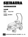
OPERATOR'S MANUAL
MODEL
SX21
SX24
TRACTOR
SXM54
SXM60 MOWER
TO THE OWNER
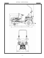
This manual contains information concerning the adjustment and maintenance of your SHIBAURA
Model SX21 and SX24. You have purchased a dependable machine, but only by proper care and
operation can you expect to receive the performance and long service built into this tractor. Please
have all operators read this manual carefully and keep it available for ready reference.
This machine was designed to power and propel itself. It is intended to pull or carry tractor attachments
or load and move materials when equipped with a front end loader with a variety of buckets. Only
attachments recommended and approved by SHIBAURA should be used with your tractor.
Your SHIBAURA dealer will instruct you in the general operation of your tractor. (Refer to the "Delivery
Report" at the back of this manual.) Your dealer's staff of factory-trained service technicians will be
glad to answer any questions that may arise regarding the operation of your tractor.
Your SHIBAURA dealer carries a complete line of genuine SHIBAURA service parts. These parts are
manufactured and carefully inspected to insure high quality and accurate fitting of any necessary
replacement parts. Be prepared to give your dealer the model and serial number of the tractor, when
ordering parts. Locate these numbers now and record them below. Refer to the "General Information"
section of this manual for the location of the model and serial numbers of your tractor.
Model __________________________________
Serial Number ____________________________
CAUTION
This safety alert symbol indicates important safety messages in this manual. When you see this
symbol, carefully read the message that follows and be alert to the possibility of personal injury
or death.
CAUTION
Pictures in this manual may show protective shielding open or removed to better illustrate a
particular feature or adjustment.
Be certain, however, to close or replace all shielding before operating the machine.
IMPROVEMENTS
SHIBAURA, Inc. is continually striving to improve its products. We reserve the right to make
improvements or changes when it becomes practical and possible to do so, without incurring any
obligation to make changes or additions to the equipment sold previously.
0-1
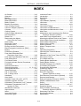
CONTENTS
SAFETY ································································································································ 0-5
GENERAL INFORMATION ··································································································· 1-1
OPERATION ························································································································· 2-1
LUBRICATION AND MAINTENANCE·················································································· 3-1
SXM54, SXM60 MOWER DECK ··························································································· 4-1
SPECIFICATIONS················································································································· 5-1
INDEX···································································································································· 5-8
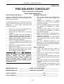
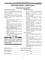
PRE-DELIVERY SERVICE ································································································· 5-10
PRE-DELIVERY CHECKLIST····························································································· 5-12
0-2
Electro-magnetic Interference (EMC)
This tractor complies strictly with the European Regulations on electro-magnetic emissions.
However, interference may arise as a result of add-on equipment which may not necessarily
meet the required standards. As such interference can result in serious malfunction of the unit
and/or create unsafe situations, you must observe the following:
●
Ensure that each piece of non-SHIBAURA equipment fitted to the tractor bears the CE mark.
●
The maximum power of emission equipment (radio, telephones, etc.) must not exceed the
limits imposed by the national authorities of the country where you use the tractor.
●
The electro-magnetic field generated by the add-on system should not exceed 24V/m at any
time and at any location in the proximity of electronic components.
Failure to comply with these rules will render the SHIBAURA warranty null and void.
0-3
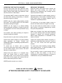
PRECAUTIONARY
STATEMENTS
PERSONAL SAFETY
PERSONAL SAFETY
Throughout this manual and on machine decals, you will find precautionary statements
(“CAUTION”, ”WARNING”, and “DANGER”) followed by specific instructions. These specifications are
intended for the personal safety of you and those working with you. Please take the time to read them.
The word “CAUTION” is used where a safe behavioral practice according to operating
and maintenance instructions and common safety practices will protect the operator and
others from accident involvement.
The word “WARNING” denotes a potential or hidden hazard, which has a potential for
serious injury. It is used to warn operators and others to exercise every appropriate
means to avoid a surprise involvement with machinery.
The word “DANGER” denotes a forbidden practice in connection with a serious hazard.
Failure to follow the “CAUTION”, “WARNING”, and “DANGER” instructions may result in bodily injury
or death.
MACHINE SAFETY
The precautionary statement ("IMPORTANT") is followed by specific instructions. This statement is
intended for machine safety.
IMPORTANT: The word "IMPORTANT" is used to inform the reader of something he needs to know
to prevent minor machine damage if a certain procedure is not followed.
INFORMATION
NOTE: Instructions used to identify and present supplementary information.
0-4
SAFETY
PRECAUTIONARY STATEMENTS
A careful operator is the best operator. Most accidents can be avoided by observing certain
precautions. To help prevent accidents, read the following precautions before operating this equipment.
Equipment should be operated only by those who are responsible and instructed to do so.
Carefully review the procedures given in this manual with all operators. It is important that all operators
be familiar with and follow safety precautions.
THE TRACTOR
1. Read the Operator's Manual carefully
before using the tractor. Lack of operating
knowledge can lead to accidents.
2. Use an approved roll bar for safe
operation. Overturning a tractor without a
roll bar can result in death or injury. If
your tractor is not equipped with a roll
bar, see your SHIBAURA Dealer.
3. Keep the tractor and equipment, particularly
brakes and steering, maintained in a reliable
and satisfactory condition to ensure your
safety and comply with legal requirements.
4. Keep open flame or cold weather starting
aids away from the battery to prevent
fires or explosions. Use jumper cables
according to instructions to prevent
sparks which could cause explosion.
3. Use the handholds and step plates when
getting on and off the tractor to prevent
falls. Keep steps and platform cleared of
mud and debris.
5. Stop the engine before performing any
service on the tractor.
4. Do not permit anyone but the operator to
ride on the tractor. There is no safe place
for extra riders.
6. Escaping hydraulic/diesel fluid under
pressure can penetrate the skin causing
serious injury. If fluid is injected into the
skin, obtain medical attention immediately
or gangrene may result.
5. Keep all safety decals clean of dirt and
grime, and replace all missing, illegible,
or damaged safety decals. See the list of
decals in the decal section of this manual.
SERVICING THE TRACTOR
1. The cooling system operates under
pressure which is controlled by the
radiator cap. It is dangerous to remove
the cap while the system is hot. Always
turn the cap slowly to the first stop and
allow pressure to escape before removing
the cap entirely.
2. Keep any type of open flame away from
the tractor and do not smoke while
refueling. Wait for the engine to cool
before refueling.
0-5
• DO NOT use your hand to check for
leaks. Use a piece of cardboard or
paper to search for leaks.
• Stop the engine and relieve pressure
before connecting or disconnecting
lines.
• Tighten all connections before starting
the engine or pressurizing lines.
7. Do not modify or permit anyone else to
modify or alter this tractor or any of its
components or functions without first
consulting a SHIBAURA Dealer.
8. The fuel oil in the injection system is
under high pressure and can penetrate
the skin. Unqualified persons should not
remove or attempt to adjust a pump,
injector, nozzle, or any other part of the
fuel injection system. Failure to follow
these instructions can result in serious
injury.
9. Continuous long-term contact with used
engine oil may cause skin cancer. Avoid
prolonged contact with used engine oil.
Wash skin promptly with soap and water.
8. If the power steering or engine ceases
operating, stop the tractor immediately.
9. Pull only from the drawbar or the lower
link drawbar in the down position. Use
only a drawbar pin that locks in place.
Pulling from the tractor rear axle or any
point above the axle may cause the
tractor to upset.
OPERATING THE TRACTOR
10. If the front end of the tractor tends to rise
when heavy implements are attached to
the three-point hitch, install front end or
front wheel weights. Do not operate the
tractor with a light front end.
1. Before starting the tractor, apply the
parking brake, place the PTO lever in the
"OFF" position, the lift control lever in the
down position, the remote control valve
levers in the neutral position, and the
transmission in neutral.
11. Always set the hydraulic selector lever in
position control when attaching or
transporting equipment. Ensure hydraulic
couplers are properly mounted and will
disconnect safely in case of accidental
detachment of implement.
2. Always sit in the tractor seat when
starting the engine or operating controls.
Do not start the engine or operate
controls while standing beside the
tractor.
12. Do not leave equipment in the raised
position.
3. Do not bypass the neutral start switches.
Consult your SHIBAURA Dealer if your
neutral start controls malfunction. Use
jumper cables only in the recommended
manner. Improper use can result in
tractor runaway.
4. Avoid accidental contact with the gear
shift lever while the engine is running, as
this can cause unexpected tractor
movement.
5. Before getting off the tractor, disengage
the PTO, turn the engine off, and apply
the parking brake. Never get off the
tractor while it is in motion.
6. Do not park the tractor on a steep incline.
7. Do not operate the tractor engine in an
enclosed building without adequate
ventilation. Exhaust fumes can cause
death or illness.
0-6
13. Use the flasher/turn signal lights when
traveling on public roads both day and
night (unless prohibited by law).
14. When operating at night, adjust lights to
prevent blinding oncoming drivers.
DRIVING THE TRACTOR
1. Watch where you are going, especially at
row ends, on roads, around trees and low
hanging obstacles.
2. To avoid upsets, drive the tractor with
care and at a safe speed. Use extra
caution when operating over rough
ground, when crossing ditches or slopes,
and when turning corners.
4. To avoid injury, do not clean, adjust,
unclog, or service PTO driven equipment
when the tractor engine is running.
5. Ensure the PTO master shield is installed
at all times. Always replace the PTO
shield cap when the PTO is not in use.
DIESEL FUEL
4. Do not coast or free wheel down hills.
Use the same gear when going downhill
as is used when going uphill.
1. UNDER NO CIRCUMSTANCES should
gasoline, alcohol, or blended fuels be
added to diesel fuel. These combinations
can create an increased fire or explosive
hazard. Such blends are more explosive
than pure gasoline in a closed container
such as a fuel tank. DO NOT USE THESE
BLENDS.
5. Any towed vehicle with a total weight
exceeding that of the towing tractor
should be equipped with brakes for safe
operation.
2. Never remove the fuel cap or refuel with
the engine running or hot.
3. Do not smoke while refueling or when
standing near fuel.
6. If the tractor becomes stuck or the tires
become frozen to the ground, back up the
tractor to prevent upset.
4. Maintain control of the fuel filler pipe
nozzle when filling the tank.
3. To provide two-wheel braking, one pedal
actuates both brakes.
7. Always check overhead clearance,
especially when transporting the tractor.
5. Do not fill the fuel tank to capacity. Allow
room for expansion.
6. Wipe up spilled fuel immediately.
8. When operating at night, adjust lights to
prevent blinding oncoming drivers.
OPERATING THE PTO
1. When operating PTO driven equipment,
shut off the engine and wait until the PTO
stops before getting off the tractor and
disconnecting the equipment.
2. Do not wear loose clothing when
operating the power take-off or when near
rotating equipment.
7. Always tighten the fuel tank cap securely.
8. If the original fuel tank cap is lost, replace
it with SHIBAURA approved cap. A
non-approved proprietary cap may not be
safe.
9. Keep equipment
maintained.
clean
and
properly
10. Do not drive equipment near open fires.
11. Never use fuel for cleaning purposes.
3. When operating stationary PTO driven
equipment, always place both gear shift
levers in neutral, apply the tractor parking
brake, and block the rear wheels front
and back.
0-7
12. Arrange fuel purchases so that winter
grade fuels are not held over and used in
the spring.
SAFETY FRAME (ROPS)
Your SHIBAURA is equipped with a safety
framer. It must be maintained in a serviceable
condition. Be careful when driving through
doorways or working in confined spaces with
low headroom.
UNDER NO CIRCUMSTANCES should you:
• modify, drill, or alter the safety frame in any
way. Doing so may render you liable to
legal prosecution.
• attempt to straighten or weld any part of the
main frame or retaining brackets which
have suffered damage. Doing so may
weaken the structure and endanger your
safety.
• secure any parts on the main frame or
attach your safety frame with anything
other than the special high tensile bolts and
nuts specified.
• attach chains or ropes to the main frame for
pulling purposes.
• take unnecessary risks even though your
safety frame affords you the maximum
protection possible.
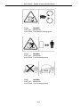
WHEN YOU SEE THIS SYMBOL
IT MEANS:
ATTENTION!
BECOME ALERT!
YOUR SAFETY IS INVOLVED!
0-8
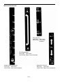
SAFETY DECALS
The following safety decals have been placed on your machine in the areas indicated. They are
intended for your personal safety and for those working with you. Please take this manual and walk
around your machine to note the content and location of these warning signs. Review these warning
signs and the operating instructions detailed in this manual with your machine operators.
Keep the decals legible. If they are not, obtain re placements from your authorized dealer. The decal
replacement part numbers are listed with each decal.
SAFETY DECALS
WARNING: Keep Hands and Clothing
away from Rotation Fan.
PART NO: 390198020
LOCATION: Rear of radiator
DANGER: ROPS
PART NO: 390198010
LOCATION: Left-hand/inside
of ROPS
WARNING: Radiator Cap
PART NO: 490992480
LOCATION: On radiator cap
DANGER:
PART NO: 390197900
LOCATION: • In Front of Operator's Seat
• Inside of hood
WARNING: BATTERY
PART NO: 490992480
LOCATION: On Battery Holddown
0-9
INSTRUCTION DECALS
Drop Rate Valve
PART NO: 390372470
LOCATION: Top of Drop Rate Knob
Engine Oil
PART NO: 390230220
LOCATION: On Engine Oil Filler Cap
Range Selector Lever
PART NO: 390174181
LOCATION: Left Control Pod
Air Cleaner Servicing
PART NO: 390198940
LOCATION: Air Cleaner End Cap
Starter Switch
PART NO: 390197280
LOCATION: On the RH of Dash
Diesel Fuel
PART NO: 490992430
LOCATION: Near Fuel Cap
0-10
INSTRUCTION DECALS
Hand Throttle
PART NO: 390430290
LOCATION: RH side of Console
(Optional)
Operating Remote Control Valve - Single
PART NO: 390370300
LOCATION: Inboard Station RH Control Pod
Front-Wheel Drive Control Lever
PART NO: 390173871
LOCATION: In Front of Operator's Seat
Right Side of Platform
Adjusting Cutting Height
PART NO: 390198950
LOCATION: Left Control Quadrant
Parking Brake
PART NO: 390198361
LOCATION: Near Parking Brake
0-11
INSTRUCTION DECALS
PTO Selection
PART NO: 390174191
LOCATION: Left Control
Quadrant
PTO Engagement
PART NO: 390174201
LOCATION: Right Control Quadrant
Mower Height Adjustment
PART NO: 390174212
LOCATION: Left Control Quadrant
Hydraulic Power Lift
PART NO: 390372541
LOCATION: Right Control Quadrant
0-12
0-13
ECOLOGY AND THE ENVIRONMENT
Soil air, and water are vital factors of agriculture
and life in general. When legislation does not yet
rule the treatment of some of the substances
which are required by advanced technology,
common sense should govern the use and
disposal of products of a chemical and
petrochemical nature.
2. In general, avoid skin contact with all fuels,
oils, acids, solvents, etc. Most of them contain
substances which may be harmful to your
health.
The following are recommendations which may
be of assistance:
4. Avoid spillage when draining off used engine
coolant mixtures, engine, gearbox and
hydraulic oils, brake fluids, etc. Do not mix
drained brake fluids or fuels with lubricants.
Store them safely until they can be disposed
of in a proper way to comply with local
legislation and available resources.
•
•
Become acquainted with and ensure that you
understand the relative legislation applicable
to your country.
Where no legislation exists, obtain
information from suppliers of oils, filters,
batteries, fuels, antifreeze, cleaning agents,
etc., with regard to their effect on man and
nature and how to safely store, use and
dispose of these substances. Agricultural
consultants will, in many cases, be able to
help you as well.
HELPFUL HINTS
1. Avoid filling tanks using cans or inappropriate
pressurized fuel delivery systems which may
cause considerable spillage.
0-14
3. Modern oils contain additives. Do not burn
contaminated fuels and or waste oils in
ordinary heating systems.
5. Modern coolant mixtures, i.e. antifreeze and
other additives, should be replaced every two
years. They should not be allowed to get into
the soil but should be collected and disposed
of safely.
6. Repair any leaks or defects in the engine
cooling or hydraulic system immediately.
7. Do not increase the pressure in a pressurized
circuit as this may lead to a component
failure.
8. Protect hoses during welding as penetrating
weld splatter may burn a hole or weaken them,
allowing the loss of oils, coolant, etc.
UNIVERSAL SYMBOLS
As a guide to the operation of your tractor, various universal symbols have been utilized on the
instruments, controls, switches, and fuse box. The symbols are shown below with an indication of their
meaning.
0-15
0-16
SECTION 1
GENERAL INFORMATION
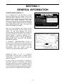
PLEASE READ CAREFULLY:
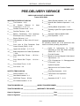
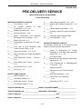
For a complete list of the pre-delivery service
checks performed by your dealer, refer to the
PRE-DELIVERY SERVICE check list found at
the back of this manual. Keep one copy as your
record of the service performed. The other
should be removed from the manual and kept by
your dealer. MAKE SURE THAT BOTH COPIES
ARE COMPLETED AND THAT YOU AND THE
DEALER SIGN BOTH COPIES.
After you have operated your tractor for fifty
hours, take this manual and your tractor to your
dealer. He will then perform the factory
recommended 50-HOUR SERVICE as listed on
the lower portions at the back of this manual —
without charge — except for lubricant, oil, or
filters replaced as part of normal maintenance.
MAKE SURE THAT YOU AND THE DEALER
SIGN BOTH COPIES.
A PRODUCT IDENTIFICATION PLATE is
located on the right-hand side of the front frame.
The numbers on the plate are important should
your tractor require future service. For your
convenience, have your dealer record the
numbers in the appropriate spaces below.
SHIBAURA policy is one of continuous
improvement, and the right to change prices,
specification or equipment at any time without
notice is reserved.
All data given in this manual is subject to
production variations. Dimensions and weights
are approximate only and the illustrations do not
necessarily show tractors in standard condition.
For exact information about any particular tractor
please consult your SHIBAURA Tractor Dealer.
1-1
SECTION 1 – GENERAL INFORMATION
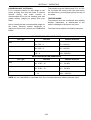
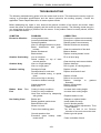
METRIC BOLT TORQUE SPECIFICATION
Coarse Thread
Bolt Size
Grade No.
Pitch (mm)
Pounds-Feet
Newton Meters
Pitch (mm)
Pounds-Feet
Newton-Meters
3.6 – 5.1
4.9 – 6.9
6.1 – 8.3
8.3 – 11.3
–
–
–
8.7 – 11.6
11.8 – 15.7
9.4 – 12.3
12.7 – 16.7
11.2 – 14.8
15.2 – 20.1
16.6 – 21.0
22.6 – 28.4
19.5 – 25.3
26.5 – 34.3
10T
21.0 – 26.8
28.4 – 36.3
22.4 – 29.7
30.4 – 40.2
4T
18.8 – 24.6
25.5 – 33.3
21.0 – 26.8
28.4 – 36.3
32.5 – 41.2
44.1 – 55.9
36.2 – 46.3
49.0 – 62.8
10T
39.8 – 51.4
53.9 – 69.6
42.7 – 54.2
57.9 – 73.5
4T
27.5 – 34.7
37.3 – 47.1
31.8 – 40.5
43.1 – 54.9
48.5 – 61.5
65.7 – 83.4
55.0 – 69.4
74.5 – 94.1
10T
68.0 – 85.4
92.2 – 116
73.1 – 93.3
99.0 – 127
4T
46.3 – 59.3
62.8 – 80.4
51.4 – 64.4
69.6 – 87.3
76.7 – 96.9
104 – 131
86.1 – 109
117 – 148
11T
102 – 129
139 – 175
108 – 137
147 – 186
4T
63.6 – 81.0
86.3 – 110
67.3 – 84.6
91.2 – 115
110 – 136
149 – 184
116 – 142
157 – 192
11T
152 – 188
206 – 255
163 – 199
221 – 270
4T
83.9 – 104
114 – 141
96.9 – 120
131 – 163
145 – 174
196 – 235
170 – 206
230 – 279
11T
203 – 246
275 – 333
221 – 271
299 – 368
4T
106 – 132
144 – 179
127 – 156
172 – 211
177 – 213
240 – 289
203 – 246
275 – 333
268 – 325
363 – 441
293 – 358
397 – 485
4T
M6
1.0
7T
10T
4T
M8
M10
M12
M14
M16
M18
M20
Fine Thread
7T
7T
7T
7T
7T
7T
7T
11T
1.25
1.5
1.75
2.0
2.0
2.0
2.5
1-2
1.0
1.25
1.25
1.5
1.5
1.5
1.5
SECTION 2
OPERATION
CONTROLS AND INSTRUMENTS
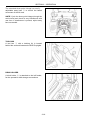
SEAT, SEAT BELT, AND ROLLOVER
PROTECTIVE STRUCTURE (ROPS)
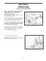
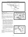
Adjusting the Tractor Seat
Your SHIBAURA Tractor equipped with an
adjustable suspension seat.
To adjust the seat fore and aft, move the release
lever ①, towards the fender, slide the seat to the
desired position, releasing the lever to lock.
③
① ②
The seat has seven height position controlled by
the knob ②. While sitting in the seat, pull out the
knob moving it to the left to increase the height,
or to the right to reduce the height.
To adjust the seat suspension for individual
operators; with moving the lever ③ straight up,
turn it clockwise to be for (+) and turn it
counter-clockwise to be for less (-).
Your tractor equipped with a mirror.
To adjust the mirror, loosen the screw tightened
clamp for repositioning the mirror.
2-1
SECTION 2 – OPERATION
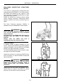
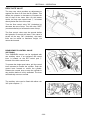
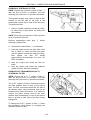
ROLLOVER PROTECTIVE STRUCTURE
(ROPS)
Your tractor is equipped with a folding Roll Over
protective Structure (ROPS). If, for some reason,
the ROPS was deleted by the original or has
been removed. It is recommended that you equip
your tractor with a ROPS.
ROPS are effective in reducing injuries during
tractor overturn accidents. Overturning tractor
without a ROPS can result in serious injury or
death.
Roll Over Protective Structure (ROPS), is
available from your SHIBAURA Tractor Dealer.
WARNING
When improperly operated, a tractor can roll
over. For low clearance use only, the ROPS
may be lowered.
No protection is provided when the tractor is
operated with the ROPS in the lowered
position.
Always raise the ROPS and lock it
immediately after low clearance work.
Folding the ROPS
A foldable ROPS is factory installed on your
tractor. Operate with ROPS in the raised position
whenever possible. Use the ROPS in the folded
position only when absolutely necessary.
To fold the ROPS remove two lock pins, lower
the upper of the ROPS rearward.
Install two lock pins to anchor the ROPS firmly
once in position. To raise the ROPS reverse the
above procedure.
WARNING
Do not operate the tractor with the ROPS
folded as a standard operating mode. A
folded ROPS does not provide rollover
protection.
Always pull from the tractor the drawbar. Do no
attach chains or ropes to the ROPS for pulling
purposes, as the tractor can tip backwards.
2-2
SECTION 2 – OPERATION
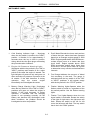
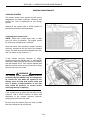
INSTRUMENT PANEL
⑥⑦
⑥⑦
⑧
⑤
②
⑨
⑫
⑪
④
1. Cold Starting Indicator Light – Illuminate
when the key switch is turned to the "HEAT"
position. It remains lit for approximately 5
seconds when the key is held in position,
during which time the glow plugs are heating
the precombustion chambers.
⑩
③
①
4. Proof Meter-Records the hours and portions
of hours that your tractor has been operated
based on an average engine speed of 3000
RPM. Engine speeds below 3000 RPM accumulate engine hours at a slower rate than
clock hours. Engine speeds above 3000
RPM accumulate engine hours faster than
clock hours. Use the proof meter as a guide
to determine hourly service and maintenance
intervals.
2. Engine Oil Pressure Warning LightIlluminates with the key switch in the "ON" or
"HEAT" positions and remains lit for a short
period of time after the engine is started. The
light indicates oil pressure only and goes out
when sufficient oil pressure is present at the
oil sender. If the bulb becomes lit during
operation,
stop
the
tractor
engine
immediately and investigate the cause.
5. Fuel Gauge-Indicates the amount of diesel
fuel remaining in the tank. The gauge is
activated when the key switch is in the "ON"
or "HEAT" positions. It will register empty
with the key switch in the "STOP" position.
3. Battery Charge Warning Light- Illuminates
when the key switch is in the "ON" or "HEAT"
positions and goes out when the engine is
started. If this bulb becomes lit during
operation, it indicates that the charging
system is not operating normally. As the
battery can become fully discharged under
these conditions, the problem should be
investigated as soon as possible.
6. Flasher Warning Lights-Operate when the
flasher switch is turned on, regardless of the
key switch position. Use the flasher warning
lights.
7. Flasher Turn Lights-Operate when the turn
signal switch is activated. Rotate the switch
to the right for right turns, the right arrow will
flash. Rotate the switch to the left for left
turns, the left arrow will flash. The key switch
has to be in the "RUN" position.
2-3
SECTION 2 – OPERATION
8. Temperature
Gauge-Indicates
coolant
temperature. It is activated when the key
switch is turned to the "ON" or "HEAT"
positions. The gauge will register cold with
the key switch in the "STOP" position. If the
needle registers in the green range of the
gauge, this indicates a normal operating
temperature. If the needle moves to the red
portion of the gauge, this indicates an
overheated condition. Stop the tractor engine
immediately and investigate the cause.
10. Rear PTO Speed-Determined by the position
of the needle on the tachometer. The
tachometer is marked to indicate 540 PTO
RPM. Engine RPM should remain close to
this mark while using the rear PTO; running
the engine faster than this results in a
dangerous overspeed condition.
11. High Beam Indicator – Illuminates when the,
head-lights are switched to main beam.
12. Parking Brake Light – Illuminates if the
parking brake is engaged when the key
switch is turned from "OFF" position.
9. Tachometer-Registers
engine
RPM
(Revolutions Per Minute). The gauge is
marked in increments of 100 and will return
to zero when the engine is not running.
2-4
SECTION 2 – OPERATION
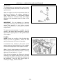
KEY SWITCH
The key switch ① is located on the right-hand
side of the console, just below the hand throttle.
Turning the key clockwise, to the "ON" position,
activates the warning lights and instruments. The
pre-heat system is activated when the key is
turned farther clockwise to the "HEAT" position,
and the engine starts when the key is turned to
the extreme right. The key spring returns to the
"ON" position when released.
①
PRE-HEATING THE SYSTEM
Your tractor has a diesel engine. Before starting
a cold engine, the precombustion chambers
must be heated.
To pre-heat the engine, turn the key switch to the
"HEAT" position and hold the key in this position
for approximately 5 seconds. The glow plugs
heat the precombustion chambers during this
time, and the engine will start.
NOTE: When ambient temperatures are colder,
a longer pre-heat time is necessary. Even after
the cold start indicator light has gone out, the
glow plugs will continue to heat if the key is held
in the "HEAT" position.
2-5
SECTION 2 – OPERATION
STARTING THE ENGINE
The key switch ① allows activation of the starter
motor and fuel delivery only when:
①
1. The PTO clutch lever ②
"disengaged" position.
is in the
②
2-6
SECTION 2 – OPERATION
2. The range lever ③ is in the "NEUTRAL"
position.
3. The operator is sitting in the seat OR the
parking brake is engaged.
③
NOTE: Always use safe practices when starting
your tractor. Turn the key to the extreme right.
Position the hand throttle forward so that it is
one-fourth to one-third open.
WARNING
Always sit in the operator's seat when
starting the tractor. Never attempt to start the
engine while standing beside the tractor.
IMPORTANT: Do not engage the starting motor
continuously for more than 30 seconds. Doing so
may cause starting motor failure.
2-7
SECTION 2 – OPERATION
STARTING THE TRACTOR WITH JUMPER
CABLES
STOPPING THE ENGINE
Turn the key switch to the "OFF" position to stop
the engine.
WARNING
Start the engine only from the operator's seat.
If safety start switches are bypassed, the
engine can start with the transmission and/or
PTO in gear.
If you must use jumper cables to start the tractor:
BREAK-IN PROCEDURES
Your SHIBAURA tractor will provide long and
dependable service if given proper care during
the first 50-hour break-in period. During the first
50 hours of operation:
1. Avoid "lugging" the engine. Operating in too
high a gear under heavy load may cause
engine lugging, which is indicated when the
engine will not respond to a throttle increase.
1. Shield your eyes.
2. Connect one end of the jumper cable to the
tractor battery positive (+) terminal and the
other to the auxiliary battery positive (+)
terminal. Next, connect one end of the other
jumper cable first to the auxiliary battery
negative (-) terminal, then the other end to
the tractor starter ground terminal. Finally,
start the tractor by following the safe starting
procedures outlined under "Starting the
Engine." Idle the engine and turn on all
electrical equipment (lights, etc.), then
disconnect the jumper cables in the reverse
order in which they were connected. This
helps protect the alternator from damage due
to extreme load changes.
2. Use the lower gear ratios when pulling heavy
loads and avoid continuous operation at
constant engine speeds. You will save fuel
and minimize engine wear by selecting the
correct gear ratio for a particular operation.
Operating the tractor in low gear with a light
load and high engine speed wastes fuel.
3. Avoid prolonged operation at either high or
low engine speeds without a load on the
engine.
4. Check the instruments frequently and keep
the radiator and oil reservoirs filled to
recommended levels. Daily checks include
the engine oil level, radiator coolant, and air
cleaner.
WARNING
Batteries contain sulfuric acid and produce
explosive gases. To prevent personal injury:
• Wear eye and skin protection.
• Keep sparks and flame away.
• Ensure there is adequate ventilation while
charging or using the battery.
• Follow the manufacturer's instructions
found on the battery.
5. After the first 50 hours of use, be sure to
perform the maintenance items listed in the
maintenance schedule.
2-8
SECTION 2 – OPERATION
LIGHTING
Your tractor equipped with:
•
•
•
①
Flasher warning lights, (Turn Signals) ①.
Side and Tail Light ② ③.
Headlights ④.
③
①
②
Headlights and Side and Taillights
The headlights ④ and the side and taillights ②
③ are controlled by the rotary selector ⑤
switch located between the steering column and
the manual throttle lever, on the RH side of the
dash board. The lower switch controls the lower
pair of headlights and the side and taillights; its
three positions are:
A Left-
all lights OFF
B Center-
instrument panel and side lights,
taillights ON
C Right-
instruments, side lights taillights,
and headlights (low-beam) ON.
④
⑤
The upper switch lever controls the upper pair of
headlights (high-beams) ONLY; its two positions
are:
D Lower-
OFF
E Upper-
ON
Ⓔ
Ⓓ
Ⓐ
NOTE: The ignition key must be in the "ON"
position for the lights to operate.
2-9
Ⓑ
Ⓒ
SECTION 2 – OPERATION
Flasher Warning Lights
The four flasher warning lights ① are controlled
by the upper switch lever ③ on the rotary
selector switch ② located to the left of the
steering column. Move the switch lever clockwise
to turn the flashers ON. Return the switch lever
counterclockwise to turn the flashers OFF.
①
①
①
Flasher Turn Lights (Turn Signals)
The turn signal lights are controlled by the lower
switch lever ⑤ on the rotary selector switch ②
located to the left of the steering column. Move
the switch lever to the right to indicate right turns,
and to the left for left turns. (The ignition key
must be in the "ACC/RUN" position for the turn
signals to operate.)
When signaling a turn, the designated turn side
amber light will flash, and the opposite side
amber light will illuminate continuously.
NOTE: If the turn signal is actuated while the
flasher warning (Hazard) lights are operating, the
amber light on the side opposite the turning
direction will stop flashing and illuminate
continuously.
Horn
To activate the horn, push in on center button ⑥.
Horn can be activated with the key switch in any
position.
2-10
③
⑥
②
⑤
SECTION 2 – OPERATION
THROTTLE CONTROLS
The hand throttle ① is located on the RH side of
the console. Push the throttle forward to increase
the engine RPM, Pull the throttle rearward to
decrease the RPM.
①
FUEL SHUTOFF VALVE
The fuel shutoff valve ① is located in the fuel
line, on top of the fuel filter ②. The fuel filter is
accessed from the RH side of the tractor.
①
To open the fuel shutoff valve, rotate the handle
③ until it points straight up and down. To close
the valve, rotate the handle clockwise to the
horizontal position. Always close the fuel shutoff
valve when servicing any part of the fuel system.
③
BRAKE CONTROLS
Brake Pedal
The brake pedal ① located on the RH side of
the tractor, controls the braking action of the rear
wheels. There are no separate left and right
brakes on this model tractor.
2-11
②
①
SECTION 2 – OPERATION
PARKING BRAKE CONTROL
The parking brake ① is used for locking the
brake pedals in the applied position.
The parking brake should be applied whenever
the tractor is parked.
①
FRONT-WHEEL DRIVE
The front-wheel drive option is controlled by a
lever ① located below the front of the seat, on
the RH side.
To engage the full-time front-wheel drive, pull the
lever fully upward. To disengage the front-wheel
drive, push the lever fully downward.
①
2-12
SECTION 2 – OPERATION
HYDROSTATIC TRANSMISSION (H.S.T.)
MODEL
H.S.T. FOOT PEDAL
The ground speed of tractors equipped with a
hydrostatic transmission is continuously variable,
from zero to full rated speed in each range.
Speed is controlled by the H.S.T. forward ①
and reverse ② pedals, located on the RH side
of the foot platform.
For forward travel, depress the forward pedal
until the desired ground speed is reached. For
reverse travel, depress the reverse pedal. The
transmission returns to neutral and the tractor
stops when either pedal is released.
H.S.T. RANGE LEVER
The range selector lever ① is located on the LH
control pod. It has two speed ranges (H-high and
L-low) and one neutral (N) position.
NOTE: The range selector lever must be in the
neutral position to activate the safety start
system and allow the engine to start.
To select the desired operating range, the H.S.T.
pedals must both be in their neutral positions.
IMPORTANT: Never attempt to engage or
disengage the range lever when the tractor is in
motion.
2-13
①
①
②
SECTION 2 – OPERATION
PTO LEVER CONTROL
The PTO Selector lever ① is located on the LH
control pod, outboard of the mower height
adjustment lever. The selector lever allows the
operator engage one of the following three PTO
positions:
Rear position - Rear PTO ONLY engaged
Center position - Rear AND Mid PTO engaged
①
Forward position - Mid PTO ONLY engaged
The PTO Clutch lever ② is located on the RH
control pod, outboard of the rear hitch control
lever. To engage the selected PTO(s), move the
PTO clutch lever to the left, fully forward then to
the right. To disengage the PTO clutch, move the
lever to the left and then fully rearward.
②
To engage PTO, place PTO selector lever ①
into the desired location, then shift the PTO
clutch lever ② into the engaged position.
NOTE: The PTO clutch must be disengaged to
change the PTO selection. The clutch must also
be disengaged to start the tractor engine.
IMPORTANT: Most
PTO
equipment
is
designed to operate most efficiently at 540 ±10
RPM. The tachometer has a mark which
indicates the correct engine RPM for 540 RPM
PTO operation. Operating equipment faster than
this decreases efficiency, and may be
dangerous.
PTO SHIELD AND CAP
The PTO shield ③ and cap ④ are standard
equipment.
Use the PTO shield with both mounted and
pull-type equipment. The shield rotates upward,
allowing for easy implement attachment to the
PTO stub shaft.
The PTO cap should always be installed when
the PTO is not in use.
④
2-14
③
SECTION 2 – OPERATION
OPERATION OF THE POWER TAKE-OFF
(PTO)
1. Before attaching either mid or rear PTO, stop
the tractor engine.
NOTE: To rotate the rear PTO with engine not
running, the PTO selector lever must be in the
mid PTO position only.
WARNING
To reduce the possibility of personal injury,
comply with the following guidelines before
attaching or detaching PTO equipment, and
before working on or clearing PTO
equipment.
• Remove pressure from the H.S.T.
forward/reverse speed pedals, and move
the transmission range lever into the
"NEUTRAL" (N) position.
• Set the parking brake.
• Disengage the PTO using the PTO clutch
lever.
• Remove the PTO cap.
• Wait until the PTO shaft stops turning.
• Attach the mounted or drawn equipment.
Ensure that the equipment-driven shaft is
properly aligned and locked to the tractor
PTO driveshaft, and that the PTO shield is
lowered into the guarded position.
2. With the PTO disengaged, start the engine.
For mounted equipment, raise and lower the
equipment to ensure there are proper
clearances for operation.
3. With the transmission range lever still in
neutral (N), move the PTO selector to the
desired position.
7. Gradually apply pressure to the H.S.T.
forward speed pedal, to start the PTO and
tractor in motion.
8. Control the PTO speed using the throttle.
Never operate in an overspeed condition.
9. When making sharp turns with towed
equipment, or with mounted equipment in the
fully raised position, disengage the rear PTO
using the PTO clutch lever.
10. When travelling on highways or for any great
distance, disconnect the PTO-driven shaft at
the tractor PTO shaft.
11. Reinstall the PTO shaft cap whenever
PTO-driven equipment is disconnected from
the tractor, or when the PTO is not being
used.
WARNING
To avoid inadvertent movement of PTO
implement, disengage the PTO after each
use.
REAR PTO OPERATION
(WITHOUT OPERATOR IN SEAT)
To operate the rear PTO without the operator
being in the seat, the following operations must
be performed:
• Transmission range lever in NEUTRAL
position
• Parking brake in "ON" position
• PTO Selector lever in "Rear PTO (ONLY)"
position
NOTE: The Mid PTO must be operated with an
operator present in the seat.
IMPORTANT: The PTO may be damaged if the
PTO selector lever is not fully moved to the
selected positions.
4. Engage the selected PTO by moving the
PTO clutch lever to the right and fully
forward.
5. Check the PTO-driven equipment for proper
operation by gradually increasing the engine
RPM with the manual throttle control.
6. If the equipment is operating properly, shift
the transmission range lever from neutral
into the desired speed range.
2-15
SECTION 2 – OPERATION
FIXED/CLEVIS DRAWBAR
Your tractor is equipped with a fixed drawbar ①
for towing equipment behind the tractor.
IMPORTANT: When transporting equipment on
highways, a safety chain with a tensile strength
equal to the gross weight of the implement
should always be installed between the tractor
and the implement hitch.
WARNING
Pull only from the drawbar. Always use the
drawbar, or the lower links in the lowered
position, when performing pull-type work.
TOWING THE TRACTOR
Place the transmission range lever in neutral,
and disengage the PTO clutch lever, to tow the
tractor. Do not exceed 16 KPH.
WARNING
For-safety reasons, NEVER attempt to start
the engine by towing. Additionally, towing the
tractor on highways is NOT recommended,
for safety reasons.
2-16
①
SECTION 2 – OPERATION
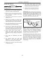
HOOD LATCH
As viewed from the front of tractor:
1. To raise the food, pull the latch release ①
to the left and move safety catch ② upward.
A gas spring ③ assists in lifting the hood,
and holding it in its raised position.
2. To lower the hood, push downward against
the resistance of the gas spring, until the
hood engages the latch mechanism.
①
②
NOTE: Keep the latch mechanism free of dirt
and debris, so the latch will operate properly.
③
THREE-POINT LINKAGE
The tractor's three-point linkage is used to attach
three-point mounted equipment which is usually
PTO-operated, such as rotary mowers, tillers,
flail mowers, snowblowers, etc. The three linkage
points are the two lower lift arms and the top link.
The height of the RH lift arm and the top link can
also be adjusted, by loosening the jam nut ①
turning the adjustment turnbuckle ② and
re-tightening the jam nut.
①
②
2-17
SECTION 2 – OPERATION
The standard three-point linkage has easilyadjustable sway bars ③ to control the lateral
movement of the lift arms.
NOTE: Cycle the three point linkage through the
entire travel and check for any interference with
rear tires. If interference is present, adjust sway
bars as needed.
③
TOOL BOX
A tool box ① with a latching lid, is located
behind the seat and between the ROPS uprights.
①
DRINK HOLDER
A drink holder ② is attached to the left fender,
for the operator's drink storage convenience.
②
2-18
SECTION 2 – OPERATION
TRACTOR HYDRAULICS
HYDRAULIC POWER LIFT (H.P.L.) (3 PT)
The H.P.L. lever ① is located on the RH control
pod, inboard of the PTO clutch lever. This lever
controls the position of the two lift arms.
Operating the hydraulic control lever actuates the
hydraulic lift arms, which controls the elevation of
3-point hitch mounted implement.
To lower implement, move the hydraulic control
lever forward.
To raise implement, move the hydraulic control
lever rearward.
The hydraulic control lever is automatically
returned to the neutral position ONLY when the
lift arms have reached the upper position.
IMPORTANT: While raising or lowering the lift
arms the hydraulic control lever must be
manually placed in the neutral position to stop
the travel of the lift arms.
WARNING
Make sure the area is clear of people before
lowering equipment.
2-19
①
SECTION 2 – OPERATION
DROP RATE VALVE
The drop rate valve provides an adjustment to
regulate the flow of oil from the lift cylinder. This
allows the operator to decrease or increase the
rate of drop of the lower links. On this tractor
model, the drop rate control knob ① is located
directly below the front of the seat.
Turn the flow control valve "IN" (clockwise) to
decrease the rate of drop. Turn the valve "OUT"
(counterclockwise) to increase the rate of drop.
The flow control valve must be opened before
the hydraulic lift control will lower. If the valve is
turned all the way "IN" (clockwise), the lower
links can be raised to maximum height, but
cannot be lowered.
REAR REMOTE CONTROL VALVE
(OPTIONAL)
Your SHIBAURA tractor can be equipped with
one auxiliary valve. If so equipped, the control
lever is located on the RH control pod ①
inboard of the hitch control lever.
To operate the single-spool valve, pull the control
lever rearward to extend the cylinder. Push the
control lever forward to retract the cylinder.
Release the control lever to stop the cylinder in
any position before it is fully extended. The lever
automatically returns to neutral.
The auxiliary valve can be fitted with either rear
3/8" quick couplers ①.
2-20
①
SECTION 2 – OPERATION
DRIVING THE TRACTOR
●
Any towed vehicle whose total weight
exceeds that of the towing tractor must be
equipped with brakes for safe operation.
●
Always check overhead clearance,
especially when transporting the tractor.
WARNING
Observe the following precautions when
driving the tractor.
●
Watch where you are going—especially at
row ends, on roads, and around trees.
● Keep the tractor in gear when going down hill.
Use a low gear to maintain control with
minimum braking.
●
If the tractor is stuck, back out to prevent
upsetting the unit.
●
Always use the drawbar for pull-type work.
Do not pull from any other part of the tractor,
especially ROPS since it may tip backward.
●
Keep the lights adjusted so they do not blind
the operator of an oncoming vehicle.
●
Press the H.S.T. pedal slowly when driving
out of a ditch, gully, or up a steep hillside.
Immediately release the forward speed pedal
if the front wheels should rise off the ground.
●
Reduce speed before turning quickly or
applying the brakes. Brake both wheels
simultaneously when making an emergency
stop.
●
Never apply the differential lock when
turning.
●
Use extreme caution and avoid hard
applications of the tractor brakes when
pulling heavy towed loads at road speeds.
●
Always sit in the driver's seat while starting
or driving the tractor.
IMPORTANT: When transporting on the highway,
it is recommended that a safety chain with tensile
strength equal to the gross weight of the
implement be connected between the tractor and
the towed implement. This will control the
implement in the event the hitch pin is lost.
NOTE: Attaching hardware will need to be
procured locally. Check implement assembly or
operators manual for attaching hardware
specifications, such as bolt size and grade, chain
strength, washers, lock-washer, nuts, etc.
After attaching the safety chain, make a trial run
by driving the tractor to the right and to the left
for a short distance to check the safety chain
adjustment. If necessary, readjust to eliminate
tight or loose chain. Safety chains and suitable
hardware are available from your SHIBAURA
Tractor Dealer
2-21
SECTION 2 – OPERATION
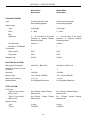
WHEEL TREAD SETTINGS
NOTE: Tread settings are measured from center of tire to center of tire.
Front Wheel Settings
Tire Type
Tractor Model
Setting
Note
BAR
18 x 8.50 – 8
Front-Wheel Drive
940 mm
Not Adjustable
18 x 8.50 - 8
Front-Wheel Drive
940 mm
Not Adjustable
Front-Wheel Drive
910 mm
Not Adjustable
Turf
Agricultural
4.00 – 9
IMPORTANT: Never attempt to widen the tread setting by reversing the front wheels on a front-wheel
drive system.
NOTE: Torque front wheel bolts to 88 N · m .
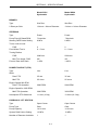
Rear Wheel Settings
Tire Type
Tractor Model
Setting
Note
BAR
26 x 12.00 – 12
Front-Wheel Drive
870 mm
Not adjustable
Turf
26 x 12.00 – 12
Front-Wheel Drive
870 mm
Not Adjustable
Agricultural
7 – 14
Front-Wheel Drive
910 mm
Not Adjustable
Note: Torque rear wheel bolts to 122 N · m .
2-22
TRACTOR WEIGHTING
For sufficient traction and maximum performance
in heavy draft operations, and to counterbalance
rear-mounted equipment, weight should be
added to tractor in the form of liquid ballast, cast
iron weights or a combination of both. Only
enough weight should be added to provide good
traction and stability. Adding more weight than is
needed results unnecessary soil compaction,
increased rolling resistance, and higher fuel
consumption.
When a mounted implement is raised to the
transport position, the front wheel reaction
should be at least 20% of tractor weight.
NOTE: When adding weight to the tractor, tire
pressures may need to be increased. Refer to
the Tire Inflation Pressure chart found in this
manual.
When using front-mounted equipment, add
weight to the rear axle of the tractor to maintain
good traction and stability. Front-mounted
equipment varies in weight. Refer to equipment
manual for ballasting.
WEIGHTING FOR STABILITY
Front end ballast may be required for stability
and steering control when weight is transferred
from the front wheels to the rear wheels as an
implement is raised by the tractor three-point
hitch.
Add additional front end ballast as required for
stability during operation and transport. Tractor
front end ballast may not always maintain
satisfactory stability if the tractor is operated at
high speed on rough terrain. Reduce tractor
speed and exercise caution under these
conditions.
WEIGHTING LIMITATIONS
The weighting limitations that follow are
limitations only. They do not imply that the tractor
should be weighted to attain the weights given.
Use only enough weight to obtain good
performance.
As a general guide:
Ballast the tractor (less implement) so that
approximately one-third of the tractor weight is
on the front wheels. For optimum traction,
tractors equipped with front-wheel drive should
be ballasted so that 40-45% of machine weight is
on the front wheels.
2-23
SECTION 2 – OPERATION
CAST IRON WEIGHTS (OPTIONAL)
Cast iron weights are available as accessories
from your SHIBAURA Dealer. Weights can be
mounted on the front end of the tractor and on
the rearmost wheels.
NOTE: Front weight bracket 370220230,
372111070 is required to install front weights.
Front End Weights
Tire Type
Agricultural and Turf
Weight(s)
Maximum of (2) weights
per tractor @ 30 kg each
60 kg total
2-24
SECTION 2 – OPERATION
LIQUID BALLAST (OPTIONAL)
It is a common practice to add weight to the
tractor by filling rear tires with liquid. A calcium
chloride (CaCl2) and water solution is
recommended due to its low freezing point and
greater density (weight per gallon) than pure
water.
Never exceed the total recommended weight for
the tractor. Because special equipment is
required to fill the tires, consult your SHIBAURA
Dealer.
Tires should never be filled beyond 75%. At 75%
full, the liquid will come to the valve stem when
the valve stem is at its highest point at the top of
the wheel.
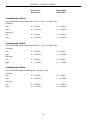
TIRE PRESSURE
Tire pressure must be considered when adding
weights, implements, or attachments to the
tractor or damage to the tractor may occur.
The chart below outlines tire inflation pressures.
FRONT TIRE INFLATION PRESSURES
Tire Type
Tire Size
Inflation Pressure
BAR:
18 x 8.50 – 8
60 – 140 kPa
18 x 8.50 – 8
60 – 140 kPa
4.00 – 9
120 – 240 kPa
Turf:
AG:
REAR TIRE INFLATION PRESSURES
Tire Type
Tire Size
Inflation Pressure
BAR:
26 x 12.00 – 12
80 – 140 kPa
26 x 12.00 – 12
80 – 140 kPa
7 – 14
120 – 180 kPa
Turf:
AG:
NOTE: Do not underinflate or overinflate tires. Do not exceed maximum inflation pressure listed.
2-25
SECTION 2 – OPERATION
2-26
SECTION 3
LUBRICATION AND MAINTENANCE
Adequate lubrication and maintenance on a
regular schedule is vital to maintaining your
equipment. To ensure long service and efficient
operation, follow he lubrication and maintenance
schedules outlined in this manual. The use of
proper fuels, oils, grease and filters, as well as
keeping the systems clean, will also extend
machine and component life.
CAUTION
Observe these safety precautions before
performing lubrication and maintenance.
1. Shut off engine.
2. Disengage all drives.
3. Lower all attachments to the ground or
raise and engage all locks
4. Close all shields opened and reinstall any
shields removed for lubrication and
maintenance proposes.
IMPORTANT: Always use genuine SHIBAURA
replacement parts, oils and filters to ensure
proper operation, filtration of engine and
hydraulic systems. See your SHIBAURA dealer
for additional oil quantities.
CAUTION
Some illustrations in this manual show
shields opened or removed to show areas
being serviced. Replace all shields before
operating this machine.
GENERAL INFORMATION
Regular lubrication is the best insurance against
delays and repairs. Proper lubrication will extend
machine life. Refer to the following charts for
lubricants and service intervals.
Always clean the area around dipsticks, fill caps,
and check plugs when checking fluid levels.
Failure to clean these areas may allow
contamination to enter the system. Drain, flush
and refill the system anytime you suspect it is
contaminated.
IMPORTANT: Failure to complete the required
maintenance at the recommended intervals can
cause unnecessary downtime.
The intervals listed in the Lubrication Chart are
guidelines to be used when operating in normal
conditions. Adjust the intervals for operating in
adverse environmental and working conditions.
The intervals should be shortened for sandy,
dusty and extremely hot operating conditions.
Grease Fittings
Wipe dirt from fittings before greasing.
Pump fresh grease into fitting to adequately
lubricate the component and force out any
contamination from the grease passage.
Wipe off excess grease.
Use a grease gun containing clean high grade of
multipurpose grease.
Chains
Stop all drives before lubricating chains.
3-1
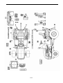
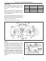
SECTION 3 – LUBRICATION AND MAINTENANCE
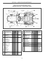
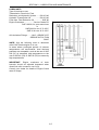
LUBRICATION AND MAINTENANCE CHART
SHIBAURA SX21/SX24 – FRONT-WHEEL DRIVE
21
⑧
② 22
⑰⑱⑲⑳
23
⑧ 21
⑤
①⑦⑩
④
⑫③
⑯
⑨
⑬⑭
⑥
First
50 Hours
×
Every
50 Hours
R
A
I
22 Fuel Injector
23 Valve Clearance
N
×
×
×
×
×
×
Every
100 Hours
×
3-2
SERVICE
INTERVALS
Every
200 Hours
×
×
×
Transmission Oil
Hydraulic Filter
H.S.T. Filter
Front Axle Oil
Final Reduction
Gear Cases Oil
24 Primary Fuel Filter
×
×
×
×
D
×
×
×
×
×
4
5
6
13
14
×
ADJUST
×
×
×
Brake
Fuel Filter Element
Fan Belt
Wheel Bolt Torque
Steering Free Play
LUBE
1, 7 Engine Oil & Filter
2 Air Cleaner
Element
10 Secondary Fuel Filter
20
10
12
21
Every
10 Hours
or Daily
LUBRICATION &
MAINTENANCE ITEMS
CHANGE
16
17
18
19
NO.
CLEAN
Tires
Battery
Secondary Fuel Filter
Fan Belt
Front Axle Oil Level
Final Reduction
Gear Cases Oil
Level
Lubrication
Fittings:
3-Point Linkage
Brake Pedal
Pedal Shaft
H.S.T. Pedal Pivot
×
×
×
×
SERVICE
INTERVALS
CHECK
8
9
10
12
13
14
ADJUST
Hydraulic Filter
H.S.T. Filter
Engine Oil & Filter
Tire Pressure
Fuel Filter Element
Wheel Bolt Torque
All Fluid Levels
CHANGE
5
6
1, 7
8
10
26
-
LUBE
Engine Oil Level
Air Cleaner
Radiator Coolant
Transmission Oil Level
CLEAN
1
2
3
4
LUBRICATION &
MAINTENANCE ITEMS
CHECK
NO.
24
21
21
×
×
×
×
×
×
Every
300 Hours
×
×
×
×
×
Every
600 Hours
2
3
Air Cleaner
Radiator Coolant
×
×
Seasonal
2
Safety Air Filter Element
×
Every 3
Primary
Element
Change or
Every 1000
Hours,
Whichever
Comes First
rd
SECTION 3 – LUBRICATION AND MAINTENANCE
LUBRICATION FITTINGS
NOTE: After every 50 hours of normal operation,
apply a good quality grease to the lubrication
points listed below (refer to the Recommended
Lubricants chart). When operating under
extremely dirty conditions, lubricate more
frequently than every 50 hours.
•
Steering Linkage
•
Front Axle Pivot
•
Power Steering Cylinder
•
Pedal Shaft—Clutch & Brake Pedals
•
3-Point Linkage
1. Wipe away all old grease and dirt from the
lubrication fittings to prevent dirt or foreign
material from entering as new grease is
applied.
2. Use a high pressure grease gun to force in
the new grease. Apply pressure until clean
grease oozes from each lubrication point.
3. Wipe away any excess grease.
DIESEL FUEL
• Use clean, quality No. 1 -D or No. 2-D fuel
(ASTM D975).
Use No. 1-D fuel if the ambient temperature
is expected to be lower than 4°C or if the
tractor is to be used at an altitude exceeding
1524 m.
•
Use No. 1-D diesel fuel with a pour point of
at least -12°C below the expected ambient
temperature to prevent fuel flow problems in
cold weather.
•
Keep dirt from entering the fuel tank.
•
Sulfur content of the fuel should be no more
than 0.5%.
•
Sediment and water content should not
exceed 0.05%.
Minimum cetane number is 40. Low
temperature or high altitude operation may
require use of fuel with a higher cetane
number.
•
Use properly mixed winter fuel when
temperatures are extremely cold. In most
areas, diesel fuel is properly blended for
summer and winter grades as ambient
temperatures change. In winter, use winter
grade diesel fuel only. Otherwise, the fuel
may jell and block the fuel system.
Fuel Usage Safety
• UNDER NO CIRCUMSTANCES should
gasoline, alcohol, or gasohol be added to
diesel fuel. These combinations can create
an increased fire or explosive hazard.
To lubricate these points:
•
•
3-3
•
Never remove the fuel cap or refuel the
tractor while the engine is running.
•
Never smoke while refueling or anywhere
near fuel.
•
When filling the tank, maintain control of the
nozzle.
•
Do not fill the fuel tank to capacity. Allow
room for expansion.
•
Wipe up spills immediately.
•
Always tighten the fuel cap securely.
•
If the original fuel tank cap is lost, always
replace it with a SHIBAURA approved cap. A
"will-fit" cap may not be safe.
•
Keep equipment properly maintained.
•
Do not drive equipment near open fires.
•
Never use gasoline for cleaning parts.
SECTION 3 – LUBRICATION AND MAINTENANCE
WARNING
Fuel oil in the injection system is under high
pressure and can penetrate the skin.
Unqualified persons should not remove or
attempt to adjust a pump injector, nozzle, or
any part of the fuel injection system.
•
•
Do not use your hand to check for leaks.
Use a piece of cardboard or paper to
search for leaks.
If any fluid is injected into the skin, obtain
medical
attention
immediately
or
gangrene may result.
Failure to follow these instructions can result
in serious injury.
Refueling the Tractor
The fuel tank filler cap ① is located on top of the
RH fender, to the rear of the control pod. Before
removing the cap, wipe all dust and dirt from
around the cap to prevent debris from falling into
the tank during filling.
Use an approved container and check the inside
of the container periodically for cleanliness. The
tractor fuel tank capacity is 29.5 L.
①
NOTE: The fuel cap is a vented-type. Use only
an approved SHIBAURA replacement cap to
prevent fuel system-related problems.
If there is no filter on the storage tank or fuel
container, filter the fuel through a 100-mesh or
finer screen when filling the tractor fuel tank.
Keep the tractor tank as full as possible (without
overfilling) to minimize condensation.
NOTE: It is a good practice to fill the fuel tank at
the end of each day, as this will reduce overnight
condensation.
3-4
SECTION 3 – LUBRICATION AND MAINTENANCE
LUBRICANTS
Type of lubricant to use,
Transmission, Rear Axle, Final
Reduction, and Hydraulic System······· ISO VG 46
Hydraulic Transmission Oil ················· ISO VG 46
Front Axle, Final Reduction Oil ················ SAE 80
Engine Crankcase··················· Service Grade CD
SAE 10W30, for year around use
or
SAE 20W for use -5°C–25°C
SAE 30 for use 10°C–35°C
All Lubrication Fittings··········NLG 1 GRADE 2 EP
GREASE WITH LTIUM
SOAP
NOTE: Use the following chart to determine
which SAE Grade engine oil to use:
In areas where prolonged periods of extreme
temperatures are encountered, local lubricant
practices are acceptable, such as the use of SAE
5W (CC) in extremely cold temperatures or the
use of SAE 40 (CD) or SAE 50 (CD) in extremely
high temperatures.
IMPORTANT: Engine crankcase oil drain
intervals should be adjusted downward when
diesel fuel sulfur content is over 0.5%.
Consult your dealer for details of Engine Crank
case Oil usage.
3-5
SECTION 3 – LUBRICATION AND MAINTENANCE
FUEL AND LUBRICANT SERVICE PROCEDURES
ENGINE
Check the engine oil level
NOTE: Check the engine oil level daily, or after
every 10 hours of operation.
1. After the engine has been stopped for a
period of time, and with the tractor standing
level, check the oil level using the dipstick.
2. If the oil level is low, remove the filler cap ②
and add oil through the filler hole. Add
enough oil so that the level registers
between the two marks on the dipstick. Do
not overfill.
②
Changing the Engine Oil
NOTE: Change the engine oil and filter after the
first 50 hours of operation, then every 100 hours
thereafter. If the tractor is operated for extended
periods of time at maximum rated power and
speed, or under other types of continuous,
severe operating conditions, the engine oil and
filter should be changed at 70-hour Intervals
following the initial oil change.
To change the engine oil:
1. Place a suitable container beneath the drain
opening to catch the used oil. With the
tractor engine off but at normal operating
temperature, remove the drain plug ③ .
Reinstall the plug after all of the oil has been
drained.
CAUTION
Engine oil could be hot, use caution during
draining.
3-6
SECTION 3 – LUBRICATION AND MAINTENANCE
2. Place a suitable container below the oil filter
① to catch the used oil and unscrew the oil
filter. Discard the used oil and filter.
3. Coat the gasket on the new filter with a thin
film of new oil. Screw the filter into place until
the gasket contacts its mating surface, then
turn the filter approximately three-quarters of
a turn BY HAND. Do NOT overtighten.
4. Add the proper type and amount of new oil,
then start the engine and check the filter for
leaks. The crankcase capacity (with filter) on
these tractor models is 4.0L.
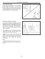
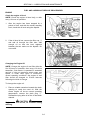
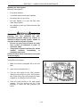
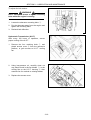
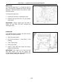
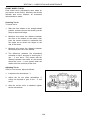
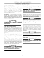
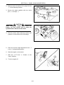
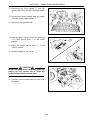
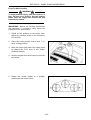
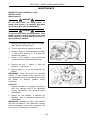
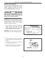
PRIMARY FUEL FILTER
NOTE: Primary fuel filter should be replaced
every 300 hours of operation.
The primary fuel filter ① is installed in the fuel
line between the fuel tank and the electric fuel
pump. Location left rear of tractor, (left rear tire
removed for clarity).
To replace filter:
1. Remove left rear tire assembly and support
axle with jack stand.
2. Drain the fuel tank or pinch the fuel hose to
prevent fuel leakage.
3. Remove filter mounting clamp ② from filter.
4. Loosen clamps ③ from fuel line and remove
fuel filter from fuel hose.
5. Install new fuel filter, pay attention to
directional arrow on filter, arrow points in
direction of fuel flow, from tank to engine.
6. Install line clamps ③ and mounting clamp
② to filter.
7. Check for any leakage, place key switch in
the "ON" position for a several seconds to
bleed any air out of fuel system.
3-7
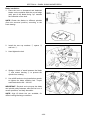
SECTION 3 – LUBRICATION AND MAINTENANCE
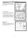
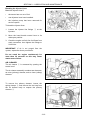
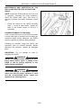
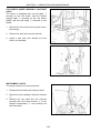
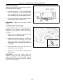
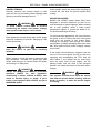
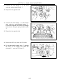
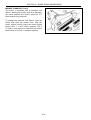
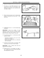
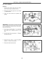
SECONDARY FUEL FILTER
Draining the Fuel Filter
NOTE: The fuel filter should be drained after
every 100 hours of operation.
1. Make sure there is adequate fuel in the fuel
tank and close the fuel shutoff valve ① (the
handle should be pointing to the "C" position).
Remove the fuel sediment bowl ②.
2. Open the fuel shutoff valve until all water has
been removed and only fuel flows from the
filter base.
3. Install the fuel sediment bowl and bleed the
system as outlined in "Bleeding the Fuel
System."
NOTE: Valve is shown in open position.
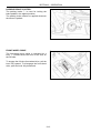
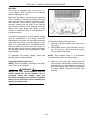
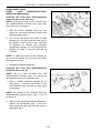
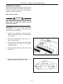
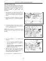
Changing the Fuel Filter
NOTE: Change the diesel fuel filter after the first
50 hours of operation, then following every 200
operating hours thereafter.
1. Close the shutoff valve (the handle should be
pointing to the "C" position).
2. Remove the sediment bowl by rotating the
retaining nut ①.
3. Open the fuel shutoff valve ② to drain any
remaining water from the tank.
4. Discard the old element ③ and install a new
element.
5. Inspect the O rings ④ and ⑤ and replace if
necessary.
6. Install and securely tighten the sediment
bowl.
7. Open the fuel shutoff valve (the handle
should be pointing to the "O" position) ② so
fuel will flow to the filter.
8. Bleed the fuel filter and injection pump as
described next in "Bleeding the Fuel
System."
3-8
SECTION 3 – LUBRICATION AND MAINTENANCE
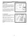
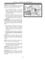
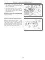
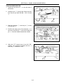
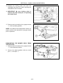
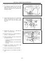
Bleeding the Fuel System
Bleed the fuel system if:
•
it has been drained.
•
a new filter element has been installed.
•
the tractor has run out of fuel.
•
the lines leading to or from the filter have
been disconnected.
•
the injection pump has been removed and
reinstalled.
WARNING
Fuel oil in the injection system is under high
pressure and can penetrate the skin.
Unqualified persons should not remove or
attempt to adjust a pump injector, nozzle, or
any part of the fuel injection system.
• Do not use your hand to check for leaks
Use a piece of cardboard or paper to
search for leaks.
• If any fluid is injected into the skin, obtain
medical
attention
immediately
or
gangrene may result.
Failure to follow these instructions can result
in serious injury.
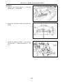
To bleed the fuel system:
1. Make sure there is adequate fuel in the fuel
tank.
2. Open the fuel shutoff valve ①.
3. Turn the key switch to the "ON" position.
When the key switch is in the "ON" position,
the electric fuel pump will operate and allow
trapped air to escape from the fuel filter.
4. Push the hand throttle to the high speed
position. Turn the engine over for a few
seconds to bleed the high pressure fuel
tubes.
3-9
SECTION 3 – LUBRICATION AND MAINTENANCE
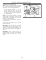
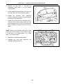
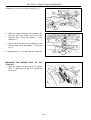
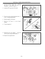
Bleeding the Injector Lines
Bleed the injector lines if:
•
the tractor has run out of fuel.
•
new injectors have been installed.
•
the injection pump has been removed for
service repairs.
To bleed the injector lines:
1. Loosen the injector line fittings ① at the
injectors.
2. Move the hand throttle control lever to its
wide open position.
3. Crank the engine until air-free fuel flows from
each connection, then tighten the fittings to
24-29 N·m.
IMPORTANT: If air is not purged from the
system, repeat the above procedures.
Do not crank the engine continuously for
more than 30 seconds as this may cause
starter motor failure.
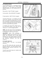
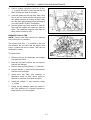
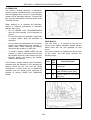
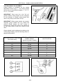
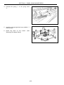
AIR CLEANER
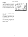
The air cleaner ① is accessed by opening the
tractor hood.
The air cleaner assembly contains two elements:
an outer (primary) element, and an inner (safety)
element.
To remove the primary element, loosen the
spring clamps ② and remove the end cap from
the air cleaner body to expose the primary
element ③.
3-10
SECTION 3 – LUBRICATION AND MAINTENANCE
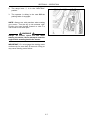
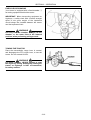
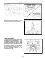
Air Cleaner Primary Element
NOTE: Clean the primary element after every
100 hours of service. Extremely dusty conditions
may require more frequent service intervals.
1. Pull the primary element ③ from the
canister. Clean any loose dirt from the
canister, and inspect the end of the canister
for dirt which may prevent the new element
from seating properly.
2. Clean the primary element using low
pressure air (30 PSI or less). Blow dust from
the inside toward the outside of the element
(i.e., opposite to normal air flow through the
element).
IMPORTANT: Be careful not to rupture the filter
element. Maintain a safe distance between the
air nozzle and the filter element when directing
air up and down the clean air side of the element
pleats.
3. After cleaning the element, check the inner
diameter seals for damage. If damage is
present, replace the primary element.
Change the element after six cleanings or
once a year.
4. Reinstall the primary element by inserting it
into the canister and pushing on the end of
the element until it is seated against the
canister.
NOTE: Place a light inside the element to check
for paper leaks or for bonding of the paper to the
end plate. If any leaks are found, replace the
element.
NOTE: If element is not inserted far enough into
canister, the end cap cannot be installed.
5. Place the end cap onto the canister body
and attach spring clamps. Make sure the end
cap is locked in place and not loose.
IMPORTANT: Never tap the element with hard
objects or against a hard surface. This may dent
or break the element end cap seals.
IMPORTANT: Failure to obtain a good seal
between elements and the canister may cause
major engine damage, by allowing dirt to enter
the engine.
3-11
SECTION 3 – LUBRICATION AND MAINTENANCE
Air Cleaner Inner Safety Element
NOTE: Clean the primary element after every
100 hours of service. Extremely dusty conditions
may require more frequent service intervals.
1. Pull the primary element ① from the
canister. Clean any loose dirt from the
canister, and inspect the end of the canister
for dirt which may prevent the new element
from seating properly.
NOTE: Conduct a visual inspection of the inner
safety element ② by placing a light inside the
element. Little or no light will shine through the
element if it is partially clogged.
To remove the inner safety element, pull it out of
the canister body.
To install the new element, push it into the
canister until seated.
IMPORTANT: Clean any dirt from the canister
before installing the inner safety element. Check
element inner diameter seals for damage and
replace the safety element if seal damage is
present.
IMPORTANT: Failure to obtain a good seal
between the filter and canister may cause major
engine damage, by allowing dirt to enter the
engine.
3-12
①
②
SECTION 3 – LUBRICATION AND MAINTENANCE
TRANSMISSION, REAR AXLE, AND
HYDRAULIC SYSTEM
Checking the Transmission, Rear Axle, and
Hydraulic System Oil Level
NOTE: Check the transmission, rear axle, and
hydraulic system oil level after every 50 hours of
operation.
1. With the engine off and the tractor standing
level, check the oil level using the dipstick ①.
The dipstick is located on the rear of the
transmission housing, on the RH side, above
the rear PTO guard. The oil is at the correct
level when it reads between the two marks
on the dipstick, after fully inserting dipstick.
2. If the level is low, remove the filler plug ②
and ISO VG 46 hydraulic oil through the filler
hole. The filler plug is located on the upper
rear of the transmission housing, above the
hydraulic lift rocker. Do not fill above the
dipstick 'full' mark.
3. Reinstall the filler plug and dipstick.
3-13
SECTION 3 – LUBRICATION AND MAINTENANCE
Changing the Transmission, Rear Axle, and
Hydraulic System Oil
NOTE: Change the transmission, rear axle, and
hydraulic system oil after every 300 hours of
operation.
NOTE: During cold weather operation, tractor
hydraulic oil can be changed to ISO VG 46 oil is
a multiviscosity oil which has improved flow
characteristics in low temperatures and can be
used year round.
1. Place a suitable container beneath the
transmission and rear axle drain plug to
catch the used oil. (Note that the combined
reservoir holds 13L of oil.) With the oil at
normal operating temperature, drain the
system by removing the transmission and
rear axle drain plug ① and the filler plug ②.
Reinstall the drain plug after all of the oil has
drained out. Discard the used oil properly.
2. Add ISO VG 46 hydraulic oil at the filler hole,
②. The transmission is filled to the correct
level when the oil registers between the two
marks on the dipstick ③. Do NOT fill above
the dipstick full mark. Capacity for the H.S.T.
reservoir is 13L.
3. Reinstall the dipstick and filler plug.
IMPORTANT: There is a common sump for the
transmission, rear axle, and hydraulic system.
Therefore, extra care should be taken to keep
the oil clean.
3-14
SECTION 3 – LUBRICATION AND MAINTENANCE
HYDRAULIC SYSTEM OIL FILTER
NOTE: Replace the hydraulic system oil filter ①
after the first 50 hours of operation, and then
following every 300 hours of operation thereafter.
The hydraulic system uses a spin-on type oil filter,
located on the RH side of the front of the
transmission, below and in front of the rear axle.
To replace the filter:
1. Place a suitable container beneath the filter,
to collect any oil that drains out during the
filter change.
NOTE: Removing the hydraulic oil filter will drain
most of hydraulic reservoir.
Remove transmission drain plug ②
removing hydraulic filter.
before
2. Unscrew the used oil filter ① and discard.
3. Coat the gasket on the new filter with a thin
film of clean oil. Screw the filter into place
until the gasket contacts the sealing surface,
then
tighten
the
filter
BY
HAND
approximately three-quarters of a turn. Do
NOT overtighten.
4. Start the engine and check the filter for
leaks.
5. Stop the engine and check the hydraulic
system oil level. Add oil if necessary.
HYDROSTATIC TRANSMISSION (H.S.T.)
SYSTEM OIL FILTER
NOTE: Change the H. S. T. system oil filter ②
after the first 50 hours of operation, and then
following every 300 hours of operation thereafter.
The H.S.T. system oil filter is located just below
the main platform deck in front of the driver's
seat. The filter is mounted inside the LH side of
the chassis frame, facing rearward, and can be
accessed from below the tractor. It is helpful to
remove the plastic access cover in the main
platform deck immediately in front of the driver's
seat, to provide a clear view of the filter during
changeover.
To change the H.S.T. system oil filter ② follow
the procedures found above for changing the
hydraulic system oil filter.
3-15
SECTION 3 – LUBRICATION AND MAINTENANCE
GENERAL MAINTENANCE
COOLING SYSTEM
The tractor engine must operate at the correct
temperature to obtain maximum efficiency and
service life. This is dependent on the cooling
system.
Always fill the system with a 50/50 solution of
permanent antifreeze and clear water.
①
Checking the Coolant Level
NOTE: Check the coolant level daily or after
every 10 hours of operation. The engine should
be cold when coolant level is checked.
Open the hood, and check the coolant recovery
reservoir, mounted to the LH side of the radiator
frame. The fluid level should be between the 'low'
and 'full' marks on the reservoir ①.
If the coolant recovery reservoir is empty,
carefully remove the radiator cap ② and add the
antifreeze/ water solution directly into the radiator
until the radiator is full. Then cap the radiator and
add the solution to the recovery reservoir to bring
the level up to the 'full' mark.
WARNING
The cooling system operates under pressure
controlled by the radiator cap. It is dangerous
to remove the cap while the system is hot.
Always cover the cap with a thick cloth and
turn it slowly counterclockwise to the first
stop. Allow all pressure to escape before
removing the cap completely.
If the coolant level is below the low mark on the
reservoir, add a 50/50 solution of water and
antifreeze to the coolant recovery reservoir
bringing the level to the full mark.
Be sure that the radiator fins are clear of chaff
and dirt to allow free air movement.
3-16
②
SECTION 3 – LUBRICATION AND MAINTENANCE
Draining and Flushing the Cooling System
NOTE: Drain and flush the radiator and engine
block every 12 months. Refill with a 50/50
solution of permanent antifreeze and clear water.
To drain the cooling system:
1. Place a suitable receptacle to catch the used
coolant. (The coolant system capacity is
3.5L). Re move the radiator cap and open
the drain valve ① on the bottom center of
the radiator to drain the coolant from the
radiator and engine block.
2. After the coolant has drained, place a water
hose in the radiator filler neck and run water
through the system. After water begins
flowing out of the drain valve, start the
engine. Run the engine until the water
flowing from the drain valve is free of
discoloration and sediment, then stop the
engine and remove the hose. Allow all water
to drain from the system through the drain
valve.
3. Close the drain valve and slowly refill the
system with a 50/50 solution of permanent
antifreeze and clear water. Fill the radiator
until the coolant level is approximately 3.8 5 cm below the bottom of the filler neck. Do
not fill beyond this level.
4. Clean the radiator cap and cap seal and
install the cap.
5. Fill the coolant recovery reservoir until the
fluid level is between the "full" and "low"
marks on the reservoir.
6. Clean the radiator front screen ②.
7. Run the engine until normal operating
temperature is reached, then stop the engine.
Recheck the coolant level when the engine
has cooled, and add more coolant as
necessary.
IMPORTANT: NEVER run the engine when the
cooling system is empty. Do NOT add cold water
or cold antifreeze solution if the engine is hot.
3-17
SECTION 3 – LUBRICATION AND MAINTENANCE
Thermostat
The thermostat is a heat-sensitive valve located
in the coolant outlet connection in the front of the
cylinder head.
When the engine is cold, the thermostat shuts off
the flow of coolant to the radiator, allowing for
rapid engine warm-up. A recirculating bypass
allows coolant to circulate inside the engine
whenever the thermostat shuts off flow to the
radiator.
IMPORTANT: Do not attempt to improve
cooling by removing the thermostat. This will
cause the engine to run below normal
working temperatures, resulting in excessive
engine wear.
To install a new thermostat ① position it in the
recess of the water outlet connection so that the
heat element (spring end) is in the cylinder head
of the engine.
Fan Belt
NOTE: Check the condition of the fan beIt after
every 50 hours of operation. Check fan belt
tension after every 200 hours of operation.
A belt-driven fan located at the front of the
engine draws air through the fins of the radiator
to lower the temperature of the radiator coolant.
When 5 kg of thumb pressure is applied to the
belt midway between the belt pulleys, a correctly
tightened belt will deflect 5 - 10 mm.
If the fan belt is slipping, fan efficiency is lowered,
resulting in the engine running too hot. If the belt
is too tight, the life of the alternator bearing will
be shortened. If the fan belt shows signs of
cracking or fraying, install a new belt.
3-18
SECTION 3 – LUBRICATION AND MAINTENANCE
To adjust fan belt tension:
WARNING
Never attempt to loosen or tighten mounting
bolts while the engine is running.
1. Loosen the alternator mounting bolts ①.
2. Pry the alternator away from the engine and
tighten the mounting bolts.
3. Recheck belt deflection.
Hydrostatic Transmission (H.S.T.)
After every 100 hours of operation, ensure
proper cooling of the H.S.T.:
1. Remove the four retaining bolts ① and
plastic access cover ② from the operator's
platform, to gain access to H.S.T. cooling
fan.
②
①
2. Using low-pressure air, carefully clean out
any debris found in the fan blades ③ or the
cooling fins on the H.S.T. housing ④. Also
examine fan for cracked or missing blades.
3. Replace the access cover.
3-19
SECTION 3 – LUBRICATION AND MAINTENANCE
MAINTENANCE AND INSPECTION OF THE
ROLLOVER PROTECTIVE STRUCTURE
(POPS)
NOTE: Inspect the ROPS after the first 20 hours
of operation. Following the initial inspection,
check the ROPS after every 500 hours of
operation or every six months, whichever comes
first.
1. Check the torque of the ROPS mounting
bolts ① on top of each fender. Tighten the
bolts to the correct torque of 50 N·m if
necessary.
POSSIBLE DAMAGE TO THE ROPS
If the unit has rolled over or the ROPS has been
in some other type of accident (such as hitting an
overhead object during transport), the ROPS
must be replaced to retain the best protection.
Following an accident, check the ROPS, the
operator's seat for possible damage. Before
operating the machine, replace all damaged
parts.
IMPORTANT: Do not attempt to weld or
straighten the ROPS.
WARNING
Always pull from the tractor drawbar pin hole.
Never attach chains, ropes, or cables to the
ROPS or cab for pulling purposes or the
tractor will tip backwards.
WARNING
If the ROPS or cab is removed or replaced,
make sure that the proper hardware is used
and the recommended torque values are
applied to the attaching bolts.
3-20
①
①
SECTION 3 – LUBRICATION AND MAINTENANCE
BATTERY
The tractor is equipped with a BCI group 51,
12-volt battery, with a minimum cold cranking
ability of 450 amps at -18ºC.
Make sure the battery connections are tight and
free of corrosion. A solution of backing soda and
water may be used to clean the outside surface
and terminals of the battery when necessary.
However, ensure that the none of the solution
gets inside the battery. After cleaning, rinse the
battery with clean water, then apply a small
amount of petroleum jelly to the terminals to
prevent corrosion.
In freezing temperatures, a good battery charge
must be maintained. If the battery becomes
discharged or run down, the electrolyte becomes
weak and may freeze, causing damage to the
case. If you must add water, use distilled water.
Add the water just before using the tractor so
that the water will mix with the electrolyte during
the charging process, thus preventing the water
from freezing.
To check the battery electrolyte level:
1. Clean the top of the battery, then remove the
vent plugs.
2. Add distilled water if the electrolyte level is
low. The level is correct when the liquid is
6.35 mm above the plates.
To determine the battery charge, check the
specific gravity of the electrolyte.
NOTE: Keep distilled water in a nonmetallic
container that is clean and well-covered.
Checking the Electrolyte Level
NOTE: Check the battery electrolyte level after
every 50 hours of operation.
3. Install the vent plug after making sure the
vent holes are not blocked. At below freezing
temperatures, run the engine for a period of
time after adding water, allowing the battery
to charge, which prevents the water from
freezing.
WARNING
Always check the electrolyte level with the
tractor engine off, as an explosive gas is
produced inside the battery when the
alternator is charging. Do not use an exposed
flame and do not smoke when checking the
battery electrolyte level.
3-21
SECTION 3 – LUBRICATION AND MAINTENANCE
ALTERNATOR
The tractor's 40-amp alternator is belt-driven
from the engine crankshaft pulley. It is important
that belt slippage does not occur, or the charging
system will be adversely affected. To adjust the
belt, see the instructions previously given under
"Fan Belt" section.
When working on or checking the alternator,
adhere to following precautions or alternator
damage may occur:
• Do not UNDER ANY CIRCUMSTANCES
short the field terminal of the alternator to
ground.
• Do not disconnect the alternator output lead
or battery cables while the alternator is
operating.
• Do not remove the alternator from the tractor
without first disconnecting the negative (-)
battery cable. When removing the battery,
disconnect the negative (-) cable first.
• To install a battery, MAKE SURE that the
positive (+) cable is connected first and that
the negative terminal is connected to ground.
Reverse polarity will destroy the rectifier
diodes in the alternator.
FUSE BLOCK
The fuse block ① is located on the top LH
corner of the radiator bulkhead. Always replace
blown fuses with the size specified for that
circuit.
From top to bottom, as viewed from the RH side
of the tractor, the fuse block contains the
following fuses:
Fuse
If the battery charge warning light illuminates,
indicating that the alternator is not charging the
battery, check the fan belt and the wiring
connections. If these items are in satisfactory
condition and the warning light continues to
indicate no charge, consult your SHIBAURA
Dealer.
Fuse
Size
Circuit Protected
a
15A
Instrument panel, Alternator,
Fuel pump.
b
25A
Head lights, position & Tail
lights, BRAKE Lights (side)
c
15A
Hazard Flasher & Turn signal
light, Horn
ⓒⓑ ⓐ
3-22
①
SECTION 3 – LUBRICATION AND MAINTENANCE
MAIN FUSE
The main 40-amp fuse ① is located on the LH
side of the engine, between the starter and the
alternator. This fuse protects the tractor's entire
electrical system.
To replace the main fuse:
1. Unplug the connector, exposing the fuse.
2. Remove the old fuse from the fuse holder
and replace.
①
IMPORTANT: Always replace this fuse with a
similar 40 amp fuse; DO NOT increase the
amperage rating.
HEADLAMP
If a headlamp fails to operate, the bulb must be
replaced. To change the bulb:
1. Open the tractor hood.
2. Pull up the connector ① and rubber ② the
housing.
3. Take off the spring.
4. Remove the bulb.
5. Install a new bulb and install the spring,
rubber and connector.
IMPORTANT: Be careful not to touch the bulb
with bare fingers. Oil from the fingers can
shorten the life of the bulb. Use a protective cloth
or glove when installing the new bulb.
3-23
②
①
SECTION 3 – LUBRICATION AND MAINTENANCE
TAILLIGHT/FLASHER WARNING LIGHT/SIDE
LIGHT
The tractor is equipped with two tail lights ①
mounted on the rear board, and four flasher
warning lights ② mounted on the rear board/
ROPS, and two side lights ③ mounted on the
ROPS.
②
1. Remove the two screws securing the lens to
the housing.
2. Remove the lens, then remove the bulb.
①
3. Install a new bulb and reinstall the lens
and/or rim assembly.
②
③
②
③
INSTRUMENT LIGHTS
To change a burned out instrument bulb:
①
1. Release the hood latch and raise the hood.
2. Disconnect the headlight electrical harness
①.
3. Remove the two bolts and two locknuts
securing the hood hinge bracket ② to the
firewall crossmember ③ and carefully set
the hood aside.
3-24
②
③
SECTION 3 – LUBRICATION AND MAINTENANCE
4. Remove the two bolts ④ securing the
dashboard guard plate ⑤ to the firewall
crossmember.
5. Lift the dashboard guard plate out of the way
to access the rear of the instrument panel.
6. Rotate the defective bulb assembly
counter-clockwise a quarter turn and remove
it from the instrument panel.
7. Replace the defective bulb assembly with a
new one of the correct rating. Insert the new
bulb assembly into the rear of the panel and
turn it clockwise a quarter turn to secure it in
place.
NOTE: Replace the defective bulb with a new
bulb of the correct rating for that function: either
a (1.7W) bulb ⑥ for gauge lights, or a (3.4W)
bulb ⑦ for indicator lights.
8. Reinstall the dashboard guard plate.
9. Reattach the hood and reconnect the
headlight electrical harness.
3-25
SECTION 3 – LUBRICATION AND MAINTENANCE
TIRES
NOTE: Check tire pressure after every 50 hours
of operation or weekly.
Tire inflation pressure affects the amount of
weight a tire can carry. Check the air pressure in
your tractor tires, then locate the tires in the "Tire
Inflation Pressures" chart found in this manual, If
necessary, adjust the tire pressure, being careful
not to overinflate or underinflate. Observe the
following guidelines:
•
•
•
Do not inflate a tire above the maximum
pressure shown on the tire. If the tire is not
marked, do not exceed the maximum
pressure shown in the Tire Inflation chart
found in this manual.
Do not reinflate a tire that has been run flat
or seriously underinflated until the tire has
been inspected for damage by a qualified
person.
When checking tire pressure, inspect the tire
for damaged sidewalls and tread cuts.
Neglected damage leads to early tire failure.
•
NEVER INFLATE TO OVER 2.4 BAR TO
SEAT BEADS. If beads have not been
seated by the time pressure reaches 2.4 bar
deflate the assembly, reposition the tire on
the rim, relubricate both tire bead and rim
flanges, and reinflate. Inflation beyond 2.4
bar with unseated beads may break the bead
or rim with explosive force sufficient to cause
serious injury.
•
After seating the beads, adjust inflation
pressure
to
recommended
operating
pressure.
•
Do not inflate a tire unless the rim is
mounted on the tractor or is secured so that
it will not move if the tire or rim should
suddenly fail.
•
Do not weld, braze, repair, or use a
damaged rim.
•
Never attempt tire repairs on a public road or
highway.
•
Use jack stands or other suitable blocking to
support the tractor while repairing tires.
•
Ensure the jack has adequate capacity to lift
your tractor.
•
Place jack on a firm, level surface.
•
Do not place any part of your body beneath
the tractor or start the engine while the
tractor is on the jack.
•
Before adding ballast to the tires, refer to the
information in this manual on "Tractor
Weighting."
WARNING
Inflating or servicing tires can be dangerous.
Trained personnel should service and/or
mount tires whenever possible.
If you must inflate or service tires, follow these
safety precautions to avoid injury or fatality:
•
Make sure the rim is clean and free of rust.
•
Lubricate both tire beads and rim flanges
with soap solution. Do not use oil or grease.
•
Use a clip-on tire chuck with a remote hose
and gauge. This allows the operator to stand
clear of the tire while inflating.
3-26
SECTION 3 – LUBRICATION AND MAINTENANCE
WHEEL BOLT TORQUE
Tighten the wheel bolts to the specified torque
any time the wheel assembly is removed from
the tractor or the wheel bolts are loosened.
Front Wheel Torque
88N·m
Rear Wheel Torque
122 N·m
Check wheel bolt torque daily until torque
stabilizes.
3-27
SECTION 3 – LUBRICATION AND MAINTENANCE
FRONT WHEEL TOE-IN
Front wheel toe-in adjustments were made on
your tractor at the factory. Normally, the wheels
maintain their toe-in; however, an occasional
check should be made.
Checking Toe-In
To check toe-in:
1. With the front wheels in the straight ahead
position, mark the front of the wheels (not the
tires) at wheel hub height.
2. Measure and record the distance between
the front of the wheels at the marks, then
push the tractor forward or backward until
the marks are at wheel hub height on the
rear of the wheel.
3. Measure and record the distance between
the marks at the rear of the wheels.
4. The difference between the dimensions
recorded in step 2 and step 3 should give 0
mm – 5 mm toe-in. This means that the
distance between the marks on the wheels
should be 0 mm – 5 mm greater when the
marks are at the rear than at the front.
Adjusting Toe-In
If toe-in is not correct, adjust as follows:
1. Loosen the tie rod locknuts ①.
2. Adjust the tie rod tubes assemblies ②
evenly as required to give 0 mm – 5 mm
toe-in.
3. After the correct toe-in is obtained, tighten
the tie rod locknuts.
3-28
SECTION 3 – LUBRICATION AND MAINTENANCE
BRAKE ADJUSTMENT
Whenever brake pedal travel becomes excessive,
the pedal should be adjusted.
1. Loosen the locknut ① and rotate the brake
rod ② until there is 25 - 30 mm of pedal free
play. Lengthening the rod increases free
play; shortening the rod decreases free play.
2. Test drive the tractor to ensure that the brake
pedal travel is within suitable limits.
IMPORTANT:
evenly.
Adjust left and right brakes
PARKING BRAKE ADJUSTMENT
If the parking brake lever travel becomes
excessive or the parking brake efficiency is
reduced, the parking brake should be adjusted
as follows:
1. Check and if necessary, adjust the foot
brakes, as previously described.
2. Release the parking brake lever, Slacken the
locknut and turn the adjusting nut so that
both rear wheels are locked when the
parking brake lever is applied 3-4 notches on
the ratchet.
3. Ensure the rear wheels turn freely with the
parking brake lever released.
4. Tighten the locknut without disturbing the
adjusting nut.
IMPORTANT: Check the brake cables for
corrosion, fraying or kinks. Ensure both inner
cables move freely in the outer cables and are
lubricated with a high quality grease. Replace
any unserviceable cables.
3-29
SECTION 3 – LUBRICATION AND MAINTENANCE
FRONT-WHEEL DRIVE
FRONT
AXLE
DIFFERENTIAL/FINAL
REDUCTION GEAR CASE
Checking the Front Axle Differential/Final
Reduction Gear Case Oil Levels
NOTE: Check the oil level in the combined front
axle differential/final reduction gear case after
every 50 hours of operation.
1. With the tractor standing level and the
engine off, check the front axle oil level using
the dipstick/filler plug ①.
2. The oil is at the correct level when it reads
between the 'full' mark and the lower end of
the dipstick. If the oil level is low, add SAE
80 hydraulic oil through the combined
dipstick/filler opening. Do not fill beyond the
dipstick 'full' mark, or the front axle will be
overfilled.
NOTE: To obtain the correct oil level reading, do
not screw the dipstick into the axle case, when
checking the oil level.
3. Reinstall the dipstick/filler plug.
Changing the Front Axle Differential/Final
Reduction Gear Case Oil
NOTE: The oil in the combined front axle
differential/final reduction gear case should be
changed after every 300 operating hours.
1. Place a suitable container beneath the oil
drain plugs ① located at the bottom of the
final reduction gear housings on both sides
of the tractor.
NOTE: The capacity of the combined front axle
differential/final reduction gear case is 2.0L of
hydraulic oil.
2. With the oil at normal operating temperature,
remove the dipstick/filler plug ② and both
drain plugs and allow the front axle case to
completely drain.
3-30
SECTION 3 – LUBRICATION AND MAINTENANCE
3. After all the oil has drained from the axle
case, replace both drain plugs and properly
dispose of the used oil.
4. Refill the axle case with SAE 80 hydraulic oil
until the oil level shows between the 'full'
mark and lower end of the dipstick. Reinstall
the dipstick/filler plug.
NOTE: To obtain the correct oil level reading, do
not screw the dipstick into the axle case when
checking the oil level.
FRONT AXLE PIVOT/STANDARD FWD AXLE
NOTE: The center housing pivot point ① should
be greased after every 50 hours of operation
under normal conditions. Under extremely dirty
conditions, lubrication should be carried out more
frequently than every 50 hours. Use a good
quality, multipurpose, lithium-base grease.
3-31
SECTION 3 – LUBRICATION AND MAINTENANCE
TRACTOR STORAGE
Below is a list of protective measures which
should be taken if your tractor is to be stored for
an extended period of time:
8. Place blocking under the tractor axles to
remove the weight from the tires.
1. Thoroughly clean the tractor. Use touch-up
paint where necessary to prevent rust.
Tractors which have been placed in storage
should be completely serviced in the following
manner before using:
2. Check the tractor for worn or damaged parts.
Install new parts as required.
9. Cover the exhaust pipe opening.
1. Inflate the tires to the recommended
pressures and remove the blocking.
3. Raise the lift arms hydraulically to their fullest
raised position so that the lift piston is in a
fully extended position. This fills the cylinder
with oil and protects the cylinder wall
surfaces from corrosion.
2. Check the oil level in the engine crankcase,
power steering reservoir, the common sump
(for the hydraulic lift, transmission, and rear
axle), and the optional front-wheel drive axle.
4. Lubricate the tractor.
3. Install a fully charged battery.
5. Fill the fuel tank with No. 1 diesel fuel.
4. Check the cooling system for the proper level
(50/50 solution of antifreeze and clear
water).
IMPORTANT: Do not use No. 2 diesel fuel for
winter storage because of wax separation and
setting at low temperature.
6. Open the drain valve of the radiator and
engine block. Flush the system, close the
drain valves, and fill with a 50/50 solution of
permanent antifreeze and clear water.
5. Start the engine and allow it to idle a few
minutes. Ensure the engine is receiving
lubrication and that each control is
functioning correctly.
6. Drive the tractor without a load and check to
make sure it is operating satisfactorily.
7. Remove the battery and clean it thoroughly.
Be sure that it is fully charged and that the
electrolyte is at the proper level. Store the
battery in a cool, dry place above freezing
temperature, and charge it periodically
during storage.
3-32
SECTION 3 – LUBRICATION AND MAINTENANCE
3-33
SECTION 3 – LUBRICATION AND MAINTENANCE
3-34
SECTION 4
SXM54, SXM60 MOWER DECK
INTRODUCTION
TO THE OWNER & OPERATOR
Please read this entire section before operating,
adjusting or servicing your SHIBAURA SXM54 or
SXM60 Mower deck.
The SXM54 and SXM60 mower decks are
designed to give many years of satisfactory
service in grass mowing operations. These
mowers are not designed to be used for any
other purpose. Successful operation and long
mower life depends on proper maintenance and
correct operating technique.
The information in this section will provide safe
operating techniques, proper maintenance
procedures, service and repair procedures and
parts identification for your SHIBAURA mower
deck. Please read this section completely,
following all instructions. Keep this manual handy
for future reference.
All references to right, left, forward or rearward,
used in this section refer to that direction when
seated on the tractor seat facing forward.
Should any assistance be required in
understanding any section of this manual,
contact your SHIBAURA Dealer.
IDENTIFICATION NUMBERS
Locate the Product Identification Number plate
and record the numbers from it on the pictured
plate below. Always refer to this information
when requesting repair parts or dealer service.
Contact your SHIBAURA Dealer for authorized
service parts. Substitute repair parts will void the
product warranty, and will not meet the
standards required for safe operation.
4-1
SECTION 4 – SXM54, SXM60 MOWER DECK
METRIC BOLT TORQUE SPECIFICATION
Coarse Thread
Bolt Size
Grade No.
Pitch (mm)
Pounds-Feet
Newton Meters
Pitch (mm)
Pounds-Feet
Newton-Meters
3.6 – 5.1
4.9 – 6.9
6.1 – 8.3
8.3 – 11.3
–
–
–
8.7 – 11.6
11.8 – 15.7
9.4 – 12.3
12.7 – 16.7
11.2 – 14.8
15.2 – 20.1
16.6 – 21.0
22.6 – 28.4
19.5 – 25.3
26.5 – 34.3
10T
21.0 – 26.8
28.4 – 36.3
22.4 – 29.7
30.4 – 40.2
4T
18.8 – 24.6
25.5 – 33.3
21.0 – 26.8
28.4 – 36.3
32.5 – 41.2
44.1 – 55.9
36.2 – 46.3
49.0 – 62.8
10T
39.8 – 51.4
53.9 – 69.6
42.7 – 54.2
57.9 – 73.5
4T
27.5 – 34.7
37.3 – 47.1
31.8 – 40.5
43.1 – 54.9
48.5 – 61.5
65.7 – 83.4
55.0 – 69.4
74.5 – 94.1
10T
68.0 – 85.4
92.2 – 116
73.1 – 93.3
99.0 – 127
4T
46.3 – 59.3
62.8 – 80.4
51.4 – 64.4
69.6 – 87.3
76.7 – 96.9
104 – 131
86.1 – 109
117 – 148
11T
102 - 129
139 – 175
108 – 137
147 – 186
4T
63.6 – 81.0
86.3 – 110
67.3 – 84.6
91.2 – 115
110 - 136
149 – 184
116 – 142
157 – 192
11T
152 - 188
206 – 255
163 – 199
221 – 270
4T
83.9 - 104
114 – 141
96.9 – 120
131 – 163
145 - 174
196 – 235
170 – 206
230 – 279
11T
203 - 246
275 – 333
221 – 271
299 – 368
4T
106 - 132
144 – 179
127 – 156
172 – 211
177 - 213
240 – 289
203 – 246
275 – 333
268 - 325
363 – 441
293 – 358
397 – 485
4T
M6
1.0
7T
10T
4T
M8
M10
M12
M14
M16
M18
M20
Fine Thread
7T
7T
7T
7T
7T
7T
7T
11T
1.25
1.5
1.75
2.0
2.0
2.0
2.5
4-2
1.0
1.25
1.25
1.5
1.5
1.5
1.5
SECTION 4 – SXM54, SXM60 MOWER DECK
A careful operator is the best operator.
Accidents can be avoided by observing
certain safety precautions. Read and
understand
these
precautions
before
operating the Mower. This equipment should
be operated only by those who have been
trained in its safe use.
To avoid the possibility of injury from flying debris,
NEVER operate the mower raised into the
transport position.
Always keep mower discharge directed away
from people or animals, which could be injured,
and away from objects that could be damaged,
by debris thrown by the mowing blades.
THE MOWER
Know and understand all mower instructions and
Safety Precautions before assembly, service, or
operation. Also read and understand all Safety
Precautions in the Tractor Operator's Manual.
Stop and inspect all parts of the mower after
striking any foreign object. Repair any damage
before resuming mowing operations.
Keep the tractor and mower in good operating
condition at all times.
Disengage power to the mower and make sure
the area behind the tractor and mower is clear
before backing up. Always slow down when
backing or turning.
Always keep all shields and guards securely in
place.
The operator should NEVER leave the tractor
seat with the mower blades rotating, with the
tractor in motion, or when the tractor engine is
running.
Make sure all fastening hardware is properly
tightened before operating the tractor and
mower.
Always be alert for vehicle traffic when crossing
or mowing near roadways. Avoid bystanders
when mowing on or near public facilities.
Keep all Safety Decals clean and free of dirt and
grime. Always replace any Safety Decals that
become damaged, lost, painted over, or
otherwise become illegible. Replace all Safety
Decals when repainting the mower.
THE TRACTOR
Always use an approved Roll Over Protective
Structure (ROPS) for safe operation. Overturning
a tractor, without a ROPS, can result in serious
injury or death. If your tractor is not equipped
with a ROPS, see your SHIBAURA Dealer.
MOWER OPERATION
NEVER operate the mower with the discharge
deflector in the raised position.
NEVER allow an open flame near the fuel tank or
tractor battery.
DO NOT permit anyone but the operator to ride
on the tractor or mower. There is no safe place
on this equipment for passengers.
Clear the area of people, pets, and all visible
debris before mowing.
Mow only during daylight hours, or when the
area is well lit artificially.
WHEN YOU SEE THIS SYMBOL
IT MEANS:
ATTENTION! BECOME ALERT! YOUR SAFETY IS INVOLVED!
4-3
SECTION 4 – SXM54, SXM60 MOWER DECK
OPERATING THE TRACTOR & MOWER
Use the hand holds and step platforms when
mounting and dismounting the tractor to prevent
falling. Always keep steps and platforms clean
and free of mud or other debris.
SERVICING THE MOWER
Keep the tractor and mower clean. Grease, dry
debris and grass buildup can cause fires,
damaging the equipment and causing serious
injury to yourself or others.
The operator MUST remain in the tractor seat at
all times while mowing, transporting, or anytime
the tractor engine is running.
Check for and replace or repair missing, loose, or
damaged parts on the mower. A defective mower
could cause injury to another operator who is
unaware of a potential problem.
NEVER start the engine while-standing beside
the tractor. The operator MUST sit in the tractor
seat when starting the engine.
To avoid injury, do not clean, adjust, unclog, or
service the mower when the engine is running.
NEVER run the engine in a closed building
without adequate ventilation. Exhaust fumes are
very dangerous and can cause permanent injury
or death.
Do not work under the raised tractor or mower
deck unless it is securely supported by a hoist,
floor jack and jackstands.
Keep the tractor in gear when traveling downhill.
Make sure all hoists, floor jacks and jackstands
are in good working order and have sufficient
capacity to support the elevated equipment,
before repair, adjustment, or lubrication of the
tractor or mower.
Install tractor wheel weights to increase stability
when operating on slopes. Consult your
SHIBAURA Dealer on ballasting requirements for
your equipment.
Inspect the mowing blade retainer nuts daily, or
whenever a blade has been removed. Torque is
150 - 177 N·m. These nuts have right hand
threads.
To avoid loss of control, and to prevent
over-turning the tractor and mower, always mow
up and down slopes, never across. DO NOT
operate on steep slopes.
To avoid injury when handling mowing blades,
wear leather gloves, or wrap the blades in the
area where they will be held.
Use extreme care when operating on slopes to
maintain equipment stability.
Do not modify or alter or permit anyone else to
modify or alter the mower, or any of its
components or operating functions. If in doubt on
modifications, see your SHIBAURA Dealer.
Always bring the tractor to a complete stop,
lower the mower deck to ground contact,
disengage power to the mower, set the parking
brake, shut off the engine and remove the key,
before dismounting from the tractor.
NEVER park the tractor on an incline.
WHEN YOU SEE THIS SYMBOL
IT MEANS:
ATTENTION! BECOME ALERT! YOUR SAFETY IS INVOLVED!
4-4
SECTION 4 – SXM54, SXM60 MOWER DECK
SAFETY DECALS
CARE OF SAFETY DECALS
1. Keep safety decals clean and free of dirt and
debris.
2. Clean safety decals with mild soap and water
and dry with a soft cloth.
3. Replace any damaged, missing or illegible
safety decals with new decals obtained from
your SHIBAURA Dealer.
4. If a component with safety decals affixed is
to be replaced, make sure new safety decals
are attached in the same locations on the
replaced component.
5. Install new safety decals by applying on a
clean dry surface, working air bubbles out to
the edges.
DECAL LOCATIONS
4-5
SECTION 4 – SXM54, SXM60 MOWER DECK
Decal:
DANGER
PART NO: 690360330
LOCATION: Top of deck discharge chute
Decal:
DANGER
PART NO: 690360340
LOCATION: Top of discharge chute
Decal:
DANGER
PART NO: 690360360
LOCATION: Top of discharge chute
4-6
SECTION 4 – SXM54, SXM60 MOWER DECK
OPERATING INSTRUCTIONS
GENERAL INFORMATION
The safe operation of the Tractor and Mower is
the responsibility of the operator. The operator
MUST be familiar with tractor and mower
controls, how they work, and all Safety
Precautions BEFORE starting operation. This
mower is designed to be mounted on applicable
tractors as a finish cut mower.
Mow often! Do not wait for the grass to get too
tall. Short grass clippings will disperse better and
deteriorate faster.
CAUTION
Clear the area of all visible debris before
beginning mowing operations.
Mowing areas with tall grass or weeds may
require cutting at 10 cm (maximum) height of cut.
After mowing once, recut the entire area with the
mower reset to the desired final height of cut.
IMPORTANT: To avoid damage to the mower,
re-torque ALL fastening hardware, including
blade and spindle pulley retaining nuts, after the
first hour of mowing operation. See page 4-26 for
blade servicing information.
WARNING
Always keep mower discharge directed away
from people or animals, which could be
injured, and away from objects that could be
damaged, by debris thrown by the mower
blades.
CAUTION
Inspect the mowing blade retainer bolts and
spindle nuts daily, or whenever a blade has
been removed.
The gauge wheels on either side of the front of
the mowing deck serve as convenient mowing
guides. When mowing, position the mower so the
gauge wheel overlaps the edge of the strip
previously cut. This will assure full mowing
coverage.
TIPS FOR EFFICIENT MOWING
Blade sharpness affects the appearance of the
mowed lawn. A dull or damaged blade will cause
grass to appear torn or beaten off, rather than
cut cleanly. Mowing blades should be checked
regularly and kept sharp to insure the best lawn
appearance.
CAUTION
Mow only during daylight hours, or when the
area is well lit artificially.
Tractor engine speed while mowing should be at
maximum rated RPM. This will insure proper
blade speed for effective cutting and discharge of
grass clippings.
When transporting, always disengage the power
to the mower.
Travel
speed
greatly
effects
mowing
performance. The operator must use his own
best judgement for the ground speed required for
encountered mowing conditions. Always use a
lower tractor transmission speed for slower
mowing, rather than lowering engine RPM.
WARNING
To avoid the possibility of injury from flying
debris, never operate the mower in the raised
transport position.
WARNING
Do not permit anyone but the operator to ride
on the tractor or mower. There is no safe
place on this equipment for passengers.
4-7
SECTION 4 – SXM54, SXM60 MOWER DECK
UNEVEN TERRAIN
Pre-plan mowing over uneven terrain so the
grass will be dry, minimizing wheel slippage and
spinning, which will damage the turf.
Avoid sudden starts and stops while traveling up
or down hill, and slow the ground speed while
turning.
GRASS DISCHARGE
SXM54 and SXM60 mower decks have been
designed to provide maximum air flow for an
even discharge of grass clippings. When mowing
tall, or lush grasses, select a lower tractor
transmission speed, or reduce the width of cut,
for the best discharge efficiency.
WARNING
To avoid loss of control, and to prevent
overturning the tractor and mower, always
mow up and down slopes, never across.
For the best lawn appearance, do not mow when
the grass is wet or heavy with dew. Wet grass
could plug the bottom of the mower deck,
creating an unnatural load through the blades
and spindles, possibly damaging the mower deck
belt. Wet grass will also leave unsightly clumps
on the lawn.
Pass diagonally through sharp dips. Avoid sharp
drop-offs completely to prevent "hanging-up" the
tractor and mower.
WARNING
Keep the tractor in gear when traveling
downhill.
If the mower should become clogged, back the
unit out of the uncut grass and try to clear it by
engaging and disengaging the PTO with the
deck raised. If the mower will not clear itself,
raise the deck, shut off the engine, set the
parking brake, lock the deck in the transport
position, and clean the bottom of the deck with a
scraper.
Before mowing, check the area to determine the
best procedure. Consider the grass type and
height, and the type of uneven terrain on which
the mowing is to take place.
DANGER
Always use an approved roll over protective
structure (POPS) for safe operation.
Overturning a tractor, without a ROPS, can
result in serious injury or death. If your
tractor is not equipped with a ROPS, see your
SHIBAURA dealer.
WARNING
The operator should never leave the tractor
seat with the mower blades rotating, with the
tractor in motion, or when the tractor engine
is running.
4-8
SECTION 4 – SXM54, SXM60 MOWER DECK
TRACTOR PREPARATION
1. Install the left rear link ① on the left side of
the tractor.
2. Install the pin ② through the frame and rear
link. Secure pin with the M8×1.25×20 bolt
③.
3. Place the adjuster ① over the pin ② on the
PTO lift arm ③.
4. Position the lower part of the adjuster ④ in
the rear of the lift link ⑤ and secure with the
pin ⑥ from the inside towards the outside.
5. With the 3 PT control lever in the full "UP"
position, the clearance between the link ①
and stop ② should be 1 mm.
4-9
SECTION 4 – SXM54, SXM60 MOWER DECK
If clearance is not correct adjust primary link ③.
6. With the proper clearance set between the
link arm and stop, secure the top of the
adjuster with a M16 flat washer ① and
cotter pin ②.
7. Secure the lower part of the adjuster to the
link arm with a M16 flat washer ③ and wire
ring ④.
8. Repeat steps 1 - 7 for the right side, rear link.
MOUNTING THE MOWER DECK TO THE
TRACTOR
1. Start the tractor and pull the 3 PT control
lever ① rearward to lift the 3 PT linkage all
the way up.
4-10
SECTION 4 – SXM54, SXM60 MOWER DECK
2. Remove and re-install the four gauge wheels
① in the sideways position.
3. Secure the wheel spindles with the clevis
pins ② and clips ③.
CAUTION
When rolling the mower deck under the
tractor, be very careful not to strike the
hydraulic filter with the mower deck.
4. Roll the mower deck under the tractor and
position for connection to the lift linkage.
5. Place the mower height adjustment lever ①
in the 1" cutting height position.
6. Start the engine on the tractor.
7. Shift the 3 PT lever ② forward, to the
"lower" position.
8. Turn the engine off.
4-11
SECTION 4 – SXM54, SXM60 MOWER DECK
9. Connect the rear linkage ③ to the deck
using the spring-loaded handle ④.
10. Repeat for the opposite side.
11. Connect the front linkage ① to the mower
deck using the spring-loaded handle ② .
Connect the opposite end of the front linkage
to the tractor using the spring loaded handle
③.
12. Repeat for the opposite side.
13. Remove the PTO cap from the PTO shaft.
14. Pull the driveshaft locking collar ① towards
the front of the tractor and slide the
driveshaft ② onto the PTO shaft ③.
4-12
SECTION 4 – SXM54, SXM60 MOWER DECK
15. Release the locking collar and push the
driveshaft onto the PTO shaft, securing the
driveshaft to the PTO shaft.
16. IMPORTANT: Be sure locking collar is
locked onto PTO shaft prior to operating
the mower deck.
17. Remove and re-install the four gauge wheels
① to the operating position.
NOTE: See Mower Deck Adjustment section for
proper position and adjustment of gauge wheels
prior to operation.
DISMOUNTING THE MOWER DECK FROM
THE TRACTOR
1. Remove and re-install the four gauge wheels
① in the sideways position.
2. Secure the wheel spindles with the clevis
pins ② and clips ③.
4-13
SECTION 4 – SXM54, SXM60 MOWER DECK
3. Pull the driveshaft locking collar ① towards
the front of the tractor and slide the
driveshaft ② off the PTO shaft ③.
4. Install the PTO cap on the PTO shaft.
5. Place the mower height adjustment lever ①
in the 1" cutting height position.
6. Start the engine on the tractor.
7. Shift the 3 PT lever ②
position.
to the "lower"
8. Turn the engine off.
9. Disconnect the rear linkage ① from the
deck using the spring-loaded handle ②.
10. Repeat for the opposite side.
4-14
SECTION 4 – SXM54, SXM60 MOWER DECK
11. Disconnect the front linkage ① from the
mower deck using the spring-loaded handle
②.
12. Disconnect the front linkage from the tractor
using the spring loaded handle ③.
13. Repeat for the opposite side.
14. Start the engine on the tractor and place the
3 PT hitch control lever ① in the "raise"
position.
15. Place the height control lever ② in the
"LOCK" position.
16. Stop the engine on the tractor.
CAUTION
When rolling the mower deck from under the
tractor, be very careful not to strike the
hydraulic filter with the mower deck.
17. Carefully roll the mower deck out from under
the tractor.
4-15
SECTION 4 – SXM54, SXM60 MOWER DECK
MOWER TRANSPORT LOCK
The tractor is equipped with a transport lock
feature, allowing the mower deck to be placed in
the raised position and locked, while the 3PT
hitch remains fully functional.
To engage the transport lock feature, start the
tractor and raise the mower deck. With the
tractor engine running, place the cutting height
control lever ① in the "LOCK" position. The 3
PT hitch is now able to be used with the mower
deck locked in the "UP" or transport position.
4-16
SECTION 4 – SXM54, SXM60 MOWER DECK
MOWER DECK LEVELING
After mounting the mower deck to the tractor, the
deck must be leveled from side to side and front
to back. Follow the steps in this instruction to
properly level the mower deck.
Side To Side Leveling
WARNING
To avoid personal injury, park the tractor on a
firm, flat and level surface. Set the parking
brake. Stop the engine and remove the key
from the key switch.
IMPORTANT: Before any leveling adjustments
are performed, it is critical to verify tractor tire
pressures are to specification.
1. Check the air pressure in the tractor tires,
Adjust air pressure evenly in all fourtires to
80 - 140 kPa.
2. Place the cutting height control lever ① in
the 4" cutting position.
3. Start the tractor and lower the mower deck
by placing the PTO lever in the "down"
(forward) position.
4. Stop the engine and remove the key from the
key switch.
5. Rotate the mower blades by hand, to a
position parallel with the tractor axles.
4-17
SECTION 4 – SXM54, SXM60 MOWER DECK
6. Measure the left and right blade outer ends.
7. The difference between the left and right
blades should not be more than 3 mm. If the
difference is more than 3 mm, proceed to the
next step to adjust.
8. With the deck lowered in the 4" cutting height
position, disconnect the rear links ① from
the mower deck using the spring loaded
handle ②.
9. Remove the cotter pin ① and M16 flat
washer ② from the lift arm.
10. Remove the wire ring ④ M16 flat washer ③
and pin ⑤ from the link arm.
11. Slide the adjuster off the pin on the lift arm
and adjust as follows:
•
Lengthen the adjuster on the side with the
high blade or;
•
Shorten the adjuster on the side with the
low blade.
12. Reinstall the adjuster and secure with
washers, cotter pin and wire clip.
13. Measure blade height on left and right side.
14. Repeat steps 9-13 until blades are within 3
mm.
4-18
⑤
SECTION 4 – SXM54, SXM60 MOWER DECK
Front To Back Leveling
WARNING
To avoid personal injury, park the tractor on a
firm, flat and level surface. Set the parking
brake. Stop the engine and remove the key
from the key switch.
IMPORTANT: Before any leveling adjustments
are performed, it is critical to verify tractor tire
pressures are to specification.
1. Check the air pressure in the tractor tires,
Adjust air pressure evenly in all fourtires to
80 -140 kPa.
2. Place the cutting height control lever ① in
the 4" cutting position.
3. Start the tractor and lower the mower deck
by placing the PTO lever in the "down"
(forward) position.
4. Stop the engine and remove the key from the
key switch.
5. Rotate the mower blades to a position
parallel with the tractor frame.
4-19
SECTION 4 – SXM54, SXM60 MOWER DECK
6. Measure one blade at the front and rear end.
7. The front Ⓐ of the blade should be 3 mm
lower than the rear Ⓑ of the blade. If the
difference is more than 3 mm, proceed to the
next step to adjust.
8. With the deck lowered in the 4" cutting height
position, disconnect the front links ① from
the tractor.
9. Loosen the lock nut ① on the left and right
front links.
IMPORTANT: Count the number of turns
required on each front link to achieve proper
adjustment Use the same number of turns on
each front link to maintain side to side level.
10. Turn the front portion ② of the link arm and
adjust as follows:
• Lengthen the adjuster (turn out) to lower
the front of the blade, or;
• Shorten the adjuster (turn in) to raise the
front of the blade.
11. Connect the front links to the tractor and
measure the front and rear blade height.
IMPORTANT: Front of blade must never be
higher than rear of blade.
12. Repeat steps 8-11 until blades are within 3
mm. Tighten the lock nuts on the front links
when adjustment is correct.
4-20
SECTION 4 – SXM54, SXM60 MOWER DECK
Adjusting Lift Height Stops
With the mower deck adjusted for side to side
and front to rear level, the next step is to set the
deck height in the full up position to allow the
transport lock feature to operate. Use the
following procedure for deck height stop
adjustment.
1. Start the tractor and raise the deck to the full
up position, using the 3PT control lever. Stop
the engine and remove the key from the key
switch.
2. Measure the clearance between the frame
stop ② and link arm ①. Clearance should be
1 mm.
3. If clearance between frame stop and lift link
is more or less than 3 mm, loosen the jam
nut ① on the lift arm rod ②.
NOTE: Lift arm adjuster is located to the inside
of the left rear tire, above the left rear axle
housing.
4. Turn the adjuster ③
following:
to achieve the
•
Turn the -adjuster clockwise to shorten
the rod, raising the deck if clearance is
more than 3 mm.
•
Turn the adjuster counter-clockwise to
lengthen the rod, lowering the deck if
clearance is less than 3 mm.
5. Start the tractor. Lower fully and then raise
fully the mower deck. Measure the frame
stop to lift link clearance. Repeat steps 1 - 5
until desired clearance is obtained.
6. Lock the jam nut ④ against the adjuster ③.
4-21
SECTION 4 – SXM54, SXM60 MOWER DECK
CUTTING HEIGHT ADJUSTMENT
Cutting height is controlled by the height
adjustment control lever ①. The cutting height
can be set to seven different heights; 1", 1.5", 2",
2.5", 3", 3.5" and 4".
IMPORTANT: Deck must be in the "full up"
position before cutting height can be changed.
Do Not attempt to change cutting height with
deck in any other position than "full up".
IMPORTANT: When gauge wheels are properly
adjusted, gauge wheels will not contact the
ground! Gauge wheels are NOT meant to
continuously contact the ground, the wheels act
as anti scalp rollers on the four corners of the
deck.
Gauge wheels must be adjusted according to the
cutting height setting. Use the following chart for
gauge wheel position.
CUTTING HEIGHT POSITION
(On control lever)
FRONT and REAR GAUGE
WHEEL HEIGHT
(ground to center of wheel)
HOLE POSITION
1.0"
66 mm
A
1.5"
78 mm
A
2.0"
91 mm
A
2.5"
104 mm
A
3.0"
97 mm
B
3.5"
89 mm
109 mm
C
B
4.0"
102 mm
C
4-22
SECTION 4 – SXM54, SXM60 MOWER DECK
LUBRICATION
Before operating the SXM54 or SXM60 mower,
make sure all indicated lubrication points have
been properly lubricated according to the
diagram.
Always wipe the fitting to be lubricated with a
clean cloth before using a grease gun. Dirt
injected through the grease fitting will damage
closely machined parts.
Use SAE multi-purpose lithium base grease on
all lubrication points. Do not allow excess grease
buildup on or around parts, especially when the
mower is used in sandy areas.
Lubricate all grease points every 25 hours.
Gearbox
Check the oil in the gearbox weekly. To check oil
level, remove the oil level check/fill plug ① from
the gearbox. Oil should be at that level. If
necessary to add oil, use only SAE 80-90W gear oil.
To fill gearbox with oil, remove the check/fill plug
① and add oil until excess exits the check hole.
Gearbox oil level should be checked daily. The
oil must be changed at 50 hours of service.
Change the gearbox oil every 150 hours after the
initial oil change at 50 hours. Loosen and remove
the drain plug ② to drain the oil from the
gearbox.
4-23
REF. NO.
DESCRIPTION
25 HRS.
1
Blade Spindle (3)
•
2
Idler Pulley Shaft (1)
•
3
Idler Arm Shaft (1)
•
4
Driveline U-Joint (2)
•
SECTION 4 – SXM54, SXM60 MOWER DECK
REMOVAL AND STORAGE
For Removal and Installation procedure of the
SXM54 and SXM60 mower decks, see
"Mounting" and "Dismounting" sections in this
chapter.
SEASONAL STORAGE
Proper off-season storage is critical for operation
and performance of the mower deck when
reinstalled on the tractor in preparation for the
mowing season. Follow the steps listed for
storage over the off season.
1. Remove the deck from the tractor.
2. Clean the entire mower deck of dried grass
clippings, especially the underside of the
deck.
3. Remove, sharpen or replace the mower
blades.
4. Inspect, or replace the deck beIt. (Relieve
the belt tension by removing the belt from the
idler pulley during storage)
5. Inspect the entire mower deck for damaged
or worn parts. Make replacements as
necessary using genuine SHIBAURA service
parts.
6. Service the mower deck as described in the
"LUBRICATION" section, and re-torque all
fasteners according to the information found
in the "TORQUE SPECIFICATIONS".
7. Clean all pulleys with a dry cloth and apply a
very light film of oil on the pulleys.
NOTE: Leave the drive belt slack. Clean pulleys
and re-install the drive belt just prior to placing
mower into service.
8. Touch-up the paint where necessary to
prevent rust or corrosion.
9. Replace all damaged or illegible decals.
10. Store the mower in a clean and dry location.
If the mower deck is to be stored outdoors,
cover it with a leak proof tarp.
4-24
SECTION 4 – SXM54, SXM60 MOWER DECK
MAINTENANCE
MOWER BLADE REMOVAL AND
INSTALLATION
Blade Removal
WARNING
Do not work under the raised tractor or
mower deck unless it is securely supported
by a hoist or floor jack and jackstands.
WARNING
To avoid injury when handling blades, wear
leather gloves or wrap the blades in the area
where they will be held with heavy cloth or
other protective material.
1. Remove the mower deck from the tractor.
(See "Mower Deck Removal")
2. Turn the deck over to expose the blades.
3. Wedge a block of wood between the blade
① and mower housing ② to prevent the
spindle from rotating.
4. Use a 1 -3/16" socket or long handle box
wrench to loosen the blade retaining bolt.
5. Remove the bolt ① spacer ② two cup
washers ③ and blade ④.
6. Repeat steps 1 - 5 for the remaining two
blades.
IMPORTANT: Note and mark the mounting
position of each blade during removal. For
prolonged blade life it is recommended to rotate
the blades to different spindles during
installation.
Inspection
1. Inspect the blades for chipping, cracking or
bent. Any damage that is not repairable
through sharpening only, warrants blade
replacement.
2. Inspect the cup washers. If washers are
flattened, worn or damaged, replace with
new washers.
IMPORTANT: Damaged or Worn cup washers
will allow the blade to slip excessively causing
wear and damage to other deck components. Do
not use worn or damaged cup washers.
4-25
SECTION 4 – SXM54, SXM60 MOWER DECK
Blade Installation
1. Place the new or sharpened and balanced
blades on the spindles with the curved edge
(sail) part of the blade facing "up" towards
the underside of the deck.
NOTE: Rotate the blades to different spindles
(from the removed position) according to the
inset drawing.
2. Install the two cup washers ① spacer ②
and bolt ③.
3. Hand tighten the bolt.
4. Wedge a block of wood between the blade
① and mower housing ② to prevent the
spindle from rotating.
5. Use a M20 socket or long handle box wrench
to tighten the blade retaining bolt. Torque
each blade bolt to 98 - 118 N·m.
IMPORTANT: Recheck and re-torque the blade
and spindle pulley fasteners after the first hour of
mower operation, and daily thereafter.
NOTE: High lift blade kits are available, for
difficult cutting/discharge conditions
4-26
SECTION 4 – SXM54, SXM60 MOWER DECK
MOWER BLADE SHARPENING
Inspect the mower blades before each use to be
sure they are properly installed and are in good
condition. Replace any blade that is bent,
cracked, excessively nicked or worn. Use only
genuine SHIBAURA blades on this mower.
WARNING
To avoid injury when handling blades, wear
leather gloves or wrap the blades in the area
where they will be held with heavy cloth or
other protective material. Always wear eye
protection when sharpening blades.
IMPORTANT: When sharpening blades, remove
the same amount of material from each blade to
maintain balance. Unbalanced blades will cause
excessive vibration, which could damage
gearbox and mower components.
1. Use a mill file or grinder to sharpen the
blades following the original 45° angle
pattern. If using a grinder, use care so the
cutting edge does not get too hot from
friction, causing it to lose its heat treat.
IMPORTANT: DO NOT sharpen cutting edge to
a razor edge. Leave a 0.8 mm edge as shown.
2. Check the blade for balance by placing a
horizontal rod with an O.D. less than 16 mm,
in a vise.
3. Place the blade on the rod. The heavy side
of the blade should drop down.
4. Sharpen on the heavy side of the blade until
the blade remains balanced on the rod.
4-27
SECTION 4 – SXM54, SXM60 MOWER DECK
BELT REPLACEMENT
Removal
1. Remove the mower deck from the tractor.
(See "Dismounting The Mower Deck")
2. Remove the left and right belt cover shields
① from the deck.
3. Clean the area around the gearbox and
pulleys.
IMPORTANT: Use a helper to remove belt. Idler
pulley is under tension and may cause a pinch
point if attempting to release tension and remove
belt at the same time.
4. Use a large, slip joint pliers ① to rotate the
idler pulley arm, releasing tension on the
belt.
5. Roll the belt off the end pulley ②. Release
the idler pulley arm.
6. Remove the four bolts ① from the gearbox
bracket ②. Remove the bracket.
7. Remove the belt from the deck.
4-28
SECTION 4 – SXM54, SXM60 MOWER DECK
Installation
1. Remove the tension spring ① from the
spring hook ② on the deck.
2. Route the new belt around the pulleys as
shown.
3. Install the gearbox bracket ① and secure
with the bolts ②. Tighten the bolts to 77 - 90
N·m.
4-29
SECTION 4 – SXM54, SXM60 MOWER DECK
4. Connect the spring ① to the spring hook
②.
5. Install the left and right belt cover shields ①
onto the deck.
6. Install the deck on the tractor.
"Mounting The Mower Deck")
(See
4-30
SECTION 4 – SXM54, SXM60 MOWER DECK
TROUBLESHOOTING
The following troubleshooting guide is for the mower and its drive. This assumes the tractor engine is
running to prescribed specifications and the tractor hydraulics are working properly. Consult the
applicable Tractor Repair Manual for all tractor system checks.
Before attempting any repair or test, observe the general condition of the tractor and mower. Make
certain the tractor is operating properly and the mower is setup correctly. The following charts may give
you some hints in solving a problem with the mower. If the problem cannot be easily solved, contact
your SHIBAURA Dealer.
SYMPTOM
PROBLEM
CORRECTION
Excessive Vibration
Loose gearbox bolts.
Loose spindle/blade fasteners.
Damaged gearbox.
Worn or damaged driveline U-joints.
Blade interference with grass
buildup.
Blades unbalanced.
Blade broken.
Re-torque or replace as necessary.
Re-torque or replace as necessary.
Rebuild gearbox as necessary.
Rebuild driveline as necessary.
Low on lubricant.
Debris buildup on top of deck
around gearbox.
Fill to oil level plug.
Gearbox Noisy
Worn or rough bearings.
Worn or rough gears.
Replace bearings.
Run-in gears, or rebuild gearbox.
Gearbox Leaking
Damaged oil seal.
Damaged shaft in seal area.
Oil seal installed wrong, or upside
down.
Oil level too high in housing.
Cracked or broken housings.
Replace oil seal.
Replace shaft and oil seal.
Gearbox Overheating
Gasket damaged.
Bolts loose.
Blades
Fast
Wear
Too
Not Cutting Clean
Clean the underside of the deck.
Balance blades.
Replace mowing blades in sets.
Clean deck top and remove debris.
Replace oil seal.
Drain oil to correct level.
Replace
housings
or
assembly.
Replace liquid gasket.
Re-torque bolts.
gearbox
Cutting in sandy conditions.
Cutting in rocky conditions.
Heat treat removed by sharpening
with grinder.
Increase deck cutting height.
Increase deck cutting height.
Blades dull.
Blades installed upside down.
Blade RPM too low.
Mower not level.
Sharpen or replace blades.
Install blades correctly.
Use full throttle position.
See cutting height adjustments, Tires
under inflated.
Too wet or lush to cut. Reverse
direction of cut and re-mow the area.
Reduce ground speed.
Tractor tires mashing grass.
Ground speed too fast.
Excessive grass buildup
mower deck.
4-31
Replace blades in sets.
under
Clean underside of deck.
SECTION 4 – SXM54, SXM60 MOWER DECK
SYMPTOM
PROBLEM
CORRECTION
Streaking or Wind
row Conditions in
Swath
Blades dull.
Blades upside down.
Conditions too wet for mowing.
Deck lower at rear than front.
Excessive grass buildup under
mower deck.
Sharpen or replace blades.
Install blades correctly.
Allow grass to dry before cutting.
See cutting height adjustments.
Engine RPM too low.
Ground speed too fast.
Excessive grass buildup
mower deck.
Gearbox wear or damage.
Driveline damage.
Use full throttle position.
Reduce ground speed.
Mower Loads Tractor
Excessive Noise
Clean underside of deck.
under
Clean underside of deck.
Rebuild gearbox as necessary.
Repair driveline as necessary.
Grass and debris buildup under the deck will cause excessive noise, as the
mower blades will contact this buildup. Clean the underside of the mower deck
regularly, especially if the mowing conditions were wet or very lush.
4-32
SECTION 4 – SXM54, SXM60 MOWER DECK
SPECIFICATIONS
SXM54 and SXM60 Side Discharge
Mower Decks
SPECIFICATIONS
SXM54
SXM60
SX21, SX24
SX21, SX24
Cutting Width (Actual)
1372 mm
1524 mm
Overall Width
1720 mm
1870 mm
1", 1.5", 2", 2.5", 3", 3.5", 4"
1", 1.5", 2", 2.5", 3", 3.5", 4"
Spindle Speed @ Engine Rated
Speed (3000 rpm)
3060 rpm
2870 rpm
Blade Tip Speed
76.1 m/s
78.5 m/s
3
3
Blade Length
475 mm
523 mm
Blade Width
60 mm
60 mm
Blade Thickness
7 mm
7 mm
Shipping Weight
100 kg
120 kg
Tractor Required
Cutting Height (7 positions)
Number Of Blades
4-33
SECTION 4 – SXM54, SXM60 MOWER DECK
4-34
SECTION 5
SPECIFICATIONS
Model SX21
Hydrostatic
Model SX24
Hydrostatic
Type
S753 Diesel
S773 Diesel
Engine Gross Horsepower
15.7 kw (21hp)
17.9 kw (24 hp)
Cylinders
3
3
Bore 75 mm (2.95")
75 mm
77 mm
Stroke
72 mm
72 mm
Displacement
0.954 L
1.005 L
Compression Ratio
24.0 : 1
24.0 : 1
Firing Order
1–2–3
1–2–3
Low Idle Speed
1300 ± 50 RPM
1300 ± 50 RPM
High Idle
3200 ± 50 RPM
3200 ± 50 RPM
Rated
3000 ± 50 RPM
3000 ± 50 RPM
Intake
0.20 mm
0.20 mm
Exhaust
0.20 mm
0.20 mm
Fuel Tank
29.5 liters
29.5 liters
Cooling System
3.5 liters
3.5 liters
3.3 liters
3.3 liters
Rear Axle & Transmission
13 liters
13 liters
Power Steering
Using Transmission Oil
(Common Use)
Using Transmission Oil
(Common Use)
Front Axle Differential/Final
Reduction Gear Case
2.0 liters
2.0 liters
ENGINE
Maximum Speed
Valve Clearance (Cold):
CAPACITIES
Engine Crankcase
With Filter
5-1
SECTION 5 – SPECIFICATIONS
Model SX21
Hydrostatic
Model SX24
Hydrostatic
Pressurized Liquid with
Recirculating Bypass
Pressurized Liquid with
Recirculating Bypass
Type
Centrifugal
Centrifugal
Drive
V – Belt
V – Belt
Deflection
5 – 10 mm when 5 kg thumb
pressure is applied midway
between pulleys
5 – 10 mm when 5 kg thumb
pressure is applied midway
between pulleys
Fan Diameter
330 mm
330 mm
Number of Fan Blades
7
7
Start to Open
82ºC
82ºC
Fully Open
95ºC
95ºC
90 kPa
90 kPa
Main system Protection
40A Slow – Blow fuse
40A Slow – Blow Fuse
Number of fuses for Circuit
Protection
3
3
Alternator
12V/40A
12V/40A
Battery Type
12V, 36 amp. 46B24R
12V, 36 amp 46B24R
Start HP (kw) Rating
1.6 (1.2)
1.6 (1.2)
Starting Motor
Pre-Engaged Reduction
Pre-Engaged Reduction
Type of Fuel to Use if
Above 4.5ºC
No.2-Diesel, Cetane Rating:
Minimum 40
No. 2-Diesel, Cetane Rating:
Minimum 40
Type of Fuel to Use if
Below 4.5ºC
No.1-Diesel, Cetane Rating:
Minimum 40
No. 1-Diesel, Cetane Rating:
Minimum 40
Type
In-Line
In-Line
Timing
23ºBTDC
23ºBTDC
COOLING SYSTEM
Type
Water Pump:
Belt
Thermostat:
Radiator Cap
ELECTRICAL SYSTEM
FUEL SYSTEM
Fuel Type
Injection Pump
5-2
SECTION 5 – SPECIFICATIONS
Model SX21
Hydrostatic
Model SX24
Hydrostatic
Type
Wet Disc
Wet Disc
2 Discs per Side
134 mm × 94 mm Diameter
134 mm × 94 mm Diameter
Type
Power
Power
Pump Flow @ Rated RPM
7 liters/min
7 liters/min
Steering Relief Valve Setting
8 MPa
8 MPa
2
2
0 – 5 mm
0 – 5 mm
FWD
2280 mm
2280 mm
Max Turn Angle: FWD
49º
49º
1.4974
1.4974
Live
Live
Rear PTO
35 mm
35 mm
Mid PTO
25.4 mm
25.4 mm
2992 RPM
2992 RPM
3020 RPM
3020 RPM
11.9 kw (16 hp)
13.6 kw (18.3 hp)
Type
Open Center
Open Center
Pump Type
Gear
Gear
Pump Capacity
14.2 L/min
14.2 L/min
System Relief Valve Setting
13 MPa
13 MPa
Number of Remotes Available
1
1
BRAKES
STEERING
Turns, Lock-to-Lock:
FWD
Front Wheel Toe-In
Turning Radius:
Front to Rear Axle Ratio
POWER TAKE-OFF (PTO)
Type
Shaft:
Engine Speed 540 RPM
Rear PTO Operation
Engine Speed for 2200 RPM
Mid PTO Operation
Horsepower PTO Observed
HYDRAULIC LIFT SECTION
5-3
SECTION 5 – SPECIFICATIONS
Model SX21
Hydrostatic
Model SX24
Hydrostatic
TRANSMISSION SPEEDS
(From 3000 RPM Engine Speed with Turf 26 × 12.00 – 12 Rear Tires)
(Forward):
Low
0 – 8.1 KPH
0 – 8.1 KPH
High
0 – 16.3 KPH
0 – 16.3 KPH
Low
0 – 5.4 KPH
0 – 5.4 KPH
High
0 – 10.9 KPH
0 – 10.9 KPH
(Reverse):
TRANSMISSION SPEEDS
(From 3000 RPM Engine Speed with BAR 26 × 12.00 – 12 Rear Tires)
(Forward)
Low
0 – 8.3 KPH
0 – 8.3 KPH
High
0 – 16.6 KPH
0 – 16.6 KPH
Low
0 – 5.5 KPH
0 – 5.5 KPH
High
0 – 11.2 KPH
0 – 11.2 KPH
(Reverse)
TRANSMISSION SPEEDS
(From 3000 RPM Engine Speed with AG 7-14 Rear Tires)
(Forward)
Low
0 – 8.1 KPH
0 – 8.1 KPH
High
0 – 16.3 KPH
0 – 16.3 KPH
Low
0 – 5.4 KPH
0 – 5.4 KPH
High
0 – 10.9 KPH
0 – 10.9 KPH
(Reverse)
5-4
SECTION 5 – SPECIFICATIONS
Model SX21
Hydrostatic
Model SX24
Hydrostatic
CAST IRON WEIGHTS
Front End:
BAR & Turf & AG TiresWith FWD
Rear Wheel (per wheel)
BAR Tires
Turf Tires
AG tires
(2) weights @
60 kg each
(2) weights @
60 kg each
N/A
N/A
N/A
N/A
N/A
N/A
DRAWBARS
Fixed/Clevis
Standard
Standard
1
Mechanical
N/A
Standard
1
Mechanical
N/A
Standard
318 kg
318 kg
18 × 8.50-8
18 × 8.50-8
4.00 – 9
18 × 8.50-8
18 × 8.50-8
4.00 – 9
26 × 12.00-12
26 × 12.00-12
7 – 14
26 × 12.00-12
26 × 12.00-12
7 – 14
88 N·m
88 N·m
122 N·m
N/A
122 N·m
N/A
3-POINT HITCH
Category Type
Position Control Type
Draft Control Type
Drop Rate Control
Lift Capacity @ 24"
Behind kg (lbs.)
TIRES
FRONT:
BAR:
Turf:
AG:
REAR:
BAR:
Turf:
AG:
WHEEL BOLT TORQUES
Front Wheel-Disc-to-Hub:
FWD
Rear WheelDisc-to-Axle
Disc-to-Rim
ROPS ATTACHING BOLT TORQUES
ROPS to Rear Axle
50 N·m
50 N·m
5-5
SECTION 5 – SPECIFICATIONS
GENERAL DIMENSIONS
Model SX21
Hydrostatic
Model SX24
Hydrostatic
(1) – LENGTH, Overall:
STD 4WD (Less 3-pt hitch and
2085 mm
tires, to end of drawbar)
STD 4WD (With 3-pt hitch in
2445 mm
Horizontal position)
(2) – WHEEL BASE:
FWD
1400 mm
HEIGHTS
(3)-Top of Steering Wheel:
Turf Tires
1275 mm
BAR Tires
1280 mm
Ag. Tires
1275 mm
(4) – Top of ROPS – Fixed
w/Turf Tires
2280 mm
BAR w/ Tires
2290 mm
Ag. Tires
2285 mm
(5) – Hood Height (Top of Instrument cluster)
w/Turf Tires
1130 mm
BAR w/Tires
1130 mm
Ag. Tires
1130 mm
(6) – WIDTH (Rear Axle – Outside to Outside)
w/Turf Tires
1180 mm
BAR w/Tires
1175 mm
Ag. Tires
1085 mm
(7) – MINIMUM GROUND CLEARANCE (Under Rear Hitch)
w/Turf Tires
185 mm
BAR w/Tires
190 mm
Ag. Tires
190 mm
WHEEL TREAD SETTINGS
FRONT:
Turf 18 × 8.50-8
940 mm
BAR 18 × 8.50-8
940 mm
Ag 4.00 – 9
910 mm
REAR:
Turf 26 × 12.00-12
870 mm
BAR 26 × 12.00-12
870 mm
Ag 7 – 14
910 mm
WEIGHT (Bare Tractor):
With ROPS – FWD
670 kg
5-6
2085 mm
2445 mm
1400 mm
1275 mm
1280 mm
1275 mm
2280 mm
2290 mm
2285 mm
1130 mm
1130 mm
1130 mm
1180 mm
1175 mm
1085 mm
185 mm
190 mm
190 mm
940 mm
940 mm
910 mm
870 mm
870 mm
910 mm
675 kg
SECTION 5 – SPECIFICATIONS
④
③
⑤
⑦
②
①
⑥
5-7
SECTION 5 – SPECIFICATIONS
INDEX
Air Cleaner ····················································3-10
Alternator ·······················································3-22
Battery ···························································3-21
Belt Replacement ··········································4-28
Brake Adjustment ··········································3-29
Brake Controls···············································2-11
Break-in Procedures········································2-8
Care of Safety Decals······································4-5
Cast Iron Weights (Optional) ·························2-24
Contents ··························································0-2
Cooling System ·············································3-16
Cutting Height Adjustment·····························4-22
Decal Locations ···············································4-5
Diesel Fuel ······················································3-3
Dismounting the Mower
Deck from the Tractor ·····························4-13
Drink Holder ··················································2-18
Driving the Tractor ·········································2-21
Drop Rate Valve ············································2-20
Ecology and the Environment························0-14
Electro-magnetic interference (EMC) ··············0-3
Engine ·····························································3-6
Fixed/Clevis Drawbar ····································2-16
Front Axle Differential/Final
Reduction Gear Case ·····························3-30
Front Axle Pivot/Standard Fwd Axle··············3-31
Front-Wheel Drive ································2-12,3-30,
Fuel Shutoff Valve ·········································2-11
Fuel and Lubricant Service Procedures ··········3-6
Fuse Block·····················································3-22
General Dimensions ········································5-6
General Information·························· 1-1, 3-1, 4-7
General Maintenance ····································3-16
Grass Discharge··············································4-8
H.S.T. Foot Pedal ··········································2-13
H.S.T. Range Lever·······································2-13
Headlamp ······················································3-23
Hood Latch ····················································2-17
Hydraulic Power Lift (H.P.L.)(3 PT) ···············2-19
Hydraulics System Oil Filter ··························3-15
Hydrostatic Transmission (H.S.T.) Model······2-13
Hydrostatic Transmission (H.S.T.)
System Oil Filter······································3-15
Identification Numbers·····································4-1
Improvements··················································0-1
Index································································5-8
Instruction Decals··········································0-10
Instrument Lights ···········································3-24
Instrument Panel············································· 2-3
Introduction ····················································· 4-1
Key Switch ······················································ 2-5
Lighting ··························································· 2-9
Liquid Ballast (Optional)································ 2-25
Lubricants ······················································· 3-5
Lubrication ···················································· 4-23
Lubrication Fittings·········································· 3-3
Lubrication and Maintenance·························· 3-1
Lubrication and Maintenance Chart ················ 3-2
Main Fuse ····················································· 3-23
Maintenance and Inspection of the Rollover
Protective Structure (POPS)··················· 3-20
Metric Bolt Torque Specification ·············· 1-2, 4-2
Mounting the Mower Deck to the Tractor······ 4-10
Mower Blade Removal and Installation········· 4-25
Mower Blade Sharpening······························ 4-27
Mower Deck Leveling···································· 4-17
Mower Operation ············································ 4-3
Mower Transport Lock ·································· 4-16
Notes····························································· 5-19
Operating Instructions····································· 4-7
Operating the Tractor & Mower······················· 4-4
Operation ························································ 2-1
Operation of the Power Take-off (PTO) ········ 2-15
PTO Lever Control ········································ 2-14
PTO Shield and Cap ····································· 2-14
Parking Brake Adjustment ···························· 3-29
Parking Brake Control··································· 2-12
Possible Damage to the ROPS····················· 3-20
Pre-heating the System ·································· 2-5
Precautionary Statements······························· 0-4
Predelivery Service ······································· 5-11
Primary Fuel Filter··········································· 3-7
Rear PTO Operation
(Without Operator in Seat)······················ 2-15
Rear Remote Control Valve (Optional) ········· 2-20
Removal and Storage ··································· 4-24
Rollover Protective Structure (ROPS)············· 2-2
SXM54, SXM60 Mower Deck ························· 4-1
Safety······························································ 0-5
Safety Decals··········································· 4-5, 4-7
Seasonal Storage ········································· 4-24
Seat, Seat Belt, and Rollover
Protective Structure (ROPS) ···················· 2-1
Secondary Fuel Filter······································ 3-8
Servicing the Mower ······································· 4-4
Specification···················································· 5-1
5-8
SECTION 5 – SPECIFICATIONS
Specifications················································ 4-33
Starting the Engine ········································· 2-6
Starting the Tractor with Jumper Cables········· 2-8
Stopping the Engine········································ 2-8
Taillight/Flasher Warning Light/Side Light ···· 3-24
The Mower ······················································ 4-3
The Tractor ····················································· 4-3
Three-point Linkage ······································ 2-17
Throttle Controls ··········································· 2-11
Tips for Efficient Mowing································· 4-7
Tire Pressure ················································ 2-25
Tires ······························································ 3-26
To the Owner & Operator································ 4-1
To the owner ··················································· 0-1
Tool Box························································ 2-18
Towing the Tractor·········································2-16
Tractor Hydraulics ·········································2-19
Tractor Preparation··········································4-9
Tractor Storage··············································3-32
Tractor Weighting ··········································2-23
Transmission, Rear Axle,
and Hydraulic System ·····························3-13
Troubleshooting·············································4-31
Uneven Terrain················································4-8
Universal Symbols·········································0-15
Weighting Limitations ····································2-23
Weighting for Stability····································2-23
Wheel Bolt Torque·········································3-27
Wheel Tread Settings ····································2-22
5-9
SECTION 5 – SPECIFICATIONS
5-10
SECTION 5 – SPECIFICATIONS
OWNER COPY
PRE-DELIVERY SERVICE
CHECK AND ADJUST AS REQUIRED
Tractor SX21/SX24
INOPERATIVE SERVICE CHECKS
1. _____ Tire Pressure – 2-25
2. _____ Air
Cleaner
Element
Connections – 3-10, 3-11
5. _____ Safety Decals Installed – 0-9 ~ 0-13
&
6. _____ Neutral Start Switches Operation – 2-5,
2-6
Hose
7. _____ Parking Brake & Operation – 2-12
3. _____ Radiator Coolant Level – 3-16
8. _____ Flashing Lights/Tail Lights Operation –
2-9
4. _____ Fan Belt Tension – 3-18
9. _____ Operator's Manual #300813020
5. _____ Battery Cleanliness, Vent Openings,
Electrolyte Level, & Charge – 3-21
10. ____ Horn Operation – 2-10
6. _____ Engine Oil Level – 3-6
7. _____ Transmission & Rear Axle Oil Level 3-13
OPERATIVE SERVICE CHECKS
All operating checks are to be performed with
tractor at normal operating temperature.
8. _____ Front Axle & Final Reduction Gear
Case Oil Level (FWD) – 3-30
1. _____ Lights & Instruments for Proper
Operation, & Fuel Shut Down with Key
Switch OFF – 2-3 ~ 2-8
9. _____ Upper Link & Hitch – 2-17, 2-18
10. ____ Brake Adjustment & Pedal Equalization
– 3-29
2. _____ Fluid & Oil Leaks
11. ____ Rear Wheel Bolt Torque – 122 N·m 3-27
3. _____ Maximum No-load Speed & Idle Speed
Adjustments – 5-1
12. ____ Front Wheel Bolt Torque – 88 N·m 3-27
4. _____ PTO Engagement & Disengagement
PTO Lever – 2-14
13. ____ Front Wheel Toe-in – 3-28
5.
14. ____ Fuel Level – 3-4
Hydraulic System:
_____ Selector Lever for Position Control
– 2-19
SAFETY ITEMS CHECKS
1. _____ ROPS Installed – 2-2
_____ Drop Rate Operation – 2-20
2. _____ Seat Belts Installed – 2-1
6. _____ FWD-Drive Lever Operation
– 2-12
3. _____ ROPS Bolt Torque – 50 N·m.
7. _____ Operation of H.S.T. – 2-13
4. _____ PTO Shield Installed – 2-14
TRACTOR MODEL NO. _________________INSPECTION PERFORMED_____________________
TRACTOR MODEL NO. _________________WARRANTY EXPLAINED ______________________
Owner's Signature ________________________________________ Date ___________________
Owner's Signature ________________________________________ Date ___________________
5-11
SECTION 5 – SPECIFICATIONS
5-12
SECTION 5 – SPECIFICATIONS
DEALER COPY
PRE-DELIVERY SERVICE
CHECK AND ADJUST AS REQUIRED
Tractor SX21/SX24
INOPERATIVE SERVICE CHECKS
1. _____ Tire Pressure – 2-25
2. _____ Air
Cleaner
Element
Connections – 3-10, 3-11
5. _____ Safety Decals Installed – 0-9 ~ 0-13
&
6. _____ Neutral Start Switches Operation – 2-5,
2-6
Hose
7. _____ Parking Brake & Operation – 2-12
3. _____ Radiator Coolant Level – 3-16
8. _____ Flashing Lights/Tail Lights Operation –
2-9
4. _____ Fan Belt Tension – 3-18
9. _____ Operator's Manual #300813020
5. _____ Battery Cleanliness, Vent Openings,
Electrolyte Level, & Charge – 3-21
10. ____ Horn Operation – 2-10
6. _____ Engine Oil Level – 3-6
7. _____ Transmission & Rear Axle Oil Level –
3-13
OPERATIVE SERVICE CHECKS
All operating checks are to be performed with
tractor at normal operating temperature.
8. _____ Front Axle & Final Reduction Gear
Case Oil Level (FWD) – 3-30
1. _____ Lights & Instruments for Proper
Operation, & Fuel Shut Down with Key
Switch OFF – 2-3 ~ 2-8
9. _____ Upper Link & Hitch – 2-17, 2-18
10. ____ Brake Adjustment & Pedal Equalization
– 3-29
2. _____ Fluid & Oil Leaks
11. ____ Rear Wheel Bolt Torque – 122 N·m 3-27
3. _____ Maximum No-load Speed & Idle Speed
Adjustments – 5-1
12. ____ Front Wheel Bolt Torque – 88 N·m 3-27
4. _____ PTO Engagement & Disengagement
PTO Lever – 2-14
13. ____ Front Wheel Toe-in – 3-28
5.
14. ____ Fuel Level – 3-4
Hydraulic System:
_____ Selector Lever for Position Control
– 2-19
SAFETY ITEMS CHECKS
1. _____ ROPS Installed – 2-2
_____ Drop Rate Operation – 2-20
2. _____ Seat Belts Installed – 2-1
6. _____ FWD-Drive Lever Operation
– 2-12
3. _____ ROPS Bolt Torque – 50 N·m.
7. _____ Operation of H.S.T. – 2-13
4. _____ PTO Shield Installed – 2-14
TRACTOR MODEL NO. _________________INSPECTION PERFORMED_____________________
TRACTOR MODEL NO. _________________WARRANTY EXPLAINED ______________________
Owner's Signature ________________________________________ Date ___________________
Owner's Signature ________________________________________ Date ___________________
5-13
SECTION 5 – SPECIFICATIONS
5-14
SECTION 5 – SPECIFICATIONS
OWNER COPY
PRE-DELIVERY CHECKLIST
CHECK AND ADJUST AS REQUIRED
SXM54, SXM60 MOWER DECK
PRE-DELIVERY CHECKLIST
DELIVERY CHECKLIST
Inspect the Mid-Mount Mower thoroughly after
( ) Show customer how to make adjustments
assembly to be certain it is setup properly before
and how to check blade condition and
delivery to the customer.
security.
( ) Explain the importance of proper
The following checklist is a reminder of points to
lubrication, and point out the lubrication
inspect. Check off each item as it is found to be
points on the mower.
satisfactory, or after proper adjustment and
( ) Point out the Safety Features and options,
lubrication is made.
and explain the importance of safety
shielding.
( ) Check all bolts and other fasteners to be
( ) Add wheel weights, ballast in tires, and/or
sure they are correctly torqued.
rear weight as necessary to improve
( ) Check that all cotter pins are properly
tractor/mower stability.
installed.
( ) Make sure the tractor is equipped with a
( ) Check and make sure the driveshaft is
ROPS and seat belt, and explain the
installed correctly, and make sure the lock
importance of their use.
collar is seated on the tractor PTO shaft.
( ) Explain the importance of correct lighting
( ) Make sure the gearbox is properly serviced
when operating at night, or close to public
and the seals are not leaking.
roadways.
( ) Check and MAKE SURE the blades are
( ) Give the Operator's Manual to the
correctly installed and correctly torqued. 98
customer. Ask him to read and familiarize
-118 N·m.
himself with manual information, especially
( ) Make sure all Safety Shields are installed
all Safety Precautions.
and securely in place.
DAILY CHECKLIST
( ) Make sure all Safety Decals are in place
( ) Check and make sure the mower is
and readable (Refer to pages 4-5 – 4-6 for
properly and securely attached to the
decal location and identification).
tractor.
DANGER
( ) Make sure all safety shields and guards
Always use an approved roll over protective
are securely in place.
structure (ROPS) for safe operation.
( ) Check all bolts and fasteners to be sure
Overturning a tractor without a ROPS, can
they are tight and clevis and cotter pins are
result in serious injury or death. If your
secure.
tractor is not equipped with a ROPS, see your
( ) Check the condition of the mowing blades
SHIBAURA Dealer.
and make sure they are correctly torqued
in place.
( ) Check air pressure in the tractor tires. (See
the applicable Tractor Operator's Manual
for tire pressures).
MOWER MODEL NO. __________________INSPECTION PERFORMED_____________________
MOWER SERIAL NO. __________________WARRANTY EXPLAINED ______________________
Owner's Signature ________________________________________ Date ___________________
Dealer's Signature_________________________________________ Date ___________________
5-15
SECTION 5 – SPECIFICATIONS
5-16
SECTION 5 – SPECIFICATIONS
DEALER COPY
PRE-DELIVERY CHECKLIST
CHECK AND ADJUST AS REQUIRED
CMS54, CMS60 TZ MOWER DECK
PRE-DELIVERY CHECKLIST
DELIVERY CHECKLIST
Inspect the Mid-Mount Mower thoroughly after
( ) Show customer how to make adjustments
assembly to be certain it is setup properly before
and how to check blade condition and
delivery to the customer.
security.
( ) Explain the importance of proper
The following checklist is a reminder of points to
lubrication, and point out the lubrication
inspect. Check off each item as it is found to be
points on the mower.
satisfactory, or after proper adjustment and
( ) Point out the Safety Features and options,
lubrication is made.
and explain the importance of safety
shielding.
( ) Check all bolts and other fasteners to be
( ) Add wheel weights, ballast in tires, and/or
sure they are correctly torqued.
rear weight as necessary to improve
( ) Check that all cotter pins are properly
tractor/mower stability.
installed.
( ) Make sure the tractor is equipped with a
( ) Check and make sure the driveshaft is
ROPS and seat belt, and explain the
installed correctly, and make sure the lock
importance of their use.
collar is seated on the tractor PTO shaft.
( ) Explain the importance of correct lighting
( ) Make sure the gearbox is properly serviced
when operating at night, or close to public
and the seals are not leaking.
roadways.
( ) Check and MAKE SURE the blades are
( ) Give the Operator's Manual to the
correctly installed and correctly torqued. 98
customer. Ask him to read and familiarize
-118 N·m.
himself with manual information, especially
( ) Make sure all Safety Shields are installed
all Safety Precautions.
and securely in place.
DAILY CHECKLIST
( ) Make sure all Safety Decals are in place
( ) Check and make sure the mower is
and readable (Refer to pages 4-5 – 4-6 for
properly and securely attached to the
decal location and identification).
tractor.
DANGER
( ) Make sure all safety shields and guards
are securely in place.
Always use an approved roll over protective
( ) Check all bolts and fasteners to be sure
structure (ROPS) for safe operation.
they are tight and clevis and cotter pins are
Overturning a tractor without a ROPS, can
secure.
result in serious injury or death. If your
( ) Check the condition of the mowing blades
tractor is not equipped with a ROPS, see your
and make sure they are correctly torqued
SHIBAURA Dealer.
in place.
( ) Check air pressure in the tractor tires. (See
the applicable Tractor Operator's Manual
for tire pressures).
MOWER MODEL NO. __________________INSPECTION PERFORMED_____________________
MOWER SERIAL NO. __________________WARRANTY EXPLAINED ______________________
Owner's Signature ________________________________________ Date ___________________
Dealer's Signature_________________________________________ Date ___________________
5-17
SECTION 5 – SPECIFICATIONS
5-18
SECTION 5 – SPECIFICATIONS
NOTES
5-19
SECTION 5 – SPECIFICATIONS
5-20
Head Office: 32-2 Honcho 1-chome, Nakano-ku, Tokyo, Japan
Telephone: 3-5334-7900 Fax: 3-5334-4464
SX21,SX24 300813020A 030501-002 R
Printed in Japan