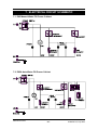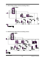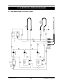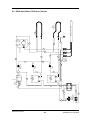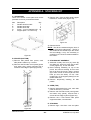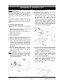
1
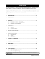
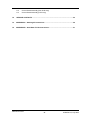
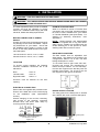
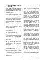
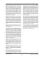
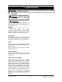
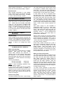
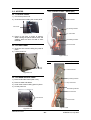
E85 PROOFER CABINETS
E85HLD PROOFER / HOLDING CABINETS
SERVICE
MANUAL
Revision 5/F3517
December, 2004
Manual P/N M0ME85
WARNING: ALL INSTALLATION AND SERVICE REPAIR WORK MUST BE CARRIED
OUT BY QUALIFIED PERSONS ONLY.
Revision 5/F3517
-2-
© Moffat Ltd, July 2004
CONTENTS
This manual is designed to take a more in depth look at the E85 prover and E85HLD prover /
holding cabinets for the purpose of making the unit more understandable to service people.
There are settings explained in this manual that should never require to be adjusted, but for
completeness and those special cases where these settings are required to change, this manual
gives a full explanation as to how, and what effects will result.
SECTION
PAGE NO.
1.
SPECIFICATIONS ........................................................................................................ 5
2.
INSTALLATION............................................................................................................ 8
3.
OPERATION ................................................................................................................. 9
3.1
3.2
3.3
4.
Description of Controls - E85 Models
Description of Controls - E85HLD Models
Explanation of Control System
MAINTENANCE ............................................................................................................ 13
4.1
4.2
Cleaning
Routine Procedures
5.
TROUBLE SHOOTING GUIDE..................................................................................... 15
6.
SERVICE PROCEDURES............................................................................................. 17
6.1
6.2
6.3
Fault Diagnosis
Access
Replacement
7.
ELECTRICAL SCHEMATICS ....................................................................................... 27
8.
ELECTRICAL WIRING DIAGRAMS ............................................................................. 29
9.
SPARE PARTS ............................................................................................................. 33
10.
ACCESSORIES / OPTIONS ......................................................................................... 34
11.
PARTS DIAGRAM........................................................................................................ 35
11.1
11.2
Main Assembly (Non HLD Only)
Main Assembly (HLD Only)
IMPORTANT: MAKING ALTERATIONS MAY VOID WARRANTIES AND APPROVALS.
Revision 5/F3517
-3-
© Moffat Ltd, July 2004
11.3
11.4
Control Panel Assembly (Non HLD Only)
Control Panel Assembly (HLD Only)
12.
SERVICE CONTACTS ................................................................................................. 43
13.
APPENDIX A. Stacking Kit Instructions ................................................................... 45
14.
APPENDIX B. Auto Water Fill Kit Instructions ......................................................... 47
Revision 5/F3517
-4-
© Moffat Ltd, July 2004
1. SPECIFICATIONS
880
(34.6)
150
(5.9)
902
880
(34.6)
(35.5)
MODEL: E85-8, E85A-8, E85-8HLD, E85A-8HLD
SIDE
40
(1.6)
FRONT
PLAN
LEGEND
- Electrical connection entry point
- Water entry - ¾” BSP (Autofill models only)
Dimensions shown in millimetres.
Dimensions in inches shown in brackets.
Revision 5/F3517
-5-
© Moffat Ltd, July 2004
880
(34.6)
150
(5.9)
1145
880
(34.6)
(45.1)
MODEL: E85-12, E85A-12, E85-12HLD, E85A-12HLD
40
SIDE
(1.6)
FRONT
PLAN
LEGEND
- Electrical connection entry point
- Water entry - ¾” BSP (Autofill models only)
Dimensions shown in millimetres.
Dimensions in inches shown in brackets.
Revision 5/F3517
-6-
© Moffat Ltd, July 2004
LOCATION
WATER SUPPLY CONNECTION
To ensure correct operation the following
minimum installation clearances are to be
adhered to:
(Autofill Models Only)
Max Pressure
Min Pressure
550 kPa / 5.5 bar / 80 psi
100 kPa / 1.0 bar / 15 psi
Rear
0mm / 0”
Left-hand side 0mm / 0”
Right-hand side 25mm / 1”
Provision must be allowed for the door
opening.
PROVER INTERNAL DIMENSIONS
E85-8
Width
Height
Depth
Prover Volume
460mm / 18”
700mm / 275/8”
660mm / 26”
0.21m³ / 7.5ft³
E85-12
Width
Height
Depth
Prover Volume
460mm / 18”
945mm / 371/4”
660mm / 26”
0.29m³ / 10.1ft³
PROVER RACK/PAN SIZE CAPACITY
Width
Depth
460mm/18” or 405mm/16”
660mm/26” or 760mm/30”
RACK POSITIONS
Number - E85-8: 8
- E85-12: 12
Spacing
76mm/3”
ELECTRICAL SUPPLY SPECIFICATION
OPTIONS
100-120 Volts A.C. 60 Hz, 14.5 A, 1.6kW
220-240 Volts A.C. 50 Hz, 7.2 A, 1.65kW
ELECTRICAL PLUG SPECIFICATION
REQUIREMENTS
Australia
3-pin 250V 10A, AS/NZ 3112
Canada
3-pin 120V 15A, NEMA 5-15
New Zealand
3-pin 250V 10A, AS/NZ 3112
United Kingdom 3-pin 250V 13A fused, BS
1363A
United States 3-pin 120V 15A, NEMA 5-15
Other Countries 3-pin 250V 10A minimum, type
to meet country standards
Revision 5/F3517
-7-
© Moffat Ltd, July 2004
2. INSTALLATION
WARNING: THIS APPLIANCE MUST BE GROUNDED.
WARNING: ALL INSTALLATION AND SERVICE REPAIR WORK MUST BE CARRIED
OUT BY QUALIFIED PERSONS ONLY.
It is most important that the proofer is installed
correctly and that the operation is correct
before use. Installation shall comply with local
electrical, health and safety requirements.
DOUBLE STACKING UNITS
When it is desired to mount a Turbofan E35
convection oven on an E85, a double stacking
kit must be used. Available from your dealer
or Turbofan distributor (see Spare Parts). For
stacking kit assembly instructions, refer
Appendix A.
BEFORE CONNECTION TO POWER
SUPPLY
Unpack and check unit for damage and report
any damage to the carrier and dealer. Report
any deficiencies to your dealer. Check that
the available power supply is correct to that
shown on the rating plate located on the righthand side panel.
NOTE: United Kingdom and USA/Canada
models are supplied with a top panel fitted.
Other country models are pre-fitted with the
double stacking kit on the proofer for direct
stacking under E35 convection ovens.
RACK WIDTH POSITIONS
100-120 Volts A.C. 60 Hz, 14.5 A, 1.6kW
220-240 Volts A.C. 50 Hz, 7.2 A, 1.65kW
The E85 models have an adjustable rack
width setting. This allows for the racking to be
configured for 405mm / 16” or 460 / 18” wide
baking sheets/pans or racks.
LOCATION
To set width remove right hand side rack.
Unscrew and remove four thumbscrews at
bottom and top of cabinet. For 16” wide trays,
turn the rack supports such that they face the
left side of the proofer. For 18” trays, turn the
rack supports to the right of the proofer.
To ensure correct operation the following
minimum installation clearances are to be
adhered to:
Rear
Left-hand side
Right-hand side
0mm / 0”
0mm / 0”
25mm / 1”
Provision must be allowed for the door
opening.
16” trays
ELECTRICAL CONNECTION
18” trays
Figure 2.2
E85 models are supplied with pre-fitted cords.
Ensure unit is fitted with correct cord and plug
for the installation (refer specifications
section).
RATING PLATE LOCATION
The rating plate for the E85 prover is located
at the bottom left corner of the RH side panel.
Should changing of the cord be necessary,
gain access to the electrical connection
terminal block and strain relief clamp by
removing the RH side panel.
L1
Phase
RED
BROWN
BLACK
L2
Ground
Neutral
BLACK
BLUE
WHITE
GREEN
GREEN/YELLOW
Rating Plate
WARNING: THIS APPLIANCE MUST
BE GROUNDED / EARTHED
Figure 2.1
Revision 5/F3517
Figure 2.3
-8-
© Moffat Ltd, July 2004
3. OPERATION
NOTE: A full user’s operation manual is supplied with the product and can be used for further
referencing of installation, operation and service.
3.1 DESCRIPTION OF CONTROLS - E85 PROVERS
1. POWER
O
UNIT IS OFF
I
UNIT IS ON (Indicator illuminates when
switched to this position)
2. THERMOSTAT
Temperature range 25 - 40°C (75 - 105°F).
Indicator illuminates when elements
cycling ON to maintain set temperature.
are
Controls the proofer air temperature.
1
3. HUMIDITY CONTROL
(Indicator illuminates when water tank
elements are cycling ON to maintain set
humidity).
Controls proofer humidity.
LO - Humidity setting for butter based pastries
(croissants, Danish pastries etc).
2
MED / HI - Humidity setting for yeast based
breads and dough.
WATER
Manual Water Fill Models: Open the proofer
door. Fill the water tank at the filling spout,
located at the front of the right hand side rack,
to approximately 20mm / ¾” from the top of
the tank. Remember to top up the water tank
when the water level is below the halfway
level in the tank and before the heating
element is exposed.
3
Auto Water Fill Models: Check that the water
tank is filling, and the heating element is well
covered. Unit must be switched on for water
tank auto-fill system to operate.
CONDENSATE PAN (Auto water fill models
only)
A pan is provided on guides underside the
cabinet for the collection of cabinet and door
condensation. Where provided, remove the
drain plugs in the cabinet floor centre and
door condensate channel below the door, to
allow condensate collection in the pan.
Remove the pan daily for emptying.
Revision 5/F3517
-9-
© Moffat Ltd, July 2004
3.2 DESCRIPTION OF CONTROLS - E85HLD PROVER/HOLDING CABINETS
1. FUNCTION
OFF
Unit is off.
PROOF Unit is in proofing mode. (Indicator
illuminates when switched to this position)
HOLD
Unit is in holding mode. (Indicator
illuminates when switched to this position)
2. THERMOSTAT
1
Temperature range 0 - 80°C (32 - 176°F).
Indicator illuminates when elements
cycling ON to maintain set temperature.
are
Controls the proofer air temperature.
3. HUMIDITY CONTROL
Proofing function only, redundant in hold
mode. (Indicator illuminates when elements
are cycling ON to maintain set humidity).
2
Controls proofer humidity.
LO - Humidity setting for butter based pastries
(croissants, Danish pastries etc).
MED / HI - Humidity setting for yeast based
breads and dough.
4. THERMOMETER
3
Dual Centigrade and Fahrenheit
Indicates cabinet temperature.
scale.
WATER
Manual Water Fill Models: Open the proofer
door. Fill the water tank at the filling spout,
located at the front of the right hand side rack,
to approximately 20mm / ¾” from the top of
the tank. Remember to top up the water tank
when the water level is below the halfway
level in the tank and before the heating
element is exposed.
4
Auto Water Fill Models: Check that the water
tank is filling, and the heating element is well
covered.
CONDENSATE PAN (Auto water fill models
only)
A pan is provided on guides underside the
cabinet for the collection of cabinet and door
condensation. Where provided, remove the
drain plugs in the cabinet floor centre and
door condensate channel below the door, to
allow condensate collection in the pan.
Remove the pan daily for emptying.
Revision 5/F3517
-10-
© Moffat Ltd, July 2004
3.3
and a water tank heating element controlled
by a mechanical bulb and capillary
thermostat.
EXPLANATION OF CONTROL
SYSTEM
The E85 Prover and Prover/Holding Cabinets
feature operator controls and an electrical
circuit for which a direct understanding of their
operation is required before carrying out any
service work or fault repair work. The control
device functions and electrical circuit are
explained as follows:
The air heating element is positioned in the
bottom of the air circulation ducting inside the
cabinet and is directly controlled by the useradjustable thermostat mounted to the control
panel.
The thermostat sensing bulb is
mounted inside the cabinet to control the
cabinet air temperature to the control panel
setting. An indicator light on the control panel
above this thermostat will illuminate when the
thermostat has the air heating element
operating and will cycling Off with the
thermostat to indicate when the temperature
reaches set point.
A rotary switch on the control panel of these
models functions as the power On/Off switch
of the unit by isolating the Line 1 phase
supply.
E85 Prover only models this switch is a 2 pole
device, with 1 pole isolating power to the air
circulation fan motor and the other pole
isolating power to the water tank heating
element controls and the dry heating element
controls.
The water tank heating element controlled by
the humidity level thermostat mounted to the
control panel is used to heat the water tank
water and maintain the water tank
temperature between 50°C (122°F) and 80°C
(176° F). This water tank temperature is
controlled by the humidity level thermostat
setting between the adjustments of low and
high humidity. The evaporation rate of the
water in the water tank dependent on its
temperature, provides humidity into the
cabinet and accordingly the setting of the
humidity thermostat controls the rate of
evaporation and therefore the humidity level in
the cabinet.
On E85HLD Prover/Holding Cabinet models
this switch is a 3 position, 4 pole, multifunction switch which in the Off position opens
circuits all poles and isolates power from all
control and heating systems.
In the ‘Proof’ position poles P3 and P4 are
closed, operating the electrical circuit
functions as follows:
P3 – Humidity control thermostat
P4 – Air heating thermostat, air circulation
motor and control panel power indicator.
An indicator light on the control panel above
the humidity dial illuminates when the water
tank element is On, and cycles Off when the
thermostat switches the heating element Off
to provide an indication of the humidity
control. The sensing bulb of the humidity
thermostat is mounted directly on the water
tank heating element which are both
immersed in the water tank. Should the water
tank level drop below the heating element the
humidity thermostat will cycle Off due to the
sensing bulb reacting to the radiated heat off
the heating element and will prevent the
humidity water tank heating element burning
out through excessive temperature.
In the ‘Hold’ function position pole P4 remains
closed, pole P3 opens to isolate the humidity
control, and pole P2 closes. Power to pole P2
is fed from the air heating thermostat and
switches power through to the additional hold
heating element.
With both E85 Prover and E85HLD Prover/
Holding Cabinets this power and power
function switch will also switch power on Auto
water-fill models to the water solenoid
switching relay.
E85 Auto-Water fill models provide for a
mains cold water supply connection for automatic water tank filling and level control. NonAuto water-fill models require the operator to
manually fill the water tank and maintain the
water tank level as the water evaporates
through operation.
The air circulation fan and control panel power
indicator are On continuously on all E85
models when the power or power/function
switch are in an On position.
The proofing system operates on all models,
controls air temperature and humidity levels
by way of an air heating element controlled by
a mechanical bulb and capillary thermostat
Revision 5/F3517
On auto water-fill models, an electric water
-11-
© Moffat Ltd, July 2004
solenoid, float switch and relay maintain the
water level in the humidity tank. The float
switch is mounted at the rear of the water
tank, and when below the full water level
position, it open circuits, removing power from
the relay coil, and therefore allowing power
through the normally closed contact of the
relay to energise the water solenoid. As the
water reaches the full level position the float
switch will close circuit, energising the relay
and therefore removing power from the
normally closed position of the relay, thus
turning off the water solenoid.
the 25° C (77° F) as higher proofing
temperatures will cause the butter to melt out
of the product. For yeast based doughs and
breads the proofing temperature should be set
higher at around 40°C (105°F) in order to
activate the yeast in these products. On
E85HLD models temperatures higher than
this are used for holding food at required
serving temperatures and the thermometer
dial on the control panel of these models is
provided to indicate and verify the actual
cabinet temperature and assist with the
thermostat setting.
Ensuring that the power or power function
switch is in the Off position is necessary
whenever removing the removable water tank
for cleaning, as when the water tank is
removed the float switch drops and the water
solenoid valve will be opened if the electrical
circuit is switched On. Therefore as a
precaution the mains water supply should also
be switched Off whenever removing the water
tank.
On all models the air circulation fan mounted
at the top of the air delivery ducting ensures
that the temperature and humidity throughout
the cabinet is even by creating a low velocity
air circulation system throughout the prover
cabinet. This system overcomes the natural
occurrence of hot air rising and therefore
higher humidity and temperature in the upper
positions of the cabinet as found with proofing
units without forced air circulation.
E85HLD Prover/Holding Cabinets are able to
be operated both as a proofing cabinet and as
a holding cabinet.
The user-adjustable thermostat and humidity
controls are required to allow adjustment of
cabinet temperature and humidity levels for
the variations of temperature and humidity
that different product types require.
As explained in earlier paragraphs, when the
power function switch on these models is
selected to the ‘Hold’ position the humidity
control circuit is turned Off and an additional
air heating element is connected into the air
temperature thermostat circuit. In this mode
the air temperature thermostat operates as it
does in the proofing mode, however, in this
case there is an additional air heating element
switched On and Off to provide extra heating
power in this mode. The additional air heating
element in these models is also mounted in
the air circulation ducting.
E85HLD Prover/Holding Cabinets are also
provided with a thermometer dial on the
control panel to provide an indication of the
cabinet temperature and the sensing bulb of
this thermometer dial is mounted next to the
sensing bulb of the main thermostat inside the
cabinet.
On E85 Prover only models the main
thermostat is adjustable up to 40°C (105°F)
whereas on E85HLD Prover/Holding Cabinet
models the main thermostat is adjustable up
to 80°C (175°F).
With both models butter based products such
as croissants and danish pastries should have
the cabinet proofing temperature set around
Revision 5/F3517
-12-
© Moffat Ltd, July 2004
4. MAINTENANCE
WARNING: ALL INSTALLATION AND SERVICE REPAIR WORK MUST BE CARRIED
OUT BY QUALIFIED PERSONS ONLY.
4.1 CLEANING
WARNING: ALWAYS TURN THE
POWER SUPPLY OFF BEFORE
CLEANING.
IMPORTANT: THIS UNIT IS NOT
WATER PROOF.
DO NOT USE A WATER JET SPRAY TO
CLEAN INTERIOR OR EXTERIOR OF
THIS UNIT.
CABINET
A good quality stainless steel cleaning
compound is recommended for cleaning the
inside and outside of the cabinet. Harsh
abrasive cleaners may damage the surface.
SIDE RACKS
To remove, take hold of the centre rung and
lift towards the proofer top. To replace, hold
horizontally, engage in holes and push down.
DOOR
Wash with warm water and detergent solution
using a soft sponge in straight lines up and
down the door.
Rinse with clean, warm water to remove
detergent. Dry off.
WATER TROUGH
Remove right hand side rack and remove
trough. Clean with warm, soapy water. Rinse
thoroughly.
WATER TROUGH ELEMENT
When the element becomes limed / scaled,
remove water trough and clean. Replace
water trough and half fill with white vinegar or
acetic acid then fill to the normal level with
water. Switch unit on. Set humidity control to
‘Hi’ and run for approximately 30 minutes.
Remove trough and clean element with damp
cloth when cooled. Wash out trough and refit.
This procedure is recommended to be done
once a week. Frequency of cleaning the
element may be increased or decreased
depending on the lime depositing on the
element.
Revision 5/F3517
-13-
© Moffat Ltd, July 2004
4.2 ROUTINE PROCEDURES
PROCEDURE
INTERVAL
WET ELEMENT
Remove scaling (refer section 4.1).
As required
DOOR SEALS
(E85HLD models only)
Inspect door seals on door inside for wear and tear.
DOOR HINGES
Check for wear.
12 months
ELEMENTS
Check that elements are operating.
12 months
Revision 5/F3517
-14-
6 months
© Moffat Ltd, July 2004
5. TROUBLE SHOOTING
WARNING: ALL INSTALLATION AND SERVICE REPAIR WORK MUST BE CARRIED
OUT BY QUALIFIED PERSONS ONLY.
FAULT
THE UNIT DOES NOT
OPERATE / START
POSSIBLE CAUSE
The unit is not plugged into the
wall socket.
REMEDY
Plug in.
The mains isolating switch on
Turn on.
the wall, circuit breaker or fuses
are “off” at the power board.
The power switch on the unit is
off.
Depress switch. Switch will
illuminate.
Incorrect electrical supply.
(Refer fault diagnosis 6.1.1)
Ensure electrical supply correct.
Power switch faulty (E85).
(Refer fault diagnosis 6.1.1)
Replace.
(Refer service section 6.3.2)
Function switch faulty (E85HLD) Replace.
(Refer fault diagnosis 6.1.1)
(Refer service section 6.3.2)
PROOFING OR HOLDING
MODE NOT WORKING
(E85HLD models only)
Power / selector switch faulty.
(Refer fault diagnosis 6.1.2)
Replace.
(Refer service section 6.3.2)
FAN DOES NOT OPERATE
Faulty fan motor.
(Refer fault diagnosis 6.1.3)
Replace.
(Refer service section 6.3.8)
NO HEAT
Thermostat faulty.
(Refer fault diagnosis 6.1.2)
Replace.
(Refer service section 6.3.3)
Function switch faulty (E85HLD) Replace.
(Refer fault diagnosis 6.1.2)
(Refer service section 6.3.2)
Element blown.
(Refer fault diagnosis 6.1.4)
Replace.
(Refer service section 6.3.5)
NO TEMPERATURE
CONTROL
Faulty thermostat.
(Refer fault diagnosis 6.1.5)
Replace.
(Refer service section 6.3.3)
NO HUMIDITY
No water in trough.
(Manual fill models)
Fill trough with water.
Auto-fill system faulty.
(Auto-fill models only)
(Refer Fault: Auto-fill not
working)
Faulty thermostat.
(Refer fault diagnosis 6.1.6)
Replace.
(Refer service section 6.3.4)
Function switch faulty (E85HLD) Replace.
(Refer fault diagnosis 6.1.2)
(Refer service section 6.3.2)
NO HUMIDITY CONTROL
Revision 5/F3517
Water tank element blown.
(Refer fault diagnosis 6.1.6)
Replace.
(Refer service section 6.3.6)
Faulty thermostat.
(Refer fault diagnosis 6.1.7)
Replace.
(Refer service section 6.3.4)
-15-
© Moffat Ltd, July 2004
FAULT
SLOW RECOVERY
POSSIBLE CAUSE
REMEDY
Overloading of product.
Reduce batch size.
Door opened unnecessarily.
Do not open unnecessarily.
Electrical supply incorrect.
Check supply voltage is as per
rating plate voltage.
Door seals deteriorated.
(E85HLD models only)
Inspect and replace.
Fan motor faulty.
(Refer fault diagnosis 6.1.3)
Replace.
(Refer service section 6.3.8)
NO HEATING / HUMIDITY
INDICATOR
Indicator faulty.
(Refer fault diagnosis 6.1.8)
Replace.
(Refer service section 6.3.1)
DOOR DOES NOT CLOSE
Tray in way of door.
Correctly position tray in rack.
Interference with door.
Inspect and repair.
Hinges damaged.
Replace.
(Refer service section 6.3.10)
Water supply not turned on.
Turn water supply on.
Blockage in water supply.
Disconnect water supply and
inspect.
AUTOFILL WATER NOT
FILLING
(Autofill models only)
Water connection filter blocked. Clean filter.
AUTOFILL WATER OVERFLOWING
(Autofill models only)
Revision 5/F3517
Water solenoid faulty.
(Refer fault diagnosis 6.1.9)
Replace.
(Refer service section 6.3.14)
Solenoid relay faulty.
(Refer fault diagnosis 6.1.9)
Replace.
(Refer service section 6.3.13)
Water level float switch faulty.
(Refer fault diagnosis 6.1.9)
Replace.
(Refer service section 6.3.15)
Water level float switch faulty.
(Refer fault diagnosis 6.1.9)
Replace.
(Refer service section 6.3.15)
Solenoid relay faulty.
(Refer fault diagnosis 6.1.9)
Replace.
(Refer service section 6.3.13)
Water tank not fitted.
Fit water tank.
-16-
© Moffat Ltd, July 2004
6. SERVICE PROCEDURES
WARNING: ENSURE POWER SUPPLY IS SWITCHED OFF BEFORE SERVICING.
WARNING: ALL INSTALLATION AND SERVICE REPAIR WORK MUST BE CARRIED
OUT BY QUALIFIED PERSONS ONLY.
SECTION
6.1
FAULT DIAGNOSIS .............................................................................................................18
6.1.1
6.1.2
6.1.3
6.1.4
6.1.5
6.1.6
6.1.7
6.1.8
6.1.9
6.2
Unit Does Not Operate / Start..............................................................................18
Proof or Hold Mode Not Working (HLD Models Only) .........................................18
Fan Does Not Operate ........................................................................................18
No Heat ...............................................................................................................18
No Temperature Control......................................................................................18
No Humidity .........................................................................................................18
No Humidity Control ............................................................................................19
No Heating / Humidity Indicator...........................................................................19
Autofill Not Filling or Overflowing (Autofill Models Only) .....................................19
ACCESS ...............................................................................................................................20
6.2.1
6.2.2
6.2.3
6.2.4
6.3
PAGE NO.
Control Panel.......................................................................................................20
Right Hand Side Panel ........................................................................................20
Right Hand Rear Service Panel...........................................................................20
Control Panel (Rear)............................................................................................20
REPLACEMENT ...................................................................................................................21
6.3.1
6.3.2
6.3.3
6.3.4
6.3.5
6.3.6
6.3.7
6.3.8
6.3.9
6.3.10
6.3.11
6.3.12
6.3.13
6.3.14
6.3.15
Indicator Light ......................................................................................................21
Power /Function Switch .......................................................................................21
Thermostat ..........................................................................................................21
Humidity Thermostat ...........................................................................................22
Dry Element.........................................................................................................22
Wet Element ........................................................................................................22
Fan .....................................................................................................................23
Motor ...................................................................................................................23
Door.....................................................................................................................24
Door Hinges.........................................................................................................24
Door Seals...........................................................................................................24
Thermometer .......................................................................................................24
Relay ...................................................................................................................25
Water Solenoid ....................................................................................................25
Float Switch .........................................................................................................25
Revision 5/F3517
-17-
© Moffat Ltd, July 2004
6.1 FAULT DIAGNOSIS
terminal 2 then switch is faulty—replace.
6.1.1 UNIT DOES NOT OPERATE / START
If power checks are ok, but PROOF mode not
working, review fault diagnosis procedure and
trouble-shooting guide for further assistance.
Incorrect electrical supply
HOLD position function test
Check that the supply voltage across phase
and neutral (L1 and L2) terminals of terminal
block is correct as per the voltage stated on
the unit’s electrical rating plate. If incorrect,
check electrical connection of supply cord,
and/or check electrical supply.
With function switch in HOLD position check
terminals P3, P4, 4, P2 and 2 have power with
thermostat set to maximum position.
Check terminal 3 has no power. If power at
terminal 3 then switch is faulty—replace.
If power checks are ok, but HOLD mode not
working, review fault diagnosis procedure and
trouble-shooting guide for further assistance.
Power switch on unit faulty (E85 models)
With power supply on check power to
terminals P1 and P2 on unit power on/off (I/O)
switch. If no power, check electrical supply
and wiring.
6.1.3 FAN DOES NOT OPERATE
Fan motor faulty
If power to P1 and P2, turn power switch to on
(I) and check power is switched through to
terminals 1 and 2. If either 1 or 2 terminals
have no power, switch is faulty—replace. If
checks are ok and unit still does not operate,
check unit’s wiring and/or re-diagnose exact
fault with unit and refer to trouble-shooting
guide.
Check the supply voltage across motor
terminals. If there is no voltage with function
switch on then check the electrical connections of supply wiring.
If voltage is correct then check the oven fan
for free rotation. Remove any obstruction.
If fan is free to spin and the voltage supply is
correct, then the motor is faulty—replace.
Function switch on unit faulty (E85HLD
models)
6.1.4 NO HEAT
Thermostat faulty
With power supply on, check power to
terminals P3 and P4 of unit’s function switch.
If no power, check electrical supply and
wiring.
With cold proofer, set thermostat to 40°C /
105°F. Check power to terminal 1 of top
thermostat. If there is no power then check
wiring.
If power to P3 and P4, turn function switch to
PROOF position and check power is switched
through to terminals 3 and 4 on function
switch. If either 3 or 4 have no power then
switch is faulty—replace.
Element blown
If checks are ok and the unit still does not
operate, check the unit’s wiring and/or
re-diagnose exact fault with unit and refer to
trouble-shooting guide.
With thermostat on and heating check voltage
across dry element terminals. If there is no
voltage check wiring. If voltage is correct,
element is faulty - replace.
6.1.3 PROOF OR HOLD MODE NOT
WORKING (E85HLD MODELS ONLY)
6.1.5 NO TEMPERATURE CONTROL
Power / function selector switch faulty
With thermostat in off position (fully counterclockwise), the heating indicator should be off.
If not, then the thermostat is faulty - replace.
Check power at terminal 2. If there is no
power then the thermostat is faulty - replace.
Thermostat faulty
Check function switch as per 6.1.1 first to
ensure power switching of switch works.
Follow by:PROOF position function test
6.1.6 NO HUMIDITY
With function switch in PROOF position check
terminals P3, 3, P4, 4 and P2 have power with
thermostat set to maximum position.
Humidity thermostat faulty
With cold proofer, set humidity to ‘HI’. Check
power to terminal 1 of bottom thermostat. If
there is no voltage then check wiring.
Check terminal 2 has no power. If power at
Revision 5/F3517
-18-
© Moffat Ltd, July 2004
Check power at terminal 2. If there is no
power then the thermostat is faulty - replace.
over relay switching the solenoid valve on/off
as required to maintain water supply to the
water tank. The relay has power supplied to
its coil (terminal 8) from the float switch when
the float switch is in the water FULL position.
Element blown
With humidity thermostat on and heating
check voltage across wet element terminals.
If there is no voltage check wiring. If voltage
is correct, element is faulty - replace.
In other words, the relay is energised when
the water tank is full. In this state the relay
switches power off the solenoid valve. When
the water level lowers the float switch open
circuits and power is removed from the relay
coil. This switches the relay contacts to the
normally closed position which then supplies
power through to the solenoid valve to supply
water. Check correct solenoid operation as
follows.
6.1.7 NO HUMIDITY CONTROL
Humidity thermostat faulty
Switch the proofer on and set the humidity to
‘LO’. Check that the humidity thermostat
cycles on / off, and using a suitable probe
measure the temperature of the water in the
trough. The water temperature should be 50°
C/120°F ± 10%. If the temperature continues
to rise above this then the humidity thermostat
is faulty - replace.
With power supply on and POWER or
FUNCTION switch on unit on, check relay
terminals no 6 and 5 have power. If not check
wiring. With water tank empty the relay coil
should have no power. Check voltage across
terminals 7 and 8. If coil is energised and
water tank is empty check float switch for
possible fault, refer below.
6.1.8 NO HEATING / HUMIDITY
INDICATOR
With no power to relay coil, the relay contacts
should be in the normally closed position, and
power should be on terminals 1 and 2, one of
which is wired to the solenoid. If no power at
1 and 2 with relay de-energised check wiring.
If ok relay is faulty—replace.
Indicator faulty
Check voltage across indicator terminals with
controls on and appropriate thermostat turned
on fully. If the voltage is correct and indicator
is not illuminated then the indicator is faulty replace. If there is no voltage then check
wiring.
Check relay contact terminal nos 3 and 4
when relay is energised. Either fill water tank
with water, or hold float switch up in fully
raised position. With float switch in this
position power from relay terminals 5 and 6
should be supplied to coil terminal 8 on relay
through float switch. If not then float switch
has a possible fault, refer below.
6.1.9 AUTOFILL NOT FILLING OR OVERFLOWING (AUTOFILL MODELS)
Water solenoid faulty
Empty water tank so float switch is in lowest
position. With power ON check voltage
across water solenoid coil terminals.
If
voltage is correct (refer electrical rating plate)
but solenoid is not operating, disconnect
electrical supply and remove wire connections
from solenoid. Check solenoid coil windings
resistance.
Correct coil resistance:
220-240 volt models
110-120 volt models
Water level float switch faulty
The water tank float switch is mounted at the
rear of the water tank inside the cabinet. With
the water level full (float switch raised) the
float switch should be closed circuit to
energise the water solenoid relay and remove
power from the water solenoid. With the
water level down (below full and float switch
dropped), the float switch should be open
circuit to de-energise the relay, which will then
switch power to the water solenoid through its
normally closed contacts.
3650 ohms
1100 ohms
NOTE: If open circuit/high resistance, then
the coil is faulty– replace.
If coil is correct, rewire and listen for audible
solenoid click when power is supplied. If
solenoid can be heard functioning and water
supply is turned on but no water is entering
tank, remove water solenoid and fittings and
check for blockages.
To check correct operation of float switch
remove the float switch wire connections from
terminal 8 and terminal 5 on relay. Check
switch continuity and wire ends. With full
water tank float switch should be closed
circuit. With empty water tank float switch
should be open circuit. If not, float switch is
faulty—replace.
Solenoid relay faulty
The water solenoid valve has a 2 pole change
Revision 5/F3517
-19-
© Moffat Ltd, July 2004
6.2 ACCESS
6.2.4 CONTROL PANEL—REAR (E85)
6.2.1 CONTROL PANEL
1) Pull off the power knob.
2) Undo the screw holding the control panel.
Power Indicator
One Screw
Dry Heating Indicator
Figure 6.2.1
Dry Thermostat
3) Panel is now free to hinge at bottom.
When closing the panel ensure wires and
capillary tube are clear of metal or other
terminals.
Wet Heating Indicator
Wet Thermostat
6.2.2 RH SIDE PANEL
1) Undo the four screws holding the panel in
place.
2) Lift the panel out.
Figure 6.2.4
6.2.5 CONTROL PANEL—REAR (E85-HLD)
Four
Screws
Power Indicator
Figure 6.2.2
6.2.3 RH REAR SERVICE PANEL
Dry Heating Indicator
1) Remove RH side Panel (refer 6.2.2).
2) Remove water inlet elbow.
Dry Thermostat
3) Undo three screws holding panel in place.
4) Lift the panel out.
Wet Heating Indicator
Wet Thermostat
Three Screws
Thermometer
Figure 6.2.5
Figure 6.2.3
Revision 5/F3517
-20-
© Moffat Ltd, July 2004
6.3 REPLACEMENT
Support
Bracket Screw
6.3.1 INDICATOR LIGHT
1) With control panel open (refer 6.2.1)
remove the wires from the back of the
neon.
Thermostat Phial
(E85 models)
Figure 6.3.3
Neon Wires
Thermostat Phial
(E85HLD models)
Support
Bracket Screw
Figure 6.3.1
Figure 6.3.4
2) From back push neon through front of
panel rotating clockwise.
4) Withdraw old thermostat phial through
hole under bracket in side of proofer.
3) Push new neon in from front of panel, and
reconnect wires.
5) Remove sleeving from old thermostat and
fit to replacement thermostat.
Thermostat Phial
(E85 models only)
6.3.2 POWER / FUNCTION SWITCH
1) With control panel open (refer 6.2.1)
remove the two screws securing the switch
to the bracket and remove.
Plastic Sleeving
Figure 6.3.5
Two Screws
Fibreglass Sleeve
Thermostat Phial
(E85HLD models only)
Figure 6.3.2
Figure 6.3.6
2) Mount new switch and transfer wires from
the old switch.
6) Undo two screws securing thermostat to
control panel and remove.
Two Screws
6.3.3 THERMOSTAT
1) Pull knob off front of thermostat.
2) Open control panel (refer 6.2.1).
3) With door open, remove right hand side
rack. Undo thermostat support bracket
screw and remove bracket.
Figure 6.3.7
Revision 5/F3517
-21-
© Moffat Ltd, July 2004
7) Attach new thermostat to control panel
and transfer wires to new thermostat.
7) Attach new thermostat to control panel,
and transfer wires to new thermostat.
8) Re-assemble in reverse order.
8) Re-assemble in reverse order.
6.3.5 DRY ELEMENT
6.3.4 HUMIDITY THERMOSTAT
1) Remove RH side panel (refer 6.2.2), remove wires from (rear) element terminals,
noting position.
1) Pull knob off front of thermostat
2) Open control panel (refer 6.2.1).
3) With door open, remove right hand side
rack and water trough. Undo thermostat
support bracket screw and remove
bracket. Remove clip holding capillary to
element.
Additional
Heating Element
Terminals (HLD
models only)
Support
Bracket
Screw
Element
Terminals
Capillary
Clip
Figure 6.3.11
2) With door open, remove right hand side
rack.
Figure 6.3.8
3) Undo the four screws holding the fan baffle
and remove baffle.
4) Remove rubber bush in side wall, withdraw
old thermostat phial through side of
proofer.
5) Remove fibreglass sleeving from old
thermostat and fit to replacement
thermostat.
Baffle
Screws
Fibreglass Sleeve
Figure 6.3.12
Thermostat Phial
4) Unscrew the element from RH side
(outside) of proofer. Pull element carefully
to remove from inside of proofer.
Figure 6.3.9
5) Replace and re-assemble in reverse
order.
6) Undo two screws securing thermostat to
control panel and remove.
Dry Element Ratings
Two Screws
110-120volt bottom (All models)
15.5 ohms
110-120 volt top (HLD models only) 20.1 ohms
220 - 240 Volt
73 ohms.
6.3.6 WET ELEMENT
1) Remove RH side panel (refer 6.2.2), and
remove wires from (rear) element
terminals.
Figure 6.3.10
Revision 5/F3517
-22-
© Moffat Ltd, July 2004
2) With door open, remove right hand side
rack and water tank.
3) Whilst holding the fan blades, undo the nut
in the centre of the fan (LH thread) and
remove the fan.
3) Remove thermostat support bracket screw
(on element) and remove bracket.
4) Remove clip securing thermostat capillary
to element.
Centre Nut
Support
Bracket
Screw
Capillary
Clip
Figure 6.3.16
Figure 6.3.13
4) Replace and reassemble in reverse order.
5) Unscrew the element from RH side
(outside) of proofer.
6.3.8 MOTOR
1) Remove fan (refer 6.3.8).
2) Remove RH side panel (refer 6.2.2)
Element
Screws
3) Remove wires from fan motor, noting their
positions.
Figure 6.3.14
6) Pull element carefully into proofer to
remove.
Fan Motor
Terminals
7) Replace and reassemble in reverse order.
Wet Element Ratings
110 - 120 Volt
15.5 ohms
220 - 240 Volt
73.1 ohms
Figure 6.3.17
4) Remove three screws from inside proofer
securing motor and remove from outside.
6.3.7 FAN
1) With the door open, remove the right hand
side rack.
2) Undo the four screws holding the fan baffle
and remove the baffle.
Three
Screws
Baffle
Screws
Figure 6.3.18
5) Replace and reassemble in reverse order.
Figure 6.3.15
Revision 5/F3517
-23-
© Moffat Ltd, July 2004
4) Rivet new hinges to door and secure to
E85 proofer with screws.
6.3.9 DOOR
1) Open prover door.
5) Re-hang door on proofer.
2) Lift door vertically off hinges.
3) Remove door handle (two screws).
6.3.11 DOOR SEALS - HLD MODELS ONLY
1) Open prover door.
2) Undo and remove 16 screws securing
door seal retaining strips to door.
Two Screws
Screws
(16)
Figure 6.3.19
4) Drill out rivets securing hinges to old door
frame (two per hinge).
Figure 6.3.22
3) Remove the door seal, replace, and
re-assemble in reverse order.
6.3.12 THERMOMETER - HLD MODELS
Rivets
1) Open control panel (refer 6.2.1)
2) With door open, remove right hand side
rack (Lift off supports, and remove).
3) Undo thermometer support bracket screw
and remove bracket.
Figure 6.3.20
5) Secure door handle and catch plate to
new door.
6) Rivet hinges to new door frame.
Support
Bracket Screw
7) Re-hang door on E85 proofer.
6.3.10 DOOR HINGES
Figure 6.3.23
1) Open prover door.
2) Lift door vertically off hinges.
4) Withdraw old thermometer phial through
hole under bracket in side of cabinet.
3) Drill out rivets securing hinges to door and
screws securing hinges to E85 proofer,
and remove hinges.
5) Undo 2 nuts securing thermometer to
control panel and remove.
Two Nuts
Hinge
Rivets
Hinge
Screws
Door
Hinges
Figure 6.3.21
Revision 5/F3517
Figure 6.3.24
-24-
© Moffat Ltd, July 2004
6) Attach new thermometer to control panel
and transfer wires to new thermometer.
5) Remove two screws securing solenoid to
bracket, and remove the water solenoid.
7) Insert new thermometer phial through
cabinet side and re-attach bracket.
6.3.13 RELAY - AUTOFILL MODELS ONLY
Two Screws
1) Remove RH side panel (refer 6.2.2).
2) Remove two screws securing relay to
bracket.
Figure 6.3.28
6) Secure new solenoid with screws, and
re-assemble in reverse order.
Two Screws
Figure 6.3.25
6.3.15 FLOAT SWITCH - AUTOFILL
MODELS ONLY
3) Secure new relay to bracket.
4) Transfer wires from old relay to new relay.
1) Remove RH side panel (refer 6.2.2).
5) Replace RH side panel.
2) Remove float switch wires from relay,
noting their positions.
3) Remove brass fitting from rear of float
switch.
6.3.14 WATER SOLENOID - AUTOFILL
MODELS ONLY
1) Remove RH side panel (refer 6.2.2) and
RH rear service panel (refer 6.2.3).
Two Nuts
2) Remove wires from solenoid, noting their
positions.
Solenoid Wires
Brass Fitting
Figure 6.3.29
Brass Fitting
4) Remove RH side rack and water trough
from inside proofer.
Figure 6.3.26
5) Undo two nuts from outside cabinet, and
two screws inside cabinet securing float
switch bracket to proofer. (Refer figure
6.3.28).
3) Remove brass fitting from solenoid (refer
figure 6.3.23).
4) Remove two screws securing solenoid to
proofer, and withdraw solenoid assembly.
6) Remove
proofer.
float
switch
assembly
from
NOTE: The float switch bracket has been
silicone sealed, so it may therefore be
necessary to cut around the bracket with a
sharp knife to assist with removal. Clean
off all remaining silicone.
7) Remove the float switch sleeve, and undo
the nut securing the float switch to the
bracket.
Two Screws
Figure 6.3.27
Revision 5/F3517
-25-
© Moffat Ltd, July 2004
Float Switch
Sleeve
Float Switch
Nut
Float Switch
Figure 6.3.30
8) Remove the float switch from the bracket,
replace, and reassemble in reverse order.
Revision 5/F3517
-26-
© Moffat Ltd, July 2004
7. ELECTRICAL CIRCUIT SCHEMATIC
7.1 E85 Manual Water Fill Prover Cabinet
7.2 E85A Auto Water Fill Prover Cabinet
Revision 5/F3517
-27-
© Moffat Ltd, July 2004
7.3 E85-HLD Manual Water Fill Prover/Holding Cabinet
7.4 E85A-HLD Auto Water Fill Prover/Holding Cabinet
Revision 5/F3517
-28-
© Moffat Ltd, July 2004
6
2
5
Revision 5/F3517
2
-29-
EARTH
1
2
WET
THERMOSTAT
(50-80°C)
1
DRY
THERMOSTAT
(0-40°C)
P1
P2
1
1
2
POWER
SWITCH
9
7
4
PILOT
LIGHT
PILOT
LIGHT
18
POWER
INDICATOR
1
MAINS
TERMINAL
BLOCK
12
11
3
10
L
13
8
N
15
E
17
FAN MOTOR
16
14
19
WET
ELEMENT
POWER SUPPLY CORD
EARTH
DRY
ELEMENT
8. ELECTRICAL WIRING DIAGRAM
8.1 E85 Manual Water Fill Prover Cabinet
© Moffat Ltd, July 2004
Revision 5/F3517
-30-
WATER
SOLENOID
FLOAT SWITCH
23
24
21
24
22
5
3
1
RELAY
6
4
2
20
6
7
8
2
5
2
EARTH
1
2
WET
THERMOSTAT
(50-80°C)
1
DRY
THERMOSTAT
(0-40°C)
P1
P2
1
1
2
POWER
SWITCH
9
7
4
PILOT
LIGHT
PILOT
LIGHT
18
POWER
INDICATOR
1
23
MAINS
TERMINAL
BLOCK
12
11
3
10
L
13
8
N
15
E
17
FAN MOTOR
16
14
19
WET
ELEMENT
POWER SUPPLY CORD
EARTH
DRY
ELEMENT
8.2 E85A Auto Water Fill Prover Cabinet
© Moffat Ltd, July 2004
6
2
-31-
EARTH
1
2
WET
THERMOSTAT
(50-80°C)
1
Revision 5/F3517
DRY
THERMOSTAT
(0-85°C)
P4
2
P3
2
4
21
3
P1
P2
1
1
2
FUNCTION
SWITCH
4
2
6
9
20
5
8
21
4
PILOT
LIGHT
PILOT
LIGHT
18
1
MAINS
TERMINAL
BLOCK
12
11
POWER
INDICATOR
3
10
L
13
N
15
15
E
17
FAN MOTOR
16
14
19
20
8
POWER SUPPLY CORD
EARTH
WET
ELEMENT
HOLD
ELEMENT
800W 110V
800W 240V
DRY
ELEMENT
8.3 E85-HLD Manual Water Fill Prover/Holding Cabinet
© Moffat Ltd, July 2004
-32-
FLOAT SWITCH
WATER
SOLENOID
23
24
21
24
22
5
3
1
RELAY
6
4
2
20
7
8
6
2
EARTH
1
2
WET
THERMOSTAT
(50-80°C)
1
Revision 5/F3517
DRY
THERMOSTAT
(0-85°C)
P4
2
P3
2
4
26
3
P1
P2
1
1
2
FUNCTION
SWITCH
4
6
9
8
26
20
2
25
5
PILOT
LIGHT
7
4
18
12
1
23
MAINS
TERMINAL
BLOCK
PILOT
LIGHT
11
POWER
INDICATOR
3
10
L
13
8
N
15
15
E
17
FAN MOTOR
16
14
19
25
POWER SUPPLY CORD
EARTH
WET
ELEMENT
HOLD
ELEMENT
800W 110V
800W 240V
DRY
ELEMENT
8.4 E85A-HLD Auto Water Fill Prover/Holding Cabinet
© Moffat Ltd, July 2004
9. SPARE PARTS
PART NO
DESCRIPTION
CONTROLS
020822
022789
020823
014233
022787
020823
015485
021472
020849
022788
Switch - Power (Non HLD only)
Switch - Function (HLD only)
Knob - Power / Function
Thermostat (Temperature) (Non HLD only)
Thermostat (Temperature) (HLD only)
Knob - Thermostat
Thermostat (Humidity)
Knob - Humidity Thermostat
Neon Indicator
Thermometer (HLD only)
AUTO FILL OPTION
020851
Solenoid Valve (220-240V)
021617
Solenoid Valve (110V)
021534
Relay (220-240V)
021535
Relay (110V)
022250
Float Switch
022294
Auto Fill Upgrade Kit (240V)
022300
Auto Fill Upgrade Kit (110V)
MOTOR & ELEMENTS
022042
Fan
013431
Motor (220-240V)
025387
Motor (110V)
021694
Dry Element 800W (220-240V)
021693
Bottom Dry Element 800W (110V)
022774
Top Dry Element 600W (110V HLD only)
021696
Wet Element (220-240V)
021695
Wet Element (110V)
DOOR
021434
022768
021436
022769
021468
021663
018947
022758
022989
022990
Door Assembly - 8 tray (Non HLD only)
Door Assembly - 8 tray (HLD only)
Door Assembly - 12 tray (Non HLD only)
Door Assembly - 12 tray (HLD only)
Handle
Hinge
Magnetic Catch
Chrome Catch Plate (HLD only)
Door Seal - 8 Tray (HLD only)
Door Seal - 12 Tray (HLD only)
RACKS
021416
021417
Side Rack - 8 tray
Side Rack - 12 tray
Revision 5/F3517
-33-
© Moffat Ltd, July 2004
10. ACCESSORIES
DOUBLE STACKING KIT (PART NO 22299)
- For use with E35 convection ovens
6” LEG OPTION (PART NO 18724 x4)
Revision 5/F3517
-34-
© Moffat Ltd, July 2004
17
18
19
20
81
21
22
Revision 5/F3517
-35-
16
15
14
13
12
69
40
33
77
78
79
63
64
65
66
67
68
70
71
72
73
74
75
76
80
29
32
29
31
11
30
28
27
26
25
9
24
10
8
7
11
6
23
5
2
3
4
1
62
34
61
35
60
37
36
59
39
38
58
41
40
57
43
42
35
45
44
36
46
47
48
56
55
54
53
52
51
50
49
11. PARTS DIAGRAMS
11.1 MAIN ASSEMBLY (Non HLD only)
© Moffat Ltd, July 2004
Pos
Part No.
Description
1
2
3
4
5
6
7
8
021438
020972
020794
020968
021137
021439
022254
020895
019239
022455
020791
021430
020781
020782
021428
020785
021657
021673
020899
021668
020787
021431
021665
021424
021664
018723
018724
021811
021812
020792
021433
019213
004773
021672
021656
021659
022303
021661
021432
021645
021429
024335
021652
013586
025711
021666
020786
025387
013431
021809
021692
021667
020834
SUPPORT PLATE (STACKED UNIT)
STACKING BACK (STACKED UNIT)
BASE COVER SHEET (STACKED UNIT)
STACKING SIDE (STACKED UNIT)
STACKING FRONT (STACKED UNIT)
TOP COVER (STAND ALONE UNIT)
RELAY MOUNTING BRACKET (AUTO-FILL ONLY)
CABLE GUIDE BRACKET
SNAP BUSH ø19mm (NOT SHOWN)
CABLE GLAND GN16 (NOT SHOWN)
BACK PANEL (E85-8)
BACK PANEL (E85-12)
CHASSIS HORIZONTAL
CHASSIS VERTICAL REAR (E85-8)
CHASSIS VERTICAL REAR (E85-12)
PANEL MOUNTING BRACKET
LINER SUPPORT
LINER SIDE SUPPORT
BLANKING PLATE
CASTOR 3" RIGID
SIDE PANEL LH (E85-8)
SIDE PANEL LH (E85-12)
FRONT UPRIGHT LH (E85-8)
FRONT UPRIGHT LH (E85-12)
CASTOR 3" SWIVEL BRAKE
FOOT MOUNTING PLATE (OPTIONAL EXTRA)
6" FOOT - ADJUSTABLE (OPTIONAL EXTRA)
LINER ASSEMBLY (E85-8)
LINER ASSEMBLY (E85-12)
SERVICE ENTRY PANEL (E85-8)
SERVICE ENTRY PANEL (E85-12)
SNAP BUSH ø31.5 (NOT SHOWN)
TOP CAP WA ENAMELLED
CAP RETAINING PLATE
CHASSIS TOP STIFFENER
RH UPRIGHT MTG BRACKET
COVER SUPPORT (OPTIONAL EXTRA FOR STAND ALONE UNIT)
SIDE PANEL RH (E85-8)
SIDE PANEL RH (E85-12)
CHASSIS VERTICAL FRONT (E85-8)
CHASSIS VERTICAL FRONT (E85-12)
FRONT HORIZONTAL BRACE (FROM S/N 217977)
CHASSIS HORIZONTAL FRONT (TO S/N 217976)
TERMINAL BLOCK
TERMINAL BLOCK MTG BRACKET (FROM S/N 261590)
TERMINAL BLOCK MTG BRACKET (TO S/N 261589)
CHASSIS HORIZONTAL SIDE
FAN MOTOR 110V
FAN MOTOR 240V
MAGNET MOUNTING BRACKET
KEEPER BRACKET PLATED
MAGNET
CONTROL PANEL MTG BRACKET
CONTROL PANEL (REFER SECTION 11.3)
FRONT UPRIGHT RH (E85-8)
FRONT UPRIGHT RH (E85-12)
HANGER STUD
9
10
11
12
13
14
15
16
17
18
19
20
21
22
23
24
25
26
27
28
29
30
31
32
33
34
35
36
37
38
39
40
021649
021425
014725
Revision 5/F3517
-36-
© Moffat Ltd, July 2004
41
42
43
44
45
46
47
48
49
50
51
52
53
54
55
56
57
58
59
60
61
62
63
64
65
66
67
68
69
70
71
72
73
74
75
76
77
78
79
80
021679
021698
021691
021800
012272
021642
021654
021643
021653
022042
021644
021693
021694
015292
015596
021695
021696
015292
012271
021814
015249
021468
021684
021685
021434
021436
021663
022069
021810
021697
021416
021417
021414
021650
021427
020991
022250
022097
022252
022253
022998
022251
022101
021534
021535
020851
021617
021526
021527
022108
022256
022107
022106
024031
024353
024354
Revision 5/F3517
RACK MOUNTING BRACKET
SECURING SCREW (NOT ILLUSTRATED)
HANGER STUD
WATER TANK WA
CAPILLARY PLATE
BAFFLE (E85-8)
BAFFLE (E85-12)
BAFFLE MOUNTING CHANNEL (E85-8)
BAFFLE MOUNTING CHANNEL (E85-12)
FAN
HEAT SHIELD
DRY ELEMENT 110V
DRY ELEMENT 240V
SEALING WASHER
CAPILLARY BUNG
WET ELEMENT 110V
WET ELEMENT 240V
SEALING WASHER
CAPILLARY BRACKET
WATER TANK FILL SPOUT (EXCEPT AUTO-FILL)
CAPILLARY BRACKET
HANDLE
TRIM RH (E85-8)
TRIM RH (E85-12)
DOOR ASSEMBLY (E85-8)
DOOR ASSEMBLY (E85-12)
DOOR HINGE - DRILLED
DOOR HINGE SHIM
WATER TROUGH WA
DRAIN BUNG 10mm (EXCEPT AUTO-FILL)
RACK WA (E85-8)
RACK WA (E85-12)
CONTROL PANEL BRACKET
CONTROL PANEL TRIM LH (E85-8)
CONTROL PANEL TRIM LH (E85-12)
SOLENOID MOUNTING BRACKET (AUTO-FILL ONLY)
FLOAT SWITCH (AUTO-FILL ONLY)
SENSOR BRACKET (AUTO-FILL ONLY)
FLOAT SWITCH SLEEVE (AUTO-FILL ONLY)
BETAFLEX ADAPTOR (AUTO-FILL ONLY)
REDUCING SOCKET – 3/8” X 1/8” (AUTO-FILL ONLY)
1/2"x1/4" REDUCING UNION (AUTO-FILL ONLY)
WATER TUBE (AUTO-FILL ONLY)
RELAY- LY1F- 240v (AUTO-FILL ONLY)
RELAY- LY1F- 140v (AUTO-FILL ONLY)
WATER SOLENOID- 240v (AUTO-FILL ONLY)
WATER SOLENOID- 110v (AUTO-FILL ONLY)
WATER INLET ELBOW (AUTO-FILL ONLY) (NOT ILLUSTRATED)
WASHER (AUTO-FILL ONLY) (NOT ILLUSTRATED)
LINER BLANKING PLATE (EXCEPT AUTO-FILL)
DRAIN PAN (AUTO-FILL ONLY)
WATER PAN STOP
WATER PAN SUPPORT CHANNEL
LINER STIFFENER (FROM S/N 217977)
HINGE STIFFENER E85-8 (FROM S/N 217977)
HINGE STIFFENER E85-12 (FROM S/N 217977)
-37-
© Moffat Ltd, July 2004
63
46
65
42
66
40
67
38
69
77
78
79
80
81
82
83
87
70
71
72
75
84
85
86
16
15
14
13
12
11
10
9
8
7
6
3
17
18
19
20
88
21
22
76
5
2
23
4
1
40
24
34
29
33
32
29
31
30
28
27
26
25
35
68
36
37
39
41
64
44
43
45
62
47
61
48
36
37
60
58
59
57
73
56
74
55
54
53
52
51
50
49
11.2 MAIN ASSEMBLY (HLD only)
Pos
Part No.
Description
1
2
3
4
5
6
7
8
021438
020972
020794
020968
021137
021439
022254
020895
019239
SUPPORT PLATE (STACKED UNIT)
STACKING BACK (STACKED UNIT)
BASE COVER SHEET (STACKED UNIT)
STACKING SIDE (STACKED UNIT)
STACKING FRONT (STACKED UNIT)
TOP COVER (STAND ALONE UNIT)
RELAY MOUNTING BRACKET (AUTO-FILL ONLY)
CABLE GUIDE BRACKET
SNAP BUSH ø19mm (NOT SHOWN)
Revision 5/F3517
-38-
© Moffat Ltd, July 2004
9
10
11
12
13
14
15
16
17
18
19
20
21
22
23
24
25
26
27
28
29
30
31
32
33
34
35
36
37
38
39
40
41
42
43
44
45
46
47
022455
020791
021430
020781
020782
021428
020238
020785
021657
021673
020899
021668
020787
021431
021665
021424
021664
018723
018724
022848
022849
022293
020792
021433
019213
004773
021672
021656
021659
022303
021661
021432
021645
021429
024355
021652
013586
025711
021666
020786
020238
022055
022770
025387
013431
021809
021692
021667
020834
---------021649
021425
014725
021679
021698
021691
021800
012272
021642
021654
021643
Revision 5/F3517
CABLE GLAND GN16 (NOT SHOWN)
BACK PANEL (E85-8)
BACK PANEL (E85-12)
CHASSIS HORIZONTAL
CHASSIS VERTICAL REAR (E85-8)
CHASSIS VERTICAL REAR (E85-12)
DOME PLUG Ø19mm (NOT SHOWN)
PANEL MOUNTING BRACKET
LINER SUPPORT
LINER SIDE SUPPORT
BLANKING PLATE
CASTOR 3" RIGID
SIDE PANEL LH (E85-8)
SIDE PANEL LH (E85-12)
FRONT UPRIGHT LH (E85-8)
FRONT UPRIGHT LH (E85-12)
CASTOR 3" SWIVEL BRAKE
FOOT MOUNTING PLATE (OPTIONAL EXTRA)
6" FOOT - ADJUSTABLE (OPTIONAL EXTRA)
LINER ASSEMBLY (E85-8)
LINER ASSEMBLY (E85-12)
DRAIN PLUG (NOT SHOWN)
SERVICE ENTRY PANEL (E85-8)
SERVICE ENTRY PANEL (E85-12)
SNAP BUSH ø31.5 (NOT SHOWN)
TOP CAP WA ENAMELLED
CAP RETAINING PLATE
CHASSIS TOP STIFFENER
RH UPRIGHT MTG BRACKET
COVER SUPPORT (OPTIONAL EXTRA FOR STAND ALONE UNIT)
SIDE PANEL RH (E85-8)
SIDE PANEL RH (E85-12)
CHASSIS VERTICAL FRONT (E85-8)
CHASSIS VERTICAL FRONT (E85-12)
FRONT HORIZONTAL BRACE (FROM S/N 217977)
CHASSIS HORIZONTAL FRONT (TO S/N 217976)
TERMINAL BLOCK
TERMINAL BLOCK MTG BRACKET (FROM S/N 261590)
TERMINAL BLOCK MTG BRACKET (TO S/N 261589)
CHASSIS HORIZONTAL SIDE
DOME PLUG Ø19mm (NOT SHOWN)
SIDE INSULATION PANEL (E85-8)
SIDE INSULATION PANEL (E85-12)
FAN MOTOR 110V
FAN MOTOR 240V
MAGNET MOUNTING BRACKET
KEEPER BRACKET PLATED
MAGNET
CONTROL PANEL MTG BRACKET
CONTROL PANEL (REFER SECTION 11.4)
FRONT UPRIGHT RH (E85-8)
FRONT UPRIGHT RH (E85-12)
HANGER STUD
RACK MOUNTING BRACKET
SECURING SCREW (NOT ILLUSTRATED)
HANGER STUD
WATER TANK WA
CAPILLARY PLATE
BAFFLE (E85-8)
BAFFLE (E85-12)
BAFFLE MOUNTING CHANNEL (E85-8)
-39-
© Moffat Ltd, July 2004
48
49
50
51
52
53
54
55
56
57
58
59
60
61
62
63
64
65
66
67
68
69
70
71
72
73
74
75
76
77
78
79
80
81
82
83
84
85
86
87
021653
022042
021693
021694
015292
022774
021694
015292
022775
015596
021695
021696
015292
012271
021814
022776
022757
022765
022758
022754
022763
021468
022768
021410
022769
021411
022755
022756
022764
022989
022990
021663
022069
021810
021697
021416
021417
021414
021650
021427
020991
022250
022097
022252
022253
022998
022251
022101
021534
021535
020851
021617
021526
021527
022108
022256
022107
022106
024031
024353
024354
Revision 5/F3517
BAFFLE MOUNTING CHANNEL (E85-12)
FAN
DRY ELEMENT 110V
DRY ELEMENT 240V
SEALING WASHER
DRY ELEMENT 110V 600W
DRY ELEMENT 240V
SEALING WASHER
HEAT DEFLECTOR
CAPILLARY BUNG
WET ELEMENT 110V
WET ELEMENT 240V
SEALING WASHER
CAPILLARY BRACKET
WATER TANK FILL SPOUT (EXCEPT AUTO-FILL)
CAPILLARY BRACKET
SEAL STRIP RH (E85-8)
SEAL STRIP RH (E85-12)
DOOR CATCH PLATE
TRIM RH (E85-8)
TRIM RH (E85-12)
HANDLE
DOOR ASSEMBLY (E85-8)
DOOR GLASS (PART OF DOOR ASSEMBLY) (E85-8)
DOOR ASSEMBLY (E85-12)
DOOR GLASS (PART OF DOOR ASSEMBLY) (E85-12)
SEAL STRIP TOP
SEAL STRIP LH (E85-8)
SEAL STRIP LH (E85-12)
DOOR SEAL (E85-8)
DOOR SEAL (E85-12)
DOOR HINGE - DRILLED
DOOR HINGE SHIM
WATER TROUGH WA
DRAIN BUNG 10mm (EXCEPT AUTO-FILL)
RACK WA (E85-8)
RACK WA (E85-12)
CONTROL PANEL BRACKET
CONTROL PANEL TRIM LH (E85-8)
CONTROL PANEL TRIM LH (E85-12)
SOLENOID MOUNTING BRACKET (AUTO-FILL ONLY)
FLOAT SWITCH (AUTO-FILL ONLY)
SENSOR BRACKET (AUTO-FILL ONLY)
FLOAT SWITCH SLEEVE (AUTO-FILL ONLY)
BETAFLEX ADAPTOR (AUTO-FILL ONLY)
REDUCING SOCKET 3/8” X 1/8” (AUTO-FILL ONLY)
1/2"x1/4" REDUCING UNION (AUTO-FILL ONLY)
WATER TUBE (AUTO-FILL ONLY)
RELAY- LY1F- 240v (AUTO-FILL ONLY)
RELAY- LY1F- 140v (AUTO-FILL ONLY)
WATER SOLENOID- 240V (AUTO-FILL ONLY)
WATER SOLENOID- 110V (AUTO-FILL ONLY)
WATER INLET ELBOW (AUTO-FILL ONLY) (NOT ILLUSTRATED)
WASHER (AUTO-FILL ONLY) (NOT ILLUSTRATED)
LINER BLANKING PLATE (NOT AUTO-FILL)
DRAIN PAN (AUTO-FILL ONLY)
WATER PAN STOP
WATER PAN SUPPORT CHANNEL
LINER STIFFENER (FROM S/N 217977)
HINGE STIFFENER E85-8 (FROM S/N 217977)
HINGE STIFFENER E85-12 (FROM S/N 217977)
-40-
© Moffat Ltd, July 2004
11.3 CONTROL PANEL ASSEMBLY (Non HLD only)
Pos
Part No.
Description
1
004774
004775
004801
004802
020849
023857
020823
020823
021472
020822
014233
015485
CONTROL PANEL °C (E85-8)
CONTROL PANEL °C (E85-12)
CONTROL PANEL ºF (E85-8)
CONTROL PANEL ºF (E85-12)
INDICATOR LIGHT 240V
INDICATOR LIGHT 110V
KNOB BLANK POWER
KNOB BLANK AIR TEMP THERMOSTAT
KNOB BLANK HUMIDITY THERMOSTAT
POWER SWITCH
THERMOSTAT AIR
THERMOSTAT HUMIDITY
2
3
4
5
6
7
8
Revision 5/F3517
-41-
© Moffat Ltd, July 2004
11.4 CONTROL PANEL ASSEMBLY (HLD only)
3
Pos
Part No.
Description
1
004840
004841
004842
004843
020849
023857
020823
021472
022788
022789
022787
015485
CONTROL PANEL ºC (E85-8)
CONTROL PANEL ºC (E85-12)
CONTROL PANEL ºF (E85-8)
CONTROL PANEL ºF (E85-12)
INDICATOR LIGHT 240V
INDICATOR LIGHT 110V
KNOB BLANK SELECTOR / TEMPERATURE
KNOB BLANK HUMIDITY
THERMOMETER (0-120ºC, DUAL SCALE, ºF AND ºC)
SELECTOR SWITCH
THERMOSTAT AIR
THERMOSTAT HUMIDITY
2
3
4
5
6
7
8
Revision 5/F3517
-42-
© Moffat Ltd, July 2004
11. SERVICE CONTACTS
AUSTRALIA
VICTORIA - MOFFAT PTY
HEAD OFFICE AND MAIN WAREHOUSE
740 Springvale Road
Mulgrave VIC 3170
Spare Parts Department
NEW SOUTH WALES - MOFFAT PTY
Unit 8/142 James Ruse Drive
Rosehill NSW 2142
Spare Parts
Tel (03) 9518 3888
Fax (03) 9518 3838
Free Call 1800 337 963
Fax (03) 9518 3895
Free Call 1800 337 963
Fax (03) 9518 3895
QUEENSLAND - MOFFAT PTY
30 Prosperity Place
Geebung QLD 4034
Spare Parts
Free Call 1800 337 963
Fax (03) 9518 3895
SOUTH AUSTRALIA - MOFFAT PTY
28 Greenhill Rd
Wayville SA 5034
Spare Parts
Tel (08) 8274 2116
Free Call 1800 337 963
WESTERN AUSTRALIA - MOFFAT PTY
PO Box 689
Joondalup Business Centre WA 6027
Spare Parts
Tel (08) 9305 8855
Free Call 1800 337 963
NATIONAL COVERAGE FOR 24 HOUR SERVICE OR MAINTENANCE DIAL
FREE CALL 1800 622 216 (AUSTRALIA ONLY)
CANADA
Lessard Agencies Limited
PO Box 97
Stn “D”
Toronto, ONT M6P 3J5
Tel (416) 766 2764
Fax (416) 760 0394
Free Call 1 888 537 7273
NEW ZEALAND
CHRISTCHURCH - MOFFAT LTD
16 Osborne St
PO Box 10-001
Christchurch
Spare Parts
Free Call 0800 Moffat
(0800 663 328)
Tel (03) 389 1007
Fax (03) 389 1276
AUCKLAND - MOFFAT LTD
4 Waipuna Road
Mt Wellington
Auckland
Spare Parts
Revision 5/F3517
Tel (09) 574 3150
Fax (09) 574 3159
Free Call 0800 Moffat
(0800 663 328)
-43-
© Moffat Ltd, July 2004
UNITED KINGDOM
BLUESEAL LTD
Units 6-7 Mount St
Business Park
Birmingham B7 5QU
England
Tel 0121-327 5575
Fax 0121-327 9711
UNITED STATES OF AMERICA
MOFFAT INC.
3765 Champion Blvd
P.O. Box 4129
Winston-Salem
NC27115
Tel 1-800 551 8795
Fax 336 661 9546
NATIONAL COVERAGE FOR SERVICE OR MAINTENANCE DIAL
FREE CALL 1800 551 8795 (USA ONLY)
Revision 5/F3517
-44-
© Moffat Ltd, July 2004
APPENDIX A. STACKING KIT
A. UNPACKING
Check kit includes correct parts and correct
quantities for the kit purchased as listed.
Item
A
B
C
D
E
3) Remove the 2 front top side panel support
brackets, 2 screws each (Figure A3).
Description
Qty
Double stack front WA
1
Double stack back
1
Double stack side
2
Screw - 1"x 3/16" Raised CSK 20
Support plate - 30” Oven only
1
E
D
B
D
Figure A3
4) Remove the lid.
NOTE: The silicone sealant along the front of
the lid will require cutting away. The lid is
also sealed to the chassis top in the centre
and accordingly it may be necessary to
carefully pry the lid off to release sealant in
the centre.
C
A
D
Figure A1
B. PROVER (BOTTOM)
C. STACKING KIT ASSEMBLY
1) Remove side panels from prover, each
side panel is held on by 4 screws.
1) Assemble loosely the front (A), back (B)
and sides (C), with one screw (D) at each
corner (Figure A1), in from the sides.
2) Remove rear RH side corner panel (power
and water entry points) secured with 3
screws at front edge of panel (Figure A2).
2) Place stacking assembly on top of the
prover and secure stacking kit front and
rear (A & B) to the prover, using 2 screws
(D) in each corner of the unit (at front and
back up from the sides). On 30” oven
models only, fit the support plate (E) to the
double stack rear.
3) Remove temporarily stacking kit side
panels.
D. OVEN (TOP)
1) Remove side panels from oven, each side
panel is held on by 4 screws.
2) Remove rear RH side corner panel (power
and water entry points), secured with 3
screws at front edge of panel (Figure A2).
3) Remove the 2 front bottom side panel
support brackets, 2 screws each.
E. STACKING
1) Remove legs / feet from oven and place
Figure A2
Revision 5/F3517
-45-
© Moffat Ltd, July 2004
onto prover (on stacking assembly) secure
using 2 screws (D) in each corner of the
unit (at front and back down from the
sides).
2) Tighten all
assembly.
screws
on
the
stacking
3) Refit stacking kit side panels (C)
F. RE-ASSEMBLY
1) Replace side cover support brackets
(Figure A3) at top front of bottom unit and
bottom front of top unit, using original
screws.
2) Replace rear RH panel (Figure A2) on
each unit using original screws.
3) Replace
screws.
side
Revision 5/F3517
panels,
using
original
-46-
© Moffat Ltd, July 2004
APPENDIX B. AUTOFILL KIT
NOTE: All units with 2xxxxx serial numbers
are autofill compatible.
Pre year 2000, only units after S\N 890906
are autofill compatible. Up to S\N 891300, a
21810 water trough (drain hole at side as
pictured) is required as well as the upgrade
kit.
B. KIT INSTALLATION
The prover is now ready for fitting the
supplied parts of the upgrade kit
1) Install the water tank float switch and water
outlet assembly (figure 1, C) to the liner
RH side inner face. Place a bead of
silicone seal on the back face of the
mounting bracket before securing to liner
panel so that cabinet is sealed. Secure
with 2 x 3/16” screws (figure 1, B) from
inside, and using 3/16” spring washers and
nuts on liner outside as was found with the
previously removed blanking plate.
To convert a manual water fill E85 to an
autofill E85 proofer, upgrade kit #22300
(110V) or #22294 (240V) is to be installed as
follows.
A. PROVER (PREPARATION)
With E85 prover disconnected from electrical
supply:
F
1) Remove RH side panel from proofer, side
panel is held on by 4 screws .
I
C
2) Remove RH rear service panel (figure 2, I)
held on by 3 screws.
E
G
3) Remove RH side rack.
H
J
4) Remove water tank.
D
E
E
5) Remove water inlet hole blanking bracket
(figure 2, D) held on by 2 screws (E).
6) Remove drain plug (figure 3, K) from liner
base. Note drain plug has been silicone
sealed and it may therefore be necessary
to cut around the plug with a sharp knife to
assist with removal. Clean off all remaining silicone.
Figure 2
7) Remove blanking plate (figure 1, A) from
liner RH side behind fan baffle. Undo 2
nuts from outside cabinet and remove
screws (figure 1, B).
2) Fit relay and mounting bracket assembly
(figure 2, F) to RH rear chassis upright with
2 x self tapping screws (E). Note correct
orientation of bracket and relay.
Note: Blanking plate has been silicone
sealed and it may therefore be necessary
to cut around the blanking plate with a
sharp knife to assist with removal. Clean
off all remaining silicone.
3) Fit water solenoid and mounting bracket
(figure 2, G) to RH rear chassis upright
below previously fitted relay assembly,
using 2 screws (E) supplied.
4) Connect 1/4” copper tube (figure 2, H) to
water solenoid (figure 2, G) and outlet tube
(figure 2, C). Tighten all fittings.
5) Connect wiring provided as per wiring diagram (refer section 8).
B
C
K
A
Figure 1
L
Figure 3
Revision 5/F3517
-47-
© Moffat Ltd, July 2004
6) Slide drain pan (figure 3, L) under proofer
on the 2 support rails fitted to the cabinet
underside. Pan should be pushed back
until it stops. Drainage from both the inner
liner and the door condensate channel will
now be collected by the drain pan.
7) Affix max water pressure label (supplied)
to RH rear service panel (figure 2, I) above
inlet hole.
C. WATER CONNECTION
1) Connect cold water supply (1/2” ID hose)
to the water connection elbow supplied.
Ensure leak free connection. Maximum
water pressure is 80psi.
2) Fit elbow to inlet connection on solenoid
(figure 2, G) ensuring supplied washer is
used.
3) Re-fit the RH rear service panel (figure 2,I),
using 3 screws previously removed.
4) Turn on water supply, check connections
for leaks, no water should be flowing into
the tank.
D. RE-COMMISSIONING
1) Re-attach RH side panel using 4 screws
previously removed.
2) Replace water tank.
3) Turn on power to proofer. Check that water tank fills, and stops filling approximately
20mm from top of tank.
4) Turn power off, empty tank and repeat step
3 above.
5) Replace RH side rack.
Revision 5/F3517
-48-
© Moffat Ltd, July 2004