1
Part Number: ER-B60WW-SM. A01 Digital Equipment Corporation PRIORIS XL 6000 Prioris XL 6000 Series Server Service Maintenance Manual March 1997 The information in this document is subject to change without notice and should not be construed as a commitment by Digital Equipment Corporation. Digital Equipment Corporation assumes no responsibility for any errors that might appear in this document. The software, if any, described in this document is furnished under a license and may be used or copied only in accordance with the terms of such license. No responsibility is assumed for the use or reliability of software or equipment that is not supplied by Digital Equipment Corporation or its affiliated companies. Restricted Rights: Use, duplication, or disclosure by the U.S. Government is subject to restrictions as set forth in subparagraph (c) (1) (ii) of the Rights in Technical Data and Computer Software clause at DFARS 252.227-7013. Prioris XL 6000 Series Server Service Maintenance Manual CopyrightÓ Digital Equipment Corporation. All Rights Reserved. AMI is a registered trademark of American Megatrends DEC, Prioris, ServerWORKS, and the Digital logo are trademarks of Digital Equipment Corporation. Intel and Pentium Pro are registered trademarks of Intel Corporation. Microsoft, Windows NT, and Windows 95 are registered trademarks of Microsoft Corporation. Novell and NetWare are U.S. registered trademarks of Novell Inc. OS/2 and PS/2 are registered trademarks of International Business Machines Corporation. SCO UNIX is a trademark of The Santa Cruz Operation, Inc. SCSISelect is a registered trademark of Adaptec Corporation. All other trademarks and registered trademarks are the property of their respective holders. The FCC wants you to know... This equipment has been tested and found to comply with the limits for a Class B digital device, pursuant to Part 15 of the FCC rules. These limits are designed to provide reasonable protection against harmful interference in a residential installation. Any changes or modifications made to this equipment may void the user's authority to operate this equipment. This equipment generates, uses, and can radiate radio frequency energy and, if not installed and used in accordance with the instructions, may cause harmful interference to radio communications. However, there is no guarantee that interference will not occur in a particular installation. If this equipment does cause harmful interference to radio or television reception, which can be determined by turning the equipment off and on, the user is encouraged to try to correct the interference by one or more of the following measures: • Reorient or relocate the receiving antenna • Increase the separation between the equipment and receiver • Connect the equipment into an outlet on a circuit different from that to which the receiver is connected • Consult the dealer or an experienced radio/TV technician for help All external cables connecting to this basic unit need to be shielded. For cables connecting to option cards, see the option manual or installation instructions. This digital apparatus does not exceed the Class B limits for radio noise emissions set out in the radio interference regulations of the Canadian Department of Communications. PRIORIS XL 6000 FCC ID: B6XWW This equipment is in the 2nd Class category (information equipment to be used in a residential area or an adjacent area thereto) and conforms to the standards set by the Voluntary Control Council For Interference by Data Processing Equipment and Electronic Office Machines aimed at preventing radio interference in such residential area. When used near a radio or TV receiver, it may become the cause of radio interference. Read the instructions for correct handling. This equipment meets or exceeds requirements for safety in the U.S. (UL 1950), Canada (CSA C22.2 No. 950), and Europe (EN 60950/IEC 950) with Nordic requirements. This equipment meets or exceeds the ergonomic requirements of ZH1/618 and is certified to bear the GS mark by TUV Rheinland of Germany. This equipment has been tested for radio frequency emissions and has been verified to meet VDE 0871 Class B. This equipment has been tested for radio frequency emissions and has been verified to meet AZ/NZS AS3548 requirements for ITE equipment for Australia and New Zealand. 1 Introduction Reliability/Availability ....................................................................................................... Server Expansion ........................................................................................................... Server Management and Security.................................................................................. Server Software and Documentation ............................................................................. Diagnostic Software........................................................................................................ Server Utilities and Technical Support............................................................................ Important Ergonomic Information................................................................................... 1-1 1-2 1-3 1-3 1-4 1-5 1-6 2 Server Software and Utilities Introduction..................................................................................................................... ServerWORKS Quick Launch........................................................................................ System Configuration Utility (SCU)................................................................................. Starting the SCU......................................................................................................... Using the SCU............................................................................................................ Flash Memory Update Program ..................................................................................... http://www.digital.com/info/service.html.......................................................................... SCSISelect Utility............................................................................................................ Diagnostics ..................................................................................................................... 2-1 2-2 2-2 2-3 2-4 2-5 2-5 2-5 2-6 3 Server Components Introduction..................................................................................................................... Disconnecting External Devices and Power ................................................................... Removing and Installing the Side Panel ......................................................................... Server Front View........................................................................................................... Server Left Side View..................................................................................................... Server Rear View ........................................................................................................... 3-1 3-1 3-2 3-4 3-6 3-8 i PRIORIS XL 6000 Contents Contents Main Logic Board Components and Connectors............................................................ Tools Needed ................................................................................................................. Static Electricity .............................................................................................................. 3-10 3-12 3-12 4 Server Management Introduction..................................................................................................................... Obtaining Information Using Server Management Software .......................................... Displaying Server Status Using the Hardware................................................................ Server Status.............................................................................................................. POST Beep Codes......................................................................................................... POST Codes and Countdown Codes............................................................................. Normal Port-80 Codes and Countdown Codes .......................................................... Recovery Port-80 Codes and Countdown Codes....................................................... 4-1 4-2 4-3 4-4 4-5 4-6 4-6 4-10 5 Installing Additional Memory Introduction..................................................................................................................... Installing Additonal Server Memory................................................................................ Server DIMMs Requirements......................................................................................... Memory Configuration Guidelines .................................................................................. Upgrading Memory......................................................................................................... Installing DIMMs............................................................................................................. Memory Troubleshooting................................................................................................ Installing Additional Video Memory................................................................................. 5-1 5-1 5-1 5-2 5-3 5-4 5-6 5-7 6 Installing Disk and Tape Drives Introduction..................................................................................................................... Disk and Tape Drive Configuration Guidelines ............................................................... CD-ROM Drive Configuration Guidelines ....................................................................... SCSI Configuration Guidelines ....................................................................................... SCSI ID and Termination............................................................................................ Setting IDs and Termination ....................................................................................... Boot Device ................................................................................................................ External Channel ........................................................................................................ Drive ID....................................................................................................................... Cables......................................................................................................................... ii 6-1 6-1 6-1 6-2 6-2 6-2 6-3 6-3 6-3 6-4 Installing Optional Drives ................................................................................................ Installing a 5¼-Inch Device into the Front Access Drive Bay...................................... Expansion Brackets ................................................................................................ Installing a 3½-Inch Device into the Internal Drive Bay............................................... Connecting an External SCSI Storage Box .................................................................... 6-4 6-5 6-7 6-8 6-10 7 Installing Expansion Boards Introduction..................................................................................................................... ISA Expansion Board Configuration Guidelines ............................................................. PCI Expansion Board Configuration Guidelines ............................................................. Configuring Your PCI Expansion Boards Using the SCU............................................... Boot Devices .................................................................................................................. Server Boot Sequence................................................................................................ Server Scan Sequence............................................................................................... Boot Device Assignment Example.............................................................................. PCI Scan Order Example ....................................................................................... Identifying PCI Devices in the SCU............................................................................. Installing Expansion Boards ........................................................................................... Adding ISA Expansion Boards.................................................................................... Installing ISA Expansion Boards................................................................................. Installing PCI Expansion Boards................................................................................. Adding PCI Expansion Boards.................................................................................... Relocating Expansion Boards..................................................................................... 7-1 7-1 7-3 7-3 7-3 7-4 7-5 7-6 7-6 7-8 7-10 7-10 7-11 7-13 7-15 7-16 8 Connecting SCSI Adapters Introduction..................................................................................................................... SCSI Configuration Guidelines ....................................................................................... SCSI Controller Cable Configuration .............................................................................. Single Channel SCSI Configuration ............................................................................ 8-1 8-1 8-1 8-2 9 Server Security Features Introduction..................................................................................................................... Security Door and Side Panel Chassis Lock .................................................................. Padlock Ring .................................................................................................................. Administrative and User Password................................................................................. If You Forget Your Password ......................................................................................... Additional Security Features........................................................................................... 9-1 9-2 9-3 9-3 9-4 9-6 iii PRIORIS XL 6000 Contents Contents 10 Troubleshooting Introduction..................................................................................................................... Initial Troubleshooting..................................................................................................... Running the Diagnostics................................................................................................. Diagnostics Utility Keys............................................................................................... Server Troubleshooting .................................................................................................. Disk Drive Troubleshooting............................................................................................. Tape Drive Troubleshooting ........................................................................................... Monitor Troubleshooting................................................................................................. CD-ROM Troubleshooting.............................................................................................. Diskette Drive Troubleshooting....................................................................................... 10-1 10-2 10-3 10-4 10-5 10-8 10-11 10-12 10-13 10-14 11 Field Service Replacement Introduction..................................................................................................................... Recommended Tools ..................................................................................................... Other Materials Needed.............................................................................................. Special Tools Required............................................................................................... Remedial Diagnostic Test Software............................................................................ Virus Software Information ......................................................................................... BIOS Version Information........................................................................................... Restoring the Serial Number .......................................................................................... Removing and Replacing Components.......................................................................... Removing and Replacing the Power Supply and Control Assembly .............................. Removing and Replacing the Diskette Drive .................................................................. Removing and Replacing the CD-ROM Drive ................................................................ Removing and Replacing the Drive Bay Cooling Fan..................................................... Removing and Replacing the Lower Cooling Fan ......................................................... Removing and Replacing the Speaker ........................................................................... Replacing the Lithium Battery......................................................................................... Removing and Replacing the Main Logic Board............................................................. 11-1 11-1 11-2 11-2 11-2 11-2 11-2 11-3 11-3 11-4 11-6 11-8 11-10 11-12 11-14 11-15 11-18 12 Field Service IPB Introduction..................................................................................................................... Server Front View........................................................................................................... Server Left-Side View..................................................................................................... Miscellaneous................................................................................................................. Labels and Nameplates.................................................................................................. iv 12-1 12-2 12-4 12-6 12-6 13 Field Service Notes Introduction..................................................................................................................... 13-1 14 Power Up and Boot Sequence Power On Self Test ........................................................................................................ Server Boot Sequence ................................................................................................... Bootable CD-ROM...................................................................................................... Drive A or Drive C....................................................................................................... Drive C Assignment .................................................................................................... 14-1 14-2 14-2 14-2 14-2 15 Product Reference and Support Introduction..................................................................................................................... 15-1 A Technical Specification Introduction..................................................................................................................... Server Specifications...................................................................................................... Performance Specifications ........................................................................................ Server Dimensions ..................................................................................................... Environmental Specifications...................................................................................... ISA Expansion Slots ....................................................................................................... PCI Local Bus Expansion Slots ...................................................................................... Power Supply Input Power Requirements...................................................................... Power Supply Output Specifications............................................................................... Power Cord Requirements ............................................................................................. Environmental Features ................................................................................................. Main Logic Board Jumper Settings................................................................................. Server CPU Voltage and Temperature Ranges............................................................. CPU Voltage Range ................................................................................................... VRM Voltage Range................................................................................................... A-1 A-1 A-2 A-2 A-3 A-3 A-3 A-4 A-4 A-4 A-5 A-6 A-8 A-8 A-8 v PRIORIS XL 6000 Contents Contents B Device Mapping Introduction..................................................................................................................... CPU Memory Address Map........................................................................................ I/O Address Map......................................................................................................... Server Interrupt Levels ............................................................................................... PCI Configuration Space Address Map ...................................................................... B-1 B-2 B-2 B-3 B-3 C SCU Features Introduction..................................................................................................................... Systems Group........................................................................................................... Memory Subsystem Group......................................................................................... Onboard Disk Controllers............................................................................................ Onboard Communication Devices.............................................................................. Floppy Drive Subsystems Group................................................................................ BIOS Language Support Group ................................................................................. Keyboard (KB) and Mouse Subsystem Group ........................................................... Console Redirection.................................................................................................... Security Subsystems Group....................................................................................... Boot Subsystem Group .............................................................................................. SCSI ROM BIOS Options Group................................................................................ Management Subsystem Group................................................................................. System Management Options .................................................................................... C-1 C-3 C-3 C-3 C-4 C-5 C-5 C-6 C-6 C-7 C-8 C-8 C-9 C-10 D Caring For Your Server Introduction..................................................................................................................... Cleaning the Server........................................................................................................ Cleaning the Screen ....................................................................................................... Cleaning the Mouse........................................................................................................ Moving the Server .......................................................................................................... Packing the Server ..................................................................................................... Installing the Server at a New Location....................................................................... vi D-1 D-1 D-1 D-2 D-2 D-3 D-3 Preface P This Service Maintenance Manual is a troubleshooting guide that can be used for reference when servicing Prioris XL 6000 Series servers. Digital reserves the right to make changes to this Service Maintenance Manual without notice. Accordingly, the illustrations and procedures in this document might not apply to all Prioris XL 6000 Series servers to be serviced since many of the diagnostic tests are designed to test more than one product. CAUTION: Digital recommends that only A+ certified engineers attempt to repair this equipment. All troubleshooting and repair procedures are detailed to support subassembly/module level exchange. Because of the complexity of the individual boards and subassemblies, no one should atttempt to make repairs at the component level or make modifications to any printed circuit board. Improper repairs can create a safety hazard. Any indications of component replacement or circuit board modifications might void any warranty or exchange allowances. vii PRIORIS XL 6000 P Preface Organization This guide contains the following: viii • Chapter 1: Introduction This chapter provides information about your server such as: features, server software and documentation, diagnostic software, server utilities and technical support, and ergonomic information. • Chapter 2: Server Software and Utilities This chapter describes the server software and utilities that are supplied with your server. • Chapter 3: Server Components This chapter provides information about the server’s components and associated procedures such as removing the side panel. • Chapter 4: Server Management This chapter describes how to manage your server using a network manager, specifically Digital’s ServerWORKS Manager. Options for Prioris XLe configurations. • Chapter 5 Installing Additional Memory This chapter describes how to install additional memory on the main logic board. • Chapter 6 Installing Disk and Tape Drives This chapter describes how to install optional disk drives, tape drives, and an external storage box. • Chapter 7 Installing Expansion Boards This chapter describes how to install ISA and PCI expansion boards. • Chapter 8 Connecting SCSI Adapters This chapter describes how to connect mass storage devices to the onboard SCSI controller. • Chapter 9 Server Security Features This chapter describes the various security features that are available to prevent server or data theft. • Chapter 10 Troubleshooting This chapter describes initial and advanced troubleshooting solutions. • Chapter 11: Field Service Replacement This chapter describes field service replacement procedures. For example, the main logic board, power supplies, fans, etc. • Chapter 12: Field Service Illustrated Parts Breakdown This chapter lists orderable part numbers for Field Replaceable Units (FRUs). • Chapter 13: Field Service Notes This chapter enables field service personnel to record pertinent service information. • Chapter 14: Power Up and Boot Sequence This chapter desribes the server’s power up and boot sequence. • Chapter 15: Product Reference and Support This chapter lists product reference and support information. • Appendix A: Technical Specifications— This appendix lists server operating specifications. Also included is jumper information on the main logic board. It also provides a list and description of error messages that might display and error codes that might sound if a failure occurs. • Appendix B: Device Mapping— This appendix provides a series of tables listing mapping and address information related to server memory and various main logic board devices (keyboard controller, interrupt controller, Direct Memory Access (DMA) controller, etc.). • Appendix C: SCU Features— This appendix lists the available SCU resource and configuration options. • Appendix D: Caring for your Server— This appendix provides suggestions for cleaning and moving your server. ix PRIORIS XL 6000 Preface Preface Conventions x Convention Example Description Installation Guide Italics are typically used for titles, comments, and references to other sections of this document or other documents. c:\windows> Monospaced text indicates information that your server or software displays. For example, a directory path or error message. SCU.BAT Monospaced text can also indicate a command that you need to enter to run an application or utility. [Enter] Square brackets surrounding text represents a keyboard key. [Ctrl]+[Alt]+[Del] A plus sign indicates that the keys shown should be pressed at the same time. Preface Abbreviation Meaning BIOS Basic input/output system CPU Central processing unit DIMM Dual in-line memory module DMA Direct memory access DRAM Dynamic random access memory ECC Error correction code ECP Extended capabilities port EPP Enhanced parallel port FRU Field replaceable unit h An h suffix to a numerical value denotes hexadecimal numbers. For example, 0F8h equals 0F8 hexadecimal. IDE Integrated drive electronics I/O Input/output ISA Industry standard architecture MS-DOSä Microsoft Disk Operating System PCI Peripheral component interconnect POST Power-on self test RAM Random access memory ROM Read only memory RTC Real-time clock SCSI Small computer system interface SCU System configuration utility VGA Video graphics array Windows NT Microsoft Windows NT operating system software ZIF Zero insertion force PRIORIS XL 6000 Abbreviations xi Preface Special Notices Three special notices are used to emphasize specific information. WARNING: Indicates the presence of a hazard that can cause personal injury if the hazard is not avoided. CAUTION: Indicates the presence of a hazard that might cause damage to hardware or that might corrupt software. NOTES: Used to provide additional information. xii PRIORIS XL 6000 Preface Typical Prioris XL 6000 Series Server NOTE: Your monitor, keyboard, and mouse might look different. xiii Introduction 1 The Prioris XL 6000 Series server is a high-performance, highly-scaleable network and application server featuring the latest in modular CPU and storage technology. The Prioris XL 6000 Series server provides the following features: Reliability/Availability CPU Single (1P) Pentium Pro processor mode. The CPU operates using a 64-bit memory interface and an internal L2 cache. Error Correction Code (ECC) Protested Memory Recovery from single-bit cache and memory errors. Power Supply Shipped with a 300 watt power supply for normal operation. Variable Fan Speed Automatically adjusts fan speed according to ambient temperature. Internal Sensors Monitors internal server temperatures, fan operation, and power supply temperatures and voltages. 1-1 PRIORIS XL 6000 1 Introduction Server Expansion 1-2 Flexible Memory Architecture ECC memory support. Server memory can be upgraded from 16 MB to 512 MB on the main logic board. Two ISA Expansion Slots and Three PCI Expansion Slots Accommodates industry-standard expansion boards such as network, Small Computer System Interface (SCSI), and modems. Integrated SVGA Video Controller Supports management and configuration applications locally (on the main logic board) without use of an expansion slot. Single Channel SCSI Controller Supports narrow and fast wide external and internal SCSI devices. Capacity for Eight Internal Storage Devices Accommodates one CD-ROM drive (option on some Prioris XLe 6000 Series configurations), a 3 1/2 inch floppy, and four 3½-inch, 1.5-inch high or six 3½-inch, 1-inch high hard disk drives. External I/O Ports Two serial ports and one parallel port to support external options such as a printer, modem, or local terminal. External network port One 10/100Base-T (10/100 Mb/s) port to support an external network connection. Integrated Network Controller Provided by an Intel PCI LAN controller on the main logic board. Server Management and Security Server Diagnostics Allows local and remote diagnosis of server problems. Hardware Configuration Allows local and remote server configuration. RAM-Based Error Log Records startup error messages. Firmware Upgrade Utility Upgrades firmware versions. Key Lock Limits access to server components. Server Software and Documentation The following software and documentation are supplied with your server: • ServerWORKS Manageability Suite contains ServerWORKS Quick Launch, ServerWORKS Manager (The CD-ROM drive is an option on some Prioris XLe 6000 Series configurations.), and licenses. − ServerWORKS Quick Launch consists of a bootable CD-ROM disk and reference guide. The Quick Launch program steps you through the initial server setup and operating system installation process. (The CD-ROM drive is an option on some Prioris XLe 6000 Series configurations.) Refer to the ServerWORKS Quick Launch Reference Guide and the ReadMe.txt file, which is located on the Quick Launch CD-ROM. − ServerWORKS Manager consists of two CD-ROMs, several floppy diskettes, User Guide, and supporting documentation (optional on the Prioris XLe 6000 Series). 1-3 PRIORIS XL 6000 Introduction Introduction • Server documentation box contains this System Reference, an Installation Guide, a Documentation Overview, Warranty information, Options manuals, and Registration Card. NOTE: You might have ordered additional options such as hard disk drives, tape back-up systems, CD-ROMs, or modems that have been installed in your server. The documentation and any related diskettes for these options have also been provided. Save this material for future reference. Diagnostic Software Diagnostic software is shipped with your server on the Quick Launch CD-ROM. This software contains an advanced set of diagnostic utilities that can be used to identify and correct problems you might encounter when installing, configuring, or using your server. There are two ways to access the supplied diagnostic software: 1. During your server installation process, the diagnostic software will be automatically copied to a subdirectory on the MS-DOS partition (only if you selected the option to create an MS-DOS partition). This allows you to run the diagnostic software anytime from the MS-DOS partition you created. NOTE: The CD-ROM drive is an option on some Prioris XLe 6000 Series configurations. If your server is not equipped with a CDROM drive, you will need to use another personal computer that has a CD-ROM drive in order to create diagnostic diskettes. Refer to the Quick Launch. Users Guide for more information on how to create server utility and device driver diskettes. 1-4 Introduction PRIORIS XL 6000 2. Using the Installations & Utilities button and then selecting the Utilities page from the ServerWORKS Quick Launch CD-ROM, you can create a bootable diagnostic software diskette. This allows you to run the diagnostic software anytime using the diskette you created. For additional information, read any README files that are on the diagnostic diskette you created. NOTE: Digital strongly recommends that you copy the diagnostics to a diskette and use this diskette to run the diagnostics on your server. Server Utilities and Technical Support Current server utilities and technical support information is available on the Quick Launch CD-ROM disk and the Digital Bulletin Board Service (BBS). For access to the Digital BBS in the USA, dial (508) 495-8800 or on the world wide web at: http://www.digital.com or http://www.digital.com/info/service.html If you need additional information, access “Service Information” located in the ServerWORKS Quick Launch program that is on your CD-ROM disk. 1-5 Introduction Important Ergonomic Information After the server is installed, it is important to apply the following ergonomic information. • Be comfortable in your work space. • Change your posture frequently. • Proceed according to the recommendations in the following table and figure. Adjust So . . . Chair Feet are flat on the floor. Legs are vertical forming a right angle to the floor. Your weight is off your thighs and they are horizontal. Keep the back of your knees away from the seat so you do not compress the area behind them, which could restrict the blood flow. Upper body is erect and lower back is supported with a backrest. Keyboard or mouse Your wrists are straight and do not bend more than 15 degrees. They may be supported when resting but not on sharp edges. Type comfortably, with no more key pressure than needed to feel the contact point. Upper arms are straight down at your sides, elbows are close to your sides and support your arm weight. Forearms are at a 70 degree to 90 degree angle. If you use a mouse, rest your hand on the mouse so your wrist is not on the work surface. Operate the mouse close to your body’s centerline. Head Avoid neck strain. Your head should incline downward, but no more than 15 to 20 degrees. Monitor No higher than the level of your eyes and at the correct distance for your vision. Avoid eye fatigue, which can be caused by glare, image quality, uncomfortable furniture, eye height, and uncorrected vision. If you cannot focus to read at different distances, you may need special glasses. Relax your eyes periodically by looking at distant objects. 1-6 Work breaks Take periodic work breaks. Morning, lunch, and afternoon breaks during the 7-hour workday meet most recommendations. Take advantage of work breaks to move around and do other activities. Lighting Avoid direct lighting or sunlight on the screen, which causes glare and reflections. Place lighting behind or to the side of your work area, and distribute the lighting evenly on your work area. Your server’s monitor screen has an antiglare treatment to reduce glare. Adjust the brightness and contrast controls as needed. Noise Keep background noise at a minimum. Background noise above 65 dBA is tiring. Sound-absorbing materials (curtains, carpeting, and acoustic tile) can help reduce background noise. Temperature 20 to 23 degrees C (68 to 74 degrees F). Humidity 30% to 70%. Ventilation Provide adequate air ventilation to avoid fatigue and to operate the equipment. Space between set ups > 70 cm (28 in.) center to center, preferably > 152 cm (60 in.). 1-7 PRIORIS XL 6000 Introduction Introduction IMPORTANT: If you experience pain or discomfort during use of the server, take a rest break and review the instructions for proper ergonomic setup and use. If the pain or discomfort continues after resuming use of the server, discontinue use and report the condition to your job supervisor or physician. DEC00454 Figure 1-1. Providing a Comfortable Working Environment 1-8 Server Software and Utilities Introduction 2 This chapter describes the utilities supplied with your server. Server utilities include: 1 • ServerWORKS Quick Launch This software is used to install a network operating system onto the server1. The CD-ROM also contains various drivers and on-line documentation. • System Configuration Utility (SCU) This utility allows you to configure your server when relocating, adding, or removing ISA/PCI expansion boards and when changing your server’s factory-defined settings. • Flash Memory Update This utility enables you to update or restore your server’s BIOS and ISA/PCI configuration information. • SCSISelect Utility This utility allows you to configure and view settings of the installed Adaptec SCSI controller and SCSI devices. • Diagnostics This utility is used to verify server operation. Full Quick Launch functionality is only available to systems that have a bootable CD-ROM drive installed. However, the Quick Launch media can be accessed on any other personal computer that has a CD-ROM drive. The information, documentation, device drivers, and individual server utilities can be downloaded onto diskettes, enabling you to use the information on the CD-ROM disc without an actual CD-ROM drive being installed in your Prioris XLe 6000 Series server. 2-1 PRIORIS XL 6000 2 Server Software and Utilities ServerWORKS Quick Launch Quick Launch is used to install the server’s Network Operating System (NOS). In addition to providing quick and seamless NOS installation, Quick Launch also provides drivers, documentation, and the ability to make diskettes of utilities such as diagnostics. For more information, refer to the Quick Launch Reference Guide. System Configuration Utility (SCU) The SCU enables you check or change your server’s configuration. The SCU is PCI-aware, and complies with ISA plug and play standards. You must run the SCU each time you add, remove, or relocate an ISA expansion board. Each ISA expansion board comes with a diskette that contains a configuration (.CFG) file. The .CFG file describes the board's characteristics and the server resources that the board requires. The configuration registers on PCI and plug and play expansion boards contain the same type of information that an ISA .CFG file does. Your server’s main logic board also comes with a .CFG file. The SCU uses the information provided by .CFG files, configuration registers, NVRAM, and the information that you enter, to specify a particular configuration. The SCU then configures the server by writing the configuration information to flash memory. The SCU stores most of the configuration values in the battery-maintained memory (NVRAM) of the real-time clock (RTC), and the rest of them in flash memory. These values take effect each time you boot the server. POST checks the values against the actual hardware configuration; if they do not agree, it generates an error message. You must then run the SCU to specify the correct configuration before you boot the server. POST checks the BIOS Setup. The SCU modifies the CMOS RAM and NVRAM, under your direction. The BIOS POST routines and the ISA plug and play Auto Configuration Manager (ACM) actually configures the hardware. 2-2 Server Software and Utilities PRIORIS XL 6000 The SCU always updates the checksums for both areas so that the BIOS can detect any potential data corruption before the actual hardware configuration takes place. If the data is corrupted, the BIOS requests that you configure the server before it can boot. Refer to “Starting the SCU” described later in this chapter. Refer to Appendix C, “SCU Features,” for more details about the SCU. Refer to the ServerWORKS Quick Launch Reference Guide and the ReadMe.txt file, which is located on the Quick Launch CD-ROM, for additional information. Starting the SCU The SCU is located on your ServerWORKS Quick Launch CD-ROM disk. You can start the SCU in one of three ways: 1. During the Quick Launch boot process, if you selected “to create a MSDOS partition,” the SCU was copied to the MS-DOS partition on your hard disk drive. This allows you to run the SCU anytime from the MSDOS partition. At the MS-DOS prompt change to the SCU directory and type: SCU.BAT 2. and selecting the Installations & Utilities button and then the Utilities page. On the Utilities page, select the appropriate BIOS level for the server that the SCU is being created for (if this is being done on the server, the default BIOS that is highlighted is the BIOS of that server). NOTE: If your server is not equipped with a CD-ROM drive, take the CD-ROM disc to another personal computer that has a CDROM drive to create a bootable SCU diskette. Afterwards, you can run the SCU anytime by booting the diskette you created. 2-3 Server Software and Utilities 3. You can also run the SCU by inserting the Quick Launch CD-ROM disk, rebooting the server, and pressing and holding the right [ALT] key during the boot process to display the SCU. NOTE: If PCI cards have been added to your server, the SCU will be invoked automatically when you boot from the Quick Launch CD-ROM disk. The .SCI file is not saved when you use this method to run the SCU. Using the SCU To use the SCU: 1. Turn on your server and allow the POST to complete. If POST detects an error refer to Chapter 4, “Server Management,” and take the appropriate steps to correct the problem. After the problem has been resolved, restart the server. 2. Start the SCU from the DOS partition or insert the SCU diskette into drive A: and soft boot (reset) your server. 3. From the main menu, press the up or down arrow to highlight an item and then press [Enter] to select it. If you are using a mouse, point to an item and double-click the left button to select it. Press [F1] at any time for help about a selection. For more information, please refer to Appendix C: SCU Features 2-4 Flash Memory Update Program All servers have BIOS software in a ROM. This BIOS initializes hardware and boots the operating system when the server is turned on. The BIOS also provides access to other services such as keyboard and disk drives. You can upgrade your server's BIOS to future releases by executing the flash utility located in the BIOS update kit. The flash utility and BIOS updates are available on the Digital’s BBS at (508) 495-8800 or on the world wide web at: http://www.digital.com or http://www.digital.com/info/service.html SCSISelect Utility Your Prioris server comes with an onboard Adaptec 7880 SCSI controller and a SCSISelect configuration utility. This utility allows you to change host controller settings without opening your server. Use SCSISelect to: • Check factory default settings for each device on the SCSI bus. • Change SCSI device settings that might conflict with other SCSI devices. • Perform low-level formatting on new SCSI disk drives. To start the SCSISelect configuration utility: Press [Ctrl] + [A] when the Adaptec BIOS banner appears during the boot process and before the end of the device information display. 2-5 PRIORIS XL 6000 Server Software and Utilities Server Software and Utilities Diagnostics The diagnostics for the server are located on the Quick Launch CD-ROM. In addition, the manual is also located on the CD-ROM in an on-line format. The Quick Launch CD-ROM can be used to make a floppy diskette of the diagnostics. For more information, refer to the Quick Launch Reference Guide. 2-6 Server Components Introduction 3 This chapter shows the location of the Prioris XL 6000 Series server internal components and procedures for unlocking and removing the side panel. Disconnecting External Devices and Power Before removing the side panel, perform the following: 1. Shut down any applications that are currently running, then shut down the operating system. 2. Turn off power to all external devices connected to the server. 3. Turn the server off. 4. Unplug the power cord from the wall outlet. 5. Disconnect the monitor’s power cord from the external ac outlet and the data cable from the server. 3-1 PRIORIS XL 6000 3 Server Components Removing and Installing the Side Panel To remove the side panel, perform the following: 1. Unlock the side panel. 2. Slide the panel to the rear of the server. Figure 3-1. Unlocking and Removing the Side Panel 3-2 Server Components PRIORIS XL 6000 To install the side panel. 1. Slide the panel to the front of the server. 2. Lock the side panel. Figure 3-2. Installing the Side Panel 3-3 Server Components Server Front View 3-4 Figure Legend Component A Security door lock/chassis lock B Hard disk drive indicator C Power indicator D Reset button E Power on/off button F CD-ROM drive (option on Prioris XLe 6000 Series servers) G 3½-inch diskette drive H Diskette eject button I Nameplate showing server model name PRIORIS XL 6000 Server Components Figure 3-3. Server Front View 3-5 Server Components Server Left Side View 3-6 Figure Legend Component A Power supply B Location of main logic board C Rear panel expansion board slots D Two ISA expansion slots and three PCI expansion slots E Internal 3½-inch drive bays F Upper fan assembly G Lower fan assembly PRIORIS XL 6000 Server Components Figure 3-4. Server Left Side View 3-7 Server Components Server Rear View 3-8 Figure Legend Component A 10Base-T/100Base-T port connector (RJ45) B Serial port B, COM 2 C Video port D Parallel port E Serial port A, COM 1 F Keyboard port G Mouse port H Voltage select switch I ac line connector J SCSI knockout K External SCSI port L Expansion board slot covers M Padlock ring PRIORIS XL 6000 Server Components Figure 3-5. Server Rear View 3-9 Server Components Main Logic Board Components and Connectors 3-10 Figure Legend Component/Connector A Processor ZIF socket B Serial port B (COM2) C Front panel connector D ATX power connector E Auxiliary power connector F Power connector G Wide SCSI connector H Fan 0 connector I ATX interface connector J Diskette drive connector K Fan 1 connector L Configuration jumper blocks (CMOS & Pasword resets) M Server battery/RTC N Server Monitor Module (SMM) connector O Hard disk drive LED connector P Optional video memory (DRAM) socket Q ISA expansion slots (1 and 2) R PCI expansion slots (1 through 3) S Four DIMM memory sockets T 10Base-T/100Base-T network connector U Video port V Parallel port W Serial port A (COM1) X Keyboard and mouse ports PRIORIS XL 6000 Server Components Figure 3-6. Main Logic Board Components and Connectors 3-11 Server Components Tools Needed Prior to installing an option, have the following available: • A Phillips screwdriver • An antistatic wrist strap Static Electricity Static electricity collects on non-conductors such as paper, cloth, or plastic. A static discharge can be damaging even though you often cannot see or feel it. To prevent damage to circuit boards and/or components: 3-12 • Before touching any circuit board or component, put on a properlygrounded, anti-static wrist strap. • Keep circuit boards and components away from non-conductors. • Keep clothing away from circuit boards and components. • Keep circuit boards in anti-static bags. Server Management Introduction 4 This chapter describes how to manage your server using a network manager, specifically Digital’s ServerWORKS Manager1. This chapter also provides a list and description of error messages that might display and beep codes that might sound if a failure occurs. NOTE: Digital’s ServerWORKS Manager is an option with Prioris XLe 6000 Series servers. Contact your Digital Equipment Corporation reseller or Customer Support Representative if you are interested in using this server management software. 1 ServerWORKS manager is standard with the Prioris XL 6000 and is an option with the Prioris XLe 6000 configuration. 4-1 PRIORIS XL 6000 4 Server Management Obtaining Information Using Server Management Software Your Prioris XL 6000 Series server is shipped with ServerWORKS™2 Manager software. ServerWORKS Manager is a workgroup and server management product for Digital’s family of servers. ServerWORKS Manager utilizes the Simple Network Management Protocol (SNMP) environment to assist the Network or Server administrator by constantly monitoring the network for problems. ServerWORKS Manager is based on an open architecture that enables seamless integration and interoperability with popular enterprise management software packages such as Digital’s POLYCENTER Manager/NetView, HewlettPackard’s OpenView UX for Windows, and IBM’s Netview/6000 AIX. Also included with ServerWORKS Manager are Network Operating System (NOS) Agents for Windows NT V3.51 and 4.0, Novell NetWare™ V3.12 and V4.x, and SCO UNIX V5.0. The OS/2 NOS includes its own agent and can also be managed from ServerWORKS Manager. ServerWORKS Manager allows the Network or Server Administrator to perform the following functions on your server: 2 4-2 • Manage Digital PC print, file, and application servers supported by Prioris Intel servers using a Windows-based graphical user interface (GUI) for point and click simplicity. • Display server component information that provides critical information such as CPU and file system utilization and information about the network interface. • Automatically builds a database of the network by Autodiscovering all SNMP network resources and displays the nodes discovered during Autodiscovery on a color-coded topological map. • Poll all network devices at intervals defined by the administrator. ServerWORKS manager is standard with the Prioris XL 6000 and is an option with the Prioris XLe 6000 configuration. • Perform an in-depth network analysis to continuously monitor the status of the network. • Set alarms and alerts for specified events on all network devices, as well as the network itself, to spot problems early and avoid costly downtime. Refer to the ServerWORKS Manager3 Administrator User’s Guide for more information on how to use ServerWORKS Manager to view and be notified of events on the server. You can also manage the Prioris XL 6000 Series server with other SNMP-based managers. Refer to the chapter on Managing Servers using other SNMP based Managers in the ServerWORKS Manager Administrator User’s Guide for more information. Displaying Server Status Using the Hardware There are two types of information displayed when your Prioris XL 6000 Series server is operating: • Normal status messages • Error messages During normal operation, Power On Self Test (POST) and boot messages are displayed on the monitor. When an error occurs, an error message is displayed on the monitor and a beep is sounded from the server’s speaker. Refer to the following tables for a list of Status Messages, Error Messages and Beep Codes. 3 ServerWORKS manager is standard with the Prioris XL 6000 and is an option with the Prioris XLe 6000 configuration. 4-3 PRIORIS XL 6000 Server Management Server Management Server Status Component Possible Failures Result Main logic board voltages: +12, +5, +3.3, and -12V The voltages are outside of the power good range. An error message displays and a warning beep sounds. The voltage exceeds the upper limit. The server will shutdown after 5 minutes. The voltage falls below the lower limit. A warning message displays and a warning beep sounds. Fans 1 and 2 The fans fail. The server will shutdown after 5 minutes. CPU failure A CPU failure: An error message displays and a warning beep sounds. CPUtemperature sensing • Internal • Over temperature The temperature exceeds 82 °C (179.6 °F). Usually caused by a fan failure and the result is that the server shuts down. The backup fans will activate without any warning. If the temperature drops below 80 °C (176 °F), the backup fans will be turned off. Power supply failure 4-4 The temperature exceeds the warning level (>85 degrees C; >185 °F). A warning message displays and a warning beep sounds. If the temperature exceeds the warning level for more than five minutes, the server will shut down. The temperature exceeds the upper limit (>90 °C; >194 °F). The server will shut down. The temperature exceeds the upper limit or the voltages are out of range. Power supply shuts down, an error message displays, and a beep sounds. POST Beep Codes POST cannot display messages when an error occurs before the monitor is initialized. Instead, it emits a beep code. The beep code is a series of individual beeps, each equal in length. Write down any beep code for your authorized service provider. Beeps Error Message Error Message Conditions 1 Refresh failure Memory refresh circuitry on the main logic board is faulty. 2 ECC double-bit error cannot be reset ECC double-bit error in the first 64 KB memory. 3 Base 64 KB memory failure Memory failure in first 64 KB memory. 4 Timer not operational Timer on main logic board not operational or memory failure in first 64 KB memory. 5 Processor failure Processor on main logic board generated an error. 6 Keyboard controller gate A20 is off BIOS cannot switch to protected mode. Keyboard controller might be bad. 7 Processor exception interrupt error Processor exception interrupt error. 8 Display memory read/write error Video controller is missing or its memory is faulty (not a fatal error). 9 ROM checksum error ROM checksum value does not match encoded value in BIOS. 10 Shutdown register read/write error Shutdown register for CMOS RAM failed. 4-5 PRIORIS XL 6000 Server Management Server Management POST Codes and Countdown Codes The BIOS indicates the current testing phase during POST after the video controller has been successfully initialized by outputting a 2-digit hex code to I/O location 80h. There are two different sets of codes: • Codes displayed during the normal BIOS POST process • Codes displayed during the recovery boot process Normal Port-80 Codes and Countdown Codes Port 80 Codes Countdown Codes Description D0h Early MP initialization, enter real mode D1h Power on initialization D2h Disable NMI D3h Reset video controller D4h Enter real mode D5h Checksum the 8 KB loader BIOS D6h D7h Loader BIOS checksum good 900 Check if keyboard controller (KBC) buffers are free D8h Issue BAT (basic assurance test) command to KBC D9h Read BAT results DAh DBh Check if KBC passed BAT 820 DDh Disable keyboard and auxiliary devices DFh E0h Keyboard initialization passed Disable both DMA controllers 780 Preliminary initialization of PICs E1h Enter real big mode and initialize chipset, size memory E2h Initialize timer 2 for speaker E3h E4h 760 Initialize timer channel 0 for system timer Clear any pending parity errors continued 4-6 Port 80 Codes Countdown Codes Description E6h 740 Test RAM from 0 - 640 KB E7h Test and initialize first 1 MB of memory E8h RAM failure, remap memory partitions and test again E9h EAh RAM test complete, passed; clear parity errors 730 Set up stack at 30:100, enable cache, and shadow BIOS EBh Initialize code dispatcher ECh Make F000h DRAM R/W enabled EDh 23h Dispatch POST 700 24h Initializations before setting up vector table Setup interrupt vector table 0Dh 0Eh Check CMOS clear jumper 690 Check validity of CMOS 0Fh Force CMOS defaults if required 10h CMOS initialization complete 25h Nothing 28h Set monochrome mode 29h Set color display 2Ah Clear parity status if any, initialize warm reset flag 2Bh Video auto-configuration and initialization F0h ISA slot initialization 2Ch PRIORIS XL 6000 Server Management 580 2Dh Conventional video option ROM search Scan user binary 2Eh 570 Initialize monochrome display if no other video present 2Fh 560 Test buffer memory for monochrome 30h Check vertical and horizontal retrace 31h Test for color display memory if no external video BIOS found continued 4-7 Server Management Port 80 Codes Countdown Codes Description 32h Check vertical retrace 34h Sign on message 36h Initialize messaging services and clear screen 37h 500 Custom sign on display 80h 370 Keyboard/mouse port check 81h KBC initialization and testing 83h Check if keyboard is locked F5h 330 Initialize mouse 39h Keyboard, mouse, and other sign-ons 3Bh Prepare for memory test 43h 290 Decide memory size from chipset 4Fh Disable cache, test memory, and display memory size on screen 52h Initialize for the other processors in MP system, reset DMA controller 61h 250 DMA register tests 62h DMA test OK 65h Initialize 8237 DMA controller 66h Clear DMA write request register and mask set/reset register 67h 220 F4h 8259 interrupt controller test Enable extended NMI sources 8Ch 140 Initialize remaining Plug and Play devices (i.e., other than video), initialize IPL, initialize IDE controller 8Fh 130 Floppy initialization 92h Set printer, RS-232 timeout 96h Option ROM scan and initialization above C800h 97h 98h 080 Scan user binary and conventional option ROM scan Scan user binary area continued 4-8 Port 80 Codes Countdown Codes 9Ah 9Dh Description Clear soft reset flag, complete MP Table 070 A0h Timer data area initialization Printer setup A1h RS-232 setup A2h Check for stuck key ABh Before NPX (numeric processor instructions) test and initialization ACh PRIORIS XL 6000 Server Management 060 NPX test and initialization ADh Update co-processor information in CMOS and recalculate checksum AEh Set typematic rate AFh 050 Keyboard READ ID command B0h Wait for READ ID response A3h Display POST errors A6h Before Setup A7h 030 Call Setup if required, prompt for password if enabled B1h Enable cache for boot B3h Setup display mode set B4H Jump to pre-OS code BBh 020 Initialize SMI code, prepare for boot 00h 000 Execute BOOT 4-9 Server Management Recovery Port-80 Codes and Countdown Codes These codes are displayed during a recovery boot process. During this process, a diskette in drive A is booted and a BIOS image is automatically installed. Port 80 Codes 4-10 Countdown Codes Description 02h Disable internal cache 08h Disable DMA controller #1 and #2, disable interrupt controller #1 and #2, and reset video display 13h Initialize all chipset registers 15h 900 Initialize system timer 1Bh 800 Real mode base 64 KB memory test 20h 700 16 KB base RAM test 23h 650 Setup interrupt vectors 40h 600 Test memory in virtual mode 65h 500 Initialize 8237 DMA controller 67h 400 8259 interrupt controller test 80h 300 Unmask diskette, keyboard, and timer interrupts 88h 200 Floppy unit initialization A0h 100 Cache enable 00h 000 Boot OS Installing Additional Memory Introduction 5 Installing additional server memory and video memory increases the capabilities of your server. This chapter describes the memory configuration guidelines that must be followed prior to installing server memory and video memory. Detailed installation instructions are also provided. Installing Additonal Server Memory By adding more server memory, you can run larger and more complicated software on your server. Your Prioris XL 6000 Series server supports up to 512 MB of ECC protected memory (using single-banked DIMMs). This section provides the server memory configuration guidelines that must be followed prior to installing additional DIMMs on the main logic board. Server DIMMs Requirements Supported DIMMs 72-bit DIMMs, single-banked, ECC protected memory Supported densities 16, 32, 64, and 128 MB of ECC protected memory Minimum server memory supported 32 MB (16 MB in Prioris XLe 6000 Series servers). Maximum server memory supported 512 MB (ECC protected memory) 5-1 PRIORIS XL 6000 5 Installing Additional Memory Memory Configuration Guidelines The memory configuration guidelines for the Prioris XL 6000 Series server are as follows: 5-2 • Install memory starting at Bank 0. • Minimum memory supported is 32 MB (16 MB in Prioris XLe 6000 Series servers). • Maximum memory supported is 512 MB (ECC protected memory). PRIORIS XL 6000 Installing Additional Memory Figure 5-1. DIMM Bank Locations Upgrading Memory You can upgrade memory on your Prioris XL 6000 Series server by adding DIMMs on the main logic board. When expanding server memory, always start with the DIMM Bank closest to Bank 0. 5-3 Installing Additional Memory Installing DIMMs NOTE: Prior to installing additional memory in your Prioris XL 6000 Series server, refer to the previous section to verify the memory configuration you have planned conforms to all memory configuration guidelines. To install DIMMs, perform the following: 1. Power down your server. 2. Disconnect all external devices, ac power, and monitor power. 3. Unlock and remove the side panel. 4. Orient the DIMM so that the two notches in the bottom edge of the DIMM align with the keyed socket (Figure 5-2). 5. Insert the bottom edge of the DIMM into the socket and then press down firmly on the DIMM until it seats correctly. The plastic ejector levers on the socket ends automatically snap to the upright position (Figure 5-2) 6. Repeat the previous steps to install each DIMM. 7. Replace and lock the left side panel. 8. Connect all external devices and restore power. 9. Run the SCU to configure your server for the additional memory. Refer to Chapter 2, “Server Software and Utilities.” 5-4 PRIORIS XL 6000 Installing Additional Memory Figure 5-2. Installing a DIMM 5-5 Installing Additional Memory Memory Troubleshooting The Prioris XL 6000 Series server POST can detect memory errors when it boots. The error can be isolated to one of the DIMMs installed on the main logic board. The memory error message format is as follows: <Type of <Error>: <Location> Where: <Type of Error> Correctable error Uncorrectable error <Location> Main logic board Main logic board Main logic board Main logic board DIMM 0 DIMM 1 DIMM 2 DIMM 3 Example: Uncorrectable Error : Main Logic Board DIMM 0 If a correctable error occurs, the BIOS will display: “Press <F1> to resume” after the server boots. If an uncorrectable error occurs, the server will halt after the memory test. To isolate to the failing DIMM, replace one of the DIMMs which was indicated in the POST error message with a similar DIMM and then rerun POST. If the same error message occurs, replace the DIMM. 5-6 Installing Additional Video Memory Your server comes standard with 512 KB of video memory. You can increase this amount to 1 MB by installing a 512 KB video memory DRAM chip in the designated socket on the main logic board. To install the video memory upgrade chip, perform the following: 1. Power down your server. 2. Disconnect all external devices, ac power, and monitor power. 3. Unlock and remove the side panel. 4. Align the detent of the new video memory chip with the beveled end of the socket on the main logic board (A, Figure 5-3). 5. Press down firmly on the video memory chip until it fully seats in the socket. 6. Replace and lock the left side panel. 7. Connect all external devices and restore power. 5-7 PRIORIS XL 6000 Installing Additional Memory Installing Additional Memory Figure 5-3. Installing a Video Memory Expansion Chip 5-8 Installing Disk and Tape Drives Introduction 6 This chapter describes the configuration guidelines that must be followed prior to installing optional disks, a tape drive, and an external storage box. Detailed installation procedures are also included. Disk and Tape Drive Configuration Guidelines • A tape drive should be installed in the front access 5¼-inch drive bay. • A maximum of four 3½-inch, 1.5-inch high hard disk drives can be installed in the internal drive bay. or • A maximum of six 3½-inch, 1-inch high hard disk drives can be installed in the internal drive bay. CD-ROM Drive Configuration Guidelines • The factory installed SCSI CD-ROM drive has its SCSI ID set to 5. (The CD-ROM drive is an option on some Prioris XLe 6000 Series configurations.) • The CD-ROM drive should always be connected to the onboard Adaptec SCSI controller to support the bootable ServerWORKS Quick Launch CD. 6-1 PRIORIS XL 6000 6 Installing Disk and Tape Drives SCSI Configuration Guidelines The following sections describe the SCSI configuration guidelines that must be adhered to so your server operates correctly after installing and connecting SCSI devices. SCSI ID and Termination • Your server supports up to 4 or 6 internal SCSI devices, including six hard disk drives, or four hard disk drives, one CD-ROM drive, and one half-height device (such as a tape drive). • These devices can be connected on either wide or narrow busses, single or multiple channels. Limitations on connecting these devices might also be based on the manufacturer’s design. Setting IDs and Termination 6-2 • Each device on the channel must be assigned to a unique SCSI ID number. The narrow SCSI bus supports eight devices in the range of 07. • The wide SCSI bus supports 16 devices in the range of 0-15. In either bus, the SCSI ID “7” usually is assigned to the SCSI controller. This can be changed in the configuration utility. • Both ends of the SCSI bus must be terminated. In most cases, one side of the termination will be a soft switch setting on the main logic board, set in the configuration utility. The other termination can be found at the other end of the SCSI bus in the form of an in-line SCSI terminator. • If a device such as a CD-ROM drive has a terminator jumper installed and the CD-ROM drive is plugged into the second connector on the cable from the SCSI controller, no other devices will be seen beyond the second connector. Determine that all devices have the terminator removed and that the in-line bus terminator is in place. Installing Disk and Tape Drives • PRIORIS XL 6000 Boot Device Each operating system has different limitations regarding the number of SCSI controllers that are supported. Refer to your operating system documentation for additional information. External Channel • Determine that the SCSI IDs you select for the external SCSI devices do not conflict with other devices installed in the server on the same bus. • Determine that the external SCSI bus is terminated properly. • For proper operation, the length of the SCSI cable for each channel must not exceed 1 meter (3.28 ft)*. This includes the length of the internal cable plus the length of the external cable to the bulkhead. • You will need to disable termination on the controller if it is in the middle of the daisy chained SCSI cable. If you remove the controller termination, make sure both ends of the SCSI cable are properly terminated. * According to Digital specifications Drive ID • The SCSI ID addressing is independent of the single bus arrangement. Determine that you select unique SCSI IDs for all SCSI devices on the SCSI bus. • The onboard controller is a wide SCSI controller to set SCSI IDs greater than seven. • All SCSI device IDs must be set manually via jumpers on the device. Refer to your manufacturer’s documentation for information on setting drive IDs. If a factory installed CD-ROM drive has been installed in your server, the SCSI ID factory setting for that device is 5. • Narrow (7-bit) devices on a wide cable count as two SCSI IDs. For example, the narrow CD-ROM drive SCSI ID is 5 so SCSI ID 13 is no longer available. The 7-bit CD-ROM device counts as two devices on a 15-bit wide data path. Determine that a unique SCSI ID is selected for each SCSI device located on each SCSI bus. 6-3 Installing Disk and Tape Drives Cables The server is shipped with a wide SCSI cable with ten connectors connected to the wide Adaptec 7880 SCSI controller on the main logic board to the CD-ROM (option on some Prioris XLe 6000 Series configurations) and then to the two 5.25-inch drive bays and an active termination. Installing Optional Drives Your server has two drive bay areas. Optional drives such as a SCSI disk drive, a SCSI CD-ROM, and a SCSI tape are installed in these drive bay areas. The two drive bay areas are: 6-4 • Front access drive bay area — This area has one 5¼-inch SCSI CD-ROM drive (option on some Prioris XLe 6000 Series configurations) and one diskette drive, and room for one narrow (50-pin) 5¼-inch half-height SCSI device. Devices can include a CD-ROM drive or a tape drive. • Internal drive bay area — This area has room for four 3½-inch, 1.5-inch high or six 3½-inch, 1-inch high wide SCSI-2 devices. Installing Disk and Tape Drives PRIORIS XL 6000 Installing a 5¼-Inch Device into the Front Access Drive Bay To install a 5¼-inch device into the front access drive bay slot, perform the following: 1. Turn off your server. 2. Disconnect all external devices, ac power, and monitor power. 3. Unlock and remove the side panel. 4. Open the door. 5. Remove the plastic filler panel by pushing it out from inside the server. 6. Remove the bracket from the drive bay (inside, right) and attach it to the device. 7. Insert the device into the drive bay slot from the front. 8. Secure the device to the slot using the supplied mounting screws. 9. If applicable, replace the plastic filler panel. 6-5 Installing Disk and Tape Drives Figure 6-1. Installing a 5¼-Inch Device into the Front Access Drive Bay 6-6 Expansion Brackets You can install a 3½-inch half-height device in the front access drive bay. If you plan to install a 3½-inch device in a 5¼-inch drive bay slot, you must first install the 3½-inch expansion brackets onto the device and then install the 5¼-inch brackets as shown in Figure 6-2. 3½-inch expansion brackets (74-44336-01) are either supplied with the device or can be purchased from Digital. Contact your local Digital sales representative for additional information. Afterwards, install the 3½-inch device following the procedures described in “Installing a 5¼-Inch Device into the Front Access Drive Bay.” DEC00723 Figure 6-2. Installing Expansion Brackets 6-7 PRIORIS XL 6000 Installing Disk and Tape Drives Installing Disk and Tape Drives Installing a 3½-Inch Device into the Internal Drive Bay To install a 3½-inch device into one of the internal drive bay slots, perform the following: 1. Turn off your server. 2. Disconnect all external devices, ac power, and monitor power. 3. Unlock and remove the side panel. 4. Install the supplied expansion brackets. Figure 6-3. Installing Expansion Brackets (Internal Drive Bay) 6-8 Installing Disk and Tape Drives PRIORIS XL 6000 5. Pivot the internal drive bay out to about a 45-deg. angle from the chassis. 6. Pivot out the retaining arm and insert it in the bracket to stabilize the drive bay. 7. Insert the device into the drive bay slot. 8. Secure the device to the slot using the supplied mounting screws. Figure 6-4. Installing a 3½-Inch Device Into the Internal Drive Bay 6-9 Installing Disk and Tape Drives Connecting an External SCSI Storage Box SCSI termination is provided by a ‘soft switch’ setting in “SCSI Select.” Select the adapter setting on one end and terminate the other end at the bulkhead. To connect an external SCSI storage box: 1. Power down the Prioris XL 6000 Series server. 2. Remove the terminator from the external wide SCSI connector at the rear of the server. 3. Connect the external SCSI storage box cable to the external wide SCSI connector at the rear of the server. 4. Determine that the external storage box is properly terminated. 6-10 PRIORIS XL 6000 Installing Disk and Tape Drives Figure 6-5. Connecting an External SCSI Storage Box 6-11 Installing Expansion Boards Introduction 7 This chapter contains the configuration guidelines that must be followed prior to installing ISA or PCI expansion boards as well as detailed installation procedures. Note that PCI expansion boards can be SCSI. ISA Expansion Board Configuration Guidelines • ISA slots one and two support industry-standard 16-bit ISA boards. • ISA boards should be installed starting in ISA slot one. • You must run the SCU before installing any ISA expansion board to view assigned IRQs and addresses for other options. 7-1 PRIORIS XL 6000 7 Installing Expansion Boards Figure 7-1. Expansion Board Slot Locations 7-2 Installing Expansion Boards • PCI slots one through three support bus mastering 32-bit PCI expansion boards. • PCI boards should be installed starting in PCI slot one. PRIORIS XL 6000 PCI Expansion Board Configuration Guidelines NOTE: Your server’s BIOS will automatically disable the onboard video controller when a video expansion board is installed. Connect the video cable to the video expansion board and the server will boot normally. • The SCU automatically scans the PCI bus and will assign an IRQ and I/O port address for any new PCI board installed in the server. Configuring Your PCI Expansion Boards Using the SCU When installing PCI expansion boards in your server, the SCU must be run to configure these boards. For PCI expansion boards, the SCU will autodetect the boards and assign IRQs to the boards. The ROM addresses for these PCI expansion boards will be assigned based on the PCI scan order and address availability. Boot Devices The SCU allows you to define the boot device location as: • Embedded SCSI controller • PCI expansion slot For the embedded SCSI controller, the boot device will be the first bootable device found starting at SCSI ID 0. The boot device on an expansion board will be determined by the server boot sequence and PCI scan order. These are discussed in the next sections. 7-3 Installing Expansion Boards Server Boot Sequence The server boot sequence is as follows: 1. If a bootable CD-ROM drive is enabled and a bootable CD-ROM is put in this drive, the server ignores all other settings and boots from the CD-ROM. 2. If a CD-ROM is not present, the operating system can boot from either drive A or C depending on how an option in the SCU has been set. This option determines which drive is selected first as the boot device. One option is A: then C: (default). In this case, the server first selects drive A to boot the operating system. If a diskette is not inserted in drive A, the server then selects drive C: to boot the operating system. If the setting is C: then A:, then drive C: is selected as the boot drive first. If a bootable operating system is not found, then drive A: is selected. Drive C can be attached to the embedded SCSI controller or a PCI expansion board. The location of drive C is determined by the server scan sequence described next. 7-4 Installing Expansion Boards PRIORIS XL 6000 Server Scan Sequence If the boot device is neither the CD-ROM drive or the diskette drive, then the operating system will be found on drive C. The location of drive C can be determined as follows: 1. The search for a bootable device is started from a low ROM address to a high ROM address (starting at C8000h). The boot device with the lower address gets higher priority to be assigned as drive C then those with higher addresses. 2. PCI slots are scanned in ascending order starting with slot 1. For each bus, the scanning sequence is also in ascending order starting from device 0 to device 1Fh. For each device found, the server scans to see if there are any additional PCI busses on that controller. As PCI busses are detected, they are assigned the next available PCI bus number in sequence. A controller such as the Adaptec 2940W has no additional PCI busses onboard. They would represent a single device on PCI bus 0 if installed in PCI slots 1 - 3. The slot priorities are summarized as: Priority Slot # 1 Slot 1 (Bus 0, Device 0Dh) 2 Slot 2 (Bus 0, Device 0Eh) 3 Slot 3 (Bus 0, Device 0Fh) 4 Embedded SCSI controller 7-5 Installing Expansion Boards Boot Device Assignment Example In this example, the assumption is that “PCI slots” is the selected boot sequence preference in the SCU. PCI Scan Order Example PCI slot 1 PCI 2 channel SCSI controller with an onboard PCI to PCI bridge chip to an internal PCI bus where one SCSI controller is attached. Drive on SCSI Channel 1 (lowest PCI device number) SCSI ID 3 Drive on SCSI Channel 2 SCSI ID 1 PCI slot 3 PCI SCSI controller such as a 2940W Drives at SCSI ID 1, 3 In this example, the scanning begins with PCI slot 1 (PCI bus 0) and the two channel SCSI controller. The two channel SCSI controller has an internal PCI bus, which is now seen as PCI bus 1. Channel 1 and Channel 2 of this controller are detected in that order, as Channel 1 has a lower PCI device number. Finally the 2940W is detected in PCI slot 3. The first device found during the scan that is bootable will be the boot device. So, if all the drives in this example were bootable, the boot device would be the drive attached to Channel 1 on PCI Bus 1 of the two channel SCSI controller (see figure 7-2). 7-6 Installing Expansion Boards Two Channel SCSI Controller PRIORIS XL 6000 PCI Bus 0 (Slots 1- PCI Slot 3 2940W PCI Bus 1 ID 1 ID 3 Ch 1 ID 3 ID 1 Ch 2 DEC01035 Figure 7-2. PCI Scan Order 7-7 Installing Expansion Boards Identifying PCI Devices in the SCU The SCU automatically scans for PCI devices and assigns resources to them. PCI devices appear in the SCU as either assigned to a slot, or as embedded devices. If a PCI expansion board uses one or more interrupts, but none of the interrupts are shared, then the SCU will contain an entry for each interrupt used by that PCI expansion board. As an example, assume a 2-channel SCSI controller has a PCI-to-PCI bridge chip with two devices behind it, each requiring an interrupt. If the expansion board were installed in PCI slot 1, the entry in the SCU might look similar to this: • PCI 1 PCI SCSI Device IRQ15 • PCI 1 PCI SCSI Device IRQ14 If a PCI expansion board uses one or more interrupts, but the interrupts are shared, then the SCU will display an entry for an interrupt in that slot, and the remaining devices that share that interrupt will be shown as “embedded” devices. Consider a controller that has a PCI-to-PCI bridge chip with three devices sharing one interrupt and the fourth device using a second interrupt. If this expansion board were installed in PCI slot 4, the entry in the SCU might look similar to this: • PCI 3 • PCI SCSI Device PCI SCSI Device IRQ10 In this case, the two interrupts are shown, with devices sharing the interrupt shown as embedded devices. Onboard devices always appear as embedded devices. The onboard VGA controller, as an example, would appear as: • 7-8 VGA When the number of PCI devices exceeds 10, any additional devices will appear as embedded devices, even if they require an IRQ assigned to them. The embedded devices are listed in the order in which they were detected. To associate embedded devices with particular PCI expansion boards, you must know the number of devices (excluding PCI-to-PCI bridges, which are not listed in the SCU) on each PCI expansion board. If there are many embedded devices, start matching the PCI expansion boards in the highest slot number with the embedded devices at the bottom of the list (above the embedded VGA device). As an example, assume that a server has two controllers installed, one in PCI slot 1 and the other in PCI slot 2. The SCU might show the following: • PCI 1 PCI Memory Controller • PCI 2 PCI SCSI Controller • PCI SCSI Controller • PCI SCSI Controller • PCI SCSI Controller (7880) • PCI Ethernet Controller • PCI VGA IRQ14 IRQ10 In this case, the first two references are devices on the controller in PCI slot 1, the next two are associated with the controller in PCI slot 2, and the final reference is for the onboard controller. 7-9 PRIORIS XL 6000 Installing Expansion Boards Installing Expansion Boards Installing Expansion Boards The following sections describe how to install ISA and PCI expansion boards. Detailed procedures on running the SCU before installing ISA expansion boards and after installing PCI expansion boards are also included. Adding ISA Expansion Boards Perform the following steps before installing ISA expansion boards: 1. Start the SCU using one of the three methods described in Chapter 2, “Starting the SCU.” 2. Select “Step 2: Add and Remove Boards,” and update the list of expansion boards and options to include any ISA expansion boards you are going to install in your server. 3. Select “Step 3: Change Configuration Settings,” to view or change the configuration settings for any ISA expansion board you are going to install in your server. 4. Select “Step 4: Save Configuration,” to save your configuration settings to CMOS and to a backup file (.CMS file). 5. Select “Step 5: View Switch/Jumper Settings,” to view manufacturer’s instructions about setting switches and jumpers and to run the necessary utilities to ensure the correct configuration of each expansion board. 6. Select “Step 6: Exit,” to exit the SCU. 7. Turn off your server and install the ISA expansion boards, manually setting the necessary switches and jumpers. Refer to “Installing ISA Expansion Boards.” 7-10 Installing Expansion Boards PRIORIS XL 6000 Installing ISA Expansion Boards To install an ISA expansion board: NOTE: Read and fully understand your optional expansion board's documentation before installing the expansion board. 1. Run the SCU. 2. Turn off your server. 3. Disconnect the external devices, ac power, and monitor power. 4. Unlock and remove the side panel. 5. Unscrew and remove the metal filler plate from the selected ISA expansion slot. Figure 7-3. Removing a Metal Filler Plate 7-11 Installing Expansion Boards 6. Insert the new ISA expansion board into the socket and push it firmly into place. Figure 7-4. Installing an ISA Expansion Board 7. Secure the ISA expansion board to the slot with the screw removed in step 5. 8. Replace and lock the side panel. 9. Connect all external devices and restore power. 7-12 Installing Expansion Boards PRIORIS XL 6000 Installing PCI Expansion Boards To install a PCI expansion board: NOTE: Read and fully understand your optional expansion board’s documentation before installing the expansion board. 1. Turn off your server. 2. Disconnect all external devices, ac power, and monitor power. 3. Unlock and remove the side panel. 4. Unscrew and remove the metal filler plate from the selected PCI expansion slot. 5. Insert the new PCI expansion board into the socket and push it firmly into place. Figure 7-5. Installing a PCI Expansion Board 7-13 Installing Expansion Boards 6. Secure the PCI expansion board to slot with the screw removed in step 4. 7. Replace and lock the side panel. 8. Connect all external devices and restore power. 9. Run the SCU. Refer to “Adding PCI Expansion Boards” for detailed information on running the SCU. 7-14 Installing Expansion Boards PRIORIS XL 6000 Adding PCI Expansion Boards CAUTION: Before installing a PCI video expansion board, make sure the appropriate PCI slot options group is enabled. Failure to do so might cause your server to operate incorrectly. Perform the following steps after installing PCI expansion boards: 1. Start the SCU using one of the three methods described in Chapter 2, “Starting the SCU.” 2. The SCU automatically scans for PCI devices and will assign resources to them. Verify that the resources assigned (e.g., IRQs) are supported by the PCI device under the operating system you are loading onto your server. Refer to the documentation that shipped with your PCI device. NOTE: Your server’s BIOS will automatically disable the onboard video controller when a video expansion board is installed. Connect the video cable to the video expansion board and the server will boot normally. 3. Select “Step 4: Save Configuration,” to save your configuration. 4. Select “Step 6: Exit,” to exit the SCU. 7-15 Installing Expansion Boards Relocating Expansion Boards Perform the following steps before relocating an ISA expansion board and after relocating a PCI expansion board. 1. Start the SCU using one of the three methods described in Chapter 2, “Starting the SCU.” 2. Select “Step 2: Add and Remove Boards.” 3. Highlight the expansion board you want to relocate, press [Enter], and then follow the instructions displayed on your monitor screen. 4. Select “Step 4: Save Configuration,” to save your configuration. 5. Select “Step 6: Exit,” to exit the SCU. If there are no resource conflicts, the new configuration information is saved to the .SCI file. If there is a conflict, you must resolve it before you can complete your server’s configuration. NOTE: If you run the SCU from the ServerWORKS Quick Launch CD-ROM disk, the .SCI file is not saved. To save the .SCI file, you need to rerun the SCU from either your hard disk drive or from the SCU diskette you created. (Prioris XLe 6000 Series configurations cannot run the SCU from the ServerWORKS Quick Launch CD-ROM disc without an optional bootable CD-ROM drive installed.) 7-16 Connecting SCSI Adapters Introduction 8 This chapter contains the configuration guidelines that must be followed when connecting the SCSI controller to optional disk and tape drives. SCSI Configuration Guidelines • Fast and wide SCSI supports up to 16 devices per channel. • Run the SCSI configuration utility to change controller settings to fit your specific configuration. Refer to Chapter 6 for additional SCSI configuration guidelines. SCSI Controller Cable Configuration The following section describes the SCSI controller cable configuration for your Prioris XL 6000 Series server. 8-1 PRIORIS XL 6000 8 Connecting SCSI Adapters Single Channel SCSI Configuration To connect SCSI devices, perform the following: 1. Power down the server. 2. Disconnect all peripheral devices from the server. 3. Unlock and remove the side panel. 4. Connect the cables as shown in Figure 8-1. 5. Replace and lock the side panel. 6. Connect all external devices and then power on your server. 7. Run the SCU utilities to configure your server. Refer to Chapter 2, “Server Software and Utilities,” and to your SCSI documentation for additional configuration information. 8-2 Figure 8-1 Legend Component A External wide SCSI 67-pin terminator B External wide SCSI 67-pin connector C Wide SCSI 67-pin connector to CD-ROM drive (option on XLe 6000 configuration) D 67-pin to 50-pin SCSI adapter E Wide SCSI 67-pin connector to tape drive F Wide SCSI 67-pin connectors (for internal SCSI devices) G Wide SCSI 67-pin connector to SCSI hard disk drive H Adaptec 7880 wide SCSI 67-pin connector to main logic board PRIORIS XL 6000 Connecting SCSI Adapters Figure 8-1. Single Channel SCSI Configuration 8-3 Server Security Features Introduction 9 Server security is important to prevent theft or accidental loss of software and hardware. The Prioris XL 6000 Series server provides the following levels of protection: • Security door and side panel chassis lock—located at the front of your server. • Padlock ring—located at the rear of your server • Supervisor password • Additional security features 9-1 PRIORIS XL 6000 9 Server Security Features Security Door and Side Panel Chassis Lock Your server has a three-way keylock used to prevent unauthorized access to the front panel security door and left side panel. To open the security door, insert the key into the keylock at lock position number 2 and then turn the key clockwise to lock position number 1. To open the side panel, continue to turn the key clockwise to the unlock position. CAUTION: Be careful not to lose your server keys. Losing these keys prevents you from opening the front panel security door and gaining access to the inside of the server. Contact your authorized service provider or authorized dealer for information on replacing lost keys. Figure 9-1. Security Door and Side Panel Chassis Lock 9-2 Padlock Ring Your server has a padlock ring located at the bottom of the rear panel. This ring allows you to secure the server with your own padlock to prevent theft. Administrative and User Password Your server has two password levels that you can set to prevent unauthorized access to your server files or BIOS Setup utility. If you set a administrative password, you will be prompted to enter a password before accessing the SCU or BIOS Setup utility. After memory check (post boot), press [F1] to access the CMOS Menu. 1. Access the Security Subsystems Group menu and then select the Administrative Password Option. 2. Type in an administrative password in the Enter Password field and then press [Enter]. To confirm, type in your administrative password in the Verify Password field and then press [Enter]. 3. If desired, set a user password. Highlight the Set User Password Option field and then follow the method described in step 2. 4. Exit the SCU and then reboot your server. Your server runs the POST and then prompts you for the password you just set. 9-3 PRIORIS XL 6000 Server Security Features Server Security Features If You Forget Your Password Use the following procedure to erase a password from your server. 1. Turn off your server and remove the side panel. 2. Change jumper J36B to password clear (place a jumper over pins 2 and 3). Refer to Figure 9-2 for the jumper locations. Figure 9-2. Configuration Jumper Blocs 9-4 Server Security Features PRIORIS XL 6000 3. Reconnect your server and turn it on. Booting your server with the a jumper installed over J36B pins 2 and 3 erases the existing password(s). 4. Turn off your server. 5. Change jumper J36B to protect (place a jumper over pins 1 and 2). 6. Replace the side panel. 7 Reconnect your server and turn it on. 8. Assign a new password. Refer to Appendix C, “SCU Features,” for more information. 9-5 Server Security Features Additional Security Features Additional server security features are available as options in the CMOS and through main logic board jumper settings. The CMOS includes the following setup options to improve server security: 9-6 • Floppy Writes — Setting this option to Disabled prevents unauthorized personnel from writing data to a diskette. • Video Blanking — Setting this option to Enabled requires a password to reactivate the monitor after a set period of keyboard inactivity. Troubleshooting Introduction 10 This chapter provides initial troubleshooting procedures. The tables that follow list specific problems, probable causes, and recommended actions to take if your server fails. Tables include: • Server Troubleshooting • Disk Drive Troubleshooting • Tape Drive Troubleshooting • Monitor Troubleshooting • CD-ROM Troubleshooting • Diskette Drive Troubleshooting Refer to Chapter 4, “Server Management,” for a list of messages that might display. Refer to the documentation supplied with additional options if you are experiencing problems with specific options that you have installed. 10-1 PRIORIS XL 6000 10 Troubleshooting Initial Troubleshooting Follow these general procedures to troubleshoot your Prioris XL 6000 Series server. • Record all configuration information and have it readily available. • Turn off your server, wait until all hard disk drives completely spin down, and then turn it back on. • Refer to Chapter 4, “Server Management,” if the POST detects an error. • Ensure that all cables and connections are secure. • Make sure all necessary video, printer, and application device drivers are properly installed. • Try not to troubleshoot more than one problem at a time. • Try to duplicate the problem. • Run the diagnostic software. Refer to the next section “Running the Diagnostics.” • Run the SCU. Refer to Chapter 2, “Server Software and Utilities,” to ensure the server is correctly configured for all installed hardware and software. • Run SCSISelect if you have problems after connecting a SCSI device. Refer to Chapter 2, “Server Software and Utilities,” for additional information. • Contact Digital Services for software or hardware related problems. NOTE: If you need to return a failed component, pack it in its original container and return it to Digital for service. If you are a self-maintenance customer, call your authorized service provider for assistance and recommendations. 10-2 Running the Diagnostics The Prioris XL 6000 server comes with an advanced set of diagnostic utilities that are used to identify and correct problems that are encountered when configuring or troubleshooting the server. The diagnostics are available from: • The Utilities folder on the ServerWORKS Quick Launch CD-ROM. Use Quick Launch to create a bootable diagnostics disk. To run the diagnostics, insert the diskette and reboot the server. NOTE: If your server is not equipped with a CD-ROM drive, take the CD-ROM disc to another personal computer that has a CDROM drive to create a bootable diagnostic diskette. • The server’s MS-DOS partition (if the partition was created during the Quick Launch installation process). To run the diagnostics from the MS-DOS partition, enter: c:\diag\diagnose.bat The server reboots, at the boot to selection, select MS-DOS. NOTE: When running diagnostics from diskette, the “User Test” on disk #2 cannot be run. Once the diagnostics are started, the main screen appears. A menu option is selected by using the up and down arrow keys to move to the item and to highlight it and then pressing [Enter]. Pressing the right or left arrow key displays a different menu. For additional information on running the diagnostics, refer to the on-line manual which is located on Quick Launch under the “Documentation” button. 10-3 PRIORIS XL 6000 Troubleshooting Troubleshooting Diagnostics Utility Keys 10-4 Key Description <Esc> Either exits the diagnostics (if a test are not running) or halts the current test (if a test is running) <Alt> <H> Displays/hides the destructive tests on the hard disk drive, diskette drive, and SCSI test menus <Enter> Run the highlighted diagnostics test <F1> Displays help screens <F2> Edit batch parameters <F3> Load batch parameters <F4> Save batch parameters <F5> Select or deselect the current test <F6> Select or deselect the tests on a specific diagnostics menu <F7> Select or deselect all diagnostics tests <F10> Run the selected test or tests Troubleshooting PRIORIS XL 6000 Server Troubleshooting Problem Possible Cause Action No response when the server is turned on. Server is not plugged in. Turn off the server, plug it in, and then turn it back on again. No power at the wall outlet. Use another wall outlet. Main logic board failed. Contact authorized service provider. Main logic board jumpers incorrectly set. Set all appropriate jumpers. CPU has failed. Contact authorized service provider. Power supply failed. Contact authorized service provider. Brightness and contrast controls not correctly set. Adjust brightness and contrast controls. Monitor is off. Turn on the monitor. Monitor cable incorrectly installed. Check all monitor connections. Incorrect video drivers installed. Install the correct video drivers. Video controller has failed. Contact authorized service provider. Monitor has failed. Replace monitor or contact authorized service provider. CD-ROM drive is not connected to the Adaptec controller. Connect the CD-ROM to the Adaptec controller. Refer to Chapter 9. CD-ROM drive not configured as a bootable device. Change the CD-ROM setting to “bootable” using SCSISelect. CD-ROM disk is not bootable. Contact your Digital representative for the latest BIOS. CPU installed incorrectly. Reinstall CPU. Power is on, but there is no screen display. Server does not boot from CD-ROM drive. Server operates incorrectly after installing a new CPU. continued 10-5 Troubleshooting Problem Possible Cause Action Server operates incorrectly after installing optional expansion board. Expansion board installed incorrectly. Remove expansion board and reinstall. Did not run SCU to configure expansion board after installation. Run the SCU to properly configure expansion board. Refer to Chapter 7. Did not install CFG file for expansion board. Run SCU and add CFG file (if necessary). Expansion board has failed. Remove expansion board and reboot. If server boots without errors, replace expansion board. Memory configured incorrectly. Check that the memory configuration is according to the memory guidelines explained Chapter 6, “Installing Additional Memory.” DIMMs installed incorrectly. Remove DIMMs and reinstall. DIMMs have failed. Replace DIMMs. Server operates incorrectly after installing optional memory (DIMMs). continued 10-6 Problem Possible Cause Action No response to keyboard commands. Keyboard might be password protected by a local or remote control program. Enter the keyboard password. Keyboard is not connected. Power down the server and connect the keyboard. Keyboard failed. Replace keyboard or contact your authorized service provider. Mouse might be password protected by a local or remote control program. Enter the keyboard and mouse password. Mouse is not connected. Power down the server and connect the mouse. Mouse driver not installed. Install the appropriate mouse driver. Mouse trackball dirty. Clean trackball. Mouse failed. Replace mouse or contact your authorized service provider. Application software installed incorrectly. Refer to your application software documentation. Having external cache enabled causes conflict with application software. Run the SCU and disable external cache. Refer to Chapter 3 and Appendix C. No response to mouse commands. Server operates correctly but application software does not. 10-7 PRIORIS XL 6000 Troubleshooting Troubleshooting Disk Drive Troubleshooting Problem Possible Cause Action Server does not recognize an internal SCSI device. SCSI device jumpers incorrectly set. Refer to the supplied kit installation instructions. SCSI ID conflicts. Refer to the supplied kit installation instructions. Terminating resistors not removed from SCSI device. Remove terminating resistors. Refer to the supplied kit installation instructions. SCSI host adapter has failed. Contact authorized service provider. Loose SCSI cable. Secure all cable connections. SCSI cable incorrectly installed between SCSI host adapter and SCSI device. Refer to Chapter 8 for cabling information. External SCSI terminator not installed. Install external SCSI terminator at the rear of the server. Refer to Chapter 8. SCSI device has failed. Replace SCSI device. SCSI device jumpers incorrectly set. Refer to the supplied kit installation instructions. SCSI ID conflicts. Refer to the supplied kit installation instructions. Terminating resistors not removed from SCSI device. Remove terminating resistors. Refer to the supplied kit installation instructions. SCSI controller has failed. Contact authorized service provider. Loose SCSI cable. Secure all cable connections. SCSI cable incorrectly installed between SCSI controller and rear panel connector or external SCSI device and rear panel connector. Refer to Chapter 8 for cabling information. SCSI device has failed. Replace SCSI device. Server does not recognize an external SCSI device. continued 10-8 Problem Possible Cause Action Server does not recognize an external SCSI device. SCSI device jumpers incorrectly set. Refer to the supplied kit installation instructions. SCSI ID conflicts. Refer to the supplied kit installation instructions. Terminating resistors not removed from the SCSI device. Remove terminating resistors. Refer to the supplied kit installation instructions. SCSI controller has failed. Contact your authorized service provider. Loose SCSI cable. Secure all cable connections. SCSI cable incorrectly installed between SCSI controller and rear panel connector or external SCSI device and rear panel connector. Refer to Chapter 8 for cabling information. SCSI device has failed. Replace SCSI device. continued 10-9 PRIORIS XL 6000 Troubleshooting Troubleshooting Problem Possible Cause Action Server does not boot from an internal SCSI hard disk drive. SCSI boot hard disk drive not formatted. Format the SCSI hard disk drive. SCSI device drivers not installed or incorrectly installed on SCSI boot hard disk drive. Properly install all required SCSI device drivers. Refer to Chapter 2. Operating system software is not installed on the SCSI boot hard disk drive. Install the appropriate operating system. Requested partition does not exist. Partition the SCSI hard disk drive and then reload the operating software. SCSI boot hard disk drive at wrong SCSI address. Set SCSI boot hard disk drive to lowest “primary” SCSI address. SCSI device has failed. Replace SCSI device. Incorrect disk drive jumper settings. Refer to the supplied kit installation instructions. Loose or incorrectly installed cables. Make sure all cables are correctly installed. SCSI hard disk drive is not correctly formatted or partitioned. Format and partition as required using the supplied operating system. SCSI hard disk drive failed. Replace SCSI hard disk drive. SCSI hard disk drive cannot read or write information. 10-10 CAUTION: Formatting the SCSI hard disk drive will destroy all the data on the drive. Tape Drive Troubleshooting Problem Possible Cause Action Tape will not load. Tape inserted incorrectly. Insert the tape with the arrow on the cassette pointing towards the drive. Cannot write data to a tape. Tape write-protected. Slide the write-protect tab on the cassette to the closed position. Tape will not eject. Tape jammed in drive. Using a small screwdriver, rotate the motor shaft clockwise to bring threading mechanism to the initial loading position. If necessary, press the ratchet mechanism to tighten the tape before ejecting. Continue to turn the motor shaft clockwise until the tape can be lifted out of the drive mechanism and ejected from the drive. 10-11 PRIORIS XL 6000 Troubleshooting Troubleshooting Monitor Troubleshooting Problem Possible Cause Action Monitor power indicator is not on. Monitor is turned off. Turn on the monitor. Power cord is not connected. Connect the power cord to the server. No power at wall outlet. Use another outlet. Power indicator is defective. Contact your authorized service provider. Configuration error. Run the SCU to configure the server for video operation. Monitor brightness and contrast controls are incorrectly set. Adjust the monitor brightness and contrast controls. Monitor has failed. Replace monitor, or contact your authorized service provider. Distorted, rolling, or flickering screen display, or wrong/uneven color. Monitor incorrectly adjusted. Adjust accordingly. Monitor signal cable incorrectly installed. Straighten any bent connector pins and then reconnect. Color monitor displaying monochrome. Server was turned on before the monitor was turned on. Turn off the server, turn on the monitor, then turn the server back on. Monitor fails to switch to high-resolution mode. Appropriate high-resolution video drivers are not installed or incorrectly installed. Correctly install all appropriate highresolution video drivers. Refer to the documentation supplied with your monitor. No screen display. 10-12 Troubleshooting Problem Possible Cause Action Cannot access the CDROM drive. Error message reading drive x. Device drivers not installed. Install correct device drivers. No disk in the CD-ROM drive. Insert a disk. Incorrect SCSI ID assigned. Make sure correct SCSI ID is assigned. Refer to Chapter 6. Tray open. Close the tray. Power is on but indicator shows no activity. No disc or tray is open. Insert a disk and close the tray. Check cable connections. Make sure cables are correctly connected. Disk is spinning but drive is idle. Application software not running. Run application software. PRIORIS XL 6000 CD-ROM Troubleshooting 10-13 Troubleshooting Diskette Drive Troubleshooting Problem Possible Cause Action Target diskette drive cannot read or write information. Diskette is not formatted. Format the diskette. Diskette is worn or damaged. Try another diskette. Diskette is write-protected. Slide the write-protect switch so the hole is not visible. Diskette drive is empty. Insert a diskette. Diskette write protection enabled. Run SCU and set Diskette Write Protection option to “Disabled.” Disabled in SCU. Run SCU and enable the diskette drive. Server does not boot from a target diskette drive. Cannot write to target diskette drive. 10-14 Drive ID incorrectly set. Make sure drive ID is correctly set. Refer to the documentation that came with the diskette drive. Diskette drive not enabled. Run SCU and enable diskette drive. Diskette boot option disabled. Run SCU and set boot option A then C. Diskette does not contain start-up files. Insert a diskette with the correct start-up files. Diskette drive is empty. Insert a diskette that contains an operating system. Diskette worn or damaged. Try another diskette. Loose cables. Secure all cable connections. Diskette drive write protected. Run the SCU and disable the diskette write protection option. Field Service Replacement Introduction 11 The following sections provide detailed service instructions for Prioris XL 6000 Series servers. CAUTION: Static electricity collects on non-conductors such as paper, cloth, or plastic. A static discharge can be damaging even though you often cannot see or feel it. To prevent damage to circuit boards and/or components: • Wear a properly connected antistatic wrist strap. • Before touching any circuit board or component, touch the metal frame of the computer to discharge any static electricity. • Keep circuit boards and components away from nonconductors. Recommended Tools Have the following tools available: • Multimeter • Phillips screwdriver • Antistatic wrist strap 11-1 PRIORIS XL 6000 11 Field Service Replacement Other Materials Needed The cleaning agent should be an all purpose cleaner. Special Tools Required None. Remedial Diagnostic Test Software Supplier information: AMI Diagnostics 6145-F Northbelt Parkway Norcross, GA 30071, USA Voice: 1-770-246-8600 FAX: 1-770-246-8791 Support: 1-770-246-8645 Internet: http://www.megatrends.com Virus Software Information F-PROT, Virus Detection and Cleanup Software, latest version. Supplier information: North America, South America, Australia and New Zealand Command software Systems Inc. Tel: +1-407-575 3200 FAX: 1-407-575-3026 BIOS Version Information Refer to the Digital Bulletin Board Service (BBS) for the latest information on BIOS upgrades. For access to the Digital BBS in the USA, dial (508) 496-8800 or access through the world wide web. Use address: http://www.windows.digital.com or http://www.digital.com/info/service.html 11-2 Restoring the Serial Number When the main logic board is replaced, the serial number stored on the main logic board must be updated using the SCU. After a change, the part number is displayed as invalid. Removing and Replacing Components The following sections provide removal and replacement procedures for the following Prioris XL 6000 Series server components: • Power supply • Diskette drive • CD-ROM drive • Drive bay cooling fan • System cooling fan • Speaker • Server Lithium Battery/Real Time Clock (RTC) • Main logic board NOTE: The removal and replacement procedures for the remaining server components can be found in Chapters 5 through 8: • Memory (Chapter 5) • Disk and Tapes (Chapter 6) • Expansion Boards (Chapter 7) 11-3 PRIORIS XL 6000 Field Service Replacement Field Service Replacement Removing and Replacing the Power Supply and Control Assembly 1. Open the security door. 2. Turn off the server. 3. Disconnect the ac power cord. 4. Unlock and remove the side panel. 5. Remove the front bezel. 6. Disconnect all the wire power harness connectors from the main logic board and peripheral devices. 7. Remove the two screws securing the control assembly to the chassis. 8. Remove the power supply retaining screws from the rear of the chassis. 9. Remove the power supply and control assembly. 10. Replace the power supply and control assembly by performing the removal steps in reverse order. 11. Set 115/230 power supply switch to proper input voltage setting. 11-4 PRIORIS XL 6000 Field Service Replacement DEC02029 Figure 11-1. Removing and Replacing the Power Supply and Control Assembly 11-5 Field Service Replacement Removing and Replacing the Diskette Drive 1. Open the security door. 2. Turn off the server. 3. Disconnect the ac power cord. 4. Unlock and remove the side panel. 5. Disconnect the power and data cables from the drive. 6. Release peripheral device power cables from retaining clips. 7. Remove the drive retaining screws. 8. Slide the drive toward the front, then out from the drive bay. 9. Replace the diskette drive by performing the removal steps in reverse order. 11-6 PRIORIS XL 6000 Field Service Replacement DEC01090-2 Figure 11-2. Removing and Replacing the Diskette Drive 11-7 Field Service Replacement Removing and Replacing the CD-ROM Drive 1. Open the security door. 2. Turn off the server. 3. Disconnect the ac power cord. 4. Unlock and remove the side panel. 5. Disconnect the power, data, and (if installed) audio cables from the CD-ROM drive. 6. Remove the retaining screws from the drive bay. 7. Slide the drive out from front of the drive bay by applying pressure at the rear of the CD-ROM drive. 8. Set jumpers on the new CD-ROM drive identically to those on the removed CD-ROM drive. 9. Replace the CD-ROM drive by performing the removal steps in reverse order. 11-8 PRIORIS XL 6000 Field Service Replacement DEC01090-3 Figure 11-3. Removing and Replacing the CD-ROM Drive 11-9 Field Service Replacement Removing and Replacing the Drive Bay Cooling Fan The following procedure can be used to remove the drive bay cooling fan. 1. Turn off the server. 2. Disconnect the ac power cord. 3. Unlock and remove the side panel. 4. Disconnect power and data cables from installed drives. 5. Remove and retain lower screw (A, Figure 11-4). 6. Loosen, but do not remove, the top screw that secures drive bay (B, Figure 11-4). 7. Slide down the locking bracket, but do not remove (C, Figure 11-4). 8. Swing the drive bay out. 9. Disconnect the fan cable from the main logic board. 10. Remove the drive bay. 11. Press the plastic tabs to release the fan from the fan housing. 12. Remove the fan from the fan housing. 13. Replace the fan by performing the removal steps in reverse order. 11-10 PRIORIS XL 6000 Field Service Replacement C B A DEC02020 Figure 11-4. Removing and Replacing the Drive Bay Cooling Fan 11-11 Field Service Replacement Removing and Replacing the Lower Cooling Fan 1. Turn off the server. 2. Disconnect the ac power cord. 3. Unlock and remove the side panel. 4. Disconnect the fan cable from the main logic board. 5. From inside the housing, and using a small screw driver, push out on the black Nylock fastener. Slide the fan up and out of the housing. 6. Replace the fan by performing the removal steps in reverse order. 11-12 PRIORIS XL 6000 Field Service Replacement DEC02023 Figure 11-5. Removing and Replacing the Lower Cooling Fan 11-13 Field Service Replacement Removing and Replacing the Speaker 1. Turn off the server. 2. Disconnect the ac power cord. 3. Unlock and remove the side panel. 4. Disconnect the speaker cable from the main logic board. 5. Slide the speaker out and over the retaining dimple. 6. Replace the speaker by performing the removal steps in reverse order. DEC02024 Figure 11-6. Removing and Replacing the Speaker 11-14 Replacing the Lithium Battery Your server comes with a Lithium 3 V dc wafer-style battery. If your server ever fails to retain the correct date, time, or configuration settings when it is turned on, you need to replace the battery. To replace the Lithium battery, perform the following: 1. If you have not already done so, record server configuration settings using the SCU. 2. Turn off your server. 3. Disconnect external devices, ac power, and monitor power. 4. Unlock and remove the side panel. 5. Insert the tip of a small flat-bladed screw driver, or equivalent, under the plastic tab on the snap-on plastic retainer. Gently lift up and pull back on the retainer to remove it from the Lithium battery socket. 6. Remove the old battery from its socket. WARNING: There is a danger of battery explosion if a lithium battery is incorrectly replaced. To prevent damage to your computer, be sure the + side faces up when installing a new battery. Also, be sure you replace the battery with either a Digital (P/N 12-41474-05), Toshiba (P/N CR2032), or equivalent 3 V dc lithium battery. Depending on your locality, your computer’s battery might be considered hazardous waste. Make sure you follow any state or local statute to properly dispose of the old battery. 11-15 PRIORIS XL 6000 Field Service Replacement Field Service Replacement 6. Install the new battery. When installing the new battery, make sure the “+” side faces up. 7. Replace and lock the side panel. 8. Connect external devices and restore power. 9. Reboot and run the SCU: a. Select Configure Computer from the SCU screen. b. Select View and Edit Details from the displayed screen. c. Edit the configuration settings to match what was recorded in step 1. d. Select Save and Exit to configure your server. Refer to Chapter 2, “Server Software and Utilities.” 11-16 PRIORIS XL 6000 Field Service Replacement Figure 11-7. Replacing the Battery 11-17 Field Service Replacement Removing and Replacing the Main Logic Board 1. Turn off the server. 2. Remove ac power. 3. Disconnect all external cables from the I/O expansion modules located at the rear of server. 4. Unlock and remove the side panel. 5. Disconnect all cables from the main logic board. 6. Record all ISA and PCI slot assignments before removing the expansion boards. 7. Remove the expansion boards. 8. Remove and retain screws from the MLB (A, Figure 11-8). 9. Lift the MLB away from the chassis. 10. Configure the jumpers on the new main logic board. 11. If the new main logic board does not have a Lithium battery/RTC, remove the Lithium battery/RTC from the old main logic board and replace it on the new main logic board. 12. Align the main logic board over the standoffs; install and tighten screws removed in step 7. 13. Using the side panel label as a reference, reconnect all cables to the main logic board. 14. Using information recorded in step 6, install the expansion boards in their original configuration. 15. Reconnect all external and internal cable connections. 16. Replace and lock the side panel. 17. Turn on the server. 18. Run the SCU to configure the server and restore the system management information. 11-18 PRIORIS XL 6000 Field Service Replacement A A A A DEC01088-10 Figure 11-8. Removing and Replacing the Main Logic Board 11-19 Field Service IPB Introduction 12 Following is an illustrated parts breakdown for the Prioris XL 6000 Series server. Parts tables and support illustrations include: server front view and server left-side view. 12-1 PRIORIS XL 6000 12 Field Service IPB Server Front View Figure Legend Orderable Spare Part Description 1 70-32706-01 3.5-inch drive bay, internal 2 12-45246-06 Fan assembly, lower 3 12-44211-02 Fan assembly, upper 4 74-51969-01 Fan holder (housing, drive bay) 5 74-51970-01 Fan pipe (for CPU cooling) 6 70-32567-01 Side panel assembly, frost white 7 00-PCXRJ-AD 3.5-inch, floppy disk drive, 1.44 MB, frost white 8 70-32569-01 Enclosure, assembly (without power supply) 9 30-48116-02 5.25-inch, half-height SCSI CD-ROM 10 70-30796-06 Cover assembly (5.25-inch), frost white Used when 5.25-inch drive is not installed 11 74-48576-02 Front bezel, frost white 12 74-48747-01 Door assy, drive, amber/smoke 13 12-43231-01 Keylock assembly 14 30-48202-01 30-46889-02 HDD, 2 GB, SCSI QIC tape drive 2.5/5 GB, SCSI 15 12-47532-01 Fan rivet 12-2 Field Service IPB PRIORIS XL 6000 8 10 12 9 3 7 6 5 4 11 1 14 15 2 13 DEC01104 Figure 12-1. Server Front View 12-3 Field Service IPB Server Left-Side View Figure Legend Orderable Spare Part Description 1 12-39309-04 Speaker assembly 2 30-48174-01 Main logic board 3 12-41474-05 Real-time clock (server battery) 4 21-43868-05 21-43868-06 P6 200 256 cache CPU chip P6 180 256 cache CPU chip 5 54-24354-DA 54-24340-CA 54-24329-DA 54-24821-DA 54-24823-DA DIMM, 8MB DIMM, 16 MB DIMM, 32 MB DIMM, 64 MB DIMM, 128 MB 6 30-47661-03 Power Supply, 300 W 7 12-41768-03 SCSI Terminator, 68-pin 8 17-04316-03 Cable assembly (for internal com 2 port) 9 17-03460-08 Cable assembly, flat 34-pin, (for diskette drive) 10 17-04009-02 Cable assembly (68 to 50 adapter) 11 17-04144-02 Cable assembly (SCSI-3 10-connector daisy chain) 12 70-32570-01 Control assembly 13 74-47828-01 Power button 14 12-47320-01 Heat sink 15 12-47323-01 Clip for CPU 12-4 PRIORIS XL 6000 Field Service IPB DEC01105 12-5 Field Service IPB Miscellaneous Orderable Spare Part Description 17-04495-01 Power cable, HDD 17-04495-02 Power cable, CD-ROM 30-41854-01 14.4 bps data/fax modem 30-42291-01 28.8 data/14.4 fax modem 30-46729-02 Adaptec, host adapter, PCI SCSI ultra wide 2-channel 30-48115-01 Controller, 1-channel, RAID (FR-PCTAR-EA) 12-47320-01 Heat sink, CPU 12-47323-01 Clip, heat sink 00-BA356-SC Expansion cabinet (external) 30-47646-01 Battery backup (FR-PCTAR-UB) 12-47532-01 Nylock fastener, lower fan PCXLA-NA Keyboard, frost white PCXLN-AB PS/2 2-button mouse, frost white 30-48094-01 4/8 GB tape backup drive 30-42586-01 Ethernet connector assembly module, 10/100Base-T 90-08268-00 Thermal compound Labels and Nameplates Orderable Spare Part Description 74-48434-21 Nameplate, Prioris XL 6000 74-48434-22 Nameplate, Prioris XLe 6000 36-44556-01 Warning label, power switch 38-48212-02 Label, left side panel, XL 6000 12-6 Field Service Notes 13 13-1 PRIORIS XL 6000 13 Power Up and Boot Sequence Power On Self Test 14 Before booting the system, the BIOS performs a power on self test to ensure that the server is in good condition. The self test begins with a BIOS ROM checksum and memory check. If an error is encountered during this sequence, the BIOS sends a beep code. Next, the self test runs a series of tests and displays a countdown number on the screen. The countdown starts at 230 and ends at 10. Countdown codes and beep codes can be found in Appendix A. During countdown, the self test checks the following devices: • Unexpected interrupts • Option ROMs • RAM above 512K • Extended memory • Cache • Real-time clock • Keyboard • Coprocessor • I/O ports • Mouse • Diskette drive 14-1 PRIORIS XL 6000 14 Power Up and Boot Sequence • Hard drive • Hardware interrupts • Set time of day When completed with no fatal error, the self test generates one short beep to indicate that the system is ready to boot. Server Boot Sequence Bootable CD-ROM When the CD-ROM is enabled and a bootable CD-ROM is installed, the system will boot from this CD-ROM. If the server fails to boot from the CD-ROM, press Ctrl + Alt + Del again, then Ctrl + A, when prompted, to run the SCSISelect utility. Enable the Bootable CD-ROM and INT13 lines, exit, and reboot. Drive A or Drive C The operating system can be booted from drive A or drive C. You can select which device is to be booted first using the SCU: If you choose… Then… A then C The system searches for drive A to boot the operating system. If no diskette is in the drive, the system tries to boot from drive C. C then A The system searches for drive C to boot the operating system. If no operating system is found or drive C is not enabled, the system tries to boot from drive A. Drive C Assignment The bootable hard drive is installed either on the EISA bus or the PCI bus. Drive C assignment depends on which boot device is scanned first. Refer to Boot Devices in Chapter 8 of the System Reference Manual to determine which device is scanned first. 14-2 Product Reference and Support Introduction 15 A variety of support information is available to help you set up, configure, and operate your Prioris XL 6000 Series server. This information comes in the form of README information, on-line help, electronic books, or as printed material. If you want to... Refer to the... Set up your server Server Installation Guide to unpack, install internal components, connect external devices and power, and access the ServerWORKS Quick Launch program. Load the supplied ServerWORKS software ServerWORKS Quick Launch Reference Guide. README information contained on the ServerWORKS Quick Launch CD-ROM disk. Locate the major internal components of your Prioris XL 6000 Series server Side Panel Label on the inside of your server’s side panel. 15-1 PRIORIS XL 6000 15 Product Reference and Support If you want to... Refer to the... Upgrade and configure your server after installing optional components (for example, a CPU, memory, mass storage devices, SCSI adapters, etc.) Information supplied in this System Reference. Run diagnostics ServerWORKS Quick Launch Reference Guide and the Quick Launch program on the supplied CD-ROM disk. Supplied SCSI and other options documentation. These are supplied as either manuals or as files on the Quick Launch CDROM. Supplied diagnostics documentation which is on the Quick Launch CD-ROM. 15-2 A Technical Specifications Introduction This appendix provides the following technical characteristics for your server: • Server specifications • ISA expansion slots • PCI expansion slots • Power supply input power requirements • Power supply output specifications • Power cord requirements • Main logic board jumper settings • Server fault status • POST messages • Server CPU voltage and temperature ranges Server Specifications The following sections list the server performance, dimensions and environmental specifications. A-1 PRIORIS XL 6000 A Technical Specifications Performance Specifications Attributes Specification Bus clock ISA PCI 7.5/8.33 MHz 30/33 MHz Data I/O ISA PCI 8-bit and 16-bit 32-bit Memory System flash ROM BIOS VGA flash ROM BIOS 72-bit DIMMs, single-banked, ECC memory 72-bit DIMMs, double-banked, EDO memory 32 MB minimum (16 MB minimum, XLe configuration) 512 MB (ECC protected memory) maximum 128 KB 128 KB Server Dimensions A-2 Dimension Specification Width 190.5 mm (7.5 in.) Length 469.9 mm (18.5 in.) Height 487.6 mm (19.2 in.) Weight 18 kg (39.6 lb.) Technical Specifications Attributes Specification Operating temperature 10°C to 35°C (50°F to 95°F) Storage temperature -20°C to 65°C (-4°F to 149°F) Operating humidity (noncondensing) 20% to 80% relative humidity, maximum wet bulb 35°C (95°F) Storage humidity (noncondensing) 10% to 90% relative humidity, maximum wet bulb 65°C (149°F) Altitude Operating Nonoperating 2,438 m (8,000 ft) maximum 4,876 m (16,000 ft) maximum Shipping vibration IAW Federal Standard 101, method 5019 Nonoperating shock 30 G, 25 ms halfsine PRIORIS XL 6000 Environmental Specifications ISA Expansion Slots The main logic board contains two ISA expansion slots. These slots support +5 V dc and bus mastering. PCI Local Bus Expansion Slots The main logic board contains three PCI local bus expansion slots. These slots support: • 5 V dc only PCI expansion boards • Bus mastering A-3 Technical Specifications Power Supply Input Power Requirements The 300 W power supply provides five dc voltages: +12 V dc, -12 V dc, +5 V dc, -5 V dc, and 3.3 V dc. These voltages are used by the various components within the server. The following lists the input power requirements. (1) Rated Voltage Range Maximum Range Rated Input Current(1) Operating Frequency Range 100 V ac - 120 V ac 88 V ac - 132 V ac 7A 47 Hz - 63 Hz 220 V ac - 240 V ac 176 V ac - 264 V ac 3.5 A 47 Hz - 63 Hz Includes outlet current Power Supply Output Specifications Your server family power supply provides the following output ratings: 0 A min, 38 A max. • +5 V dc • +3.3 V dc 0 A min, 35 A max. • +12 V dc 0 A min, 7 A max. • -12 V dc 0 A min, 0.5 A max. • -5 V dc 0 A min, 0.5 A max. Power Cord Requirements The power cord used with this server must meet the following criteria: • UL and CSA Certified cordage rated for use at 250 V ac with a current rating that is at least 125% of the current rating of the product. In Europe, the cordage must have the <HAR> mark. A-4 • The ac plug is terminated in a grounding-type male plug designed for use in the region. It must also have marks showing certification by an agency acceptable in the region. • The connector at the server end is an IEC type CEE-22 female connector. • The maximum length is 4.5 meters (14.5 feet). • One power cord is required for each installed power supply. Technical Specifications PRIORIS XL 6000 Environmental Features This product has been designed with several features intended to reduce environmental impact in manufacturing, use, and end-of-life disposition. Ozone Depleting Substances (ODS) This product and its shipping package do not contain nor are they manufactured with Class I ODS, as defined in Title VI, section 611 of the clean air act amendments of 1990. Use of asbestos Digital Equipment Corporation does not use asbestos in any form in the manufacturing of its products. Recycled paper in documentation User documentation is printed on paper with a post-consumer recycled content of between 10 and 60%. Use of PVC in enclosure pieces Polyvinylchloride (PVC) is not used in plastic enclosure pieces. Design for disassembly/recycling This product has been designed for ease of disassembly so that materials can be easily separated for recycling at the end of the product's useful life. One type of fastener is generally used to minimize tools required to disassemble. Plastic components have been marked with standard identification symbols to facilitate separation for recycling. Snap fit fastening techniques have been used, where possible, to reduce disassembly effort. Fastening of dissimilar materials can be disconnected, allowing materials to be separated for recycling. Environmental packaging features The outer container on this product is made from unbleached, natural Kraft corrugated fiberboard which can be readily recycled in most areas. Protective cushioning pieces are made from expandable polypropylene which is more efficient than other foams and requires less material to provide equivalent protection, thereby reducing packaging waste. The cushioning pieces are marked with the Society of the Plastics Industry (SPI) material identification symbol for polypropylene to facilitate recycling. A-5 Technical Specifications Main Logic Board Jumper Settings The following table lists the main logic board jumper and factory-default settings. Figure A-1 shows the jumper locations. CAUTION: Do not touch any electronic component unless you are safely grounded. Wear a grounded wrist strap or touch an exposed metal part of the server chassis. A static discharge from your fingers can result in permanent damage to electronic components. Feature Function CMOS clear Protect(1) Password clear Flash program Intrusion detection disable Recovery boot Processor core clock Description 2(1) Erase J36A, pins 1 and J36A, pins 2 and 3 Protect(1) J36B, pins 1 and 2(1) Erase J36B, pins 2 and 3 Protect(1) J36C, pins 1 and 2(1) Erase/Program J36C, pins 2 and 3 Enable(1) J37D, pins 1 and Disable J37D, pins 2 and 3 Normal boot(1) J37E, pins 1 and 2(1) Recovery boot J37E, pins 2 and 3 166 MHz 180 MHz 200 MHz J37F, pins 1 and 2 J37F, pins 2 and 3 (1) Factory default setting A-6 Setting 2(1) J37G, pins 1 and 2(1) Preserves the contents of NVRAM. Replaces the contents of NVRAM with the manufacturing default settings. Maintains the current server password. Clears the password. Prevents writing to the BIOS boot block. Permits boot block erasing and programming. Activates intrusion alarm switch on the chassis. The switch then detects and signals when the chassis side panel is removed. Deactivates the intrusion alarm switch. Enables the server to boot from the normal BIOS. Enables the server to boot from the recovery BIOS if the normal BIOS gets corrupted and you are unable to reload a fresh copy of the BIOS from diskette. Selects the processor core frequency, which in turn determines the operating frequencies of processor and PCI busses. PRIORIS XL 6000 Technical Specifications Figure A-1. Main Logic Board Jumper Locations A-7 Technical Specifications Server CPU Voltage and Temperature Ranges The following tables list the CPU and Voltage Regulator Module (VRM) operating voltage and temperature ranges. CPU Voltage Range Nominal Nominal Tolerance Percentage Normal Voltage Range Server Error Occurs Server Shutdown Occurs +12 -10 to + 10 +10.8 to +13.2 V <+9.0 V >+13.8 V +5 -5 to + 5 +4.75 to +5.25 V <+4.3 V >+5.80 V +3. 3 -1 to + 1 +3.0 to +3.6 V <+3.0 V >+3.81 V -12 -10 to + 10 -13.2 to -10.8 V >-9.0 V <-13.8 V VGTL -10 to + 10 +1.35 to +1.65 V <+1.26 V >+1.72 V VRM Voltage Range VRM Voltage Power Good Range Lower Limit Upper Limit 2.1 V +1.95 to 2.25 V <+1.89 V >+2.31 V 2.2 V +2.04 to 2.35 V <+1.98 V >+2.42 V 2.3 V +2.14 to 2.46 V <+2.07 V >+2.53 V 2.4 V +2.23 to 2.46 V <+2.16 V >+2.64 V 2.5 V +2.32 to 2.68 V <+2.25 V >+2.75 V 2.6 V +2.42 to 2.78 V <+2.34 V >+2.86 V 2.7 V +2.51 to 2.89 V <+2.43 V >+2.97 V 2.8 V +2.60 to 3.00 V <+2.52 V >+3.08 V 2.9 V +2.70 to 3.10 V <+2.61 V >+3.19 V 3.0 V +2.79 to 3.21 V <+2.70 V >+3.30 V 3.1 V +2.88 to 3.32 V <+2.79 V >+3.41 V 3.2 V +2.97 to 3.42 V <+2.88 V >+3.52 V 3.3 V +3.07 to 3.53 V <+2.97 V >+3.63 V 3.4 V +3.16 to 3.64 V <+3.06 V >+3.74 V 3.5 V +3.25 to 3.75 V <+3.15 V >+3.84 V A-8 B Device Mapping Introduction This appendix provides a series of tables listing map and address information related to server memory and various main logic board devices (keyboard controller and interrupt controller). Your server memory and address locations are allocated at the factory to operate within a standard environment. However, due to the number of optional devices and/or expansion boards that are available, sometimes memory and address locations need to be changed. For example, some expansion boards require a specific memory location. If that location is already allocated, a memory conflict results and the expansion board will not operate as expected. Note that some memory, I/O and interrupt locations can be changed using the SCU. CAUTION: Before changing any memory or address location, refer to the documentation supplied with the optional device, expansion board, or software application and make sure adequate information is available. If not, contact the option or software manufacturer for further information. B-1 PRIORIS XL 6000 B Device Mapping CPU Memory Address Map Address Range Function Size 00000 to 9FFFF Main memory 640 KB A0000 to BFFFF PCI/ISA video or SMM buffer memory 128 KB C0000 to DFFFF PCI/ISA expansion board BIOS and buffer memory 128 KB E0000 to EFFFF ISA adapter RAM (non-shadow) 64 KB F0000 to FFFFF System BIOS memory 64 KB I/O Address Map B-2 Range (hexadecimal) Function 060 to 064 Keyboard/mouse controller 0F8 to 0FF Math co-processor 1F0 to 1F7 IDE controller (if enabled) 378 to 37F LPT2 (if enabled) 2E8 COM4 (if enabled) 2F8 COM2 (if enabled) 3BC to 3BF LPT1 (if enabled) 278 to 27F LPT3 (if enabled) 3E8 COM3 (if enabled) 3F0 to 3F5 Diskette controller (if enabled) 3F8 COM1 (if enabled) Interrupt Number Interrupt Source IRQ1 Keyboard controller IRQ3 COM2, COM4 (if enabled) IRQ4 COM1, COM3 (if enabled) IRQ6 Diskette controller (if enabled) IRQ7 LPT1, LPT2, LPT3 (if enabled) IRQ12 Mouse interrupt IRQ13 Math co-processor PRIORIS XL 6000 Server Interrupt Levels PCI Configuration Space Address Map PCI Bus No. Device No. Device 0 00h Host bridge 0 07h ISA bridge 0 08h PCI slot 1 0 09h PCI slot 2 0 0Ah PCI slot 3 0 0Ch AIC7880 ultra SCSI 0 0Dh Ethernet controller 0 12h Video controller B-3 C SCU Features Introduction After entering the SCU, you can edit a variety of resources and configure your server for the most optimized condition. The six steps or menu items of the SCU, listed as menu pages below, provide the necessary options to configure your server. SYSTEM CONFIGURATION UTILITY, Release x.xx, © 1995 1996 American Megatrends Inc. Step 1: About System Configuration Step 2: Add and Remove Boards Step 3: Change Configuration Settings Step 4: Save Configuration Step 5: View Switch/Jumper Settings Step 6: Exit C-1 PRIORIS XL 6000 C SCU Features Step 1: About System Configuration Use this step to learn more about configuring your system and to obtain information about the AMI SCU.. Step 2: Add and Remove Boards Use this step if you want to manually add or delete ISA boards or to move boards from one slot to another, use this step. Step 3: Change Configuration Settings System Board System Board PCI Ethernet Device PCI VGA Device PCI SCSI Device PCI Multifunction Device Bus 0 Dev A Bus 0 Dev 14 Bus 0 Dev D Bus 0 Dev 12 This step is optional, you may skip it by pressing [Esc] and all configuration settings will remain unchanged. Press [Enter] to view or change a board’s configuration settings. Press [ESC] when you are satisfied with the current settings Step 4: Save Configuration Saves the configuration settings to nonvolatile RAM and into a backup file (the CMS File). Step 5: View Switch/Jumper Settings Displays graphically what the DIP switches and jumpers are set at on any board that has jumpers or switches. Step 6: Exit Once changes have been made this step exits to the DOS prompt. The following tables list the SCU options that are available in the SCU. C-2 Systems Group Menu Fields Settings Comments System identification string Config and overlay version BIOS version string Not user selectable Not user selectable System processor Not user selectable System performance power-on speed option Fast(1) Slow Displays the system identification screen. Displays the SCU configuration and overlay version number. Displays the BIOS version, X.XX.XX.DMO. Displays Pentium Pro processor at XXX MHz. Sets the processor speed at power up. (1) Not user selectable Factory default setting Memory Subsystem Group Menu Fields Settings Comments Base memory options 640 KB base memory(1) 512 KB base memory Sets the server’s base memory size. Shadowing ISA ROMs options Press Enter Press Enter to modify the shadowing options. Extended memory options (cache, 1 MB ISA hole) 15 MB extended memory 256 KB cache Sets the extended memory or cache size options. (1) Factory default setting Onboard Disk Controllers Menu Fields Settings Comments Onboard floppy controller Enable(1) Disable Enables or disables the onboard diskette controller. The onboard diskette controller must be disabled if an external diskette controller performs the interfacing to the diskette drives. Primary onboard IDE controller Enable(1) Disable Enables or disables the primary onboard IDE controller. Secondary onboard IDE controller Enable(1) Disable Enables or disables the secondary onboard IDE controller. (1) Factory default setting C-3 PRIORIS XL 6000 SCU Features SCU Features Onboard Communication Devices Menu Fields Comments (IRQ4)(1) Port: 3F8h Port: 2F8h (IRQ3) Port: 3E8h (IRQ4) Port: 2E8h (IRQ3) Port 1 disable Enables or disables onboard serial port 1 at the specified address and IRQ. Serial port 2 configuration Port: 2F8h (IRQ3) (1) Port: 3F8h (IRQ4) Port: 2E8h (IRQ3) Port: 3E8h (IRQ4) Port 2 disable Enables or disables onboard serial port 2 at the specified address and IRQ. Parallel port configuration Port: 378h (IRQ7) (1) Port: 278h (IRQ5) Port: 3BCh (IRQ7) Port: 2E8h (IRQ3) Parallel port disable Enables or disables the onboard parallel port at the specified address and IRQ. Parallel port mode ISA compatible(1) Selects standard printer connection. PS2 mode Selects the PS/2 compatible mode to receive data. Extended mode Selecting EPP 1.7 or EPP 1.9 is based on what EPP version your printer supports. If you are not sure what version your printer supports, use the default setting. ECP mode Sets the Extended Capabilities Port (ECP) mode. (1) C-4 Settings Serial port 1 configuraion Factory default setting Floppy Drive Subsystems Group Menu Fields Settings Comments drive(1) Floppy drive A options 3.5” 1.44 MB 5.25” 360 KB drive 5.25” 1.2 MB drive 3.5” 720 KB drive 3.5” 2.88 MB drive Disable or not installed Sets the size and density of diskette drives. Floppy drive B options Disable or not installed(1) 3.5” 1.44 MB drive 5.25” 360 KB drive 5.25” 1.2 MB drive 3.5” 720 KB drive 3.5” 2.88 MB drive Sets the size and density of diskette drives. (1) Factory default setting BIOS Language Support Group Menu Fields Current BIOS language (1) Settings (US)(1) English Español (SP) Italiano (IT) Français (FR) Deutsch (GR) Comments Enables you to select a desired language. Factory default setting C-5 PRIORIS XL 6000 SCU Features SCU Features Keyboard (KB) and Mouse Subsystem Group Menu Fields Settings boot(1) Comments Numlock Off at On at boot Selects the keyboard Numlock option. Typematic speed Auto(1) 6 char/sec 8 char/sec 10 char/sec 12 char/sec 15 char/sec 20 char/sec 24 char/sec 30 char/sec Sets the number of times a second to repeat a keystroke while you hold the key down. Mouse control option Mouse auto detected This option auto detects whether or not a mouse is connected to the server. (1) Factory default setting Console Redirection Menu Fields Settings Comments COM port for redirection Disable(1) Redirection on COM1 @ E4000 Redirection on COM2 @ E4000 Enables you to redirect your server’s COM1 or COM 2 serial ports. Serial port baud rate 2400 baud 9600 baud 19.2K baud 115.2K baud(1) Enables you to set a specific baud rate for modem data transfers. Hardware flow control None CTS/RTS(1) CTS/RTS & Xoff/Xon Enables you to set hardware flow control options for modem data transfers. Select terminal type ANSI Enables you to select the ANSI terminal type for modem data transfers. (1) C-6 Factory default setting Security Subsystems Group Menu Fields Settings Comments Administrative password option Disable(1) Enable Press [Enter] to display the Password Menu. After entering a new password, <Tab> down to verify the password. Enter password Type your administrative password in the enter password field. Verify password Verify your administrative password by typing it in the verify password field. Disable(1) Enable Press [Enter] to display the Password Menu. After entering a new password, [Tab] down to verify the password. Enter password Type your user password in the enter password field. Verify password Verify your user password by typing it in the verify password field. Disable(1)/ [Ctrl-Alt-?] Press [Enter] to display the menu. Disable Enable [Tab] down to Enable, and then [Tab] to Enter New Hot Key. Type one character, either a letter or number. Disable(1)/[1-127 minutes Press [Enter] to display the menu. Secure boot mode Enable Disable(1) Enables or disables your server’s secure boot mode option. Video blanking Enable Disable(1) Enables or disables your server’s video blanking option. Floppy writes Enable(1) Disable Enabling this option keeps unauthorized personnel from copying server data onto diskettes. User password option Hot key option Lock out timer (1) Enter the number of minutes of keyboard inactivity to lock your server’s keyboard. Once locked, an administrative or user pasword is required to unlock the keyboard. Factory default setting C-7 PRIORIS XL 6000 SCU Features SCU Features Boot Subsystem Group Menu Fields Settings floppy(1) Comments First boot device Boot Boot hard disk Boot IDE CD-ROM Boot network Each time your server boots, it will load your operating system from the sequence selected. Second boot device Boot disabled Boot floppy Boot hard disk(1) Boot network Each time your server boots, it will load your operating system from the sequence selected. Third boot device Boot disabled(1) Boot floppy Boot hard disk Boot network Each time your server boots, it will load your operating system from the sequence selected. Fourth boot device Boot disabled(1) Boot floppy Boot hard disk Boot network Each time your server boots, it will load your operating system from the sequence selected. Display <F1> for setup message during POST Enable(1) Disable Enables or disables the <F1> setup prompt each time your server boots. Require user interaction on POST errors Enable(1) Disable Enabling this option causes your server to pause and display a setup entry or resume the boot prompt if an error occurs at boot. Disabling this option causes your server to always attempt to boot regardless of a setup entry or error. (1) Factory default setting SCSI ROM BIOS Options Group Menu Fields Settings Comments SCSI-A ROM BIOS scan Enable(1) Disable Enables or disables your server’s SCSI-A ROM BIOS scan option. SCSI-B ROM BIOS scan Enable(1) Disable Enables or disables your server’s SCSI-B ROM BIOS scan option. (1) C-8 Factory default setting Management Subsystem Group Menu Fields Settings Comments System sensor control Press [Enter] Press [Enter] to modify the server’s temperature and voltage sensors for proper operation. Speaker options Enable(1) Disable Enables or disables your server’s speaker. Scan user flash area Disable(1) Enable Enabling this option causes the server to scan the flash memory area for binaries that extend or alter critical event logging. (1) Factory default setting C-9 PRIORIS XL 6000 SCU Features SCU Features System Management Options Menu Fields Settings Comments System management mode Disable(1) Enabling this option loads the embedded server management firmware. Enable Event logging Disable(1) Enable Enabling this option causes the BIOS to log critical and informational events to non-volatile flash memory. PCI system error detection Disable(1) Enable When enabled, if a PCI bus error (SERR#) is detected, a critical event is placed in the server event log and an NMI is generated. (1) Factory default setting After all the desired settings have been made, use the next three steps to complete the Change Configuration process and exit the SCU. C-10 D Caring For Your Server Introduction This appendix describes how to: • Clean the outside of the server • Clean the monitor screen • Clean the mouse • Pack and move the server CAUTION: Make sure you turn off the server and disconnect any external devices before doing any cleaning. When using a moistened cloth for cleaning, do not allow any excess fluid to leak into the server, keyboard, or monitor. Wait until the server is completely dry before applying power. Cleaning the Server Clean the outside of the server periodically with a soft cloth. Use a cloth lightly moistened with a mild detergent solution. Do not use solvents or abrasive cleaners. Cleaning the Screen If the monitor screen gets dirty, clean it with a sponge or chamois cloth lightly dampened with a glass cleaning solution. Do not use solvents or abrasive cleaners. D-1 PRIORIS XL 6000 D Caring For Your Server Cleaning the Mouse If your mouse cursor moves erratically across the screen, the ball on the bottom of the mouse is probably dirty. Perform the following steps to clean a mouse ball: 1. Turn the mouse over and release the ball cover. 2. Place the mouse cover and ball on a clean surface. 3. Lightly dampen a cotton swab with a mild detergent, and clean the ball and the inside of the mouse. 4. Replace the ball and mouse ball cover. Moving the Server Perform the following steps before shipping or moving the server: 1. Back up all files stored on all hard disk drives. 2. Turn off the server (the monitor automatically shuts off). 3. Disconnect power cord from wall outlet, then from the back of the server. 4. Disconnect the monitor cable from the back of the server. 5. Disconnect the keyboard cable from the back of the server. 6. Disconnect the mouse cable from the back of the server. 7. Disconnect other external peripheral devices, such as printers and modems. 8. Insert a drive protection card in the 3½-inch diskette drive. If you do not have a drive protection card, use a blank diskette. 9. Package server as described in the following section, "Packing the Server." D-2 Packing the Server If you are moving the server a short distance (from one room to another in the same building), you do not have to pack the server. If you are shipping the server or moving it by vehicle, pack the server to avoid damage. Pack server in the original packing material and containers. If you did not save the boxes and packing material, use a sturdy carton and cushion the server well to avoid damage. Installing the Server at a New Location After moving the server to a new location, follow the instructions in the Installation Guide to unpack and install it. D-3 PRIORIS XL 6000 Caring For Your Server Block Diagram Introduction E The main logic board (MLB) block diagram is shown in Figure E-1. The MLB integrates the Dual-P6 CPU with both EISA and PCI system peripheral devices. The MLB provides the following functions: • PC-compatible serial (2), parallel, keyboard, and serial mouse ports • Three dedicated PCI expansion slots • Two dedicated ISA expansion slots The paragraphs that follow provide a brief overview of the MLB block diagram. E-1 PRIORIS XL 6000 E Block Diagram Pentium Pro Processor Processor Power and GTL + Bus Termination GTL + Bus Termination Processor Power PCI and Memory Controller (PMC) Main Memory (up to 1 GB) Data Bus Accelerator (DBX) Private Control/Data Bus PCI Video PCI Connectors (3) SCSI Network Controller PCI Bus PCI/ISA/IDE Accelerator (PIIX3) ISA IDE Connectors (2) Disk Drives Server Management Controller and ISA Interface ASIC Universal Serial Bus (USB) ISA Bus Floppy Super I/O Chip Keyboard Mouse Flash BIOS Front Panel Controller I2C Bus Parallel Port Connector Serial Connectors (2) DEC01241 Figure E-1 Main Logic Board Block Diagram E-2 Flash ROM Flash ROM stores the system BIOS in 256KB of flash memory. Flash memory allows the BIOS to be upgraded from a diskette or CD-ROM, such as Quick Launch. Real-Time Clock (RTC) The Real-Time Clock contains 128 bytes of general purpose RAM that stores system BIOS configuration information, clock registers, and general purpose control registers. NVRAM This RAM stores EISA configuration information in an 8K x 8 SRAM controlled by the RTC. Keyboard/Mouse Controller One universal peripheral interface microcontroller provides support for both the miniDIN PS/2-compatible keyboard connector and the mini-DIN PS/2-style mouse connector, located on the rear panel. The table below lists both keyboard and mouse interface pin assignments. Pin Number Function 1 Data 2 Reserved 3 Ground 4 +5V 5 Clock 6 Reserved E-3 PRIORIS XL 6000 Block Diagram Block Diagram System I/O Functions System input and output functions are controlled by the Super I/O controller. This controller supports two serial UARTs, one parallel port, and the diskette controller. It provides a buffer for the serial ports, and EPP/ECP modes for the parallel port. The diskette controller has support for 360KB, 720KB, 1.2MB, 1.44MB, and 2.88MB disks. Serial Interface Serial interface COM ports are accessible through the rear panel 9-pin D-subminiature connectors. These connectors are functionally compatible with RS232C standards. Transfer rate is 115K bits/sec. The table below lists the serial interface pin assignments. E-4 Pin Number Function 1 Carrier Detect 2 Receive Data 3 Transmit Data 4 Data Terminal Ready 5 Signal Ground 6 Data Set Ready 7 Request to Send 8 Clear to Send 9 Ring Indicator Parallel Interface The parallel interface LPT1 port is accessible through the rear panel 25-pin D-type connector. It is an AT and Centronics compatible bi-directional parallel port. The user can select the printer port to be in either PS/2-compatible mode or extended parallel port (EPP) bi-directional mode through Setup. The following table lists parallel interface pin assignments. L denotes low true logic. Pin Number Function 1 Strobe L 2 Data Bit 0 3 Data Bit 1 4 Data Bit 2 5 Data Bit 3 6 Data Bit 4 7 Data Bit 5 8 Data Bit 6 9 Data Bit 7 10 Acknowledge L 11 Busy L 12 Paper End 13 Select 14 Auto Feed L 15 Error L 16 Initialize L 17 Select In L 18-25 Ground E-5 PRIORIS XL 6000 Block Diagram Block Diagram Diskette Controller The Super I/O also has a floppy disk drive (FDD) controller which supports two diskette drive devices through a daisy-chained ribbon cable. Data transfer rates are selectable to be 250/300 Kb/s or 500/1000 Kb/s. These rates are compatible with the 5.25” and 3.5” diskette drives. The 5.25” FDD includes high-capacity 1.2MB and lowcapacity 360 KB formats. The 3.5” FDD includes 720KB, 1.44MB, and 2.88MB formats. Super Video Graphics Array The main logic board has a Super Video Graphic Array (SVGA) Trio32 or Trio64 V+ family video controller. It uses an S3 VGA graphic user interface (GUI) accelerator and is 100% register-level compatible with IBM VGA. It provides: • Advanced architecture using pipelining, multiple FIFO, and a read-ahead cache • Hardware acceleration of 2-D graphics • Direct connectivity to 32-bit local bus • Full hardware and BIOS support for VESA Display Power Management (DPMS) • Fast linear addressing by the CPU for up to 1 MBytes of display memory (256K x 16, 60 ns DRAM) The following table lists the SVGA connector pin assignments. E-6 Pin Number Function 1 Red Video 2 Green Video 3 Blue Video 4 Monitor ID Bit 2 (not used) 5 Ground 6 Red Return (ground) 7 Green Return (ground) 8 Blue Return (ground) 9 +5V supply (optional) 10 Sync Return (ground) 11 Monitor ID bit 0 (not used) 12 Data from Display 13 Horizontal Sync 14 Vertical Sync (VCLK) 15 Not used PRIORIS XL 6000 Block Diagram E-7 Block Diagram SCSI Controller The PCI SCSI controller (7880) supports the ultra internal narrow and internal wide SCSI connectors. The internal wide SCSI connector supports the storage backplane and hard disks. The internal narrow SCSI supports tape drives and the CD-ROM. The SCSI bus has active termination on the MLB, with each byte (high 8 bits and low 8 bits) capable of being enabled separately. This bus goes to two connectors – one wide and one narrow. The narrow connector transfers the lower 8 bits of the SCSI bus between the 5.25” bays and the CD-ROM. The lower byte of the bus is terminated on the CD-ROM. The wide connector goes from the controller to a standard 68-pin wide SCSI connector on the backplane. The backplane “out” connector is terminated when shipped; however, this terminator can be removed and the wide cable can be installed to the outside of the box. SBB Storage Drive The Prioris MX 6200 supports “hot-swap” System Building Blocks (SBB) storage drives through the internal wide SCSI connector. The SBB storage backplane supports up to four 1.5” SBB hard disks. The SBB backplane also has a fault bus monitor. Ethernet Interface A PCI Fast Ethernet LAN controller provides chip control and status registers for network data reception and transmission. The controller shares a portion of CPU memory, set up during initialization, that minimize CPU involvement. This controller provides full-duplex network access through three network ports: Twisted-Pair (10/100 Mb/s), Attachment Unit Interface (AUI, 10 Mb/s), and Thinwire (10 Mb/s). E-8 PCI Bus The Peripheral Component Interconnect (PCI) bus provides three physical address spaces: • 32-bit memory • 32-bit I/O • 256 byte-per-agent configuration space. The PCI bus supports 8-bit, 16-bit, and 32-bit data transfers at a bus clock speed of 30 or 33 MHz depending on CPU speed. This allows 32-bit data transfers at 120 MB per second. The MLB has three PCI slots. Bus mastering is supported on all three PCI slots. System Management Blocks The lower part of Figure E-1 shows several blocks for system management 2 resources on an IIC bus (also called I C bus): An 8031 subsystem detects such items as fan failure; an ADC/DAC 8591 detector monitors voltages and temperature sensors, include the temperature of the two CPUs; and a Watchdog timer monitors dc power and turns off system power if necessary. The 8031 has an external EEPROM so that resources can be accessed, detected, or changed by software. A management software package, such as ServerWORKS Manager, can be used to manage all these system resources. E-9 PRIORIS XL 6000 Block Diagram


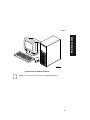
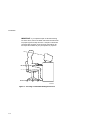

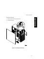
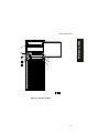
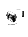
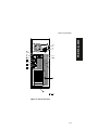
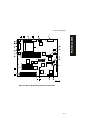
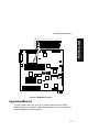
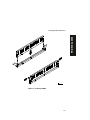
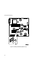
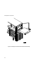
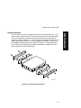
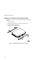
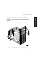
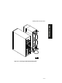
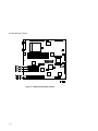
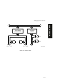

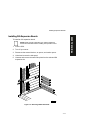
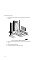
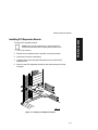

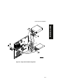
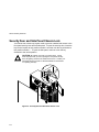

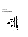
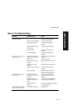
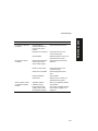
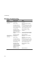
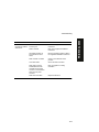
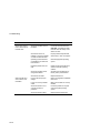
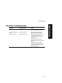
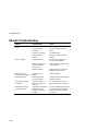
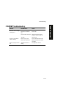


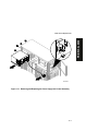

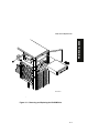
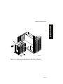
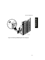
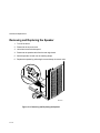
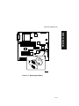
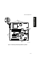
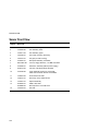
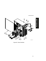
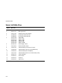
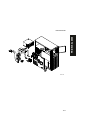

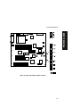
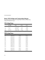

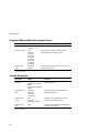
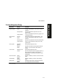
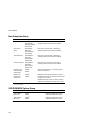
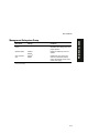
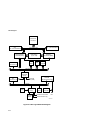


![VPC-1000 MANUAL [20090528]](http://vs1.manualzilla.com/store/data/005896865_1-4751a76ac00044adb338105a42e32db2-150x150.png)