1
SAMSUNG
SMG-3200
SAMSUNG MEDIA GATEWAY
USER GUIDE
Publication Information
Samsung Telecoms reserves the right without prior notice to revise information in this publication for any reason.
Samsung Telecoms also reserves the right without prior notice to make
changes in design or components of equipment as engineering and manufacturing may warrant.
Disclaimer
Samsung Telecoms is not responsible for errors or problems arising from
customers not installing, programming or operating their Samsung systems as described in this manual.
Copyright 2002
Samsung Telecoms (U.K.) Limited
All rights reserved. No part of this manual may be reproduced in any form
or by any means – graphic, electronic or mechanical, including recording,
taping, photocopy or information retrieval system – without express written permission of the publisher of this material.
Part No.:16320
Version 1.0
EU Declaration of Conformity (LVD,EMC)
For the following product:
Product Name: VoIP Media Gateway
Model Name: SMG-3200
Manufactured at:
Factory Name, Address: Samsung Electronics Co., Ltd, 259 Gongdan-Dong, Gumi-City Kyungbuk,
Korea 730-030
We hereby declare that all major safety requirements concerning the CE Marking Directive [93/68/EEC] and
Low Voltage Directive [73/23/EEC], ElectroMagnetic Compatibility [89/336/EEC], amendments [92/31/EEC]
are fulfilled, as laid out in the guidelines set down by the member states of the EEC Commission.
This declaration is valid for all samples that are part of this declaration, which are manufactured according to
the production charts appendix.
The standards relevant for the evaluation of safety & EMC requirements are as follows:
1. Certificate of conformity / Test report issued by:
LVD : EN60950:1992 +A1+A2+A3+A4+A11
EMC : EN55022:1998, EN 61000-3-2:1995 inc+A1+A2:1998,
EN61000-3-3:1995, EN 55024:1998, AS/NZS3548:1995
2. Technical documentation kept at:
LVD: VDE
EMC: SAMSUNG Electronics EURO Q.A. Lab. in the U.K.
which will be made available upon request.
Samsung Electronics Co., Ltd
(Manufacturer)
Samsung Electronics Co., Ltd,
259 Gongdan-Dong, Gumi-City
Kyungbuk, Korea 730-030
2002-03-14
TE Jang
(place and date of issue)
Tae-eok Jang / General Manager
(name and signature of authorised person)
(Representative in the EU)
Samsung Electronics Euro QA Lab.
Blackbushe Business Park
Saxony Way, Yateley, Hampshire
GU46 6GG, UK
2002-03-18
IS Lee
(place and date of issue)
In-Seop Lee / Senior Manager
(name and signature of authorised person)
i
Before You Begin
This guide is intended for anyone who installs and uses the SMG-3200. It provides an introduction
to the SMG-3200 system as well as network setup and maintenance.
Both the novice and expert user in switching systems should first read this guide before
installing the SMG-3200 system, and pay particular attention to the precautionary notes.
This guide describes in detail the structure and the installation of the SMG-3200 system with
illustrations to assist you.
Caution: Fatal problems, such as the loss of significant data or network service disconnection, may occur
if you make modifications to the hardware and board configurations other than those described
in this manual. If you have any inquiries or find any faults with the system, please contact your
system supplier.
ii
About This Guide
This guide comprises seven chapters and three appendices. It explains the functions and features of
the system, and describes installation procedures. It is organized so that you can easily access
information by topic of your choice.
It is best to read this guide from the beginning to the end for safe installation of the SMG-3200.
Summaries of the chapters and appendices follow.
Chapter 1,
Overview describes the various functions of the system, and lists the advantages of
the system.
Chapter 2,
System Boards explains the board types and board features.
Chapter 3,
Installing the System provides instructions for installing the system, placing the
boards in the slots, and connecting the cables to the system.
Chapter 4,
Configuring the System shows how to set up the basic information to use the
system.
Chapter 5,
CLI (Command Line Interface) describes the CLI that enables operational settings
for the SMG-3200. An overview of menus followed by the functions of each menu and
settings of submenus are given.
Chapter 6,
Web-based Remote Management explains how to log in to the web management
interface of the SMG-3200.
Chapter 7,
Using the CDR (Call Detail Record) explains how to view or receive the call
information through the CDR which is provided by the SMG-3200 system.
Appendix A, Call Termination Code describes the form of Call Termination Code and code
information.
Appendix B, System Information (DataBase) File Structure provides the hierarchy and usage of
the text file which enables backup, restore, and editing of SMG-3200 system
information.
Appendix C, Glossary provides definitions of terms used in this guide.
iii
Table of Contents
Chapter 1 Overview · · · · · · · · · · · · · · · · · · · · · · · · · · · · · · ·
1-1
Introduction to SMG-3200 · · · · · · · · · · · · · · · · · · · · · · · · · · · · · · · · ·
1-1
SMG-3200 Features· · · · · · · · · · · · · · · · · · · · · · · · · · · · · · · · ·
1-2
Components of SMG-3200 · · · · · · · · · · · · · · · · · · · · · · · · · · · · · · · ·
1-4
Front View of SMG-3200 · · · · · · · · · · · · · · · · · · · · · · · · · · · · · ·
Rear View of SMG-3200 · · · · · · · · · · · · · · · · · · · · · · · · · · · · · ·
1-4
1-5
SMG-3200 System Specifications · · · · · · · · · · · · · · · · · · · · · · · · · · · ·
1-6
Hardware Specifications · · · · · · · · · · · · · · · · · · · · · · · · · · · · · ·
Software Specifications · · · · · · · · · · · · · · · · · · · · · · · · · · · · · · ·
1-6
1-7
VoIP Network Configuration Using SMG-3200 · · · · · · · · · · · · · · · · · · · ·
1-8
Tandem Gateway Mode· · · · · · · · · · · · · · · · · · · · · · · · · · · · · · ·
Standalone Gateway Mode· · · · · · · · · · · · · · · · · · · · · · · · · · · · ·
1-8
1-9
Chapter 2 System Boards · · · · · · · · · · · · · · · · · · · · · · · · · ·
2-1
Types of Boards · · · · · · · · · · · · · · · · · · · · · · · · · · · · · · · · · · · · ·
Common Boards · · · · · · · · · · · · · · · · · · · · · · · · · · · · · · · · · ·
Universal Boards · · · · · · · · · · · · · · · · · · · · · · · · · · · · · · · · · ·
2-1
2-1
Common Boards · · · · · · · · · · · · · · · · · · · · · · · · · · · · · · · · · · · · ·
MGCB Board · · · · · · · · · · · · · · · · · · · · · · · · · · · · · · · · · · · ·
VOIP Board · · · · · · · · · · · · · · · · · · · · · · · · · · · · · · · · · · · · ·
2-2
2-8
Universal Boards · · · · · · ·
LOOP Board· · · · · · · · · ·
E&M Board · · · · · · · · · ·
SLC Board · · · · · · · · · · ·
2-1
2-2
· · · · · · · · · · · · · · · · · · · · · · · · · · · · ·
2-11
· · · · · · · · · · · · · · · · · · · · · · · · · · ·
· · · · · · · · · · · · · · · · · · · · · · · · · · ·
· · · · · · · · · · · · · · · · · · · · · · · · · · ·
2-11
2-12
2-15
Chapter 3 Installing the System · · · · · · · · · · · · · · · · · · · · · · 3-1
Procedures on Installing the System · · · · · · · · · · · · · · · · · · ·
3-1
Condition of the Installation Location
Space Condition · · · · · · · · · · · · · ·
Grounding Condition · · · · · · · · · · · ·
Input Power Condition · · · · · · · · · · ·
Line Condition · · · · · · · · · · · · · · · ·
3-2
3-3
3-4
3-4
· · · · · · · · · · · · · · · · · · · · · ·
·
·
·
·
·
·
·
·
·
·
·
·
·
·
·
·
·
·
·
·
·
·
·
·
·
·
·
·
·
·
·
·
·
·
·
·
·
·
·
·
·
·
·
·
·
·
·
·
·
·
·
·
·
·
·
·
·
·
·
·
·
·
·
·
·
·
·
·
·
·
·
·
·
·
·
·
·
·
·
·
3-2
Unpacking the System · · · · · · · · · · · · · · · · · · · · · · · · · · · · · · · · ·
3-5
Installing in a Rack · · · · · · · · · · · · · · · · · · · · · · · · · · · · · · · · · · ·
3-6
iv
Safety Precautions ·
Rack Requirements
Required Tools · · ·
Installing in a Rack ·
·
·
·
·
·
·
·
·
·
·
·
·
·
·
·
·
·
·
·
·
·
·
·
·
·
·
·
·
·
·
·
·
·
·
·
·
·
·
·
·
·
·
·
·
·
·
·
·
·
·
·
·
·
·
·
·
·
·
·
·
·
·
·
·
·
·
·
·
·
·
·
·
·
·
·
·
·
·
·
·
·
·
·
·
·
·
·
·
·
·
·
·
·
·
·
·
·
·
·
·
·
·
·
·
·
·
·
·
·
·
·
·
·
·
·
·
·
·
·
·
·
·
·
·
·
·
·
·
Connecting Ground Cable · · · · · · · · · · · · · · · · · · · · · · · · · · · · · · · ·
Installing Boards · · · · · · · ·
System Slots · · · · · · · · ·
Selecting Boards · · · · · · ·
Setting Jumper and Switch ·
Installing Daughter Boards ·
Installing Board in a Slot · ·
3-6
3-7
3-7
3-8
3-9
· · · · · · · · · · · · · · · · · · · · · · · · · · · · ·
3-10
·
·
·
·
·
·
·
·
·
·
3-10
3-11
3-12
3-13
3-16
Connecting Cables · · · · · · · · · · · · · · · · · · · · · · · · · · · · · · · · · · · ·
3-18
Attaching Ferrite Cores · · · · · · · · · · · · · · · · · · · · · · · · · · · · · · · · ·
3-21
Connecting Power Cable · · · · · · · · · · · · · · · · · · · · · · · · · · · · · · · ·
3-21
·
·
·
·
·
·
·
·
·
·
·
·
·
·
·
·
·
·
·
·
·
·
·
·
·
·
·
·
·
·
·
·
·
·
·
·
·
·
·
·
·
·
·
·
·
·
·
·
·
·
·
·
·
·
·
·
·
·
·
·
·
·
·
·
·
·
·
·
·
·
·
·
·
·
·
·
·
·
·
·
·
·
·
·
·
·
·
·
·
·
·
·
·
·
·
·
·
·
·
·
·
·
·
·
·
·
·
·
·
·
·
·
·
·
·
·
·
·
·
·
·
·
·
·
·
Chapter 4 Configuring the System · · · · · · · · · · · · · · · · · · · · 4-1
Setting up the Terminal · · · · · · · · · · · · · · · · · · · · · · · · · · · · · · · · · ·
Terminal Features · · · · · · · · · · · · · · · · · · · · · · · · · · · · · · · · ·
4-1
Starting SMG-3200 · · · · · · · · · · · · · · · · · · · · · · · · · · · · · · · · · · · ·
Turning on · · · · · · · · · · · · · · · · · · · · · · · · · · · · · · · · · · · · · ·
Logging in · · · · · · · · · · · · · · · · · · · · · · · · · · · · · · · · · · · · · ·
4-3
4-4
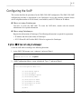
Configuring the Operating Environment · · ·
Configuring the TCP/IP · · · · · · · · · · · · · ·
Configuring the System Operation Mode · · · ·
Configuring the VoIP · · · · · · · · · · · · · · · ·
· · · · · · · · · · · · · · · · · ·
· · · · · · · · · · · · · · · ·
· · · · · · · · · · · · · · · ·
· · · · · · · · · · · · · · · ·
4-1
4-3
4-6
4-6
4-11
4-17
Chapter 5 CLI (Command Line Interface)· · · · · · · · · · · · · · · 5-1
Menu Configuration · · · · · · · · · · · · · · · · · · · · · · · · · · · · · · · · · · · ·
5-1
Using Menus· · · · · · · · · · · · · · · · · · · · · · · · · · · · · · · · · · · · · · · ·
5-3
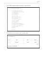
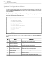
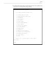
System Configuration Menu · ·
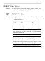
[0]DHCP Client Setting · · · · · ·
[1] Network Configuration · · · · ·
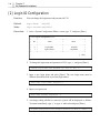
[2 Login ID Configuration · · · · ·
[3] System Upgrade · · · · · · · ·
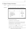
[4] Display Package Information ·
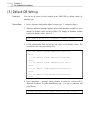
[5] Default DB Setting · · · · · · ·
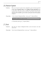
[6] Restart System · · · · · · · · ·
· · · · · · · · · · · · · · · · · · · · · · · · · · ·
·
·
·
·
·
·
·
·
·
·
·
·
·
·
·
·
·
·
·
·
·
·
·
·
·
·
·
·
·
·
·
·
·
·
·
·
·
·
·
·
·
·
·
·
·
·
·
·
·
·
·
·
·
·
·
·
·
·
·
·
·
·
·
·
·
·
·
·
·
·
·
·
·
·
·
·
·
·
·
·
·
·
·
·
·
·
·
·
·
·
·
·
·
·
·
·
·
·
·
·
·
·
·
·
·
·
·
·
·
·
·
·
·
·
·
·
·
·
·
·
·
·
·
·
·
·
·
·
·
·
·
·
·
·
·
·
·
·
·
·
·
·
·
·
·
·
·
·
·
·
·
·
·
·
·
·
·
·
·
·
·
·
·
·
·
·
·
·
5-4
5-5
5-6
5-8
5-9
5-11
5-12
5-13
v
[7] Exit · · · · · · · · · · · · · · · · · · · · · · · · · · · · · · · · · · · · · · · ·
5-13
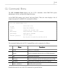
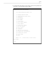
PSTN Configuration Menu · ·
[0] Gateway Operation Mode · ·
[1] PSTN Rerouting Insert Digit
[2] PCM Method · · · · · · · · ·
[3] Dial Method · · · · · · · · · ·
[4] SLC Signal · · · · · · · · · · ·
[5] Trunk Signal · · · · · · · · · ·
[6] Call Control Method · · · · ·
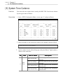
[7] Ring Cadence · · · · · · · · ·
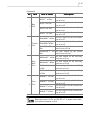
[8] System Tone Cadence· · · ·
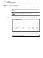
[9] CO Tone Cadence · · · · · ·
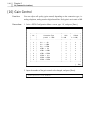
[10] Gain Control · · · · · · · · ·
[11] Diagnosis · · · · · · · · · · ·
[12] MMC Port Block/UnBlock ·
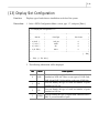
[13] Display Slot Configuration ·
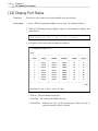
[14] Display Port Status · · · · ·
[15] Save & Exit· · · · · · · · · ·
[16] Exit· · · · · · · · · · · · · · ·
· · · · · · · · · · · · · · · · · · · · · · · · · · ·
5-14
·
·
·
·
·
·
·
·
·
·
·
·
·
·
·
·
·
5-16
5-19
5-20
5-21
5-23
5-24
5-28
5-30
5-32
5-34
5-36
5-38
5-39
5-41
5-42
5-44
5-44
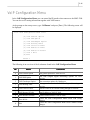
VoIP Configuration Menu ·
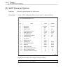
[0] VoIP General Option · · ·
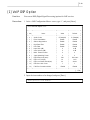
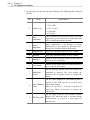
[1] VoIP DSP Option · · · · ·
[2] VoIP Gatekeeper Option
[3] VoIP Routing Table · · · ·
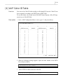
[4] VoIP Caller ID Table · · ·
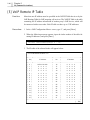
[5] VoIP Remote IP Table · ·
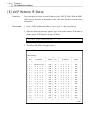
[6] VoIP Remote IP Status ·
[7] Save & Exit · · · · · · · ·
[8] Exit · · · · · · · · · · · · ·
·
·
·
·
·
·
·
·
·
·
·
·
·
·
·
·
·
·
·
·
·
·
·
·
·
·
·
·
·
·
·
·
·
·
·
·
·
·
·
·
·
·
·
·
·
·
·
·
·
·
·
·
·
·
·
·
·
·
·
·
·
·
·
·
·
·
·
·
·
·
·
·
·
·
·
·
·
·
·
·
·
·
·
·
·
·
·
·
·
·
·
·
·
·
·
·
·
·
·
·
·
·
·
·
·
·
·
·
·
·
·
·
·
·
·
·
·
·
·
·
·
·
·
·
·
·
·
·
·
·
·
·
·
·
·
·
·
·
·
·
·
·
·
·
·
·
·
·
·
·
·
·
·
·
·
·
·
·
·
·
·
·
·
·
·
·
·
·
·
·
·
·
·
·
·
·
·
·
·
·
·
·
·
·
·
·
·
·
·
·
·
·
·
·
·
·
·
·
·
·
·
·
·
·
·
·
·
·
·
·
·
·
·
·
·
·
·
·
·
·
·
·
·
·
·
·
·
·
·
·
·
·
·
·
·
·
·
·
·
·
·
·
·
·
·
·
·
·
·
·
·
·
·
·
·
·
·
·
·
·
·
·
·
·
·
·
·
·
·
·
·
·
·
·
·
·
·
·
·
·
·
·
·
·
·
·
·
·
·
·
·
·
·
·
·
·
·
·
·
·
·
·
·
·
·
·
·
·
·
·
·
·
·
·
·
·
·
·
·
·
·
·
·
·
·
·
·
·
·
·
·
·
·
·
·
·
·
·
·
·
·
·
·
·
·
·
·
·
·
·
·
·
·
·
·
·
·
·
·
·
·
·
·
·
·
·
·
·
·
·
·
·
·
·
·
·
·
·
·
·
·
·
·
·
·
·
·
·
·
·
·
·
·
·
·
·
·
·
·
·
·
·
·
·
·
·
·
·
· · · · · · · · · · · · · · · · · · · · · · · · · · · · ·
5-45
·
·
·
·
·
·
·
·
·
·
·
·
·
·
·
·
·
·
5-46
5-49
5-52
5-55
5-59
5-60
5-62
5-64
5-64
CLI Command Menu· · · · · · · · · · · · · · · · · · · · · · · · · · · · · · · · · ·
5-65
·
·
·
·
·
·
·
·
·
·
·
·
·
·
·
·
·
·
·
·
·
·
·
·
·
·
·
·
·
·
·
·
·
·
·
·
·
·
·
·
·
·
·
·
·
·
·
·
·
·
·
·
·
·
·
·
·
·
·
·
·
·
·
·
·
·
·
·
·
·
·
·
·
·
·
·
·
·
·
·
·
·
·
·
·
·
·
·
·
·
·
·
·
·
·
·
·
·
·
·
·
·
·
·
·
·
·
·
·
·
·
·
·
·
·
·
·
·
·
·
·
·
·
·
·
·
·
·
·
·
·
·
·
·
·
·
·
·
·
·
·
·
·
·
·
·
·
·
·
·
·
·
·
·
·
·
·
·
·
·
·
·
·
·
·
·
·
·
·
·
·
·
·
·
·
·
·
·
·
·
·
·
·
·
·
·
·
·
·
·
·
·
·
·
·
·
·
·
·
·
·
·
·
·
·
·
·
·
·
·
·
·
·
·
·
·
·
·
·
·
·
·
·
·
·
Chapter 6 Web-based Remote Management · · · · · · · · · · · · · · · · 6-1
Before you Begin· · · · · · · · · · · · · · · · · · · · · · · · · · · · · · · · · · · · ·
6-1
Login · · · · · · · · · · · · · · · · · · · · · · · · · · · · · · · · · · · · · · · · · · · · ·
6-1
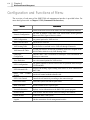
Configuration and Functions of Menu · · · · · · · · · · · · · · · · · · · · · ·
6-4
vi
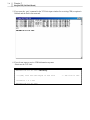
Chapter 7 Using the CDR (Call Detail Record) · · · · · · · · · · 7-1
Screen for checking current call information · · · · · · · · · · · · · · ·
7-1
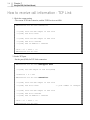
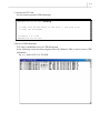
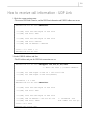
How to receive call information - TCP Link · · · · · · · · · · · · · · · ·
7-2
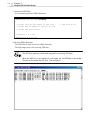
How to receive call information - UDP Link · · · · · · · · · · · · · · · ·
7-5
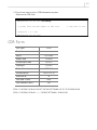
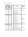
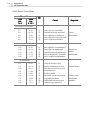
CDR Form· · · · · · · · · · · · · · · · · · · · · · · · · · · · · · · · · · · · · · · · · · · 7-7
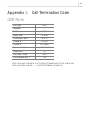
Appendix A Call Termination Code · · · · · · · · · · · · · · · · · · · · A-1
CDR Form · · · · · · · · · · · · · · · · · · · · · · · · · · · · · · · · · · · · · · · ·
A-1
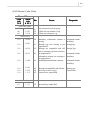
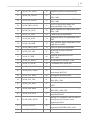
Call Termination Code · · · · · · · · · · · · · · · · · · · · · · · · · · · · · · · · · A-2
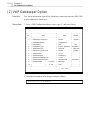
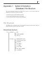
Appendix B System Information (Database)
File Structure · · · · · · · · · · · · · · · · · · · · · · · · · · B-1
File Structure · · · · · · · · · · · · · · · · · · · · · · · · · · · · · · · · · · · · · · B-1
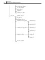
Hierarchical structure · · · · · · · · · · · · · · · · · · · · · · · · · · · · · · B-1
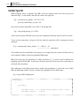
Syntax structure · · · · · · · · · · · · · · · · · · · · · · · · · · · · · · · · · B-3
Appendix C Glossary · · · · · · · · · · · · · · · · · · · · · · · · · · · · · · · C-1
1-1
Chapter 1 Overview
This chapter describes the various functions of the SMG-3200 system, its component parts, and
system specifications to provide you with a good understanding of the system.
Introduction to the SMG-3200
SMG-3200 VoIP (Voice over Internet Protocol) gateway system is a high performance H.323
compliant gateway optimized for voice communication over the Internet.
SMG-3200 enables transmission of both voice and FAX data from a PSTN (Public Switched
Telephone Network) through real-time data compression and protocol conversion. Therefore, it
enables seamless integration of voice and data networks, simple network architecture design and
considerable cost reduction in network infrastructure construction. Also, it can provide longdistance and international telephone services at local telephone rates for users in an Internet or
Intranet environment.
Since SMG-3200 is designed based on hardware and software modules, it is easy to install.
Installation of trunks, subscriber lines or new software for additional features is possible, even during
operation if necessary.
SMG-3200 provides local/remote CLI (Command Line Interface). To use SMG-3200 after
installing the hardware, only a basic information configuration for system operation using CLI
commands is needed, while the remaining operating environment configuration is automatically
configured using default values. Providing conversational type CLI, SMG-3200 enables easier
system configuration even if a user is not accustomed to the Gateway system.
1-2
Chapter 1
Overview
SMG-3200 Features
The SMG-3200 system has the following major features.
PSTN Interfaces
The SMG-3200 system provides the following PSTN interfaces for interoperability with PSTN.
LOOP Analog Tr unk Interface
E1/PRI, T1 Digital Station Interface (PBX, KTS Interface)
E&M Analog Station Interface (PBX, KTS Interface)
SLC Analog Interface
VoIP Interfaces
VoIP is a technology that enables simultaneous transmission of both voice and data over the
Internet, and enables Internet telephony service. The SMG-3200 system offers the following VoIP
interfaces.
H.323-V3 VoIP Interface
Gatekeeper Interface (RAS)
Real Time Internet Fax Support (FoIP)
Trunk Routing Functions
The SMG-3200 system offers the following trunk functions including trunk routing, trunk tandem,
and access code control.
Trunk Routing
Ÿ LCR (Lease Cost Routing) code and route control
Ÿ Dynamic rerouting depending on the traffic load of PSTN and Internet Protocol state
Ÿ Routing Table
Trunk Tandem
Ÿ Various PSTN and VoIP trunks connection
Ÿ Interoperability among analog trunk, digital station, and VoIP network
1-3
Access Code Control
Ÿ IP address translation based on access code and prefix number
Call Processing Functions
The SMG-3200 system provides the following call processing functions.
R2 Signaling and DTMF Signaling
Caller ID Relay between PSTN and VoIP
DTMF Relay between PSTN and VoIP
CDR (Call Detail Record) Generation
RTP Traffic Channel Status Monitoring Functions (Delay, Loss, and Link Down)
System Management Functions
The SMG-3200 system provides a GUI interface, and a Standard Network Management Protocol
(SNMP) for easier management. The SMG-3200 also provides the following system management
functions.
Web-based Management
Program change by TFTP Loading
DHCP Client (IP address allocation by DHCP server)
FTP, Telnet Interface
CLI (Command Line Interface)
1-4
Chapter 1
Overview
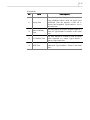
Components of SMG-3200
This section explains each component and function of the SMG-3200 system.
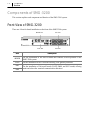
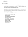
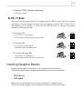
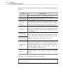
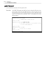
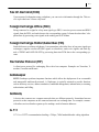
Front View of SMG-3200
There are 4 slots for board installation on the front of the SMG-3200 system.
Slot
MGCB
VOIP
US1
US2
MGCB Slot
US1 Slot
VOIP Slot
US2 Slot
Description
For the installation of the MGCB board that controls overall operation of the
SMG-3200 system.
For the i nstallation of the VoIP board offering VoIP gateway functions.
For the installation of Universal boards (LOOP, E&M, and SLC boards) offering
trunk and subscriber terminal communication functions.
1-5
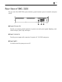
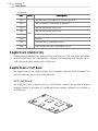
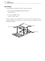
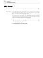
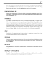
Rear View of SMG-3200
The rear side of the SMG-3200 system includes a ground terminal, power-in terminal, and power
switch.
¶Ground Connector
Provides an external ground connection to protect user and system against lightning, static
electric charges, spikes, sags, and surges.
·Power Connector
Provides power supply cable connection. It requires AC 110-240V main power.
¸Power Switch
A switch to turn the system power on/off.
1-6
Chapter 1
Overview
SMG-3200 System Specifications
This section describes hardware and software specifications of the SMG-3200 system.
Hardware Specifications
Feature
Processor
Description
MPC860 50MHz
Ÿ Boot Flash ROM : 512KB
Memory
Ÿ Flash Memory : 8MB
Ÿ SDRAM : 16MB
System
VoIP DSP
2 ~ 8 of Audio Codes AC4804
Network
10Base-T/100 Base-TX
Test Port
RS-232C
Power
Analog
Ÿ Input : AC 110-240V
Ÿ Output : -48V(25W), +5V(10W), +3.3V(15W)
Ÿ Loop : 8/16 Channel
Ÿ SLC : 8/16 Channel
Ÿ E&M : 8/16 Channel
Ÿ T1 : 24 Channel
Ÿ E1 : 30 Channel
Line Capacity
Digital
Ÿ PRI : 30 Channel
Ÿ R2 : 8 Channel
VoIP
Ÿ DTMF : 4 Channel
Ÿ 8/16/24/32 Channel
- G.723.1, G.729A,G.711
- Fax channel receives maximum of 8 channels.
- Fax channel receives maximum of 6 channels when
G.711 codec is used.
1-7
Software Specifications
Feature
Description
OS
VxWorks
VoIP Protocol
ITU-T H.323-V3
VoIP Codec
G.723.1, G.729A, G.711
Ÿ Echo Cancellation (G.165)
Ÿ Silence Suppression (VAD, CNG)
Audio Function
Ÿ DTMF Detection/Generation(In/Outband)
Ÿ Selectable A / u law
Ÿ Gain/Volume Control
Ÿ Dynamic Jitter Control
Ÿ H.323-V3 Interoperability (RADVision)
Ÿ G3 Internet FAX Relay (FRF.11, T.38)
Ÿ External Gatekeeper RAS Interface
VoIP Function
Ÿ Internal Gatekeeper Functions (Control Code Translate/Add/Delete)
Ÿ Flexible Numbering Plan
Ÿ Caller ID (G/W ID, IP, ANI, Assigned Caller ID )
Ÿ QoS Functions (Delay/ Loss/Link Down Check, RTP Multiframe, IP TOS)
Ÿ DHCP Client Functions to Enable Automatic IP Address Allocation
Ÿ Remote Program Upgrade
Ÿ FTP, TFTP, Telnet Network Interface
System
Management
Ÿ Easy Install (Default Configuration)
Ÿ Diagnostic and Alarm Report
Ÿ Local/Network CLI Interface
Ÿ System Maintenance Through NMS Manager Center
- GUI, SNMP, Web Management
- DB List and Change
1-8
Chapter 1
Overview
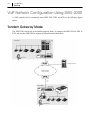
VoIP Network Configuration Using SMG-2000
A VoIP network can be constructed using SMG-3200, PBX, and KTS as the following figure
shows.
Tandem Gateway Mode
The SMG-3200 can be run in the tandem gateway mode. It connects the SMG-3200 to PBX or
KTS, and uses the SMG-3200 as a gateway without internal subscribers.
1-9
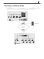
Standalone Gateway Mode
The SMG-3200 can be run in the standalone gateway mode. It connects a telephone to an SLC port
on the SMG-3200 and uses the system as a VoIP Gateway with internal subscribers.
2-1
Chapter 2 System Boards
This Chapter describes the types of boards available for the SMG-3200, and the functions and
features of each board.
Types of Boards
There are two types of boards available for the SMG-3200.
Common Boards
Common boards have to be installed in the SMG-3200 system. They provide important
functions such as operational control of the system, and VoIP gateway functions. Common
boards include the following two boards.
*MGCB (Media Gateway Control Board) board
*VOIP (Voice over Internet Protocol) board
Universal Boards
Universal board may be installed depending on the user’s need. US1 and US2 system slot is
intended for Universal boards. Universal boards include the following three boards.
*LOOP (Loop Start Trunk) board
*E&M (E&M Tie Trunk Module) board
*SLC (Subscriber Line Circuit) board
2-2
Chapter 2
System Boards
Common Boards
Common boards of the SMG-3200 system include the MGCB board and VOIP board. This section
describes the features of each board.
MGCB Board
MGCB (Media Gateway Control Board) board controls the entire operation of the SMG-3200
system, and is installed in the MGCB system slot.
Three memories are installed in the MGCB board.
*512KB Flash Memory : Booting program is stored.
*8MB Flash Memory : Database used by the SMG-3200 system is saved in.
*16MB SDRAM : The place where the system software is run.
The features and functions of the MGCB board are as follows.
y Operational control of installed boards in the system
y Detection and generation of 16 DTMF
y Generation of 7 call progressing tones
y Offering 256x256 channel time slot
y Providing digital station interfaces and R2 signaling
y Offering a 10/100Mbps LAN port, and RS232C port
2-3
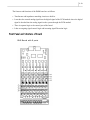
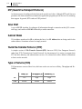
Front Panel and Structure of Board
There are E1/PRI, T1 ports, LAN port, RS-232C port, and system status LEDs on the MGCB
board. There are 8 DIP switches on the board.
S7
S6
S8
6
S3
S5
S1
S2
S4
7
L1
MGCB
E1/T1/PRI
1
LAN
2
PWR OPER E1 E1
SYNC LOS
RS-232C
3
LAN LAN
L2 TX RX
4
❶ E1/PRI, T1 Port (RJ-45): for E1/PRI, T1 station line connection.
❷ LAN Port (RJ-45): for 10/100Mbps Ethernet LAN connection. It is connected to network
equipment such as a hub or switch.
❸ RS-232C Port: for system setup and testing using CLI (Command Line Interface). It is
usually connected to the serial port of a PC.
2-4
Chapter 2
System Boards
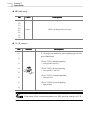
❹ LED Indicators
LED
Color
Description
L1
LED blinks during system initialization.
L2
LED blinks during normal system operation.
PWR
LED is on when power is normally supplied to system.
OPER
LED blinks during system software operation.
Green
LAN TX
LED blinks during data transmission through LAN port.
LAN RX
LED blinks during data reception through LAN port.
E1 SYNC
LED is on if D-TRK clock synchronization fails.
E1 LOS
LED is on if D-TRK signal is missing.
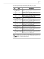
r DIP Switch
Switch
Default
S1
OFF
Reserved
S2
OFF
Reserved
S3
OFF
Reserved
S4
OFF
For D-TRK clock signal input, set to ON. Set to ON state during
an offline test (used in factory)
S5
OFF
For D-TRK signal data input, set to ON.
ON
OFF
1, 2 : BPS
0, 1 : 8bit operation
ON
3 : IP
0 : MSR[IP] initial value is one
OFF
4 : EARP
0 : Internal operation
S6
S7
S8
OFF
ON
OFF
OFF
ON
ON
ON
ON
Description
Reserved.
3, 4 : ISB
1, 0 : Base address 0xFF000000
Reserved.
3, 4 : DBPC
0, 0 :
Debug Port Configuration
2-5
If you change the S6,S7,S8 , the SMG-3200 system doesn’t work normally.
R2 Board Installation Slot
This slot is intended for the installation of the R2 board, a daughter board of the MGCB board.
You can find detailed information about the R2 board in the following section.
E1/PRI, T1 Board Installation Slot
This slot is intended for the installation of the E1/PRI, T1 board, a daughter board of the
MGCB board. You can find detailed information about the E1/PRI, T1 board in the following
section.
Daughter Boards of MGCB Board
Daughter boards of MGCB board include the E1/PRI, T1 board and R2 board. This section
describes the features of each daughter board.
R2 Board
The R2 board provides and 8 channels R2 signaling through a digital trunk (E1).
E1/PRI, T1 Board
The E1/PRI, T1 board provides interfaces to connect E1, ISDN PRI, or T1 station lines to an
SMG-3200 system.
Configuring DIP switch and jumper executes the software for E1 or ISDN PRI service
automatically. T1 board is also setup automatically by software when installed.
The E1 is a high-speed digital line with a data transmission rate of 2.048Mbps. The E1 offers 32
separated communication channels. 30 channels are used for PCM data communication at 64Kbps,
and 2 channels are used for communication signaling.
2-6
Chapter 2
System Boards
The T1 is a high-speed digital line with a data transmission rate of 1.544Mbps. The T1 offers 24
separated communication channels. Each channel is used for PCM data communication at 64Kbps.
The PRI (Primary Rate Interface) includes T1, and E1 type stations, but the SMG-3200 only
provides E1 type PRI. E1 type PRI offers 30B channels and 1D channel (30B+1D). Each channel
provides 64Kbps data communication.
S1
S2
JP1
JP2 JP4
JP3 JP5
❶ DIP Switch
Switch
Description
S1 and S2 switches are intended to select Card ID according to the line type
connected to the E1/PRI, T1 board.
S1
S2
y To connect E1,
☞ Set both S1 and S2 switches to ON.
y To connect T1,
☞ Set S1 switch to ON, and set S2 switch to OFF.
y To connect E1 type PRI,
☞ Set S1 switch to OFF, and set S2 switch to ON.
2-7
❷ JP1 ~ JP5 Jumper
Jumper
JP1
JP2
JP3
JP4
JP5
Description
JP1~JP5 jumpers are intended to specify impedance mapping according to the
type of line to be connected to the E1/PRI, T1 board.
y To connect E1,
☞ Close pin #2-3 of all jumpers.
y To connect T1,
☞ Close pin #1-2 of all jumpers.
y To connect E1 type PRI,
☞ Close pin #2-3 of all jumpers.
2-8
Chapter 2
System Boards
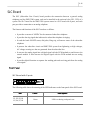
VOIP Board
The VOIP board performs conversion of the voice data of PSTN into packet data that can be
transmitted over IP networks. In other words, it provides H.323 V3-complient VoIP Gateway
functions to enable voice communication over the Internet. The VOIP board of the SMG-3200
system comes in a VOIP board with 8 Internet telephone channels.
On the VOIP board with 8 Internet telephone channels, up to 3 VOIP_Sub boards can be installed,
and each VOIP_Sub board provides 8 Internet telephone channels. As a result, besides the 8
Internet telephone channels of the VOIP board, a maximum of 24 additional Internet telephone
channels can be installed on a board.
The features and functions of the VOIP board are as follows.
y G.729A, G.723.1, G.711 audio codec support
y Internet FAX support
y Caller ID detection and generation function
y FAX/data auto-detection
y G.165 compliance, 16ms echo canceler
y DTMF detection and generation function
y u-Law/A-Law support
y Input/Output Gain Control
y VAD/CNG support
2-9
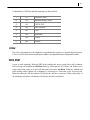
Front Panel and Structure of Board
There are LEDs indicating VOIP board status on the front panel of the VOIP board.
VOIP Board With 8 Channels
2
Loc1
2
2
Loc2
2
2
Loc3
2
8CH 24CH LD1 LD3 LD5 LD7
VOIP
16CH 32CH LD2 LD4 LD6 LD8
❶ LED Indicators
LED
Color
8CH
LED is on when VOIP board is installed in system slot.
16CH
24CH
32CH
Description
LED is on when the first daughter board is installed on VOIP board.
Green
LED is on when the second daughter board is installed on VOIP
board.
LED is on when the third daughter board is installed on VOIP board.
2-10
Chapter 2
System Boards
(Continued)
LED
Color
Description
LD1
LED blinks when VoIP software is in normal operation.
LD2
LED is on when it is connected with gatekeeper.
LD3
LED is on when major alarm occurs.
LED is on when minor alarm occurs.
LD4
Green
LD5
Reserved.
LD6
Reserved.
LD7
LED blinks during VoIP channel service.
LD8
LED is on when the entire VoIP channel is in use.
Daughter Board Installation Slots
Daughter board installation slot is dedicated to the installation of a VOIP_Sub board, the daughter
board of a VOIP board. The VOIP board has 3 daughter board installation slots. Therefore, up to 3
VOIP_Sub boards can be installed on the VOIP board.
Daughter Board of VoIP Board
The daughter board of the VOIP board that can be installed is called the VOIP_Sub board. This
section describes the features of the VOIP_Sub board.
VOIP_Sub Board
The VOIP_Sub board is daughter board for VoIP channel extension, and provides 8 Internet
telephone channels. A maximum of 24 additional Internet telephone channels can be installed on
the VOIP board.
2-11
Universal Boards
The Universal board may be installed in the US1 and US2 slots of the SMG-3200 system
depending on the user’s need. There are two types of Universal boards, trunk board and subscriber
board, which provide different services.
The following table shows the summary of each type of Universal board.
Card Type
Board Name
Trunk Board
Analog Board
LOOP
Subscriber Board
Analog Board
E&M
SLC
In the following sections, detailed information about features, functions, front panel, and jumper
settings for each type of Universal board will be presented.
LOOP Board
The LOOP (Loop Start Trunk) board provides the local extension trunk interface, and can be
installed in the universal slot (US1, US2) of a system. The LOOP board for the SMG-3200 system
comes in a LOOP board with 8 ports. It provides a connection to a private branch exchange (PBX),
or the local telephone office.
The features and functions of the LOOP board are as follows.
y It provides the signal detection function.
y Impedance matching circuits are built in.
y It reads the status such as the HOS and Ring Detection, Tone Detection, and Polarity
Reverse Signal etc.
y It converts the analog signal into a digital signal with the PCM method to send them to the
control module. It also converts the digital signal with the PCM method into an analog
signal.
y It protects the SMG-3200 system from lightening or high voltages, AC voltage crossing etc.
2-12
Chapter 2
System Boards
Front Panel
LOOP Board with 8 ports
LOOP
P1
P2
P3
P4
P5
P6
P7
P8
P1
P3
P5
P7
P2
P4
P6
P8
The following table shows the meaning of the LED indicators on the front panel of the LOOP
board.
LED
Color
Description
P1
P2
P3
P4
P5
P6
P7
P8
Green
LED is on during each port in use.
E&M Board
The E&M (E&M Tie Trunk Module) board provides a 4-Wire E&M dedicated line for connection
of SMG-3200 system and private branch exchange (PBX) or key telephone system (KTS), and can
be installed in the universal slot (US1, US2) of a system. The E&M board for the SMG-3200
system comes in an E&M board or 4W E&M board with 8 ports.
The E&M board has two independent voice lines to send and receive the signal where this line is
used as a dedicated line. The sending side consists of a Tip and Ring while the receiving side
consists of a Tip1 and Ring1. Because signal and voice circuits are separated from each other, the
transformer does not need the DC power feeding. The DC signal generated in M-LEAD and also
detects in E-LEAD.
The E&M board is divided into the type 1 E&M and type 2 E&M according to the circuit ground
way. The type1 is used in the case of grounding on the opposite side. The type 2 is used in the case
of grounding on the access side of port.
The E&M board has 2 independent transformers to send/receive voice signal in each port. The
board’s hybrid is used for 4stage control gain in each port where the line interface controller
provides the relay point to control the M-LEAD signal and read/write logic.
2-13
The features and functions of the E&M board are as follows.
y Transformer and impedance matching circuits are built in.
y It encodes the entered analog signal into the digital signal of the PCM method where the digital
signal is decoded into the analog signal on the system through the PCM method.
y There is separate logic to the control port of the board.
y It has an outgoing signal control logic and incoming signal Detection logic.
Front Panel and Structure of Board
E&M Board with 8 ports
2-14
Chapter 2
System Boards
n LED Indicators
LED
Color
P1
P2
P3
P4
P5
P6
P7
P8
Green
Description
LED is on during each port in use.
❷ J1~J8 Jumper
LED
Default
Description
J1~J8 jumpers are intended to select signaling type for each
port of E&M board.
J1
J2
yTo use TYPE I -Standard signaling,
☞ Close pin B-O and C-G.
J3
J4
J5
J6
J7
yTo use TYPE I -Inverted signaling,
☞ Close pin B -C and G-O.
A
B O
C
G
NC
yTo use TYPE II –Standard signaling,
☞ Close pin A-O.
yTo use TYPE II -Inverted signaling,
☞ Open all pins.
J8
If the power of the connected system is not – 48V, open the shunt pin of C-B.
2-15
SLC Board
The SLC (Subscriber Line Circuit) board provides the connection between a general analog
telephone and the SMG-3200 system, and can be installed in the universal slot (US1, US2) of a
system. The SLC board for the SMG-3200 system comes in a SLC board with 8 ports, and each
port provides a connection to an analog telephone.
The features and functions of the SLC board are as follows.
y It provides a current of -48VDC for the connected subscriber telephone.
y It provides the ring signal that indicates the subscriber telephone is ringing.
y It reads the hook ON/OFF status, dial pulse, Ring trip, call answer status of the subscriber
telephone.
y It protects the subscriber circuit and SMG-3200 system from lightening or high voltages,
AC voltage crossing etc. that are generated from the subscriber line.
y It converts the analog signal into a digital signal with the PCM method to send them to the
control module. It also converts the digital signal with the PCM method into an analog
signal.
y It provides hybrid function to separate the sending path and receiving path from the analog
voice signal.
Front Panel
SLC Board with 8 ports
SLC
P1
P2
P3
P4
P5
P6
P7
P8
P1
P3
P5
P7
P2
P4
P6
P8
The following table shows the meaning of the LED indicators on the front panel of the SLC board.
LED
P1, P2, P3, P4
P5, P6, P7, P8
Color
Green
Description
LED is on during each port in use.
3-1
Chapter 3 Installing the System
This chapter provides SMG-3200 system installation procedures. First, step by step SMG-3200
system installation procedures are presented, and then environment configuration, board
installation, and power cable connecting procedures are explained.
Procedures on Installing the System
Following steps must be taken to install the SMG-3200 system.
1. Prepare the place to set up the system.
2. Move the packed system product to the installation place and unpack.
3. Installing in a rack. (Option)
4. Connect the grounding line.
5. Set up the jumper and install the daughter board of the board you want to load.
6. Install the board in a slot.
7. Connect cables.
8. Turn on the system after running a prior checkup.
Here are the detailed explanations of steps one to eight.
3-2
Chapter 3
Installing the System
Condition of the Installation Location
SMG-3200 system can be installed in a rack or on a table. To operate the SMG-3200 system
securely, you have to find the location that satisfies the conditions described in this chapter before
setting up the system.
Please do not place the unit on a table with a table cloth, and do not cover
the ventilation slots.
Space Condition
You have to select the location that satisfies the following conditions such as safety condition and
temperature/humidity condition.
y Installation is to be performed by qualified service personnel only.
y To be installed in Restricted Access Areas.
Safety Condition
y Remove the objects that are sensitive to fires such as explosive gas and flammable objects in the
exchange room.
y Before setting up the system, check that every condition is satisfied such as the power wiring,
grounding, voltage, frequency, and etc.
y If the power switch or circuit breaker is open, be sure to remove the power supply line’s
blocking route.
y If the PSTN is connected with the system, set up the protection element in the MDF.
y If subscriber cable goes outside, set up the protection element in the MDF.
y Place a booklet that provides emergency measures, grate, artificial respiration and heart
resuscitation information in the exchange room to prepare for emergency cases such as electric
shock.
3-3
Temperature/Humidity Condition
y Maintain the consistent temperature and humidity.
*Temperature : 0oC – 45oC
*Humidity : 10% – 90% (non-condensing)
y Should be in a cool place not exposed to direct sunlight.
y During or after setting up the system, equip a fan in the room in order to maintain the system by
preventing dust from going into.
Grounding Condition
You have to consider the followings when performing grounding operation.
y The connection hole, connected with the SMG-3200 grounding conductor, should be connected
to the earth grounding through a fine earth-grounding medium.
y Overall, the power circulation status of the SMG-3200 system exposed electric conduction with
the metal face and the rectifier power plug’s grounding conductor should be exceedingly fine.
y A single contact point must be made to connect if the grounding of all of the exterior
supplementary equipment are connected to the system’s grounding.
y The SMG-3200 grounding conductor should never be connected with the pipe for the interior
power wire.
y Power and ground standard must follow the national standard, and the installation office should
check whether the standard is kept.
y Power and grounding standards should suit the national standard where this are certified by an
installation organization.
3-4
Chapter 3
Installing the System
Input Power Condition
The input power of the SMG-3200 system needs to be supplied with the AC power.
In the SMG-3200 input power, an AC 110-240V should be supplied normal alternating current AC
power.
You should use the consent that supplies normal AC only for the SMG-3200 system. This consent
should not be used parallel with other devices. This consent should be located at a safe place to
prevent cutting off the power by mistake.
You should choose the power outlet suitable for the SMG-3200 capacity.
The standard of the SMG-3200 system is
y Input : AC 110-240V
y Output : -48V(25W), +5V(10W), +3.3V(15W)
Line Condition
You need to take careful note of the following when installing cables.
y When wiring at a place where there is high humidity, take steps to reduce this to acceptable
levels before proceeding with the work.
y Take care of the cable to prevent it from being deformed or damaged.
y Make the line’s curvature radius to be 6 times larger than the cable’s circumference where there
have no repeating curved points.
y You must take extreme precaution in the cable’s insulation overlap cases where the copper wire
are exposed and get entangled.
y The maximum allowable line’s loop resister is not more than 1.8KOhm. The line’s leak resistor
must be over 20KOhm, the earth’s leak resistor must be over 20KOhm. (These conditions may
be ignored only in special cases.)
y Analog and Digital subscribers are recommended to use 24AWG line.
y Do not place the line near a high voltage power line.
3-5
Unpacking the System
After preparing the place to install the SMG-3200 system and finishing all the preparation work by
meeting all the conditions, move the packed SMG-3200 system to the installation location.
Unpack the system and check if all the items are in the shipping carton. Basically, there should be
the following items in the package.
*SMG-3200 system that are separately packed
*Various separately packed boards
*2 Ferrite Core
*Power cable
*SMG-3200 User Guide
And, the remaining items can be different according to the orders. Compare closely the order form
and the items that you have. Please contact the distributor where you had bought the SMG-3200
system if there is any missing item or different item from the order form.
When you use a sharp tool to open the package, the item may be damaged.
Before open the top-cover, please make sure that the main cable is detached
from power line.
Chapter 3
3-6
Installing the System
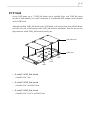
Installing in a Rack
SMG-3200 system can be installed in a rack or on a table. Installation of SMG-3200 in a rack
enables more convenient usage and management. This section provides procedures for SMG-3200
system installation in a rack. For the case of SMG-3200 system installation on a table, skip this
section and refer to the following ‘Connecting Ground Cable’ section.
Safety Precautions
To ensure general safety, always follow these precautions before stalling the SMG-3200 on a rack.
y
Elevated Operating Ambient Temperature- The details should be provided so that
consideration shall be give to installing the equipment in an environment compatible with the
manufacturer’s maximum rated ambient temperature (45°C).
y
Reduced Air Flow- Installation of the equipment in a rack shall be such that the amount of air
flow required for safe operation of the equipment is not compromised.
y
Mechanical Loading- Mounting of the equipment in the rack shall be such that a hazardous
condition is not achieved due to uneven mechanical loading.
y
Circuit Overloading- Consideration should be given to connection of the equipment to the
supply circuit and the effect that overloading circuits may have on overcurrent protection and
supply wiring. Appropriate consideration of the equipment nameplate rating should be used
when addressing this concern.
y
Reliable Earthing- Reliable earthing of the rack mounting equipment should be maintained.
3-7
Rack Requirements
Before installation of SMG-3200 system in a rack, you have to prepare a rack that meets the
following requirements.
y Prepare a rack with standard electrical facilities.
y Ensure that the rack has appropriate ventilators, if it is closed type. A closed type rack should
provide at least one ventilator with fan on the side of the rack in order to circulate cool air into
the rack.
y Pay attention in a closed type rack as the ventilator may cause hot air from the lower system to
rise up to the port opening of a system installed in an upper position in the rack.
y Ensure not to block up the port or fan of installed systems, if the rack is opened type.
y Ensure that the rack is equipped with an internal power bar, and is located near power supply
units.
y Ensure that the rack has ventilators on the side as well as backside for smooth air circulation.
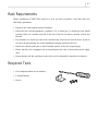
Required Tools
y Cross-shaped medium-size screwdriver
y L-shaped Bracket
y Screws
3-8
Chapter 3
Installing the System
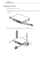
Installing in a Rack
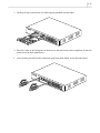
1. Prepare two brackets and six screws.
2. Attach the brackets to each panel of the system by using the screws and fasten them on to the
SMG-3200.
Media
Gatew
ay
MG
SMG
-320
CB
E1/T1
/PR
I
0
LAN
VOIP
L1
RS-23
2C
PWR
4/8CH
16CH
24CH
32CH
LD1
LD2
LAN
TX LAN
RX
L2
OPER
E1
SYNC E1
LOS
LD3
LD4
LD5
LD6
LD7
LOOP
P1
P2
LD8
P3
P4
SLG
P5
P1
P6
P1
P3
P7
P2
P5
P7
P8
P3
P2
P4
P5
P1
P6
P4
P3
P7
P6
P5
P8
P7
P8
P2
P4
P6
P8
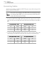
3. By using 4 other screws, install the SMG-3200 unit (with brackets) in a rack.
Med
ia Gat
ewa
y
SMG3200
MG
CB
E1/T1/
PRI
LAN
VOIP
L1
RS-
232
LAN
TX LAN
RX
L2
C
PWR
4/8CH
16CH
24CH
32CH
LD1
LD2
OPER
E1
SYNC E1
LOS
LD3
LD4
LD5
LD6
LD7
LOOP
P1
P2
LD8
P3
P4
P5
SLG
P1
P6
P1
P3
P7
P2
P5
P7
P8
P3
P2
P4
P5
P1
P6
P4
P3
P7
P6
P5
P8
P7
P8
P2
P4
P6
P8
3-9
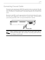
Connecting Ground Cable
The protective earth connection to the SMG-3200 is provided via three core mains lead. The earth
wire in the mains cord (Green/Yellow) is connected in the factory to the earth terminal within the
system. The Earth wire is connected directly to the ground connection on the rear panel of the
system.
The protective earth (PE) is used for surge protection and for the electrical safety of the system.
The system must be plugged into a GPO socket that is correctly earthed. The PE provided all
system earthing requirements, a TRC is not required and should not be connected.
ON(I)
AC 120-240V
OFF(O)
Before connecting ground cable, ensure that AC power supply cable is
disconnected. With power cable connected, connecting ground cable may
cause damage or possibly death.
3-10
Chapter 3
Installing the System
Installing Boards
Before installing or changing the various universal boards, please make sure
that the main cable is detached from power line and that all at telecommunication cables are deltached form telecommunication ports.
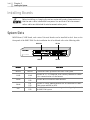
System Slots
MGCB board, VOIP board, and various Universal boards can be installed in the 4 slots on the
front panel of the SMG-3200. For the installation slot of each board refer to the following table.
MGCB Slot
US1 Slot
L1
MGCB
E1/T1/PRI
LAN
RS-232C
LAN LAN
L2 TX RX
PWR OPER E1 E1
SYNC LOS
LOOP
P1
P2
P3
P4
P5
P6
P7
P8
P1
P3
P5
P7
P2
P4
P6
P8
P1
P3
P5
P7
P2
P4
P6
P8
4/8CH 24CH LD1 LD3 LD5 LD7
Media Gateway
SMG-3200
16CH 32CH LD2 LD4 LD6 LD8
VOIP
VOIP Slot
Board
Slot
MGCB
MGCB
VOIP
VOIP
LOOP
E&M
SLC
US1
US2
US1
US2
US1
US2
SLC
P1
P2
P3
P4
P5
P6
P7
P8
US2 Slot
Function
Controls the entire operation of the SMG-3200 system.
Provides H.323 V3-complient VoIP Gateway functions to enable
voice communication over the Internet
Provides the local extension trunk interface.
Provides a 4-Wire E&M dedicated line for connection of SMG3200 system and PBX or KTS.
Provides the connection between a general analog telephone and
the SMG-3200 system
3-11
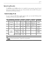
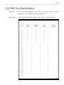
Selecting Boards
The MGCB board and VOIP board have to be installed for system operation, whereas Universal
boards may be installed if desired. The type of Universal board used in the SMG-3200 system is
determined by the following conditions.
Tandem Gateway Mode
In case of using the SMG-3200 in tandem gateway mode, you can install following boards
according to the connection method of PBX or KTS.
No
Connection
1
FXS/FXO
2
FXO
3
E&M
5
6
7
Digital
Station
Interface
MGCB Slot
VoIP Slot
US1 Slot
US2 Slot
MGCB
VOIP (16 ch) SLC (8 ch) LOOP (8 ch)
(-)
(8 ch)
(Incoming)
(Outgoing)
MGCB
VOIP (16 ch) LOOP (8 ch) LOOP (8 ch)
(-)
(8 ch)
(In/Out)
(In/Out)
MGCB
VOIP (16 ch)
E&M (8 ch) E&M (8 ch)
(-)
(8 ch)
MGCB
VOIP
(E1, 30 ch)
(32 ch)
MGCB
VOIP
(T1, 24 ch)
(24 ch)
MGCB
VOIP
(E1-PRI, 30 ch)
(32 ch)
In this current version, T1 type PRI is not provided.
Dial Method
DTMF
DTMF
DTMF
PULSE
DTMF
R2MFC
DTMF
DTMF
3-12
Chapter 3
Installing the System
Standalone Gateway Mode
In case of using the SMG-3200 in standalone gateway mode, you can install only SLC board in
Universal slots.
No
MGCB Slot
VOIP Slot
US1 Slot
US2 Slot
Dial Method
1
MGCB
VOIP (8 ch)
SLC (8 ch)
-
DTMF
2
MGCB
VOIP (16 ch)
SLC (8 ch)
SLC (8 ch)
DTMF
You can not install digital board (E1/PRI, T1) and analog board (LOOP, E&M) in
the slots on the system simultaneously.
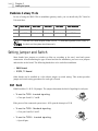
Setting Jumper and Switch
Some boards have jumpers or switches to allow set according to the user’s need and system
construction. After determining the type of board and slot for installation, you have to set jumpers
and switches on the board. The following boards have to be set before installation.
☞ E&M Board
☞ E1/PRI, T1 Board
Other boards can be installed in a slot without jumper or switch setting. This section provides
jumper and switch setting procedures for each type of board.
E&M Board
E&M board has J1~J4/J1~J8 jumpers. The jumpers determine the kind of signaling for each port.
y To use the TYPE I-Inverted signaling,
☞ Close pin O and G, C and B.
A
B O
C
G
NC
If the power of the connected system is not –48V, open the shunt pin of C-B.
y To use the TYPE I-Standard signaling,
☞ Close pin O and B, C and G.
y To use the TYPE II- Inverted signaling,
☞ Open all pins.
A
B O
C
G
NC
3-13
y To use the TYPE II-Standard signaling,
☞ Close pin A and O.
E1/PRI, T1 Board
There are S1 and S2 switches and JP1~JP5 jumpers on the E1/PRI, T1 board. All of these switches
and jumpers are to select the kind of station line to be connected to the E1/PRI, T1 board. Prior to
the installation of the E1/PRI, T1 board onto the MGCB board, set switches and jumpers
according to following directions.
y To connect T1
☞ Close pin #1-2 of all jumpers.
☞ Set S1 switch to ON, and set S2 switch to OFF.
y To connect E1
☞ Close pin #2-3 of all jumpers.
☞ Set both S1 and S2 switches to ON.
y To connect E1 type PRI
☞ Close pin #2-3 of all jumpers.
☞ Set S1 switch to OFF, and set S2 switch to ON.
Installing Daughter Boards
Daughter board is installed according to user’s need and system construction.
The following boards require daughter board installation prior to board installation.
☞ MGCB Board
☞ VOIP Board
Other boards can be installed in a slot without installation of a daughter board.
This section provides daughter board installation procedures for each type of board.
3-14
Chapter 3
Installing the System
MGCB Board
On the MGCB board, the R2 board or E1/PRI, T1 board can be installed.
y To add 8 channel R2 signaling, install a R2 board.
☞ Install the R2 board.
y To connect to E1/PRI, T1 line
☞ Install an E1/PRI, T1 board.
Installing a daughter board on the MGCB board is relatively simple. Fit the daughter board into a
Slot of the MGCB board, and firmly secure it. Slots for a R2 board and E1/PRI, T1 board
installation are as follows.
R2 board
E1/PR1, T1 board
MGCB board
MG
CB
E1/T1
/PR
I
LAN
RS-2
32C
L1
L2
LAN
TX LAN
RX
PWR
OPER
E1
SYNC E1
LOS
3-15
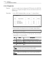
VOIP Board
On the VOIP board, up to 3 VOIP_Sub boards can be installed. Since each VOIP_Sub board
provides 8 VoIP channels, as a result, a maximum of 24 additional VoIP channels can be installed
on the VOIP board.
Although installing VOIP_Sub board on the VOIP board is the same as that of the MGCB board,
you have to be sure of the location of the VOIP_Sub board for installation. From the slot near the
edge connector, install VOIP_Sub boards by one by one.
VOIP_Sub board
VOIP board
LOC1
VOIP
4/8CH
16CH
24CH
LD1
32CH
LD2
LD3
LD4
LD5
LD6
LOC2
LD7
LD8
LOC3
y To install 1 VOIP_Sub board
☞ Install in LOC1 slot.
y To install 2 VOIP_Sub board
☞ Install in LOC1 and LOC2 slots.
y To install 3 VOIP_Sub board
☞ Install in LOC1, LOC2, and LOC3 slots.
3-16
Chapter 3
Installing the System
Installing Board in a Slot
Install a board in the slot of the SMG-3200 system, after procedures for daughter board installation
is completed.
When installing the board, keep the followings in mind.
y The high voltage static-electric charge is easily accumulated in a human body. Deal with the
board after removing all the accumulated electric charge by touching any equipment’s device or
the grounded part.
y Don’t touch the Edge connector of the board and the jumper pin, if possible.
y You have to ground the surface of a workstation, on which the board is place, after wrapping it
with conductor. And you also can put the Ground clip connected to the anti-static carrying bag
to use the station.
y When you have to touch the board, it is recommended to put an anti-static strap on the wrist, if
possible.
After understanding all these cautions, attach the boards on the slots in the following way
according to the system. This section describes board installation procedures in a system slot in the
case of the MGCB board. Other boards can be installed in the same method.
1. Prepare board to install, ensure there is no defect on the board, and ensure the jumper or switch
configuration is correct.
2. Referring the above directions, select a slot for board installation based on the type of board.
3-17
3. Carefully fit the board into the slot following the guardrails on both sides.
Media
Gatew
ay
SMG
-320
0
VOIP
4/8CH
16CH
24CH
32CH
LD1
LD2
LD3
LD4
LD5
LD6
LD7
LOOP
P1
P2
LD8
P3
P4
SLC
MGC
B
E1/T1
P5
P1
P6
P1
P2
P4
P5
L1
PWR
P1
P6
LAN
TX LAN
RX
L2
2C
P5
P7
P8
P3
LAN
RS-23
P3
P7
P2
/PRI
P4
P3
P7
P6
P5
P8
P7
P8
P2
OPER
P4
E1
SYNC E1
LOS
P6
P8
4. Press the center of the front panel of the board so that the board can be completely fit into the
connector on the back-plane board.
5.
After ensuring that the board is connected to the back-plane board, screw down the board.
Media
Gatew
ay
MGC
B
SMG
E1/T1
-320
0
/PRI
LAN
VOIP
RS-23
L1
LAN
TX LAN
RX
L2
2C
PWR
4/8CH
16CH
24CH
32CH
LD1
LD2
OPER
E1
SYNC E1
LOS
LD3
LD4
LD5
LD6
LD7
LOOP
P1
P2
LD8
P3
P4
SLC
P5
P1
P6
P1
P3
P7
P2
P5
P7
P8
P3
P2
P4
P5
P1
P6
P4
P3
P7
P6
P5
P8
P7
P8
P2
P4
P6
P8
3-18
Chapter 3
Installing the System
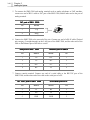
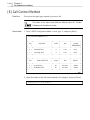
Connecting Cables
After all necessary boards are installed in the SMG-3200 system, connect cables to the ports of the
boards to construct the VoIP network.
In this section, the Pin Numbers of the PBX or KTS port are displayed according
to the Samsung PABX INFOREX. For the case of connecting to other PBX or KTS,
connect cables referring to the Pin Name.
1. To connect the SMG-3200 and PBX or KTS with general trunk, connect one end of a RJ-11
cable to the SLC port of the SMG-3200, and the other end to the LOOP port of the PBX or
KTS.
SLC port of SMG-3200
LOOP port of PBX or KTS
Pin
Name
Name
Pin
3
Tip
Tip 0
1
4
Ring
Ring 0
26
2. To connect the SMG-3200 and PBX or KTS with SLC line, connect one end of a RJ-11 cable
to the LOOP port of the SMG-3200, and the other end to the SLC port of the PBX or KTS.
LOOP port of SMG-3200
SLC port of PBX or KTS
Pin
Name
Name
Pin
3
Tip
Tip 0
1
4
Ring
Ring 0
26
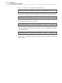
3-19
3. To connect the SMG-3200 and PBX or KTS with E&M line, connect one end of a RJ-11 cable
to the E&M port of the SMG-3200, and the other end to the E&M port of the PBX or KTS. At
this time, connect E line of one and M line of the other, and connect M line of one and E line of
the other.
E&M port of SMG-3200
E&M port of PBX or KTS
Pin
Name
Name
Pin
1
M
E
3
2
TxT
RxT
1
3
RxT
TxT
2
4
RxR
TxR
27
5
TxR
RxR
26
6
E
M
28
4. To connect the SMG-3200 and PBX or KTS with E1/PRI, T1 line, connect one end of a RJ-11
cable to the E1/PRI, T1 port of the SMG-3200, and the other end to the E1/PRI, T1 port of the
PBX or KTS.
E1/PRI, T1 port of SMG-3200
E1/PRI, T1 port of PBX or KTS
Pin
Name
Name
Pin
1
Tx+
Rx+
2
2
Tx-
Rx-
27
4
Rx+
Tx+
1
5
Rx-
Tx-
26
3-20
Chapter 3
Installing the System
5. To connect the SMG-3200 and analog terminal such as analog telephone or FAX machine,
connect one end of RJ-11 cable to SLC port of the SMG-3200, and the other end to the port of
analog terminal.
SLC port of SMG-3200
Pin
Name
3
Tip
4
Ring
6. Connect the SMG-3200 to the network of the site. Connect one end of a RJ-45 cable (Twisted
pair category-5 straight-through) to the LAN port of the SMG-3200, and the other end of the
cable to the Ethernet port of the hub or switch.
LAN port of SMG-3200
Ethernet port of switch
Pin
Name
Name
Pin
1
Tx+
Rx+
1
2
Tx-
Rx-
2
3
Rx+
Tx+
3
6
Rx-
Tx-
6
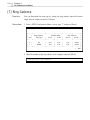
7. Connect console terminal. Connect one end of a serial cable to the RS-232C port of the
SMG-3200, and the other end of the cable to the serial port of a PC.
RS-232C port of SMG-3200
9 Pin Serial port of PC
Pin
Name
Name
Pin
2
Tx
Rx
2
3
Rx
Tx
3
5
GND
GND
5
3-21
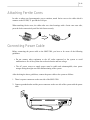
Attaching Ferrite Cores
In order to reduce an electromagnetic waves emission, attach ferrite cores to the cable which it
connects to the E1/PRI, T1 pot and the LAN pot.
When attaching ferrite cores, the cables after two wheel turnings with a ferrite core outer side,
press the locks consecutively until the lock fasten securely.
Connecting Power Cable
Before connecting the power cable to the SMG-3200, you have to be aware of the following
guidelines.
y Do not connect other equipment to the AC outlet connected to the system to avoid
malfunction or fire of the system due to electrical noise and low voltage.
y The AC power source to supply power must be stable and uninterruptible, since power
outages during the night can cause malfunctioning of the system.
After checking the above guidelines, connect the power cable to the system as follows.
1. There is a power connector on the rear side of the SMG-3200.
2. Connect grounded outlet and the power connector on the rear side of the system with the power
cable.
ON(I)
AC 120-240V
OFF(O)
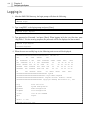
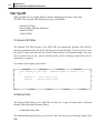
4-1
Chapter 4 Configuring the System
This chapter describes procedures for the configuration of the SMG-3200 operating environment
with console terminal as well as the login procedure in console terminal.
Setting up the Terminal
Terminal setup methods differ according to terminal types and operating system. In this manual,
we will using an example of how to use the hyper terminal on a PC running with a Windows 98
operation system.
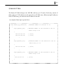
Terminal Features
The user can connect an ASCII terminal such as a VT100 or VT220 or a PC installed with a
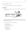
terminal emulation program.
y Emulation
VT100/ANSI Compatible
y Bits per second
38400
y Data bit
8
y Parity
None
y Stop bit
1
y Flow control
Xon/Xoff
Setting up the Terminal
To set up a terminal, follow these steps.
1. Turn on the PC and boot with Windows98.
2. Click [Start] at the bottom and select Programs and select Program Î Accessories Î
Communication Î HyperTerminal.
3. When the <HyperTerminal> window appears, double-click the Hypertrm icon.
4. When the <Connection Description> window appears, type the name of a hyper terminal in the
Name box and select an icon displayed in the Icon box. Then, click [OK].
4-2
Chapter 4
Configuring the System
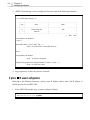
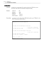
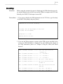
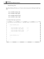
5. Then, the user will have the following <Phone Number> window appears, where the user can
define a location to connect the hyper terminal. Since the terminal is directly connected to the
SMG-3200 through a COM port, click the Connect using box and select a corresponding
COM port.
6. Next, the user will the <COMx Properties> window appears, where the user can configure
various options for the selected COM port. Configure each item as shown in the following and
click [OK].
7. Next, a new hyper terminal where the user can set up the SMG-3200 by using console
commands will pop up.
4-3
Starting SMG-3200
This section describes the login procedure using CLI, after turning on SMG-3200.
Turning on
While the hyper terminal window is on the screen, turn on the SMG-3200 with the power button in
the rear of the system.
ON(I)
OFF(O)
ON(I)
AC 120-240V
OFF(O)
After the system turn on, system initialization proceeds approximately 60 seconds. The system
POST (Power On Self Test) will be executed and the factory-preset configuration data will be
loaded and shown on the terminal.
If booting of the SMG-3200 is successfully completed, then
y On the MGCB board,
☞ L2 LED and PWR LED are on in green.
☞ OPER LED blinks in green.
y On the VOIP board,
☞ 8CH LED is on in green
☞ LD1 LED blinks in green.
4-4
Chapter 4
Configuring the System
Logging in
1. After the SMG-3200 boots up, the login prompt will show the following.
SMG3200 Login:
2. Type ‘smg3200’ at the login prompt and press [Enter].
SMG3200 Login: smg3200
3. Type password at ‘Password:’ and press [Enter]. When logging in for the very first time, enter
‘smg3200v1’. For the security purposes, the password will be not displayed on the terminal.
SMG3200 Login:smg3200
Password:smg3200v1
4. When the user successfully logs in, the following main screen will be displayed.
SSSSSSSSSSSSSSSSSSSSSSSSSSSSSSSSSSSSSSS Welcome to
SSS
SS
SSSS
SSSSSS
SSS
SS SSSSSSSSS S SSS
SSSS SSSSSSSS SSSSS SSSSS SSSS
SSSS
SSS SSSSSSSS SS S S SSS SSSSSSSSS
SS
SS SS SS SS SS
SSSSS SSSSSS SSS SS SS SSSS
SS
SS
SS SS SS SS SS
SSSSSSS SSSS SSSSSSS SSS SSSS SSS
SS
SS
SS SS SS SS
SSSSSSSS SSS SSSSSSS SSSS SSS SSS
SS SS
SS SS SS SS
SS
SSS SSSSSSS SSSSS
SS SSSSS SSSSS
SSSS
SSSS
SSSSSSSSSSSSSSSSSSSSSSSSSSSSSSSSSSSSS System
SSSSSSSSSSSSSSSSSSSSSSSSSSSSSSSSSSS Login Name: smg3200
SSSSSSSSSSSSSSSSSSSSSSSSSSSSSSSSS Program Version: 3200V2.2 :020307
SSSSSSSSSSSSSSSSSSSSSSSSSSSSSSS Copyright Samsung Electronics Co., Ltd.
help
sysmenu
pstnmenu
voipmenu
clicmd
quit
Print This List
System Configuration
PSTN Configuration
VoIP Configuration
List Of CLI Command
Logout
value = 1 = 0x1
SMG3200:165.213.81.230>
4-5
5. Press [Enter] to display the SMG3200 login prompt.
SMG3200:165.213.81.230>
4-6
Chapter 4
Configuring the System
Configuring the Operating Environment
To operate the SMG-3200, only the fundamental information configuration is required, and the
detailed operation environment configuration is configured automatically by using default values.
The following 3 configurations are necessary for the operation of the SMG-3200. Other than these
configurations, additional operation environment configurations are not normally used.
☞ TCP/IP Configuration : IP address, subnet mask, default gateway
☞ System Operation Mode : Gateway operation mode, PCM type
☞ VoIP Configuration : VoIP table/gatekeeper configuration
This section describes how to configure the operating environment after turning on and logging in
the SMG-3200.
Messages displayed in the console terminal emulator in this section may differ
according to the version of system software, and might be different from the
actual messages you can see on the console terminal.
During operation environment configuration, pressing [Enter] without input
value in conversational mode is the same as configuration with the default
value at the current step.
Configuring the TCP/IP
To use the TCP/IP protocol for Internet connection, you must configure network information such
as IP address, subnet mask, and default gateway.
SMG-3200 provides the following two methods for TCP/IP configuration.
❶ Automatic Configuration
Configures TCP/IP information automatically using a DHCP (Dynamic Host Configuration
Protocol) server.
4-7
❷ Manual Configuration
Specify the static IP address, subnet mask and default gateway of the SMG-3200.
Before configuring TCP/IP, determine whether automatically configure TCP/IP information or not.
y Automatic configuration requires DHCP service provided by a DHCP server.
y In case automatic configuration is not available, you have to know the following information
for manual configuration of TCP/IP settings.
- IP address and subnet mask for the SMG-3200
- IP address of default gateway
Option ❶ Automatic Configuration
To set up TCP/IP information automatically using a DHCP server, configure the SMG-3200 as a
DHCP client using the following directions.
1. At the SMG-3200 prompt, type ‘sysmenu’ and press [Enter].
SMG3200:165.213.81.230> sysmenu
2. <System Configuration Menu> screen is displayed. Type ‘0’ and press [Enter].
<<<<< System Configuration Menu >>>>>
[0]
[1]
[2]
[3]
[4]
[5]
[6]
[7]
DHCP Client Setting
Network Configuration
Login ID Configuration
System Upgrade
Display System Version
Default DB Setting
Restart System
Exit
Select ? 0
4-8
Chapter 4
Configuring the System
3. <DHCP Client Setting> screen is displayed. Enter the value as the following indication.
<<<<< DHCP Client Setting >>>>>
+----+---------------------+--------------------------+
| No |
Items
|
Value
|
+----+---------------------+--------------------------+
| 0 |
DHCP Client Set
|
OFF
|
| 1 |
Class ID
|
|
+----+---------------------+--------------------------+
[ - :Null, . :Exit ]
Configuration Item Number:0
*Input ‘0’.
Set DHCP Client? (y: ON, n: OFF): ON -> y
*Input ‘y’ to set the status of the DHCP Client On.
Good
Configuration Item Number: .
*Input ‘.’ to exit the configuration.
#System Configuration has changed. Restart? (y: Now, n: Later) -> y
*Input ‘y’ to reboot the system.
4. Log in again on CLI after the system is restarted.
Option ❷ Manual Configuration
Referring to the following directions, specify static IP address, subnet mask, and IP address of
default gateway for the SMG-3200.
1. At the SMG-3200 prompt, type ‘sysmenu’ and press [Enter].
SMG3200:165.213.81.230> sysmenu
4-9
2. <System Configuration Menu> screen is displayed. Type ‘1’ and press [Enter].
<<<<< System Configuration Menu >>>>>
[0]
[1]
[2]
[3]
[4]
[5]
[6]
[7]
DHCP Client Setting
Network Configuration
Login ID Configuration
System Upgrade
Display System Version
Default DB Setting
Restart System
Exit
Select ? 1
3. <Network Configuration> screen is displayed. Type ‘y’ and press [Enter].
<<<<< Network Configuration >>>>
+---+----------------------+-----------------------------+
| No |
Items
|
Value
|
+---+----------------------+-----------------------------+
| 0 | IP Address
| 165.213.81.230
|
| 1 | Gateway Address
| 165.213.81.1
|
| 2 | Netmask
| 255.255.255.0
|
| 3 | TOS(Type Of Service)
| 0x0
|
| 4 | MAC Address(Read Only)
| SAMSUNG(00-00-F0)-AB-CD-0D
|
+---+----------------------+-----------------------------+
[ . :Exit ]
Change Network Configuration? (y: Yes, n: No) -> y
4. The following message is displayed. Input the IP address of the SMG-3200 and press [Enter].
IP Address (dot form): 165.213.81.230 -> 165.213.81.230
4-10
Chapter 4
Configuring the System
5. Input the IP address of default gateway and press [Enter].
Gateway Address (dot form): 165.213.81.1 -> 165.213.81.1
6. Input the subnet mask for the IP address of the SMG-3200 and press [Enter].
Netmask(dot form): 255.255.255.0 -> 255.255.255.0
7. TOS (Type Of Service) value is used to determine the priority of voice packets transmitted
from the SMG-3200 on the network, which enables the network to provide better QOS
(Quality Of Service). Input appropriate TOS value and press [Enter].
+---------------------------------------------------+
|
TOS(Type Of Service) Field
|
+---------------------------------------------------+
|
7
|
6
|
5
|
4
|
3
|
2
|
1
|
0
|
+---------------------------------------------------+
|
Priority
|
D
|
T
|
R
|
0
|
0
|
+---------------------------------------------------+
D: if 0x10, Minimum Delay
T: if 0x08, Maximum Throughput
R: if 0x04, Maximum Reliability
Range:0x00 ~ 0xFF, Default:0x00
TOS Value (Default: 0x00): 0x00 -> 0
Consult with your network administrator about TOS configuration. To make
TOS configuration effective, network routing equipment connected to the
SMG-3200 have to be configured to support TOS in advance. You can
configure TOS values, if necessary, regardless of DHCP server.
4-11
8. Configured network parameters and message asking you whether to restart system is displayed
as follows. After confirming the parameters type ‘y’ and press [Enter].
Good
>>>
>>>
>>>
>>>
IP Address = 165.213.81.230
Gateway
= 165.213.81.1
Subnet Mask = 255.255.255.0
TOS
= 0
# System Configuration has changed. Restart? (y: Now, n: Later) -> y
9. Log in again on CLI after the system is restarted.
Configuring the System Operation Mode
You have to configure gateway operation mode and PCM type, after TCP/IP configuration.
This section describes procedures for system operation configuration.
Setting up Gateway Operation Mode
SMG-3200 gateway operates in either of the following 2 operation modes.
☞ Tandem Gateway : SMG-3200 communicates with PBX or KTS over PSTN trunk without
subscriber phone connection.
☞ Standalone Gateway : SMG-3200 communicates with analog telephone with PSTN trunk
with subscriber phone connection through SLC port.
Configure gateway operation mode of SMG-3200 referring to the following directions.
4-12
Chapter 4
Configuring the System
1. At the SMG-3200 prompt, type ‘pstnmenu’ and press [Enter].
SMG3200:165.213.81.230> pstnmenu
2. <PSTN Configuration Menu> screen is displayed. Type ‘0’ and press [Enter].
<<<<< PSTN Configuration Menu >>>>>
[0]
[1]
[2]
[3]
[4]
[5]
[6]
[7]
[8]
[9]
[10]
[11]
[12]
[13]
[14]
[15]
[16]
Gateway Operation Mode
PSTN Rerouting Insert Digit
PCM Method
Dial Method
SLC Signal
Trunk Signal
Call Control Method
Ring Cadence
System Tone Cadence
CO Tone Cadence
Gain Control
Diagnosis
MMC Port Block/UnBlock
Display Slot Configuration
Display Port Status
Save & Exit
Exit
Select ? 0
4-13
3. To configure the gateway operation mode of the SMG-3200, type ‘0’ and press [Enter].
<<<<< Gateway Operation Mode >>>>>
+----+-----------------------+----------------+-------------+
| No |
Items
|
Value
|
Default
|
+----+-----------------------+----------------+-------------+
| 0 |
Gateway Operation Mode
|
Tandem Gateway
| Tandem Gateway |
| 1 |
PSTN Inbound LCR Option
|
Disable
|
Disable
|
+----+-----------------------+----------------+-------------+
<<<<< PSTN Inbound LCR Table >>>>>
+----+-----------+-----------++---+-------------+-----------+
| No | Inbound Prefix
|
Max Digit
|| No | Inbound Prefix
|
Max Digit
|
|
|
|
Count
||
|
|
Count
|
+----+-----------+-----------++---+-------------+-----------+
| 2
|
|
0
|| 18 |
|
0
|
| 3
|
|
0
|| 19 |
|
0
|
| 4
|
|
0
|| 20 |
|
0
|
| 5
|
|
0
|| 21 |
|
0
|
| 6
|
|
0
|| 22 |
|
0
|
| 7
|
|
0
|| 23 |
|
0
|
| 8
|
|
0
|| 24 |
|
0
|
| 9
|
|
0
|| 25 |
|
0
|
| 10 |
|
0
|| 26 |
|
0
|
| 11 |
|
0
|| 27 |
|
0
|
| 12 |
|
0
|| 28 |
|
0
|
| 13 |
|
0
|| 29 |
|
0
|
| 14 |
|
0
|| 30 |
|
0
|
| 15 |
|
0
|| 31 |
|
0
|
| 16 |
|
0
|| 32 |
|
0
|
| 17 |
|
0
|| 33 |
|
0
|
+----+-----------+-----------++---+-------------+-----------+
[ . :Exit, - :Null, Enter :Skip ]
Configuration Item Number: 0
4. Type the number of desired gateway operation mode and press [Enter].
Gateway Operation Mode (0:Tandem Gateway, 1:Standalone): Standalone -> 0
5. To close current screen, type ‘.’ and press [Enter].
Configuration Item Number: .
4-14
Chapter 4
Configuring the System
6. Return to the <PSTN Configuration Menu> screen.
Setting up PCM Type
PCM (Pulse Code Modulation) is the most frequently used analog-to-digital encoding (A/D
conversion technique to convert analog voice into digital signal). SMG-3200 provides 2 PCM
types, which are A-law and U-law.
☞ A-law : A-law is an ITU-T (International Telecommunication Union) standard for analog-todigital conversion in PCM. A-law is used in most of the telephone networks in
Europe, and similar to U-law used in North America.
☞ μ-law : μ-law is an ITU-T (International Telecommunications Union)standard for analogto-digital conversion in PCM. μ-law is used in most of the telephone networks in
North America.
SMG-3200 provides A-law type by default. To use μ-law type, trunk board
and station board such as LOOP, SLC, E&M need to be changed.
Setting up the PCM type of the SMG-3200 using the following directions.
4-15
1. In the <PSTN Configuration Menu> screen, type ‘2’ and press [Enter].
<<<<< PSTN Configuration Menu >>>>>
[0]
[1]
[2]
[3]
[4]
[5]
[6]
[7]
[8]
[9]
[10]
[11]
[12]
[13]
[14]
[15]
[16]
Gateway Operation Mode
PSTN Rerouting Insert Digit
PCM Method
Dial Method
SLC Signal
Trunk Signal
Call Control Method
Ring Cadence
System Tone Cadence
CO Tone Cadence
Gain Control
Diagnosis
MMC Port Block/UnBlock
Display Slot Configuration
Display Port Status
Save & Exit
Exit
Select ? 2
2. <PCM Method> screen is displayed. Type ‘0’ and press [Enter].
<<<<< PCM Method >>>>>
+---+-------------------------+----------------+------------+
| No |
Items
|
Value
|
Default
|
+---+-------------------------+----------------+------------+
| 0 |
PCM Type
|
A_LAW
|
A_LAW
|
+---+-------------------------+----------------+------------+
[ . :Exit ]
Configuration Item Number: 0
4-16
Chapter 4
Configuring the System
3. Input the number of desired PCM type and press [Enter].
Configuration Item Number: 0
PCM Type (0:U_LAW, 1:A_LAW): A_LAW -> 1
4. To close current screen, type ‘.’ and press [Enter].
Configuration Item Number: .
5. After returning to the <PSTN Configuration Menu> screen, type ‘16’ and press [Enter].
<<<<< PSTN Configuration Menu >>>>>
[0]
[1]
[2]
[3]
[4]
[5]
[6]
[7]
[8]
[9]
[10]
[11]
[12]
[13]
[14]
[15]
[16]
Gateway Operation Mode
PSTN Rerouting Insert Digit
PCM Method
Dial Method
SLC Signal
Trunk Signal
Call Control Method
Ring Cadence
System Tone Cadence
CO Tone Cadence
Gain Control
Diagnosis
MMC Port Block/UnBlock
Display Slot Configuration
Display Port Status
Save & Exit
Exit
Select ? 16
6. Message asking if you want to save the changed configuration in flash memory is displayed.
Type ‘y’ and press [Enter].
# PSTN Configuration has changed. Save? (y: Yes, n: No) -> y
7. Changed data is saved in flash memory, and you are returned to the initial screen of the
SMG-3200 CLI interface.
4-17
Configuring the VoIP
This section describes the procedures for the SMG-3200 VoIP configuration. The SMG-3200 VoIP
configuration procedure is determined by the Gatekeeper service that translates terminal aliases
such as telephone number in E.164 format, e-mail address, and H.323 ID into an IP address.
❶ When not using Gatekeeper
You have to create the VoIP table. To create the VoIP table, consult with the network
administrator for required information.
❷ When using Gatekeeper
Register the information of Gatekeeper. The following information is required for registration.
y IP address and Alias (host name) of Gatekeeper
y H.323 ID and E.164 ID of the SMG-3200 to be registered in Gatekeeper
Option ❶ When not using Gatekeeper
Create the VoIP table according to the following directions.
1. At the SMG-3200 prompt, type ‘voipmenu’ and press [Enter].
SMG3200:165.213.81.230> voipmenu
2. <VoIP Configuration Menu> screen is displayed. Type ‘5’ and press [Enter].
<<<<< VoIP Configuration Menu >>>>>
[0]
[1]
[2]
[3]
[4]
[5]
[6]
[7]
[8]
VoIP
VoIP
VoIP
VoIP
VoIP
VoIP
VoIP
Save
Exit
General Option
DSP Option
Gatekeeper Option
Routing Table
Caller ID Table
Remote IP Table
Remote IP Status
& Exit
Select ? 5
4-18
Chapter 4
Configuring the System
3. Message as follows is displayed. Type ‘0’ and press [Enter].
IP Table Index Number(Range: 0 ~ 31): 0
4. <VoIP Remote IP Table> screen is displayed. Type the number of the VoIP table to configure
and press [Enter].
<<<<< VoIP Remote IP Table >>>>>
+-----+--------------------+-----+--------------------+
| No |
IP Address
| No |
IP Address
|
+-----+--------------------+-----+--------------------+
|
0
|
168.213.81. 230
| 16
|
0. 0. 0. 0
|
|
1
|
0. 0. 0. 0
| 17
|
0. 0. 0. 0
|
|
2
|
0. 0. 0. 0
| 18
|
0. 0. 0. 0
|
|
3
|
0. 0. 0. 0
| 19
|
0. 0. 0. 0
|
|
4
|
0. 0. 0. 0
| 20
|
0. 0. 0. 0
|
|
5
|
0. 0. 0. 0
| 21
|
0. 0. 0. 0
|
|
6
|
0. 0. 0. 0
| 22
|
0. 0. 0. 0
|
|
7
|
0. 0. 0. 0
| 23
|
0. 0. 0. 0
|
|
8
|
0. 0. 0. 0
| 24
|
0. 0. 0. 0
|
|
9
|
0. 0. 0. 0
| 25
|
0. 0. 0. 0
|
|
10 |
0. 0. 0. 0
| 26
|
0. 0. 0. 0
|
|
11 |
0. 0. 0. 0
| 27
|
0. 0. 0. 0
|
|
12 |
0. 0. 0. 0
| 28
|
0. 0. 0. 0
|
|
13 |
0. 0. 0. 0
| 29
|
0. 0. 0. 0
|
|
14 |
0. 0. 0. 0
| 30
|
0. 0. 0. 0
|
|
15 |
0. 0. 0. 0
| 31
|
0. 0. 0. 0
|
+-----+--------------------+-----+--------------------+
[ . :Exit ]
Configuration Item Number: 1
5. Input IP address of opposite VoIP equipment to be connected to the SMG-3200 and press
[Enter].
IP Address (dot form): 0.0.0.0 ->
6. To register the IP address of other VoIP equipment, repeat steps 4 ~ 5.
4-19
7. After VoIP table creation is completed, type ‘.’ and press [Enter].
Configuration Item Number: .
8. To close current screen, type ‘.’ and press [Enter].
IP Table Index Number(Range: 0 ~ 31): .
9. After returning to the <VoIP Configuration Menu> screen. Type ‘8’ and press [Enter].
<<<<< VoIP Configuration Menu >>>>>
[0]
[1]
[2]
[3]
[4]
[5]
[6]
[7]
[8]
VoIP
VoIP
VoIP
VoIP
VoIP
VoIP
VoIP
Save
Exit
General Option
DSP Option
Gatekeeper Option
Routing Table
Caller ID Table
Remote IP Table
Remote IP Status
& Exit
Select ? 8
10. Message asking if you want to save the changed configuration in flash memory is displayed.
Type ‘y’ and press [Enter].
# VoIP Configuration has changed. Save? (y: Yes, n: No) -> y
11. Changed data is saved in flash memory.
4-20
Chapter 4
Configuring the System
Option ❷ When using Gatekeeper
Configure Gatekeeper information according to the following directions.
1. At the SMG-3200 prompt, type ‘voipmenu’ and press [Enter].
SMG3200:165.213.81.230> voipmenu
2. <VoIP Configuration Menu> screen is displayed. Type ‘2’ and press [Enter].
<<<<< VoIP Configuration Menu >>>>>
[0]
[1]
[2]
[3]
[4]
[5]
[6]
[7]
[8]
VoIP
VoIP
VoIP
VoIP
VoIP
VoIP
VoIP
Save
Exit
General Option
DSP Option
Gatekeeper Option
Routing Table
Caller ID Table
Remote IP Table
Remote IP Status
& Exit
Select ? 2
4-21
3. <VoIP Gatekeeper Option> screen is displayed. Type ‘0’ and press [Enter].
<<<<< VoIP Gatekeeper Option >>>>>
+--+--------------------+-------------------+---------------+
| No |
Items
|
Value
|
Default
|
+--+--------------------+-------------------+---------------+
| 0 | Gatekeeper Connection
| Disable
|
Disable
|
|
| Gatekeeper Status
| Unregistration
|
..
|
| 1 | RAS Method
| Auto
|
Auto
|
| 2 | Registration Type
| E.164 in GW Name
|
GW Name
|
| 3 | Gatekeeper Type
| Other GK
|
Other GK
|
| 4 | GW Routing In GK mode
| Disable
|
Disable
|
| 5 | Gatekeeper IP
| 0.0.0.0
|
..
|
| 6 | Gatekeeper Alias
| Gatekeeper
|
..
|
| 7 | Alternative Gatekeeper IP
| 0.0.0.0
|
..
|
| 8 | Gatekeeper Down Option
| Alternative GK
|
Alternative
|
| 9 | Gateway Name| H.323 ID
| SMG3200
|
..
|
| 10 | E.164
|
3200
|
..
|
+--+--------------------+-------------------+---------------+
[ . :Exit, - :Null ]
Configuration Item Number:
4. Message is displayed as follows. Type ‘1’ and press [Enter].
Gatekeeper Connection (0:Disable, 1:Enable): Disable -> 1
5. To specify IP address of Gatekeeper, type ‘5’ and press [Enter].
Configuration Item Number: 5
6. Input IP address of Gatekeeper and press [Enter].
Gatekeeper IP Address (dot form): 165.213.81.230 -> 165.213.81.58
7. To specify alias name (host name) of Gatekeeper, type ‘6’ and press [Enter].
Configuration Item Number: 6
4-22
Chapter 4
Configuring the System
8. Input alias name (host name) of gatekeeper and press [Enter].
Gatekeeper Alias Name : Gatekeeper -> Gatekeeper1
9. To specify H.323 ID of the SMG-3200, type ‘9’ and press [Enter].
Configuration Item Number: 9
10. Input H.323 ID of the SMG-3200 for login and press [Enter].
Gateway Name H.323 ID : pa-37 -> pa-27
11. To close the current screen, type ‘.’ and press [Enter].
Configuration Item Number: .
12. After returning to the <VoIP Configuration Menu> screen, type ‘8’, and press [Enter].
<<<<< VoIP Configuration Menu >>>>>
[0]
[1]
[2]
[3]
[4]
[5]
[6]
[7]
[8]
VoIP
VoIP
VoIP
VoIP
VoIP
VoIP
VoIP
Save
Exit
General Option
DSP Option
Gatekeeper Option
Routing Table
Caller ID Table
Remote IP Table
Remote IP Status
& Exit
Select ? 8
13. Message asking if you want to save the changed configuration in flash memory is displayed.
Type ‘y’ and press [Enter].
# VoIP Configuration has changed. Save? (y: Yes, n: No) -> y
14. Changed data is saved in flash memory.
5-1
Chapter 5 CLI (Command Line Interface)
This chapter presents the CLI that allows operational configuration of the SMG-3200. An
overview of menus followed by a description of functions for each menu and settings for
submenus is given.
Menu Configuration
The CLI menu of the SMG-3200 consists of 6 main menus. Each menu has a number of submenus,
except for ‘help’ and ‘quit’ menus.
Main Menu
Sub Menu
help
No
sysmenu
[0] DHCP Client Setting
[1]Network Configuration
[2]Login ID Configuration
[3] System Upgrade
[4] Display Package Information
[5] Default DB Setting
[6] Restart System
[7] Exit
[0] Gateway Operation Mode
[1] PSTN Rerouting Insert Digit
[2] PCM Method
[3] Dial Method
[4] SLC Signal
[5] Trunk Signal
[6] Call Control Method
[7] Ring Cadence
[8] System Tone Cadence
[9] CO Tone Cadence
[10] Gain Control
[11] Diagnosis
[12] MMC Port Block/UnBlock
[13] Display Slot Configuration
[14] Display Port Status
[15] Save & Exit
[16] Exit
[0]VoIP General Option
[1]VoIP DSP Option
[2]VoIP Gatekeeper Option
pstnmenu
VoIPmenu
5-2
Chapter 5
CLI (Command Line Interface)
[3]VoIP Routing Table
[4]VoIP Caller ID Table
[5]VoIP Remote IP Table
[6]VoIP Remote IP Status
[7] Save & Exit
[8] Exit
clicmd
clicmd
cdrhelp
date
dbfilehelp
quit
optionhelp
settime
No
5-3
Using Menus
Make sure that you familiarize yourself with the following instructions on the CLI Menus of the
SMG-3200.
y Selecting the Main Menu
To select the Main Menu from prompt on the SMG-3200 main screen, type in the name of the
desired menu. For example, type ‘sysmenu’ and press [Enter] to select sysmenu.
y Selecting a Submenu
To select a submenu, type the number of the desired submenu. For example, type ‘0’ and press
[Enter] to select 0) DHCP Client Setting on the System Configuration Menu.
When you using the ‘clicmd’ menu, just input the string of submenu name at the
SMG3200:xxxx.xxx.xx.xxx> prompt in the main screen. Each submenu itself can be CLI command,
or has another submenu.
y Back to the Previous Screen
To close the current menu screen and return to the previous screen, type in the number
corresponding to Exit in the menu.
In addition to the above, you can follow the guide that appears on the bottom of the screen every
time you select a menu.
Each menu item will be explained in detail in the following sections.
5-4
Chapter 5
CLI (Command Line Interface)
System Configuration Menu
You can set overall system functions, such as IP address and login password, of the SMG-3200
from the System Configuration Menu. You can also view values of parameters such as system
version information.
The following <System Configuration Menu> screen will appear when you type ‘sysmenu’ and
press [Enter] from the prompt on the main screen.
<<<<< System Configuration Menu >>>>>
[0] DHCP Client Setting
[1] Network Configuration
[2] Login ID Configuration
[3] System Upgrade
[4] Display Package Information
[5] Default DB Setting
[6] Restart System
[7] Exit
Select ?
The following table shows an overview of the 8 submenus found in the System Configuration
Menu.
No
Menu
Functions
0
DHCP Client Setting
Sets the SMG-3200 as a DHCP client.
1
Network Configuration
Configures static IP address, subnet mask and
gateway.
2
Login ID Configuration
Configures login name and password.
3
System Upgrade
Upgrades the system software.
4
Display Package Information
Displays the version of system program.
5
Default DB Setting
Resets item values by type of database with default
values.
6
Restart System
Restarts the system.
7
Exit
Closes the System Configuration Menu screen.
5-5
[0] DHCP Client Setting
Function
You can set the SMG-3200 as a DHCP client. By doing so, the DHCP server
automatically allocates an IP address for the SMG-3200. After the setup, you must
restart the system to implement the change.
Default
Value
DHCP Client Set
Class ID
Procedure
1. In the <System Configuration Menu> screen, type ‘0’, and press [Enter].
OFF
(none)
<<<<< DHCP Client Setting >>>>>
+----+---------------------+----------------+
| No |
Items
|
Value
|
+--------------------------+----------------+
| 0
|
DHCP Client Set
|
OFF
|
| 1
|
Class ID
|
|
+----+---------------------+----------------+
[- :Null, . :Exit ]
2. To set the SMG-3200 as a DHCP client, select 0 in Configuration Item
Number, press [Enter], and type ‘y’.
Set DHCP Client? (y: ON, n: OFF): ON ->
3. When Class ID is needed, select 1 in Configuration Item Number, press [Enter],
and type ‘y’. Enter Class ID if it is necessary in DHCP server.
4. A message asking whether to restart the system will be displayed. To restart
immediately, type ‘y’ or type ‘n’ otherwise and press [Enter].
# System Configuration has changed. Restart? (y: Now, n: Later) ->
5-6
Chapter 5
CLI (Command Line Interface)
[1] Network Configuration
Function
Users can set the network configuration such as IP address for the SMG-3200,
default gateway address and subnet mask. After setup, you must restart the system
to implement the change.
Procedure
1. In the <System Configuration Menu> screen, type ‘1’, and press [Enter].
<<<<< Network Configuration >>>>
+---+-------------------+-----------------------+
| No |
Items
|
Value
|
+-----------------------+-----------------------+
| 0 |
IP Address
|
165.213.81.230
|
| 1 |
Gateway Address
|
165.213.81.1
|
| 2 |
Netmask
|
255.255.255.0
|
| 3 |
TOS(Type Of Service)
|
0x0
|
| 4 |
MAC Address(Read Only)
| SAMSUNG(00-00-F0)-AB-CD-0D |
+---+-------------------+-----------------------+
[ . :Exit ]
2. To change the network information, type ‘y’, and press [Enter].
Change Network Configuration? (y: Yes, n: No) ->
3. Input a new IP address for the SMG-3200 and press [Enter].
IP Address (dot form): 165.213.81.230 ->
4. Input an IP address for the default gateway and press [Enter].
Gateway Address (dot form): 165.213.81.1 ->
5. Input a subnet mask and press [Enter].
Netmask(dot form): 255.255.255.0 ->
5-7
6. Set a TOS value in consultation with your network administrator at the site.
TOS (Type Of Service) requests a router for a specific service to effectively
process voice packets (that are transmitted from the SMG-3200) on the
network. Refer to the definition of terms listed in the Appendix D for a full
description of TOS.
+-------------------------------+
|
TOS(Type Of Service) Field
|
+-------------------------------+
| 7 | 6
|5 | 4 | 3 | 2 | 1 | 0 |
+-------------------------------+
|
Priority
| D | T | R | 0 | 0 |
+-------------------------------+
D: if 0x10, Minimum Delay
T: if 0x08, Maximum Throughput
R: if 0x04, Maximum Reliability
Range:0x00 ~ 0xFF, Default:0x00
TOS Value (Default: 0x00): 0x00 ->
When you set TOS for the SMG-3200, you must set router to
support the TOS. You can configure TOS values, if necessary,
to process QoS (Quality of Service) regardless of whether
using a DHCP server or not.
7. A message asking whether to restart the system will be displayed as follows.
To restart immediately, type ‘y’ or type ‘n’ otherwise and press [Enter].
# System Configuration has changed. Restart? (y: Now, n: Later) ->
MAC Address
MAC Address is a fixed address that is allocated to a network
controller of the SMG-3200. It cannot be modified by users.
5-8
Chapter 5
CLI (Command Line Interface)
[2] Login ID Configuration
Function
You can change the login name and password of CLI.
Default
Value
Login Name
smg3200
Login Passwd smg3200v1
Procedure
1. In the <System Configuration Menu> screen, type ‘2’, and press [Enter].
<<<<< Login ID Configuration >>>>>
+----+---------------------+------------------+
| No |
Items
|
Value
|
+----+---------------------+------------------+
|
0 |
Login Name
|
smg3200
|
|
1 |
Login Passwd
|
smg3200v1
|
+----+---------------------+------------------+
[ . :Exit ]
2. To change the login name and password of CLI, type ‘y’, and press [Enter].
Change Login Name and Passwd? (y: Yes, n: No) ->
3. Input a new login name and press [Enter]. The new login name must be
different from the default or previous login names.
Enter New Login Name: smg3200 ->
4. Input a new password.
Enter New Passwd: smg3200v1 ->
5. A message asking whether to restart the system will be displayed as follows.
To restart immediately, type ‘y’ or type ‘n’ otherwise and press [Enter].
# System Configuration has changed. Restart? (y: Now, n: Later) ->
5-9
[3] System Upgrade
Function
You can view the system upgrade information, or change the program of the DSP
chip for VoIP and the operation program for the SMG-3200 using TFTP or FTP.
Changes are stored in the system’s flash memory and will be implemented when
the system is rebooted.
There are two ways to upgrade the system of the SMG-3200:
❶ TFTP : It receives the system program stored on a TFTP server at a remote
location through TFTP protocol and changes the program. The system
program to be changed must be stored under the “/tftpboot” directory
in the TFTP server.
❷ FTP
Procedure
: When there is no TFTP server, it first receives the program to be
changed through FTP protocol. By selecting the FTP method and
typing in the number of files in the system program, the system
program will be changed.
1. In the <System Configuration Menu> screen, type ‘3’, and press [Enter].
<<<<< System Upgrade >>>>
[TFTP Method]
+---+----------------------------+---------------+
| NO |
Items
|
Value
|
+---+----------------------------+---------------+
| 0 | TFTP Server Address
|
165.213.81.10
|
| 1 | Upgrade Status
|
SUCCESS
|
| 2 | Working Program Version
|
3200V2.2:020307
|
| 3 | Saved Program Version
|
3200V2.2:020307
|
| 4 | Total Program File Count
|
30
|
| 5 | Saved Program File Count
|
30
|
| 6 | DSP Package File Count
|
2
|
| 7 | Main Package File Count
|
28
|
+---+----------------------------+---------------+
[FTP Method]
+---+----------------------------+---------------+
| No |
Items
|
Value
|
+---+----------------------------+---------------+
| 0 |
DSP Package File Count
|
2
|
|
|
Main Package File Count
|
28
|
+---+----------------------------+---------------+
[ . :Exit ]
5-10
Chapter 5
CLI (Command Line Interface)
2. To upgrade the system software, type ‘y’, and press [Enter].
Upgrade This System? (y: Yes, n: No) -> y
3. Select an upgrade method and press [Enter].
Upgrade Method (1: TFTP, 2: FTP) ->
4. When TFTP is selected, input the IP address of the TFTP server. When FTP is
selected.
TFTP Server Address (dot form): 165.213.81.10 ->
5. Input the number of files in the DSP Chip program for VoIP. When none of the
DSP Chip programs for VoIP are to be upgraded, type ‘0’ and press [Enter].
DSP Package File Count: 2 ->
6. Input the number of system operation program files. When none of the system
operation programs are to be upgraded, type ‘0’ and press [Enter].
Main Package File Count: 28 ->
7. A message asking you whether to restart the system will be displayed as
follows. To restart immediately, type ‘y’ or type ‘n’ otherwise and press
[Enter].
# System Configuration has changed. Restart? (y: Now, n: Later) ->
The number of DSP files or system operation files can be
changed according to the version of system program.
5-11
[4] Display Package Information
Function
You can view the version information of the program that is installed in the
system.
Procedure
1. In the <System Configuration Menu> screen, type ‘4’, and press [Enter].
<<<<< Display Package Information >>>>
+---+----------------------------+----------------+
| No |
Items
|
Value
|
+---+----------------------------+----------------+
| 0 | Boot ROM Version
|
BootROM ver 1.1
|
| 1 | Working Program Version
|
3200V2.2:020307
|
| 2 | Saved Program Versio
|
3200V2.2:020307
|
| 3 | Total Program File Count
|
30
|
| 4 | Saved Program File Count
|
30
|
| 5 | Upgrade Status
|
SUCCESS
|
| 6 | EMS
|
Disabled
|
+---+----------------------------+----------------+
[ . :Exit ]
2. The following information will appear.
y Boot ROM Version : Version of the Boot ROM.
y Working Program Version : Version of the program currently in operation.
y Saved Program Version : Version of the program stored in flash memory.
y Total Program File Count : Number of program files.
y Saved Program File Count : Number of program files stored in flash
memory.
y Upgrade Status : Status of the latest upgraded system program.
y EMS: Indicates whether EMS (Element Management System), the GUI
maintenance tool for the SMG-3200, is enabled.
5-12
Chapter 5
CLI (Command Line Interface)
[5] Default DB Setting
Function
You can set all values of each variable in the SMG-3200 to default values, by
database type.
Procedure
1. In the <System Configuration Menu> screen, type ‘5’, and press [Enter].
2. When the following message appears, select which database variables are to be
changed to default values and press [Enter]. To change all database variable
values with default values, select ‘0’.
Set Default DB (0: All, 1: System, 2: PSTN, 3: VoIP )
3. It will automatically find and set the old values to the default values. The
screen below the case you selected ALL.
>>> Set Default System DB(Default Login ID):
Good
>>> Set Default System DB(Default Password):
Good
>>> Set Default System DB(DHCP Client Off ):
Good
>>> Set Default PSTN DB(PSTN Configuration):
Good
>>> Set Default VoIP DB(VoIP Configuration):
Good
4. Upon completion, a message asking whether to restart the system will be
displayed as follows. To restart immediately, type ‘y’ or type ‘n’ otherwise and
press [Enter].
# System Configuration has changed. Restart? (y: Now, n: Later) ->
5-13
[6] Restart System
Function
When you execute the system restart command the system will restart provided
that the value of Upgrade Status on the 4) Display Package Information menu
is ‘SUCCESS’. If the value is ‘Fail’ or ‘Loading’, the system will not restart and a
warning message will appear. This is because the system will not operate properly
when the restart command is given when the system update has not been properly
completed.
Procedure
1. In the <System Configuration Menu> screen, type ‘6’, and press [Enter].
Restart System? (y: Yes, n: No)
2. To restart the system, type ‘y’, and press [Enter].
[7] Exit
Function
This closes the <System Configuration Menu> screen and returns to the main
menu screen.
Procedure
In the <System Configuration Menu> screen, type ‘7’ and press [Enter].
5-14
Chapter 5
CLI (Command Line Interface)
PSTN Configuration Menu
In the PSTN Configuration Menu, you can set the PSTN interface that is required to connect to
the PSTN trunk line. You can also view the values of parameters.
At the SMG-3200 prompt of the main screen, type ‘pstnmenu’ and press [Enter]. The following
PSTN Configuration Menu screen will be displayed.
<<<<< PSTN Configuration Menu >>>>>
[0] Gateway Operation Mode
[1] PSTN Rerouting Insert Digit
[2] PCM Method
[3] Dial Method
[4] SLC Signal
[5] Trunk Signal
[6] Call Control Method
[7] Ring Cadence
[8] System Tone Cadence
[9] CO Tone Cadence
[10] Gain Control
[11] Diagnosis
[12] MMC Port Block/UnBlock
[13] Display Slot Configuration
[14] Display Port Status
[15] Save & Exit
[16] Exit
Select ?
5-15
The following is an overview of the 17 submenus found in the PSTN Configuration Menu.
No
Menu
Functions
0
Gateway Operation Mode
Sets the system operation mode.
1
PSTN Rerouting Insert Digit
When PSTN routing, it configures a trunk line access
code used in either PBX or KTS.
2
PCM Method
Sets PCM mode.
3
Dial Method
Sets the trunk line digit transmission method.
4
SLC Signal
Sets the signal type of analog interface.
5
Trunk Signal
Sets the signal type of digital interface.
6
Call Control Method
Sets the signal type for call control.
7
Ring Cadence
Sets the system ring cadence.
8
System Tone Cadence
Sets the system tone cadence.
9
CO Tone Cadence
Sets the CO tone cadence.
10
Gain Control
Adjusts call quality depending on the connection type.
11
Diagnosis
Sets the diagnosis interval for PSTN interface.
12
MMC Port Block/UnBlock
Specifies use of a specific port.
13
Display Slot Configuration
Views configuration of cards installed in system slots.
14
Display Port Status
15
Save & Exit
16
Exit
Views system slots and operation status of ports.
Closes the PSTN Configuration Menu screen with saving
changes.
Closes the PSTN Configuration Menu screen without
saving changes.
5-16
Chapter 5
CLI (Command Line Interface)
[0] Gateway Operation Mode
Function
(1) Gateway Operation Mode
The SMG-3200 operates in either of the following modes. In this menu you can
configure the operation mode of the SMG-3200.
- Tandem Gateway : You can connect the SMG-3200 to PBX or KTS, and use the
system as a gateway without internal subscribers.
- Standalone Gateway : You can connect a telephone to a SLC port on the SMG3200, and use the system as a gateway with internal subscribers.
(2) PSTN Inbound LCR Option
SMG-3200 analyzes the dialing digits coming from PABX, KTS, and telephones
and decides whether or not the dialing is terminated.
Procedure
1. In the <PSTN Configuration Menu> screen, type ‘0’, and press [Enter].
<<<<< Gateway Operation Mode >>>>>
+---+--------------------+--------------+-----------+
| No |
Items
|
Value
|
Default
|
+---+--------------------+--------------+-----------+
| 0 |
Gateway Operation Mode
|
Tandem Gateway | Tandem Gateway |
| 1 |
PSTN Inbound LCR Option
|
Disable
|
Disable
|
+---+--------------------+--------------+-----------+
<<<<< PSTN Inbound LCR Table >>>>>
+---+----------------+---------++----+---------------+--------+
| No| Inbound Prefix |Max Digit|| No | Inbound Prefix |MaxDigit|
|
|
| Count ||
|
| Count |
+---+----------------+---------++----+---------------+--------+
| 2 |
|
0
|| 18 |
|
0
|
| 3 |
|
0
|| 19 |
|
0
|
| 4 |
|
0
|| 20 |
|
0
|
| 5 |
|
0
|| 21 |
|
0
|
| 6 |
|
0
|| 22 |
|
0
|
| 7 |
|
0
|| 23 |
|
0
|
| 8 |
|
0
|| 24 |
|
0
|
| 9 |
|
0
|| 25 |
|
0
|
|10 |
|
0
|| 26
|
|
0
|
5-17
(Continued)
| 11 |
|
0
|| 27 |
|
0
|
| 12 |
|
0
|| 28 |
|
0
|
| 13 |
|
0
|| 29 |
|
0
|
| 14 |
|
0
|| 30 |
|
0
|
| 15 |
|
0
|| 31 |
|
0
|
| 16 |
|
0
|| 32 |
|
0
|
| 17 |
|
0
|| 33 |
|
0
|
+--+-----------+-------++---+----------+-------+
[ . :Exit, - :Null, Enter :Skip ]
Configuration Item Number:0
2. To change the operation mode of the SMG-3200, type ‘0’ in the above screen,
and press [Enter].
Configuration Item Number: 0
3. To change the operation mode to Tandem Gateway or Standalone, press ‘0’ or
‘1’ respectively, and press [Enter].
Gateway Operation Mode (0:Tandem Gateway, 1:Standalone):
Tandem Gateway ->
4. To set the PSTN Inbound LCR Option, type ‘1’ in the above <<<<< Gateway
Operation Mode >>>>> screen and press [Enter]. It enables PSTN Inbound LCR
Option.
Configuration Item Number: 1
5-18
Chapter 5
CLI (Command Line Interface)
5. Then, select 2 to 33 as a Configuration Item Number and enter Inbound Prefix
and Maxdigit count. This value analyzes dialing digits to decide the
termination of dialing.
- Inbound Prefix: the prefix pattern of dialing digits coming into SMG-3200
- Max Digit Count: The maximum number of dialing digits coming into
SMG-3200 with the designated prefix.
Configuration Item Number: 2
Inbound Prefix: ->
Max Digit Count : 0 ->
Inbound LCR PSTN Option decides whether or not the dialing
is terminated coming into SMG-3200. Generally dialing is
considered to be terminated when ‘#’ came in or dialing
timeout occurred. Without ‘#’ or dialing timeout, however,
when the designated number of dialing digits for the
assigned prefix are incoming, it is considered the dialing
termination.
This feature shortens the call connetion time for SMG-3200
because SMG-3200 decides the dialing termination without
any other termination separators.
5-19
[1] PSTN Rerouting Insert Digit
Function
The SMG-3200 system provides a function called PSTN rerouting (or PSTN
Detour). PSTN rerouting is used to reroute a call set by a VOIP to PSTN network
bypassing an IP network in the case of having poor QoS (Quality Of Service), or
detecting IP network being busy or disconnected or in error.
At the time of PSTN rerouting, an access code is required for PABX or KTS
connected to SMG-3200 to access the PSTN trunk line depending on the
environment of the operating site. This access code can be specified.
Procedure
1. In the <PSTN Configuration Menu> screen, type ‘1’, and press [Enter].
<<<<< PSTN Rerouting Insert Digit >>>>>
+---+----------------------+----------+-----------+
| No |
Items
|
Value
|
Default
|
+---+----------------------+----------+-----------+
| 0 |
Rerouting Insert Digit
|
None
|
None
|
+---+----------------------+----------+-----------+
[ . :Exit ]
2. To change the access code for PSTN Rerouting, type ‘0’, and press [Enter].
Configuration Item Number: 0
3. Input a trunk access code, and press [Enter].
PSTN Rerouting Insert Digit: (N: None)
None
->
5-20
Chapter 5
CLI (Command Line Interface)
[2] PCM Method
Function
PCM (Pulse Code Modulation) is the most frequently used analog-to-digital
encoding (A/D conversion technique to convert analog voice into digital signal).
SMG-3200 provides 2 PCM types, which are A-law and μ-law. In this menu,
PCM type can be changed.
The PCM coding method of the PBX or KTS connected to the
SMG-3200 system must be set the same.
Procedure
1. In the <PSTN Configuration Menu> screen, type ‘2’, and press [Enter].
<<<<< PCM Method >>>>>
+---+-------------------+---------------+---------+
| No |
Items
|
Value
|
Default
|
+---+-------------------+---------------+---------+
| 0 |
PCM Type
|
A_LAW
|
A_LAW
|
+---+-------------------+---------------+---------+
[ . :Exit ]
2. To change the PCM coding method, type ‘0’, and press [Enter].
Configuration Item Number:
3. To change the PCM coding method to U_LAW or A_LAW, type ‘0’ or ‘1’
respectively, and press [Enter].
PCM Type (0:U_LAW, 1:A_LAW): A_LAW ->
5-21
[3] Dial Method
Function
You can set the digit transmission method and its options on the trunk connected
to a PSTN interface.
MFC (DTMF) : The digit transmission method that is used to send pressed
numbers on a tone telephone. When MFC is used, the holding
time for MFC digits must be specified on 1. DTMF Holding
Time item.
Dial Pulse : The digit transmission method that is used to send dialed numbers on
a pulse telephone.
R2MFC : The digit transmission method that is used in digital trunks such as E1
or T1. Depending on the site environment, options such as Calling
Number ID or Called Number ID must be specified.
Procedure
1. In the <PSTN Configuration Menu> screen, type ‘3’, and press [Enter].
<<<<< Dial Method >>>>>
+---+----------------------+------------+---------+
| No |
Items
|
Value
|
Default
|
+---+----------------------+------------+---------+
| 0 | Dial Type Selection
|
MFC
|
MFC
|
| 1 | DTMF Holding Time
|
1
|
1
|
+---+----------------------+------------+---------+
[Unit: 100msec]
+---+----------------------+------------+---------+
| No |
R2 Signal Items
|
Value
|
Default
|
+---+----------------------+------------+---------+
| 2 | Calling Number Request
|
OFF
|
OFF
|
| 3 | Calling Number Response
|
OFF
|
OFF
|
| 4 | Called Status Request
|
OFF
|
OFF
|
| 5 | Called Status Response
|
OFF
|
OFF
|
| 6 | Calling Extension Response
|
OFF
|
OFF
|
+---+----------------------+------------+---------+
[ . :Exit ]
5-22
Chapter 5
CLI (Command Line Interface)
2. Input the number of the dial method to be changed, and press [Enter].
Configuration Item Number:
3. Specify a value referring to the following table, and press [Enter].
No
Item
Description
Selects a trunk digit transmission type.
0
Dial Type Selection
0. MFC : Multi-Frequency (DTMF) type
1. PULSE : Pulse type
2. R2MFC : R2MFC type
1
DTMF Holding Time
(1 ~ 99)
Specifies MFC digit holding time. Typed
number x 100msec is the holding time.
2
Calling Number Request
3
Calling Number Response
4
Called Status Request
Sets whether you request (ON) or not (OFF)
the other party for call status.
5
Called Status Response
Sets whether you accept (ON) or not (OFF)
the caller’s request for call status.
6
Calling Extension
Response
Must be specified when the SMG-3200 is
used in Standalone mode, but it is currently
not in service.
Sets whether caller’s number identification is
to be requested (ON) or not (OFF) to the
other party.
Sets whether you accept (ON) or not (OFF)
the other party’s request for caller’s number
identification.
Number 0 and 1 are used in MFC type and the rest are used in
R2MFC type.
5-23
[4] SLC Signal
Function
You can set the signal type of the SLC interface.
Procedure
1. In the <PSTN Configuration Menu> screen, type ‘4’, and press [Enter].
<<<<< SLI Signal >>>>>
+---+-------------------+------+---------+-------+
| No | SLI Signal Timer
| Value
|
Unit
| Default |
+---+-------------------+------+---------+-------+
| 0 |
Hook Off Time
|
1
| 100 msec |
1
|
| 1 |
Hook On Time
|
50
| 10 msec
|
50
|
| 2 |
Hook Flash MIN. Time
|
10
| 10 msec
|
10
|
| 3 |
Hook Flash MAX. Time
|
30
| 10 msec
|
30
|
+---+-------------------+------+---------+-------+
[ . :Exit ]
2. Input the number of the SLC signal to be changed, and press [Enter].
Configuration Item Number:
3. Specify a value referring to the following table, and press [Enter].
No
Item
0
Hook Off Time
1
2
3
Description
The minimum time elapsed to recognize hook off of
an analog telephone. Typed number x 100msec is
the actual hook off time.
The minimum time elapsed to recognize hook on of
Hook On Time
an analog telephone. Typed number x 10msec is the
actual hook on time.
The minimum time elapsed to recognize hook flash
Hook Flash MIN.
of an analog telephone. Typed number x 10msec is
Time
the actual hook flash time.
The maximum time elapsed to recognize hook flash
Hook Flash MAX.
of an analog telephone. Typed number x 10msec is
Time
the actual hook flash time.
5-24
Chapter 5
CLI (Command Line Interface)
[5] Trunk Signal
Function
You can set the signal type for analog and digital trunk.
Procedure
1. In the <PSTN Configuration Menu> screen, type ‘5’, and press [Enter].
<<<<< Trunk Signal >>>>>
+---+-------------------+---------------+---------+
| No |
Trunk Signal Type
|
Value
|
Default
|
+---+-------------------+---------------+---------+
| 0 | Signal Type
|
Wink
|
Wink
|
| 1 | Insert End Of Digit
|
Off
|
Off
|
| 2 | D-Trunk Mater/Slave
|
Master
|
Master
|
| 3 | T1 Line Coding
|
AMI
|
AMI
|
| 4 | T1 Signal Mode
|
SF
|
SF
|
| 5 | E1 CRC4
|
Enable
|
Enable
|
| 6 | PRI Type
|
EU
|
EU
|
| 7 | PRI Channel Mode
|
Exclusive
|
Exclusive |
| 8 | PRI Dial Mode
|
EnBloc
|
EnBloc
|
+---+-------------------+------+---------+--------+
+---+-------------------+------+---------+--------+
| No |
Trunk Signal Timer
| Value |
Unit
|
Default |
+---+-------------------+------+---------+--------+
| 1 | Seize Time
|
30
| 10 msec
|
30
|
| 2 | Release Time
|
10
| 100 msec
|
10
|
| 3 | Noring Time
|
4
|
1 sec
|
4
|
| 4 | Answer Holding Time
|
6
| 100 msec
|
6
|
| 5 | CO HookOn Time
| 200
| 10 msec
|
200
|
| 6 | Wink Time
|
20
| 10 msec
|
20
|
+---+-------------------+------+---------+--------+
[ . :Exit ]
2. Input the number of the trunk signal type to be changed, and press [Enter].
Configuration Item Number:
5-25
3. Specify a value referring to the following table, and press [Enter].
No
Item
Description
Selects the signal type for trunk interface.
0
Signal Type
1
Insert End Of Digit
2
D-Trunk
Master/Slave
3
T1 Line Coding
0. Immediate
1. Wink
2. Delay
Input ‘#’ to terminate dialing when SMG-3200 is
making a dialing through trunk line to PABX or
KTS.
• Off: does not input ‘#’
• On: inputs ‘#’
Sets the way of synchronization of the clock of
Physical layer when E1 or T1 is used.
• Master: SMG-3200 provides a clock and PABX
and KTS synchronize with this clock. (It operates
in ISDN Network Mode when PRI trunk is used.)
• Slave: PABX or KTS provides a clock and
SMG-3000 synchronizes with this clock.
Sets the encoding mode during T1 Signal mode to
prevent the signal from wandering which occurs
when you get the time information from the
transmitted signal.
• AMI (Alternate Mark Inversion): 0 (Space) and
1 (Mark) are bipolar marks. 0 changes into 0
level, and 1 changes into level of +1 and –1.
• B8ZS (Bipolar Eight Zero Substitution): When
eight zeros are being sent continuously in SX1and DS-1signal, 000+-0-+ substitutes for the
signal level of + and 000-+0+- substitutes for the
signal level of –.
5-26
Chapter 5
CLI (Command Line Interface)
(Continued)
No
Item
4
T1 Signal Mode
5
E1 CRC4
6
PRI Type
7
PRI Channel Mode
8
PRI Dial Mode
9
Seize Time
10
Release Time
Description
Sets the transmission frame format during T1
Signal mode.
•SF (Superframing Format): Sends a superframe
made of 12 frames.
•ESF (BOM) (Extended Superframing Format by
BOM (Bit Oriented Message Mode)): sends a
extended superframe made of 24 frames.
•ESF (HDLC) (Extended Superframing Format
by HDLC (High Level Data Link Contro)): sends
a extended superframe made of 24 frames.
Sets the mode to encode the CRC bit in case of
E1 signal mode.
•Disable: sends the CRC bit to synchronization
signal frame without encoding
• Enable: sends the CRC bit to synchronization
signal frame with encoding
SMG-3200 supports a PRI protocol of EU and
KOR type in the current version.
Sets the PRI channel mode.
• Exclusive Mode: sets the channel previously
and makes a call.
• Preferred Mode: makes a call by using the
channel the counterparty decides.
* In Network (Master) Mode, only Exclusive mode is used.
Sets the way of transferring messages during PRI
dial mode.
• Enbloc Mode: transfers the messages at a time.
• OverLap Mode: transfers each message
separately.
The time elapsed for a seizure signal being
maintained until hook off is detected. Typed
number x 10msec is the actual seize time.
The time elapsed for a release signal being
maintained until trunk connection is off. Typed
number x 100msec is the actual release time.
5-27
(Continued)
No
Item
11
Noring Time
12
Answer Holding
Time
13
CO HookOn Time
14
Wink Time
Description
The time elapsed for the process of transmission
being abandoned when a hook off signal is not
maintained from the moment a hook off is
detected and responded. Typed number x 1sec is
the actual time.
The time elapsed to keep the response signal to a
hook off. Typed number x 100msec is the actual
time.
The time elapsed to evaluate a hook on signal
when connected to a trunk. Typed number x
10msec is the actual time.
The time elapsed to respond to a signal wink in
wink mode. Typed number x 10msec is the actual
time.
5-28
Chapter 5
CLI (Command Line Interface)
[6] Call Control Method
Function
You can set the signal type required to process a call.
The items in this menu have different default values for Tandem
Gateway and Standalone modes.
Procedure
1. In the <PSTN Configuration Menu> screen, type ‘6’, and press [Enter].
<<<<< Call Control Method >>>>>
+---+------------------+------+---------+---------+
| No |
Digit Timer
| Value |
Unit
|
Default
|
|
|
|
|
| TNDM(STND) |
+---+------------------+------+---------+---------+
| 0 | First Digit Time
|
5
|
1 sec
|
5(10)
|
| 1 | Inter Digit Time
|
2
|
1 sec
|
2(10)
|
+---+------------------+------+---------+---------+
+---+------------------+------+---------+---------+
| No |
Trunk LOOP Timer
| Value |
Unit
|
Default
|
+---+------------------+------+---------+---------+
| 2 | Loop OK Time
|
60
| 100 msec |
60(60)
|
| 3 | OK Release Time
|
80
| 100 msec |
80(80)
|
+---+------------------+------+---------+---------+
[ . :Exit ]
2. Input the number of the call control method to be changed,, and press [Enter].
Configuration Item Number:
5-29
3. Specify a value referring to the following table, and press [Enter].
No
Item
0
First Digit Time
1
Inter Digit Time
2
Loop OK Time
3
OK Release Time
Description
The time elapsed to receive the first digit after
hook off. Typed number x 1sec is the actual
time.
The maximum time between the received digits
after hook off. Typed number x 1sec is the
actual time.
The time elapsed to receive a response after an
attempt to seize a trunk is made. Typed number
x 100msec is the actual time.
The time elapsed until a response is received
after a release to a trunk seize is attempted.
Typed number x 100msec is the actual time.
5-30
Chapter 5
CLI (Command Line Interface)
[7] Ring Cadence
Function
You can distinguish the ring type by setting the ring cadence (interval between
rings). Sets the cadence in units of 100msec.
Procedure
1. In the <PSTN Configuration Menu> screen, type ‘7’, and press [Enter].
<<<<< Ring Cadence >>>>>
+---+------------+-------+-------+--------+-------+
|
| Ring Cadence
(Default Value)
Unit: 100msec
|
| No |
Ring Type
| 1st On | 1st Off |
2nd On | 2nd Off |
+---+------------+-------+-------+--------+-------+
| 0 |
SLI
|
4( 4)
|
2( 2)
|
4( 4)
| 20(20) |
| 1 |
TRUNK
|
4( 4)
|
2( 2)
|
4( 4)
| 20(20) |
+---+------------+-------+-------+--------+-------+
[ . :Exit ]
2. Input the number of the ring cadence to be changed, and press [Enter].
Configuration Item Number:
5-31
3.
Set the cadence for the selected ring type, and press [Enter]. Typed number x
100msec is the actual time.
No
Item
Item in Detail
Description
The time elapsed for the first SLI
ring to be ON.
The time elapsed for the first SLI
SLI Ring 1st off Time
ring to be OFF.
SLI
The time elapsed for the second SLI
SLI Ring 2nd on Time
ring to be ON.
The time elapsed for the second SLI
SLI Ring 2nd off Time
ring to be OFF.
The time elapsed for the first trunk
TRUNK Ring 1st on Time
ring to be ON.
The time elapsed for the first trunk
TRUNK Ring 1st off Time
ring to be OFF.
TRUNK
TRUNK Ring 2nd on The time elapsed for the second
Time
trunk ring to be ON.
TRUNK Ring 2nd off The time elapsed for the second
Time
trunk ring to be OFF.
SLI Ring 1st on Time
0
1
In the standalone mode, SLI ring is used for the call between
the telephone connected to SLC, and TRUNK ring is used for
the rest of the case.
5-32
Chapter 5
CLI (Command Line Interface)
[8] System Tone Cadence
Function
You can set the tone cadence that is sent by the SMG-3200. Sets the tone cadence
by tone type in units of 50msec.
Procedure
1. In the <PSTN Configuration Menu> screen, type ‘8’, and press [Enter].
<<<<< System Tone Cadence >>>>>
+---+-----------+--------+-------+--------+-------+
|
| Tone Cadence
(Default Value)
Unit: 50msec
|
| No |
Tone Type
|
1st On
| 1st Off |
2nd On | 2nd Off |
+---+-----------+--------+-------+--------+-------+
| 0 | Dial
|
1( 1)
|
1( 1)
|
20(20)
|
5( 5)
|
| 1 | Busy
|
10(10)
| 10(10) |
10(10)
| 10(10) |
| 2 | Transfer
|
2( 2)
|
2( 2)
|
2( 2)
|
2( 2)
|
| 3 | Ring Back
|
20(20)
| 40(40) |
20(20)
| 40(40) |
| 4 | Error
|
5( 5)
|
5( 5)
|
5( 5)
|
5( 5)
|
+---+-----------+--------+-------+--------+-------+
[ . :Exit ]
2. Input the number of the system tone cadence to be changed, and press [Enter].
Configuration Item Number:
3.
Set the cadence for the selected ring type, and press [Enter]. Typed number x
50msec is the actual time.
No
Item
Item in Detail
DIAL 1st on Time
0
Dial
Tone
DIAL 1st off Time
DIAL 2nd on Time
DIAL 2nd off Time
Description
The time elapsed for the first dial tone
to be On.
The time elapsed for the first dial tone
to be Off.
The time elapsed for the second dial
tone to be On.
The time elapsed for the second dial
tone to be Off.
5-33
(Continued)
No
Item
Item in Detail
BUSY 1st on Time
1
Busy
Tone
BUSY 1st off Time
BUSY 2nd on Time
BUSY 2nd off Time
TRANSFER 1st on Time
2
Transfer
Tone
TRANSFER 1stoff Time
TRANSFER 2nd
on
Time
TRANSFER 2nd off
Time
RING BACK1st on Time
3
Ring
Back
Tone
RINGBACK1st offTime
RING BACK
on Time
2nd
RING BACK
off Time
2nd
ERROR 1st on Time
4
Error
Tone
ERROR 1st off Time
ERROR 2nd on Time
ERROR 2nd off Time
Description
The time elapsed for the first busy
tone to be On.
The time elapsed for the first busy
tone to be Off.
The time elapsed for the second busy
tone to be On.
The time elapsed for the second busy
tone to be Off.
The time elapsed for the first transfer
tone to be On.
The time elapsed for the first transfer
tone to be Off.
The time elapsed for the second
transfer tone to be On.
The time elapsed for the second
transfer tone to be Off.
The time elapsed for the first Ring
Back tone to be On.
The time elapsed for the first Ring
Back tone to be Off.
The time elapsed for the second Ring
Back tone to be On.
The time elapsed for the second Ring
Back tone to be Off.
The time elapsed for the first Error
tone to be On.
The time elapsed for the first Error
tone to be Off.
The time elapsed for the second Error
tone to be On.
The time elapsed for the second Error
tone to be Off.
When the time of 1st On and 1st Off is 1, it means continuous
tone without cadence control.
5-34
Chapter 5
CLI (Command Line Interface)
[9] CO Tone Cadence
Function
You can set CO tone cadence to identify tones coming from a CO when the SMG3200 is connected to a CO line. The tone cadence can be set to units of 50msec by
tone type.
This feature is not used in the current version.
Procedure
1. In the <PSTN Configuration Menu> screen, type ‘9’, and press [Enter].
<<<<< CO Tone Cadence >>>>>
+---+----------+---------+---------+-------+------+
|
| CO Tone Cadence
(Default Value)
Unit: 50msec
|
| No |
Tone Type |
1st On
|
1st Off
| 2nd On | 2nd Off |
+---+----------+---------+---------+-------+------+
| 0 | Busy
|
10(10)
|
10(10)
| 10(10) | 10(10) |
| 1 | Ring Back
|
20(20)
|
40(40)
| 20(20) | 0(40) |
| 2 | Dial
|
20(20)
|
5( 5)
| 20(20) | 5( 5) |
+---+----------+---------+---------+-------+------+
[ . :Exit ]
2. Input the number of the CO tone cadence to be changed, and press [Enter].
Configuration Item Number:
5-35
3. Set the CO tone cadence referring to the following table, and press [Enter].
Typed number x 50msec is the actual time.
No
0
1
2
Item
Busy
(Trunk
Busy
Tone)
Ring
Back
(Trunk
Ring
Back
Tone)
Dial
(Trunk
Dial
Tone)
Item in Detail
Description
BUSY CO TONE
1st on Time
The time elapsed for the first busy tone
to be On.
BUSY CO TONE
1st off Time
The time elapsed for the first busy tone
to be Off.
BUSY CO TONE
2nd on Time
The time elapsed for the second busy
tone to be On.
BUSY CO TONE
2nd off Time
The time elapsed for the second busy
tone to be Off.
RING BACK CO
TONE 1st on Time
The time elapsed for the first ring back
tone to be On.
RING BACK
CO TONE 1st off
Time
RING BACK
CO TONE 2nd on
Time
RING BACK
CO TONE 2nd off
Time
The time elapsed for the second ring
back tone to be On
DIAL CO TONE
1st on Time
The time elapsed for the first dial tone to
be On.
DIAL CO TONE
1st off Time
The time elapsed for the first dial tone to
be Off.
DIAL CO TONE
2nd on Time
The time elapsed for the second dial tone
to be On.
DIAL CO TONE
2nd off Time
The time elapsed for the second dial tone
to be Off.
The time elapsed for the first ring back
tone to be Off
The time elapsed for the second ring
back tone to be Off.
5-36
Chapter 5
CLI (Command Line Interface)
[10] Gain Control
Function
You can adjust call quality (gain control) depending on the connection type, i.e.
analog telephone, analog trunk or digital trunk line. Each gain is set in units of dB.
Procedure
1. In the <PSTN Configuration Menu> screen, type ‘10’, and press [Enter].
<<<<< Gain Control >>>>>
+----+-----------------------+-------+---------+
| No |
Connection Type
|
Gain
|
Default
|
|
|
( 0:0dB 1:1.9Db
2:-6dB
3:-2.5dB )
|
+----+-----------------------+-------+---------+
| 0 |
SLI -> SLI
|
0
|
0
|
| 1 |
SLI -> ATRK
|
0
|
0
|
| 2 |
SLI -> DTRK
|
0
|
0
|
| 3 |
ATRK -> SLI
|
0
|
0
|
| 4 |
ATRK -> ATRK
|
0
|
0
|
| 5 |
ATRK -> DTRK
|
0
|
0
|
| 6 |
DTRK -> SLI
|
1
|
1
|
| 7 |
DTRK -> ATRK
|
0
|
0
|
| 8 |
DTRK -> DTRK
|
0
|
0
|
+----+-----------------------+-------+---------+
[ . :Exit ]
2. Input the number of the gain control to be changed, and press [Enter].
Configuration Item Number:
5-37
3. Set value of gain referring to the following table, and press [Enter].
No
Item
Description
0
SLI ➔ SLI
Specifies the call quality that transmits from TX to
RX of analog telephone.
1
SLI ➔ ATRK
Specifies the call quality that transmits from TX of
analog telephone to RX of analog trunk.
2
SLI ➔ DTRK
Specifies the call quality that transmits from TX of
analog telephone to RX of digital trunk.
3
ATRK ➔ SLI
Specifies the call quality that transmits from TX of
analog trunk to RX of analog telephone.
4
ATRK ➔ ATRK
Specifies the call quality that transmits from TX of
analog trunk to RX of analog trunk.
5
ATRK ➔ DTRK
Specifies the call quality that transmits from TX of
analog trunk to RX of digital trunk.
6
DTRK ➔ SLI
Specifies the call quality that transmits from TX of
digital trunk to RX of analog telephone.
7
DTRK ➔ ATRK
Specifies the call quality that transmits from TX of
digital trunk to RX of analog trunk
8
DTRK ➔ DTRK
Specifies the call quality that transmits from TX of
digital trunk to RX of digital trunk.
ATRK refers to LOOP and E&M, DTRK refers to VoIP and
E1/PRI, T1, and SLI refers to SLC.
5-38
Chapter 5
CLI (Command Line Interface)
[11] Diagnosis
Function
You can set a regular interval to diagnose the PSTN interface of the SMG-3200.
Setting it to ‘0’ it bypasses the diagnosis. You can set the interval at units of 1sec
by the test type.
Procedure
1. In the <PSTN Configuration Menu> screen, type ‘11’, and press [Enter].
<<<<< Diagnosis >>>>>
+---+------------------+---------+--------+-------+
| No |
Diagnosis Items
|
Period
|
Unit
| Default |
+---+------------------+---------+--------+-------+
| 0 | SLI Port Test
|
0
|
1 sec
|
0
|
| 1 | Trunk Seizure Test
|
0
|
1 sec
|
0
|
| 2 | Trunk CODEC Test
|
0
|
1 sec
|
0
|
+---+------------------+---------+--------+-------+
[ . :Exit ]
2. Input the number of the diagnosis interval to be changed, and press [Enter].
Configuration Item Number:
3. Set the diagnosis interval referring to the following table, and press [Enter].
Typed number x 1sec is the actual time.
No
Item
0
SLI Port Test
1
Trunk Seizure Test
2
Trunk CODEC Test
Description
Sets the diagnosis interval for SLI port test.
It sets the diagnosis interval for trunk seizure
test.
It sets the diagnosis interval for trunk CODEC
test.
SLI refers to SLC, Trunk refers to LOOP and E&M.
When you test the E&M port, you should connect the E&M JIG.
5-39
[12] MMC Port Block/UnBlock
Function
You can set Block/UnBlock on each port of the system. ‘Block’ indicates
‘disabled to use’ and ‘UnBlock’ indicates ‘enabled to use’.
Procedure
1. In the <PSTN Configuration Menu> screen, type ‘12’, and press [Enter].
<<<<< MMC Port Block/UnBlock >>>>>
+----+--------------------------------------------+
| Port |
Slot No.
(0:UnBlock,
1:Block,
-:UnUsed)
|
| No. |
0(VoIP)
|
1(USL1)
|
2(USL2)
|
3(D-TRK)
|
+----+----------+----------+----------+-----------+
| 0
|
0
|
0
|
0
|
|
| 1
|
0
|
0
|
0
|
|
| 2
|
0
|
0
|
0
|
|
| 3
|
0
|
0
|
0
|
|
| 4
|
0
|
0
|
0
|
|
| 5
|
0
|
0
|
0
|
|
| 6
|
0
|
0
|
0
|
|
| 7
|
0
|
0
|
0
|
|
| 8
|
|
|
|
|
| 9
|
|
|
|
|
| A |
|
|
|
|
| B |
|
|
|
|
| C |
|
|
|
|
| D |
|
|
|
|
| E |
|
|
|
|
| F |
|
|
|
|
| 10 |
|
|
|
|
| 11 |
|
|
|
|
| 12 |
|
|
|
|
| 13 |
|
|
|
|
| 14 |
|
|
|
|
| 15 |
|
|
|
|
| 16 |
|
|
|
|
| 17 |
|
|
|
|
| 18 |
|
|
|
|
| 19 |
|
|
|
|
| 1A |
|
|
|
|
| 1B |
|
|
|
|
| 1C |
|
|
|
|
| 1D |
|
|
|
|
+----+----------+----------+----------+-----------+
[ . :Exit ]
5-40
Chapter 5
CLI (Command Line Interface)
2. Type ‘1’ to block or ‘2’ to unblock, and press [Enter].
Select Block or UnBlock (1: Block, 2: UnBlock) ->
3. Input the slot number for the port specified to be unblocked, and press [Enter].
Blocking Slot Number: (0: VoIP, 1: USL1, 2: USL2, 3: D-TRK)
4. Input the port number, and press [Enter].
Blocking Port No. of VoIP Slot (Range: 0 ~ 0x1F) [ . :Exit ] ->
5. You can continue with other ports by typing in the corresponding port number
and pressing [Enter].
Blocking Port No. of VoIP Slot (Range: 0 ~ 0x1F) [ . :Exit ] ->
6. To exit, type ‘.’, and press [Enter]. You will return to the <PSTN Configuration
Menu> screen.
5-41
[13] Display Slot Configuration
Function
Displays type of cards that are installed on each slot of the system.
Procedure
1. In the <PSTN Configuration Menu> screen, type ‘13’, and press [Enter].
<<<<< Display Slot Configuration >>>>
+-----------+------------------+------------------+
|
Slot No
|
Card Type
|
Port Count
|
+-----------+------------------+------------------+
| 0( VoIP )
|
VoIP_04
|
8
|
| 1( US1 )
|
LOOP
|
8
|
| 2( US2 )
|
SLI
|
8
|
| 3( D-TRK )
|
None
|
0
|
+-----------+------------------+------------------+
[ . :Exit ]
[ . : Exit ], [ 1 : Re-play ]:
2. The following information will be displayed.
No
Item
Description
0
VOIP
You can identify the type of VoIP card and number of ports
installed on VOIP slot. There are two types of VOIP cards,
VoIP_04 and VoIP_304 depending on the type of DSP chip.
1
US1
You can identify the type of cards and number of ports
installed on US1 slot.
2
US2
You can identify the type of cards and number of ports
installed on US2 slot.
3
D-TRK
You can identify the type of digital trunk connected on E1/
PRI, T1 port and number of ports.
5-42
Chapter 5
CLI (Command Line Interface)
[14] Display Port Status
Function
You can view the status of each port installed in the system slots.
Procedure
1. In the <PSTN Configuration Menu> screen, type ‘14’, and press [Enter].
2. When the following message appears, input the slot number to display, and
press [Enter].
Slot Number [0: VoIP, 1: US1, 2: US2, 3: D-TRK] :
3. Port status of the selected slot will appear as follows:
<<<<< Display Port Status >>>>>
[VoIP]
+-------+---------+----------+---------+---------+--------+
| PortNo | CardType |
FaultBlock | MMCBlock |
CallState | Opp.Port |
+-------+---------+----------+---------+---------+--------+
|
0
|
VoIP_04
|
Normal
|
UnBlock |
C0
|
FF
|
|
1
|
VoIP_04
|
Normal
|
UnBlock |
C0
|
FF
|
|
2
|
VoIP_04
|
Normal
|
UnBlock |
C0
|
FF
|
|
3
|
VoIP_04
|
Normal
|
UnBlock |
C0
|
FF
|
|
4
|
VoIP_04
|
Normal
|
UnBlock |
C0
|
FF
|
|
5
|
VoIP_04
|
Normal
|
UnBlock |
C0
|
FF
|
|
6
|
VoIP_04
|
Normal
|
UnBlock |
C0
|
FF
|
|
7
|
VoIP_04
|
Normal
|
UnBlock |
C0
|
FF
|
+-------+---------+----------+---------+---------+--------+
[ .:Exit ]
Slot Number [0: VoIP, 1: US1, 2: US2, 3: D-TRK] :
y Port No : The port number on the slot.
y Card Type : The card type installed in the slot.
y Fault Block : Indicates an error on the selected port. When the port is
operated normal, it shows ‘Normal’.
5-43
y
MMC Block : Indicates the operational status of the related port. ‘UnBlock’
indicates ‘enabled to use’, ‘Block’ indicates ‘disabled to use’.
y Call State : Indicates the internal process status of a call. This value is used
to trace the call processing status.
y Opp. Port : Indicates the relative port number of the selected port. It can also
be used to test trace call status.
4. To continue to check the status of other slots, input the slot number to check.
Slot Number [0: VoIP, 1: US1, 2: US2, 3: D-TRK] :
5-44
Chapter 5
CLI (Command Line Interface)
[15] Save & Exit
Function
After saving changes, it closes the <PSTN Configuration Menu> screen, and
returns to the main menu screen.
Procedure
In the <PSTN Configuration Menu> screen, type ‘15’, and press [Enter].
[16] Exit
Function
Without saving changes, it closes the <PSTN Configuration Menu> screen, and
returns to the main menu screen.
Procedure
In the <PSTN Configuration Menu> screen, type ‘16’, and press [Enter].
5-45
VoIP Configuration Menu
In the VoIP Configuration Menu, you can control the IP interface that connects to the SMG-3200.
You can also set IP routing information together with VoIP features.
At the prompt on the startup screen, type ‘VoIPmenu’ and press [Enter]. The following screen will
be displayed.
<<<<< VoIP Configuration Menu >>>>>
[0]
[1]
[2]
[3]
[4]
[5]
[6]
[7]
[8]
VoIP
VoIP
VoIP
VoIP
VoIP
VoIP
VoIP
Save
Exit
General Option
DSP Option
Gatekeeper Option
Routing Table
Caller ID Table
Remote IP Table
Remote IP Status
& Exit
Select ?
The following is an overview of the 8 submenus found in the VoIP Configuration Menu.
No
Menu
Functions
0
VoIP General Option
Sets general options for VoIP services.
1
VoIP DSP Option
Sets DSP (Digital Signal Processing) options for VoIP
services.
2
VoIP Gatekeeper Option
Sets connection options for Gatekeeper.
3
VoIP Routing Table
Sets types of connection for VoIP sending and incoming call
services.
4
VoIP Caller IP Table
Sets the Caller ID for external calling through IP Network
5
VoIP Remote IP Table
Sets IP address of VoIP IP Table.
6
VoIP Remote IP Status
Checks each IP status in VoIP IP Table.
7
Save & Exit
8
Exit
Closes the VoIP Configuration Menu screen with saving
changes.
Closes the VoIP Configuration Menu screen without saving
changes.
5-46
Chapter 5
CLI (Command Line Interface)
[0] VoIP General Option
Function
You can set general options for VoIP services.
Procedure
1. In the <VoIP Configuration Menu> screen, type ‘0’, and press [Enter].
<<<<< VoIP General Option >>>>>
+---+------------------------+--------+---------+
| No |
Items
|
Value
|
Default
|
+---+------------------------+--------+---------+
| 0 | Signal Type
| FastStart |
FastStart |
| 1 | Gateway ID
|
3200
|
..
|
| 2 | Caller ID Type
|
ANI
|
ANI
|
| 3 | Virtual Ring Back Tone
|
Disable |
Disable
|
| 4 | DTMF Signal Type
|
H.245
|
H.245
|
| 5 | FAX Signal Type
|
T.38
|
T.38
|
| 6 | H.245 Open in FastStart
|
Yes
|
Yes
|
| 7 | H.245 Tunneling
|
No
|
No
|
| 8 | DIL Number
|
201
|
..
|
| 9 | SNMP Server IP
|
0.0.0.0 |
..
|
| 10 | Signaling Port
|
10000
|
10000
|
| 11 | Status Monitoring Port
|
20000
|
20000
|
| 12 | WCS Port
|
20010
|
20010
|
| 13 | SIGK Access Port
|
20020
|
20020
|
| 14 | Status Monitoring Period(sec)
|
0
|
0
|
| 15 | Max. Fax Service Count
|
8
|
8
|
| 16 | No Answer Waiting Time(sec)
|
90
|
90
|
+---+------------------------+--------+---------+
[ . :Exit ]
2. Input the item number to be changed, and press [Enter].
Configuration Item Number:
5-47
3. Set values for the selected item referring to the following table, and press
[Enter].
No
0
1
Item
Signal
Type
Gateway
ID
Description
Selects H.323 signal type.
0. SlowStart : Q.931 ➔ H.245 ➔ Connection to Media
1. FastStart : Q.931 ➔ Connection to Media
Sets the SMG-3200’s Gateway ID. If Caller ID Type is
GWID, it is the ID information that is sent to the other party.
When sending a VoIP call via IP network, it selects the
Caller ID type that is sent from the SMG-3200 to recipients.
0. GWID: Uses Gateway ID number.
2
Caller ID
Type
1. ANI: Uses Calling Numbers that are sent by PBX at
sender’s end.
2. IP: Uses IP address.
3. GWD+ANI: Uses Gateway ID number and Calling
Numbers that are sent by PBX at sender’s end.
3
Virtual
Ring Back
Tone
4
DTMF
Signal
Type
5
FAX
Signal
Type
6
H.245
Open in
FastStart
4. Caller ID Table: Uses Caller ID in the Caller ID Table
Sets whether to use virtual Ring Back Tone.
0. Disable: Do not use virtual Ring Back Tone.
1. Enable (Setup): uses virtual Ring Back Tone when
sending setup.
2. Enable (Alert): uses virtual Ring Back Tone when
receiving Alert.
Sets DTMP process method via IP network.
0. Inband: The DTMF signaling process through voice
channels.
1. H.245: The DTMF signaling process through H.245
signal method.
Internet fax is processed in the real-time event relay method.
It sets a protocol for it.
0. T.38 : Uses standard T.38 fax protocol.
1. Samsung : Uses Samsung own protocol.
At the time of Fast Start, specifies (in terms of Yes/No) if
H.245 channel is to be opened using H.245 channel
information in setup information.
5-48
Chapter 5
CLI (Command Line Interface)
(Continued)
No
Item
Description
7
H.245
H.245 signalling does not need any additional channel.
tunneling It is possible to use the Q.931 signalling channel together.
8
DIL
Number
When a dial digit is not included in incoming calls on IP
network, specifies a number to determine a call.
9
SNMP
Server IP
When the SMG-3200 is connected with network
management equipment with SNMP protocol, it inputs IP
address of the network management equipment.
10
Indicates the port number in IP for H.323 signaling. It
also sets the range of port numbers allowed by firewall
Signaling
equipment. When a specific port is specified, up to the
Port
number of VoIP channels x 4 from the specific port, can
be used. This function will be available soon.
11
Status
Monitori
ng Port
Sets the range of port numbers for exchange of system
status information between the SMG-3200. The specified
port plus (specified port +1) can be used.
12
WCS
Port
Specifies the communication port connecting Samsung’s
Web Call Service terminal.
13
SIGK
Access
Port
Specifies the communication port connecting Samsung’s
Internet Gatekeeper. The specified port plus (specified
port +1) can be used.
14
Status
Sets the status monitoring period between Samsung’s
Monitori VoIP Gateways. It is only to be used when the SMG-3200
ng Period is connected to Samsung’s VoIP Gateway.
15
16
Max. Fax
Service
Count
No
Answer
Waiting
Time (sec)
Sets the max allowable number of Internet fax channels
with the SMG-3200. (Max. 8 no)
Sets the max waiting time to wait when the party does not
answer after call connection.
5-49
[1] VoIP DSP Option
Function
You can set DSP (Digital Signal Processing) options for VoIP services.
Procedure
1. In the <VoIP Configuration Menu> screen, type ‘1’, and press [Enter].
<<<<< VoIP DSP Option >>>>>
+---+---------------------+----------+----------+
| No |
Items
|
Value
|
Default
|
+---+---------------------+----------+----------+
| 0 | Audio Codec
| G.729a(8K) |
G.729a(8K) |
| 1 | Echo Cancellation
|
Enable
|
Enable
|
| 2 | Silence Suppression
|
Enable
|
Enable
|
| 3 | High Pass Filter
|
Enable
|
Enable
|
| 4 | Post Filter
|
Enable
|
Enable
|
| 5 | Input Gain (dB)
|
0
|
0 dB
|
| 6 | Voice Volume (dB)
|
0
|
0 dB
|
| 7 | Multi-Frame Counter
|
2
|
2
|
| 8 | Jitter Optimizing Factor
|
4
|
4
|
| 9 | RTP Delay Limit(msec)
|
500
|
500 msec |
| 10 | RTP Loss Limit(%)
|
10
|
10 %
|
| 11 | RTP Loss Check Period(sec)
|
30
|
30 sec
|
| 12 | RTP Over Limit Count
|
1
|
1
|
| 13 | FAX Error Correction Mode
|
Enable
|
Enable
|
+---+---------------------+----------+----------+
[ . :Exit ]
2. Input the item number to be changed, and press [Enter].
Configuration Item Number:
5-50
Chapter 5
CLI (Command Line Interface)
3. Set the values for the selected item referring to the following table, and press
[Enter].
No
Item
Description
Selects VoIP Codec.
1. G.711 (64K)
0
Audio Codec
2. G.723.1 (6.3K)
3. G.729a (8K)
4. G.729 (8K)
1
Echo
Cancellation
Echo Cancellation is the function to remove echo that
is generated by voice reflection on Packet Delay and
PSTN. It enables/disables this function.
2
Silence
Suppression
Silence Suppression is the function to prevent
transmission of voice packet by detecting ‘mute’
during a call. It enables/disables this function.
3
High Pass Filter
Voice filter, which must always be set as ‘Enable’.
4
Post Filter
Voice filter, which must always be set as ‘Enable’.
5
Input Gain
Quality of PCM voice that is input via VoIP DSP. It
sets it to the site environment.
6
Voice Volume
Volume of voice packet when it is PCM processed. It
sets it to the site environment.
7
Multi-Frame
Counter
Sets the buffering number when voice packets are
transmitted to network. The voice packets are
buffered to the set number and set as a single RTP
packet.
8
Sets the control standard for Jitter Buffering that is
required in the PCM process of received voice
Jitter Optimizing packets from network.
Factor
When it is set below 4, it focuses on process of
Packet Loss. When it is set above 4, it focuses on
Packet Delay.
9
Sets the delay limit on voice packets received
through RTP. When the limit is exceeded during
communication, it is used as a basic index for
network error.
RTP Delay Limit
5-51
(Continued)
No
Item
Description
10
RTP Loss Limit
Sets the loss limit on voice packets received through
RTP. When the limit is exceeded during
communication, it is used as a basic index for
network error.
11
RTP Loss Check
Period
Sets the RTP Loss check period.
12
RTP OverLimit
Count
When the RTP Delay Limit or RTP Loss Limit is
exceeded, it sets the standard accumulated frequency
to be used as a basic index for network error.
13
FAX Error
Connection
Mode
Sets the additional recovery feature for T.38 FAX
error.
5-52
Chapter 5
CLI (Command Line Interface)
[2] VoIP Gatekeeper Option
Function
You can set information required for Gatekeeper connection when the SMG-3200
is to be connected to Gatekeeper.
Procedure
1. In the <VoIP Configuration Menu> screen, type ‘2’, and press [Enter].
<<<<< VoIP Gatekeeper Option >>>>>
+---+-----------------------+-------------+-------+
| No |
Items
|
Value
| Default |
+---+-----------------------+-------------+-------+
| 0 | Gatekeeper Connection
| Disable
| Disable |
|
| Gatekeeper Status
| Unregistration
|
..
|
| 1 | RAS Method
| Auto
|
Auto
|
| 2 | Registration Type
| E.164 in GW Name | GW Name |
| 3 | Gatekeeper Type
| Other GK
| Other GK |
| 4 | GW Routing In GK mode
| Disable
| Disable |
| 5 | Gatekeeper IP
| 0.0.0.0
|
..
|
| 6 | Gatekeeper Alias
| Gatekeeper
|
..
|
| 7 | Alternative Gatekeeper IP
| 0.0.0.0
|
..
|
| 8 | Gatekeeper Down Option
| Alternative GK
| Alternative |
| 9 | Gateway Name
|
H.323 ID
| SMG3200
|
..
|
| 10 |
|
E.164
| 3200
|
..
|
+---+-----------------------+-------------+-------+
[ . :Exit, - :Null ]
2. Input the item number to be changed, and press [Enter].
Configuration Item Number:
5-53
3.
Set values for the selected item referring to the following table, and press
[Enter]. The settings of No.6,9,10 can be ‘Null’, when if necessary. In that
case, it sends the ‘Null’ to the connected Gatekeeper.
No
0
Item
Gatekeeper
Connection
Gatekeeper
Status
Description
Sets whether Gatekeeper is to be connected.
Displays the current status of connection to
Gatekeeper.
• Unregistration : Indicates ‘no-connection’.
• Registration : Indicates ‘connection’.
1
RAS Method
Selects manual to connect to the Gatekeeper or not
according to the Prefix, and selects Auto for the rest of
the case.
2
Registration
Type
Sets the registration type for Gateway when it
registered to Gatekeeper. The types include E.164 ID
of Gateway mode and Caller ID in the Caller ID Table.
Specifies the manufacturer of Gatekeeper.
3
Gatekeeper
Type
SIGK : Select if Samsung Internet Gatekeeper is to be
connected..
Other GK : Select if other company’s Gatekeeper is to
be connected.
This feature is used when SMG-3200 analyzes the
dialing digits when it is connected to Gatekeeper.
Generally Gatekeeper analyzes the digits, but with this
feature, SMG-3200 analyzes the dialing digits using
the data in VoIP Outbound Routing Table of [3] VoIP
Routing Table.
4
GW Routing In
GK mode
5
Gatekeeper IP
Sets IP address of the Gatekeeper to be connected.
6
Gatekeeper
Alias
Sets H.323 Alias Name of the Gatekeeper to be
connected.
7
Alternative
Gatekeeper IP
When Gatekeeper is to be duplicated, and the
connection to the primary Gatekeeper is disconnected,
it sets the other Gatekeeper’s IP address.
5-54
Chapter 5
CLI (Command Line Interface)
(Continued)
No
8
Item
Gatekeeper
Down Option
Description
Sets the type of routing that may be used in case the
connection to the Gatekeeper in use becomes
disconnected.
0. Alternative GK : Connects to the alternative
Gatekeeper set in the above item 4.
1. PSTN : Uses PSTN rerouting.
9
Gateway Name
H.323 ID
Sets H.323 ID to be registered as ID of SMG-3200
with Gatekeeper.
10
Gateway Name
E.164
Sets E.164 to be registered as ID of SMG-3200 with
Gatekeeper.
5-55
[3] VoIP Routing Table
Function
You can set the type of connection to another party’s VoIP equipment depending
on the prefix of sent VoIP calls to IP network.
Procedure
1. In the <VoIP Configuration Menu> screen, type ‘3’, and press [Enter].
VoIP Routing Table (0:Outbound Routing Table, 1: Inbound Routing
Table) -> 0
2. In the above screen, type ‘0’ to view Routing table.
<<<<< VoIP Outbound Routing Table >>>>>
+----+-----------+--------+--------+-----------+-------------+----------+-----+
|
|
|Acc Code|Acc Code| Insert
| No |Access Code| Length | Del-Len|
Digit
|IPTable(0 31)| IP Table | GK |
|index1|index2|StartPoint| Use |
+----+-----------+--------+--------+-----------+------+------+----------+-----+
| 0 |
0
|
1
|
0
|
| 0
| 0
|
0
| Yes |
| 1 |
1
|
1
|
0
|
| 0
| 0
|
0
| Yes |
| 2 |
2
|
1
|
0
|
| 0
| 0
|
0
| Yes |
| 3 |
3
|
1
|
0
|
| 0
| 0
|
0
| Yes |
| 4 |
4
|
1
|
0
|
| 0
| 0
|
0
| Yes |
| 5 |
5
|
1
|
0
|
| 0
| 0
|
0
| Yes |
| 6 |
6
|
1
|
0
|
| 0
| 0
|
0
| Yes |
| 7 |
7
|
1
|
0
|
| 0
| 0
|
0
| Yes |
| 8 |
8
|
1
|
0
|
| 0
| 0
|
0
| Yes |
| 9 |
9
|
1
|
0
|
| 0
| 0
|
0
| Yes |
| 10 |
|
0
|
0
|
| 255 | 255 |
0
| Yes |
|
|
|
|
|
|
|
|
|
|
|
|
|
|
|
|
|
|
|
|
|
|
|
|
|
|
|
|
|
|
| 63 |
|
|
| 255 | 255 |
0
|
0
0
| Yes |
+----+-----------+--------+--------+-----------+-------------+----------+-----+
3. Input the routing table number to be changed, and press [Enter]. It sets the way
of handling dialing digits sent to IP Network though SMG-3200.
Configuration Item Number:
5-56
Chapter 5
CLI (Command Line Interface)
4. Set the values for the selected item referring to the following table, and press
[Enter].
Item
Description
Access Code
Inputs the Prefix Digit that can identify the other party to be
connected. The maximum length of Prefix Digit is 8 .
Acc Code Length
Sets the length of access code. (0~8)
Acc Code
Del-Len
Inputs the number of digit to be deleted from the access code.
It analyzes the access code and deletes to the set length
before it sends the remainder digits to the other party. (0~8)
Insert Digit
After it analyzes and deletes digits from access codes, it sets
prefix to be added to the access codes. It normally uses the
other party’s Trunk access code. The maximum length of
Insert Digit is 8.
IP Table Index1
IP Table Index2
Sets IP table numbers that store IP address data of the other
party’s VoIP device. Each IP table can have up to 32 IP
addresses, and can set 2 IP tables per access code.
IP Table Start
Point
When multiple IP addresses exist in the specified IP table, it
sets which IP address is to be connected first. It is used to
diversify routing when one access code is used for
connecting multiple VoIP Gateways.
GK Use
Decides whether to use Gatekeeper for the corresponding
access.
5. Now type ‘1’ in VoIP Routing Table to set the Prefix.
VoIP Routing Table (0: Outbound Routing Table, 1:Inbound
Routing Table)->1
5-57
(Continued)
<<<<< VoIP Outbound Routing Table >>>>>
+----+-----------+--------+--------+-----------+-------------+----------+-----+
|
|
|Acc Code|Acc Code| Insert
| No |Access Code| Length | Del-Len|
Digit
|IPTable(0 31)| IP Table | GK |
|index1|index2|StartPoint| Use |
+----+-----------+--------+--------+-----------+------+------+----------+-----+
| 0 |
0
|
1
|
0
|
|
0 |
0 |
0
| Yes |
| 1 |
1
|
1
|
0
|
|
0 |
0 |
0
| Yes |
| 2 |
2
|
1
|
0
|
|
0 |
0 |
0
| Yes |
| 3 |
3
|
1
|
0
|
|
0 |
0 |
0
| Yes |
| 4 |
4
|
1
|
0
|
|
0 |
0 |
0
| Yes |
| 5 |
5
|
1
|
0
|
|
0 |
0 |
0
| Yes |
| 6 |
6
|
1
|
0
|
|
0 |
0 |
0
| Yes |
| 7 |
7
|
1
|
0
|
|
0 |
0 |
0
| Yes |
| 8 |
8
|
1
|
0
|
|
0 |
0 |
0
| Yes |
| 9 |
9
|
1
|
0
|
|
0 |
0 |
0
| Yes |
| 10 |
|
0
|
0
|
| 255 | 255 |
0
| Yes |
|
|
|
|
|
|
|
|
|
|
|
|
|
|
|
|
|
|
|
|
|
|
|
|
|
|
|
|
|
|
| 63 |
|
|
| 255 | 255 |
0
|
0
0
| Yes |
+----+-----------+--------+--------+-----------+-------------+----------+-----+
6. Input the routing table number to be changed, and press [Enter].
Configuration Item Number:
5-58
Chapter 5
CLI (Command Line Interface)
7. Set the values for the selected item referring to the following table, and press
[Enter].
Item
Access Code
Acc Code
Length
Acc Code
Del-Len
Insert Digit
Description
The Prefix pattern of the incoming dialing digits. The
maximum length of Access Code digit is 16.
The number of Access Code digits (0~16)
The number of digits to be deleted from the access
code.(0~16)
The prefix to be added to the access codes after it is
analyzed and deleted. The maximum length of Insert Digit
is 8.
5-59
[4] VoIP Caller ID Table
Function
You can set the Caller ID when sending a call through IP Network. Caller ID can
be set separately according to the PSTN ports of SMG-3200.
To use this feature, the second item of [0] VoIP General Option, Caller ID Type,
must be set to Caller ID Table.
Description 1. In the <VoIP Configuration Menu> screen, type ‘4’, and press [Enter].
<<<<< VoIP Caller ID Table >>>>>
+----------+-----------++----------+------------+
| PSTN Port Index |
Caller ID
|| PSTN Port Index |
Caller ID
|
+----------+-----------++----------+------------+
|
0
|
||
15
|
|
|
1
|
||
16
|
|
|
2
|
||
17
|
|
|
3
|
||
18
|
|
|
4
|
||
19
|
|
|
5
|
||
20
|
|
|
6
|
||
21
|
|
|
7
|
||
22
|
|
|
8
|
||
23
|
|
|
9
|
||
24
|
|
|
10
|
||
25
|
|
|
11
|
||
26
|
|
|
12
|
||
27
|
|
|
13
|
||
28
|
|
|
14
|
||
29
|
|
+----------+-----------++----------+------------+
[ . :Exit, - :Null, Enter :Skip ]
2. When the following message appears, input the index number of the PSTN
Port, and press [Enter].
Configuration Port Index:
3.
Select PSTN Port Index and enter Caller ID.
Caller ID for PSTN Port : -> 12345
5-60
Chapter 5
CLI (Command Line Interface)
[5] VoIP Remote IP Table
Function
More than one IP address must be specified in the VoIP IP Table that is set by the
VoIP Routing Table for VoIP outgoing call services. The VoIP IP Table is the table
containing the IP address information of another party’s VoIP device, which will
be connected with access codes. Each IP table can have up to 32 IP addresses.
Procedure
1. In the <VoIP Configuration Menu> screen, type ‘5’, and press [Enter].
2. When the following message appears, input the index number of the table for
setting IP addresses, and press [Enter].
IP Table Index Number(Range: 0 ~ 31):
3. The IP table of the selected index will appear below.
<<<<< VoIP Remote IP Table >>>>>
+---+------------------+-------+------------------+
| No |
IP Address
|
No
|
IP Address
|
+---+------------------+-------+------------------+
| 0 |
165.213.81.230
|
16
|
0. 0. 0. 0
|
| 1 |
0. 0. 0. 0
|
17
|
0. 0. 0. 0
|
| 2 |
0. 0. 0. 0
|
18
|
0. 0. 0. 0
|
| 3 |
0. 0. 0. 0
|
19
|
0. 0. 0. 0
|
| 4 |
0. 0. 0. 0
|
20
|
0. 0. 0. 0
|
| 5 |
0. 0. 0. 0
|
21
|
0. 0. 0. 0
|
| 6 |
0. 0. 0. 0
|
22
|
0. 0. 0. 0
|
| 7 |
0. 0. 0. 0
|
23
|
0. 0. 0. 0
|
| 8 |
0. 0. 0. 0
|
24
|
0. 0. 0. 0
|
| 9 |
0. 0. 0. 0
|
25
|
0. 0. 0. 0
|
| 10 |
0. 0. 0. 0
|
26
|
0. 0. 0. 0
|
| 11 |
0. 0. 0. 0
|
27
|
0. 0. 0. 0
|
| 12 |
0. 0. 0. 0
|
28
|
0. 0. 0. 0
|
| 13 |
0. 0. 0. 0
|
29
|
0. 0. 0. 0
|
| 14 |
0. 0. 0. 0
|
30
|
0. 0. 0. 0
|
| 15 |
0. 0. 0. 0
|
31
|
0. 0. 0. 0
|
+---+------------------+-------+------------------+
[ . :Exit ]
5-61
4. Input the table number to set IP addresses, and press [Enter].
Configuration Item Number:
5. When the following message appears, type in an IP address and press [Enter].
IP Address (dot form): 0.0.0.0 ->
5-62
Chapter 5
CLI (Command Line Interface)
[6] VoIP Remote IP Status
Function
You can display the status of each IP address in the VoIP IP Table. With the SMG3200 Gateway function of monitoring status, this menu provides accurate status
information.
Procedure
1. In the <VoIP Configuration Menu> screen, type ‘6’, and press [Enter].
2. When the following message appears, type in the index number of the table to
display status of IP addresses, and press [Enter].
IP Table Index Number(Range: 0 ~ 31):
3. The selected IP Table will appear below.
<<<<< VoIP Remote IP Status >>>>>
Table Index[0]
+---+------------+------+----+-----------+--------+
| No |
IP Address
| Status | No |
IP Address
|
Status
|
+---+------------+------+----+-----------+--------+
| 0 | 165.213.81.230 |
Idle | 16 | 0. 0. 0. 0 |
Idle
|
| 1 |
0. 0. 0. 0
|
Idle | 17 | 0. 0. 0. 0 |
Idle
|
| 2 |
0. 0. 0. 0
|
Idle | 18 | 0. 0. 0. 0 |
Idle
|
| 3 |
0. 0. 0. 0
|
Idle | 19 | 0. 0. 0. 0 |
Idle
|
| 4 |
0. 0. 0. 0
|
Idle | 20 | 0. 0. 0. 0 |
Idle
|
| 5 |
0. 0. 0. 0
|
Idle | 21 | 0. 0. 0. 0 |
Idle
|
| 6 |
0. 0. 0. 0
|
Idle | 22 | 0. 0. 0. 0 |
Idle
|
| 7 |
0. 0. 0. 0
|
Idle | 23 | 0. 0. 0. 0 |
Idle
|
| 8 |
0. 0. 0. 0
|
Idle | 24 | 0. 0. 0. 0 |
Idle
|
| 9 |
0. 0. 0. 0
|
Idle | 25 | 0. 0. 0. 0 |
Idle
|
| 10 |
0. 0. 0. 0
|
Idle | 26 | 0. 0. 0. 0 |
Idle
|
| 11 |
0. 0. 0. 0
|
Idle | 27 | 0. 0. 0. 0 |
Idle
|
| 12 |
0. 0. 0. 0
|
Idle | 28 | 0. 0. 0. 0 |
Idle
|
| 13 |
0. 0. 0. 0
|
Idle | 29 | 0. 0. 0. 0 |
Idle
|
| 14 |
0. 0. 0. 0
|
Idle | 30 | 0. 0. 0. 0 |
Idle
|
| 15 |
0. 0. 0. 0
|
Idle | 31 | 0. 0. 0. 0 |
Idle
|
+---+------------+------+----+-----------+--------+
[:Exit ]
5-63
Unless the value of 14th item of [0] VoIP General Option,
Status Monitoring Period, is ‘0’, you get the exact
information. This feature can be used only when SMG-3200 is
connected to Samsung Gateway.
4. The following status information may be displayed.
y Idle : Indicates ‘normal status’ to access VoIP outgoing call services.
y Busy : Indicates ‘all ports are busy’ to process new VoIP outgoing calls.
y Block : Indicates that the local Gatekeeper or the Gateway connected to the
SMG-3200 is down, or the link is in error.
5. To continue to check the status of the IP address table, type in the index
number of the table.
IP Table Index Number(Range: 0 ~ 31):
5-64
Chapter 5
CLI (Command Line Interface)
[7] Save & Exit
Function
After saving changes, it closes the <VoIP Configuration Menu> screen, and
returns to the main menu screen.
Procedure
In the <VoIP Configuration Menu> screen, type ‘7’, and press [Enter].
[8] Exit
Function
Without saving changes, it closes the <VoIP Configuration Menu> screen, and
returns to the main menu screen.
Procedure
In the <VoIP Configuration Menu> screen, type ‘8’, and press [Enter].
5-65
CLI Command Menu
The CLI Command Menu displays the list of CLI commands, which SMG-3200 system
administrators can use, and provides simple directions.
At the SMG-3200 prompt, type 'clicmd,' and press [Enter]. Then, the screen displays a list of
simple descriptions of available CLI commands as follows:
<<<<< CLI Command Menu >>>>>
clicmd
Print This List
cdrhelp
Help CDR Command
date
Display the Current Time
dbfilehelp
Help DB Backup & Restore Command
optionhelp
Help Option Command
settime y,M,d,h,s
Set Time yyyy,
M(1~12),d(1~31),h(0~23),m(0~59),s(0~5)
The commands displayed in the CLI Command Menu can be summarized as follows:
Menu
Functions
clicmd
Display CLI commands.
cdrhelp
Display commands related to the use of CDR information.
date
Display the current time.
dbfilehelp
Display commands related to the backup and saving of DB.
optionhelp
Display other commands that can be set as options.
settime y,M,d,h,m,s
Manually set the system time.
Detailed directions for use of the CLI commands are provided below.
5-66
Chapter 5
CLI (Command Line Interface)
clicmd
Function
It displays the list of CLI commands that the user can use to operate the system.
Procedure
Type ‘clicmd’ at the SMG-3200 prompt, and press [Enter]. Then, the following
CLI command list is displayed on the screen.
SMG3200:165.213.81.230> clicmd
clicmd
Print This List
cdrhelp
Help CDR Command
date
Display the Current Time
dbfilehelp
Help DB Backup & Restore Command
optionhelp
Help Option Command
settime
y,M,d,h,m,s Set Time yyyy,
M(1~12),d(1~31),h(0~23),m(0~59),s(0~5)
value = 1 = 0x1
SMG3200:165.213.81.230>
5-67
cdrhelp
Function
This command prints the list of short descriptions of the CLI commands that the
user uses to operate the system to display the CDR information. For detailed
description of the CDR format, please see "Chapter 7 Using the CDR (Call Detail
Record)."
Procedure
At the SMG-3200 prompt, type 'cdrhelp,' and press [Enter]. Then, the following
CLI command list related to CDR information is displayed on the screen.
SMG3200:165.213.81.230> cdrhelp
cdrhelp
Print This List
cdrlist
Print CDR for the Current Call
CDRclear
Set Default CDR Port, Clear CDR Buffer
CDRsetlist
Print CDR Setting Information
CDRtcpport port
Set CDR Output on TCP Port(Default Port:8200)
CDRudpport ip1,ip2,ip3,ip4,port
Set CDR Output on UDP IP & Port
Offcdrtcp
Turn Off CDR Output on TCP Link(default)
Offcdrudp
Turn Off CDR Output on UDP Link(default)
Oncdrtcp
Turn On CDR Output on TCP Link
Oncdrudp
Turn On CDR Output on UDP Link
value = 1 = 0x1
SMG3200:165.213.81.230>
5-68
Chapter 5
CLI (Command Line Interface)
cdrlist
Function
It displays the CDR information regarding the currently connected call.
Procedure
If you want to see the CDR information regarding the currently connected call,
type 'cdrlist' at the SMG-3200 prompt, and press [Enter].
SMG3200:165.213.81.230> cdrlist
<<<<< Current CDR >>>>>
13. DVI:
1/1/2002 14:23:23 14:23:32 201 201 165.213.81.230 40 ffff 32
value = 2 = 0x2
SMG3200:165.213.81.230>
5-69
CDRclear
Function
Close all TCP and UDP Links, and delete all CDR information saved in the
buffer and the flash memory, and then set the CDR port as the default port. It will
revert the system back to the initial setting.
Procedure
If you want to delete all CDR information, type 'CDRclear' at the SMG-3200
prompt, and press [Enter].
SMG3200:165.213.81.230> CDRclear
>>>[CDR] Turn Off CDR Output on TCP Link
>>>[CDR] Turn Off CDR Output on UDP Link
Good
>>>[CDR] Set Default CDR TCP Port, UDP Port
Good
>>>[CDR] Clear CDR TCP Buffer
Good
>>>[CDR] Clear CDR UDP Buffer
Goodvalue = 0 = 0x0
SMG3200:165.213.81.230>
5-70
Chapter 5
CLI (Command Line Interface)
CDRsetlist
Function
It displays the current setting of the options related to the CDR of the system.
You can use other CDR CLI commands to change the setting.
Default
TCP Link
TCP Port
UDP Link
UDP Port
UDP IP Address
Procedure
you want to see the setting of the CDR-related options, type 'CDRsetlist' at the
SMG-3200 prompt, and press [Enter].
Off
8200
Off
Unknown
Unknown
SMG3200:165.213.81.230> CDRsetlist
>>>[CDR] Turn On CDR Output on TCP Link
← tcp link is turned On.
>>>[CDR] TCP Port: 8200
← tcp port is set as 8200.
>>>[CDR] Turn Off CDR Output on UDP Link
← udp link is turned Off.
>>>[CDR] UDP Port: Unknown
>>>[CDR] UDP IP Address = Unknown
value = 37 = 0x25 = '%'
SMG3200:165.213.81.230>
5-71
CDRtcpport port
Function
Set the TCP port for the TCP Link that will display the CDR output information.
It is already set as the Default(8200 port) value, and the user can use the CLI
command to change the setting.
Default
[CDR] TCP Port 8200
Procedure
At the SMG-3200 prompt, type 'CDRtcpport' and a space, and type the TCP port
for displaying the CDR information, and then press [Enter].
For example, if you want to set the TCP port for displaying the CDR information
as 8500, type 'CDRtcpport 8500' on the screen, and press [Enter], and then the
port will be set as follows:
SMG3200:165.213.81.230> CDRtcpport 8500
>>>[CDR] Set CDR Output on TCP Port(8500)
Goodvalue = 0 = 0x0
SMG3200:165.213.81.230>
5-72
Chapter 5
CLI (Command Line Interface)
CDRudpport ip1,ip2,ip3,ip4,port
Function
Set the UDP IP address and UDP port for the UDP Link that will display the CDR
output information.
Procedure
In the SMG-3200 prompt, type 'CDRudpport' and a space, and type the UDP IP
address and port for displaying the CDR information, and then press [Enter].
Separate the parameters from one another by means of a comma (,).
For example, if you want to set the IP address as 165.213.87.85, and the port as
8800 for the UDP Link for displaying the CDR information, type 'CDRudpport
165,213,87,85,8800' on the screen, and press [Enter].
SMG3200:165.213.81.230> CDRudpport 165,213,87,85,8800
>>>[CDR] Set CDR Output on UDP IP = 165.213.87.85
← udp IP address is set as 165.213.87.85.
>>>[CDR] Set CDR Output on UDP Port(8800)
← udp port is set as 8800.
Goodvalue = 0 = 0x0
SMG3200:165.213.81.230>
5-73
Offcdrtcp
Function
It is used to inactivate the CDR TCP Link. That is, the CDR to be output to the
TCP Link is not generated. Basically, the CDR TCP Link is turned Off.
Procedure
If you want to inactivate the current TCP CDR output Link, type 'Offcdrtcp' at
the SMG-3200 prompt, and press [Enter].
SMG400:165.213.81.230> Offcdrtcp
>>>[CDR] Turn Off CDR Output on TCP Link
Goodvalue = 0 = 0x0
SMG3200:165.213.81.230>
5-74
Chapter 5
CLI (Command Line Interface)
Offcdrudp
Function
It is used to inactivate the current CDR UDP Link. That is, the CDR to be output
to the UDP Link is not generated. Basically, the CDR UDP Link is turned Off.
Procedure
If you want to inactivate the current UDP CDR output Link, type 'Offcdrudp' at
the SMG-3200 prompt, and press [Enter].
SMG3200:165.213.81.230> Offcdrudp
>>>[CDR] Turn Off CDR Output on UDP Link
Goodvalue = 0 = 0x0
SMG3200:165.213.81.230>
5-75
Oncdrtcp
Function
Before using this command, the port for displaying the CDR information must be
set, and the Default value is 8200. Activate the CDR to be output to the TCP Link.
Basically, the CDR TCP link output is turned Off.
Procedure
1. If you want to display the CDR information on the TCP Link, type 'Oncdrtcp'
at the SMG-3200 prompt, and press [Enter].
SMG3200:165.213.81.230> Oncdrtcp
>>>[CDR] Turn On CDR Output on TCP Link
>>>[CDR] TCP Port(8500)
Goodvalue = 0 = 0x0
SMG3200:165.213.81.230>
2. If you use the Telnet program to connect to the CDR tcp port specified for the
system, the CDR information is displayed. For more details on the format of
the CDR information, please see "Chapter7 Using the CDR (Call Detail
Record)."
GVO: 1/2/2002 18:39:07 --:--:-- 201 2111 165.213.87.74
20 0026 24
DVR: 1/2/2002 18:39:08 --:--:-- - 9 - 43 0202 0
DVR: 1/2/2002 18:39:11 --:--:-- - 9 - 42 0202 0
DVR: 1/2/2002 18:39:14 --:--:-- - 9 - 41 0202 0
DVI: 1/7/2002 14:59:13 --:--:-- 201 4111 - ffff 001c 0
DVO: 1/7/2002 14:59:12 --:--:-- 201 4111 165.213.81.230
20 001c 0
DVI: 1/7/2002 15:00:25 15:00:25 4112 201 165.213.87.83 20
0010 64
DVI: 1/7/2002 11:27:32 --:--:-- 4111 201 - 20 0010 0
DVI: 1/7/2002 11:27:34 --:--:-- 4111 201 - 20 0010 0
5-76
Chapter 5
CLI (Command Line Interface)
Oncdrudp
Function
It activates the CDR to be output to the UDP Link. Basically, the CDR UDP Link
output is turned Off. Before using this command, the UDP IP address and port for
displaying the CDR information on the UDP Link must be set. These values do
not have Defaults, and users must set them.
Procedure
1. If you want to display the CDR information on the UDP Link, type 'Oncdrudp'
at the SMG-3200 prompt, and press [Enter].
SMG3200:165.213.81.230> Oncdrudp
>>>[CDR] Turn On CDR Output on UDP Link
>>>[CDR] UDP IP Address = 165.213.87.85
>>>[CDR] UDP Port: 8800
Goodvalue = 0 = 0x0
SMG3200:165.213.81.230>
2. If you make the UDP Link to the UDP Server program using the port of the
CDR UDP IP address specified for the system, the CDR information is
displayed. For more details on the CDR information, please see "Chapter7
Using the CDR (Call Detail Record)."
opened UDP socket with port no. 8800 ...
----------------------------------------GVO: 1/2/2002 18:39:07 --:--:-- 201 2111 165.213.87.74 20
0026 24
DVR: 1/2/2002 18:39:08 --:--:-- - 9 - 43 0202 0
DVR: 1/2/2002 18:39:11 --:--:-- - 9 - 42 0202 0
DVR: 1/2/2002 18:39:14 --:--:-- - 9 - 41 0202 0
DVI: 1/7/2002 14:59:13 --:--:-- 201 4111 - ffff 001c 0
DVO: 1/7/2002 14:59:12 --:--:-- 201 4111 165.213.81.230
20 001c 0
DVI: 1/7/2002 15:00:25 15:00:25 4112 201 165.213.87.83 20
0010 64
DVI: 1/7/2002 11:27:32 --:--:-- 4111 201 - 20 0010 0
DVI: 1/7/2002 11:27:34 --:--:-- 4111 201 - 20 0010 0
5-77
date
Function
It displays the current system time in the 'day of the week month day
hour:minute:second year' format.
Procedure
Type 'date' at the SMG-3200 prompt, and press [Enter].
SMG3200:165.213.81.230> date
>>> Date: Thu Feb 21 10:32:12 2002
value = 1 = 0x1
SMG3200:165.213.81.230>
5-78
Chapter 5
CLI (Command Line Interface)
dbfilehelp
Function
This command displays the CLI commands related to system information Backup
and save. The DB Down/Upload function is used to save system information in a
file, or transfer the information saved in a file to the system. It is used to apply
information on one system to several other systems, or to back up system
information and recover the system from system failures. The system information
file is an ASCII file.
Procedure
At the SMG-3200 prompt, type 'dbfilehelp,' and press [Enter]. Then the following
DB-related CLI command list is displayed on the screen.
SMG3200:165.213.81.230> dbfilehelp
dbfilehelp
Print This List
getdefdb "filename"
Generate File with Default DB Value
getdb "filename"
Generate File from Current DB Value
putdb "filename"
Update System DB from File
dump "filename"
Print DB File to Console
load "filename"
Write DB File from Console
value = 2 = 0x2
SMG3200:165.213.81.230>
5-79
getdefdb "filename"
Function
It saves the default DB value of the current system in a file.
Procedure
At the SMG-3200 prompt, type 'getdefdb' and a space, and type the file name to
save, and press [Enter]. Then, the default DB backup file is created. The file name
must be in quotation marks (""). For example, if you want to save the default DB
in a file named defdb.txt, type 'getdefdb "defdb.txt"' at the prompt on the screen,
and press [Enter].
SMG3200:165.213.81.230> ls
<- command used to check the file
value = 0 = 0x0
SMG3200:165.213.81.230> getdefdb "defdb.txt"
<- The system initial information is
saved in a file named defdb.txt.
SMG3200:165.213.81.230> ls
DEFDB.TXT
<- defdb.txt file is created.
value = 0 = 0x0
SMG3200:165.213.81.230>
5-80
Chapter 5
CLI (Command Line Interface)
getdb "filename"
It saves the DB value currently set for the system in a file.
Procedure
At the SMG-3200 prompt, type 'getdb' and a space, and type the file name to save,
and press [Enter]. Then, the system DB backup file is created. The file name must
be in quotation marks (""). For example, if you want to save the DB of the current
system in a file named db.txt, type 'getdb "db.txt"' at the prompt on the screen,
and press [Enter].
SMG3200:165.213.81.230> ls
<- command used to check the file
value = 0 = 0x0
SMG3200:165.213.81.230> getdb "db.txt"
<- The system information of the system is saved
in a file named defdb.txt.
value = 0 = 0x0
SMG3200:165.213.81.230> ls
DB.TXT
<- db.txt file is created.
value = 0 = 0x0
SMG3200:165.213.81.230>
5-81
putdb "filename"
Function
It saves the DB file transmitted via the FTP program in the system. First, use the
FTP program to send the saved DB file to the system, and use this command to
set the DB for the system.
Procedure
At the SMG-3200 prompt, type 'putdb' and a space, and type the file name of the
DB to save in the system, and press [Enter]. Then, the system DB is saved as the
applicable DB value. The file name must be in quotation marks ("").
For example, if you want to use the backup DB named db.txt in the system, use
the FTP program to send the DB file to the system, and type 'putdb "db.txt"' at the
prompt, and press [Enter].
SMG3200:165.213.81.230> ls
<- Check the system information file.
DB.TXT
value = 0 = 0x0
SMG3200:165.213.81.230> putdb "db.txt"
<- Upload the system information saved in db.txt file
to the system.
Good
Goodvalue = 0 = 0x0
SMG3200:165.213.81.230>
5-82
Chapter 5
CLI (Command Line Interface)
dump "filename"
Function
It displays the file in the system on the console screen.
For detailed description of system information file configuration, please see
"Appendix B. System Information File Configuration."
Procedure
At the SMG-3200 prompt, type 'dump' and a space, and type the name of the file
to display, and press enter [Enter]. Then, the file is displayed on the console
screen. The file name must be in quotation marks (" ").
For example, if you want to display a file named db.txt, type 'dump "db.txt"' at the
prompt, and press [Enter].
5-83
MG3200:165.213.81.230> ls
<- Check system information file.
DB.TXT
value = 0 = 0x0
SMG3200:165.213.81.230> dump "db.txt"
<- Print the system information file on the screen.
system_db()
{
sys.dhcp()
{
sys.dhcp.client = 0 ; def(0) min(0) max(1) (0)no, (1)yes
sys.dhcp.classid = ; def()
}
sys.network_parameter()
{
sys.network.my_ipaddr = 165.213.81.230 ; def(0.0.0.0) My
IP Address
sys.network.my_gateway
=
165.213.81.1
;
def(0,0,0,0)
My
GateWay Address
sys.network.my_netmask = 255.255.255.0 ; def(0,0,0,0) My
Subnet Masks
sys.network.my_tos = 0; def(0) min(0) max(255) My TOS
(Typeof Service)
}
...
(abbreviated)
...
VoIP.caller_id_table(30)
{
}
}
value = 0 = 0x0
SMG3200:165.213.81.230>
5-84
Chapter 5
CLI (Command Line Interface)
load "filename"
Function
It creates a file on the console screen, and allows users to enter desired characters.
It is used to read the system information file from the console and save it in a file.
Procedure
1. At the SMG-3200 prompt, type 'load' and a space, and type the name of the file
for entering characters, and press [Enter]. Then, the prompt on the next line will
blink. The file name must be in quotation marks (" ").
For example, if you want to display a file named digit.txt, type 'load "digit.txt"'
at the prompt on the screen, and press [Enter]. If a file named 'digit.txt' already
exists, it is overwritten, and if not, a new file is created.
2. Enter the desired character string. If you want to finish entering the character
string, type a 'period(.),' and press [Enter].
3. Corresponding files are saved in the system.
5-85
SMG3200:165.213.81.230> ls
<- Command used to check the file
value = 0 = 0x0
SMG3200:165.213.81.230> load "db.txt"
<- The system information is saved in db.txt file.
system_db()
<- Enter the system information.
{
sys.dhcp()
{
sys.dhcp.client = 0 ;
sys.dhcp.classid = ;
}
}
.
<- Enter '.' in the first space to finish.
value = 0 = 0x0
SMG3200:165.213.81.230> ls
DB.TXT
<- db.txt file is created.
value = 0 = 0x0
SMG3200:165.213.81.230> dump "db.txt"
<- Check the system information file.
system_db()
{
sys.dhcp()
{
sys.dhcp.client = 0
sys.dhcp.classid = ;
}
}
value = 0 = 0x0
SMG3200:165.213.81.230>
5-86
Chapter 5
CLI (Command Line Interface)
optionhelp
Function
This command displays short descriptions of CLI commands concerning
miscellaneous options that can be set in the system.
Procedure
At the SMG-3200 prompt, type 'optionhelp,' and press [Enter]. Then, the
following CLI command list for setting options is displayed on the screen.
SMG3200:165.213.81.230> optionhelp
optionhelp
Print This List
Showoption
Show Option List of the Followings
Off800
Turn Off 800 Dial in Standalone Mode
On800
Turn On 800 Dial in Standalone
Mode(Default)
Offhotconnection
Turn Off Hot Connection on Hook
Off(Default)
Onhotconnection
Turn On Hot Connection on Hook Off
Offbcast
Turn Off Speaker Connection on E&M,
LOOP(Default)
Onbcast slot,port,tel Turn On Speaker Connection on E&M, LOOP
Offloopcheck
Turn Off Detecting LOOP
Disconnection by Tone(Default)
Onloopcheck frequency Turn On Detecting LOOP Disconnection
by Tone
Setisptype isptype
Set ISP Type
(0: Default, 1: SAMSUNG Networks)
value = 1 = 0x1
SMG3200:165.213.81.230>
5-87
Showoption
Function
It displays the current setting status of the miscellaneous options in the system. If
the ISP type is normal, it is not displayed on the screen. Other option CLI
commands can be used to change these options.
Default
800 Off (tandem mode)
On (Standalone mode)
hot connection Off
broadcast function Off
loop disconnect check functionOff
Procedure
Type 'Showoption' at the SMG-3200 prompt, and press [Enter].
SMG3200:165.213.81.230> Showoption
800 : On
hot connection : Off
broadcast function : Off
loop disconnect check function : Off
value = 40 = 0x28 = '('
SMG3200:165.213.81.230>
5-88
Chapter 5
CLI (Command Line Interface)
Off800
Function
If a VoIP Call is made in the Stand-alone mode, the system automatically sets the
'800' access code so that the VoIP port is seized unconditionally and a call is
connected without having to dial the Access Code.
This CLI sets the currently active status, and if the setting needs to be maintained
during system booting, it must be saved in the CLI’s pstnmenu.
Procedure
1. At the SMG-3200 prompt, type 'Off800,' and press [Enter].
SMG3200:165.213.81.230> Off800
Off 800 option...
value = 20 = 0x14
SMG3200:165.213.81.230>
5-89
2. To maintain this setting during system booting, enter the CLI’s pstnmenu and
select item 15 '[15] Save & Exit,' and press [Enter].
SMG3200:165.213.81.230> pstnmenu
<<<<< PSTN Configuration Menu >>>>>
[0] Gateway Operation Mode
[1] PSTN Rerouting Insert Digit
[2] PCM Method
[3] Dial Method
[4] SLI Signal
[5] Trunk Signal
[6] Call Control Method
[7] Ring Cadence
[8] System Tone Cadence
[9] CO Tone Cadence
[10] Gain Control
[11] Diagnosis
[12] MMC Port Block/UnBlock
[13] Display Slot Configuration
[14] Display Port Status
[15] Save & Exit
[16] Exit
Select ? 15
Save & Exit
Good
← Select item 15 'Save & Exit.'
5-90
Chapter 5
CLI (Command Line Interface)
On800
Function
It suspends the system function to automatically set the '800' access code so that
trunk access codes such as 800, 801, 802, and 803 can be dialed and the call is
connected in the Stand-alone mode.
The user must enter the desired access code, and press the digits(default).
This CLI sets the currently active status, and if the setting needs to be maintained
during system booting, it must be saved in the CLI’s pstnmenu.
Procedure
1. At the SMG-3200 prompt, type 'On800,' and press [Enter].
SMG3200:165.213.81.230> On800
On 800 option...
value = 19 = 0x13
SMG3200:165.213.81.230>
5-91
2. To maintain this setting during system booting, enter the CLI’s pstnmenu and
select item 15 '[15] Save & Exit,' and press [Enter].
SMG3200:165.213.81.230> pstnmenu
<<<<< PSTN Configuration Menu >>>>>
[0] Gateway Operation Mode
[1] PSTN Rerouting Insert Digit
[2] PCM Method
[3] Dial Method
[4] SLI Signal
[5] Trunk Signal
[6] Call Control Method
[7] Ring Cadence
[8] System Tone Cadence
[9] CO Tone Cadence
[10] Gain Control
[11] Diagnosis
[12] MMC Port Block/UnBlock
[13] Display Slot Configuration
[14] Display Port Status
[15] Save & Exit
[16] Exit
Select ? 15
Save & Exit
Good
← Select item 15 'Save & Exit.'
5-92
Chapter 5
CLI (Command Line Interface)
Offhotconnection
Function
This command is used to clear the hot connection mode(Default).
This CLI sets the currently active status, and if the setting needs to be maintained
during system booting, it must be saved in the CLI’s pstnmenu.
Procedure
1. At the SMG-3200 prompt, type 'Offhotconnection,' and press [Enter].
SMG3200:165.213.81.230> Offhotconnection
Off hot connection...
value = 24 = 0x18
SMG3200:165.213.81.230>
5-93
2. To maintain this setting during system booting, enter the CLI’s pstnmenu and
select item 15 '[15] Save & Exit,' and press [Enter].
SMG3200:165.213.81.230> pstnmenu
<<<<< PSTN Configuration Menu >>>>>
[0] Gateway Operation Mode
[1] PSTN Rerouting Insert Digit
[2] PCM Method
[3] Dial Method
[4] SLI Signal
[5] Trunk Signal
[6] Call Control Method
[7] Ring Cadence
[8] System Tone Cadence
[9] CO Tone Cadence
[10] Gain Control
[11] Diagnosis
[12] MMC Port Block/UnBlock
[13] Display Slot Configuration
[14] Display Port Status
[15] Save & Exit
[16] Exit
Select ? 15
Save & Exit
Good
← Select item 15 'Save & Exit.'
5-94
Chapter 5
CLI (Command Line Interface)
Onhotconnection
Function
If a Hook Off Event is detected in the FXS/FXO configuration, it automatically
enables a VoIP call. The routing information about access code '9' must be set
from the VoIP Outbound Routing Table. This function can be used when a 1:1
connection is made to the other’s Gateway, and the VoIP Network is used to do
Overlap Dialing. (In case VoIP is used for T/D)
This CLI sets the currently active status, and if the setting needs to be maintained
during system booting, it must be saved in the CLI’s pstnmenu.
Procedure
1. At the SMG-3200 prompt, type 'Onhotconnection,' and press [Enter].
SMG3200:165.213.81.230> Onhotconnection
On hot connection...
value = 23 = 0x17
SMG3200:165.213.81.230>
5-95
2. To maintain this setting during system booting, enter the CLI’s pstnmenu and
select item 15 '[15] Save & Exit,' and press [Enter].
SMG3200:165.213.81.230> pstnmenu
<<<<< PSTN Configuration Menu >>>>>
[0] Gateway Operation Mode
[1] PSTN Rerouting Insert Digit
[2] PCM Method
[3] Dial Method
[4] SLI Signal
[5] Trunk Signal
[6] Call Control Method
[7] Ring Cadence
[8] System Tone Cadence
[9] CO Tone Cadence
[10] Gain Control
[11] Diagnosis
[12] MMC Port Block/UnBlock
[13] Display Slot Configuration
[14] Display Port Status
[15] Save & Exit
[16] Exit
Select ? 15
Save & Exit
Good
← Select item 15 'Save & Exit.'
5-96
Chapter 5
CLI (Command Line Interface)
Offbcast
Function
It clears the function to connect the speaker through E&M and Loop, and
broadcast. (default) This CLI sets the currently active status, and if the setting
needs to be maintained during system booting, it must be saved in the CLI’s
pstnmenu.
Procedure
1. At the SMG-3200 prompt, type 'Offbcast,' and press [Enter].
SMG3200:165.213.81.230> Offbcast
Off broadcast function...
value = 28 = 0x1c
SMG3200:165.213.81.230>
5-97
2. To maintain this setting during system booting, enter the CLI’s pstnmenu and
select item 15 '[15] Save & Exit,' and press [Enter].
SMG3200:165.213.81.230> pstnmenu
<<<<< PSTN Configuration Menu >>>>>
[0] Gateway Operation Mode
[1] PSTN Rerouting Insert Digit
[2] PCM Method
[3] Dial Method
[4] SLI Signal
[5] Trunk Signal
[6] Call Control Method
[7] Ring Cadence
[8] System Tone Cadence
[9] CO Tone Cadence
[10] Gain Control
[11] Diagnosis
[12] MMC Port Block/UnBlock
[13] Display Slot Configuration
[14] Display Port Status
[15] Save & Exit
[16] Exit
Select ? 15
Save & Exit
Good
← Select item 15 'Save & Exit.'
5-98
Chapter 5
CLI (Command Line Interface)
Onbcast slot,port,tel
Function
It sets the function to connect the speaker through E&M and Loop, and broadcast.
If this function is set and a call is tried at the specified phone number, the speaker
is connected to the applicable slot and channel of the SMG-3200 system, and can
be used for broadcasting.
This CLI sets the currently active status, and if the setting needs to be maintained
during system booting, it must be saved in the CLI’s pstnmenu.
slot 1 or 2 (1:USL1, 2:USL2)
Channel the port number of the applicable slot (1~8).
Tel telephone number for connecting to the speaker.
Procedure
1. At the SMG-3200 prompt, type 'Onbcast' and type the desired slot, channel,
and telephone number in parentheses, and press [Enter]. The parameter must be
in parentheses and separated by commas (,).
For example, if you want to set 700 as the telephone number for USL slot 1, and
port 1, and connects the speaker, type 'Onbcast(1,1,700)' on the screen, and press
[Enter].
SMG3200:165.213.81.230> Onbcast(1,1,700)
On broadcast function : slot 1, channel 0, tel 700...
value = 56 = 0x38 = '8'
SMG3200:165.213.81.230>
5-99
2. To maintain this setting during system booting, enter the CLI’s pstnmenu and
select item 15 '[15] Save & Exit,' and press [Enter].
SMG3200:165.213.81.230> pstnmenu
<<<<< PSTN Configuration Menu >>>>>
[0] Gateway Operation Mode
[1] PSTN Rerouting Insert Digit
[2] PCM Method
[3] Dial Method
[4] SLI Signal
[5] Trunk Signal
[6] Call Control Method
[7] Ring Cadence
[8] System Tone Cadence
[9] CO Tone Cadence
[10] Gain Control
[11] Diagnosis
[12] MMC Port Block/UnBlock
[13] Display Slot Configuration
[14] Display Port Status
[15] Save & Exit
[16] Exit
Select ? 15
Save & Exit
Good
← Select item 15 'Save & Exit.'
5-100
Chapter 5
CLI (Command Line Interface)
Offloopcheck
Function
This command is used to clear the Onloopcheck function(default).
This CLI sets the currently active status, and if the setting needs to be maintained
during system booting, it must be saved in the CLI’s pstnmenu.
Procedure
1. At the SMG-3200 prompt, type 'Offloopcheck,' and press [Enter].
SMG3200:165.213.81.230> Offloopcheck
Off Loop Disconnect Check Function...
value = 40 = 0x28 = '('
SMG3200:165.213.81.230>
5-101
2. To maintain this setting during system booting, enter the CLI’s pstnmenu and
select item 15 '[15] Save & Exit,' and press [Enter].
SMG3200:165.213.81.230> pstnmenu
<<<<< PSTN Configuration Menu >>>>>
[0] Gateway Operation Mode
[1] PSTN Rerouting Insert Digit
[2] PCM Method
[3] Dial Method
[4] SLI Signal
[5] Trunk Signal
[6] Call Control Method
[7] Ring Cadence
[8] System Tone Cadence
[9] CO Tone Cadence
[10] Gain Control
[11] Diagnosis
[12] MMC Port Block/UnBlock
[13] Display Slot Configuration
[14] Display Port Status
[15] Save & Exit
[16] Exit
Select ? 15
Save & Exit
Good
← Select item 15 'Save & Exit.'
5-102
Chapter 5
CLI (Command Line Interface)
Onloopcheck frequency
Function
In the Loop incoming mode, the Loop checks the disconnect tone periodically to
prevent the channel from being tied up.
For example, if the SMG-3200 system is in the tandem mode where VoIP enters
and then go out with seizing the Loop, the Loop may not be aware that the VoIP
part is disconnected, and thereby the Loop and SLC can be tied up. If you set this
function, the Loop checks the disconnect tone periodically to disconnect.
If you press [Enter] without entering the disconnected tone (in general, busy tone)
frequency, the system default frequency is set. 480Hz and 350Hz are available for
the frequency.
This CLI sets the currently active status, and if the setting needs to be maintained
during system booting, it must be saved in the CLI’s pstnmenu.
SMG-3200 frequency default value : 480Hz.
Procedure
1. At the SMG-3200 prompt, type 'Onloopcheck' and set the desired tone
frequency, and press [Enter]. 480Hz and 350Hz are available for the Tone
frequency.
SMG3200:165.213.81.230> Onloopcheck
On Loop Disconnect Check Function(480Hz)...
value = 46 = 0x2e = '.'
SMG3200:165.213.81.230>
5-103
2. To maintain this setting during system booting, enter the CLI’s pstnmenu and
select item 15 '[15] Save & Exit,' and press [Enter].
SMG3200:165.213.81.230> pstnmenu
<<<<< PSTN Configuration Menu >>>>>
[0] Gateway Operation Mode
[1] PSTN Rerouting Insert Digit
[2] PCM Method
[3] Dial Method
[4] SLI Signal
[5] Trunk Signal
[6] Call Control Method
[7] Ring Cadence
[8] System Tone Cadence
[9] CO Tone Cadence
[10] Gain Control
[11] Diagnosis
[12] MMC Port Block/UnBlock
[13] Display Slot Configuration
[14] Display Port Status
[15] Save & Exit
[16] Exit
Select ? 15
Save & Exit
Good
← Select item 15 'Save & Exit.'
5-104
Chapter 5
CLI (Command Line Interface)
Setisptype isptype
Function
Default
Procedure
It sets the desired ISP type of the system. The default ISP type parameter is 0
(normal), and 1 selects the option of a Samsung Network company.
You can use this function to set options for diverse ISPs, and provide
differentiated services.
This CLI sets the currently active status, and if the setting needs to be maintained
during system booting, it must be saved in the CLI’s VoIP menu.
ISP type
0
1. At the SMG-3200 prompt, type 'Setisptype' and enter the desired ISP type, and
press [Enter]. For example, if you want to set a Samsung Network company as
the ISP type (1), type 'Setisptype 1' on the screen, and press [Enter].
SMG3200:165.213.81.230> Setisptype 1
ISP Type: Unitel
value = 20 = 0x14
SMG3200:165.213.81.230>
5-105
2. To maintain this setting during system booting, enter the CLI’s VoIPmenu and
select item 7 '[7] Save & Exit,' and press [Enter].
SMG3200:165.213.81.230> VoIPmenu
<<<<< VoIP Configuration Menu >>>>>
[0] VoIP General Option
[1] VoIP DSP Option
[2] VoIP Gatekeeper Option
[3] VoIP Routing Table
[4] VoIP Caller ID Table
[5] VoIP Remote IP Table
[6] VoIP Remote IP Status
[7] Save & Exit
[8] Exit
Select ? 7
Save & Exit
Good
Exit
← Select item 7 'Save & Exit.'
5-106
Chapter 5
CLI (Command Line Interface)
settime y,M,d,h,m,s
Function
The user manually sets the system time.
The system time is important for the CDR information. If you set the time using
'settime,' the system changes the time on its own, so the time can be erroneous.
(The error is about 5 seconds per day.) Therefore, accurate time must be
maintained by setting time during system booting or on a periodical basis.
Procedure
At the SMG-3200 prompt, type 'settime' and a space. Then type the year, month,
day, hour, minute, and second in that order, and press [Enter].
For example, if you want to enter 2002, February, 21st, 10am, 40 minutes, and 00
seconds as the system time, type 'settime 2002,2,21,10,40,0' on the screen, and
press [Enter] to set the system time as follows:
SMG3200:165.213.81.230> settime 2002,2,21,10,40,0
>>> Old Date: Thu Feb 21 10:43:35 2002
>>> New Date: Thu Feb 21 10:40:00 2002
value = 0 = 0x0
SMG3200:165.213.81.230>
6-1
Chapter 6 Web-based Remote Management
The SMG-3200 offers web-based management functions that enable configuration and
management of the system from a web browser. Internet web browsers are similar to that of
Windows in terms of user environment. You only need to use a mouse to configure the browsers.
In this Chapter, you can learn how to login to the web management interface of the SMG-3200.
The web management interface only provides frequently used functions for system operation
among CLI functions. For menus and detailed information you should refer to Chapter 5 CLI
(Command Line Interface).
Before you Begin
To use the web management interface of the SMG-3200, the IP address, subnet mask and default
gateway of the SMG-3200 must be set correctly to the site’s network. Such setup is described in
Chapter 4 Configuring the System.
Login
1. Launch a web browser such as Internet Explorer or Netscape Communicator.
Internet Explorer 5.0 has been used as an example in this paper. Please refer
to Program Help for detailed information on Internet Explorer.
2. When the web browser of your choice appears on the screen, type the SMG-3200 IP address in
the ‘Location’ field.
6-2
Chapter 6
Web-based Remote Management
3.The startup screen of the Web management interface will appear as follows.
4. To login, type your login name and password in Login ID and Password fields on the bottom
of the screen, and press [Enter]. The default login name and password are ‘smg3200’ and
‘smg3200v1’ respectively.
5. Upon completion of login, the following message will appear. Click the OK button.
6-3
6. The following main screen of the SMG-3200 web management interface will appear.
7. You should log out by clicking LogOut on the left-hand side of the menu frame once you are
finished with the Web management interface.
6-4
Chapter 6
Web-based Remote Management
Configuration and Functions of Menu
The overview of each menu of the SMG-3200 web management interface is provided below. For
more detail, please refer to Chapter 5 CLI (Command Line Interface).
Menu
Functions
Home
Returns to the main screen of the SMG-3200 web management interface.
Network Configuration
Sets static IP address of the SMG-3200, subnet mask, default gateway
address and TOS (Type Of Service) values.
VoIP Configuration
Sets general options for VoIP services.
VoIP Caller ID Table
Sets the ID for VoIP call.
VoIP Routing Table
Sets the Prefix to send and receive VoIP call through IP network.
VoIP Remote IP Table
For VoIP call service, at least one IP address need to be assigned in the
VoIP IP Table, which is set by VoIP Routing Table.
Gatekeeper
Configuration
When the SMG-3200 is connected to Gatekeeper, it sets information for
Gatekeeper connection.
Voice Packetizer
Sets voice control options for VoIP services.
PSTN Configuration
Sets general options for PSTN services such as operation mode and type
of PCM and dial.
PSTN Inbound LCR
Analyzes the dialing digits coming from PBX or KTS connected to
SMG-3200.
PSTN Call
Method
Sets the call control method to handle calls.
Control
PSTN Gain Control
Controls the call sensitivity according to the connection type.
PSTN Post Status
Checks the system slots and the ports status.
MMC Port Block
Decides whether to use a specific port.
Version Information
Displays version information on the SMG-3200 system program.
Default DB Set
Reset all items with the default values according to the database.
System Restart
Restarts the SMG-3200 system.
LogOut
Ends the connection of web management interface.
7-1
Chapter 7
Using the CDR (Call Detail Record)
CDR is a function that displays a detailed record about the system call. The system administrator
uses the CDR function to check the current call information through the CLI command, or uses
the TCP Link or UDP Link to receive call information.
Screen for checking current call information
SMG3200:165.213.81.230> cdrlist
<<<<< Current CDR >>>>>
28. DVO: 2/3/2002 18:46:38 18:46:53 4403 201 165.213.87.76 6a ffff 13
value = 2 = 0x2
SMG3200:165.213.81.230>
7-2
Chapter 7
Using the CDR (Call Detail Record)
How to receive call information - TCP Link
1. Check the current setting.
: The current TCP Link is inactive, and the TCP Port is set as 8200.
SMG3200:165.213.81.230> CDRsetlist
>>>[CDR] Turn Off CDR Output on TCP Link
>>>[CDR] TCP Port: 8200
>>>[CDR] Turn Off CDR Output on UDP Link
>>>[CDR] UDP Port: Unknown
>>>[CDR] UDP IP Address = Unknown
value = 37 = 0x25 = '%'
SMG3200:165.213.81.230>
2. Set the TCP port.
: Set the port (8500) for TCP Link connection.
SMG3200:165.213.81.230> CDRtcpport 8500
>>>[CDR] Set CDR Output on TCP Port(8500)
Goodvalue = 0 = 0x0
SMG3200:165.213.81.230> CDRsetlist
>>>[CDR] Turn Off CDR Output on TCP Link
>>>[CDR] TCP Port: 8500
>>>[CDR] Turn Off CDR Output on UDP Link
>>>[CDR] UDP Port: Unknown
>>>[CDR] UDP IP Address = Unknown
value = 37 = 0x25 = '%'
SMG3200:165.213.81.230>
<- port number is changed.
7-3
3. Activate the TCP Link.
: It is activated to generate CDR information.
SMG3200:165.213.81.230> Oncdrtcp
>>>[CDR] Turn On CDR Output on TCP Link <- TCP Link is On.
>>>[CDR] TCP Port(8500)
Goodvalue = 0 = 0x0
SMG3200:165.213.81.230>
4. Receive CDR information.
: TCP Link is established to receive CDR information.
: In the following screen the telnet program offered by Windows 2000 is used to receive CDR
information.
E.g.) c:\> telnet 165.213.81.230 8500
7-4
Chapter 7
Using the CDR (Call Detail Record)
5. If you enter the ‘quit’ command in the TCP Link input window for receiving CDR, reception is
finished and the link is disconnected.
6. If you do not want to receive CDR information anymore
: Inactivate the TCP Link.
SMG3200:165.213.81.230> Offcdrtcp
>>>[CDR] Turn Off CDR Output on TCP Link
Goodvalue = 0 = 0x0
SMG3200:165.213.81.230>
<- TCP Link is Off.
7-5
How to receive call information - UDP Link
1. Check the current setting status.
: The current UDP Link is inactive, and the UDP Port information and UDP IP Address are not set.
SMG3200:165.213.81.230> CDRsetlist
>>>[CDR] Turn Off CDR Output on TCP Link
>>>[CDR] TCP Port: 8200
>>>[CDR] Turn Off CDR Output on UDP Link
>>>[CDR] UDP Port: Unknown
>>>[CDR] UDP IP Address = Unknown
value = 37 = 0x25 = '%'
SMG3200:165.213.81.230>
2. Set the UDP IP Address and Port.
: The IP Address and port for UDP Link connection are set.
SMG3200:165.213.81.230> CDRudpport 165,213,87,154,50000
<- There are dots (.) between Numbers.
>>>[CDR] Set CDR Output on UDP IP = 165.213.87.154
>>>[CDR] Set CDR Output on UDP Port(50000)
Goodvalue = 0 = 0x0
SMG3200:165.213.81.230> CDRsetlist
>>>[CDR] Turn Off CDR Output on TCP Link
>>>[CDR] TCP Port: 8200
>>>[CDR] Turn Off CDR Output on UDP Link
>>>[CDR] UDP IP Address = 165.213.87.154
<- IP Address and
>>>[CDR] UDP Port: 50000
Port number are set up.
value = 26 = 0x1a
SMG3200:165.213.81.230>
7-6
Chapter 7
Using the CDR (Call Detail Record)
3. Activate the UDP Link.
: It is activated to generate CDR information.
SMG3200:165.213.81.230> Oncdrudp
>>>[CDR] Turn On CDR Output on UDP Link
<- UDP Link is On.
>>>[CDR] UDP IP Address = 165.213.87.154
>>>[CDR] UDP Port: 50000
Goodvalue = 0 = 0x0
SMG3200:165.213.81.230>
4. Receive CDR information.
: The UDP Link is made to receive CDR information.
: The following screen is for receiving UDP data.
The UDP Link requires a dedicated program for receiving UDP data.
When the UDP Link is activated but is not made yet, the CDR data is discarded.
Therefore, first make the UDP Link. Then activate it.
7-7
5. If you do not want to receive CDR information anymore.
: Inactivate the UDP Link.
SMG3200:165.213.81.230> Offcdrudp
>>>[CDR] Turn Off CDR Output on UDP Link
<- UDP Link is Off.
Goodvalue = 0 = 0x0
SMG3200:165.213.81.230>
CDR Form
Call Type
DVO
Delimiter
:
M/D/Y
12/03/2001
Setup Time
18:20:00
Connected Time
18:21:07
Calling #
2187463
Called #
027798888
Connected IP
PSTN Port #
165.213.87.38
20
Call erm. Code
0010
Call Duration (sec.)
180
DVO : 12/03/2001 18:20:00 18:21:07 2187463 027798888 165.213.79.38 20 0010 180
DVO : 12/03/2001 18:20:00 --:--:-- 2187463 027798888 - 20 0010 180
7-8
Chapter 7
Using the CDR (Call Detail Record)
Call Type (3 bytes)
- First byte (the Connection Type)
G: the Call via Gatekeeper
D: the Direct Call to the other Gateway
- Second byte (Voice/Fax)
V: Voice Call
F: Fax Call
- Third byte (Call Direction)
O: a Outbound call of VoIP
I: a Inbound call of VoIP
R: a Rerouted call
- Examples
DVO, DVI, DFO, DFI, GVO, GVI, GFO, GFI, DVR, GVR
Delimiter
The delimiter between Call Type and Other Field
Month/Day/Year
Start-up Date (Setup date)
Setup Time
Start-up Time
* Gatekeeper Mode : the start time to send ARQ
* Direct Mode : the start time to send Setup signal.
Connected Time
A Connection start time
* The time to send or receive Connect Message
Calling #
Calling No. (Caller ID)
7-9
Called #
A called number
* The original digit that the SMG-3200 is received first.
Connected IP
IP address of other gateway which connected to the SMG-3200.
* RTP voice packet being exchanged with this connected IP.
PSTN Port
The PSTN Port number of SMG-3200
* The Outbound PSTN port number when the call is rerouted.
- 20: the 1st port of VSL1
- 40:the 1st port of VSL2
- 60: the 1st port of digital trunk
Call Term.(Termination) Code
Word value is represent with 4 bytes of Hex Value
- The first 2 bytes : Code Type
00 : Q.931 Reason Code
01 : RAS Reason Code
02 : Rerouting Reason Code
03 : The reason code of the other's abnormal close
e.g.) IP Address isn't found.
- The second 2 bytes : Code Value.
e.g.) When Q.931 reason code is Normal, it's 10.
* FFFF: The call is not terminated.
* For detailed information on the codes, please see “Appendix A Call Termination Code.”
Call Duration in seconds
The Call duration from connected time to released time
A-1
Appendix A
Call Termination Code
CDR Form
Call Type
DVO
Delimiter
:
M/D/Y
12/03/2001
Setup Time
18:20:00
Connected Time
18:21:07
Calling #
2187463
Called #
027798888
Connected IP
PSTN Port #
165.213.87.38
20
Call Term. Code
0010
Call Duration (sec.)
180
DVO: 12/03/2001 18:20:00 18:21:07 2187463 027798888 165.213.79.38 20 0010 180
DVO: 12/03/2001 18:20:00 --:--:-- 2187463 027798888 - 20 0010 180
A-2
Appendix A
Call Termination Code
Call Termination Code
1. 00xx : Q.931 Reason Code
* Following Next Pages
2. 01xx : RAS Reason Code
3. 02xx : Rerouting Reason Code
1) for Loop/ E&M / T1E1
GOOD : 0x00
BAD : 0x01
COLLSN : 0x02
2) for PRI :
* Following Next Pages
4. 03xx : Abnormal Reason Code
A-3
Q.931 Reason Code (00xx)
Cause Value
Class
bits
765
Value
bits
4321
Nbr
Cause
Diagnostic
Normal event
000
000
000
000
000
0001
0010
0011
0110
0111
Normal event
001
0000
001
0001
001
0010
001
0011
00 1
0101
001
0110
001
1010
001
1011
001
1100
001
1101
001
1110
001
1111
Resource unavailable
010
0010
010
0110
010
1001
010
1010
010
1011
010
1100
010
1111
01
02
03
06
07
Unsigned number
Transit network
No route to specified transit network identity
No route to destination
Channel unacceptable
Call awarded and being delivered in
an established channel
10
11
12
13
15
16
1A
1B
1C
1D
1E
1F
Normal call clearing
User busy
No user responding
No answer from user (user alerted)
Call rejected
Number changed
Non-selected user clearing
Destination out of order
Invalid number format
Facility rejected
Response to STATUS ENQUIRY
Normal unspecified
22
26
29
2A
2B
2C
2F
No circuit/channel available
Network out of order
Temporary failure
Switching equipment congestion
Access information discarded
Requested circuit/chan not available
Resources unavailable, unspecified
User supplied
diagnostic
New destination
Facility
identification
Discarded IE
identifier(s)
A-4
Appendix A
Call Termination Code
Q.931 Reason Code (00xx)
Cause Value
Value
Class
bits
bits
765
4321
Nbr
Cause
Diagnostic
Service/option not available
011
011
011
011
011
0001
0010
1001
1010
1111
31
32
39
3A
3F
Quality of service unavailable
Requested facility not subscribed
Bearer capability not authorized
Bearer capability not presently avail
Service or option not available
41
42
45
46
4F
Bearer capability not implemented
Channel type not implemented
Requested facility not implemented
Only restr.Dig.Info BC. Is available
Service or option not implemented
51
52
53
54
55
56
58
5B
5F
Invalid call reference value
Identified channel does not exist
Call id does not exist for susp call
Call identity in use
No call suspended
Call with the req call id is cleared
Incompatible destination
Invalid transit network selection
Invalid message, unspecified
Facility
identification
Service/option not imp.
100
100
100
100
100
0001
0010
0101
0110
1111
Channel type
Facility
identification
Invalid message
101
101
101
101
101
101
101
101
101
0001
0010
0011
0100
0101
0110
1000
1011
1111
Channel identity
Clearing cause
Incompatible
parameter
A-5
Q.931 Reason Code (00xx)
Cause Value
Class
Value
bits
bits
765
4321
Nbr
Cause
Diagnostic
ETSI cause values
0001
1001
1010
Protocol error
0000
110
51
59
5A
Non existent closed user group
Called user not member of cug
Called user belongs to cug
60
110
0001
61
Information element
identifier(s)
Message type
110
0010
62
110
0011
63
110
0100
64
Mandatory information element is
missing
Message type non existing or not
implemented
Message not compatible with call
state or message type non existent or
not implemented
Information element non existing or
not implemented
Invalid information element constants
110
110
110
0101
0110
1111
65
66
6F
Message not compatible with call state
Recovery on timer expiry
Protocol error, unspecified
Message type
Timer number
5F
Interworking, unspecified
101
101
101
Interworking
111
1111
Message Type
Information element
identifier(s)
Information element
identifier(s)
A-6
Appendix A
Call Termination Code
Cause Value of PRI for SMG System (02xx)
No.
Define
Val
Comment
1
CAUSE_UNASSIGNED
1
Unassigned REL_COM, DISC
2
CAUSE_NOROUTE_TX
2
no route to specified transit network DISC,
REL_COM
3
CAUSE_NOROUTE_DEST
3
no route to destination DISC, REL_COM
4
CAUSE_CH_UNEXPT
6
Channel unexpectable REL
5
CAUSE_CALL_AWARD
7
Call awarded and being delivered in an
established channel REL
6
CAUSE_NOR_CLEAR
16
Normal call clearing DISC
7
CAUSE_USER_BUSY
17
User busy REL_COM
8
CAUSE_NO_RESPONDING
18
No user responding DISC
9
CAUSE_NO_ANSWER
19
User alerting, No answer DISC
10
CAUSE_CALL_REJ
21
call reject DISC
11
CAUSE_NUM_CHG
22
Number change DISC, REL_COM
12
CAUSE_NON_SELECT
26
Non selected user clearing REL
13
CAUSE_DES_OOO
27
Destination out of order DISC
14
CAUSE_INV_NUM
28
Invalid number format REL_COM, DISC
15
CAUSE_INV_NUM
29
Facility reject REL_COM, DISC
16
CAUSE_STAT_ENRTY
30
Response to status entry STAT
17
CAUSE_NOR_UNSPE
31
Normal unspecified REL_COM, DISC
18
CAUSE_NO_CIRCUIT
34
No circuit available REL_COM, DISC
19
CAUSE_NET_OOS
38
Network out of service
20
CAUSE_TEMP_FAULURE
41
Temporary failure DISC
21
CAUSE_SW_CONGEST
42
Switching equipment congestion REL,
REL_COM
22
CAUSE_INFO_DISCARD
43
Access information discard CON, STAT
23
CAUSE_CH_NOTA
44
24
CAUSE_RES_NOTA
47
25
CAUSE_QUAL_NOTA
49
Circuit channel not available REL_COM,
DISC
Resource not available REL_COM,
DISC
Quality of service unavailable REL,
REL_COM
A-7
26
CAUSE_FAC_NOTS
50
Requested facility not subscribed DISC
27
CAUSE_BC_NOTA1
57
28
CAUSE_BC_NOTA2
58
29
CAUSE_SRVO_NOTA
63
30
CAUSE_BC_NOTI
65
31
CAUSE_CT_NOTI
66
32
CAUSE_RF_NOTI
69
33
CAUSE_OR_INFB
70
34
CAUSE_SRVO_NOTI
79
35
CAUSE_INV_CRV
81
36
CAUSE_IC_DNE
82
37
CAUSE_SC_EXIST
83
A suspended call exist REL_COM
38
CAUSE_CI_INUSE
84
Call identify in use SUSP, REJ
39
CAUSE_NC_SUSPEND
85
No call suspended RES, REJ
40
CAUSE_RCI_CLEAR
86
Call having the requested call identify has
been cleared RES, REJ
41
CAUSE_INC_DEST
88
Incompatible destination DISC
42
CAUSE_INV_TNS
91
43
CAUSE_INV_MSG
95
44
CAUSE_MIE_MISS
96
45
CAUSE_MT_NOTE
97
46
CAUSE_MSG_NOTC1
98
47
CAUSE_IE_NOTE
99
48
CAUSE_INV_INFOE
100
Barer capability not authorized REL,
REL_COM
Bearer capability not authorized DISC,
REL_COM
Service or option not available, not
unspecified DISC, REL_COM
Bearer capability not implemented DISC,
REL_COM
Channel type not implemented
Requested facility not implemented DISC,
REL
Only restricted digital information bearer
capability is available
Service or option not implemented
Invalid call reference value REL,
REL_COM
identified channel does not exist
REL_COM
Invalid transit network selection DISC,
REL, REL_COM
Invalid message unspecified REL_COM,
STAT
Mandatory information element is missing
REL, REL_COM, STAT
Message type non-existence or not
implemented STAT
Message not compatible with call state or
message type non-existence of not
implemented STAT
Information element non-existence or not
implemented STAT,REL,REL_COM
Invalid information element contents
A-8
Appendix A
Call Termination Code
STAT, REL, REL_COM
49
CAUSE_MSG_NOTC2
101
Message not compatible with call state
STAT,DISC,REL, REL_COM
50
CAUSE_ROT_EXP
102
Recovery on time expiry DISC
51
CAUSE_PRO_ERROR
111
Protocol error, unspecified DISC
52
CAUSE_INTW_UNSPE
127
Interworking unspecified
53
CAUSE_VOIP_OOS
146
VoIP Out of service
B-1
Appendix B System Information
(Database) File Structure
The system information managed by the SMG-3200 is saved in a text file which allows the
information to be backed up, restored, and edited.
- You can back up the system information externally.
- You can copy information between several systems.
- You can use the text editor to edit the system information.
File Structure
The Database file is configured in the CLI (Command Line Interface) menu structure, and has a
similar hierarchical structure to that of the CLI menu.
Hierarchical structure
file
system_db
dhcp
network_parameter
login_id
pstn_db
gateway_operation_db
rerouting_insert_digit
pcm_method
dial_method
sli_signal
trunc_signal
call_control_method
ring_cadence
B-2
Appendix B
System Information (Database) File Structure
system_tone_cadence
co_tone_cadence
gain_control
diagnosis
inbound_lcr_table
voip_db
general_option
dsp_option
gatekeeper_option
outbound_routing_table
routetable_00
:
routetable_63
inbound_routing_table
routetable_00
:
routetable_31
remote_ip_table
iptable_00
:
iptable_31
caller_id_table
B-3
Syntax Structure
DB Types
Most of the data for SMG-3200 system DBs can be entered by assigning parameter values to
corresponding variables, but data for DBs in table format can be entered differently depending on
the type. So the characteristics of each DB will be described here.
DBs can be classified by the characteristics of the input values as follows :
db
Variable type DB
Number
String
IP Address
Table type DB
inbound_lcr_table
routing_table (inbound, outbound)
remote_ip_table
caller_id_table
[ Classification of DBs by type of value]
Above structure shows that there are two types of DBs: Variable Type DBs and table type DBs.
B-4
Appendix B
System Information (Database) File Structure
Variable Type DB
When assigning values to Variable Type DBs, write the variable name in the left side, put the
allocation sign '=' in the middle, and write the value in the right side.
E.g.> sys.network.my_ipaddr = 165.213.87.145
pstn.call_control.loop_ok_time = 60
If you want to delete String DBs, write "NULL" in the right side.
E.g.> voip.option.gateway_id = NULL
As the system analyzes DB files by line, only one assignment statement must be used for one line.
If you use the semicolon(;), the part of the line after the semicolon will be commented and not
analyzed.
E.g.> voip.dsp.multi_frame_counter = 2 ; def(1) 1 ~ 10
~~~~~~~~~~~~~~~ commented
All variables must be predefined in the system to be recognized by the system, and they must be
used within the folder to which the applicable DB belongs.
DBs of the same type are classified as a folder, and braces ('{','}') must be used to indicate the
beginning and end of the DBs. At this time, the braces must be used in a new line, and cannot be
used with other statements.
The ending part of the folder name must be ended with parentheses '(),' and in the case of table
DBs, the maximum number of entry is written in the parenthesis of the folder name.
E.g.> System DB Configuration
system_db()
{
sys.dhcp()
{
sys.dhcp.client = 0 ; def(0) min(0) max(1) (0)no, (1)yes
sys.dhcp.classid =
; def()
B-5
}
sys.network_parameter()
{
sys.network.my_ipaddr
= 165.213.87.145 ;
My IP Address
sys.network.my_gateway = 165.213.87.1
;
My GateWay
sys.network.my_netmask = 255.255.255.0
;
My Subnet Masks
Address
sys.network.my_tos
= 0 ; def(0) min(0) max(255)
My TOS(Type of Service)
}
sys.login_id()
{
sys.login.id
= SMG-3200
; Login ID
sys.login.password = SMG-3200v1 ; Login Password
}
}
Not all DBs must be entered in the DB file, and you can leave only the DBs to modify, and delete
the DBs you don’t need to modify from the file before loading them.
B-6
Appendix B
System Information (Database) File Structure
Table Type DB
Table type DBs can have slightly different formats depending on the nature of the table.
The SMG-3200 system has the following four types of table DBs.
- Inbound LCR Table
- Routing Table (Inbound, Outbound)
- Remote IP Table
- Caller ID Table
1) Inbound LCR Table
The Inbound LCR Table belongs to the PSTN DB, and immediately performs Call Setup by
checking predefined prefixes for quick Call Setup even if the End Digit ('#') does not arrive. It can
have up to 32 entries, and one entry has 2 fields: 'Inbound Prefix' and 'maximum length.' One entry
must be entered on one line, and the Inbound Prefix and the maximum length field must be
separated by a comma (,).
An example of data input is given below :
pstn.inbound_lcr_table(32)
; Maximum number of entries is 32
{
1234567, 8 ; First entry [0/32]
23456, 8
; Second entry [1/32]
:
}
2) Routing Table
The Routing Table belongs to the VoIP DB, and there are 2 types of routing tables: Outbound
Routing Tables and Inbound Routing Tables.
- Outbound Routing Table
The Outbound Routing Table has up to 64 entries, and each entry has the following Variable Type
DBs.
B-7
voip.routetable.access_code
voip.routetable.code_length
voip.routetable.delete_lenth
voip.routetable.insert_dight
voip.routetable.iptable_1
voip.routetable.iptable_2
voip.routetable.iptable_start_point
voip.routetable.gk_use
An example of data input is given below :
voip.outbound_routing_table(64)
{
voip.routetable_00()
{
voip.routetable.access_code
= 0
voip.routetable.code_length
= 1
voip.routetable.delete_lenth
= 0
voip.routetable.insert_dight
=
voip.routetable.iptable_1
= 0
voip.routetable.iptable_2
= 0
voip.routetable.iptable_start_point = 0
voip.routetable.gk_use
}
:
voip.routetable_63()
{
:
}
}
= 1
B-8
Appendix B
System Information (Database) File Structure
- Inbound Routing Table
The Inbound Routing Table has up to 32 entries, and each entry has the following Variable Type
DBs.
voip.routetable.access_code
voip.routetable.code_length
voip.routetable.delete_lenth
voip.routetable.insert_dight
An example of data input is given below :
voip.inbound_routing_table(32) ; Maximum number of entries is 32
{
voip.routetable_00()
{
voip.routetable.access_code
= 0
voip.routetable.code_length
= 1
voip.routetable.delete_lenth
= 0
voip.routetable.insert_dight
=
}
:
voip.routetable_31()
{
:
}
}
B-9
3) Remote IP Table
The Remote IP Table belongs to the VoIP DB, and has up to 32 entries. Each entry consists of
tables, and up to 32 IP addresses can be entered in one IP Table entry. When entering IP addresses
in the IP Table entry, you must enter one IP address in one line.
An example of data input is given below :
voip.remote_ip_table(32)
; Maximum number of entries is 32
{
voip.iptable_00()
; Maximum number of IPs entered in one IP
Table entry is 32
{
165.213.87.145
; [0/32]
165.213.87.146
; [1/32]
:
}
voip.iptable_01()
; Maximum number of IPs entered in one IP
Table entry is 32
{
165.213.87.144
; [0/32]
}
:
voip.iptable_31()
; Maximum number of IPs entered in one IP
Table entry is 32
{
165.213.87.55
}
}
; [0/32]
B-10
Appendix B
System Information (Database) File Structure
4) Caller ID Table
The Caller ID Table belongs to the VoIP DB, and has up to 30 entries. In this case 30 means the
maximum number of trunk ports that the SMG-3200 system can have. As each entry is one
Variable Type DB, it can be expressed simply as an assignment statement as follows :
voip.caller_id_table(30)
{
voip.calleridtable_00 = 1234
voip.calleridtable_01 = 2345
voip.calleridtable_02 = 3456
voip.calleridtable_07 = 4567
:
}
DB Attribute
file
system_db
dhcp
sys.dhcp.client
(Number)
sys.dhcp.classid (String)
network_parameter
sys.network.my_ipaddr
(IP)
sys.network.my_gateway (IP)
sys.network.my_netmask (IP)
sys.network.my_tos
(Number)
login_id
sys.login.id
(String)
sys.login.password (Stirng)
pstn_db
gateway_operation_db
B-11
pstn.gateway_operation_mode
(Number)
pstn.gateway_inbound_lcr_option (Number)
rerouting_insert_digit
pstn.rerouting_insert_digit (String)
pcm_method
pstn.pcm_method (Number)
dial_method
pstn.dial_method.dial_type
(Number)
pstn.dial_method.dtmf_hold_time
(Number)
pstn.dial_method.calling_number_request
(Number)
pstn.dial_method.calling_number_response
(Number)
pstn.dial_method.called_status_request
(Number)
pstn.dial_method.called_status_response
(Number)
pstn.dial_method.calling_extension_response
(Number)
sli_signal
pstn.sli_signal.hook_off_time
(Number)
pstn.sli_signal.hook_on_time
(Number)
pstn.sli_signal.hook_flash_min_time (Number)
pstn.sli_signal.hook_flash_max_time (Number)
trunc_signal
pstn.trk_signal.signal_type
(Number)
pstn.trk_signal.seize_time
(Number)
pstn.trk_signal.release_time
(Number)
pstn.trk_signal.noring_time
(Number)
B-12
Appendix B
System Information (Database) File Structure
pstn.trk_signal.answer_holding_time (Number)
pstn.trk_signal.co_hookon_time
(Number)
pstn.trk_signal.wink_time
(Number)
pstn.trk_signal.insert_eod
(Number)
pstn.trk_signal.t1_line_coding
(Number)
pstn.trk_signal.t1_signal_mode
(Number)
pstn.trk_signal.e1_crc4
(Number)
pstn.trk_signal.pri_country
(Number)
pstn.trk_signal.pri_oper_mode
(Number)
pstn.trk_signal.pri_channel_mode
(Number)
pstn.trk_signal.pri_dial_mode
(Number)
call_control_method
pstn.call_control.first_digit_time (Number)
pstn.call_control.inter_digit_time (Number)
pstn.call_control.loop_ok_time
(Number)
pstn.call_control.ok_release_time
(Number)
ring_cadence
pstn.ring_cadence.sli_ring_1st_on_time
(Number)
pstn.ring_cadence.sli_ring_1st_off_time (Number)
pstn.ring_cadence.sli_ring_2nd_on_time
(Number)
pstn.ring_cadence.sli_ring_2nd_off_time (Number)
pstn.ring_cadence.trk_ring_1st_on_time
(Number)
pstn.ring_cadence.trk_ring_1st_off_time (Number)
pstn.ring_cadence.trk_ring_2nd_on_time
(Number)
pstn.ring_cadence.trk_ring_2nd_off_time (Number)
system_tone_cadence
pstn.systone_cadence.dial_1st_on_time
(Number)
B-13
pstn.systone_cadence.dial_1st_off_time
(Number)
pstn.systone_cadence.dial_2nd_on_time
(Number)
pstn.systone_cadence.dial_2nd_off_time
(Number)
pstn.systone_cadence.busy_1st_on_time
(Number)
pstn.systone_cadence.busy_1st_off_time
(Number)
pstn.systone_cadence.busy_2nd_on_time
(Number)
pstn.systone_cadence.busy_2nd_off_time
(Number)
pstn.systone_cadence.transfer_1st_on_time (Number)
pstn.systone_cadence.transfer_1st_off_time(Number)
pstn.systone_cadence.transfer_2nd_on_time (Number)
pstn.systone_cadence.transfer_2nd_off_time(Number)
pstn.systone_cadence.ringback_1st_on_time (Number)
pstn.systone_cadence.ringback_1st_off_time(Number)
pstn.systone_cadence.ringback_2nd_on_time (Number)
pstn.systone_cadence.ringback_2nd_off_time(Number)
pstn.systone_cadence.error_1st_on_time
(Number)
pstn.systone_cadence.error_1st_off_time
(Number)
pstn.systone_cadence.error_2nd_on_time
(Number)
pstn.systone_cadence.error_2nd_off_time
(Number)
co_tone_cadence
pstn.co_tone_cadence.busy_1st_on_time
(Number)
pstn.co_tone_cadence.busy_1st_off_time
(Number)
pstn.co_tone_cadence.busy_2nd_on_time
(Number)
pstn.co_tone_cadence.busy_2nd_off_time
(Number)
pstn.co_tone_cadence.ringback_1st_on_time (Number)
pstn.co_tone_cadence.ringback_1st_off_time(Number)
pstn.co_tone_cadence.ringback_2nd_on_time (Number)
pstn.co_tone_cadence.ringback_2nd_off_time(Number)
pstn.co_tone_cadence.dial_1st_on_time
(Number)
B-14
Appendix B
System Information (Database) File Structure
pstn.co_tone_cadence.dial_1st_off_time
(Number)
pstn.co_tone_cadence.dial_2nd_on_time
(Number)
pstn.co_tone_cadence.dial_2nd_off_time
(Number)
gain_control
pstn.gain.sli_sli
(Number)
pstn.gain.sli_atrk
(Number)
pstn.gain.sli_dtrk
(Number)
pstn.gain.atrk_sli
(Number)
pstn.gain.atrk_atrk (Number)
pstn.gain.atrk_dtrk (Number)
pstn.gain.dtrk_sli
(Number)
pstn.gain.dtrk_atrk (Number)
pstn.gain.dtrk_dtrk (Number)
diagnosis
pstn.diag.sli_port_test
(Number)
pstn.diag.trk_szr_test
(Number)
pstn.diag.trk_codec_test (Number)
inbound_lcr_table(32) (table)
voip_db
general_option
voip.option.signal_type
(Number)
voip.option.gateway_id
(String)
voip.option.caller_id_type
(Number)
voip.option.dtmf_type
(Number)
voip.option.fax_signal_type
(Number)
voip.option.h245_open_in_faststart (Number)
voip.option.Tunneling
(Number)
B-15
voip.option.dil_number
(String)
voip.option.snmp_server_ip
(IP)
voip.option.signaling_port
(Number)
voip.option.status_port
(Number)
voip.option.wcs_port
(Number)
voip.option.sigk_access_port
(Number)
dsp_option
voip.dsp.audio_codec
(Number)
voip.dsp.echo_cancellation
(Number)
voip.dsp.silence_suppression
(Number)
voip.dsp.high_pass_fileter
(Number)
voip.dsp.post_filter
(Number)
voip.dsp.input_gain
(Number)
voip.dsp.voice_volume
(Number)
voip.dsp.multi_frame_counter
(Number)
voip.dsp.jitter_optimizing_factor (Number)
voip.dsp.rtp_delay_limit
(Number)
voip.dsp.rtp_loss_limit
(Number)
voip.dsp.rtp_loss_check_period
(Number)
voip.dsp.rtp_over_limit_count
(Number)
gatekeeper_option
voip.gatekeeper.connection
(Number)
voip.gatekeeper.type
(Number)
voip.gatekeeper.ip
(IP)
voip.gatekeeper.alias
(String)
voip.gatekeeper.alt_gk_ip
(IP)
voip.gatekeeper.down_option
(Number)
voip.gatekeeper.h323_id
(String)
B-16
Appendix B
System Information (Database) File Structure
voip.gatekeeper.e164_id
(String)
voip.gatekeeper.ras_method
(Number)
voip.gatekeeper.reg_type
(Number)
voip.gatekeeper.gw_route_in_gk_mode (Number)
outbound_routing_table(64)
routetable_00()
(table)
(table)
voip.routetable.access_code
(String)
voip.routetable.code_length
(Number)
voip.routetable.delete_lenth
(Number)
voip.routetable.insert_dight
(String)
voip.routetable.iptable_1
(Number)
voip.routetable.iptable_2
(Number)
voip.routetable.iptable_start_point (Number)
voip.routetable.gk_use
(Number)
:
routetable_63()
(table)
inbound_routing_table(32)
routetable_00()
(table)
(table)
voip.routetable.access_code
(String)
voip.routetable.code_length
(Number)
voip.routetable.delete_lenth (Number)
voip.routetable.insert_dight (String)
:
B-17
routetable_31()
remote_ip_table(32)
iptable_00(32)
(table)
(table)
(IP)
:
iptable_31(32)
caller_id_table(30)
(IP)
(table)
voip.calleridtable_00
(String)
:
voip.calleridtable_31
(String)
C-1
Appendix C Glossary
This appendix provides brief definitions of terms used in the guide. Bold items in the text indicates
that the item is defined in the list.
A-law
An encoding scheme that determines how an analog speech signal is converted to a digital signal.
A-law encoding is used in Europe. The other algorithm, U-law, is used in North America and Japan.
Alias
A name given to each host to distinguish it from one another within an H.323 network. While using the same Internet address, each host name can be set differently.
Automatic Number Identification (ANI)
ANI)
ANI enables call recipients to recognize a caller’s telephone number. How this works varies from
provider to provider. This service is often provided by sending DTMF tones with a call.
Channel
A channel through a device, controlling data delivery between two devices, for information delivery. As the channel is a logical connection channel rather than a physical one connecting devices, a
number of logical channels can exist even through only one physical communication line is present.
CODEC (COderCOder-DECoder)
DECoder)
Converts analog voice to digital bit stream, and digital bit stream to analog voice. It can be also referred to as a type of compression (e.g. G.729 CODEC).
Delay Start
A trunk signal method. A call is initiated when the trunk is seized at the sending end. The Off
Hook status of the PBX at the receiving end lasts until it becomes ready to receive call data. Once
it is ready to receive, it is changed to On-Hook status. When the PBX at the sending end sends call
data, the PBX at the receiving end receives it and calls the subscriber at the receiving end. When
C-2
Appendix C
Glossary
the subscriber at the receiving end lifts the phone (in the Off-Hook status), the call begins. The
call is ended when either subscriber replaces the phone (in the On-Hook status).
Digital Signal Processor (DSP)
DSP)
A special computer chip designed to handle digital signals, which are fast and complex. It is
widely used for real-time processing of voice and image.
Dual Tone Multi Frequency (DTMF)
DTMF)
An in-band signaling system that uses two simultaneous voice-band tones for dialing.
Dynamic Host Configuration Protocol (DHCP)
DHCP)
Provides a mechanism for allocating IP Addresses dynamically so that addresses can be reused
when hosts no longer need them.
E.164
The international numbering system for remote communication using telephone.
E&M (Ear & Mouth)
Mouth) Signaling
A method of sending and monitoring signals between signaling equipment independent of trunk
devices. E (Ear) receives open or earth signals from signaling equipment. M (Mouth) sends earth
signals or voltage status. It monitors a PBX’s status depending on the changes in voltage of E and
M. It also connects or disconnects connections.
Echo Cancellation
A process of removing echo from lines. Echo normally is created due to difference in impedance
in wires of a telephone network. Echo Cancellers store a voice sample it sends, and extracts the
voice from the returned voice in the reverse direction.
Fast Start
Fast Start is one of the H.323 signal methods. It exchanges all information through a connection at
the connection stage, and the media connection is made without connecting to H.245. As it is
faster and simpler than Slow Start, it is now more widely used.
C-3
Fax On Demand (FOD)
FOD)
Upon request of information using a telephone, you can receive information through fax. This service is provided on a 24 hour a day basis.
Foreign Ex
Exchange Office (FXO)
FXO)
Being connected to a signal at a loop start signal type PBX, it receives power current and RING
signals from the PBX, and sends them to the corresponding system. It forms the subscribers’ telephone lines by processing voice signals at the sending end to PCM data.
Foreign Exchange
Exchange Station/Subscriber (FXS)
XS)
Sends dial tones to ordinary telephones. It accommodates subscriber lines in loop start signal type
exchangers, supplies current call RING signals to subscribers, sends voice signals, and dials signals of DTMF and LOOP ON/OFF by processing them into PCM data to the corresponding systems.
File Transfer Protocol (FTP)
FTP)
A client/server protocol for exchanging files with a host computer. Examples are X-modem, Ymodem, Z-modem and Kermit.
Gatekeeper
H.323 Gatekeeper performs important functions which allow the deployment of an accountable
and manageable multi-media network. A Gatekeeper is typically assumed to provide functions
such as directory services, address translation, bandwidth management, authentication, accounting,
authorization, and billing.
Gateway
A device that connects two computer networks that use different protocols. It translates between
protocols so that computers on the connected networks can exchange data. For example, comme rcial online services often have gateways for sending e-mail to Internet addresses.
G.711
G.711 is a CCITT recommendation detailing a 74 kbps, 7kHz bandwidth audio coding algorithm.
C-4
Appendix C
Glossary
G.723.1
G.723.1 (previously just "G.723") is a standards-based voice codec. It was designed for video
conferencing / telephony over standard phone lines, and is optimized for real-time encode & decode. G.723.1 is part of the H.323 (IP) and H.324 (POTS) standards for video conferencing. Has
a compression ratio of 5.3 and /or 6.3 kbits/sec (0.7 -0.8 kbytes/sec), depending on implementation.
G.729
The ITU-U G.729 recommendation contains the description of an algorithm for the coding of
speech signals at 8 Kbit/s using Conjugate-Structure Algebraic-Code Excited Linear Prediction
(CS-ACELP). The CS-ACELP coder is fed with a digital signal resulting from telephone bandwidth filtering (Recommendation G.712) of an analog signal sampled at 8 kHz, followed by conversion to 16-bit linear PCM for input to the encoder. The output of the decoder is converted back
into analog signal by similar means.
H.245
H.245
H.245 is line transmission of non-telephone signals. It includes receiving and transmitting capabilities as well as mode preference from the receiving end, logical channel signaling, and Control
and Indication. Acknowledged signaling procedures are specified to ensure reliable audiovisual
and data communication.
H.323
The H.323 standard provides a foundation for audio, video, and data communications across IPbased networks, including the Internet. H.323 is an umbrella recommendation from the International Telecommunications Union (ITU) that sets standards for multimedia communications over
Local Area Networks (LANs) that do not provide a guaranteed Quality of Service (QoS). These
networks dominate today’s corporate desktops and include packet-switched TCP/IP and IPX over
Ethernet, Fast Ethernet and Token Ring network technologies. Therefore, the H.323 standards are
important building blocks for a broad new range of collaborative, LAN-based applications for
multimedia communications. It includes parts of H.225.0 - RAS, Q.931, H.245 RTP/RTCP and
audio/video codecs, such as the audio codecs (G.711, G.723.1, G.728, etc.) and video codecs
(H.261, H.263) that compress and decompress media streams.
Immediate Start
Immediate Start is a type of trunk signaling. When the PBX at the sending end seizes a trunk line
the PBX at the receiving end sends a dial tone to the former to inform of its readiness to receive
call data. When the PBX at the sending end sends call data, the PBX at the receiving end receives
C-5
them and calls out a corresponding subscriber at the receiving end. When the subscriber lifts the
phone (in Off Hook status) the telephone line is connected through. When either of the calling
parties replaces the handset, it becomes On-Hook status, and the call is terminated.
Internet Protocol (IP)
IP)
Network layer protocol in the TCP/IP stack offering a connectionless internetwork service. IP provides features for addressing, type-of-service specification, fragmentation and reassembly, and security. Defined in RFC 791.
IP Address
32-bit address assigned to hosts using TCP/IP. An IP address belongs to one of five classes (A, B,
C, D, or E) and is written as 4 octets separated by periods (dotted decimal format). Each address
consists of a network number, an optional subnetwork number, and a host number. The network
and subnetwork numbers together are used for routing, while the host number is used to address an
individual host within the network or subnetwork. A subnet mask is used to extract network and
subnetwork information from the IP address. CIDR provides a new way of representing IP addresses and Subnet Masks. Also called an Internet address. See also Internet Protocol (IP).
Jitter
The deviation of a transmission signal in time or phase. It can introduce errors and loss of synchronization in high-speed synchronous communications.
OffOff-Hook
The active state of a customer telephone circuit. The term is derived from old telephone sets where
the handset (receiver), when in use, was lifted from a hook attached to a switch. The opposite condition is On-Hook.
OnOn-Hook
Means the handset of a telephone is replaced (down). The connection is closed and the bell is in
standby mode.
Quality of Service (QoS)
QoS)
The quality of the services that are provided. When specified values of QoS variables are satisfied,
it indicates that the quality of the corresponding service is satisfactory.
C-6
Appendix C
Glossary
RTP (Real(Real-time Transport Protocol)
Protocol)
An Internet protocol sending real-time data such as audio and video. Although RTP itself does not
guarantee real-time transmission, transmission application programs provide devices for streaming
data support. In general, RTP works on UDP protocol.
Slow Start
A type of H.323 signaling. It exchanges all information through a connection at the Q931 connection stage, and connects to H.245 followed by a media connection.
Subnet Mask
Mask
32-bit address mask used in IP to indicate the bits of an IP Address that are being used for the
subnet address. Sometimes referred to simply as mask.
Trivial File Transfer Protocol (TFTP)
TFTP)
A simpler version of File Transfer Protocol (FTP) that uses UDP (User Datagram Protocol)
rather than TCP (Transmission Control Protocol) for data transport. It is easier to program than
FTP but lacks directory and authentication services. It is often used to allow diskless workstations
to boot over the network.
Type of
of Service (TOS)
TOS)
TOS parameters consist of three bits, which are used to set services on Delay, Throughput and Reliability.
Delay (4)
Throughput (2)
Reliability (1)
Set
Low
High
High
Clear
Normal
Normal
Normal
C-7
Combinations of TOS bits and their meanings are shown below:
7
111
Network Control
6
110
Internetworking Control
5
101
CRITIC/ECP
4
100
Flash Override
3
011
Flash
2
010
Immediate
1
001
Priority
0
000
Routine
U-law
One of two algorithms used in telephony to logarithmically compress or expand digitized speech.
U-law is used in North America and Japan. A-law is the algorithm used in European networks.
Wink Start
A type of trunk signaling. When the PBX at the sending end seizes a trunk line a call is initiated.
The receiving end maintains its Off-Hook status for a short period (150-300ms, and 250ms on average) after being ready to receive call data until it becomes On-Hook. When the sending end
sends dialing related signals call information is delivered to a subscriber at the receiving end.
When the subscriber lifts the handset (Off-Hook) the call line is connected. When either party of
the telephone call replaces the handset (On-Hook), the call is terminated.
Samsung Telecoms (U.K.) Limited
Brookside Business Park, Greengate, Middleton, Manchester M24 1GS