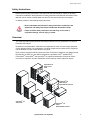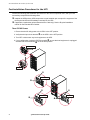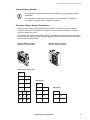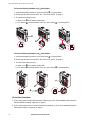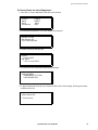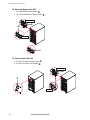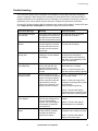
1
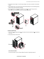
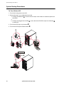
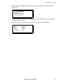
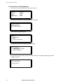
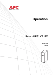
®
Symmetra LX
200/208/230 V, 4–16 kVA
Start Up Guide
®
Symmetra LX
Rack-mount UPS
Symmetra® LX
Rack-mount
Extended Run
Symmetra® LX
Tower UPS
Symmetra® LX
Tower
Extended Run
®
®
w w w. a p c . c o m
990-1541, English, January 2004
Safety Instructions
Safety Instructions
Before performing any procedures in this manual for the Symmetra® LX, adhere to all safety
instructions contained in the Symmetra® LX Safety Instructions and General Information Guide.
Manuals can be viewed or downloaded from the APC web site at www.apc.com/support.
In addition, adhere to the following safety instructions.
• Read, understand and follow ALL safety instructions contained in the
Symmetra® LX Safety Instructions and General Information Guide.
Electrical
Hazard
• Failure to follow safety instructions and warnings could result in
equipment damage, serious injury, or death.
Overview
This manual provides post-instruction and startup instructions for the Symmetra® LX UPS and
Extended Run Cabinet.
Illustrations are representative. Illustrations are applicable for tower and rack-mount equipment
unless otherwise noted. Your configuration, including components and optional APC equipment,
may be different from the models shown in this guide.
Entire contents copyright© 2004 by American Power Conversion Corporation. All rights reserved.
Reproduction in whole or in part without permission is prohibited. APC®, InfraStruXure®,
PowerChute®, Smart-UPS®, and Symmetra® are registered trademarks of American Power
Conversion Corporation. All other trademarks are the property of their respective owners.
Symmetra® LX
Rack-mount
UPS
Symmetra® LX
Rack-mount
Extended Run Cabinet
Symmetra® LX
Tower UPS
Symmetra® LX
Tower
Extended Run Cabinet
Symmetra® LX Start Up Guide
1
Post-Installation Procedures for the UPS
Post-Installation Procedures for the UPS
Perform the following post-installation procedures for the UPS in sequential order; after you have
successfully completed the following tasks:
# Installed the UPS and any UPS components not pre-installed upon receipt of the equipment. See
the Physical and Electrical Installation manuals for the UPS.
# If applicable, installed the optional Extended Run Cabinet(s). See the Physical Installation
manual for the Extended Run Cabinet.
Turn Off All Power
1. Ensure that the AC utility power to the UPS is in the OFF position.
2. Verify that the input circuit breaker , on the UPS is in the OFF position.
3. Turn OFF or disconnect any load equipment to the UPS.
4. If your configuration includes UPS PDU panel(s) -; ensure that load equipment is unplugged
and that PDU circuit breakers . are in the OFF position.
220/230/240 V
,
,
200/208 V
220/230/240 V
.
-
-
200/208 V
220/230/240 V
.
2
.
Symmetra® LX Start Up Guide
Post-Installation Procedures for the UPS
Connect Battery Modules
• Your configuration may have battery modules installed in B1 and B2 battery module
orientations.
Note
• B1 and B2 battery modules orientations are the exact Symmetra® LX battery but
are installed in the equipment in a different orientation.
Determine Battery Module Orientations:
Determine which battery module orientation procedure (B1 or B2) to use to connect battery
modules in the UPS. It is critical that you follow the correct connection method for your battery
module orientation (B1 or B2).
The diagrams below denote UPS configurations for available power module bays (P) and battery
modules bays (B1 and B2) in the UPS. B1 and B2 battery module orientations shown below are in
the Disconnect or Open position.
.
B1 Battery Module Orientation Disconnect or Open Position
B2 Battery Module Orientation Disconnect or Open Position
Extended Run UPS (16 kVA)
P
P
B1
P
B1
P
B1
P
P
B1
P
B1
UPS (16 kVA)
UPS (8 kVA)
B2
B2
B2
P
B1
P
B2
B2
B2
P
B1
P
B1
B2
B2
B2
P
B1
P
B1
Symmetra® LX Start Up Guide
3
Post-Installation Procedures for the UPS
To Connect Battery Modules in B1Orientation:
1. Verify that the battery module is in the Disconnect , or Open position.
2. Ensure that all power is turned OFF. See “Turn Off All Power” on page 2.
3. To connect the battery module:
a. Insert a coin - in the battery module dial.
b. Turn the dial . counterclockwise until it is in the Connect / or Closed position.
/
,
Pb
Pb
.
To Connect Battery Modules in B2 Orientation:
1. Verify that the battery module is in the Disconnect , or Open position.
2. Ensure that all power is turned OFF. See “Turn Off All Power” on page 2.
3. To connect the battery module:
a. Insert a coin - in the battery module dial.
b. Turn the dial . counterclockwise until it is in the Connect / or Closed position.
,
/
.
Go to Next Procedure
1 . If your configuration includes Extended Run Cabinets, go to the “Post-Installation Procedures for
the Extended Run Cabinet (Optional)” on page 5.
2 . If your configuration doesn’t include Extended Run Cabinets, go to the “Post-Installation System
Checklist Procedures,” beginning on page 8.
4
Symmetra® LX Start Up Guide
Post-Installation Procedures for the Extended Run Cabinet (Optional)
Post-Installation Procedures for the Extended Run Cabinet (Optional)
Connect Battery Modules
If you configuration includes installed Extended Run Cabinet(s), perform the following postinstallation procedures.
• Extended Run Cabinet battery modules are installed in the B2 battery module
orientation.
Note
• B1 and B2 battery modules orientations are the exact Symmetra® LX battery but
are installed in the equipment in a different orientation.
Battery Module Orientation:
Extended Run Cabinet battery modules are installed in the B2 battery module orientation.The
diagrams below denote Extended Run Cabinet configurations for available B2 battery modules
bays. B2 battery module orientations shown below are in the Disconnect or Open position.
9_Battery
Extended Run
B
B2 Battery
Module
Orientation Disconnect or
Open Position
2
B2
B
B
2
B2
B
2
B
2
B2
B
2
2
3-Battery
Extended Run
B
2
B2
B
2
To Connect Battery Modules in B2 Orientation:
1. Verify that the battery module is in the Disconnect , or Open position.
2. Ensure that all power is turned OFF. See “Turn Off All Power” on page 2.
3. To connect the battery module:
a. Insert a coin - in the battery module dial.
b. Turn the dial . counterclockwise until it is in the Connect / or Closed position.
,
/
.
Symmetra® LX Start Up Guide
5
Post-Installation Procedures for the Extended Run Cabinet (Optional)
Install the Door
1 . Install the door D by aligning the tabs E on the bottom of the door with the slots F on the bottom
of the frame.
2 . Gently snap the door into the frame.
.
,
L
-
Install and Connect the Battery Connector Plug
Due to it’s weight, only one tower Extended Run Cabinet can be stacked on top
of another tower UPS or another tower Extended Run Cabinet.
Caution
• Extended Run Cabinet dial numbers must be numbered sequentially; starting
with number 2.
Note
• Your configuration may be different than the examples shown for steps 1 and 2.
1. If your configuration only includes one Extended Run Cabinet.
a. Remove the screw and UPS battery connector panel D as shown.
b. Insert the Extended Run Cabinet battery connector E plug into the UPS battery
connector F slot.
c. Ensure that the Extended Run Cabinet dial number G is set to number 2.
d. If applicable, plug the communications cable into the Extended Run Cabinet communications
card H and the UPS communications card I. See page 7.
/
.
,
-
6
Symmetra® LX Start Up Guide
Post-Installation Procedures for the Extended Run Cabinet (Optional)
1
/
,
0
.
2 . If your configuration includes an additional Extended Run Cabinet:
a. Remove the screw and UPS battery connector panel D as shown.
b. Insert the primary Extended Run Cabinet battery connector E plug into the UPS battery
connector F slot.
c. Ensure that the Extended Run Cabinet dial number G is set to number 2.
d. Daisy chain the additional Extended Run battery connector H plug into the first Extended
Run Cabinet battery connector I slot.
e. Ensure that the additional Extended Run Cabinet dial number J is set to number 3.
G
J
D
F
H
I
E
Go to Next Procedure
Go to the “Post-Installation System Checklist Procedures,” beginning on page 8.
Symmetra® LX Start Up Guide
7
Post-Installation System Checklist Procedures
Post-Installation System Checklist Procedures
Complete the tasks in the system checklist to ensure that the UPS is properly installed.
Refer to the Symmetra® LX Physical Installation Manual and the Symmetra® LX
Electrical Installation Manual for detailed information concerning the steps
outlined in the checklist procedures.
Note
UPS System Checklist
1 . Ensure that the “Post-Installation Procedures for the UPS,” beginning on page 2 are successfully
completed.
2 . If your configuration includes Extended Run Cabinet(s), ensure that the “Post-Installation
Procedures for the Extended Run Cabinet (Optional),” beginning on page 5 are successfully
completed.
3 . If your equipment is installed in a rack, ensure that all components are securely mounted.
4 . Ensure that all modules (power, battery, and intelligence) are fully installed.
5 . Check that the PowerView is connected to the primary Intelligence Module (IM).
6 . Turn ON the AC utility power to the UPS.
7 . Turn ON the Input Circuit Breaker D and System Enable E switches.
8 . The system will make some clicking sounds as it powers up, and may display fault messages on
the PowerView display. Disregard the messages at this time. Press the 'Esc' button until the
Monitoring screen is displayed.
9 . Turn the Maintenance Bypass F switch ON.
220/230/240 V
,
-
200/208 V
.
,
10.Disregard any LED indicators or messages on the PowerView. Press the 'Esc' button until the
monitoring screen is displayed.
8
Symmetra® LX Start Up Guide
Post-Installation System Checklist Procedures
11.Verify that the input voltage, Vin, and the output voltage, Vout, match your branch circuit (mains)
voltage.
12.Test the REPO switch. The System Enable switch should physically move to the Standby position,
and the system should shut down completely.
13.If all prior checks are completed, the installation is successful. Turn OFF the Input Circuit
Breaker /, System Enable 0, and Maintenance Bypass 1 switches.
220/230/240 V
/
200/208 V
0
/
1
Install the UPS Door
1 . Install the door , by aligning the tabs - on the bottom of the door with the slots . on the bottom
of the frame.
2 . Gently snap the door into the frame.
,
.
L
-
Go to Next Procedure
To start up the system, go to the “System Startup Procedures,” beginning on page 10.
Symmetra® LX Start Up Guide
9
System Startup Procedures
System Startup Procedures
To Turn ON the UPS
1 . Turn ON AC utility power to the UPS.
2 . Perform this step if your configuration has loads.
a. If load(s) are hardwired ,, ensure that each output circuit breaker in distribution panels are
turned ON.
or
b. If load(s) are plugged into the UPS -, ensure that each UPS PDU output circuit breaker .
is turned ON.
3 . Turn ON the UPS input circuit breaker /.
4 . Turn ON the UPS System Enable switch 0.
0
.
,
-
220/230/240 V
/
/
200/208 V
10
Symmetra® LX Start Up Guide
System Startup Procedures
5 . After initialization, the Monitoring Screen appears, providing a concise view of key operating
parameters.
Chg100% Load 000% --------220 Vin 000 Vout 60Hz
Runtime: 00hr 30min
6 . At the Monitoring screen, press any navigation key to open the Main Menu. This menu provides
access to various submenus.
7 . To open a submenu, move the selection arrow to its item and press the ENTER key.
>Control
Status
Setup
Accessories
Logging
Display
Diags
Help
Symmetra® LX Start Up Guide
11
System Startup Procedures
To Power UP the Load Equipment
1. Use ‘ESC’ to view to Main Menu and then select Control.
>Control
Status
Setup
Accessories
Logging
Display
Diags
Help
2. Scroll down and select the Turn UPS Output On command.
Graceful Turn Off
Start Runtime Cal
>Turn UPS Output On
3. Confirm choice by selecting Yes.
Confirm:
Turn UPS ON
CANCEL
> YES, Turn UPS ON
4. You will hear some clicking sounds and see message.
UPS HAS BEEN
COMMANDED TO TURN
LOAD POWER ON
5. In approximately 90 seconds, you will see the UPS Load is On message, and the green status
indicator will be On.
UPS LOAD IS ON
Press any key...
12
Symmetra® LX Start Up Guide
System Startup Procedures
To Power Down the Load Equipment
1. Use ‘ESC’ to view to Main Menu and then select Control.
>Control
Status
Setup
Accessories
Logging
Display
Diags
Help
2. Scroll down and select the Turn UPS Output Off command.
Graceful Turn Off
Start Runtime Cal
>Turn UPS Output Off
3. Confirm choice by selecting Yes.
Confirm:
Turn UPS OFF
NO, Abort
> YES, Turn UPS OFF
4. You will hear some clicking sounds and see message.
UPS HAS BEEN
COMMANDED TO TURN
LOAD POWER OFF
5. In approximately 90 seconds, you will see the UPS Load is Off message, and the green status
indicator will be On.
UPS LOAD IS OFF
Press any key...
Symmetra® LX Start Up Guide
13
System Startup Procedures
To Manually Bypass the UPS
1. Turn ON the Input Circuit Breaker ,.
2. Turn ON the Maintenance Bypass switch -.
220/230/240 V
,
,
200/208 V
-
To Power Down the UPS
1. Turn OFF the System Enable switch ,.
2. Turn OFF the Input Circuit Breaker -.
220/230/240 V
-
-
,
200/208 V
14
Symmetra® LX Start Up Guide
Troubleshooting
Troubleshooting
The PowerView reports various messages on the display, including alarm status and changes in
system configuration. Basic startup error messages are listed below. Refer to the Symmetra® LX
Operations Manual for the complete list of error messages. The operations manual also contains an
explanation of the various display screens and how to navigate and operate the PowerView.
Contact APC Technical Support Staff for assistance with complex UPS problems. Visit the APC Web
site at http://www.apc.com/support for technical support and contact numbers.
PowerView Message
Meaning
#Pwr modules changed
since last ON.
At least one power module has No corrective action necessary.
been added or removed from Proceed with the startup.
the UPS since the last time the
Pwr ON command was issued.
#Batteries changed since
last ON.
At least one battery module
has been added or removed
from the UPS since the last
time the Pwr ON command
was issued.
No corrective action necessary.
Proceed with the startup.
No Redundant Intelligence
Module (IM).
There is no redundant
intelligence module installed
and working.
Proceed with the startup or abort
the startup and install anew
IM.Note: Without two functioning
IMs, there is no redundancy in the
event of an IM failure.
Batt capacity less than
Return Batt Cap.
The battery capacity of the
UPS is less than the user
specified minimum battery
capacity required to turn on
the load.
Option 1: Abort the startup and
allow batteries to recharge.
The input frequency to the
UPS is outside the configured
range. The output frequency
will not synchronize with the
input frequency. Normal
bypass is not available. The
system will start on-battery.
Option 1: Improve the frequency of
the incoming voltage.
Input Freq outside
configured range.
Corrective Action
Option 2: Continue startup, with
less than minimum battery capacity.
Option 2: Widen the range of the
acceptable incoming frequency with
the PowerView.
(Startup>Setup>OuputFreq)
Option 3: Proceed with startup.
Normal bypass is not available and
system may start on battery power.
AC adequate for UPS but
not for bypass.
The UPS will function on-line
with the input voltage, but in
the event that bypass is
required, the input voltage is
not adequate to power the
load equipment.
Low/No AC input, startup on Input voltage is not adequate
battery.
to start the UPS. If startup
proceeds, the UPS will
function from battery.
Symmetra® LX Start Up Guide
Option 1: Improve the incoming
voltage.
Option 2: Proceed with startup.
Normal bypass is not available.
Option 1: Abort startup until
acceptable input voltage is present.
Option 2: Proceed with startup.
Battery will be discharged.
15
Troubleshooting
16
Symmetra® LX Start Up Guide