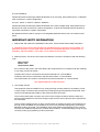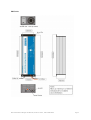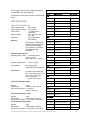
1
© 2007
Universal Power Charger
12volt & 24volt VERSIONS FOR SPECIALIST VEHICLES
Instructions for
installation and use
Type approved E13*3027*00
COMPLIANCE INFORMATION
UNPACKING
APPLICATION
IMPORTANT SAFETY INFORMATION
FM 37786
ISO 9001:2000
Antares (Europe) Limited
Chiltern Hill . Chalfont St Peter
Gerrards Cross . Bucks . SL9 9UQ . UK
Tel: +44 (0)1753 890888
Fax: +44 (0)1753 891260
email: [email protected]
INSTALLATION
OPERATION
SPECIFICATION
RECYCLING INFORMATION
www.antares.co.uk
UPC Universal Power Charger User Manual, Part No 13142-01, 12th October 2007
SUPPORT
Page 1
COMPLIANCE INFORMATION
CE mark:
Conditions of use for which CE mark applies
This equipment is intended to be used solely for professional purposes in commercial and light
industrial locations, powered from the low-voltage public mains supply.
Non approved conditions of use
This unit may be suitable for use in other applications, but it can only be supplied as a component in
this respect, for which the CE mark displayed on this manual does not apply. If the unit is used in this
way, as a component part to build a battery charging or similar apparatus, then this unit is supplied
solely on the condition that it is the responsibility of the manufacturer of the charging apparatus to
ensure that the apparatus complies with the requirements of the relevant legislation, and apply the
CE marking should it be required. In this case, this user manual does not apply, and reference
should be made to Antares (Europe) Limited for any information required for compliance with the
legislation.
Type approval:
This product is type approved for automotive applications.
UNPACKING
Pack contents:
1 Antares Universal Power Charger
1 Instructions for Installation & Use*
*with multiple shipments this manual may be shipped separately, further copies can be
obtained from Antares (Europe) Limited or downloaded from our support website (registration
required for access):
http://www.antares.co.uk/technical/index.htm
APPLICATION
The Power Charger is suitable for use under shelter only. It must not be exposed to rain. It is suitable
for a wide range of applications on vehicles or in fixed locations, subject to the conditions of use
stated above under CE marking & type approval. It may be used as a stand alone high performance
DC power supply (specify on order), or as a fully automatic multistage charger when connected to a
battery. The charging characteristics of the standard model are optimised for flooded and retained
electrolyte lead acid batteries. Other charging regimes are available & may be customised for
specific applications.
Please ensure that operation is confined to within the limits contained in the product specification
given at the end of this manual.
Suitable Battery Types:
The power charger is suitable for charging the following types of battery:
12 VOLT MODELS:
Flooded and retained electrolyte lead acid batteries of 12 volt rating, being made up from 6 identical
cells connected in a series configuration.
UPC Universal Power Charger User Manual, Part No 96550-96580, 12th October 2007
Page 2
24 VOLT MODELS:
Flooded and retained electrolyte lead acid batteries of 24 volt rating, being made up from 12 identical
cells connected in a series configuration.
36 VOLT, 48VOLT, 72VOLT & 96VOLT MODELS
Flooded and retained electrolyte lead acid batteries of the same voltage rating, being made up from
identical 2 volt cells connected in a series configuration, or banks of 6 identical cells (ie identical 12
volt packs) connected in a series configuration.
No attempt should be made to charge non-rechargeable batteries with this unit, as a hazard could
result.
IMPORTANT SAFETY INFORMATION
1. Please read and observe the installation instructions, which contain further safety information.
2. WARNING: EXPLOSIVE GASSES MAY BE GENERATED BY A BATTERY ON CHARGE. TO
PREVENT IGNITION, ALLOW TIME FOR GASSES TO DISPERSE BEFORE ATTEMPTING TO
CONNECT OR DISCONNECT THIS UNIT TO OR FROM THE BATTERY.
3. Statutory Notice: The wires in the mains input lead are coloured in accordance with the following
code:
Blue: Neutral
Brown: Live
Green/Yellow: Earth
If the colours of the wires in the mains lead of this equipment do not correspond with the markings
in your plug, proceed as follows:
The Blue wire must be connected to the terminal marked N or coloured Black.
The Brown wire must be connected to the terminal marked L or coloured Red.
The Green/Yellow wire must be connected to the terminal marked E or coloured Green.
THIS EQUIPMENT MUST BE EARTHED
4. Low Voltage Circuits
This equipment must be installed in such a way that high currents present in any battery circuits
or other output connections are prevented from flowing through the equipment mains lead. Such
currents could damage the integrity of the protective earth connection.
The incoming mains earth connects only to the Power Charger enclosure. Both the earth and
enclosure are isolated from all Power Charger output circuits, which helps the above requirement
to be achieved.
The low output voltage from the 12 & 24 volt units does not present an electric shock hazard, but
the high current available can be hazardous by virtue of its potential heating effect, particularly if
batteries are also connected. The installation wiring must therefore be adequate for the currents
involved, with suitable protection from potential fault conditions. Accidental bridging of high energy
circuits by users (eg by jewellery) must be prevented.
UPC Universal Power Charger User Manual, Part No 13142-01, 12th October 2007
Page 3
5. Special notes for 48V, 72V and 96V chargers
THE BATTERY & OUTPUT VOLTAGE ASSOCIATED WITH THESE CHARGERS PRESENTS
AN ELECTRIC SHOCK HAZARD.. THE INSTALLER/USER MUST BE FAMILIAR WITH THE
REQUIREMENTS OF THE LOW VOLTAGE DIRECTIVE (AS ENACTED IN NATIONAL LAW)
BEFORE PROCEEDING WITH INSTALLATION & USE OF THIS EQUIPMENT.
Overview
The Universal Power Charger (UPC) family is one of the most compact battery chargers available. It
is supplied in three frame sizes, each covering a range of power outputs: UPC800, UPC1600,
UPC3200.
Each series shares the same control system and operates in the same way. They differ in their
method of mounting and the size of the power stage.
INSTALLATION
Choose a location where the unit will not be subjected to water spray, dust, or insect ingress.
Locations subjected to high temperature or vibration must be avoided if performance and reliability
are not to be impaired.
The power system may be mounted in any orientation, but ensure that there is sufficient clearance
around the unit to allow air to enter and leave without undue restriction (25 to 30mm clearance is
sufficient). Any possibility of the air vents becoming accidentally obstructed should be prevented.
Ideally, the unit should be located in the same area as the load equipment or battery in order to
minimise voltage drop in the DC output leads, and also to ensure that the Power Charger
temperature compensating charge system samples air with the same temperature as the batteries. If
a similar operating temperature environment cannot be provided, then a remote temperature/voltage
sensor is available as an option.
Mounting
800 series
Integral flanges are provided for ease of mounting in situations where the unit needs to be
secured to prevent movement, such as in vehicles. Ideally, the mounting should make electrical
contact with the vehicle bodywork.
1600 Series
Mounting is by means of either a bridging bracket mounted over the rubber shock absorber ends,
or via flanges on the end brackets.
3200 Series
The charger can be used positioned horizontally on a table or a shelf, hung on a wall using the
free supplied bracket, or as a built in charger in the vehicle. When it is built into a vehicle it will
usually need to be attached using anti-vibration mounts. The charger can be either directly
connected to the battery, or with suitably sized DC connectors.
UPC Universal Power Charger User Manual, Part No 96550-96580, 12th October 2007
Page 4
800 Series
UPC Universal Power Charger User Manual, Part No 13142-01, 12th October 2007
Page 5
1600 Series
UPC Universal Power Charger User Manual, Part No 96550-96580, 12th October 2007
Page 6
3200 Series
UPC Universal Power Charger User Manual, Part No 13142-01, 12th October 2007
Page 7
Connections
Mains Connection
This equipment is designed for connection to public low-voltage single phase AC mains supplies. It is
built to insulation class 1, and so must be earthed. The input voltage range for each model is given in
the product specification at the end of this manual.
The wires in the mains input lead are coloured in accordance with the following code:
Blue: Neutral
Brown: Live
Green/Yellow: Earth
The unit is equipped with a mains input fuse, located inside the unit. Rupture of this fuse is indicative
of a unit fault; it is not a user serviceable item.
The unit’s input current permits mains connection of the UPC800 & UPC1600 models via an
appropriate non-reversible mains plug if desired. If a standard UK domestic plug is used, it should be
fitted with a 10 amp fuse. The input current of the UPC3200 exceeds the capacity of the UK domestic
plug, so a blue BS4343 industrial plug or a hard-wired connection is required.
Local regulations, or regulations applicable to the intended application of this product, may override
or impose additional requirements, which must be taken into account. Attention is drawn to the
requirement for residual current circuit breakers in some vehicular applications.
Output Connections
WARNING: EXPLOSIVE GASSES MAY BE GENERATED BY A BATTERY ON
CHARGE. TO PREVENT IGNITION, ALLOW TIME FOR GASSES TO DISPERSE
BEFORE ATTEMPTING TO CONNECT OR DISCONNECT THIS UNIT TO OR
FROM THE BATTERY.
The Power Charger is normally supplied with two flying leads for the DC power output. The heavy
gauge red lead is the connection to system positive, and the black lead to negative. Positive,
negative or isolated chassis circuits may be connected. Be sure to disconnect the input supply before
making or removing the connections to the battery.
Ideally, in battery charging applications, both the positive and negative leads should be routed
directly to the battery terminals. This ensures that the Power Charger system responds only to the
battery conditions, without being disturbed by other connected equipment. The unit is suitable for
permanent connection to the battery.
If a temporary connection is made to an automobile battery whilst in situ, proceed as follows:
•
•
•
•
Ensure that the AC input supply is disconnected.
Then connect the appropriate output conductor to the battery terminal which does not
connect to the vehicle chassis (normally positive on negative earth vehicles), then
connect the other output conductor to the battery terminal which connects to the vehicle
chassis.
Connect the AC input supply.
To stop charging, disconnect the AC input supply, wait for gasses to disperse, then
remove the battery connections in reverse order.
The leads may be shortened if required.
If longer leads are required, the leads supplied can be replaced or lengthened, using suitable cable,
up to a maximum extended length of around 5 metres. Systems with extended cables will benefit
UPC Universal Power Charger User Manual, Part No 96550-96580, 12th October 2007
Page 8
greatly from the remote sense option, which eliminates the effect of voltage drop in the supply
cables. Suitable cable sets & the “plug-in” remote sensor can be supplied by Antares (Europe)
Limited if required.
OPERATION
The Power Charger system is fully automatic in operation.
The charger is supplied with a standard control software providing the charging regime shown above.
The charger is pre-programmed with other software regimes which are user selectable, but these
should be used with caution. Please contact Antares (Europe) Limited for advice.
UPC Universal Power Charger User Manual, Part No 13142-01, 12th October 2007
Page 9
The charging regime in the standard program is
as indicated in the above diagram.
Model range & part numbers
The operation of the LED indicator is as indicated
above.
12V
SPECIFICATIONS
Technical Data All Series
Input voltage range:
Input frequency range:
Power factor
Rated Voltage
Protection
90V—255V
45 to 400Hz
~1 (power factor
corrected)
12V, 24V, 36V, 48V,
72V, 96V
IP21 (when fitted
horizontally)
General
Temperature controlled fan
Reverse polarity protection
Short Circuit protection
CE certified in accordance
with applicable EN
standards.
Climatic specifications:
Operating temp range:···· Full output power:
-25°C to +40°C
(UPC 3200 -5° to +40°C)
Storage Temperature: ···· -55°C to +85°C
IP Protection
IP21 (when fitted
horizontally) IP20 otherwise
Connection
DC Output connection RK
twin, 1.5m long, 6mm2 up to
30A, 10mm2 up to 50A,
16mm2 up to 60A,
····· 25mm2 up to 130A
Technical Data Series 800
Weight
1.5kg
Dimensions
L250 x B110 x H75 mm
AC Input Connection 3 x 0.75mm2,
approx 1.5m long
Technical Data Series 1600
Series
Specification
Part number
UPC800
12V/20A
96558
UPC800
12V/30A
96568
UPC800
12V/40A
96559
UPC800
12V/50A
96550
UPC1600
12V/60A
96560
UPC3200
12V/130A
96561
UPC3200
12V/200A
96562
UPC800
24V/20A
96563
UPC800
24V/30A
96551
UPC1600
24V/40A
96564
UPC1600
24V/60A
96565
UPC3200
24V/100A
96566
UPC3200
24V/127A
96567
UPC800
36V/20A
96569
UPC1600
36V/40A
96570
UPC3200
36V/95A
96571
UPC800
48V/15A
96572
UPC1600
48V/30A
96573
UPC3200
48V/64A
96574
UPC800
72V/10A
96575
UPC1600
72V/20A
96576
UPC3200
72V/40A
96577
UPC800
96V/8A
96578
UPC1600
96V/15A
96579
UPC3200
96V/30A
96580
ALL TYPES
Remote Panel
96590
24V
36V
48V
72V
96V
Weight
1.6kg
Dimensions
L280 x B125 x H80 mm
AC Input Connection 3 x 1.5, approx 1.5m long
Technical Data Series 3200
OPTIONS
ALL TYPES
Remote sense 2.5M
96591
Weight
12kg
Dimensions
L420 x B260 x H90 mm
AC Input Connection 3 x 2.5, approx 1.5m long
ALL TYPES
Remote Sense 20M
96593
ALL TYPES
Power Supply Conversion 96592
UPC Universal Power Charger User Manual, Part No 96550-96580, 12th October 2007
Page
UPC OPTIONS
Remote Temperature and Voltage Sensor
The diagram below shows the method of connection of the sensor. The purpose of the sensor is to
compensate for the voltage drop in the battery supply cables and to compensate for the battery
temperature to ensure that the optimal voltage is applied to the terminals.
Two kits are available which differ in length, 2.5m and 20m and should be selected depending on the
application. See diagram below for installation.
Remote LED Display
The display mimics the lamp on the charger allowing it to be located in an accessible position on the
dashboard or control panel.
Conversion to a Power Supply
The UPC can be used as a constant voltage power supply where no battery is connected. This
requires a change of program and is not configurable by the user. Please contact Antares for more
information or conversion.
UPC Universal Power Charger User Manual, Part No 13142-01, 12th October 2007
Page 11
RECYCLING INFORMATION
When this product reaches the end of its useful life, it should be disposed of in accordance with the
regulations in force in the place where the product is located.
This product is not encompassed within the scope of the UK Waste Electrical & Electronic Products
(WEEE) regulations; Antares (Europe) Limited is not liable for the cost of collection & re-cycling of
the materials contained within the equipment.
When installed on a vehicle, it may lie within the scope of the End-of-Life Vehicles Regulations, in
which case the original vehicle producer may bear the responsibility for re-cycling.
In most cases, local regulations will prohibit disposal in land-fill sites. If so, the equipment should be
handed to an appropriately licensed waste management organisation.
Antares (Europe) Limited is able to offer disposal & recycling facilities through its recycling scheme
operator, B2B Compliance, who should be approached in the first instance. There will be a charge
for collection & disposal.
B2B Compliance may be contacted by telephone: (+44) 1691 676124.
SUPPORT
Returns
Use of the Universal Power Charger should be trouble free. In the event that problems occur please
call one of our support team on 01753 890888. Should it be necessary to send the unit to us for repair please photocopy the return form on the next page or download the form from our website
www.antares.co.uk.
Applications engineering
Antares have an experienced team of engineers who are happy to discuss the integration of the UPC
into the application.
Products to complete the installation
We offer a wide range of additional products for use with the UPC range:
CYCLIC DUTY GEL BATTERIES SUITABLE FOR REPEATED CHARGING
VEHICLE AC INLET SOCKETS WITH DRIVE-AWAY PROTECTION
DC ACCESSORIES INCLUDING FUSES, CABLES, CONNECTORS
VEHICLE DC INLET SOCKETS FOR EXTERNAL CHARGING
Further details of all of our products can be found on our website www.antares.co.uk or by calling us
on 01753 890888.
UPC Universal Power Charger User Manual, Part No 96550-96580, 12th October 2007
Page
Antares (Europe) Limited
Chiltern Hill
Chalfont St Peter
Gerrards Cross
Buckinghamshire
SL9 9UQ UK
www.antares.co.uk
Tel: +44 (0) 1753 890888
Fax: +44 (0) 1753 891260
T PRODUCT RETURNS FORM M
T ADVANCE REPLACEMENT RETURNS FORM
Date
(TICK BOX ABOVE TO INDICATE TYPE OF RETURN)
PLEASE USE THIS FORM TO ACCOMPANY RETURNS TO ANTARES (EUROPE) LIMITED. This will
enable us to expedite your repair/return more efficiently. If you have your own return form, please
attach it to this form. After receipt of your return we will either repair or replace the unit if within our
warranty. If outside our warranty, we will provide a written quotation for repair/replacement. Please
note that in the case of a ‘no fault found’ or the repair does not proceed, then a charge of £25 ex VAT
and return carriage (if required) is payable. Goods arriving without suitable paperwork will take longer
to process.
Contact
Company Name
Delivery Address (for return)
Part Number
Serial Number
Product Description
Vehicle Type
Registration/your reference
Contact Fax
Contact Tel
Reason for return
(
(
(
(
(
(
(
)
)
)
)
)
)
)
Advance replacement returned for credit against invoice ..… RA ………
Incorrect supply
Please repair under warranty (Invoice date ……/……/……)
Please quote for repair
Please repair – purchase order attached ( )
Not required (note there may be a restocking charge)
Unit for reconditioning (advance replacement RA# ………………)
Description of observed fault and additional relevant information
UPC Universal Power Charger User Manual, Part No 13142-01, 12th October 2007
Page 13