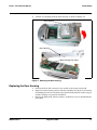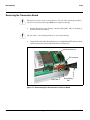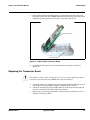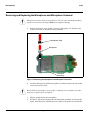
1
Level 1 and 2 Service Manual V150 Dual Band Wireless Telephone GSM 900/DCS 1800MHz with GPRS Level 1 and 2 Service Manual 1 and 2 V150 6809471A67-O Introduction . . . . . . . . . . . . . . . . . . . . . . . . . . . . . . . . . . . . . . . . . . . . . . . . . . . . . . . . . . . . . . . . . . . . . . . . . . . . . . 5 Product Identification . . . . . . . . . . . . . . . . . . . . . . . . . . . . . . . . . . . . . . . . . . . . . . . . . . . . . . . . . . . . . . . . 5 Product Names . . . . . . . . . . . . . . . . . . . . . . . . . . . . . . . . . . . . . . . . . . . . . . . . . . . . . . . . . . . . . . . . . . . . . 5 Product Changes . . . . . . . . . . . . . . . . . . . . . . . . . . . . . . . . . . . . . . . . . . . . . . . . . . . . . . . . . . . . . . . . . . . . 5 Regulatory Agency Compliance . . . . . . . . . . . . . . . . . . . . . . . . . . . . . . . . . . . . . . . . . . . . . . . . . . . . . . . . 5 Computer Program Copyrights . . . . . . . . . . . . . . . . . . . . . . . . . . . . . . . . . . . . . . . . . . . . . . . . . . . . . . . . 6 About This Service Manual . . . . . . . . . . . . . . . . . . . . . . . . . . . . . . . . . . . . . . . . . . . . . . . . . . . . . . . . . . . 6 Warranty Service Policy . . . . . . . . . . . . . . . . . . . . . . . . . . . . . . . . . . . . . . . . . . . . . . . . . . . . . . . . . . . . . . 7 Parts Replacement . . . . . . . . . . . . . . . . . . . . . . . . . . . . . . . . . . . . . . . . . . . . . . . . . . . . . . . . . . . . . . . . . . 7 Specifications . . . . . . . . . . . . . . . . . . . . . . . . . . . . . . . . . . . . . . . . . . . . . . . . . . . . . . . . . . . . . . . . . . . . . . . . . . . 9 Product Overview . . . . . . . . . . . . . . . . . . . . . . . . . . . . . . . . . . . . . . . . . . . . . . . . . . . . . . . . . . . . . . . . . . . . . . . . 11 Features . . . . . . . . . . . . . . . . . . . . . . . . . . . . . . . . . . . . . . . . . . . . . . . . . . . . . . . . . . . . . . . . . . . . . . . . . . 11 General Operation . . . . . . . . . . . . . . . . . . . . . . . . . . . . . . . . . . . . . . . . . . . . . . . . . . . . . . . . . . . . . . . . . . . . . . . . 14 Controls, Indicators, and Input / Output (I/O) Connectors . . . . . . . . . . . . . . . . . . . . . . . . . . . . . . . . . 14 User Interface Menu Structure . . . . . . . . . . . . . . . . . . . . . . . . . . . . . . . . . . . . . . . . . . . . . . . . . . . . . . . 16 Alert Settings . . . . . . . . . . . . . . . . . . . . . . . . . . . . . . . . . . . . . . . . . . . . . . . . . . . . . . . . . . . . . . . . . . . . . 16 Battery Information . . . . . . . . . . . . . . . . . . . . . . . . . . . . . . . . . . . . . . . . . . . . . . . . . . . . . . . . . . . . . . . . 17 Operation . . . . . . . . . . . . . . . . . . . . . . . . . . . . . . . . . . . . . . . . . . . . . . . . . . . . . . . . . . . . . . . . . . . . . . . . . 21 Tools and Test Equipment . . . . . . . . . . . . . . . . . . . . . . . . . . . . . . . . . . . . . . . . . . . . . . . . . . . . . . . . . . . . . . . . . 23 Disassembly . . . . . . . . . . . . . . . . . . . . . . . . . . . . . . . . . . . . . . . . . . . . . . . . . . . . . . . . . . . . . . . . . . . . . . . . . . . . . 24 Removing the Battery Cover and Battery . . . . . . . . . . . . . . . . . . . . . . . . . . . . . . . . . . . . . . . . . . . . . . . 24 Replacing the Battery and Battery Cover . . . . . . . . . . . . . . . . . . . . . . . . . . . . . . . . . . . . . . . . . . . . . . . 25 Removing the SIM Card . . . . . . . . . . . . . . . . . . . . . . . . . . . . . . . . . . . . . . . . . . . . . . . . . . . . . . . . . . . . . 26 Replacing the SIM Card . . . . . . . . . . . . . . . . . . . . . . . . . . . . . . . . . . . . . . . . . . . . . . . . . . . . . . . . . . . . . 26 Removing and Replacing the Antenna . . . . . . . . . . . . . . . . . . . . . . . . . . . . . . . . . . . . . . . . . . . . . . . . . 27 Removing and Replacing the Light Guide . . . . . . . . . . . . . . . . . . . . . . . . . . . . . . . . . . . . . . . . . . . . . . . 28 Removing the Rear Housing . . . . . . . . . . . . . . . . . . . . . . . . . . . . . . . . . . . . . . . . . . . . . . . . . . . . . . . . . 30 Replacing the Rear Housing . . . . . . . . . . . . . . . . . . . . . . . . . . . . . . . . . . . . . . . . . . . . . . . . . . . . . . . . . . 31 Removing the Transceiver Board . . . . . . . . . . . . . . . . . . . . . . . . . . . . . . . . . . . . . . . . . . . . . . . . . . . . . . 32 Replacing the Transceiver Board . . . . . . . . . . . . . . . . . . . . . . . . . . . . . . . . . . . . . . . . . . . . . . . . . . . . . . 33 Removing and Replacing the Microphone and Microphone Grommet . . . . . . . . . . . . . . . . . . . . . . . . . 34 Removing and Replacing the Keypad PCB . . . . . . . . . . . . . . . . . . . . . . . . . . . . . . . . . . . . . . . . . . . . . . 35 Removing and Replacing the Keypad Keys . . . . . . . . . . . . . . . . . . . . . . . . . . . . . . . . . . . . . . . . . . . . . . 36 Removing the Flip Assembly . . . . . . . . . . . . . . . . . . . . . . . . . . . . . . . . . . . . . . . . . . . . . . . . . . . . . . . . . 36 SIM Card and Identification . . . . . . . . . . . . . . . . . . . . . . . . . . . . . . . . . . . . . . . . . . . . . . . . . . . . . . . . . . . . . . . . 37 Live SIM Card . . . . . . . . . . . . . . . . . . . . . . . . . . . . . . . . . . . . . . . . . . . . . . . . . . . . . . . . . . . . . . . . . . . . . 37 Personality Transfer . . . . . . . . . . . . . . . . . . . . . . . . . . . . . . . . . . . . . . . . . . . . . . . . . . . . . . . . . . . . . . . . 37 Identification . . . . . . . . . . . . . . . . . . . . . . . . . . . . . . . . . . . . . . . . . . . . . . . . . . . . . . . . . . . . . . . . . . . . . . 39 Troubleshooting . . . . . . . . . . . . . . . . . . . . . . . . . . . . . . . . . . . . . . . . . . . . . . . . . . . . . . . . . . . . . . . . . . . . . . . . . 41 Manual Test Mode . . . . . . . . . . . . . . . . . . . . . . . . . . . . . . . . . . . . . . . . . . . . . . . . . . . . . . . . . . . . . . . . . 41 Manual Test Mode Commands . . . . . . . . . . . . . . . . . . . . . . . . . . . . . . . . . . . . . . . . . . . . . . . . . . . . . . . . 41 Troubleshooting Chart . . . . . . . . . . . . . . . . . . . . . . . . . . . . . . . . . . . . . . . . . . . . . . . . . . . . . . . . . . . . . . 42 Programming: Software Upgrade and Flexing . . . . . . . . . . . . . . . . . . . . . . . . . . . . . . . . . . . . . . . . . . . 45 Part Number Charts . . . . . . . . . . . . . . . . . . . . . . . . . . . . . . . . . . . . . . . . . . . . . . . . . . . . . . . . . . . . . . . . . . . . . . . 46 Exploded View Diagram . . . . . . . . . . . . . . . . . . . . . . . . . . . . . . . . . . . . . . . . . . . . . . . . . . . . . . . . . . . . . 46 Exploded View Parts List . . . . . . . . . . . . . . . . . . . . . . . . . . . . . . . . . . . . . . . . . . . . . . . . . . . . . . . . . . . 47 Accessories and Related Publications . . . . . . . . . . . . . . . . . . . . . . . . . . . . . . . . . . . . . . . . . . . . . . . . . . 48 6809471A67-O August 20, 2003 3 V150 4 August 20, 2003 Level 1 and 2 Service Manual 1 and 2 V150 6809471A67-O Introduction Introduction Motorola® Inc. maintains a worldwide organization that is dedicated to provide responsive, full-service customer support. Motorola products are serviced by an international network of company-operated product care centers as well as authorized independent service firms. Available on a contract basis, Motorola Inc. offers comprehensive maintenance and installation programs which enable customers to meet requirements for reliable, continuous communications. To learn more about the wide range of Motorola service programs, contact your local Motorola products representative or the nearest Customer Service Manager. Product Identification Motorola products are identified by the model number on the housing. Use the entire model number when inquiring about the product. Numbers are also assigned to chassis and kits. Use these numbers when requesting information or ordering replacement parts. Product Names Product names included in V150 telephones are listed on the front cover. Product names are subject to change without notice. Some product names, as well as some frequency bands, are available only in certain markets. Product Changes When electrical, mechanical or production changes are incorporated into Motorola products, a revision letter is assigned to the chassis or kit affected, for example; -A, -B, or -C, and so on. The chassis or kit number, complete with revision number is imprinted during production. The revision letter is an integral part of the chassis or kit number and is also listed on schematic diagrams and printed circuit board layouts. Regulatory Agency Compliance This device complies with Part 15 of the FCC Rules. Operation is subject to the following conditions: 1. This device may not cause any harmful interference, and 2. must accept interference received, including interference that may cause undesired operation. This class B device also complies with all requirements of the Canadian Interference-Causing Equipment Regulations (ICES-003). Cet appareil numérique de la classe B respecte toutes les exigences du Règlement sur le matériel brouilleur du Canada. 6809471A67-O August 20, 2003 5 Introduction 1 and 2 V150 6809471A67-O V150 Computer Program Copyrights The Motorola products described in this manual may include Motorola computer programs stored in semiconductor memories or other media that are copyrighted with all rights reserved worldwide to Motorola. Laws in the United States and other countries preserve for Motorola, Inc. certain exclusive rights to the copyrighted computer programs, including the exclusive right to copy, reproduce, modify, decompile, disassemble, and reverse-engineer the Motorola computer programs in any manner or form without Motorola's prior written consent. Furthermore, the purchase of Motorola products shall not be deemed to grant either directly or by implication, estoppel, or otherwise, any license or rights under the copyrights, patents, or patent applications of Motorola, except for a nonexclusive license to use the Motorola product and the Motorola computer programs with the Motorola product. About This Service Manual Using this service manual and the suggestions contained in it assures proper installation, operation, and maintenance of V150 Series telephones. Refer questions about this manual to the nearest Customer Service Manager. Audience This document aids service personnel in testing and repairing V150 telephones. Service personnel should be familiar with electronic assembly, testing, and troubleshooting methods, and with the operation and use of associated test equipment. Use of this document assures proper installation, operation, and maintenance of Motorola products and equipment. It contains all service information required for the equipment described and is current as of the printing date. Scope This document provides basic information relating to V150 Series telephones, and also provides procedures and processes for repairing the units at Level 1 and 2 service centers including: • Unit swap out • Repairing of mechanical faults • Basic modular troubleshooting • Testing and verification of unit functionality • Initiate warranty claims and send faulty modules to Level 3 or 4 repair centers. Conventions Special characters and typefaces, listed and described below, are used in this publication to emphasize certain types of information. ➧ 6 Note: Emphasizes additional information pertinent to the subject matter. August 20, 2003 6809471A67-O Level 1 and 2 Service Manual Introduction G E M Caution: Emphasizes information about actions which may result in equipment damage. Warning: Emphasizes information about actions which may result in personal injury. Keys to be pressed are represented graphically. For example, instead of “Press the Enter Key”, you will see “Press M”. Information from a screen is shown in text as similar as possible to what appears in the display. For example, ALERTS or ALERTS or ALERTS. Information that you need to type is printed in boldface type Warranty Service Policy The product will be sold with the standard 12 months warranty terms and conditions. Accidental damage, misuse, and extended warranties offered by retailers are not supported under warranty. Non warranty repairs are available at agreed fixed repair prices. Out of Box Failure Policy The standard out of box failure criteria applies. Customer units that fail very early on after the date of sale, are to be returned to Manufacturing for root cause analysis, to guard against epidemic criteria. Manufacturing to bear the costs of early life failure. Product Support Customer’s original units will be repaired but not refurbished as standard. Appointed Motorola Service Hubs will perform warranty and non-warranty field service for level 2 (assemblies) and level 3 (limited PCB component). The Motorola High Technology Centers will perform level 4 (full component) repairs. Customer Support Customer support is available through dedicated Call Centers and in-country help desks. Product Service training should be arranged through the local Motorola Support Center. Parts Replacement When ordering replacement parts or equipment, include the Motorola part number and description used in the service manual or supplement. When ordering crystals or channel elements, specify the Motorola part number, description, crystal frequency, and operating frequency desired. When the Motorola part number of a component is not known, use the product model number or other related major assembly along with a description of the related 6809471A67-O August 20, 2003 7 Introduction V150 major assembly and of the component in question. In the U.S.A., to contact Motorola, Inc. on your TTY, call: 800-793-7834 Accessories and Aftermarket Division (AAD) Replacement parts, test equipment, and manuals can be ordered from AAD. U.S.A. Outside U.S.A. Phone: 800-422-4210 Phone: 847-538-8023 FAX: 800-622-6210 FAX: 847-576-3023 To order spare parts in the EMEA region call +44 131 479 1274. To order spare parts in Asia call +65 648 62995. 8 August 20, 2003 6809471A67-O Level 1 and 2 Service Manual Specifications Specifications General Function Frequency Range GSM 900 Frequency Range DCS 1800 Channel Spacing Channels Modulation Transmitter Phase Accuracy Duplex Spacing Frequency Stability Operating Voltage Average Transmit Current Average Stand-by Current Dimensions w/Slim LI Battery Size (Volume), w/Slim LI Battery Weight Temperature Range Battery Life, 600 mAh Li Ion Battery Specification 880-915 MHz Tx (with EGSM) 925-960 MHZ Rx 1710-1785 MHz Tx 1805-1880 MHz Rx 200 kHz 174 EGSM, 374 DCS, 124 GSM GMSK at BT = 0.3 5 Degrees RMS, 20 Degrees peak 45 MHz GSM, 95 MHz DCS ± 0.10 ppm of the downlink frequency (Rx) +3.0V dc to +4.2V dc (cell) +4.4V dc to +6.6V dc (external charger jack with 2.4 K ohm resistor) 300 mA max 4.0 mA max (DRX2), 2.0 mA max (DRX9) 82 mm x 43 mm x 26 mm (3.2 inches X 1.7 inches X 1.0 inches) 69 cc (4.1 cubic inches) 106 gm (3.74 oz) with cell -10° C to +55° C (+15° F to +130° F) Talk time up to 300 minutes Standby time up to 300 hours All talk and standby times are approximate and depend on network configuration, signal strength, and features selected. Standby times are quoted as a range from DRX=2 to DRX=9. Talk times are quoted as a range from DTX off to DTX on. RF Power Output Output Impedance Spurious Emissions Transmitter Specification 33 dBm nominal GSM 900 30 dBm nominal GSM 1800 50 ohms nominal -36 dBm from 0.1 to 1 GHz, -30 dBm from 1 to 4 GHz Receiver Specification -106 dBm GSM 900, Receive Sensitivity -104 dBm GSM 1800, -104 dBm PCS RX bit error rate (100k bits) Type II < 2% Channel Hop Time 500 microseconds Time to Camp Approximately 5-10 seconds Speech Coding Function Speech Coding Type 6809471A67-O Specification Regular pulse excitation / linear predictive coding with long term prediction (RPE LPC with LTP) August 20, 2003 9 Specifications V150 Speech Coding Function Bit Rate Frame Duration Block Length Classes Bit Rate with FEC Encoding 10 Specification 13.0 kbps 20 ms 260 bits Class 1 bits = 182 bits; Class 2 bits = 78 bits 22.8 kbps August 20, 2003 6809471A67-O Level 1 and 2 Service Manual Product Overview Product Overview Motorola V150 mobile telephones feature global system for mobile communications (GSM) air interface, general packet radio service (GPRS) transport technology, and wireless application protocol (WAP) Internet browser. The mobile telephone uses a simplified icon and graphical-based user interface (UI) for easier operation, allow short message service (SMS) text messaging, and include clock, alarm, datebook, calculator, and caller profiling personal management tools. TheV150 is a dual band phone that allows roaming within the GSM 850,GSM 900 MHz and digital cellular system (DCS) 1800 MHz and 1900 PCS bands. V150 telephones support GPRS and SMS in addition to traditional circuit switched transport technologies. GPRS, where available, provides substantial increases in mobile data communications performance and the efficient use of radio spectrum. Data transmission rates for GSM networks can potentially increase from the current rate of 9.6 kbps up to a theoretical maximum of 171.2 kbps. An increased data rate is by no means the only benefit provided by GPRS. A key advantage is the provision of a permanent virtual connection to the network. This “always on” connection is possible because GPRS uses packet data transfer so that, for example, email can be downloaded in “background mode.” There is no need for the user to reconnect before requesting a service, eliminating connection set-up delays and adding convenience and immediacy to data services access. The “virtual” nature of this connection means that network resources are not consumed during periods when a user is not actually sending or receiving data. The telephones are made of polycarbonate plastic with a metal enclosure. The display and speaker, as well as the 18-key keypad, transceiver printed circuit board (PCB), microphone, charger and headphone connectors, and power button are contained within the flip-phone form-factor housing. The 600 mAh Lithium Ion (Li Ion) battery provides more than 300 minutes of talk time with up to 300 hours of standby time1. The phone accepts 3V mini subscriber identity module (SIM) cards which fit into the SIM holder under the rear housing cover. These telephones feature a 96 x 64 pixel 900 square millimeter high-resolution graphics display and external antenna. Features V150 telephones use advanced, self-contained, sealed, custom integrated circuits to perform the complex functions required for GSM GPRS communication. Aside from the space and weight advantage, microcircuits enhance basic reliability, simplify maintenance, and provide a wide variety of operational functions. Features available in this family of telephones include: • Lower voltage technology that provides increased standby and talk times • Extended GSM (EGSM) channels • Tri-coder/decoder (CODEC) that allows full rate, half rate, and enhanced full rate modes of transmission • Supports SMS, concatenated SMS, and cell broadcast messages2 • Supports GPRS, circuit switched, and SMS networks2 • WAP 1.2.1 compliant2 • Super enhanced sound engine 1. All talk and standby times are approximate and depend on network configuration, signal strength, and features selected. Standby times are quoted as a range from DRX=2 to DRX=9. Talk times are quoted as a range from DTX off to DTX on. 2. Network, subscription and SIM card or service provider dependent feature. Not available in all areas. 6809471A67-O August 20, 2003 11 Product Overview V150 • 96 X 65 pixel color graphical display with 4 lines of text, 1 line of icons, and 1 line of prompts • Display zoom • Display animation • VibraCall® vibrating alert • 4-Way navigation key • Downloadable wallpaper and ring tones3 • Voice activation for phone book entries • Simplified text entry using iTAP™ predictive text entry • Calling line identification3 • Supports call diverting for incoming voice calls3 • Supports 3V SIM cards • SIM Toolkit™ Class 2 (STK)3 • Personal management tools calculator with currency converter, real time clock with date, reminders, and caller profiling • Phase II Unstructured Supplementary Service Data (USSD)3 • Hearing Aid Telephone Interconnection System (HATIS) support • Chat messaging via WAP over GPRS3 • Multiple destination SMS • TrueSync™ Multi-Point Synchronization Capability Speaker Dependant Voice Activation The voice dialing feature allows the user to recall pre-programmed voice numbers simply by pressing the Voice/Ok key and speaking the desired voice tag. Up to 10 voice tags can be stored. ➧ The user cannot place or receive calls while adding voice tags to the phone’s memory. ➧ Because the GSM standard does not provide the option to store voice tags onto the SIM card, voice tags are added to the phone’s memory. Wireless Access Protocol (WAP) 1.2 Compliancy In the WAP environment, access to the Internet is initiated in wireless markup language (WML), which is derived from hypertext markup language (HTML). The request is passed to a WAP gateway which retrieves the information from the server in standard HTML (subsequently filtered to WML) or directly in WML if available. The information is then passed to the mobile subscriber via the mobile network. ➧ Bitmap image data will download as text. If the image is larger than the screen, only part of the image will display. 3. Network, subscription and SIM card or service provider dependent feature. Not available in all areas. 12 August 20, 2003 6809471A67-O Level 1 and 2 Service Manual ➧ Product Overview If the user receives a call while in browser mode, the browser will pause and allow the user to resume after completing the call. Simplified Text Entry iTAP™ predictive text entry. Press a key to generate a character and a dynamic dictionary uses this to build and display a set of word or name options. The iTAP™ feature may not be available on the phone in all languages. Caller Line Identification Upon receipt of a call, the calling party’s phone number is compared to the phone book. If the number matches a phone book entry, that name will be displayed. If there is no phone book entry, the incoming phone number will be displayed. In the event that no caller identification information is available, an incoming call message is displayed. ➧ User must subscribe to a caller line identification service through their service provider. SIM Toolkit™ - Class 2 SIM Application Toolkit is a value-added service delivery mechanism that allows GSM operators to customize the services they offer their customers, from the occasional user who requests sports news and traffic alerts, to a high call time business user who receives stock alerts and checks flight times. Operators can now create their own value-added services menu quickly and easily in the phone. The customized menu will appear as the first menu and may be updated over-the-air with new services when customers request them. Network Based Chat Messaging The chat messaging feature provides a constant WAP connection through GPRS to carrier, service center, or factory flexed WAP site. The specific site can also be entered by the user. Chat messaging is a carrier option. Personal Information Management The V150 telephone contains a built in calendar with date book reminders and phonebook that can be synchronized easily to a computer or PDA. 6809471A67-O August 20, 2003 13 General Operation V150 General Operation Controls, Indicators, and Input / Output (I/O) Connectors The V150 telephones’ controls are located on the front of the device, and on the keyboard as shown in Figure 1. Indicators, in the form of icons, are displayed on the LCD (see Figure 2). The V150 phone allows the user to change covers and keypads. The phone cover may not appear exactly as the phone images pictured throughout this manual. All key locations, sequences, and functions remain the same with any of the various covers. . Display Headset Jack Insert headset accessory for hands-free use. Left Soft Key Perform functions identified by left display prompt. Earpiece Accessory/USB Connector Ports Insert phone accessories. Menu Key Right Soft Key Perform functions identified by right display prompt. Power Key/End Key Turn on/off, end phone calls, exit menu system. Power/Charger Port Insert power/charger connector. Send Key Send and answer calls, view recent dialed calls list. Scroll Key Scroll through menus and lists. Microphone Figure 1. Telephone Controls, Indicators, and I/O Menu Navigation V150 telephones are equipped with a simplified icon and graphical-based user interface. The phone also features a user-definable Quick Access menu that is accessed by holding down the MENU key. See Figure 3 for details of theV150 menu structure. A 4-way navigation key allows you to move easily through menus. 14 August 20, 2003 6809471A67-O Level 1 and 2 Service Manual General Operation Liquid Crystal Display (LCD) The LCD provides an 900 square millimeter color display with user-adjustable contrast settings for optimum readability in all light conditions. The large bitmapped 96 x 65 pixel display includes up to 4 lines of text, 1 line of icons, and 1 line of prompts. Display animation makes the phone’s icon menu move smoothly as the user scrolls up and down. ➧ Whether a phone displays all indicators depends on the programming and services to which the user subscribes. Figure 2 shows some common icons displayed on the LCD. Service Inidcator In Use Indicator Roam Indicator Text Entr y Indicator (if applies) Message Indicator Signal Strength Indicator Batter y Level Indicator Alert Type Indicator Menu Indicator 020158o Figure 2. Display Icon Indicators 1. 2. 3. 4. 5. 6. 7. 8. Signal Strength shows the strength of the phone’s connection with the network. Calls cannot be sent or received when the “no signal” indicator is displayed. In Use Indicator icon indicates a call in progress. Roam Indicator icon appears when the phone uses another network system outside the user’s home network. When leaving the home network area, the phone roams, or seeks, another network. Message Waiting Indicator4 appears when the phone receives a text message. Voice Message Waiting Indicator4 icon indicates when the phone receives a voicemail message. Battery Level Indicator shows the amount of charge left in the battery. Real Time Clock shows the current time. Menu Indicator provides access to the phone’s main menu. 4. Network, subscription and SIM card or service provider dependent feature. Not available in all areas. 6809471A67-O August 20, 2003 15 General Operation V150 GPRS Indicator4 indicates when the phone is currently functioning in GPRS mode. 10. Alert Setting Indicator indicates the phones current ringer alert setting. 9. User Interface Menu Structure Figure 3 shows the V150 telephone menu structure. Main Menu Settings Menu Recent Calls Received Calls Dialed Calls Notepad Call Times Call Cost Service Dial Fixed Dial Phonebook Datebook Quick Dial Messages Voicemail Text Msgs Browser Alerts Info Services Quick Notes Outbox Drafts 2Click Voice Dial SIM Applications WebAccess Calculator Games Settings Ring/Vibrate Alert Alert Detail My Tones Call Forward Voice Calls Fax Calls Data Calls Cancel All Forward Status Phone Status My Tel. Numbers Credit Info/Available Active Line Battery Meter Other Information Browser Setup In-Call Setup In-Call Timer Call Cost Setup My Caller ID Talk and Fax Answer Options Call Waiting Security Phone Lock Lock Application Fixed Dial Call Barring SIM Pin New Passwords Other Settings Personalize Main Menu Keys Greeting Quick Dial Initial Setup Time and Date 1-Touch Dial Backlight Zoom Scroll Animation Language Battery Save Contrast DTMF Master Reset Master Clear Network Car Settings Headset 020159o Figure 3. Menu Structure Alert Settings In addition to preset ring tones, V150 telephones allow the user to download additional ring tones via SMS to your PC. (Availability is carrier and Network dependant). Motorola V150 phones incorporate the VibraCall® discreet vibrating alert that helps to avoid disturbing others when a ringing phone is unacceptable. Alerts can be set to ring only, vibrate only, vibrate then ring, or no ring or vibrate 16 August 20, 2003 6809471A67-O Level 1 and 2 Service Manual General Operation Additionally, the profiling feature allows users to identify incoming calls by a specific ringer tone. Battery Information Battery Charge Indicator The telephone displays a battery charge indicator icon in the idle screen to indicate the battery charge level. The gauge shows four levels: 100%, 66%, 33%, and Low Battery. Battery Removal Removing the battery causes the device to immediately shut down and any pending work (partially entered phone book entries or outgoing messages, for example) is lost. E All batteries can cause property damage and/or bodily injury such as burns if a conductive material such as jewelry, keys, or beaded chains touch exposed terminals. The conductive material may complete an electrical circuit (short circuit) and become quite hot. Exercise care in handling any charged battery, particularly when placing it inside a pocket, purse, or other container with metal objects. G If the battery is removed while receiving a message, the message will be lost. ➧ 6809471A67-O To ensure proper memory retention, turn the phone OFF before removing the battery. Immediately replace the old battery with a fresh battery. August 20, 2003 17 General Operation V150 Battery Date Code The battery date code is a 15 position alphanumeric code that provides, back end manufacture site information, year and week of manufacture date, cell type and vendor information. The battery date code is used for cell phone batteries that were manufactured beginning in March 2000. The following paragraphs provide more detail about the battery date code. 1. Backend Pack Manufacturing Site (first position of battery code) A = Motorola Penang J= ESG, Chihuahua S = T.D.I Scotland B = T.D.I. Mexico K= T.D.I. Romeoville T = T.D.I Downers Grove C = Motorola China L = Motorola Lawrenceville U = T.D.I. Hungary D = T.D.I. Shanghai, China M = TDI, Malaysia V= E = ESG, Evadin, Brazil N = TDI, Manau, Brazil W = ESG, Sung Woo F = ESG, Propower, Korea O= X = ESG, Foxlink, China G= P = Intesys Arizona Y = P&K (G.E.T.) Systems, Korea H = Motorola Harvard Q= Z= I = Motorola lreland R= 2. Cell code and vendor (second and third position of battery code): 2 alpha characters. Cell Reference Designator 18 Vendor Size Part Number IA A&TB 6.6x30x48 LGQ633048C 1B A&TB 6.6x30x48 LGQ633048D 1C A&TB 6.6x30x47.2 LGQ633048P 1D A&TB 8.8x34x48 LGQ863448C 1E A&TB 8.8x34x47.3 LGQ8634481-1 1F A&TB 18x65 LGR18650E IG A&TB 7.5x14.5x48 TH750F5 1H A&TB 10.5x43.6 TH550AAA 3F Toshiba 7.5x14.5x48 TH900F5 3G Gold Peak 1/3A GPZSAFK 3H Toshiba 4.4x34x56 LA8423456A August 20, 2003 6809471A67-O Level 1 and 2 Service Manual General Operation Cell Reference Designator 6809471A67-O Vendor Size Part Number 3J Saft AA VHAA1200 3K Maxell 5.5x30x48 ICP053048G 3L NEC-Moli 6.7x30x47.3 MK11-2293 3M Mitsubishi 4.4x34x56 Lipmo001 3N Toshiba 6.6x34x50 LGQ633450R 3P Panasonic 6x34x50 CGP34506 3R Toshiba 3.9x34x56 LAB363456A 3S NEC-Moli 6.5x22x65 MK11-2300 3T BYD 6.6*9.8x47.9 LP063048A 3U* Panasonic LL-AAAA HHR70QAB4 3V Sanyo (Toshiba) 6mm NiMH THF6M 3W LG Chemical 6x30x48 ICP633048 3X BYD 5.4x30.1x48.2 LP053048A 3Y BYD 6x34x50 LPO53048A 3Z* Panasonic 6.2x35.2x16. HF6OSS 4A PeacebayManual 6mm NiMH F6MG 4B BYD 4x30x48 F6MG 4C Peacebay-Auto 6.4x16.34 F6MP 4D Sanyo 6mm NiMH HFC1U 4E BYD 8x3 x47.5 LP083448SH 4F Sony 34x67 UP423467A4H 4G LG Chemical 8.6x34x48 ICP863448 4H LG Chemical 6.3x 34x50 ICP633450 4J* BYD 4x30x41 LP043O41A 4K GS Melcotec 4.6x29.5x41 LP423041A 4L LG Chemical 4.2x30x48 ICP423048 4M Toshiba 5.5x30x48 LGQ553048U 4N Sanyo 3.8x34x50 UF383450P 4P Toshiba 4.4x34x50 LGQ443450U 4R Toshiba 4.4x30x48 LGQ443048U August 20, 2003 19 General Operation V150 Cell Reference Designator 3. 4. 5. Vendor Size 4S Lishen 06x30x48 LP0601AE 4T Panasonic AAAALL HHR70QAB4 Cell date code (fourth fifth and sixth position of battery code) consisting of characters as stated on cell pack by cell manufacturer. If a 3 digit code is not used, place a period in the sixth position. Line and shift manufactured (optional) (seventh and eighth positions of battery code) Year of battery manufacture (ninth position of battery code) 1990 = A 1997 = H 2004 = O 2011 = V 1991 = B 1998 = I 2005 = P 2012 = W 1992 = C 1999 = J 2006 = Q 2013 = X 1993 = D 2000 = K 2007 = R 2014 = Y 1994 = E 2001 = L 2008 = S 2015 = Z 1995 = F 2002 = M 2009 = T 1996 = G 2003 = N 2010 = U 6. Week of manufacture (tenth and eleventh positions of battery code). A=0 C=2 E=4 G=6 I=8 B=1 D=3 F=5 H=7 J=9 7. Part Number Front end corepack manufacturing site (twelfth position of battery code (see step 1)). Example of a battery date code: A1V90311JCCC... position 1 = A = Motorola Penang.t (Backend Pack) position 2 & 3 = 1V = Panasonic, AAA, HHR55B2 position 4, 5 & 6 = 903 = cell date code (from manufacturer) position 7 & 8 = 11 = (TBD by supplier.Example: Line one of the first shift.) position 9 = J = 1999 = Year of battery pack manufacture position 10 & 11 = CC = week twenty two. (backend pack) position 12 = C = Motorola, China. (Frontend Core Pack) position 13, 14 & 15 = placeholders (...) to indicate pack has not been relabeled. 20 August 20, 2003 6809471A67-O Level 1 and 2 Service Manual General Operation 8. Batteries sold in China have a 16 character date code: Example: YYYYMMDDABCXXXX Where YYYYMMDD is the actual battery manufacturing date A is the line number B is the shift number (A,C is day shift; B, D is night shift) C is a serial number from A to Z XXXX is a sequence number 9. Embedded battery packs use a 6 character date code: Position 1 is the manufacturing site: Manufacturing Site Code BYD a ESG b GSMT China c GSMT Japan d LG China e LG Japan f Maxell China g Maxell Japan h TDI i Toshiba China j Toshiba Japan k Position 2 and 3 is cell code and vendor. See step 2. Position 4, 5, and 6 is cell date code (year and week). See steps 5 and 6. Operation For detailed operating instructions, refer to the appropriate User Guide listed in the Related Publications section toward the end of this manual. 6809471A67-O August 20, 2003 21 General Operation 22 V150 August 20, 2003 6809471A67-O 1 and 2 6809471A67-O V150 Level 1 and 2 Service Manual Tools and Test Equipment Tools and Test Equipment The following tables list the tools and test equipment used on the V150 telephone. Use either the listed items or equivalents. Table 1. Product-Specific Test Equipment and Tools Motorola Model Number Americas1 EMEA2 — 0-00-00-30004 EMEA case opening fixture Used to open device housing — 0-00-00-30006 EMEA antenna torque tool Used to install the socket insert for a new stubby antenna — 0-00-00-30007 EMEA antenna tool Used to remove the stubby antenna — 0-00-00-30003 EMEA LED removal tool Used to remove the status LED light guide — 0-00-00-30002 EMEA Flexprint removal tool Used to disconnect the flex Description Application 1. To order in North America, contact Motorola Aftermarket and Accessories Division at (847)538-8000. 2. To order in EMEA region, contact Motorola GmbH, International Service Engineering Group web site http:/212.112.205.178/ Table 2. General Test Equipment and Tools Motorola Model Number Americas1 EMEA2 Description Application 0180386A82 0180386A82 Antistatic Mat Kit (includes 66-80387A95 antistatic mat, 66-80334B36 ground cord, and 42-80385A59 wrist band) Provides protection from damage to device caused by electrostatic discharge (ESD) 6680388B67 0-00-00-30005 Disassembly tool, plastic with flat and pointed ends (manual opening tool) Used during assembly/disassembly of device 6680388B01 — Delrin® Tweezers Used during assembly/disassembly HP34401A3 HP34401A Digital Multimeter Used to measure battery voltage 1. To order in North America, contact Motorola Aftermarket and Accessories Division at (847)538-8000. 2. To order in EMEA region, contact Motorola GmbH, International Service Engineering Group web site http:/212.112.205.178/ 3. Not available from Motorola. To order, contact Hewlett Packard at 1-800-452-4844. 6809471A67-O August 20, 2003 23 Disassembly V150 Disassembly The procedures in this section provide instructions for the disassembly of a V150 telephone. Tools and equipment used for the phone are listed in Tables 1 and 2, under Tools and Test Equipment in the preceding section. G Many of the integrated devices used in this equipment are vulnerable to damage from electrostatic discharge (ESD). Ensure adequate static protection is in place when handling, shipping, and servicing the internal components of this equipment. G Avoid stressing the plastic in any way to avoid damage to either the plastic or internal components. Removing the Battery Cover and Battery 1. 2. Ensure the phone is turned off. Slide the battery cover release in the direction of the arrow (see Figure 4). Battery Cover Battery Cover Release 010044-O Figure 4. Removing the Battery Cover 24 August 20, 2003 6809471A67-O Level 1 and 2 Service Manual Disassembly 3. Lift the end of the cover and remove it completely. Battery 001075-O Figure 5. Removing the Battery 4. As shown in Figure 5, remove the battery by gently pushing the battery in the direction of the arrow and lifting it from the battery compartment as shown. Replacing the Battery and Battery Cover 1. E There is a danger of explosion if the Lithium Ion battery is replaced incorrectly. Replace only with the same type of battery or equivalent as recommended by the battery manufacturer. Dispose of used batteries according to the manufacturer’s instructions. 2. 3. 4. 6809471A67-O Align the battery with the battery compartment so the contacts on the battery match the battery contacts in the phone. Mate the two prongs on top of the battery with the receptacles molded into the housing, then press the bottom end of the battery securely into the battery compartment. Align the bottom end of the battery cover with the notches in the battery compartment and rotate the top of the compartment downward towards the battery cover release. Snap the cover firmly in place. August 20, 2003 25 Disassembly V150 Removing the SIM Card 1. 2. 3. Remove the battery cover and battery as described in the procedures. As shown in Figure 6, slide the SIM holder in the direction of arrow (A) to unlock. Rotate the SIM holder upward as shown in Figure 6 arrow (B) and slide out the SIM card as shown by arrow (C). Unlock SIM Lock SIM Holder SIM 001086-O Figure 6. Removing the SIM card Replacing the SIM Card 1. 2. 3. 26 Carefully insert the SIM card into the slot in the holder. Be sure the SIM is correctly positioned to contact the socket when closed. Close the holder and slide to lock in place. Replace the battery and battery door as described in the procedures. August 20, 2003 6809471A67-O Level 1 and 2 Service Manual Disassembly Removing and Replacing the Antenna 1. 2. Remove the battery cover and battery as described in the procedures. Slide the antenna tool over the antenna until it stops. As shown in Figure 7, while squeezing the tool as shown by (A), rotate the tool and antenna counterclockwise (B) until loose. B Antenna Tool A A 001073-O Figure 7. Removing the Antenna 3. G Ensure antenna threads are properly engaged before tightening to prevent damage to antenna or housing. 4. ➧ To replace, insert the threaded end of the antenna carefully into the housing and, after ensuring the threads are properly engaged, press down and tighten firmly with the tool. New antennas are supplied as a set of two parts: the stubby antenna and the antenna socket. 5. 6809471A67-O When the antenna threads are completely disengaged, pull the antenna straight out of the phone housing to remove. To install a new antenna, insert the threaded end of the antenna socket carefully into the housing and, after ensuring the threads are properly engaged, tighten using an antenna torque tool. Snap the stubby antenna into the socket by pushing straight in until fully seated. August 20, 2003 27 Disassembly V150 Removing and Replacing the Light Guide 1. G Remove the battery cover, battery, and antenna as described in the procedures. Use extreme care when removing the light guide to prevent damage to the transceiver board ZIF connector. Light Guide Removal Tool 010089-O Figure 8. LED Removal Tool Modification Light Guide Light Guide Access Hole Light Guide Removal tool Rear Housing 001084-O Figure 9. Removing the Light Guide 28 August 20, 2003 6809471A67-O Level 1 and 2 Service Manual Disassembly 2. 3. 4. 5. 6. 7. 8. 6809471A67-O As shown in Figure 9 (A), align the right side of the removal tool with the lip of the battery compartment. As shown in Figure 9, carefully insert the tip of the removal tool (B) into the light guide access hole near the top of the rear housing. Gently push the shaft of the tool straight into the housing until resistance is felt. Observe the depth as indicated by the mark on the tool. If resistance is felt at a depth of 9.6 mm or less, as indicated by the depth mark on the tool, the tool has contacted the edge of the transceiver board ZIF connector. Raise the tool slightly to clear the connector. Resistance felt at a depth greater than 9.6 mm means the tool is clear of the ZIF connector and has properly contacted the light guide. When the tool is in contact with the light guide, carefully push to expose the light guide enough to grasp with pliers for removal from the housing. To replace, insert the light guide straight into the opening in the top of the rear housing and push until fully seated. August 20, 2003 29 Disassembly V150 Removing the Rear Housing G This product contains static-sensitive devices. Use anti-static handling procedures to prevent electrostatic discharge (ESD) and component damage. G The phone has no screws to hold it together. The housing is fastened with plastic catches. These are delicate and should be parted using utmost care. Rear Housing Latch Rear Housing Latch Rear Housing Latch Rear Housing Latch 031732o Figure 10. Unlocking the Rear Housing Latches 1. 2. 3. 30 Remove the battery cover, battery, antenna, and light guide as described in the procedures. Using the flat end of the disassembly tool, carefully pry each of the 4 front housing latches inward to release the rear housing as shown in Figure 10. Use the disassembly tool to disconnect the flex cable from its socket as shown in Figure 11. August 20, 2003 6809471A67-O Level 1 and 2 Service Manual Disassembly 4. Lift the rear housing from the front housing as shown in Figure 11. Rear Housing Rear Housing Rear Housing Flex Cable 031753o Figure 11. Removing the Rear Housing Replacing the Rear Housing 1. 2. 3. 6809471A67-O Connect the flex cable connector to its socket on the transceiver board. Align the 4 front housing catches with the matching slots in the rear housing then firmly press the rear housing to the front housing until the catches engage and the housings are properly assembled. Replace the light guide, antenna, battery, and battery cover as described in the procedures. August 20, 2003 31 Disassembly V150 Removing the Transceiver Board G This product contains static-sensitive devices. Use anti-static handling procedures to prevent electrostatic discharge (ESD) and component damage. 1. G Remove the battery cover, battery, antenna, light guide, and rear housing as described in the procedures. The flex cable is easily damaged. Exercise care when handling. 2. Using the flat end of the disassembly tool, carefully lift the ZIF connector latch on the transceiver board to unlock the flex (see Figure 12). Transceiver Board ZIF Connector Flex Cable Disassembly Tool 031799o Figure 12. Disconnecting the Flex from the Transceiver Board 32 August 20, 2003 6809471A67-O Level 1 and 2 Service Manual Disassembly 3. Remove the flex from the ZIF connector to disconnect from the transceiver board. The Delrin tweezer or EMEA flexprint removal tool may be used to assist with disconnecting the flex, if necessary, as shown in Figure 12. Transceiver Board Front Housing 031733o Figure 13. Removing the Transceiver Board 4. Carefully lift the transceiver board from the front housing as shown in Figure 13. Replacing the Transceiver Board G This product contains static-sensitive devices. Use anti-static handling procedures to prevent electrostatic discharge (ESD) and component damage. 1. 2. 3. 6809471A67-O Insert the transceiver board into the front housing with the ZIF connector on top. Ensure the keypad PCB is properly aligned with the keypad. Insert the flex squarely into the ZIF connector on the transceiver board and close the connector latch until it locks into position. Replace the rear housing, light guide, antenna battery, and battery cover as described in the procedures. August 20, 2003 33 Disassembly V150 Removing and Replacing the Microphone and Microphone Grommet G This product contains static-sensitive devices. Use anti-static handling procedures to prevent electrostatic discharge (ESD) and component damage. 1. Remove the battery cover, battery, antenna, light guide, rear housing, and transceiver board as described in the procedures. Microphone Boot Microphone Transceiver Board Assy 031802o Figure 14. Removing the Microphone and Microphone Grommet 2. G Do not bend the microphone connector pins or damage the microphone case when removing or replacing the microphone. 3. 4. 34 As shown in Figure 14, pull the microphone assembly straight out of its socket on the transceiver board. Slip the grommet from the microphone. To replace, slip the microphone into the microphone grommet as shown in the figure, then insert the assembly into the socket on the transceiver board. The August 20, 2003 6809471A67-O Level 1 and 2 Service Manual Disassembly microphone will fit into the board only one way. Ensure the microphone assembly is fully seated against the PCB. G Do not force the microphone into its socket. The connector is keyed to fit only one way. Removing and Replacing the Keypad PCB 1. 2. Remove the battery cover, battery, antenna, light guide, rear housing, and transceiver board as described in the procedures. While holding the transceiver board stationary, carefully pull the keypad PCB straight away from the transceiver board to disconnect as shown in Figure 15. The disassembly tool may be used to carefully pry the keypad PCB away from the transceiver board, if necessary. Keypad PCB Keypad PCB Connector 031801o Figure 15. Removing the Keypad PCB 3. 6809471A67-O To replace, align the connector on the keypad PCB with the mating connector on the transceiver board. Firmly press the two board assemblies together until the connectors snap into place. August 20, 2003 35 Disassembly V150 Removing and Replacing the Keypad Keys 1. 2. Remove the battery cover, battery, antenna, light guide, rear housing, and transceiver board as described in the procedures. Lift the keypad keys from the front housing as shown in Figure 16. Keypad Front Housing 031800o Figure 16. Removing the Keypad Keys 3. 4. To replace, insert the keypad keys into the front housing, ensuring the keys align properly with the openings in the front housing. Replace the transceiver board, rear housing, light guide, antenna battery, and battery cover as described in the procedures. Removing the Flip Assembly G 36 There are no Level 1 or 2 replaceable parts in the V150 telephone flip assembly. The flip assembly is not removable from the front housing at Level 1 and 2 Service Centers. Refer service to an authorized Level 3 or higher Center. August 20, 2003 6809471A67-O Level 1 and 2 Service Manual SIM Card and Identification SIM Card and Identification Live SIM Card A SIM (Subscriber Identity Module) card is required to access the existing local GSM network, or remote networks when traveling (if a roaming agreement has been made with the provider). The SIM card contains: • All the data necessary to access GSM services • The ability to store user information such as phone numbers. • All information required by the network provider to provide access to the network. Personality Transfer A personality transfers is required when a phone is Express Exchanged or when the main board is replaced. Personality transfers reproduce the customer's original personalized details such as menu and stored memory such as phone books, or even just program a unit with basic user information such as language selection. There are two possible methods of transferring this information from unit to unit; normal transfer and master transfer. • Normal Transfer - Used when the customer's original unit still powers up and, the customer’s personalized menu selections and options are required to be transferred to the replacement unit. • Master Transfer - Used when the faulty unit will not power up and the transfer is used to configure the replacement board to a set standard. Listed below are the procedures to set up a master transfer card and to perform each method of transfer. Normal Transfer 1. Remove the battery cover and battery from the customer’s phone as described in the procedures. 2. Remove the customer’s SIM card as described in the procedures. 3. Insert the transfer card into the 'donor' unit. 4. Replace the battery and battery cover as described in the procedures on page 25. 5. Press and hold , until Clone displays on the screen. 6. Using the keypad buttons, type 021# to upload the first block of data. Please wait displays on the screen. 7. When Clone displays on the screen, the transfer of the first data block is complete. Remove the battery cover, battery, and transfer SIM card. 8. Insert the transfer SIM card into the replacement unit, or the unit containing new main RF / Logic PCB. 9. Install the battery and battery cover as described in the procedures. 10. Press and hold , until Clone displays on the screen. 11. Using the keypad buttons, type 03#. Please wait displays while data is transferred. 12. When Clone displays on the screen, the transfer of the first data block is complete. 6809471A67-O August 20, 2003 37 SIM Card and Identification V150 13. Repeat steps 1 - 10 but type 022# at step 6 to transfer second block of data to the clone card. 14. Repeat steps 1 - 10 but type 025# at step 6 to transfer final block of data to the clone card. Creating a Master SIM Card 1. 2. 3. 4. 5. 6. 7. Remove the battery cover and battery from the customer’s one as described in the procedures on page 24. Remove the customer’s SIM card. Insert the transfer SIM card into the customer’s phone. Replace the battery and battery cover as described in the procedures. Press and hold , until Clone displays on the screen. Using the keypad buttons, type 024# to copy the ’personality’ from the unit to the transfer SIM card. Please wait displays on the screen. When Clone displays on the screen, the transfer is complete and the Master Transfer card is created. Master Transfer 1. 2. 3. 4. 5. 6. 7. 38 Remove the battery cover and battery from the replacement unit as described in the procedures. If required, remove the SIM card from the replacement unit. Insert the Master Transfer Card into the replacement unit. Replace the battery and battery cover as described in the procedures. Press and hold , until Clone displays on the screen. Using the keypad buttons, type 03# to download the data from the Master Transfer Card to the replacement unit. Please wait displays on the screen. When Clone displays on the screen, the download is complete. August 20, 2003 6809471A67-O Level 1 and 2 Service Manual SIM Card and Identification Identification Each Motorola GSM device is labelled with a variety of identifying numbers. The following information describes the current identifying labels. Mechanical Serial Number (MSN) The Mechanical Serial Number (MSN) is an individual unit identity number and remains with the unit throughout the life of the unit. The MSN can be used to log and track a unit on Motorola's Service Center Database. The MSN is divided into 4 sections as shown in Figure 17. MSN 10 Digits 3 Digits 1 Digit APC Account Product Code TM i.e. StarTAC Phone130 2 Digits 4 Digits DC SNR DC Distribution Center i.e. Easter Inch Date Code: Year and Month of Shipment Unit's individual serial number 000807-A Figure 17. MSN Label Breakdown International Mobile Station Equipment Identity (IMEI) The International Mobile station Equipment Identity (IMEI) number is an individual number unique to the PCB and is stored within the unit's memory. The IMEI uniquely identifies an individual mobile station and thereby provides a means for controlling access to GSM networks based on mobile station types or individual units. The full IMEI structure is listed in Table 3. Table 3. IMEI Number Breakdown TAC Serial Number Check Digit NNXXXX YY ZZZZZZ A Where TAC Type Allocation Code, formerly known as Type Approval Code NN Reporting body identifier XXXX Type Identifier YY YY is set to 00 from 01/01/2003 until 31/03/2004 ZZZZZZ Individual unit serial number A Phase 1 = 0. Phase 2 = check digit defined as a function of all other IMEI digits Other label number configurations present are: 6809471A67-O August 20, 2003 39 SIM Card and Identification V150 • TRANSCEIVER NUMBER: Identifies the product type. Normally the SWF number. (i.e. V100). • PACKAGE NUMBER: Identifies the equipment type, mode, and language in which the product is shipped. Picasso Tracking Label The number recorded on the Picasso label, when used with the MSN, allows precise identification of the device’s origin. By tracking field failures back to the site, shift, and line of manufacture, failure trends can be quickly diagnosed and corrected at the source. PICASSO TRACKING LABEL ASSEMBLY VERSION (MODE) D505600368 S U G 4039 A C15 D 505600368 6050 Mms MADE IN IRELAND SERIAL NUMBER (FACTORY) 001157-O Figure 18. Picasso Tracking Label 40 August 20, 2003 6809471A67-O Level 1 and 2 Service Manual Troubleshooting Troubleshooting Manual Test Mode The Motorola Product Family A28 telephone is equipped with a manual test mode capability. This capability allows service personnel to take control of the unit and make the unit perform desired functions by entering certain keypad commands. To enter the manual test command mode, a GSM / DCS test SIM must be used. 1. Press , to turn the phone OFF. 2. Remove the battery cover and battery as described in the procedures. 3. Remove the customer’s SIM card from the phone as described in the procedures. 4. Insert the test SIM into the SIM slot. 5. Replace the battery and battery cover as described in the procedures. 6. Press , to turn the phone ON. Press and hold the # button for approximately 3 seconds until TEST displays on the screen. The phone may now be issued test commands listed in Table 4. Manual Test Mode Commands Table 4. Test Commands Test Command Test Function/Name Press and hold # for 2 seconds Enter manual test mode 01# Exit manual test mode 07x# Mute RX audio path 08# Unmute RX audio path 09# Mute TX audio path 10# Unmute TX audio path 15x# Generate tone 1590# Vibrate Mode 1591# Ringer Mode 16# Mute tone generator 19# Display software version number of Call Processor 20# Display software version number of Modem 36# Initiate acoustic loopback 360# Full Rate 361# Enhanced Full Rate 362# Half Rate 37# Stop test 38# Activate Mini SIM 39# Deactivate Mini SIM 43x# Change audio path 47x# Set audio volume 51# Enable sidetone 6809471A67-O August 20, 2003 41 Troubleshooting V150 Table 4. Test Commands (Continued) Test Command Test Function/Name 52# Disable sidetone 54# Show service indicator LED (0 - Off, 1 - Red, 2 - Green, 3 - Amber) (flip must be closed) 57# Initialize non-volatile memory 58# Display security code 58xxxxxx# Modify security code 59# Display lock code 59xxx# Modify lock code 60# Display IMEI 980# DCS Mode 981# GSM Mode 99# Display all pixels Troubleshooting Chart Table 5. V150 Telephone: Level 1 and 2 Troubleshooting Chart SYMPTOM 1. Telephone will not turn on or stay on. 42 PROBABLE CAUSE VERIFICATION AND REMEDY a) Battery either discharged or defective. Measure battery voltage across a 50 ohm (>1 Watt) load. If the battery voltage is <3.25 Vdc, recharge the battery using the appropriate battery charger. If the battery will not recharge, replace the battery. If battery is not at fault, proceed to b. b) Battery connectors open or misaligned. Visually inspect the battery connectors on both the battery and the telephone. Realign and, if necessary, either replace the battery or refer to a Level 3 Service Center for the battery connector replacement. If battery connectors are not at fault, proceed to c. c) Transceiver board assembly defective. Remove the transceiver board assembly. Substitute a known good assembly and temporarily reassemble the unit. Depress the PWR button; if unit turns on and stays on, disconnect the dc power source and reassemble the telephone with the new transceiver board assembly. Verify that the fault has been cleared. If the fault has not been cleared then proceed to d. d) Keypad board assembly failure. Replace the keypad board assembly. Temporarily connect a +3.6 Vdc supply to the battery connectors. Depress the PWR button. If unit turns on and stays on, disconnect the dc power source and reassemble with the new keypad board. If the fault is not cleared then proceed to e. e) Front housing assembly failure. Disassemble unit and insert the transceiver board assembly into new front housing assembly. Insert a battery and depress PWR button. Ensure unit stays on. If fault has been cleared, reassemble unit in new front housing assembly. August 20, 2003 6809471A67-O Level 1 and 2 Service Manual Troubleshooting Table 5. V150 Telephone: Level 1 and 2 Troubleshooting Chart (Continued) SYMPTOM 2. Telephone exhibits poor reception or erratic operation such as calls frequently dropping or weak or distorted audio. 3. Display is erratic, or provides partial or no display. PROBABLE CAUSE VERIFICATION AND REMEDY a) Antenna assembly defective. Check to make sure that the antenna pin is properly connected to the transceiver board assembly. If connected properly, substitute a known good antenna. If the fault is still present, proceed to b. b) Transceiver board assembly defective. Replace the transceiver board assembly (refer to 1c). Verify that the fault has been cleared and reassemble the unit with the new transceiver board assembly. a) Mating connections to or from front housing assembly faulty. Remove rear housing from unit, check general condition of flex connector if the flex connector is good, check that the ZIF connector is fully pressed down and that the flex collars are flush with the plastic of the connector.If not, check ZIF to transceiver board assembly connections. If faulty connector, replace the transceiver board assembly. If connector is not at fault, proceed to b. b) Front housing assembly defective. Substitute the good transceiver board assembly into a known good front housing. If the fault is cleared, rebuild with new front housing assembly. If the fault is not cleared, reinstall into the original front housing assembly and proceed to c. c) Transceiver board assembly defective. Replace the transceiver board assembly (refer to 1c). Verify that the fault has been cleared and reassemble the unit with the new transceiver board assembly. 4. Incoming call alert transducer audio distorted or volume is too low. a) Faulty transceiver board assembly. Replace the transceiver board assembly (refer to 1c). Verify that the fault has been cleared and reassemble the unit with the new transceiver board assembly. 5. Telephone transmit audio is weak. (usually indicated by called parties complaining of difficulty in hearing voice). a) Microphone connections to the Gain access to the microphone as described in transceiver board assembly defective. the procedures. Check connections. If connector is faulty proceed to c; if the connector is not at fault, proceed to b. b) Microphone defective. Gain access to microphone. Disconnect and substitute a known good microphone. Place a call and verify improvement in transmit signal as heard by called party. If good, reassemble with new microphone. If microphone is not at fault, reinstall original microphone and proceed to c. c) Transceiver board assembly defective. Replace the transceiver board assembly (refer to 1c). Verify that the fault has been cleared and reassemble the unit with the new transceiver board assembly. 6. Receive audio from earpiece speaker is a) Connections to or from transceiver Gain access to the transceiver board assembly weak or distorted. board assembly defective. as described in the procedures. Check connection and the flex from the earpiece to the transceiver board assembly. If flex is at fault, replace front housing assembly. If ZIF connector is at fault, proceed to d. If connection is not at fault, proceed to b. 6809471A67-O August 20, 2003 43 Troubleshooting V150 Table 5. V150 Telephone: Level 1 and 2 Troubleshooting Chart (Continued) SYMPTOM 7. Telephone will not recognize or accept SIM card. 8. Phone does not sense when flip is opened or closed (usually indicated by inability to answer incoming calls by opening the flip, or inability to make outgoing calls). PROBABLE CAUSE VERIFICATION AND REMEDY b) Earpiece speaker defective. Remove the transceiver board assembly from housing and insert into known good front housing assembly. Ensure good flex connection. Place a call and verify improvement in earpiece audio. If fault is cleared, reassemble the phone with the good front housing assembly. If fault is not cleared, reinstall into the original housing and proceed to c. c) Antenna assembly defective. Rephase the unit and recheck the symptom. If symptom is the same but unit rephases correctly, check to make sure the antenna is installed correctly. If the antenna is installed correctly, substitute a known good antenna assembly. If this does not clear the fault, reinstall the original antenna assembly and proceed to d. d) Transceiver board assembly defective. Replace the transceiver board assembly (refer to 1c). Verify that the fault has been cleared and reassemble with the new transceiver board assembly. a) SIM card defective. Check the SIM card contacts for dirt. Clean if necessary, and check if fault has been cleared. If the contacts are clean, insert a known good SIM card into the telephone. Power up the unit and confirm that the card has been accepted. If the fault no longer exists, replace the defective SIM card. If the SIM card is not at fault, proceed to b. b) Transceiver board assembly defective. Replace the transceiver board assembly (refer to 1c). Verify that the fault has been cleared and reassemble the unit with the new transceiver board assembly. a) Magnet or reed switch in front housing assembly defective. Replace front housing assembly with known good one. Refer to the procedures. Place call to phone and verify ability to answer by opening flip. If fault is cleared, rebuild phone with new front housing assembly. If fault is still present, replace original front housing assembly and proceed to b. b) Keypad board assembly defective. Replace the keypad board with a known good one. Place call to phone and verify that the fault has been eliminated. If not, proceed to c. 9. Vibrator feature not functioning. 44 c) Transceiver board assembly defective. Replace the transceiver board assembly (refer to 1c). Verify that the fault has been cleared and reassemble the unit with the new transceiver board assembly. a) Vibrator in rear housing assembly defective. Replace rear housing assembly. If fault still present, restore original rear housing assembly and proceed to b. b) Transceiver board assembly defective. Replace the transceiver board assembly (refer to 1c). Verify that the fault has been cleared and reassemble the unit with the new transceiver board assembly. August 20, 2003 6809471A67-O Level 1 and 2 Service Manual Troubleshooting Table 5. V150 Telephone: Level 1 and 2 Troubleshooting Chart (Continued) SYMPTOM PROBABLE CAUSE VERIFICATION AND REMEDY 10. Internal Charger not working. a) Faulty charger circuit on transceiver Test a selection of batteries in the rear pocket of board assembly. the desktop charger. Check LED display for the charging indications. If these are charging properly, then the internal charger is at fault. Replace the transceiver board assembly (refer to 1c). Verify that the fault has been cleared and reassemble the unit with the new transceiver board assembly. 11. Real Time Clock resetting when standard battery is removed. Lithium button cell in the front housing Remove the transceiver board assembly from assembly may be depleted. the front housing assembly and insert into known good front housing assembly. Ensure good flex connection. Check RTC time does not reset. If fault is cleared, rebuild with new front housing assembly. If fault is still present, restore original front housing assembly. 12. No or weak audio when using headset. a) Headset not fully pushed home. b) Faulty jack socket on transceiver board assembly. Ensure the headset plug is fully seated in the jack socket. Replace the transceiver board assembly (refer to 1c). Verify that the fault has been cleared and reassemble the unit with the new transceiver board assembly. Programming: Software Upgrade and Flexing Contact your local technical support engineer for information about equipment and procedures for flashing and flexing. 6809471A67-O August 20, 2003 45 Part Number Charts V150 Part Number Charts The following charts are provided as a reference for the parts associated with V150 telephones. Exploded View Diagram 031741o Figure 19. Exploded View Diagram 46 August 20, 2003 6809471A67-O Level 1 and 2 Service Manual Part Number Charts Exploded View Parts List Table 6. Exploded View Parts List Item Number Motorola Part Number Item Number Motorola Part Number 1 0185775K281 2 5504765Z08 1 Flip assembly 10 6185635H04 Light guide/housing pin 3 1503546B011 Hinge Assembly 11 0103559B02 Rear housing assembly Front housing 12 018622P02 4 1 Antenna assembly 5 0185778K28 LCD & Flip flex assembly 13 See Table 7 Battery 1303638B011 Flip ring 14 1509325T17 Battery door 6 See Table 7 Keypad 15 3203558B01 Acoustic chamber foam 7 0185779K19 Flip rear housing 16 6185635H04 Charger light pipe 8 CFLG1001 Keypad PCB & Dome array Assembly 17 0103555B01 Power flex 9 CFLG10002 Main PCB assembly -- 5009135L07 microphone -- 0585699J01 microphone grommet Notes: Description Description 1. Order next higher assembly. 2. Not available as spares in EMEA Service markets. E There is a danger of explosion if the Lithium Ion battery pack is replaced incorrectly. Replace only with the same type of battery or equivalent as recommended by the battery manufacturer. Dispose of used batteries according to the manufacturer’s instructions. Model Dependant Part Numbers Table 7. Model Dependant Part Numbers 6809471A67-O Item Motorola Part Number 6 3803554B01 Keypad, English 6 3803554B02 Keypad, Cyryllic 6 3803554B03 Keypad, Hebrew Keypad, Arabic Description 6 3803554B04 13 AANN4204 Battery 4mm 13 AANN4258 Battery 6mm August 20, 2003 47 Part Number Charts V150 Accessories and Related Publications Table 8. Accessories Part Description Part Number Battery, Slim, Lithium Ion, 500 mAh, SNN5435 Charger, Desktop SHN7498 Power Adapter SPN4604 Adapter Plug, UK SYN7455 Adapter Plug, Europe SYN7456 Adapter Plug, Australia / New Zealand SYN8127 Adapter Plug, India SYN7461 Vehicle Power Adapter SYN4241 Smart CELLect™ 2000 Cable PCC7000 Personal Handsfree System SYN8390 Leather Holster SYN8089 V150 Dual Band Mobile Telephone User’s Guide, English 48 August 20, 2003 6809471A67-O Level 1 and 2 Service Manual 1 and 2 6809471A67-O V150 A H accessories part numbers 48 accessory connector port 14 alert settings 16 antenna, removing and replacing 27 headset jack 14 I identification 39 international mobile station equipment identity 39 mechanical serial number 39 Picasso tracking label 40 product 5 IMEI 39 Introduction 5 B battery charge indicator 17 function 17 removing 24 replacing 25 battery door removing 24 replacing 25 K key C caller ID 13 Canadian Interference-Causing Equipment regulations 5 changes product 5 commands, manual test mode 41 copyrights computer software 6 D disassembly 24 E earpiece illustration 14 end key 14 exploded view diagram 46 exploded view parts list 47 F FCC rules 5 features caller ID 13 chat messaging 13 SIM Toolkit 13 text entry 13 voice recognition 12 Wireless Access Protocol (WAP) 12 flex, disconnecting from transceiver board 32 flip assembly, removing and replacing 36 6809471A67-O end 14 left soft key 14 menu 14 right soft key 14 scroll 14 send 14 keypad keys, removing and replacing 36 keypad PCB, removing and replacing 35 L LCD 15 LED removal tool, modification of 28 left soft key functions 14 light guide, removing and replacing 28 liquid crystal display (LCD) 15 M manual test mode 41 menu key 14 menu structure 16 microphone 14 microphone grommet, removing and replacing 34 microphone, removing and replacing 34 MSN 39 N names product 5 O operation 14 alert settings 16 August 22, 2003 Index-1 V150 battery 17 controls, indicators, and I/O connectors 14 icons 15 alarm 15 battery charge indicator 15 home zone 16 message 15 real time clock 15 ringer 15 roam 15 service 16 signal strength 15 voicemail 16 LCD 15 menu navigation 14 menu structure 16 overview, product 11 P part numbers accessories 48 parts 46 exploded view diagram 46 exploded view parts list 47 Picasso tracking label 40 product changes 5 identification 5 names 5 product overview 11 features 11 publications, related 48 R rear housing removing 30 replacing 31 regulatory agency compliance 5 related publications 48 removing antenna 27 battery 17, 24 battery door 24 flex 32 flip assembly 36 keypad keys 36 keypad PCB 35 light guide 28 microphone 34 microphone grommet 34 Index-2 rear housing 30 SIM card 26 transceiver board 32 replacement parts ordering 7 replacing antenna 27 battery 25 battery door 25 flip assembly 36 keypad keys 36 keypad PCB 35 light guide 28 microphone 34 microphone grommet 34 rear housing 31 SIM card 26 transceiver board 33 right soft key functions 14 S scroll key 14 send key 14 serial number mechanical 39 service manual about 6 audience 6 conventions 6 scope 6 service policy 7 customer support 7 out of box failure 7 product support 7 shut down upon battery removal 17 SIM card 37 live 37 personality transfer 37 creating a master 38 master transfer 38 normal transfer 37 removing 26 replacing 26 SIM Toolkit 13 soft keys illustration 14 specifications 9 support August 22, 2003 6809471A67-O Level 1 and 2 Service Manual customer 7 product 7 T test equipment 23 text entry 13 tools 23 transceiver board removing 32 replacing 33 troubleshooting 41 manual test mode 41 manual test mode commands 41 V voice recognition 12 W WAP (Wireless Access Protocol) 12 warranty service 7 6809471A67-O August 22, 2003 Index-3 V150 Index-4 February 13, 2001 6809471A67-O MOTOROLA, the Stylized M Logo, and all other trademarks indicated as such herein are trademarks of Motorola, Inc. ® Reg. U.S. Pat. & Tm. Off. All other product or service names are the property of their respective owners. 2003 Motorola, Inc. All rights reserved. Personal Communications Sector, 789 International Parkway Sunrise, FL 33322-6220 @6809471A67@ 6809471A67-O