1
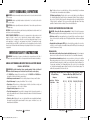
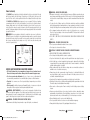
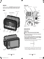
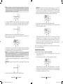
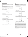
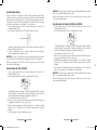
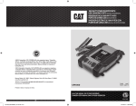
14982045
14982052
14982060
DOCKSIDE BATTERY CHARGER | MODEL 14982045
15Amp with Engine Start Timer
DOCKSIDE BATTERY CHARGER | MODELS 14982052, 14982060
30Amp and 40Amp with Engine Start
Owner’s Manual
BC15_30_40BWM_ManualEN_120513.indd 1
12/5/2013 3:53:05 PM
SAFETY GUIDELINES / DEFINITIONS
HAZARD: Indicates an imminently hazardous situation which, if not avoided, will result in death
or serious injury.
WARNING: Indicates a potentially hazardous situation which, if not avoided, could result in
death or serious injury.
CAUTION: Indicates a potentially hazardous situation which, if not avoided, may result in minor
or moderate injury.
CAUTION: Used without the safety alert symbol indicates potentially hazardous situation which, if not
avoided, may result in property damage.
RISK OF UNSAFE OPERATION. When using tools or equipment, basic safety precautions should
always be followed to reduce the risk of personal injury. Improper operation, maintenance or
modification of tools or equipment could result in serious injury and property damage. There are
certain applications for which tools and equipment are designed. The manufacturer strongly
recommends that this product NOT be modified and/or used for any application other than for which
it was designed. Read and understand all warnings and operating instructions before using any tool
or equipment.
IMPORTANT SAFETY INSTRUCTIONS
WARNING: This product or its power cord contains lead, a chemical known to the State of
California to cause cancer and birth defect or other reproductive harm. Wash hands after handling.
GENERAL SAFETY WARNINGS AND INSTRUCTIONS FOR ALL BATTERY CHARGERS
READ ALL INSTRUCTIONS
WARNING: Read all instructions before operating product. Failure to follow all
instructions listed below may result in electric shock, fire and/or serious injury.
• The 14982045 was designed for household use only. The 14982052 and 14982060 were
designed for both household and commercial use.
• Avoid dangerous environments. Don’t use battery chargers in damp or wet locations.
• Keep children away. Keep away from children. This is not a toy!
• Store indoors. When not in use, battery chargers should be stored indoors in dry, and
high or locked-up places – out of reach of children.
• Unplug the battery charger when not in use.
• Check for damaged parts. Any part that is damaged should be properly repaired or
replaced by manufacturer unless otherwise indicated elsewhere in this instruction manual
before further use.
• First aid – skin: if battery acid comes in contact with skin, rinse immediately with water,
then wash thoroughly with soap and water. If redness, pain, or irritation occurs, seek
immediate medical attention.
Battery Chargers
BC15_30_40BWM_ManualEN_120513.indd 2-3
2
1-877-571-2391
Eyes: If battery acid comes in contact with eyes, flush eyes immediately, for a minimum
of 15 minutes and seek immediate medical attention.
LCD liquid crystal display: If liquid crystal comes in contact with your skin: Wash area
off completely with plenty of water. Remove contaminated clothing. If liquid crystal gets
into your eye: Flush the affected eye with clean water and then seek medical attention.
If liquid crystal is swallowed: Flush your mouth thoroughly with water. Drink large
quantities of water and induce vomiting. Then seek medical attention.
SPECIFIC SAFETY INSTRUCTIONS FOR POWER CORDS
HAZARD – Never alter AC cord or plug provided: if it will not fit the outlet, have aproper
outlet installed by a qualified electrician. Improper connection can result in a risk of an electric shock.
• Don’t abuse cord. Never carry appliance by cord or yank it to disconnect from receptacle.
Keep cord from heat, oil, and sharp edges. Pull by plug rather than cord when unplugging
the unit.
• Ground fault circuit interrupter (GFCI) protection should be provided on the circuits or
outlets to be used. Receptacles are available having built in GFCI protection and may be
used for this measure of safety.
Extension Cords
• An extension cord should not be used unless absolutely necessary. Use of an improper
extension cord could result in a risk of fire and electric shock, and will void warranty.
• If an extension cord must be used, make sure your extension cord is in good condition.
When using an extension cord, be sure to use one heavy enough to carry the current your
product will draw. An undersized cord will cause a drop in line voltage resulting in loss
of power and overheating. The following table shows the correct size to use depending
on cord length and nameplate ampere rating. If in doubt, use the next heavier gauge. The
smaller the gauge number, the heavier the cord.
Recommended Minimum AWG Size for Extension Cords for Battery Chargers
AC Input Rating
American Wire Gage (AWG) Size of Cord
Amperes
Length of Cord, feet (m)
Equal to or But less
greater than
than
0
2
2
3
3
4
4
5
5
6
6
8
8
10
10
12
12
14
14
16
16
18
18
20
25 (7.6)
18
18
18
18
18
18
18
16
16
16
14
14
Battery Chargers
50 (15.2) 100 (30.5) 150 (45.6)
18
18
18
18
16
16
14
14
12
12
12
12
3
18
16
16
14
14
12
12
10
10
10
8
8
16
14
14
12
12
10
10
8
8
8
8
6
1-877-571-2391
12/5/2013 3:53:05 PM
Power Cord Safety
The 14982045 has a polarized plug (one blade is wider than the other) as a safety feature. This plug
will fit into a polarized outlet only one way. If the plug does not fit fully into the outlet, reverse the
plug. If it still does not fit, contact a qualified electrician. Do not attempt to defeat this safety feature.
The 14982052 and 14982060 battery chargers are for use on a nominal 120-volt circuit, and have
a grounding plug that looks like the plug illustrated in the sketch A in the illustration below. A
temporary adapter, which looks like the adapter illustrated in sketches B and C, may be used to
connect this plug to a two-pole receptacle as shown in sketch B if a properly grounded outlet is not
available. The temporary adapter should be used only until a properly grounded outlet can be installed
by a qualified electrician.
HAZARD: Before using adapter as illustrated, be certain that center screw of outlet plate is
grounded. The green-colored rigid ear or lug extending from adapter must be connected to a properly
grounded outlet– make certain it is grounded. If necessary, replace original outlet cover plate screw
with a longer screw that will secure adapter ear or lug to outlet cover plate and make ground
connection to grounded outlet.
•
•
•
•
WARNING – TO REDUCE THE RISK OF FIRE:
• Do not operate near flammable materials, fumes or gases.
• Do not expose to extreme heat or flames.
•
•
•
•
SPECIFIC SAFETY INSTRUCTIONS FOR BATTERY CHARGERS
•
• UL Safety Standards do not recommend any chargers be used onboard vessels.
Never use in damp or wet locations. Always refer to the manual for proper usage.
• Use of accessories and attachments: the use of any accessory or attachment not
recommended by manufacturer for use with this battery charger could be hazardous.
• Stay alert. Use common sense. Do not operate battery charger when you are tired or
impaired.
• Do not operate the battery charger near flammable liquids or in gaseous or explosive
atmospheres. Motors may spark, and the sparks might ignite fumes.
•
WARNING – BURST HAZARD: Do not use the unit for charging dry-cell batteries that are
commonly used with home appliances. These batteries may burst and cause injury to persons and
damage property. Use the unit for charging/boosting a 12 volt battery only. It is not intended to supply
power to a low-voltage electrical system other than in a starter-motor application.
•
WARNING – TO REDUCE THE RISK OF ELECTRIC SHOCK:
• Never immerse the battery charger in water or any other liquid, or use when wet.
Battery Chargers
BC15_30_40BWM_ManualEN_120513.indd 4-5
4
1-877-571-2391
WARNING – RISK OF EXPLOSIVE GASES:
Working in the vicinity of a lead acid battery is dangerous. Batteries generate explosive
gases during normal battery operation. For this reason, it is of the utmost importance that
each time before using the battery charger you read this manual and follow instructions
exactly.
To reduce the risk of battery explosion, follow these instructions and those published
by the battery manufacturer and manufacturer of any equipment you intend to use in the
vicinity of the battery. Review cautionary markings on these products and on the engine.
This equipment employs parts (switches, relays, etc.) that produce arcs or sparks.
Therefore, if used in a garage or enclosed area, the unit MUST be placed not less than 18
inches above the floor.
THIS UNIT IS NOT FOR USE BY CHILDREN AND SHOULD ONLY BE OPERATED BY
ADULTS.
•
•
•
•
•
•
CAUTION – TO REDUCE THE RISK OF INJURY OR PROPERTY DAMAGE:
NEVER ATTEMPT TO CHARGE A FROZEN BATTERY.
Do not charge the battery while the engine is operating.
Stay clear of fan blades, belts, pulleys, and other parts that can cause injury to persons.
Vehicles that have on-board computerized systems may be damaged if vehicle battery
is jump-started. Before jump-starting, read the vehicle’s owner’s manual to confirm that
external-starting assistance is suitable.
When working with lead acid batteries, always make sure immediate assistance is
available in case of accident or emergency.
Always have protective eyewear when using this product: contact with battery acid
may cause blindness and/or severe burns. Be aware of first aid procedures in case of
accidental contact with battery acid.
Have plenty of fresh water and soap nearby in case battery acid contacts skin.
If battery acid contacts skin or clothing, wash immediately with soap and water for at least
10 minutes and get medical attention immediately.
Never smoke or allow a spark or flame in vicinity of vehicle battery, engine or battery
charger.
Remove personal metal items such as rings, bracelets, necklaces and watches when
working with a lead acid battery. A lead acid battery can produce a short circuit current
high enough to weld a ring, or similar metal object, to skin causing a severe burn.
Never allow battery acid to come in contact with this unit.
Do not operate this unit in a closed area or restrict ventilation in any way.
Always turn the battery charger off by unplugging it when not in use.
Battery Chargers
5
1-877-571-2391
12/5/2013 3:53:06 PM
• Do not open the BATTERY CHARGER — there are no user-serviceable parts inside.
Opening the battery charger will void manufacturer’s warranty.
• Operate battery charger only as described in this Instruction Manual.
• Check battery charger and components periodically for wear and tear. Return to
manufacturer for replacement of worn or defective parts immediately.
PREPARING TO CHARGE
1. Be sure area around battery is well ventilated while battery is being charged.
2. Remove battery completely from boat/airplane or any confined area before charging.
3. If it is necessary to remove battery from vehicle to charge, or to clean terminals, always remove
grounded terminal from battery first. Make sure all accessories in the vehicle are off, so as not
to cause an arc.
4. Clean battery terminals, taking care to avoid getting corrosive material in eyes.
5. Add distilled water in each cell until battery acid reaches level specified by battery manufacturer.
This helps purge excessive gas from cells. Do not overfill. For a battery without cell caps
(maintenance free), carefully follow manufacturer’s charging instructions.
6. Study all battery manufacturer’s specific precautions, such as removing or not removing cell caps
while charging, and recommended rates of charge.
7. Determine voltage of battery to be charged by referring to the vehicle manual. The unit is for
charging a 12 volt battery only.
Charger Location
• Locate charger as far away from battery as cables permit.
• Never place charger directly above battery being charged; gases from battery will corrode
and damage charger.
• Never allow battery acid to drip on charger when reading gravity or filling battery.
• Never operate charger in a closed-in area or restrict ventilation in any way.
• Marine batteries must be removed and charged on shore.
• Do not set a battery on top of charger.
Connection Precautions
• Connect and disconnect output clamps only after removing AC cord from electric outlet.
• Never allow clamps to touch each other.
• Attach clamps to battery and chassis as indicated in “Battery Installed in Vehicle” steps 5
and 6, or in “Battery Outside of Vehicle” steps 2 to 5.
Follow these steps when the battery is installed in a vehicle
WARNING – A spark near the battery may cause an explosion. To reduce risk of a
spark near the battery:
1. Position AC and clamp cords to reduce risk of damage by hood, door, or moving engine part.
2. Stay clear of fan blades, belts, pulleys, and other parts that can cause injury to persons.
Battery Chargers
BC15_30_40BWM_ManualEN_120513.indd 6-7
6
1-877-571-2391
3. Check polarity of battery posts. POSITIVE (POS, P, +) battery post usually has larger diameter
than NEGATIVE (NEG, N, –) post.
4. Determine which post of battery is grounded (connected) to the chassis. If negative post is
grounded to chassis (as in most vehicles), see 5. If positive post is grounded to the chassis,
see 6.
5. For negative-grounded vehicle, connect POSITIVE (RED) clamp from battery charger to POSITIVE
(POS, P, +) ungrounded post of battery. Connect NEGATIVE (BLACK) clamp to vehicle chassis or
engine block away from battery. Do not connect clip to carburetor, fuel lines, or sheet-metal body
parts. Connect to heavy gauge metal part of the frame or engine block.
6. For positive-grounded vehicle, connect NEGATIVE (BLACK) clamp from battery charger to
NEGATIVE (NEG, N, –) ungrounded post of battery. Connect POSITIVE (RED) clamp to vehicle
chassis or engine block away from battery. Do not connect clip to carburetor, fuel lines or sheetmetal body parts. Connect to a heavy gauge metal part of the frame or engine block.
7. When disconnecting charger, disconnect AC cord, remove clamp from vehicle chassis, and then
remove clamp from battery terminal.
8. Do not charge the battery while the engine is operating.
9. See operating instructions for length of charge information.
Follow these steps when the battery has been removed from a vehicle
WARNING – A spark near the battery may cause an explosion. To reduce risk of a
spark near the battery:
1. Check polarity of battery posts. The Positive post (marked POS,P, +) usually has a larger
diameter than the Negative battery post (marked NEG, N, –).
2. Attach a 24-inch (minimum length) AWG #6 insulated battery cable to the Negative battery post
(marked NEG, N, –).
3. Connect the Positive (RED) battery clamp to the Positive battery post (marked POS, P, + or red).
4. Stand as far back from the battery as possible, and do not face battery when making final
connection.
5. Carefully connect the NEGATIVE (BLACK) charger clamp to the free end of the battery cable
connected to the negative terminal.
6. When disconnecting charger, always do so in reverse sequence of connecting procedure and
break first connection while as far away from battery as practical.
Note: A marine (boat) battery must be removed and charged on shore. To charge it on board requires
equipment specifically designed for marine use. This unit is NOT designed for such use.
• Check unit periodically for wear and tear. Return to manufacturer for replacement of worn
or defective parts immediately.
• Read and Understand This Instruction Manual Before Using This Unit.
SAVE THESE INSTRUCTIONS
WARNING – TO REDUCE THE RISK OF INJURY:
Follow these instructions and those published by the battery manufacturer and manufacturer of any
equipment you intend to use with this unit. Review cautionary markings on this product and on
engine.
Battery Chargers
7
1-877-571-2391
12/5/2013 3:53:06 PM
INTRODUCTION
LCD Display Detail
Marine®
Congratulations on purchasing your West
battery charger. Read this Instruction
Manual and follow the instructions carefully before using your new battery charger.
FEATURES
ALTERNATOR CHECK BUTTON
DIGITAL DISPLAY (VARIES
BY FUNCTION)
AMPERES/ VOLTAGE/ SECONDS
INDICATOR
BATTERY RECONDITION INDICATOR
BATTERY
CHARGE
GAGE
CLAMP
ICONS
14982045: ENGINE START TIMER BUTTON
14982052/14982060: ENGINE START BUTTON
POSITIVE (RED) CLAMP
FAULT ICON
BATTERY
RECONDITIONING
ICONS
ARROW ICONS
BATTERY ICON
ALTERNATOR
ICON
LOW SURROUNDING
TEMPERATURE ICON
OVERHEAT ALARM
ICON
ENGINE START ICON
HIGH SURROUNDING
TEMPERATURE ICON
OPERATING INSTRUCTIONS
BACKLIT BATTERY
CHARGE BUTTON
LCD SCREEN
BATTERY VOLTAGE
CHECK BUTTON
120 VOLT AC STORAGE
COMPARTMENT
BATTERY RECONDITION
BUTTON
120 VOLT AC PLUG (TWO PRONGS FOR 14982045;
THREE PRONGS FOR 14982052 AND 14982060)
Battery Chargers
BC15_30_40BWM_ManualEN_120513.indd 8-9
8
1-877-571-2391
NEGATIVE (BLACK)
CLAMP
Charging the Battery
WARNING – TO REDUCE THE RISK OF INJURY OR PROPERTY DAMAGE:
• Always disconnect the AC plug from the AC outlet first before disconnecting the
charger from the battery to be charged.
• Ensure that all installation, operating instructions and safety precautions are
understood and always carefully followed by the steps outlined in the “IMPORTANT
SAFETY INSTRUCTION” section at the front of this manual.
1. Plug the battery charger’s power cord into an AC outlet. The LCD screen will display the
following (the clamp icon will flash and the empty battery icon will light):
2. The charger’s battery clamps are color-coded. Red is positive; black is negative. Connect the
battery clamps correctly to the corresponding connectors on the battery posts following the
steps outlined in the “IMPORTANT SAFETY INSTRUCTION” section at the front of this manual.
Battery Chargers
9
1-877-571-2391
12/5/2013 3:53:06 PM
Notes: If the clamps are correctly connected with regard to polarity and the unit is properly
connected to the AC outlet, the unit will be in Standby mode and the LCD screen will display the
following (the clamp icons, arrow icons and the battery icon light solid) and the battery charge
gauge will indicate the battery’s current charge status)
If the clamps are INCORRECTLY connected with regard to polarity, the LCD screen will display
the following (the “+” and “–” inside the battery icon, the clamp icons and the fault icon will flash
and the battery icon will light) and a warning will sound until the clamps are disconnected:
Unplug the charger; then remove the clamps. Reconnect the clamps properly.
3. When the unit is properly connected, press the battery charge button on the control panel. The
LCD screen will display the following:
The digital display shows the output current that is charging the battery. The gauge indicates
the charge status of the battery. The clamp icons and the battery icon light solid, and the arrow
icons will gradually and repeatedly move downward to the battery icon.
Notes: The “ ” icon will appear at the top right of the gauge section if the surrounding ambient
temperature is higher than approximate 40°C. The “ ” icon will appear at the top left of the
gauge section if the surrounding ambient temperature is lower than 0°C. This is not a fault code,
but indicates that the unit’s temperature compensation feature is operating.
The charging process will start automatically approximately one minute after the unit is properly
connected.
IMPORTANT: If the battery is overheated, the LCD screen will display the following flashing
icons:
IMPORTANT: If the battery is not fully charged (the battery charge gauge does not reach 100%)
after 18 hours of continuous charging, the battery may have internal damage and will not accept
a charge. After 18 hours, the charging process will automatically cut-off, the LCD screen will
display the following (the digital readout shows “F04”, the battery charge gauge will indicate the
battery’s current charge status, and the clamp icons and battery icon will light solid.):
Disconnect the charger. Have the battery checked by a qualified technician.
4. When the battery is completely charged, the unit automatically goes into float charge mode and
the LCD screen displays the following:
The digital display shows “FLO” to indicate that the unit is in float charge mode. The battery
charge gauge points to 100%, indicating a full charge. The clamp icon and battery icon light
solid, and the arrow icons will gradually and repeatedly move downward to the battery icon.
In this mode, the unit monitors the battery voltage and charges as necessary to assure the
battery maintains full capacity. The unit remains in float charge mode as long as the charger is
connected to the battery and plugged into a functioning AC outlet.
When disconnecting charger, disconnect the AC cord, remove clamp from vehicle chassis, and then
remove clamp from battery terminal.
Checking the Battery Voltage
TO CHECK THE BATTERY VOLTAGE IN STANDBY OR CHARGING MODE
1. Set up the battery charger and connect to the battery following steps 1 through 2 in the
“Charging the Battery” section.
2. Press the battery voltage check button. The LCD screen will display the following:
The digital display shows the current voltage of the connected battery for 10 seconds. During
this period, pressing the battery voltage check button again will return the unit to standby mode
or charging mode. Pressing any other buttons will have no effect. The unit will automatically
return to standby or charging mode after 10 seconds.
Disconnect the charger. Have the battery checked by a qualified technician.
Battery Chargers 10 1-877-571-2391
BC15_30_40BWM_ManualEN_120513.indd 10-11
Battery Chargers 11 1-877-571-2391
12/5/2013 3:53:06 PM
Using the Alternator Check Function
PART 2
Set up the battery charger and connect to the battery following steps 1 through 2 in the “Charging the
Battery” section.
Under Load (accessories ON): Next, load the alternator by turning on as many accessories as
possible (except for A/C and Defrost).
1. Press the alternator check button to start the check. The LCD screen will display the following to
indicate the unit is analyzing the alternator:
PART 1
No Load (turn OFF all vehicle’s accessories): The battery must be fully charged before testing
the alternator. Run the engine long enough to achieve normal idle speed and verify there is a no-load
voltage.
1. Press the alternator check button to start the check. The LCD screen will display the following to
indicate the unit is analyzing the alternator:
The alternator icon will flash.
2. If the unit detects that the alternator is good, the LCD screen will display the following:
The alternator icon will flash.
2. If the unit detects that the alternator is good, the LCD screen will display the following:
The alternator icon and “ALT GOOD” will light solid.
3. If the unit detects that the alternator is out of typical voltage range, the LCD screen will display
the following:
The alternator icon and “ALT GOOD” will light solid.
3. If the unit detects that the alternator is out of typical voltage range, the LCD screen will display
the following:
The fault icon will flash. The alternator icon and “CHECK ALT” will light solid.
4. Press the alternator check button again to stop the test.
Notes:
The fault icon will flash. The alternator icon and “CHECK ALT” will light solid.
4. Press the alternator check button again to stop the test.
All buttons except the alternator check button are disabled in alternator check mode.
The unit may detect that the alternator is out of typical voltage range because someone has added a
number of accessory loads on the charging system, thereby increasing current demand from the
alternator. MAKE SURE THAT THE ALTERNATOR IS RATED TO SUPPORT THE APPLICATION.
This check may not be accurate for every make, manufacturer and model of vehicle. Check only 12
volt systems.
When disconnecting the charger, disconnect AC cord, remove clamp from vehicle chassis, and then
remove clamp from battery terminal.
Battery Chargers 12 1-877-571-2391
BC15_30_40BWM_ManualEN_120513.indd 12-13
Battery Chargers 13 1-877-571-2391
12/5/2013 3:53:06 PM
Reconditioning the Battery
Periodic reconditioning is recommended to maintain a battery’s optimum performance. Battery
recondition sends a series of electrical pulses to break up the crystalline form of lead sulfate and turn
these chemicals into useful battery electrolytes. The process will stop automatically after 24 hours. To
stop the process sooner, press the battery recondition button a second time. More than 24 hours may
be needed to restore performance on some batteries. If so, repeat the process.
1. Set up the battery charger and connect to the battery following steps 1 through 2 in the
“Charging the Battery” section.
2. Press the battery recondition button. The LCD screen will display the following:
The battery recondition indicator, the clamp icons and the battery icon will light solid; and the
battery reconditioning icons will flash.
3. To stop the reconditioning process, press the battery recondition button again. Pressing any
other button during this process will have no effect.
IMPORTANT: If 5 cycles of reconditioning does not improve battery performance, discontinue and
recycle the battery. The battery charger will go into charging mode after 24 hours automatically.
When disconnecting charger, disconnect AC cord, remove clamp from vehicle chassis, and then
remove clamp from battery terminal.
Using the Engine Start Timer (14982045)
1. Set up the battery charger and connect to the battery following steps 1 through 2 in the
“Charging the Battery” section.
2. Press the engine start timer button. The LCD screen will display the following:
IMPORTANT: The function requires a resting/cooling period between attempts. Wait 4 to 5 minutes
before a second attempt at starting the engine, if needed.
When disconnecting charger, disconnect AC cord, remove clamp from vehicle chassis, and then
remove clamp from battery terminal.
Using the Engine Start Function (14982052 and 14982060)
1. Set up the battery charger and connect to the battery following steps 1 through 2 in the
“Charging the Battery” section.
2. Press the engine start button. The LCD screen will display the following*:
The digital display shows the countdown.* The battery charge gauge will indicate the battery’s
current charge status. The engine start icon, clamp icons and battery icon light solid, and the
arrow icons will gradually and repeatedly move downward to the battery icon.
*The countdown will commence from “90” to “00”.
3. When “00” is reached, a beep will sound, the battery icon will light solid and the engine start
icon ( ) will begin flashing. The vehicle is ready to start.
4. Crank the engine using manufacturer’s guidelines, typically in 3 to 5 second bursts. The digital
display shows “5 sec.” indicating a 5-second countdown, the gauge and all other indicators
disappear.
5. After cranking, the unit will automatically adjust the charging current to 2A for 5 minutes and
then revert to charging mode. To stop charging, press the charge button.
IMPORTANT: The function requires a resting/cooling period between attempts. Wait 4 to 5 minutes
before a second attempt at starting the engine, if needed.
When disconnecting charger, disconnect AC cord, remove clamp from vehicle chassis, and then
remove clamp from battery terminal.
The digital display shows the countdown.* The battery charge gauge will indicate the battery’s
current charge status. The engine start icon, clamp icons and battery icon light solid, and the
arrow icons will gradually and repeatedly move downward to the battery icon.
*The countdown will commence from “480” to “00”.
3. When “00” is reached, a beep will sound, the battery icon will light solid and the engine start
icon ( ) will begin flashing. The vehicle is ready to start.
4. Crank the engine using manufacturer’s guidelines, typically in 3 to 5 second bursts. The digital
display shows “5 sec.” indicating a 5-second countdown, the gauge and all other indicators
disappear.
5. To stop charging, press the engine start timer button again.
Battery Chargers 14 1-877-571-2391
BC15_30_40BWM_ManualEN_120513.indd 14-15
Battery Chargers 15 1-877-571-2391
12/5/2013 3:53:06 PM
CARE AND MAINTENANCE
Storage
• Store the unit in a clean, dry, cool place when not in use.
• Clean the unit casing and cords (as necessary) with a dry (or slightly damp) cloth. Ensure
that unit is completely disconnected from battery and power source before cleaning.
• To maintain the operating condition and maximize the life of the charger cords, always
coil them loosely for storage. Do not wrap them around the unit or crimp them with a
tight band.
ACCESSORIES
Recommended accessories for use with this unit may be available from the manufacturer. If you need
assistance regarding accessories, please contact Customer Service at 1-877-571-2391.
WARNING: The use of any accessory not recommended for use with this appliance could be
hazardous.
SERVICE INFORMATION
Whether you need technical advice, repair, or genuine factory replacement parts, contact Customer
Service at 1-877-571-2391.
LIMITED ONE-YEAR WARRANTY
What to do?
1. Before you call for service, check the troubleshooting guide in your owner’s manual. A slight
adjustment of any custom controls may save you a service call.
2. If you require service during the warranty period, you must carefully pack the product (preferably
in the original package) and ship it by prepaid transportation with a copy of the original receipt
from the retailer to an authorized service center.
3. Please describe your problem in writing and include your name, a return UPS shipping address
(P.O. Box not acceptable), and a daytime phone number with your shipment.
4. For more information and for the location of the nearest authorized service center please contact
us by one of the following methods:
• Call us toll-free at 1-877-571-2391
• E-mail us at [email protected]
Exclusion of Certain Damages: This warranty is exclusive and in lieu of any and all other
warranties, expressed or implied, including without limitation the implied warranties of merchantability
and fitness for a particular purpose and any obligation, liability, right, claim or remedy in contract or
tort, whether or not arising from the company’s negligence, actual or imputed. No person or
representative is authorized to assume for the company any other liability in connection with the sale
of this product. In no event shall the company be liable for indirect, incidental or consequential
damages.
TROUBLESHOOTING
Problem
This warranty gives you specific legal rights. You may also have other rights which vary from state
to state.
West Marine warrants this product to the original purchaser to be free from defects in material and
workmanship for a period of one year from the date of the original purchase.
West Marine agrees, at our option, during the warranty period, to repair any defect in material or
workmanship or to furnish an equal new, renewed or comparable product (whichever is deemed
necessary) in exchange without charges, subject to verification of the defect or malfunction and proof
of the date of purchase. Subsequent replacement products are warranted for the balance of the original
warranty period.
Cause
Loose connections
Unit not charging
No power to unit
Battery will not accept a charge
Action
Make sure all connections are secure
Check that the charger is properly
connected to a live 120 volt AC outlet
If the battery to be charged has fallen
below 2 volts, it cannot be charged
with these chargers
Who is covered? This warranty is extended to the original retail purchaser for products purchased
from an authorized West Marine dealer and used in the U.S.A.
What is covered? This warranty covers all defects in material and workmanship in this product. The
following are not covered: software, installation/removal costs, damage resulting from accident,
misuse, abuse, neglect, product modification, improper installation, incorrect line voltage,
unauthorized repair or failure to follow instructions supplied with the product, or damage occurring
during return shipment of the product. Specific license conditions and copyright notices for the
software can be found via www.baccusglobal.com
Battery Chargers 16 1-877-571-2391
BC15_30_40BWM_ManualEN_120513.indd 16-17
Battery Chargers 17 1-877-571-2391
12/5/2013 3:53:07 PM
SPECIFICATIONS
FCC COMPLIANCE
14982045
This device complies with Part 15 of the FCC Rules. Operation is subject to the following two
conditions:
Input 120VAC, 60Hz, 270W
Output 12VDC, 15A
Engine start timer
14982052
Input 120VAC, 60Hz, 520W
Output 12VDC, 30A
80A engine start
(ON: 5 seconds, OFF:
5 minutes)
14982060
Input 120VAC, 60Hz, 9.5A
1500W engine start
Output 12VDC, 40A
110A engine start
(ON: 5 seconds, OFF:
5 minutes)
(1) this device may not cause harmful interference, and
(2) this device must accept any interference received, including interference that may cause undesired
operation.
Warning: Changes or modifications to this unit not expressly approved by the party responsible for
compliance could void the user’s authority to operate the equipment.
Note: This equipment has been tested and found to comply with the limits for a Class B digital
device, pursuant to Part 15 of the FCC Rules. These limits are designed to provide reasonable
protection against harmful interference in a residential installation. This equipment generates, uses
and can radiate radio frequency energy and, if not installed and used in accordance with the
instructions, may cause harmful interference to radio communications. However, there is no guarantee
that interference will not occur in a particular installation. If this equipment does cause harmful
interference to radio or television reception, which can be determined by turning the equipment off
and on, the user is encouraged to try to correct the interference by one or more of the following
measures:
• Reorient or relocate the receiving antenna.
• Increase the separation between the equipment and receiver.
• Connect the equipment into an outlet on a circuit different from that to which the receiver
is connected.
• Consult the dealer or an experienced radio/TV technician for help.
Battery Chargers 18 1-877-571-2391
BC15_30_40BWM_ManualEN_120513.indd 18-19
Battery Chargers 19 1-877-571-2391
12/5/2013 3:53:07 PM
Toll Free: 1-877-571-2391
www.westmarine.com,
©2013 West Marine. All rights reserved.
WM_Version 1_DEC 2013
BC15_30_40BWM_ManualEN_120513.indd 20
12/5/2013 3:53:07 PM