1
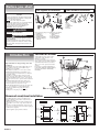
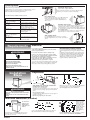
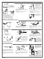
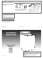
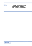
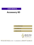
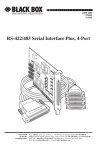
Completing installation
CHECK ELECTRICAL REQUIREMENTS. BE SURE YOU HAVE
CORRECT ELECTRICAL SUPPLY AND RECOMMENDED
EARTHING METHOD.
Check that all parts are now installed. If there is an extra part, go
back through steps to see which step was skipped.
Turn on water faucets and check for leaks. Tighten couplings if there
is leaking. DO NOT OVERTIGHTEN; this could cause damage to
couplings.
Check that you have all of your tools. Check that the shipping
strap was removed from the back of the washer and used to
secure the drain hose.
Untape and plug power supply cord into earthed outlet.
Read the Use and Care Guide. Start the washer and allow it to
complete the regular cycle.
Congratulations!
You have successfully installed your new Whirlpool washer. To
get the most efficient use from your new washer, read your Use
and Care Guide.
Keep Installation Instructions and Use and Care Guide.
Need assistance?
Call your dealer or local authorized service company.
When you call, you will need the washer model number and serial
number. Both numbers are on the model/serial rating plate located
under the washer lid and on the top of the washer.
Part No. 8318424 Rev. A
©2000 Whirlpool Corporation
Benton Harbor, Michigan 49022
Printed in U.S.A.
Installation
Instructions
230-volt, 50-Hz
Washer
for models
3RLBR8543
3RLSQ8000
3RGSC9455
3SLSQ7533
3RLSQ8533
IMPORTANT:
Read and save these instructions.
Part No. 8318424 Rev. A
Installer: Leave Installation Instructions with the homeowner
Homeowner: Keep Installation Instructions for future reference.
Save Installation Instructions for local electrical inspector’s use.
Before you start
Parts supplied for installation
Your safety and the safety of others are very
important.
We have provided many important safety messages
in this manual and on your appliance. Always read
and obey all safety messages.
This is the safety alert symbol.
This symbol alerts you to potential hazards
that can kill or hurt you and others.
All safety messages will follow the safety alert
symbol and either the word “DANGER” or
“WARNING”. These words mean:
Tools needed for installation
D
C
D
A
F
G
A
E
H
DANGER
You can be killed or seriously injured if you don’t
immediately follow instructions.
WARNING
You can be killed or seriously injured if you don’t
follow instructions.
All safety messages will tell you what the potential
hazard is, tell you how to reduce the chance of injury,
and tell you what can happen if the instructions are
not followed.
Introduction
Important: Observe all governing codes and
ordinances.
Check location where washer will be installed. Make sure you
have everything necessary for correct installation. Proper
installation is your responsibility.
Water heater: Set to deliver 60°C (140°F) water to washer.
Earthed electrical outlet (A) is required within 152 cm
(5 feet) of upper left corner of washer cabinet. See “Electrical
requirements”, Panel B.
The installer is to confirm, through the local power supply
authority, if necessary, that the machine is connected to a power
supply with a maximum impedance of 0.068 + j0.043 ohms for
phases (RA + jXA) and 0.0455 + j0.02844 ohms for neutral (RN
+ jXN).
Hot and cold water faucets (B): Must be within 122 cm
(4 feet) of the upper right corner of the washer cabinet and
provide water pressure 34.5-689.6 kPa (5-100 psi).
B
A. level
B. wrench
C. utility knife
D. pliers
E. scissors
B
I
E
C
Remove parts from packages. Check that all parts were included.
A. 1 drain hose
B. 2 inlet hoses
C. 1 yellow clamp
D. 2 drain hose clamps
E. 2 front leveling legs
with nuts
F. 6 flat water hose
washers
G. 1 hose extension
H. literature package
I. faucet adapters
Location of washer
Support (D): Floor must be sturdy enough to
support washer weight (with water) of 143
kilograms (315 pounds).
The minimum and maximum motor rotation per
minute (R.P.M.) is 950-1425 R.P.M. The minimum
and maximum basket R.P.M. is 423-640 R.P.M.
Allow 2.5 cm (1 inch) of space between washer
and dryer.
Do Not store or operate washer below 0°C
(32°F) (some water may remain in washer).
See Use & Care Guide for “Winterizing”
information.
The hot and cold water inlets on the back of the washer have
3/4 — 11-1/2 American hose coupling standard threads.
Level floor (C): Maximum slope under entire washer —
2.5 cm (1 inch).
Installing washer on carpeting is not recommended.
A
B
D
C
Recessed area/closet installation
The installation dimensions shown are the minimum spaces
allowable. Additional spacing should be considered for ease of
installation and servicing.
Additional clearances for wall, door and floor moldings may be
required. Allow 2.5 cm (1 inch) of space between washer and
dryer.
If closet door is installed, the minimum air openings in top and
bottom of door are required. Louvered doors with air openings in
top and bottom are acceptable.
Companion appliance spacing should be considered.
Front view
Front view (door not shown)
Side view
closet door
closet door
7,6 cm (3")
35,6 cm
máx.
(14" max.)
310 cm2
(48 inches2)
310 cm2
(48 inches2)
43,2 cm (17")
155 cm2
(24 inches2)
7,6 cm (3")
Panel A
10,2 cm
mín.
(4" min.)
155 cm2
(24 inches2)
0 cm
(0")
0 cm
(0")
2,5 cm mín.
(1" min.)
Drain system
Untape and open washer lid. Remove packages and hoses from washer. Follow
directions for your type of drain system.
If a longer drain hose is needed, use drain hose extension kit (Part No. 285702).
If drain hose must be shortened, use drain hose kit (Part No. 285442).
Laundry tub drain system:
Needs a 76-liter (20-gallon) laundry tub.
Top of tub must be at least 86 cm (34 inches) high and no higher
than 183 cm (72 inches) from bottom of washer (A).
A
All kits are available from authorized parts distributors.
Select the drain hose installation method you need.
If your home has:
99 cm (39") to 183 cm (72’’) high,
5,1 cm (2") dia. standpipe
2,5 cm (1")
standpipe
floor drain
overhead sewer
standard 76 liters (20 gal.),
86 cm (34") high drain tub or
utility sink
water not close by
Floor drain system:
B
Requires a siphon break, Part No. 285320 (B). Siphon break
must be above high-water level in washer, at least 71 cm
(28 inches) from bottom of washer. Additional drain hose
will be needed.
You will need to buy:
nothing
5,1 cm (2") dia. to 2,5 cm (1") dia.
standpipe adapter, Part No. 3363920
siphon break, Part No. 285320; additional
drain hose, Part No. 3357090;
and Connector Kit, Part No. 285442
standard 76 liters (20 gal.), 86 cm (34")
high drain tub or utility sink and sump
pump (available from local
plumbing suppliers)
nothing
Standpipe drain system:
Needs a 5-cm (2-inch) minimum diameter standpipe with minimum
carry-away capacity of 64 liters (17 gallons) per minute. A 5-cm
(2-inch) diameter to 2.5-cm (1-inch) diameter standpipe adapter, Part
No. 3363920 must be used with 2.5-cm (1-inch) diameter drain system.
Floor standpipe drain:
Top of standpipe (C) must be at least 99 cm (39 inches) high and no
higher than 183 cm (72 inches) from bottom of washer.
C
Wall standpipe drain:
Top of standpipe (D) must be at least 99 cm (39 inches)
high and no higher than 183 cm (72 inches) from bottom of
washer.
2 longer water inlet hoses: 1,8 m (6 ft.)
hoses, Part No. 76313 or 3 m (10 ft.)
hoses, Part No. 350008
Requirements
WARNING
Electrical
Do Not earth to a gas pipe.
Recommended earthing method
Check with a qualified electrician if you are not sure that
washer is properly earthed.
For your personal safety, this washer must be earthed. This
washer is equipped with a power supply cord having an earthing
plug.
To minimize possible shock hazard, the power supply cord must
be plugged into a mating earthing-type wall receptacle earthed in
accordance with local codes and ordinances. If a mating wall
receptacle is not available, it is the personal responsibility and
obligation of the customer to have the proper earthed wall
receptacle installed by a qualified electrician.
Do Not have a fuse in the neutral or earthing circuit.
In the U.S. only: If codes permit and a separate earthing
wire is used, it is recommended that a qualified electrician
determine that the earthing path is adequate.
Electrical Shock Hazard
Plug into an earthed outlet.
Do not remove ground prong.
Do not use an adapter.
Do not use an extension cord.
Failure to do so can result in death, fire, or
electrical shock.
Installation
Steps
If the supply cord of this appliance is damaged, it must be
replaced only by a repair shop appointed by the
manufacturer, because special tools are required.
A 230-volt, 50-Hz, 10-amp, fused electrical supply is required. Timedelay fuse or circuit breaker is recommended. It is recommended
that a separate circuit serving only this appliance be provided.
Preparation
B
A
D
E
C
WARNING
Excessive Weight Hazard
Use two or more people to move and install
washer.
Failure to do so can result in back or other
injury.
D
SLIDE WASHER ONTO CARDBOARD OR HARDBOARD
BEFORE MOVING ACROSS FLOOR.
Pull firmly to remove the other end of the shipping strap (D) from
the back of the washer to release self-leveling legs (E).
Move washer close to its final location.
Read, then remove the label (A) that covers the power supply cord
and drain connector. Peel the tape down and off each side of the
cabinet.
Remove shipping strap (B).
Completely remove the shipping strap with 2 cotter pins (C) from
the inside of the washer.
Pull the strap completely out of the washer.
Save the shipping strap to secure drain hose.
Inlet hose connection (to washer)
Use new hoses,
washers, and
adapters that
came with your
washer.
Check inlet hoses periodically. Replace inlet hoses if you
find bulges, kinks, cuts, wear or leaking. Replace inlet
hoses after five years of use.
Panel B
B
C
A
E
D
Insert one large flat washer (A) into each end of the inlet hoses
(B). Check that washers are firmly seated in couplings (C).
Attach hose (without
adapter) to hot water
(bottom) inlet valve
(D) first; then second
hose (without adapter)
to cold water (top)
inlet valve (E). Tighten
couplings by hand.
Then use pliers to
make additional twothirds turn.
DO NOT OVERTIGHTEN; this could cause damage to couplings.
Inlets are plastic. DO NOT STRIP OR CROSSTHREAD.
Drain hose connection
If drain hose does not fit into
standpipe or is being placed
over the edge of a laundry
tub, open other drain
hose clamp with pliers and place
clamp over rubber end of
drain hose (G).
F
IMPORTANT: THIS
PROCEDURE MUST BE
FOLLOWED TO ASSURE
PROPER INSTALLATION.
G
E
AM
P
CL
C
Standpipe or laundry tub drain system:
Open yellow clamp (E) and slide over “hook” end of drain hose (F)
to secure the rubber and corrugated sections together.
A
B
Floor drain system:
Do Not install “hook” end of drain hose to corrugated section.
Consult your plumber for proper installation.
1/4"
(.64 cm)
Insert end of hose extension (H)
into rubber end of drain hose up
to stops on the sides of hose
extension. Secure with clamp.
H
D
Put “hook” end of drain hose into laundry tub or standpipe. Check
for proper length of drain hose.
To prevent drain water from going back into washer:
• Do Not straighten “hook” end of drain and force excess drain
hose into standpipe.
• Do Not lay excess drain hose in bottom of laundry tub.
Run water through both faucets into
a bucket to get rid of particles in the
water lines that might clog hoses.
Mark the hot water faucet.
To prevent the drain hose from coming off or leaking, it must be
installed per the following instructions.
• Wet the inside end of the drain hose (A) with tap water. DO
NOT USE ANY OTHER LUBRICANT.
• Squeeze ears of one drain hose clamp (B) with pliers to
open and place clamp over the end of the drain hose.
• Open clamp and push end of drain hose onto drain
connector (C) until hose contacts ribbed stop (D).
• Place clamp over area marked “clamp”. Release clamp.
Inlet hose connection (to faucets)
B
A
C
D
F
E
• For both inlet hoses: Insert one large flat washer (A) into end
of coupling (B); then attach faucet adapter (C). Insert one
small washer (D) into end of faucet adapter.
• Make sure washers are firmly seated into couplings.
Attach bottom hose with adapter from the inlet marked “H” to hot
water faucet (E). Attach top hose with adapter from the inlet
marked “C” to cold water faucet (F).
Tighten couplings to faucets by hand; then use pliers to make final
two-thirds turn.
DO NOT OVERTIGHTEN; this could cause damage to couplings.
Leveling washer
B
1.3 cm
(1/2")
C
Screw nut (B) down on legs to within 1.3 cm (1/2 inch) of base (C).
D
Insert legs into correct holes
at each front corner of
washer until nuts touch
washer (D). DO NOT
tighten nuts until washer is
level.
Tilt washer forward, raising back legs 2.5 cm (1 inch) off of floor
to adjust rear self-leveling legs. Drop washer to floor. Check
levelness of the washer by placing a carpenter's level on top of the
washer, first side to side; then front to back.
Tilt washer backward and
remove corner posts. Gently
lower washer to floor.
A
Stack two corner posts (A) on top of each other. Tilt washer
backwards and slide corner posts under washer 7.6 cm
(3 inches) from each side of washer as shown.
If washer is not level, adjust
the front legs (E) up or
down. Repeat above step.
When washer is level,
use wrench to turn nuts
on front legs up tightly
against washer base. If
nuts are not tight against
washer base, the washer
may vibrate.
E
Move washer to its final location. Remove cardboard or
hardboard from under washer.
Securing drain hose
A
E
B
C
about 41 cm
(16")
B
D
D
Note: Use shipping strap to secure drain hose.
Water pressure could cause drain hose to come out
of standpipe or laundry tub if drain hose is not
secured.
Check that hose is not twisted or kinked and is securely in
place.
After shipping strap has been removed from washer, look for
the words “cut here” marked on the shipping strap, about
41 cm (16 inches) from the plug end. Cut the shipping strap
at this mark (A).
Put “hook” end of drain hose in laundry tub (B) or standpipe (C).
Tightly wrap the shipping strap (D) around the drain hose and
laundry tub or standpipe. Push plug into the nearest hole in the
shipping strap.
Panel C
If the water inlet faucets and drain
standpipe are recessed, put “hook”
end of drain hose (E) in standpipe.
Tightly wrap the shipping strap (F)
around the drain hose and faucet
body (not the handle or stem).
Push plug into the nearest hole in
the shipping strap.
F
If a longer drain hose
is needed, drain hose
extension kit (Part No.
285702) is available
from authorized parts
distributors. If drain
hose must be
shortened, use hose
kit (Part No. 285442).
Note: If washer is moved to adjust drain hose, the washer
must be leveled again. Repeat leveling steps, see "Leveling
washer", Panel C. Place cardboard under the washer and
carefully move washer to avoid damaging floor covering.
C
H
Completing installation
CHECK ELECTRICAL REQUIREMENTS. BE SURE YOU HAVE
CORRECT ELECTRICAL SUPPLY AND RECOMMENDED
EARTHING METHOD.
Check that all parts are now installed. If there is an extra part, go
back through steps to see which step was skipped.
Turn on water faucets and check for leaks. Tighten couplings if there
is leaking. DO NOT OVERTIGHTEN; this could cause damage to
couplings.
Check that you have all of your tools. Check that the shipping
strap was removed from the back of the washer and used to
secure the drain hose.
Untape and plug power supply cord into earthed outlet.
Read the Use and Care Guide. Start the washer and allow it to
complete the regular cycle.
Congratulations!
You have successfully installed your new Whirlpool washer. To
get the most efficient use from your new washer, read your Use
and Care Guide.
Keep Installation Instructions and Use and Care Guide.
Need assistance?
Call your dealer or local authorized service company.
When you call, you will need the washer model number and serial
number. Both numbers are on the model/serial rating plate located
under the washer lid and on the top of the washer.
Part No. 8318424 Rev. A
©2000 Whirlpool Corporation
Benton Harbor, Michigan 49022
Printed in U.S.A.
Installation
Instructions
230-volt, 50-Hz
Washer
for models
3RLBR8543
3RLSQ8000
3RGSC9455
3SLSQ7533
3RLSQ8533
IMPORTANT:
Read and save these instructions.
Part No. 8318424 Rev. A
Installer: Leave Installation Instructions with the homeowner
Homeowner: Keep Installation Instructions for future reference.
Save Installation Instructions for local electrical inspector’s use.