1
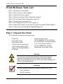
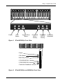
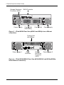
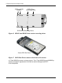
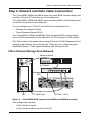
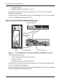
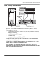
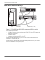
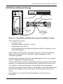
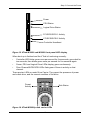
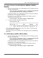
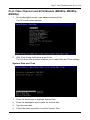
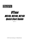
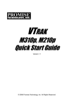
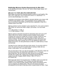
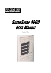
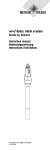
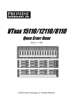
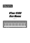
VTRAK
M-Class
M500f, M500i, M500p, M300f, M300i, M300p,
M200f, M200i, M200p
QUICK START GUIDE
Version 1.5 / SR3
© 2006 Promise Technology, Inc. All Rights Reserved.
VTrak M-Class Quick Start Guide
VTrak M-Class Task List
Step 1: Unpack the VTrak (below).
Step 2: Mount VTrak in a Rack (page 5)
Step 3: Install Disk Drives (page 5)
Step 4: Network and Data Cable Connections (page 7)
Step 5: Set Up Serial Cable Connections (page 12)
Step 6: Connect the Power (page 12)
Step 7: Set IP Address with CLI or CLU (page 14)
Step 8: Install iSCSI Initiator on the Host PC (page 24) (M500i, M300i, M200i)
Step 9: VTrak Setup with Embedded WebPAM (page 25)
Step 1: Unpack the VTrak
The VTrak box contains the following items:
•
VTrak Unit
•
Quick Start Guide
•
Null Modem Cable
•
Left and right mounting rails
•
1.0m External VHDCI SCSI
cables (2 for M500p/M300p, 1
for M200p)
•
Screws for disk drives
(36 for M200f/i/p; 52 for M300f/i/p;
64 for M500f/i/p; including 4 spares)
•
1.5m (4.9 ft) Power cords (2)
•
CD with SNMP files, Product
Manual and Quick Start Guide
Warning
The electronic components within the VTrak disk array are
sensitive to damage from Electro-Static Discharge (ESD).
Observe appropriate precautions at all times when handling the
VTrak or its subassemblies.
Important
Use the following categories of network cables with VTrak:
•
Cat 6, preferred
•
Cat 5E, minimum
2
Step 1: Unpack the VTrak
PROMISE
Power
FRU
Status
Logical Drive
Status
FC/iSCSI/
SCSI-1
Activity
FC/iSCSI/
SCSI-2
Activity
Figure 1. VTrak M500f/i/p Front View
Power
FRU Status
Disk Array Status
FC/iSCSI/SCSI-1 Activity
FC/iSCSI/SCSI-2 Activity
Controller Heartbeat
Figure 2. VTrak M300f/i/p and M200f/i/p Front View
3
VTrak M500
Controller
Heartbeat
VTrak M-Class Quick Start Guide
Storage Enclosure
Processor (SEP)
RAID Controller
Controller
Mgmt
FC 1
FC 2
IOIOI
1
Power Supply
2
Cooling Unit
with Battery
Cooling Unit
Power Supply
Figure 3. VTrak M500f Rear View (M500i and M500p have different
controllers)
Cooling Unit
with Battery
Controller
iSCSI 1
iSCSI 2
Mgmt
IOIOI
Power Supply 1
RAID
Controller
Storage
Enclosure
Processor
(SEP)
Power Supply 2
Figure 4. VTrak M300i/M200i Rear View (M300f/M200f and M300p/M200p
have different controllers)
4
Step 2: Mount VTrak in a Rack
Step 2: Mount VTrak in a Rack
The VTrak M-Class subsytems install directly to the rack with or without using the
supplied mounting rails. Refer to Chapter 2 of the VTrak Product Manual on the
CD for instructions on installing the rails and mounting your VTrak.
Step 3: Install Disk Drives
You can populate the VTrak with 1.5 GB or 3.0 GB SATA drives. Refer to Chapter
7 of the VTrak Product Manual on the CD for the number of drives needed for
each RAID configuration.
Install all of the drive carriers into the VTrak enclosure to ensure proper airflow,
even if you do not populate all the carriers with disk drives.
If you use different size disk drives in the same logical drive, the total size of the
logical drive will equal the size of the smallest disk drive times the number of
drives.
Refer to Chapter 2 of the VTrak Product Manual on the CD for diagrams showing
how the drive slots are numbered.
Caution
Use only the counter-sink screws supplied with the VTrak. Use of
other types of screws can damage the adjacent drives.
Counter-sink screws only.
PATA Drive
Mounting Holes
WARNING:
PATA-to-SATA
Adapter
SATA Drive Mounting Holes
Figure 5. M500f/i drive carrier mounting holes
5
VTrak M-Class Quick Start Guide
Counter-sink screws only.
PATA Drive
Mounting Holes
WARNING:
PATA-to-SATA
Adapter
SATA Drive Mounting Holes
Figure 6. M300f/i and M200f/i drive carrier mounting holes
Serial ATA Disk Drive
Figure 7. SATA Disk Drives mount at the front of the carrier
A VTrak M500f/i/p carrier is shown above. The VTrak M300f/i/p and M200f/i/p
carrier is similar in appearance but the two carrier designs are NOT
interchangeable.
6
Step 4: Network and Data Cable Connections
Step 4: Network and Data Cable Connections
The VTrak M500f, M300f and M200f share the same RAID controller design and
use Fibre Channel (FC) connections for the data ports.
The VTrak M500i, M300i and M200i share the same RAID controller design and
use iSCSI connections for the data ports.
You can configure your VTrak FC and iSCSI data connections for a:
•
Storage Area Network (SAN)
•
Direct Attached Storage (DAS)
The VTrak M500p, M300p and M200p share the same RAID controller design
and use SCSI connections for the data ports. SCSI is limited to a DAS solution.
All VTrak models in this series have a single Ethernet (RJ-45) Management Port
connector that enables you to monitor the VTrak over your network using the
WebPAM Software. VTrak supports Ethernet and Telnet protocols.
Fibre Channel Storage Area Network.
Network Switch
FC Switch
Management
Port
Controller
Mgmt
FC 1
FC 2
IOIOI
1
2
VTrak
PC
NIC
FC HBA Card
FC Port (1 of 2)
Figure 8. VTrak M500f SAN connections (M300f and M200f are similar)
This arrangement requires:
•
A Fibre Channel switch
•
A Fibre Channel HBA card in the Host PC
7
VTrak M-Class Quick Start Guide
•
A network switch
•
A network interface card (NIC) in the PC
Connect the VTrak Fibre Channel data ports to your Fibre Channel switch to
establish the data path.
Connect the PC’s standard NIC and the VTrak Management Port to your network
switch to establish the management path.
Fibre Channel Direct Attached Storage
Network Switch
Management
Port
Controller
Mgmt
FC 1
FC 2
IOIOI
1
2
VTrak
VTrak
PC
NIC
FC HBA Card
FC Port (1 of 2)
Figure 9. VTrak M500f DAS connections (M300f and M200f are similar)
This arrangement requires:
•
A Fibre Channel HBA card in the Host PC
•
A network switch
•
A network interface card (NIC) in the PC
Connect the VTrak Fibre Channel data ports to your Fibre Channel HBA card in
your PC to establish the data path.
Connect the PC’s standard NIC and the VTrak Management Port to your network
switch to establish the management path.
8
Step 4: Network and Data Cable Connections
iSCSI Storage Area Network
Network Switch
GbE Switch
Management
Port
Controller
iSCSI 1
iSCSI 2
Mgmt
IOIOI
VTrak
PC
NIC
GbE NIC
iSCSI Port (1 of 2)
Figure 10. VTrak M300i and M200i SAN connections (M500i is similar)
This arrangement requires:
•
A Gigabit Ethernet network interface card (GbE NIC) with iSCSI support (in
hardware or software)
•
A GbE Switch with iSCSI support
•
A network switch
•
A network interface card (NIC) in the PC
Connect the 1 GbE (iSCSI) NIC and VTrak Data Ports to your GbE switch to
establish an isolated data path.
Connect the PC’s standard network card and VTrak Management Port to your
network switch to establish the management path.
As an alternative, you can use the same GbE (iSCSI) NIC for your PC for
management and data connections. However, combining management and data
paths this way will reduce performance.
9
VTrak M-Class Quick Start Guide
iSCSI Direct Attached Storage
Network Switch
Management
Port
Controller
iSCSI 1
iSCSI 2
Mgmt
IOIOI
VTrak
PC
NIC
GbE NIC
iSCSI Port (1 of 2)
Figure 11. VTrak M300i and M200i DAS connections (M500i is similar)
This arrangement requires:
•
A Gigabit Ethernet network interface card (GbE NIC) with iSCSI support (in
hardware or software)
•
A network switch
•
A network interface card (NIC) in the PC
Connect the GbE (iSCSI) NIC in your PC to one of the VTrak Data Ports to
establish an isolated data path.
Connect the PC’s standard NIC and VTrak’s Management Port to your network
switch to establish the management path.
10
Step 4: Network and Data Cable Connections
SCSI Direct Attached Storage
Network Switch
Management Port
Controller
IOIOI
Mgmt
In
In
Out
Out
1
2
VTrak
NIC
SCSI HBA
Card
In connector
SCSI Channel
(1 of 2)
PC
Figure 12. VTrak M300p and M200p DAS connections (M500p is similar)
This arrangement requires:
•
A network switch
•
A network interface card (NIC) in the PC
•
A SCSI HBA card in the PC
•
A SCSI cable that fits your HBA card and has a VHDCI connector to fit the
VTrak SCSI channel
VTrak’s SCSI connectors are bi-directional. However, the internal termination
feature works only on the “Out” connector. Internal termination is set to
“Automatic” by default.
Connect the PC’s standard NIC and VTrak’s Management Port to your network
switch to establish the management path.
Connect a SCSI cable to the PC’s SCSI HBA card and one of the VTrak’s SCSI
channels. To use the internal termination feature, attach the SCSI cable to the
“In” connector. An external terminator is not required for this arrangement.
If you plan to connect multiple VTraks on a SCSI chain, connect the other side of
the same SCSI channel on the first VTrak to a SCSI channel on the second
VTrak.
See Chapters 4 or 5 of the VTrak Product Manual on the CD for more
information.
11
VTrak M-Class Quick Start Guide
Step 5: Set Up Serial Cable Connections
The RS-232 Serial connection enables the Command Line Utility (CLU) on your
PC to monitor and control VTrak.
DB-9 Serial
Connector
DB-9 Serial
Connector
Controller
Controller
iSCSI 1
Mgmt
FC 1
iSCSI 2
Mgmt
FC 2
IOIOI
1
IOIOI
2
Controller
Mgmt
FC 1
FC 2
IOIOI
1
2
Controller
iSCSI 1
iSCSI 2
Mgmt
IOIOI
Figure 13. Serial connectors for VTrak M500f (left) and M300i (right)
Step 6: Connect the Power
Plug the power cords and switch on both power supplies on. When the power is
switched on, the LEDs on the front of the VTrak will light up.
Power
FRU
Status
FC/iSCSI/
SCSI-1
Activity
Logical Drive
Status
Figure 14.VTrak M500f/i front panel LED display
12
FC/iSCSI/
SCSI-2
Activity
Controller
Heartbeat
Step 6: Connect the Power
Power
FRU Status
Logical Drive Status
FC/iSCSI/SCSI-1 Activity
FC/iSCSI/SCSI-2 Activity
Controller Heartbeat
Figure 15.VTrak M300f/i and M200f/i front panel LED display
When boot-up is finished and the VTrak is functioning normally:
•
Controller LED blinks green once per second for five seconds, goes dark for
ten seconds, then blinks green once per second for five seconds again.
•
Power, FRU and Logical Drive LEDs display green continuously.
•
Fibre Channel/iSCSI/SCSI LEDs flash green if there is activity on that
channel.
There are two LEDs on each Drive Carrier. They report the presence of power
and a disk drive, and the current condition of the drive.
Power/
Activity
Disk Status
Figure 16.VTrak M500f/i/p disk carrier LEDs
13
VTrak M-Class Quick Start Guide
Disk Status
Power/Activity
Figure 17.VTrak M300f/i/p and M200f/i/p disk carrier LEDs
After a few moments the Power/Activity should display Green.
If there is no disk drive in the carrier, the Disk Status LED and the Power/Activity
LED will remain dark.
Step 7: Set IP Address with CLI or CLU
VTrak has a Command Line Interface (CLI) to manage all of its functions,
including customization. A subset of the CLI is the Command Line Utility (CLU), a
user-level interface that manages your VTrak via your PC’s terminal emulation
program, such as Microsoft HyperTerminal.
You will use the CLU to assign an IP address to the VTrak for WebPAM.
1.
2.
Change your terminal emulation program settings to match the following:
•
Bits per second: 115200
•
Data bits: 8
•
Parity: None
•
Stop bits: 1
•
Flow control: none
Start your PC’s terminal VT100 or ANSI emulation program.
3.
Press Enter once to launch the CLI.
4.
At the Login prompt, type administrator and press Enter.
5.
At the Password prompt, type password and press Enter.
At this point, you are in the CLI. You can continue using the CLI to make
network settings or you can switch to the CLU.
•
CLI: Fibre Channel and SCSI Models (M500f/p, M300f/p, M200f/p)
(page 15)
•
CLI: iSCSI Models (M500i, M300i, M200i) (page 15)
•
CLU: Fibre Channel and SCSI Models (M500f/p, M300f/p, M200f/p)
(page 17)
•
CLU: iSCSI Models (M500i, M300i, M200i) (page 19)
14
Step 7: Set IP Address with CLI or CLU
CLI: Fibre Channel and SCSI Models (M500f/p, M300f/p,
M200f/p)
1.
Type the following string to set the Management Port IP address and other
settings, then press Enter.
administrator@cli> net -a mod -t mgmt -s "primaryip=192.168.10.87,
primaryipmask=255.255.255.0, gateway=192.168.10.3"
In the above example, the IP addresses and subnet mask are included as
examples only. Your values will be different.
If you prefer to let your DHCP server assign the IP address, type the
following string, then press Enter.
administrator@cli> net -a mod -t mgmt -s "dhcp=enable"
2.
To verify the settings, type net and press Enter.
administrator@cli> net
===========================================
CId Port Type IP
Mask
Gateway
Link
===========================================
1 1
Mgmt 192.168.10.87 255.255.255.0 192.168.10.3 Up
This completes the Management port setup. Go to “Step 9: VTrak Setup with
Embedded WebPAM” on page 25.
To see the full set of CLI commands, at the admin@cli> prompt, type help and
press Enter.
CLI: iSCSI Models (M500i, M300i, M200i)
1.
Type the following string to set the Management Port IP address and other
settings, then press Enter.
administrator@cli> net -a mod -t mgmt -s "primaryip=192.168.10.87,
primaryipmask=255.255.255.0, gateway=192.168.10.3"
In the above example, the IP addresses and subnet mask are included as
examples only. Your values will be different.
If you prefer to let your DHCP server assign the IP address, type the
following string, then press Enter.
administrator@cli> net -a mod -t mgmt -s "dhcp=enable"
15
VTrak M-Class Quick Start Guide
2.
To verify the settings, type net and press Enter.
administrator@cli> net
===========================================
CId Port Type IP
Mask
Gateway
Link
===========================================
1 1
Mgmt 192.168.10.87 255.255.255.0 192.168.10.3 Up
1 1
iSCSI 0.0.0.0
0.0.0.0
0.0.0.0
Down
1 2
iSCSI 0.0.0.0
0.0.0.0
0.0.0.0
Down
3.
Type the following string to set the iSCSI Port IP address and other settings,
then press Enter.
administrator@cli> net -a mod -t iSCSI -p 1 -s
"primaryip=192.168.10.88, primaryipmask=255.255.255.0,
gateway=192.168.10.3"
If you prefer to let your DHCP server assign the IP address, type the
following string, then press Enter.
administrator@cli> net -a mod -t iSCSI -p 1 -s "dhcp=enable"
4.
To verify the settings, type net and press Enter.
administrator@cli> net
===========================================
CId Port Type IP
Mask
Gateway
Link
===========================================
1 1
Mgmt 192.168.10.87 255.255.255.0 192.168.10.3 Up
1 1
iSCSI 192.168.10.88 255.255.255.0 192.168.10.3 Up
1 2
iSCSI 0.0.0.0
0.0.0.0
0.0.0.0
Down
5.
Repeat steps 3 and 4 to set the other iSCSI port. Use -p 2 in place of -p 1.
This completes the Management and iSCSI port setup. Go to “Step 8: Install
iSCSI Initiator on the Host PC” on page 24.
To see the full set of CLI commands, at the admin@cli> prompt, type help and
press Enter.
16
Step 7: Set IP Address with CLI or CLU
CLU: Fibre Channel and SCSI Models (M500f/p, M300f/p,
M200f/p)
1.
At the admin@cli prompt, type menu and press Enter.
The CLU main menu appears.
2.
With Quick Setup highlighted, press Enter.
The first Quick Setup screen enables you to make Date and Time settings.
System Date and Time
1.
Press the arrow keys to highlight System Date.
2.
Press the backspace key to erase the current date.
3.
Type the new date.
4.
Follow the same procedure to set the System Time.
17
VTrak M-Class Quick Start Guide
5.
Press Ctrl-A to save these settings and move to the Management Port
configuration screen.
Management Port
By default, DHCP is enabled on VTrak (above). To set Management Port settings
manually, or to view the current settings, you must disable DHCP.
To view the current Management Port settings:
1.
Press the arrow keys to highlight DHCP.
2.
Press the spacebar to toggle to Disabled.
The current Management Port IP are displayed (above).
3.
Record the information on this screen.
4.
Press the spacebar to toggle DHCP back to Enable.
18
Step 7: Set IP Address with CLI or CLU
5.
Press Ctrl-A to save these settings and move to the RAID configuration
screen.
To make Management Port settings manually:
1.
Press the arrow keys to highlight DHCP.
2.
Press the spacebar to toggle to Disabled.
3.
Press the arrow keys to highlight IP Address.
4.
Press the backspace key to erase the current IP Address.
5.
Type the new IP Address.
6.
Follow the same procedure to specify the Subnet Mask, Gateway IP
Address and DNS Server IP Address.
If you do not have a DNS server, skip the DNS Server IP address.
7.
Press Ctrl-A to save these settings.
Exit the CLU
1.
Highlight Skip the Step and Finish and press Enter.
2.
Highlight Return to CLI and press Enter.
This completes the Management port setup. Go to “Step 9: VTrak Setup with
Embedded WebPAM” on page 25.
CLU: iSCSI Models (M500i, M300i, M200i)
1.
At the admin@cli prompt, type menu and press Enter.
The CLU main menu appears.
2.
With Quick Setup highlighted, press Enter.
The first Quick Setup screen enables you to make Date and Time settings.
19
VTrak M-Class Quick Start Guide
System Date and Time
1.
Press the arrow keys to highlight System Date.
2.
Press the backspace key to erase the current date.
3.
Type the new date.
4.
Follow the same procedure to set the System Time.
5.
Press Ctrl-A to save these settings and move to the Management Port
configuration screen.
Management Port
By default, DHCP is enabled on VTrak (above). To set Management Port settings
manually, or to view the current settings, you must disable DHCP.
To view the current Management Port settings:
20
Step 7: Set IP Address with CLI or CLU
1.
Press the arrow keys to highlight DHCP.
2.
Press the spacebar to toggle to Disabled.
The current Management Port settings are displayed (above).
3.
Record the information on this screen.
4.
Press the spacebar to toggle DHCP back to Enable.
5.
Press Ctrl-A to save these settings and move to the iSCSI Port 1screen.
To make Management Port settings manually:
1.
Press the arrow keys to highlight DHCP.
2.
Press the spacebar to toggle to Disabled.
3.
Press the arrow keys to highlight IP Address.
4.
Press the backspace key to erase the current IP Address.
5.
Type the new IP Address.
6.
Follow the same procedure to specify the Subnet Mask, Gateway IP
Address and DNS Server IP Address.
If you do not have a DNS server, skip the DNS Server IP address.
7.
Press Ctrl-A to save these settings and move to the iSCSI Port 1 screen.
21
VTrak M-Class Quick Start Guide
iSCSI Ports
By default, DHCP is enabled on VTrak (above). To set iSCSI Port settings
manually, or to view the current settings, you must disable DHCP.
To view the current iSCSI Port settings:
1.
Press the arrow keys to highlight DHCP.
2.
Press the spacebar to toggle to Disabled.
3.
Record the information on this screen.
See the illustration on the next page.
4.
Press the spacebar to toggle DHCP back to Enable.
5.
Press Ctrl-A to save these settings and move to the iSCSI Port 2 screen.
6.
Follow the same procedure to view settings for iSCSI Port 2.
7.
Press Ctrl-A to save these settings and move to the RAID configuration
screen.
22
Step 7: Set IP Address with CLI or CLU
The current iSCSI Port settings are displayed (above).
To make iSCSI Port settings manually:
1.
Press the arrow keys to highlight DHCP.
2.
Press the spacebar to toggle to Disabled.
3.
Press the arrow keys to highlight IP Address.
4.
Press the backspace key to erase the current IP Address.
5.
Type the new IP Address.
6.
Repeat the previous steps to specify the Subnet Mask, Gateway IP Address
and DNS Server IP Address.
7.
Press Ctrl-A to save these settings and move to the iSCSI Port 2 screen.
8.
Follow the same procedure to make settings for iSCSI Port 2.
9.
Press Ctrl-A to save these settings.
If you do not have a DNS server, skip the DNS Server IP address.
Exit the CLU
1.
Highlight Skip the Step and Finish and press Enter.
2.
Highlight Return to CLI and press Enter.
This completes the Management and iSCSI port setup. Go to “Step 8: Install
iSCSI Initiator on the Host PC” on page 24.
23
VTrak M-Class Quick Start Guide
Step 8: Install iSCSI Initiator on the Host PC
This step applies to the M500i, M300i and M200i models only.
To access the iSCSI data ports, you must have the iSCSI Initiator installed on
your Host PC. You can use a Gigabit Ethernet network interface card (GbE NIC)
with hardware-based iSCSI initiator from such vendors as:
•
QLogic
•
Intel
•
Alacritech
Contact the card manufacturer for the latest model information. Follow the
installation and setup instructions that come with the card.
Software-based iSCSI Initiator
You can also use a software-based iSCSI initiator in combination with a GbE NIC.
If you choose a Microsoft software iSCSI initiator, point your browser to
www.microsoft.com, click on the Downloads link and search for iSCSI
Initiator. The instructions below apply to iSCSI Initiator version 2.0.
Install the iSCSI initiator on your Host PC then proceed with the following steps.
1.
Go to Start > Settings > Control Panel and double-click on iSCSI Initiator.
Or double-click the iSCSI Initiator icon on the desktop.
The iSCSI Initiator Properties dialog box displays.
2.
On the Discovery tab, click on Add button.
3.
In the Add Target Portal dialog box, type in the IP address of one of the
VTrak’s iSCSI ports and click OK.
4.
Go to Targets tab. The iSCSI name should appear. It looks like:
iqn.1994-12.com.promise.target.0.0.4.0.0.0.0.0.
5.
Highlight the ISCSI name and click the Logon button. Then click OK on the
Log On to Target dialog box.
To log off from VTrak, do the following:
1.
Launch the iSCSI Initiator as described above.
2.
Go to the Targets tab, highlight the VTrak iSCSI name and click the Details
button.
3.
Go to the Sessions tab of the Target Properties dialog box. The Identifier for
the iSCSI name should appear. It looks like:
ffffffff817b0494-4000013700000007
4.
Check the box to the left of the Identifier, click the Log off... button, then click
the OK button.
24
Step 9: VTrak Setup with Embedded WebPAM
After the iSCSI Initiator is installed, follow the installation and setup instructions
that come with your GbE NIC card.
Note
Setup of an actual iSCSI initiator takes place after the disk array
and logical drive are configured on the VTrak. If you plan to use
LUN Masking, enable this feature and specify your LUNs before
setting up your iSCSI initiator.
See Chapters 4 or 5 of the VTrak Product Manual on the CD for
more information.
Step 9: VTrak Setup with Embedded WebPAM
Note
You can also use the CLU to create disk arrays and logical drives.
See Chapter 5 of the VTrak Product Manual on the CD for more
information.
Set up with WebPAM consists of the following:
•
Log-in to WebPAM (below)
•
Language Selection (page 28)
•
Create a Disk Array (page 28)
•
Additional Logical Drives (page 37)
•
Log-out of WebPAM (page 37)
•
Internet Connection using WebPAM (page 38)
Log-in to WebPAM
1.
Launch your Browser.
2.
In the Browser address field, type in the IP address of the VTrak
Management port.
Use the IP address you obtained in Step 7. Note that the IP address shown
below is only an example. The IP address you type into your browser will be
different.
Regular Connection
•
WebPAM uses an HTTP connection . . . . . . . . . . . . . . . . . . . . .http://
•
Enter the VTrak’s Management Port IP address . . . . 192.168.10.87
Together, your entry looks like this:
http://192.168.10.87
25
VTrak M-Class Quick Start Guide
Secure Connection
•
WebPAM uses a secure HTTP connection . . . . . . . . . . . . . . .https://
•
Enter the VTrak’s Management Port IP address . . . . 192.168.10.87
Together, your entry looks like this:
https://192.168.10.87
Note
Whether you select a regular or a secure connection, your login to
WebPAM and your user password are always secure.
.
3.
When the opening screen appears, type administrator in the User Name
field and type password in the Password field.
The User Name and Password are case sensitive.
4.
Click the Login button.
26
Step 9: VTrak Setup with Embedded WebPAM
After sign-in, the WebPAM opening screen appears (next page). If there are any
unconfigured physical drives in the enclosure, the Array Configuration menu will
also appear (see page 28).
Important
As soon as possible, assign the Administrator's password. Make
the change under User Management. Each user you create will
have his/her own login ID and password.
Note
Make a Bookmark (Netscape Navigator) or set a Favorite (Internet
Explorer) of the Login Screen so you can access it easily next
time.
27
VTrak M-Class Quick Start Guide
The first time you log in to WebPAM, there will be no Users except for
“administrator”. There will be no disk arrays or logical drives.
Logged-in User
Subsystem (IP address)
Administration Tools
User Management
Network Management
FC / iSCSI / SCSI Management
Storage Services
Software Management
Controller Group
Enclosure Group
Disk Array Group
Spare Drive Group
Logical Drive Summary
Use the Tree to navigate to the various functions of WebPAM. Click on an item in
the Tree to display it in the window.
Language Selection
WebPAM displays in English, German, French, Italian, Japanese, Chinese
Traditional, Chinese Simple and Korean.
1.
Click on Language in the WebPAM Header.
The language list appears in the Header.
2.
Click on the language you prefer.
The WebPAM user interface will display in the selected language.
Create a Disk Array
Click on the Disk Arrays
icon. The Array Configuration menu appears. Since
this VTrak is newly activated, there are no disk arrays or logical drives yet.
28
Step 9: VTrak Setup with Embedded WebPAM
There are three options: Automatic, Express and Advanced. Select one and click
the Next button. Or select one from the dropdown menu on the Create tab.
Automatic
The Disk Array Automatic Creation option enables you to create a new disk array
following a default set of parameters. One logical drive will be made automatically
when you create the disk array.
The number of unconfigured physical drives available will determine the RAID
level of the disk array and whether a spare drive is created.
When you choose the Automatic option, the following parameters display:
•
Disk Arrays – The number of physical drives in the disk array, their ID
numbers, configurable capacity and the number of logical drives to be
created
•
Logical Drives – The ID number of the logical drive(s), their RAID level,
capacity and stripe size
•
Spare Drives – The physical drive ID number of the dedicated hot spare
assigned to this disk array
If you accept these parameters, click the Submit button. The new disk array
appears in the Disk Array List on the Information tab.
If you do NOT accept these parameters, use the Express (below) or Advanced
(page 31) option to create your disk array.
Express
The Disk Array Express Creation option enables you to choose the parameters
for a new disk array by specifying the characteristics you want. With this method,
29
VTrak M-Class Quick Start Guide
you can create multiple logical drives at the same time you create your disk array.
However, all of the logical drives will be the same size and RAID level.
If you prefer to specific the parameters directly, use the Advanced option to
create your disk array.
If you are uncertain about choosing parameters for your disk array, use the
Automatic option.
Follow these steps to create a new disk array.
1.
2.
Check the boxes to select any one or a combination of:
•
Redundancy – The array will remain available if a physical drive fails
•
Capacity – The greatest possible amount of data capacity
•
Performance – The highest possible read/write speed
•
Spare Drive – A hot spare drive
In the Number of Logical Drives field, enter the number of logical drives you
want to make from this disk array.
30
Step 9: VTrak Setup with Embedded WebPAM
The maximum possible number of logical drives appears to the right of this
field.
3.
4.
From the Application Type menu, select an application that best describes
your intended use for this disk array:
•
File Server
•
Video Stream
•
Transaction Data
•
Transaction Log
•
Other
Click the Update button.
Or check the Automatic Update box and updates will occur automatically.
The following parameters display:
•
Disk Arrays – The number of physical drives in the disk array, their ID
numbers, configurable capacity and the number of logical drives to be
created
•
Logical Drives – The ID number of the logical drive(s), their RAID level,
capacity and stripe size
•
Spare Drives – The physical drive ID number of the dedicated hot spare
assigned to this disk array
If you accept these parameters, proceed to the next step.
If you do NOT accept these parameters, review and modify your selections
in the previous steps.
5.
When you are done, click the Submit button.
The new disk array appears in the Disk Array List on the Information tab.
Advanced
The Disk Array Advanced Creation option enables you to directly specify all
parameters for a new disk array. If you select less than the total available
capacity for the first logical drive, you can use the remaining space to create
additional logical drives.
An explanation of the choices you will make while using the Advanced option to
create your disk array is included in Chapter 7 of the VTrak Product Manual on
the CD.
If you are uncertain about choosing parameters for your disk array, use the
Express or Automatic option to create your disk array.
31
VTrak M-Class Quick Start Guide
To create a new disk array:
1.
Enter a name for the disk array in the field provided.
2.
Check the box to enable the following features.
3.
•
Media Patrol – A routine maintenance procedure that checks the
magnetic media on each disk drive. Media Patrol is concerned with the
condition of the media itself, not the data recorded on the media.
•
PDM – Predictive Data Migration (PDM) scans the bad sector
remapping table of the disk drives assigned to a logical drive. When the
table fills to a specified percentage of its capacity, PDM triggers a
migration of data from the suspect drive (the disk drive with the bad
sectors) to a spare disk drive.
Highlight physical drives you want in the disk array from the Available list and
press the >> button to move them to the Selected list.
You can also double-click them to move them.
4.
When you are done, click the Next button.
32
Step 9: VTrak Setup with Embedded WebPAM
On this screen you will specify your logical drives. Specify one logical drive at a
time until the full capacity of the disk array is allocated.
5.
Enter an Alias (name) for the first logical drive.
6.
Choose a RAID level from the dropdown menu.
The choice of RAID levels depends on the number of physical drives you
selected.
7.
Specify a Capacity and the unit of measure (MB, GB, TB).
This value will be the data capacity of the logical drive. If you specify less
than disk array's maximum capacity, the remainder is available for additional
logical drives.
8.
Specify a Stripe size from the dropdown menu.
8, 16, 32, 64, 128, 256, 512 KB and 1 MB are available. 64 KB is the default.
9.
Specify a Sector size from the dropdown menu.
512 Bytes, 1, 2 and 4 KB are available. 512 Bytes is the default.
33
VTrak M-Class Quick Start Guide
10. Choose a Read Cache policy:
•
ReadCache
•
ReadAhead
•
No Cache
11. Choose a Write Cache policy:
•
WriteThru
•
WriteBack
12. Click the Update button.
When you click the Update button, WebPAM sets up one logical drive and
adds it to the New Logical Drive lists at the bottom of the window.
To create another logical drive, repeat steps 5 through 12, above.
34
Step 9: VTrak Setup with Embedded WebPAM
If you want to change a logical drive setting, click on the logical drive at the
bottom of the window. The entry and the capacity usage are highlighted.
Make your changes to the parameters and click the Update button.
35
VTrak M-Class Quick Start Guide
13. When you have finished specifying logical drives, click the Next button.
36
Step 9: VTrak Setup with Embedded WebPAM
The proposed disk array appears with the logical drive(s) you specified.
14. If you agree with the proposed disk array and logical drive(s), click the
Submit button.
If you disagree, click the Back button and make changes as needed.
Additional Logical Drives
If you want to create additional logical drives and there is unused space on the
current disk array, click on the Disk Array
icon and click on the Create LD tab.
You will go to Disk Array Advanced Creation (see page 31).
If the current disk array is fully allocated, use additional physical drives to create
a new disk array. Click on the Disk Arrays
icon, then select Automatic,
Express or Advanced from the Create tab dropdown menu (see page 28).
Log-out of WebPAM
There are two ways to log out of WebPAM:
•
Close your browser window
•
Click Logout on the WebPAM banner (below)
Clicking Logout brings you back to the Login Screen. After logging out, you must
enter your user name and password in order to log in again.
37
VTrak M-Class Quick Start Guide
Internet Connection using WebPAM
The above instructions cover connections between VTrak and your company
network. It is also possible to connect to a VTrak from the Internet.
Your MIS Administrator can tell you how to access your network from outside the
firewall. Once you are logged onto the network, you can access the VTrak using
its IP address.
While only a Fibre Channel, iSCSI or SCSI-capable PC can read and write data
to the logical drives on the VTrak, other PCs can monitor the VTrak from virtually
any location.
Frequently Asked Questions
What kind of disk drives can I use with VTrak?
VTrak supports 1.5 and 3.0 Gb/s Serial ATA disk drives.
Can I take the disk drives from my UltraTrak, put them into the VTrak and
keep my disk array or logical drive intact?
Yes. UltraTrak and early VTrak subsystems used a proprietary method of
disk metadata, stored in the reserve sector of each physical drive. VTrak MClass uses the industry-standard DDF and has a metadata-to-DDF
conversion feature. To use the conversion feature, you must restart the
VTrak M-Class after installing disk drives from an older system.
Note that if you move the disk drives from the VTrak M-Class to the older
subsystems, they will not recognize your disk array or logical drive.
Can I use my existing SCSI card with VTrak M-Class?
Yes, if your VTrak is a M500p, M300p or M200p model. However, for best
performance results, use an Ultra320 SCSI card.
How can I tell when the VTrak has fully booted?
When the VTrak is fully booted up, the Power and FRU LEDs will light up
green. If a disk array is present, the Logical Drive LED will light up green
also. The Controller LED blinks five times, once per second; goes dark for
ten seconds; then blinks five times again.
Why does VTrak come with a Command Line Utility?
First, to assign your VTrak an IP address in order for the WebPAM
management software to connect to it. Second, in the event of a network
failure, you can still access the VTrak. Third, some users prefer the
Command Line Utility.
38
Frequently Asked Questions
My WebPAM connection was working OK. But later on, it timed out. What
do I do now?
The network condition can time-out for several reasons. When an open
connection has no action for a specific amount of time (the Administrator can
change it), the connection times-out automatically for security reasons.
When you attempt to use WebPAM, it returns to the login screen. Enter your
user name and password and click Login, and WebPAM will establish a new
connection.
I can access the VTrak over my company’s intranet. But I can’t access it
from an outside Internet connection. How do I make the Internet connection
work?
This condition is not related to VTrak, but is due to your firewall and network
connection protocol. Contact your MIS Administrator.
With other Promise VTraks, I used the Server’s IP address in WebPAM to
connect with the RAID subsystem. Why is this VTrak M-Class different?
VTrak M-Class has the server software embedded. With the M-Class, you
point your browser directly to the VTrak rather than a server. Also, with MClass you do not have to create a subsystem because the subsystem
already exists.
Why can a RAID 1 logical drive on VTrak consist of only two disk drives?
On VTrak, RAID 1 logical drives work in mirrored physical drive pairs. You
could create up to seven RAID 1 logical drives. Or you can create a single
RAID 10 logical drive with data mirroring and up to 14 physical drives. If you
have an odd number of drives but still want data mirroring, use RAID 1E.
See the VTrak Product Manual on the CD for more information on the
number of physical drives you can use for each RAID level.
Are logical drives on VTrak limited to 2.199 terabytes?
No. But verify that your operating system supports logical drives over 2.199
TB. Also, for the operating system to recognize the full capacity of logical
drives over 2.199 TB, you must specify a sector size of 1 KB or larger when
you create the logical drive. See Chapter 7 of the VTrak Product Manual on
the CD for more information.
I have two UltraTraks and use WebPAM to monitor them. Can I use my
existing WebPAM setup to monitor the VTraks also?
No. Use the WebPAM embedded with the VTrak M-Class.
39
VTrak M-Class Quick Start Guide
How can I be sure everything is working OK on the VTrak?
Locally: The VTrak enclosure has LEDs on the front to monitor the status of
power, field replaceable units (FRUs) and logical drives. When these are
green, VTrak is functioning normally.
Remotely: Check the Tree Icons in WebPAM. If there are no yellow or red
warning icons displayed, VTrak is functioning normally.
What happens if a logical drive goes critical?
On the front of VTrak, the logical drive LED turns amber and an audible
alarm sounds. This condition is described in Chapter 4 of the VTrak Product
Manual on the CD.
Can VTrak run using just one power supply?
Yes, it is possible to run VTrak on a single power supply. There are two
power supplies so that VTrak will continue running if one of the power supply
fails. But deliberately leaving one power supply off negates this advantage.
In addition, leaving one power supply off reduces air flow through the VTrak
enclosure and can contribute to overheating. Always switch on both power
supplies.
Contact Technical Support
Promise Technical Support provides several support options for Promise users to
access information and updates. We encourage you to use one of our electronic
services, which provide product information updates for the most efficient service
and support.
If you decide to contact us, please have the following information available:
•
Product model and serial number
•
BIOS, firmware and driver version numbers
•
A description of the problem / situation
•
System configuration information, including: motherboard and CPU type,
hard drive model(s), SATA/ATA/ATAPI drives & devices, and other
controllers.
Technical Support Services
Promise Online™ Web Site
http://www.promise.com
(technical documents, drivers, utilities, etc.)
40
Contact Technical Support
United States
E-mail Support
[email protected]
Fax Support
(408) 228-1097 Attn: Technical Support
Phone Support
(408) 228-1400 option 4
If you wish to write us for
support:
Promise Technology, Inc.
580 Cottonwood Drive
Milpitas, CA 95035, USA
Europe, Africa, Middle East
E-mail Support
[email protected]
Fax Support
+31 (0) 40 256 9463 Attn: Technical Support
Phone Support
+31 (0) 40 235 2600
If you wish to write us for
support:
Promise Technology Europe B.V.
Science Park Eindhoven 5542
5692 EL Son, The Netherlands
Germany
E-mail Support
[email protected]
Fax Technical Support
+49 (0) 2 31 56 76 48 - 29
Attn: Technical Support
Phone Technical Support
+49 (0) 2 31 56 76 48 - 10
If you wish to write us for
support:
Promise Technology Germany
Europaplatz 9
44269 Dortmund, Germany
Italy
E-mail Support
[email protected]
Fax Support
0039 06 367 12400 Attn: Technical Support
Phone Support
0039 06 367 12626
If you wish to write us for
support:
Promise Technology Italy
Piazza del Popolo 18
00187 Roma, Italia
41
VTrak M-Class Quick Start Guide
Taiwan
E-mail Support
[email protected]
Fax Support
+886 3 578 2390 Attn: Technical Support
Phone Support
+886 3 578 2395 (ext. 8811)
If you wish to write us for
support:
Promise Technology, Inc.
2F, No. 30, Industry E. Rd. IX
Science-based Industrial Park
Hsinchu, Taiwan, R.O.C.
China
E-mail Support
[email protected]
Fax Support
+86-10-8857-8015 Attn: Technical Support
Phone Support
+86-10-8857-8085/8095
If you wish to write us for
support:
Promise Technology China
Room 1205, Tower 3
Webok Time Center, No.17
South Zhong Guan Cun Street
Hai Dian District, Beijing 100081, China
Caution
•
There is a risk of explosion if the battery is replaced by the
incorrect type.
•
Dispose of used batteries according to the instructions that
accompany the battery.
42