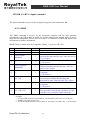
1
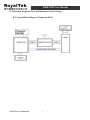
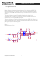
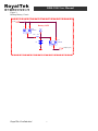
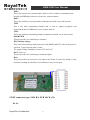
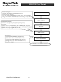
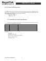
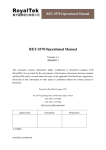
RDR-3200 User Manual RDR-3200 (Panasonic Gyro) User Manual Version 1.0 2009/06/02 This document contains information highly confidential to RoyalTek Company LTD (RoyalTek). It is provided for the sole purpose of the business discussions between customer and RoyalTek and is covered under the terms of the applicable NonDisclosure Agreements. Disclosure of this information to other parties is prohibited without the written consent of RoyalTek. Prepared by RoyalTek Company LTD. 4F, No. 188, Wen Hwa 2nd Rd., Kuei-Shan, Tao-Yuan 333, Taiwan TEL: 886-3-3960001 FAX: 886-3-3960065 Website: http://www.royaltek.com Email: http://www.royaltek.com/contact RoyalTek Confidential 1 RDR-3200 User Manual Content 1. Introduction....................................................................................................3 2. Product Feature ..............................................................................................3 3. Specification ..................................................................................................4 4. Reference design of Gyro and Odometer circuit design................................5 4.1 System Block Diagram (Panasonic SKU) ...........................................................5 4.2 Application Circuit...............................................................................................6 5. Interface .........................................................................................................8 5.1 Connector Type:20 Pin Header,2.0 mm pitch (J2).........................................8 5.2 RF connector type: SMA R/A PCB JACK (J1) ...................................................9 6. Product Picture.............................................................................................10 7. Mechanical Layout.......................................................................................11 8. SW Protocol .................................................................................................12 8.1 GPS output Protocol ..........................................................................................12 8.1.1 RoyalTek DR protocol – RTOEM,3 ...............................................................12 8.1.2 GGA-Global Positioning System Fixed Data .................................................13 8.1.3 GSA-GNSS DOP and Active Satellites ..........................................................15 8.1.4 GSV-GNSS Satellites in View ........................................................................17 8.1.5 RMC-Recommended Minimum Specific GNSS Data ...................................18 8.2 GPS DR (UART A) Input command ...........................................................19 8.2.1 $MMF .............................................................................................................19 8.3 CAN bus (UART B) protocol ............................................................................21 8.3.1 Speed, Reverse status input Message..............................................................21 8.3.2 GPS antenna detection output Message..........................................................22 8.4 NMEA Output Message...............................................................................23 9 Calibration of DR.........................................................................................23 9.1 Self calibration of DR ........................................................................................23 9.2 Calibration Criterion ..........................................................................................23 9.3 Calibration of DR using digital map information ..............................................23 9.4 Gyro Electric Characteristics .............................................................................23 10. Package Specification and Order Information...................................................25 11. Contact Royaltek................................................................................................25 12. Revision History ................................................................................................25 RoyalTek Confidential 2 RDR-3200 User Manual 1. Introduction RoyalTek RDR-3200 is the newest generation of RoyalTek GPS module integrated Dead Reckoning technology. The RDR-3200 includes dead reckoning sensors to track your vehicle's course when your GPS signal is blocked for example in urban areas or tunnels. If you lose GPS coverage in areas with tall buildings or tunnels, the RDR-3200 keeps on navigating. This document describes the recommended schematic and layout design of gyro and odometer circuit, and is designed to operate with RDR-3200 algorithm correctly. This document also describes the application of DR protocol and illustrates how to optimize the performance of DR using known digital map information. 2. Product Feature 20 parallel channels Screw holes type Newest generation of RoyalTek GPS module integrated Dead Reckoning technology Keep on producing an accurate position after loosing contact to the GPS satellites. Enhanced algorithm for navigation stability and minimizes the effects of GPS outages, And provide improved position accuracy in urban environments. Excellent sensitivity for urban canyon and foliage environments. 2.1 Product Applications Automotive navigation RoyalTek Confidential 3 RDR-3200 User Manual 3. Specification GPS Chipset Frequency Channel C/A Code chipset Fix time (Open sky) Accuracy - Star III GPS Gsc3f/LPX chipset - L1 1,575.42 MHz - 20 channels - 1,023 MHz - Reacquisition: less than 0.1s - Hot start: 1 sec - Warm start: 35 sec - Cold start: 35 sec - Position: within 10m for 90% - Velocity: 0.1m/s - NMEA 0183 - Default is Disable - Default WAAS is Disable - 18,000 meter maximum - 514 meter/second maximum - Silicon Lab C8051F353 Interface Protocol DGPS WAAS Altitude Velocity MCU Antenna Active Antenna RF - SMA R/A PCB JACK (J1) Connector - Option for any kind of RF Connector External Antenna - Recommend using 2.7V~3.3V input Voltage Power Voltage Type - DC +5V ± 2% Screw Hole type Antenna Detect function GPIO; Follow customer GPS antenna detector protocol Port 2 baud Rate: 38400bps 1: YES / 0:NO Interface Connector 20 Pin Header,2.0 mm pitch (J2) Male seat Physical and Environment Dimension - 71±0.3mm(L) x 40.8±0.3mm(W) x 18.3mm±0.3mm (H) Weight - ≦19.6(g) Temperature - Operating: -40 ~ 85℃ - Storage: -40 ~ 85℃ RoyalTek Confidential 4 RDR-3200 User Manual 4. Reference design of Gyro and Odometer circuit design 4.1 System Block Diagram (Panasonic SKU) RoyalTek Confidential 5 RDR-3200 User Manual 4.2 Application Circuit Figure 1 illustrates the proposed schematic diagram of Gyro, odometer and RDR-3200. RDR-3200 supports the Gyro, Panasonic. Please care about the ground partition design among Gyro circuit, RDR-3200 and odometer input. It would be better to use 2 kinds of ground. The input of odometer is around 12V typically. It transfers the voltage level to accommodate the I/O voltage level of RDR-3200. The photo coupling transistors also isolate the noise of car from the RDR-3200 system. The power of the gyro is 5Vwhich is different from the power of RDR-3200. Please use a separate analog ground for gyro. And please keep high speedy signal away from the signal path of gyro and power when doing layout. Figure 1. Odometer/Reverse Circuit V_5V V_5V R12 220 V_3V3 R13 220 U4 R47 R11 0 1k TP31 LTV817S 4 1 1 V_3V3 D1 R17 22K 2 3 1 4 2 3 1 R22 100K U5 R23 0 D2 R24 22K Q2 2SC2412K 2 1 Rev erse 3 1 TP32 C11 0.01uF RoyalTek Confidential R25 100K 1 1N4148 6 odometer_A/D rev erse_A/D 1N4148 C10 0.01uF 20 1 R15 Q1 2SC2412K 2 Odometer 0 3 R14 LTV817S R19 R18 0 270 RDR-3200 User Manual Figure 2. Backup Battery Circuit Battery SCH 1 2 V_3V3 D12 TP37 1 220 2 R40 1 3 1 1 RB705D D13 B1 3 2 RB705D PIN3(RTC_3V3) RoyalTek Confidential 7 RDR-3200 User Manual 5. Interface 5.1 Connector Type:20 Pin Header,2.0 mm pitch (J2) Pin NO 1 2 3 Signal Name 4 5 6 N.C GPS 5V RTC (Backup voltage) GPS 5V Reset Boot 7 I/O Description Characteristics I I I None connector +5V DC Power Input DC +5V ± 5%. User Supply DC +2.6 ~ DC +2.6 ~ +3.6V. +3.6V Current ≤ 10uA w/o battery +5V DC Power Input Reset (Active low) VIH > 2.3V VIL < 0.8V 3.15 ≥ VIH ≥ 1.995V - 0.3V ≤ VIL ≤ 0.855V Boot mode Back (Reverse) I Forward or Back 8 9 N.C Odometer I None connector Odometer 10 11 GND TXD1 (SiRF 3 TXD1) 12 RXD1 (SiRF 3 I RXD1) GND G TXD2 (SiRF 3 O TXD2) RXD2 (SiRF 3 I RXD2) GND G GND G GND G N.C N.C GPS_5V This is the DC power supply input pin for system. . 13 14 15 16 17 18 19 20 I I G O Forward (Hi level :>2V) Backward (Lo level: <0.8V) Input frequency<4k HZ Vih > 2V Vil<0.8V Reference Ground Ground VOL ≤ 0.715V NMEA (transmit) Car PC 2.85V ≥ VOH ≥ 2.375V (UAR1) 4800bps, 8 data bits, no parity, 1 stop bit - 0.3V ≤ VIL ≤ 0.855V NMEA (Receive) Car PC 3.15V ≥ VIH ≥ 1.995V (UAR1) Ground Reference Ground Can bus data (transmit) Vih > VDD-0.1V Vil<0.6V Car PC (UAR2) VDD:3.3V for MCU Can bus data (Receive) Vih > 2V Vil<0.8V Car PC (UAR2) Ground Reference Ground Ground Ground Reference Ground NC NC GND GND provides the reference ground . BOOT Set this pin to high for programming flash. RoyalTek Confidential 8 RDR-3200 User Manual RXD1 This is the main receiver channel and is used to receive software commands to the board from SIRFdemo software or from user written software. RXD2 This is the auxiliary receiving channel communicated with car pc with can bus TXD1 This is the main transmitting channel and is used to output navigation and measurement data to SiRFdemo or user written software. TXD2 This is the auxiliary transmitting channel communicated with car pc with can bus ODOMETER This pin provides for connecting to odometer. RTC (Backup voltage) This is the battery backup input that powers the SRAM and RTC when main power is removed. Typical current draw is 10uA. The supply voltage should be between 2.5V and 3.6V. BACK (Reverse) This pin provides for connecting to backward signal. Reset This pin provides an active-low reset input to the board. It causes the board to reset and start searching for satellites. If not utilized, it may be left open. 5.2 RF connector type: SMA R/A PCB JACK (J1) RF IN: RoyalTek Confidential 9 RDR-3200 User Manual This pin receives GPS analog signal. The line on the PCB between the antenna (or antenna connector) has to be a controlled impedance line (Microstrip at 50Ω). This pin can provide maximum power 30mA @ 2.85V for active antenna. 6. Product Picture TOP: Bottom: RoyalTek Confidential 10 RDR-3200 User Manual 7. Mechanical Layout RoyalTek Confidential 11 RDR-3200 User Manual 8. SW Protocol 8.1 GPS output Protocol The communication settings: Baud rate: 38400, n, 8, 1 The UARTA will output GPS NMEA 0183 V3.0 protocol and RoyalTek DR protocol. There are 4 type sentence will output as the follow table: NMEA Record GGA GSA GSV RMC Table 1-1 NMEA-0183 Output Messages Description Global positioning system fixed data GNSS DOP and active satellites GNSS satellites in view Recommended minimum specific GNSS data The RoyalTek DR protocols are NMEA like protocol to show the DR navigation and calibration information. 8.1.1 RoyalTek DR protocol – RTOEM,3 This sentence contains the navigation and calibration information of DR. The protocol is illustrated as follows: Item 1 2 3 4 5 6 7 8 9 10 11 12 13 14 15 Field $ RTOEM 3 GPS validated Gyro Bias Initial Status Odometer Scale Initial Status Gyro Input Status Odometer Input Status Sensor Capture Count Odometer Input Source DR Status Backward Status Antenna Detecting Gyro Input Voltage EKF Odometer scale RoyalTek Confidential Description Beginning of sentence Message Header Message ID Number of SV in use > 3 = 1, other is 0 1.Success, 0: Failed 1: Success, 0: Failed 1: Available, 0: no input 1: Available, 0: no input The count of data read count from MCU 1: CAN BUS,0: Vehicle’s Odometer PWM 4: Initialize, 3: GPS Mode, 2:DR Mode 1: Activated / 0: Normal 1: Available / 0: Abort Current Gyro Input voltage and scale is 500:1 The scale factor of odometer pulse. The scale is cm/pulse 12 RDR-3200 User Manual 16 Delta Angle 17 Odometer/CAN Bus Pulse Count 18 Delta Distance 19 Map Matching Status 20 *CC<CR><LF> Vehicle’s Cog per second (unit = degree), +: turn right, ‘-‘: turn left. The pulse count of last second of odometer sensor. The unit is pulse / second. The delta distance of last second. (unit=meter) 1: Received and executed a map matching sentence; 0: Not receive any map matching sentence. Check Sum and sentence termination delimiter. The algorithm of checksum calculation is same with the one to calculate NMEA checksum. Example: $RTOEM,3,1(X1),1(X2),1(X3),1(X4),1(X5),1(X6)0(X7)3(X8)0(X9)1(X10),831.95(X11), 29.78(X12),27.45(X13),77(X14),22.93(X15),0(X16) *50 X1: GPS is validated. X2: Gyro bias is initialized X3: Odometer scale is initialized X4: Gyro input source is available X5: Odometer input source is available X6: 1 time for capture sensor per X7: Odometer source is used X8: GPS mode is used X9: No backward is captured X10: Antenna is available X11: Gyro voltage is 831.95 / 500 = 1.6639 (V) X12: EKF odometer scale parameter is 29.78 (cm/pulse) X13: Delta angel for Device is turn right 27.45 (degree) X14: Odometer capture pulse count is 77 X15: Delta Distance for Device is 22.93 (meter) X16: No MMF command is accepted 8.1.2 GGA-Global Positioning System Fixed Data Table 1-3 contains the values of the following example: $GPGGA,161229.487,3723.2475,N,12158.3416,W,1,07,1.0,9.0,M, , , ,0000*18 Table 1-1 GGA Data Format Name Example Units Description Message ID $GPGGA GGA protocol header UTC Position 161229.487 hhmmss.sss Latitude 3723.2475 ddmm.mmmm N/S Indicator N N=north or S=south Longitude 12158.3416 Dddmm.mmmm RoyalTek Confidential 13 RDR-3200 User Manual E/W Indicator Position Fix Indicator Satellites Used HDOP W 1 07 1.0 MSL Altitude Units Geoid Separation Units Age of Diff. Corr. 9.0 M Diff. Ref. Station ID Checksum <CR><LF> 0000 *18 Value 0 1 2 3-5 6 RoyalTek Confidential M E=east or W=west See Table 1-4 Range 0 to 12 Horizontal Dilution of Precision meters meters meters meters second Null fields when DGPS is not used End of message termination Table 1-2 Position Fix Indicators Description Fix not available or invalid GPS SPS Mode, fix valid Differential GPS, SPS Mode, fix valid Not Supported GPS PPS Mode, fix valid Dead Reckoning Mode, fix valid 14 RDR-3200 User Manual 8.1.3 GSA-GNSS DOP and Active Satellites Table 1-5 contains the values of the following example: $GPGSA,A,3,07,02,26,27,09,04,15, , , , , ,1.8,1.0,1.5*33 RoyalTek Confidential 15 RDR-3200 User Manual Table 1-1 GSA Data Format Example Units Description $GPGSA GSA protocol header A See Table 1-6 3 See Table 1-7 07 Sv on Channel 1 02 Sv on Channel 2 …. Sv on Channel 12 1.8 Position Dilution of Precision 1.0 Horizontal Dilution of Precision 1.5 Vertical Dilution of Precision *33 End of message termination Name Message ID Mode 1 Mode 2 Satellite Used Satellite Used …. Satellite Used PDOP HDOP VDOP Checksum <CR><LF> Value 1 2 3 Value M A Table 1-2 Mode 1 Description Fix not available 2D 3D Table 1-3 Mode 2 Description Manual-forced to operate in 2D or 3D mode Automatic-allowed to automatically switch 2D/3D RoyalTek Confidential 16 RDR-3200 User Manual 8.1.4 GSV-GNSS Satellites in View Table 1-8 contains the values of the following example: $GPGSV,2,1,07,07,79,048,42,02,51,062,43,26,36,256,42,27,27,138,42*71 $GPGSV,2,2,07,09,23,313,42,04,19,159,41,15,12,041,42*41 Name Message ID Number of Messages1 Messages Number1 Satellites in View Satellite ID Elevation Azimuth SNR (C/No) …. Satellite ID Elevation Azimuth SNR (C/No) Checksum <CR><LF> Table 1-8 GSV Data Format Example Units Description $GPGSV GSV protocol header 2 Range 1 to 3 1 Range 1 to 3 07 07 Channel 1(Range 1 to 32) 79 degrees Channel 1(Maximum 90) 048 degrees Channel 1(True, Range 0 to 359) 42 dBHz Range 0 to 99, null when not tracking …. 27 Channel 4(Range 1 to 32) 27 degrees Channel 4(Maximum 90) 138 degrees Channel 4(True, Range 0 to 359) 42 dBHz Range 0 to 99, null when not tracking *71 End of message termination 1 Depending on the number of satellites tracked multiple messages of GSV data may be required. RoyalTek Confidential 17 RDR-3200 User Manual 8.1.5 RMC-Recommended Minimum Specific GNSS Data Table 1-9 contains the values of the following example: $GPRMC,161229.487,A,3723.2475, N,12158.3416,W,0.13,309.62,120598,,,A*10 Table 1-1 RMC Data Format Name Example Message ID $GPRMC UTC Position 161229.487 Status A Latitude N/S Indicator Longitude E/W Indicator Speed Over Ground Course Over Ground Date Magnetic Variation Variation sense 3723.2475 N 12158.3416 W 0.13 309.62 120598 Mode A Checksum *10 Units knots degrees Description RMC protocol header hhmmss.sss A=data valid or V=data not valid ddmm.mmmm N=north or S=south dddmm.mmmm E=east or W=west True Ddmmyy degrees RoyalTek Confidential E=east or W=west(Not Shown) A=Autonomous, D=DGPS, E=DR 18 RDR-3200 User Manual GPS DR (UART A) Input command The input command is used to let the navigation program send command to DR. 8.2.1 $MMF This MMF command is used to let the navigation program send the map matching information to the DR module to update the current position and azimuth angle of device using known information. Please refer to section 2.2 Calibration of DR using digital map information for further information. $MMF, Delta_Latitude,A,Delta_Longitude,A,Delta_ Cog,A*ck<CR><LF> Item 1 $ 2 MMF Field Length 1 5 3 Delta Latitude (ddddddd) 7 4 A 1 5 Delta Longitude (dddddddd) 8 6 A 1 7 Del_Cog 4 8 A 1 9 *CC<CR><LF> 5 Description Beginning of sentence Message Header The correction of latitude value to calibrate DR position that generated by map. Value the unit is 1.0e-6 degree A: use above value to calibrate the DR Latitude V: Do not use. The correction of longitude value to calibrate DR position that generated by map. Value the unit is 1.0e-6 degree A: use above value to calibrate the DR Longitude V: Do not use. The correction angle (COG) of current movement to calibrate DR Heading that generated by map. Value the unit is 0.1 degree. A: use above value to calibrate the DR Longitude V: Do not use. Check Sum and sentence termination delimiter. The algorithm of checksum calculation is same with the one to calculate NMEA checksum. Example: Example: => If current DR position is (24.106928 N, 120.299588 E) with COG=213.19 degree => $MMF,156,A,288,A,10,A*2D => It will set the DR position to (24.119842 N, 120.301837 E) with COG = 214.19 degree. RoyalTek Confidential 19 RDR-3200 User Manual Transfer Examples: Original: (24.106928,N,120.299588,E) (213.19) Result: (to unit = degree) Lat = 24 + 10/60 + 69.28/3600 (if S is used, Lat * ‐1.0) = 24.185911 Long = 120 + 29/60 + 95.88/3600 (if S is used, Long * ‐1.0) = 120.5100 Get current GPS Position (Unit = DD.MMSSSS) Converter GPS Info Format (Unit = degree) Command Description: Parameter: (156,A(para1),288,A(para2),10,A(para3)) Exposition: If para1 = ‘A’, Lat = Lat(24.1859) + 156 * 0.000001(unit = degree) If para2 = ‘A’, Long = Long(120.5100) + 288 * 0.000001(unit = degree) If para3 = ‘A’, Cog = Cog(213.19) + 10 * 0.1 Retrieved MMF Command Message Updated GPS Position by Input MMF Message Description: Lat Format: DD.MMSSSS, N/S indicator (If lat value < 0.0, ‘S’ is used. Other is ‘N’) Long Format: DDD.MMSSSS, E/W indicator (If long value < 0.0, ‘W’ is used. Other is ‘E’) Cog: unit = degree Converter GPS Info Format (Unit = DD.MMSSSS) Waiting for next MMF Command RoyalTek Confidential 20 RDR-3200 User Manual 8.3 CAN bus (UART B) protocol The RDR-3100 provides a second port to receive the speed and reverse message from the input source. If the module receives the following input message then the DR module will stop reading the speed and reverse message from MCU. The communication settings: Baud rate: 38400, n, 8, 1 Update rate: 1 Hz 8.3.1 Speed, Reverse status input Message This sentence contains the speed and reverse information that read from CAN bus. The protocol is illustrated as the following: Item Field Description 1 $ Beginning of the sentence 2 PSRF121 Message Header 3 Speed 4 Reverse High-normal / Low - activated 5 *CC<CR><LF> Example: Example: $PSRF121, 100, 1*25 Speed = 100 * scaled meter/second Reverse isn’t activated Checksum = 25 RoyalTek Confidential 21 RDR-3200 User Manual 8.3.2 GPS antenna detection output Message This sentence contains the GPS antenna detector information which read from GPS module and send to the CAN bus. The protocol is illustrated as follows: Item 1 2 Field $ PSRF122 3 GPS antenna status 4 *CC<CR><LF> Description Beginning of sentence Message Header 1: antenna connected 0: antenna not connected Check Sum and sentence termination delimiter. The algorithm of checksum calculation is same With the one to calculate NMEA checksum. Example: $PSRF 122,1*3B<CR><LF> GPS antenna connected Check sum= 0x3B. RoyalTek Confidential 22 RDR-3200 User Manual 8.4 NMEA Output Message 9 Calibration of DR 9.1 Self calibration of DR RDR-3100 calibrates the Gyro bias and odometer scale using the information of GPS satellites automatically. It also updates the position and azimuth using GPS navigation information automatically. Customer is not required to calibrate the Gyro bias and odometer scale factor. In respect to the position and azimuth angle, RDR-3100 DR provides a protocol, which is used to calibrate the position and azimuth angle using digital map. 9.2 Calibration Criterion •Keep vehicle in static with 15 seconds at least after power on to retrieve gyro initial bias •During normal operation, the calibration of gyro and odometer scale take place automatically during periods of good GPS reception. 9.3 Calibration of DR using digital map information The DR is used to output the navigation data when GPS signal is absent or poor. The longer time of losing GPS signal, the Gyro precision and odometer would become worse. The best way to have better DR performance is to use the digital map information. Once the map matching completed, it could provide useful information for DR algorithm to continuously output the accurate navigation information as possible. The PROYRESET is designed for this purpose. Navigation application can reset the DR position and COG especially when no or poor GPS signal occurs. Because digital map provides very accurate and stable positioning information, to get longer and more accurate DR output, please use PROYRESET to achieve it. 9.4 Gyro Electric Characteristics Gyro Chipset RoyalTek Confidential - Panasonic EWTS86 23 RDR-3200 User Manual Operation voltage Range Temperature Range Zero point voltage Sensitivity Frequency response(7Hz) Output voltage range Output noise RoyalTek Confidential - +5±0.25 V - -40 ~ 85℃ - +2.5±0.4V - 25mV/(°/S) - >–4dB - 0.3~4.7V - <10mVpp 24 RDR-3200 User Manual 10. Package Specification and Order Information 11. Contact Royaltek Headquarter: Address: 4F., No.188, Wen Hwa 2nd Rd., Kuei Shan, Tao Yuan 333, Taiwan TEL: 886-3-3960001 FAX: 886-3-3960065 Web Site: http://www.royaltek.com Web Site Customer Service: http://www.royaltek.com/contact 12. Revision History Revision Date Number 1.0 2009/06/02 Author Change notice May Chen Initial Release Copyright © 2009, RoyalTek Company Ltd. RoyalTek Confidential 25