1
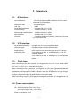
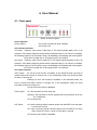
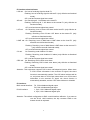
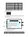
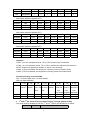
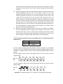
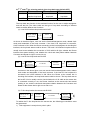
RC 903-V35FE1 V.35 to Fractional E1 Interface Converter User Manual 1. Cautions Warning . Only trained and qualified personnel should be allowed to install, replace or service this equipment. RC903-V35FE1 provides Synchronous Digital Interface complying with the ITU standard. Before power on, the V.35 cable must be well connected. It is strictly forbidden to hot-swap V.35 cable when the converter and the equipment connected by V.35 cable are both power on. RC903-V35FE1 is integrated equipment. Move carefully and do not disassemble or mend it without the guidance of Dynamix technical engineer with the anti-static procedures. The equipment must be grounded. Do not disassemble the equipment by yourself. It may cause unrecoverable damage. Dynamix will not be responsible for the damage by this. 1 Contents 1. Cautions..................................................................................................................... 1 2. Overview .................................................................................................................... 3 2.1. 2.2. 2.3. 3. 3.1. 3.2. 3.3. 3.4. 3.5. 3.6. 4. 4.1. 4.2. 4.3. 4.4. 4.5. 5. 5.1. 5.2. 5.3. 5.4. Introduction............................................................................................................. 3 Main feathers:......................................................................................................... 3 Equipment description ............................................................................................ 3 Parameters ................................................................................................................ 5 E1 interface: ........................................................................................................... 5 V.35 interface: ........................................................................................................ 5 Cable type: ............................................................................................................. 5 Power consumption: ............................................................................................... 5 Structure: ................................................................................................................ 6 Ambience ............................................................................................................... 6 User Manual............................................................................................................... 7 Front panel ............................................................................................................. 7 Back panel.............................................................................................................. 9 Bottom Dip Switches ............................................................................................ 10 Inside Jump pin definition ..................................................................................... 16 Basic Connection ................................................................................................. 17 Equipment installation and Preparation.................................................................... 20 Installation preparation ......................................................................................... 20 Cautions when the power is on ............................................................................ 20 Placement ............................................................................................................ 21 Test of connection ................................................................................................ 21 6. Troubleshooting ....................................................................................................... 22 7. Appendix .................................................................................................................. 24 Explanation of CBL-V35-M34F/M34M-D cable ............................................................... 24 Explanation of CBL-V35-M34M/M34M-X-D .................................................................... 24 2 2. Overview 2.1. Introduction RC 903-V35FE1 is an interface converter for V.35 equipment based on E1 network transmission. With the growing utilization of E1 resources, many data transmission solutions using E1 link are accepted by users. RC 903- V35FE1 is standalone equipment, with built-in power supply, and can be placed on the table. It provides signal conversion between V.35 and fractional E1, and can be used in pairs or alone. This equipment will not change the data from V.35 interface. 2.2. Main feathers: 1) Provide a V35 synchronous digital DCE interface complying with ITU standard. 2) Provide an E1 interface complying with ITU standard and both 75Ω (unbalanced BNC interface) and 120Ω (balanced RJ-45 interface) are available for our users. 3) Complete E1 line alarm including both local and remote line alarm. 4) Provide local and remote loop-back test function, which can help easily analysis the bit rate error. 5) Support E1 fractional and transparent frame modes. When it is in the fractional mode, the time slot can be allocated at will. 6) Provide 3 clock modes: Master clock, Slave clock, and V35 terminal clock. 7) When working in pairs in the fractional mode, the time-slot allocation of the local equipment can automatically follow that of the remote equipment. 8) Internal bit error test unit can analysis and test the line with various loop-bake modes. 9) In the fractional mode, PCM30 and PCM31 can be chosen and CRC4 function is self-adaptive. 10) Provide phase adjustment function for the V35 receiving data. 11) Provide fault pass through function: informing the V35 interface of the E1 fault, and estimating E1 fault on the Router. 12) Use very large scale ASIC chip with low power consumption, four-layer circuit board design, and high reliability. 2.3. Equipment description RC903/904-V35FE1series converter includes the following models: Part number Description RC903-V35FE1-AC Standalone , one E1 interface ( 75Ω unbalanced or 120Ω Balanced), one standard V35 DCE interface (ISO2593 M34 Female), 220VAC 3 RC903-V35FE1-DC Standalone , one E1 interface ( 75Ω unbalanced or 120Ω Balanced), one standard V35 DCE interface (ISO2593 M34 Female) , -48VDC RC904-V35FE1 Module, one E1 interface(75Ω unbalanced), one standard V35 DCE interface, HDB26 male(transform to ISO2953 M34 female through attached cable) RC904-V35FE1-BL Module, one E1 interface (120Ω balanced, one standard V35 DCE interface) HDB26 male ( transform to ISO2953 M34 female through attached cable) The models in shadow of the above table are included in this manual. The equipment in the above table can be used in pairs or alone. 4 3. Parameters 3.1. E1 interface: Input impedance: Two 75Ω (unbalanced BNC interface) and one 120Ω (balanced RJ-45 interface) Interface bit rate: 2048Kbps±50ppm Line code: HDB3 Physical characteristics: Complies with ITU-T G.703 Frame structure: Complies with ITU-T G.704 Pass-through characteristics: Complies with ITU-T G.823 Jitter tolerance: Complies with ITU-T G.823 Functions: Completed link alarm indication, Fault Pass Through (FPT) and auto-reset 3.2. V.35 interface: Physical characteristics: Connector type: Working mode: Interface bit rate: Complies with ITU V.35 interface standard ISO2593 female connector (M34 female) DCE (support cross-connection with other DCE device) V.35 interface bit rate is N×64Kbps (N=1~31 ) at E1 fractional pattern; V.35 interface bit rate is 2048Kbps at E1 transparent pattern 3.3. Cable type: When connecting to the BNC interface, it is suggested to use SYV 75-2-2 coaxial cable. SYV 75-2-1 or SYV 75-1-1 could also be chosen. When connecting to RJ-45 interface, it is suggested to use 0.6mm (22AWG) twisted pair. When connecting to DTE equipment such as Router through M34 interface, it is suggested to use special DTE cable for Router. When the DTE cable is not long enough, Dynamix can provide CBL-V35-M34F/M34M- D extension cable. When connecting to other DTE equipment through M34 interface, it is suggested to use cross-connect cable CBL-V35-M34M/M34M-X-D provided by Dynamix. 3.4. Power consumption: AC: 220V/50Hz (input ranges from 165 to 265V) DC: -48V (input ranges from -36 to -72V) +24V (input ranges from +18 to +36V) Power consumption: ≤ 5W 5 3.5. Structure: Standalone Dimensions: 120(W)*39(H)*155(D) mm 3.6. Ambience Operation temperature: 0~45°C Operation humidity: ≤90% (25 °C) 6 4. User Manual 4.1. Front panel Sketch of the front panel Power Indicator: Power (PWR): On: power is working in good condition Off: Power is off. V35 interface Indicator: TD Green: Flashing: when there is data flow of TD signal (sending data) at the V.35 interface. The Flashing frequency differs with the interface rate of V.35. When it is 64Kbps, the Flashing frequency is the lowest; when it is 2048Kbps, the Flashing rate is the highest. Off: there is no data flow of TD signal at the V.35 interface. RD Green: Flashing: when there is data flow of RD signal (receiving data) at the V.35 interface. The Flashing frequency differs with the interface rate of V.35. When it is 64Kbps, the Flashing frequency is the lowest; when it is 2048Kbps, the Flashing rate is the highest. Off: there is no data flow of RD signal at the V.35 interface. Test status Indicator: TEST yellow: On: bit error test function is enabled. In the fractional mode, the local or remote loop-back function is correctly set. In the transparent mode, the local loop-back function is correctly set. Flashing: bit error test function is enabled. In the fractional mode, the local or remote loop-back function is wrongly set. In the transparent mode, the local loop-back function is wrongly set. Off: bit error test function is disabled. LOOP yellow: On: The loop-back is at the local site. Flashing: The loop-back is at the opposite site (only effective when the E1 is fractional) Off: No loop-back PAT yellow: On: when receiving pseudo random series from the BERT unit, and there is no bit error on line. Off: when receiving pseudo random series from the BERT, but when there is bit error on line, it goes off for at least 1 second. Off: Bit error test function is disabled. 7 E1 interface alarm Indicator: LOS red: On: loss of receiving signal at local E1; Flashing: loss of receiving signal at remote E1 (only effective at fractional mode); Off: Local and remote signal are normal AIS red: On: Receiving all ‘1’ AIS alarm at the local E1 Flashing: Receiving all ‘1’ AIS alarm at the remote E1 (only effective at fractional mode); Off: Local and remote signal are normal LOF red: On: Receiving Loss of frame LOF alarm at the local E1 (only effective at fractional mode); Flashing: Receiving Loss of frame LOF alarm at the remote E1 (only effective at fractional mode); Off: Local and remote signal are normal LOMF red: On: Receiving Loss of Multi-frame LOMF alarm at the local E1 (only effective at multi-fractional mode) Flashing: Receiving Loss of Multi-frame LOMF alarm at the remote E1 (only effective at multi-fractional mode); Off: Local and remote signal are normal CV red: On: Receiving code violation CV alarm Flashing: Receiving code violation CV alarm (only effective at fractional mode); Off: Local and remote signal are normal CRC red: On: Receiving CRC4 check error alarm Flashing: Receiving CRC4 check error alarm (only effective at fractional mode); Off: Local and remote signal are normal Attention: This equipment supports CRC4 check self-adaptive function. When there is CRC4 check information in the received E1 signal, the check function is automatically enabled. The CRC alarm indicator will be on, only when there is CRC4 fault; when there is no CRC4 check information in the received E1 signal, the check function is automatically disabled, and the CRC alarm indicator is disabled. E1 interface: BNC coaxial interface: TX, 75Ω unbalanced signal output RX, 75Ω unbalanced signal input RJ-45 interface: 1, 2 pin, 120 Ω balanced signal output 4, 5 pin, 120 Ω balanced signal input Attention: The default configuration is BNC coaxial interface effective. If you want to use the RJ-45 120Ω interface, the dip converter SW6 on the bottom should be adjusted. 8 4.2. Back panel Sketch of the back panel of AC equipment Sketch of the back panel of DC equipment Power interface: AC interface: standard 3 phase AC power supply interface. Please guarantee that it is correctly grounded. DC interface: DC ports: -48V, PGND, BGND, Please make sure that PGND is grounded; BGND is connected to 0V of DC power supply; -48V is connected to -48V of DC power supply. V.35 interface: The left figure shows V.35 interface ISO 2593 connector. Our converter adopts DCE Connector Face – 34-Pin Female connector, which can be connected with DTE cable. The definition of interface is shown below: I — Input; O— Output Input/Output Pin number Chassis Ground — CGND - A Signal Ground — GND - B Receive Data (A) — RD(A) O R Receive Data (B) — RD(B) O T Receive Timing (A) — RCK(A) O V Receive Timing (B) — RCK(B) O X Send Data (A) — TD(A) I P Pin name 9 Send Data (B) — TD(B) I S Send Timing (A) — TCK(A) O Y Send Timing (B) — TCK(B) O AA Terminal Timing (A) — SCTE(A) I U Terminal Timing (B) — SCTE(B) I W Request to Send — RTS I C Clear to Send — CTS O D Data Set Ready — DSR O E Data Carrier Detect — DCD O F Data Terminal Ready — DTR I H 4.3. Bottom Dip Switches ON OFF ON DIP 12345678 There are 6 groups of 8-bit DIP switches. The positions of the six switches are called SW1, SW2, SW3, SW4, SW5, and SW6. Every switch is like the above figure. OFF is below, and ON is above. There is a DIP switches explanation table on the rear board as follows: V35 Interface Power supply Interface Timeslot configuration switch SW1 to SW4 The ‘√’ means enable, and ‘×’ means disable. SW1 switch definition (default OFF) Definition 1st bit 2nd bit 3rd bit 4th bit 5th bit 6th bit 7th bit 8th bit Frame TS1 TS2 TS3 TS4 TS5 TS6 TS7 10 format* ON Fractional √ √ √ √ √ √ √ OFF Transparent × × × × × × × SW2 switch definition (default OFF) 1st bit 2nd bit 3rd bit 4th bit 5th bit 6th bit 7th bit 8th bit Definition TS8 TS9 TS10 TS11 TS12 TS13 TS14 TS15 ON √ √ √ √ √ √ √ √ OFF × × × × × × × × 4th bit 5th bit 6th bit 7th bit 8th bit SW3 switch definition (default OFF) 1st bit 2nd bit 3rd bit Definition TS16* TS17 TS18 TS19 TS20 TS21 TS22 TS23 ON √ √ √ √ √ √ √ √ OFF × × × × × × × × 4th bit 5th bit 6th bit 7th bit 8th bit SW4 switch definition (default OFF) 1st bit 2nd bit 3rd bit Definition TS24 TS25 TS26 TS27 TS28 TS29 TS30 TS31 ON √ √ √ √ √ √ √ √ OFF × × × × × × × × Attention: If SW1-1 is in the transparent mode, TS1 to TS31 switches are not effective. If SW1-1 is in the fractional mode, TS1 to TS31 switches are effective and cannot be all OFF. At least one timeslot is enabled, or else it is not fractional. If SW3-1(TS16) is enabled, the equipment is working under the PCM31 mode. If SW3-1(TS16) is disabled, the equipment is working under the PCM30 mode. Function selecting converter SW5: The ‘√’ means enable, and ‘×’ means disable. SW5 converter definition 1st bit Definition Timing Clock 1 2nd bit 3rd bit 4th bit 5th bit 6th bit 7th bit 8th bit Timing TS_FLOW BERT RX CLK ALOOP DLOOP RLOOP clock2 Time slot Bit error phase Local V35 Local E1 RemoteE1 Line test port Line follow loop-back* loop-back* loop-back* ON * * √ √ Negative √ √ √ OFF * * × × Positive × × × 1. 1st and 2nd bit: clock selecting switch Timing1, Timing2 (default all ON) The clock mode is decided by both the 1st and 2nd switch, the definition is as follow: 1st bit 2nd bit Clock mode 11 OFF OFF Master clock (internal timing) OFF ON ON OFF V.35 Terminal clock ( followV.35 interface timing ) ON ON Slave clock (followE1 line timing) 2. 3rd bit: selecting switch for auto follow function TS-FLOW (default OFF) 3rd bit Timeslot auto follow function ON Enable OFF Disable To realize the setting of local timeslot bandwidth to follow the remote site, the following pre-conditions must be guaranteed: 1) This equipment is used point to point in pairs. 2) There is no PCM equipment occupying Sa bit connecting in series in the E1 link 3) The local equipment should be set to the slave clock mode. After fulfilling the above condition, you can set the auto-follow switch of the local equipment to ‘ON’ to enable the auto-follow function. The timeslot occupying and frame mode (PCM30/PCM31) setting of the local equipment will automatically follow the remote equipment. 3. 4th bit: selecting switch for bit error test function BERT (default OFF) 4th bit Inner bit error test function ON Enable OFF Disable There is an internal bit error test unit in this equipment. Its main function is to produce a pseudo random series in the format of 2E15-1-Std, which will be sent to the E1 line. User could load this series to proper data channel through configuration, and then with multiple loop-back function, the returned series can be checked by the equipment. The result will be shown on the PAT indicator on the front panel. When bit error is detected, the PAT indicator will be off for at least 1 second. If there is no new bit error, PAT indicator will return to the on status. If the bit error test function is on, test series will be inserted into the data channel used by the client. This function can be used both in the fractional and transparent mode. When this function is in use, business on the V.35 interface will stop. Attention: (1) Bit error test function could be combined with multiple loop-back for testing. When the local V.35 interface loop-back function is not enabled, you can use coaxial cable to make a loop-back at the E1 interface on the local equipment, which means testing the local equipment. In this situation, the TEST indicator is Flashing, the LOOP indicator is OFF, and the PAT indicator is ON, 12 (2) (3) which means that it has receive the correct test bit. If you choose to set the loop-back of the remote E1 line RLOOP, it means testing the whole process of signal. When testing the local E1 loop-back DLOOP, the bit error test function at the remote equipment and the local E1 loop-back function at the local equipment DLOOP should be on. It means that the test bit sent by the remote equipment loops back on the local equipment. At this time, if the remote and local equipment are both working in the transparent mode, the TEST indicator at the remote equipment should be Flashing, the LOOP indicator is off and the PAT indicator is on, which means that it has received the right test bit; if the remote and local equipment are working in the fractional mode, the TEST indicator at the remote equipment should be on, the LOOP indicator is Flashing and the PAT indicator is on, which means that it has received the right test code. When the loop-back ALOOP function at the local V.35 interface is enabled, the local equipment must be working in the Master clock mode or V.35 terminal clock mode, or else, it will not work normally. At this time, the test code returns to the internal of the equipment for check before it is sent out of the E1 interface. It means testing some function of the equipment. 4. 5th bit: selecting switch of the received data phase of V.35 RX CLK phase (default OFF) 5th bit RX CLK phase ON Negative OFF Positive RX CLK phase selecting provides different options according to the relation between V.35 clock of different brand Router and the data phase When RX CLK is positive, it passes the test on the V.35 synchronizing WAN interface of Cisco Router. RX CLK positive: data is sent to RD signal when the RX CLK clock is at the negative edge. RX CLK RD RX CLK negative: data is sent to RD signal when the RX CLK clock is at the positive edge. RX CLK RD Attention: The phase relation of TX CLK and TD is adjusted automatically. 13 5.6th 7th and 8th bit: selecting switch of the loop-back type (default OFF) 6th bit 7th bit 8th bit ON Local V35 interface loop-back Local E1 line loop-back Remote E1 line loop-back OFF No loop-back No loop-back No loop-back The loop-back test function is the assistant function for the user to adjust equipment and test the link. The client could set the type of loop-back according to different needs to realize different test functions. (1) Local V.35 interface loop-back test ALOOP DTE or V.35 bit error tester V.35 Local Converter E1Channel As shown in the above figure, user can set the fractional/transparent mode, related clock mode and bandwidth of the local converter. If the local V.35 loop-back is successful, LOOP indicator is ON. When the Router connecting to the local equipment is checking the interface, the loop-back status could be shown. The local V.35 interface loop-back test is usually used to test whether the connection of V.35 cable is all right, whether the Router interface has started working, and whether the clock and data phase relation between Converter and Router is right or not and so on. (2) Local E1 line loop-back test DLOOP DTE V.35 Local Converter Remote Converter E1Channal DTE orV.35bit V.35 error tester As shown in the above figure, user can set the fractional/transparent mode, related clock mode and bandwidth of the local converter. If the local E1 line loop-back is successful, the LOOP indicator is ON. When the Router at the remote site is checking the interface; the loop-back status could be shown. The loop-back test at the local E1 line is usually used to check whether the V.35 cable at the remote site is connected correctly or not, the Router interface at the remote site has started working or not, and the clock and data phase relation between the Converter and Router at the remote site is right or not and so no. (3) E1 line loop-back at the remote site RLOOP DTEorV.35 Bit error Tester V.35 Local Converter E1Channel Remote Converter To realize the E1 line loop-back at the remote site, the following pre-conditions must be guaranteed: 1) This equipment is used point to point in pairs. 14 2) There is no PCM equipment occupying Sa bit connecting in series in the E1 link 3) The local and remote equipment should not all be set to the transparent mode. As shown in the above figure, if the above conditioned is fulfilled, the related clock mode and bandwidth could be set. If the connection of E1 is correct, the local LOOP indicator is Flashing, which means that the remote E1 interface loop-back is successful. When the Router at the local site is checking the interface, the loop-back status could be shown. Switch for function selection SW6: SW6 switch definition: 1st bit Definition 2nd bit 3rd bit 4th bit Fault Reserved Reserved Reserved pass through ON Enable OFF Disable Normal Normal Normal 5th bit 6th bit 7th bit 8th bit Selection of the type of E1interface impedance E1 interface type-user could set according to practical application. The default is 75ΩBNC. 1. 1st bit: Selecting switch for fault pass through (default OFF) 1st bit Fault pass through ON Enable OFF Disable When the fault pass through function is enabled, the E1 sending and receiving side alarm is transmitted to DCD and CTS signal of the V.35 interface. When the fault pass through function is disabled, the DCD and CTS signal of the V.35 interface is always effective. If there is local alarm on the Converter, it means that there is fault at the E1 receiving side, therefore the DCD signal at the V.35 interface will be closed, and there is reflection at the DTE equipment. If there is remote alarm on the Converter, it means that there is fault at the E1 sending side, therefore the CTS signal at the V.35 interface will be closed, and there is reflection at the DTE equipment. The DSR signal of this equipment is effective after power on. 2. 2nd 3rd and 4th bit: Reserved switch (default OFF) These converters are reserved configuration switches for test. When the equipment is working, they should all be in the OFF status. 3. 5th 6th 7th and 8th bit: selecting switch for the type of E1 interface impedance. (Default ON ON ON OFF) 75Ω BNC unbalance interface effective effective 5th bit 6th bit 7th bit ON ON ON 120Ω 8th bit 5th bit RJ-45balanced 6th bit 7th bit interface 8th bit ON OFF OFF 15 OFF OFF 5th bit: sending side ‘TX-grounded; 6th bit: receiving side ‘RX-grounded; 7th bit: impedance adjustment at the receiving side 8th bit: impedance adjustment at the sending side Attention: Set according the above table, or else the E1 interface will be abnormal. 4.4. Inside Jump pin definition When the user want to adjust the internal jump pin, please do it under the guidance or agreement of Dynamix technical engineer. Usually it is not necessary; unless it is in sever environment or disturbance. After opening the case, you can see two groups of Jump pin (JP2 and JP3) on the upper layer of the circuit board. Its position, order of pin and default configuration is as follow: Definition of Jump pin: JP2 1:PGND protection ground 2:BNC_GND BNC screened layer 3:GND working ground The default setting is 1-2 pins short-circuited. JP3 1:PGND protection ground 2:GND working ground 3:NC No definition The default setting is 1-2 pins short-circuited. 16 4.5. Basic Connection The topological figures here are just for reference, users can design it according to practical application. The figures only take RC903-V35FE1 standalone converter as an example. 1) Point-to-point fractional E1 mode in “Master clock — Slave clock” structure (Master clock) (Slave clock) As the above figure shows, when connecting Routers or other equipment with V.35 interface using point-to-point pattern, Routers are required to work at DTE mode. For the convenience of installation and preparation, users can set Master Clock Mode in local converter and Slave Clock Mode in remote converter, and the clock source should be in local converter. 17 When using “Master Clock — Slave Clock” connection structure, if DXC and MUX devices are connected in series in E1 link, then DXC, MUX and remote converter should be at Slave Clock Mode (following E1 link clock). 2) Point-to-point fractional E1 mode in “Terminal clock — Slave clock” structure (Terminal clock) (Slave clock) (Clock source) When remote DTE equipment has to follow the clock phase of local DTE equipment, which is to say, TX CLOCK of local DTE is internal clock source, users can set Terminal Clock Mode in local converter, and Slave Clock Mode in remote converter, and must configure clock frequency at V.35 interface of local DTE equipment. When using “Terminal clock — Slave clock” connection structure, if DXC and MUX devices are connected in series in E1 link, then DXC, MUX and remote converter should be at Slave Clock Mode (following E1 link clock). 3) Point-to-point fractional E1 mode in “Slave clock — Slave clock” structure (Clock source) (Slave clock) (Slave clock) When using Slave Clock Mode at both sides, it is required to ensure that the clock source is provided by DXC, MUX or other PCM fractional E1 equipment in the E1 link, and there is only one clock source in the E1 link. 4) Extended connection type In this connection type, the converter is not used in pairs, but connected with equipment of 18 other manufactures. ADM If Routers with E1 interface are used at remote side, users are required to first confirm all the parameters of E1 link, such as fractional/transparent E1, PCM30/31, CRC enable/disable, clock relations, bandwidth distribution and time slot usage etc. If any one of them does not match the setting of the converter, there will be problems in connection. In this case, if devices at both ends work in fractional E1 mode, usually the clock relation is easily ignored. It is suggested that first make sure which device the clock source is on, then devices at other end should follow the clock on the E1 link. 19 5. Equipment installation and Preparation 5.1. Installation preparation Make sure that the E1 line cable matches the equipment model connected to it. The default effective interface is 75Ω BNC. If user wants to use BALANCED interface, please set the 6th group of dip-switches on the bottom. Usage of E1 balanced signal line Definitions of 120Ω balanced interface are as follows: 1st pin PIN Title 8th pin 1 2 3 4 5 6 7 8 TD+ TD- Not in use RD+ RD- Not in use Not in use Not in use Input+ Input- Definition Output+ Output- When 120Ω balanced interface connects with other devices, it is required to make sure of the pin definition of other devices. The pin connection method of twisted-pair on both ends is shown as follow: RC series converter BALANCE-RJ45 interface E1 TD TD RD RD transmission device balanced Signal output Signal output Signal input Signal input Attention: When connecting the twisted-pair, TD and TD should be twisted in pairs, and so do RD and RD . 5.2. Cautions when the power is on Hot-swapping V.35 interface is forbidden It is suggested that the protecting ground (middle of the adapter) be connected first when using DC –48V device. Note that inverse connection of positive and negative 20 polarity is strictly forbidden. When the equipment is on power and there is no equipment connecting to the V.35 interface, the AIS indicator is on in the transparent mode. This is normal. When the TD and RD indicators is Flashing, it is normal. 5.3. Placement The interface converter should be placed in equipment room, which must be kept clean and air-conditioned. Please set the clock mode, bandwidth configuration right, bandwidth setting at the Master side and other parameters according to different connection scheme. 5.4. Test of connection Make sure that no alarm shows on local equipment Check if local DTE equipment can process data communication with remote equipment If the data communication cannot be processed, then test it step by step as follow: 1) Process V.35 port local loop-back test, referring to later part of this manual, introduction to extended switch setup. If Router indicates success of loop-back test, the V.35 port is proved in good condition; if Router does not indicate loop-back, first check clock mode, bandwidth setting of local converter and try to adjust TX CLK and RX CLK phase select switch. 2) After successfully finishing the first step, check if communication in the E1 link works properly. If converters work in pairs, and No.0 time slot is not blocked in the E1 link, then remote loop-back test can be processed. If remote E1 port loop-back test is successful, then local RLP indicator is on, local Router should indicate successful loop-back. 3) If Dynamix converter does not work in pairs, then it is required to set parameters of E1 interface of other brand equipment consistent with settings of Dynamix local converter. Parameters include PCM30/31 format, CRC enable/disable, matching of clock mode etc. After these, please pay attention to the engrossment of V.35 data in frame structure. 4) After finishing the second step (or make sure the settings of the third step is completely correct), the communication in the E1 link between local and remote side should be in good condition. In this case, if remote V.35 interface is connected properly, but it still cannot communicate properly, please adjust the phase option of TX CLK or RX CLK at remote side. 21 6. Troubleshooting If there are any problems during installation and operation, please try to solve them according to the following suggestions. If the problems still exist, please contact distributors for help. Power (PWR): indicator OFF Answer: Please check if there is any fault with power supply. Loss-of-Signal (LOS) alarm in E1 link: indicator ON Answer: LOS alarm caution that your E1 interface cannot receive signal. Please check if the input cable is properly connected. If using 120Ω twisted-pair interface, please check if the line sequence is correct. Please also check if transmitting and receiving cables are reversely connected, and avoid hot swapping. Process local loop-back test, if there is still alarm, thus it indicates that the E1 interface of converter has been damaged. Alarm indicator for the error of E1 receiving signal (AIS, LOF, LOMF, CV, CRC) ON Answer: It means that there is error of received signal in the E1 link. Please check the line of E1 receiving side and the E1 frame mode parameters of the opposite equipment. Alarm indicator for the error of E1 receiving signal (AIS, LOF, LOMF, CV, CRC) Flashing Answer: It means that the E1 receiving side of the remote equipment, in other words, the sending side of the local equipment has some problem. Severe packet loss of the equipment: Answer: The possible reasons for severe packet loss are: 1. Incorrect clock mode setting 2. Check V.35 interface status of the Router, if there are data errors of input and output, then it indicates that TX CLK and RX CLK phase relationship need to be adjusted. This problem can be located by doing local V.35 interface loop-back test. 3. Cable loose at E1 port or wrong line sequence. 4. The 75Ω cable is not strictly grounded. It will cause disturbance. Compatibility with equipment of other brands Answer: RC903-V35FE1 can cooperate with similar products of other brands, and also can cooperate with Routers with fractional E1 interface. It is needed to ensure they are using same time slot engrossment and same setting of PCM30/31 and CRC. However, Passive Bandwidth Control function and E1 loop-back test of remote converter cannot be used. 22 Compatibility with other V.35 Dynamix products Answer: RC903-V35FE1 and RC904-V35FE1 can cooperate with other Dynamix products that have similar functions, such as followings: 1. SUBM-FV35 V.35 module which can be installed in the standalone extendable Multiplexer. 2. RC800-30B-FV35, N x 64K V.35 interface PDH fiber-optic multiplexer, equipped with all the functions of RC903-V35FE1 and RC800-30B single E1 PDH fiber-optic multiplexer. 3. This converter could also cooperate with other brand converter with similar function. It could also cooperate with the E1 interface of Node. 23 7. Appendix Explanation of CBL-V35-M34F/M34M-D cable This cable is used to extend v.35 cable. Converter DCE Router DTE CBL-V35-M34F/M34M-D Customer DTE Cable This cable is for the clients who have the need of extending cable. Please specify the length of cable when ordering. The making method is as follow: ISO2593Femal interface M34 Female interface Standard V.35 Name ISO2593 Male interface M34 male interface A PGND A P TD(A) P R RD(A) R C RTS C D CTS D E DSR E B GND B F DCD F S TD(B) S Y TCP(A) Y W SCTE(B) W V RCP(A) V H DTR H T RD(B) T AA TCP(B) AA U SCTE(A) U X RCP(B) X The other pins are not connected. Requirement: the material of cable is equal to or better than 80°C 30V Explanation of CBL-V35-M34M/M34M-X-D This cable is cross end connection cable for the V.35 (DCE) interface connection of the Converter and DDN type Node equipment. When using this cable, if the Node provides the clock resource, the Converter must be set to the V.35 terminal clock mode. If the Converter provides the clock source, the Node should follow the clock timing of the 24 Converter. Converter DCE Node DCE CBL-V35-M34M/M34M-X-D Customer DTE Cable This cable is for the clients who have the need of cross end connection cable. Please specify the length of cable when ordering. The making method is as follow: The two ends of the cable is both M34 pin male interface Name of signal Pin number Pin number Name of signal TD(A) TD(B) RD(A) RD(B) RCLK(A) RCLK(B) SCTE(A) SCTE(B) P S R T V X U W R T P S U W V X RD(A) RD(B) TD(A) TD(B) SCTE(A) SCTE(B) RCLK(A) RCLK(B) SGND GND A B A B SGND GND TCLK(A) TCLK(B) Y AA DCD DSR CTS RTS DTR F E D C H No connection No connection Y AA F E D C H TCLK(A) TCLK(B) DCD DSR CTS RTS DTR The other pins are not connected. Requirement: the material of cable is equal to or better than 80°C 30V 25