1
Owner’s Manual
for 160SE
Two Channel Power Amplifier
www.coustic.com
www.coustic.com
Welcome
FEATURES
… to the Coustic world of power and clarity. The new 160SE amplifier delivers the cleanest music
you’ve ever heard at any power level in the 12-volt environment. Besides the sleek contoured
design, the 160SE amplifier has all the latest and most sophisticated audio features. This manual
offers you a guided tour of all these exciting features. For the best sonic reproduction, please follow the installation suggestions and recommendations as closely as possible. The time you
spend will prove to be worthwhile when you sit back and enjoy the high fidelity music!
To further explore the potential of your Coustic amplifier, we recommend you match it with our
full-feature high performance AM/FM CD/cassette source units, dynamic full-range speakers or
subwoofers, state-of-the-art equalizers and electronic crossovers.
Whatever you need for your ultimate car audio system, look to Coustic - we have the fullest
range of car audio components to meet the most critical demands.
MULTI-FUNCTION CIRCUIT DESIGN
This amplifier has built-in high-pass/low-pass filters. With the filter switched off, it can be
configured as a quasi 3-channel amplifier.
That’s because …….COUSTIC ROCKS!
BUILT-IN ELECTRONIC CROSSOVER
You have a choice of selecting full-range, high-pass only or low-pass only. These filters feature
18 dB per octave high-pass and low-pass.
OVER-CURRENT, SHORT CIRCUIT AND DC OFFSET PROTECTION
The sophisticated circuitry monitors abnormal conditions such as voltage spikes, oscillation, DC
offset or short circuit. When any of these undesirable conditions exceed their respective preset
limits, the circuit will shut down the audio system briefly and lights up the protection indicator to
identify the problem for immediate attention. Once the problem is resolved, the amplifier will
resume operation automatically.
HIGH SPEED HIGH CURRENT HEXFET SWITCHING POWER SUPPLY
High current HEXFET transistors are used in the power supply section to minimize internal heat
and maximize reliability. Furthermore, the combination of the very high pulse-width-modulated
(PWM) switching frequency and the extra large filter capacitance guarantees stronger and
deeper transient bass response.
HIGH CURRENT/HIGH VOLTAGE FULLY COMPLEMENTARY OUTPUT STAGE
Complementary output stage audio circuitry has long been a hallmark of "exotic" home amplifier
design. Coustic is one of the very few car audio manufacturers to incorporate such elaborate
audio circuitry into its power amplifiers.
No part of this publication may be reproduced, stored in a retrieval system or transmitted, in any
form or by any means, electronically, mechanically, or otherwise, without the prior written permission of Coustic or Mitek Corporation.
Please take a moment to complete and mail in the Owners’ Registration Card. (The serial number of your amplifier is marked on the bottom of its metal chassis.) Please also record the serial
number of your amplifier in the space provided below and keep this manual for future reference.
Serial Number: ________________________________________________________________
Date of Purchase: ______________________________________________________________
2
LINE OUTPUTS
The full-range line outputs can be used to feed signals to another amplifier for your future
expansion or for setting up a more sophisticated system.
WIDE RANGE INPUT SENSITIVITY ADJUSTMENT
The input sensitivity level of this amplifier can be easily varied from as low as 100 mV to as high
as 5.0 volts by adjusting the control on the End Panel.
HIGH/LOW IMPEDANCE INPUT
If you are using a floating or common ground car radio, this amplifier is the best fit for your
system. It is compatible with floating or common ground car radio speaker outputs even without
a floating ground adapter. If, in the future, you decide to change to a higher quality after market
source unit with RCA pre-amp outputs (like the Coustic CD527), this same amplifier is there to
give you improved frequency response and better sonic performance.
STABLE INTO 2-OHM LOADS
With the over-designed power supply section and a sophisticated power management circuitry,
these amplifiers can maintain their stability even in the highly reactive low impedance environment.
3
www.coustic.com
CONTROLS, INDICATORS, AND TERMINALS
REAR PANEL
9 10 8
FRONT PANEL
7
12
11
PWR / PRT
FUSE
GRD
SPKR LEVEL
INPUT
SENS
OUTPUT
MODE
REM
+
L
-
+
R
-
B+
FREQ
BRIDGE
R
MIN
MAX
HPF OFF LPF
80
120
L
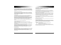
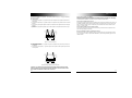
Figure 1: Front Panel Terminals and Controls
1. FILTER MODE SELECT SWITCH (MODE)
"HPF":
Slide switch to this position if the amplifier is used as a mid/tweeter amplifier.
"OFF":
Slide switch to this position if the amplifier is used as a full-range amplifier.
"LPF":
Slide switch to this position if the amplifier is used as a subwoofer amplifier.
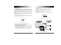
Figure 2: Rear Panel Terminals and Indicators
7. POWER AND PROTECT INDICATOR (PWR/PRT)
Green light indicates that the amplifier is "ON".
Red light indicates either a high current, short circuit or DC offset is detected at the speaker
outputs. The amplifier will revert to normal operation once the problem is rectified.
This indicator also lights up at a high operating temperature. Under this condition, the amplifier will automatically shut down. As soon as the temperature falls to a safe level, the amplifier will automatically resume operation.
2. HIGH-PASS / LOW-PASS FREQUENCY SELECTOR (FREQ)
Select high-pass or low-pass crossover frequency: 80 or 120Hz.
8. POWER INPUT TERMINAL (B+)
To be connected to the positive terminal of the vehicle’s battery or other constant +12 V
source.
3. INPUT SENSITIVITY LEVEL CONTROL (SENS)
The input sensitivity level can be varied from 5.0 volts to 100 mV depending on the output
voltage of the source unit (refer to sub-section titled INPUT SENSITIVITY ADJUSTMENT).
9. GROUND INPUT TERMINAL (GND)
To be wired to the vehicle’s chassis for ground.
4. HIGH IMPEDANCE INPUT (RCA)
To be connected to RCA pre-amp outputs from a source unit (i.e., radio, tape deck or CD
player).
10. REMOTE TURN-ON INPUT TERMINAL (REM)
To be connected to the remote control wire or power antenna lead of the source unit for
remote ON/OFF.
5. LOW IMPEDANCE INPUT (SPKR LEVEL)
To be connected to speaker outputs from a source unit (i.e. radio, tape deck or CD player)
when RCA outputs are not available.
11. FUSE RECEPTACLE
12. LEFT/RIGHT SPEAKER OUTPUT TERMINAL
For connection to the speaker system.
6. LINE LEVEL OUTPUT
This output can be used to connect to another amplifier for system expansion.
Note: This line level output is full range.
4
5
www.coustic.com
SYSTEM CONFIGURATION
By purchasing the 160SE power amplifier, you are already one step closer to experiencing the
purest and most natural sound quality in the automobile environment. To take full advantage of
the potential of this amplifier, before installation, we strongly recommend that you acquaint yourself with all its available features and then spend some time in designing a system most suitable
for you, consider the components you have now and those that you plan on adding or upgrading
in the future.
BUILT-IN ELECTRONIC CROSSOVERS
An electronic crossover has many advantages over passive crossovers - lower cost, simplified
yet more flexible system design, lower distortion and higher gain structure. The 160SE power
amplifier is equipped with built-in 18 dB per octave electronic crossovers that can be configured
for full-range, high-pass or low-pass applications. The line output is designed to provide additional expansion capability to your sound system.
BI-AMPLIFICATION
A bi-amplified system normally consists of an active crossover and two amplifiers. The active
crossover divides the audio frequency spectrum into two ranges: frequencies below the
crossover point are directed to the amplifier driving the subwoofer(s), while all frequencies above
the crossover point are directed to the amplifier driving the mid-range/tweeters.
Because of the versatility of the Coustic amplifiers, you are quite free to build whatever mobile
audio system you want or to plan a long term expansion scheme for your car’s audio system.
For example, with the low impedance input, you can use the amplifier as a full-range amplifier to
upgrade your existing factory sound system to drive the front full-range speakers. Or you can
make a "parallel" connection on the amplifier to run both the front and rear speakers.
The full-range line output can be used to drive an additional amplifier driving the rear full-range
speakers.
You can also configure the amplifier as a mid/tweeter amplifier.
If you need more power, you can bridge the amplifier as a mono subwoofer amplifier.
3 CHANNEL CONFIGURATION
The Multi-Function Circuit enables the amplifier to be configured as a 1-channel, bridged, mono
amplifier driving a single speaker, 2-channel, stereo amplifier driving a pair of speakers, or quasi
3-channel amplifier.
The bridged mono mode is commonly used for subwoofer amplification. The amplifier provides
more power in the bridged mono mode than it does in stereo mode.
With the assistance of passive crossovers and in its quasi 3-channel mode, the amplifier can be
configured as a 2-way amplifier driving a pair of left- and right-channel, full-range mid-tweeters
and a mono woofer. Care must be taken to choose capacitors and inductors of correct value;
otherwise damage could be done to the speakers and/or the amplifier.
For approximate passive crossover components value, please refer to Coustic’s website,
http//:www.coustic.com.
POWER CABLES
Power cables are as important as battery capacity. Use only high quality power cables of gauge
size AWG 8 or bigger for installation.
YOU CAN NEVER HAVE TOO BIG OF A POWER/GROUND WIRE!
CIRCUIT BREAKER/FUSES
It is also advisable to install a circuit breaker/fuse close to the battery. This would effectively
lower the risk of the power cable catching fire should a short circuit occur in the audio system. A
circuit breaker or fuse with 50% of the main batteries amp hour rating is recommended. Going
larger in circuit breaker or fuse value means that you have NO protection.
DO NOT over fuse! Fuses on the amplifier DO NOT protect the amplifier, they protect the car.
SPECIAL PRECAUTIONS & ACCESSORIES
Quality equipment and proper system design and installation are the ingredients for the ultimate
car audio system. With your wise decision to purchase this Coustic amplifier, you are already
one big step closer to realizing your dream. The next step is simple - have an experienced professional Coustic dealer install your audio system. However, if you prefer to install the system
yourself, we have the following commendations for your reference:
Caution: Improper installation will void the product warranty and Coustic is not responsible for
any consequential damage to the amplifier and/or other audio components and/or electrical components of the vehicle.
TERMINALS, LUGS AND CONNECTORS
High current terminals, lugs and/or connectors are also required to ensure a safe and sure electrical connection and conduction.
NEGATIVE GROUNDING SYSTEM
The 160SE power amplifier is designed for use with a 12-Volt negative ground system. Installing
this amplifier in a vehicle with a POSITIVE ground system will result in severe damage to the
amplifier, other audio components and/or the vehicle’s electrical components. If your vehicle happens to run on a positive ground system, please consult your Coustic dealer.
WARNING: These power amplifiers are very powerful. We strongly recommend
installation in the following manner:
(1)
by professional mobile audio installers; and
(2)
incorporating all of the above special precautions and accessories.
Failure to comply with either one or both of the above conditions will render the warranty void
and Coustic is not responsible for any consequential damage to the amplifier, other audio components and/or electrical components of the vehicle.
SPEAKER IMPEDANCE
Although extremely low impedance speaker loads will not damage the amplifier, for stereo mode,
we recommend speaker loads of 2, 4 or 8 ohms; for bridged mono mode 4 or 8 ohms. (Note: In
bridged mono mode, the amplifier sees only half of the speaker impedance.)
NOTE: Remember that we are not defying the laws of Physics! IF you decide to connect ANY
Coustic amplifier into a bridged mono load BELOW 4 ohms, Physics dictates that current draw
doubles! Be ready!
6
7
www.coustic.com
INSTALLATION
Caution: Please follow all the installation recommendations and instructions in this manual.
Installing and/or using the amplifier in methods other than those outlined herein may reduce the
performance capability of the amplifier. Any such installation or usage renders the product warranty void.
LOCATION
Ventilation: The primary deciding factor of amplifier location is heat dissipation. Despite its highly
efficeint heat dissipation design, the amplifier can be crippled by inadequate ventilation.
Prolonged operation at high volumes, combined with inadequate ventilation, may cause the
amplifier to overheat and trigger the automatic shut down circuit until the temperature returns to a
safe level. To ensure adequate ventilation, the ideal location for the amplifier is a spot away from
any heat source, with at least 2 inches of clearance above and around the unit.
WIRING LAYOUT
Once the location of all the components has been determined, plan the best routes for all the
necessary wiring, making sure that the wires are easily accessible without dismounting the various components.
MOUNTING
1. Place the amplifier at the desired location and use it as a template to determine the exact
position of the mounting holes.
2. Mark the mounting holes with a felt pen.
3. Put the amplifier aside.
4. If the mounting surface is carpeted, cut out small circles of the carpet and padding around
the four mounting holes to expose the metal underneath.
5. Use a center punch to ensure drilling the exact position for the screws. DO NOT BEGIN
DRILLING UNTIL YOU HAVE PUT THE AMPLIFIER ASIDE. USING THE AMPLIFIER AS A
DRILLING GUIDE MAY CAUSE IRREPARABLE DAMAGE TO THE AMPLIFIER.
6. Mount the amplifier with the screws provided.
WIRING
Routing audio cables and power cables together would invariably cause radiated engine noise in
your audio system. If possible, run audio cables on one side of your car and power cables on the
other. Never route these wires underneath the vehicle body.
Note: The battery ground should remain DISCONNECTED at all stages of installation.
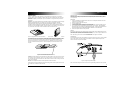
Figure 3: Upright Mount on Horizontal Surface
Figure 4: Parallel Mount on Vertical Surface
The amplifier may be mounted upright on a horizontal surface (see Figure 3) or parallel to a vertical surface (see Figure 4). However, the amplifier should never be mounted upside down (see
Figure 5) for the simple reason that the hot air generated by the amplifier would have to go
through the unit internally on its natural upward path (i.e. "feedback" into the unit) and would
result in increased internal temperature. This would speed up the thermal shut down of the
amplifier.
CONNECTION
Connect the RCA input jacks of the Amplifier to the output of the Source Unit (e.g. radio, cassette
player or CD player). If line level output is not available, connect the speaker outputs of the
source unit to the Loz input of the amplifier.
Figure 5: Inverted Mount (Not Recommended)
Vibration: Constant vibration could eventually cause the amplifier to come off from mount, resulting in stress on wire connections, which, in turn, results in "open" or "short" circuit. For this reason, a location with minimum vibration and a flat surface for secure and firm mounting should be
chosen for the amplifier.
Moisture: The amplifier should also not be exposed to moisture and water.
Taking all the above into consideration, the best mounting position for the amplifier would be the
floor of the trunk or behind the rear seat back.
8
Figure 6: High/Low Impedance Inputs
Note: Connect the black ground wire to the source unit ground only if alternator noise is present.
9
www.coustic.com
Connect the Amplifier to the Speakers. Use thicker speaker wires (e.g. 8 - 10 gauge desirable)
for these connections.
For Stereo Mode
1. Connect the left negative ("–") speaker output of the amplifier to the negative terminal of the
left speaker.
2. Connect the left positive ("+") speaker output of the amplifier to the positive terminal of the left
speaker.
3. Connect the right negative speaker output of the amplifier to the negative terminal of the right
speaker.
4. Connect the right positive speaker output of the amplifier to the positive terminal of the right
speaker.
+
L
-
+
R
Connect the Amplifier to the Battery
Heavy gauge wire is preferred. Add a fuse or circuit breaker to any power wire that runs through
firewall or sheet metal to protect the battery, the vehicle, and more importantly, you. It is highly
recommended that installation is carried out by an authorized Coustic dealer.
Connect the Amplifier Remote Control
Connect the remote input terminal of the amplifier to the remote output terminal of the source unit
to establish amplifier remote on/off through the power on/off of the source unit. If the source unit
does not provide a remote output, connect to its power antenna lead or other switched 12-volt
source, e.g. ignition switch.
Connect the Amplifier Ground to Vehicle Chassis
Find a good ground spot in the vehicle and connect the ground terminal of the amplifier to this
point via a large gauge ground cable.
Reconnect the Battery Ground to the Vehicle Chassis
Double check all the previous installation steps, in particular, the wiring and component connection. If everything is in order, complete the installation by reconnecting the battery ground to the
vehicle chassis.
-
BRIDGE
Figure 7: Stereo Connection
For Bridged Mono Mode
1. Connect the left positive ("+") speaker output of the amplifier to the positive input terminal of
the speaker.
2. Connect the right negative ("–") speaker output of the amplifier to the negative input terminal
of the speaker.
+
L
-
+
R
-
BRIDGE
Figure 8: Bridged Single Woofer Connection
CAUTION: ANY DEVIATION FROM THE ABOVE SPEAKER CONNECTION MAY CAUSE
SERIOUS DAMAGE TO THE AMPLIFIER AND/OR SPEAKERS. PLEASE DOUBLE CHECK
THE CONNECTION BEFORE TURNING THE SYSTEM ON.
10
11
www.coustic.com
FINAL SYSTEM CHECK
INPUT SENSITIVITY ADJUSTMENT
The Input Sensitivity Control is located on the Front Panel. The objective of input sensitivity
adjustment is to match the output of the source unit with the input of the amplifier. The output
voltage of individual source units can vary. For example, some radios have an output of 200 mV,
others have 5 Volts or more. To cater to these variations, the 160SE amplifier has an adjustable
input sensitivity level that ranges from 100 mV to 5 volts.
Adjusting this control requires some experimenting. Basically you want all the gain at the beginning of the system, NOT at the end (amplifier). Turn your headunit volume UP and keep your
amplifier gains at the minimum possible settings. This will give you the best sound and lowest
signal to noise ratio.
CROSSOVER SELECTION
The amplifier has built-in high-pass/low-pass filters that can be defeated by sliding the switch to
the OFF position.
1. When the high-pass is selected, the amplifier will be devoted to mid/tweeters.
2. When the low-pass is selected, the amplifier will be used to drive woofers/subwoofers.
3. When the filter is switched off, the amplifier is used as a full range amplifier.
CROSSOVER FREQUENCY SELECTION
Both the high-pass and the low-pass section offer 2 crossover frequencies - 80 and 120 Hz.
Choose the setting according to your speaker component specification or to your particular
preference.
Besides better sonic reproduction, proper input sensitivity also helps to prolong the reliability
span of your amplifier by eliminating excessive internal temperature generated by incompatible
source unit output and amplifier input.
80Hz - Low-pass selected
Note : Turning the input gain UP does NOT indicate MORE power. Just MORE noise. The input
gain control IS NOT a power control. REMEMBER that the input gain control has nothing to do
with the power output of the amplifier.
OUTPUT
SENS
INPUT
NPUT
S
MODE
MAX
FREQ
HPF OFF LPF
80
120
Figure 10: Crossover Frequency Selection
MODE
180
MIN
5 volts
MAX HPF OFF LPF
30
.1 volt
RCA
outputs
A
OPTION 1 -RCA Outputs
B
CD-328
EJECT
PWR
+
II
MODE
LOUD
MUTE
Battery
LOUD
P.CL
SEL
BAND
–
TUNE
SHUF
RPT
SCAN
EAS
P.ME
P.PLA
1
2
3
4
5
6
ASM
MONO
DISP
WB
DISC
REL
B
CD527 CD/RECEIVER
and CD CHANGER CONTROL
OPTION 2 -Speaker lead Outputs
(Note: You cannot use both RCA and
speaker lead inputs simultaneously!!)
®
–
+
A.S.
RESE
T
TRACK
SEEK
FRONT
speaker lead
outputs
option 2
FRONT speaker
lead Inputs
LoZ
1 D. SCAN
2
SHUFF
LOU
D
3 T.
RPT
DOLBY B
DIS
C
TUNE
70µ
S
TP
S
4 T. SCAN
5 D. RPT
MODE
RX-779
CD Changer Control
Auto Aligned
Azimuth System
P.ME
M
AS
M
6 P. PLAY
PRO
G
SHUFF D.SCAN DISC D.RPT
TRACK
POWER
P.C
L
BAN
D
DIS
P
ME
70µs TPS
AM FM 1 2
3
ST
LOUD
Anybody’s leased car: high power In dash
160SE
POWER AMPLIFIER
(crossover set at 80Hz)
HS-652a
6 1/2 inch Co-Axial
optionFRONT
1 RCA
lead Inputs
HiZ
–
Turn the Input Sensitivity Control all the way down (counter clockwise).
Set the volume control of the source unit to approximately 2/3 of its maximum output.
Turn the balance control of the source unit to its center position.
Leave the tone (bass/treble) controls at their usual position.
Play a CD or tape track with greater dynamic range
To locate the optimum input sensitivity setting, ask the person assisting you to turn the Input
Sensitivity Control clockwise until audio distortion starts to develop. Turn the sensitivity
control backwards slightly to minimize the distortion.
7. If you constantly switch between CD/tape and radio, you will need further adjustment since
radio output level differs from that of CD or tape. In this case, you need to locate a balanced
sensitivity setting which is best for both the output level of radio and that of CD or tape.
+
1.
2.
3.
4.
5.
6.
–
Figure 9: Input Sensitivity Control
+
A
B
Figure 11. Typical System connection
12
13
www.coustic.com
T RO U B L E - S H O OT I N G S E C T I O N
RCA
outputs
A
OPTION 1 -RCA Outputs
B
CD-328
+
SYMPTOM
1 No power
PROBABLE CAUSE
Check connections to the amplifier's Ground, B+ & Remote
terminals. Check connection at "+" terminal of the battery.
Check the remote turn-on terminal. Ensure it receives power
when the source is turned on (or when the switch is turned
on). Refer to the Installation Section. Check the power line
fuse: if fuse is blown, replace it; if fuse continues to blow,
check the power wire and also the amplifier for a short. If the
short is in the power wire, fix it; if the short is in the amplifier
itself, see your Coustic dealer.
Check the voltage at the amplifier, and the remote ON/OFF
lead. The voltage should measure between 11 V-15V. If the
measurement is beyond this range, have the source unit
checked out by an authorized dealer.
2. Power without sound with
red power/protection
indicator on
Turn the amplifier off, and Check all input & output signal
cables and connections. Check the speakers for short with a
VOM or by connecting them to another audio system. After
making sure everything is normal, turn the amplifier on again.
3. Power without sound with
red power indicator on
The continuous red light of the power indicator signals a high
internal operating temperature, which results in the amplifier
switching off temporarily; when the amplifier cools down to a
safe level, the amp will automatically restart.
4. No sound from one side
Check balance control.
Check speaker connections.
Check signal input connection.
5. Very low sound from
both radio & tape
Check your radio's fader control.
Check the amplifier's Input Sensitivity Level.
6. Frequent automatic amplifier
shut down
This indicates that the amplifier is operating at a continually
undesirable high internal temperature.
High operating temperature caused by inadequate ventilation.
(Refer to the sub-section titled LOCATION for better amplifier
location).
High operating temperature caused by an excessively low
impedance load, say below 2 ohms. Check for bad speakers
and/or electronic crossover, proper passive crossover
components; if all else fails, try rewiring the entire system.
High operating temperature can be caused by an incorrect
input sensitivity level (refer to sub-section titled INPUT
SENSITIVITY ADJUSTMENTS for correct setting).
7. "Motorboating": The amplifier
power indicator going off
repeatedly when the audio
system is on.
Check the amplifier's connection to the battery.
Check battery voltage. If low, recharge or replace battery.
Check all ground connections.
EJECT
PWR
II
MODE
LOUD
MUTE
Battery
LOUD
P.CL
SEL
BAND
–
TUNE
SHUF
RPT
SCAN
EAS
P.ME
P.PLA
1
2
3
4
5
6
ASM
MONO
DISP
WB
DISC
REL
B
CD527 CD/RECEIVER
and CD CHANGER CONTROL
OPTION 2 -Speaker lead Outputs
(Note: You cannot use both RCA and
speaker lead inputs simultaneously!!)
®
–
+
A.S.
RESE
T
TRACK
SEEK
1 D. SCAN
FRONT speaker
lead Inputs
LoZ
LOU
D
3 T.
RPT
DOLBY B
PRO
G
DIS
C
TUNE
SHUFF D.SCAN DISC D.RPT
TRACK
70µ
S
TP
S
4 T. SCAN
5 D. RPT
MODE
RX-779
CD Changer Control
Auto Aligned
Azimuth System
P.ME
M
AS
M
6 P. PLAY
POWER
P.C
L
BAN
D
DIS
P
ME
70µs TPS
AM FM 1 2
3
ST
LOUD
Anybody’s leased car: high power In dash
160SE
POWER AMPLIFIER
(crossover set at 80Hz)
+
option 2
SHUFF
–
FRONT
speaker lead
outputs
2
HS-652a
6 1/2 inch Co-Axial
optionFRONT
1 RCA
–
lead Inputs
HiZ
+
A
B
400SE
POWER AMPLIFIER
(crossover set at 80Hz)
–
10RS
10" SUBWOOFERS
+
A
B
Figure 12. Typical multi-amplifier system
14
15
www.coustic.com
SYMPTOM
8. Whining noise when
engine is running with noise
varying with the accelerator
(noise level varies with
source unit volume control).
PROBABLE CAUSE
Reroute power cable from battery to source unit directly,
bypassing the battery terminal in the fuse box.
Check power connections to be sure they are clean.
Check ground connections to be sure the ground wire is in
direct contact with the bare metal surface of the chassis (with
that spot scraped clean of any paint).
9. Constant level whining noise
(most noise with source unit
volume at minimum)
Check for a ground loop in the system. Turn the system off
and one by one change the ground connections
(by changing to a different contact point,scraping the level
constant irrespective of metal clean of any paint, rust or
grease). Turn the system on and check for whining noise after
each ground change.
CAUTION:
Do not disconnect the Power Amplifier's ground when
the system is on. This could damage the amplifier.
Check for defective signal cables. Disconnect signal cables
at the amplifier and listen carefully for noise. If the noise disappears, run a test pair of signal cables. If there is no undesirable whining noise, reconnect to the amplifier with the new
pair of signal cables. Check battery ground connection to the
vehicle chassis to make sure it is tight and clean.
Check battery negative terminal connection to make sure it is
tight and clean.
10. Radiated noise: crackling
noise on FM which is not
present when playing tape
or CD (noise varying slightly
with accelerator, but is
present at all times)
Check if the noise is actually radiated noise: Tune a portable
radio to the same FM station. Move the portable radio close
to the vehicle engine. If crackling noise comes from the
portable radio, then the noise you have in your vehicle audio
system is radiated noise.
Check with a VOM to make sure the antenna is really grounded to the vehicle chassis.
To ensure a true ground, break the plastic covering of the
antenna lead and solder a piece of heavy wire (minimum 14gauge) to the braided shield.
Ground the other end of the wire at the same point as the
radio ground.
Check spark plug wires. They should be suppression-type
wire and less than 2 years old. Otherwise, replace them with
good quality suppression cables.
Make sure engine block is grounded to the vehicle chassis at
a bare metal spot (scraped clean of paint, rust and grease).
SPECIFICATIONS:
160SE
Rated Power @ 14.4 V (0.1 % THD):
4 Ohm Stereo
2 x 40 Watts
Rated Power @ 14.4 V (0.1 % THD):
2 Ohm Stereo
2 x 80 Watts
Rated Power @ 14.4 V (0.2 % THD):
4 Ohm Mono
1 x 160 Watts
Frequency Response:
20 –20,000 Hz +/- 0.5 dB
Input Sensitivity:
0.1 – 5 V
S/N Ratio @ rated power:
100 dB
High-Pass Filter Crossover Frequency:
80 / 120 Hz (18 dB/Oct.)
Low-Pass Filter Crossover Frequency:
80 / 120 Hz (18 dB/Oct.)
Dimensions:
11" W X 2 3/8" X 7 1/4" L (280 X 60 X 185 mm)
Make sure hood is also grounded. If not, use a ground strap
(which is available from any auto parts store) to ground the
hood to the vehicle chassis.
16
17
www.coustic.com
Limited Warranty
Important Notice to Consumer:
Coustic offers the following warranty to the ORIGINAL PURCHASER of COUSTIC
products within the period stated herein:
Coustic warrants all new products against defects in material and workmanship for
a period of ONE (1) YEAR from date of original purchase. The limited warranty is
EXTENDED to TWO (2) YEARS from date of original purchase if the product is
originally installed by an authorized Coustic dealer and is accompanied by a valid
sales receipt showing a charge for installation.
Should a defect occur, Coustic will repair or, at its option, replace defective
units/parts with new or factory rebuilt materials without charge for either parts or
labor to the original purchaser. Replacement units/parts will be warranted for the
remaining portion of the original warranty period.
IMPORTANT: THIS WARRANTY DOES NOT COVER INSTALLATION OR
DAMAGE RESULTING FROM ACCIDENT, MISUSE, ABUSE,
IMPROPER WIRING, INCORRECT VOLTAGE, OPERATING
UNIT AGAINST INSTRUCTIONS IN OWNER’S MANUAL OR
ANY PRODUCT WHICH HAS BEEN OPENED, TAMPERED
WITH OR SERIAL NUMBERS REMOVED.
This warranty does not cover labor costs for removal and/or installation of the unit
for repair. Under no circumstances shall Coustic be liable for any special,
incidental or consequential damages or for any other expenses incurred by reason
of use or sale of this product. This warranty is in lieu of any other warranties
expressed or implied including any implied warranty of merchantability or fitness
for particular use or otherwise.
This warranty gives the CONSUMER specific legal rights and he may also have
other rights which vary from state to state. Some states do not follow the
exclusion or limitation of incidental or consequential damages, hence the above
exclusions and limitations may not apply.
If all fails, call us at 1-602-438-2020, or go to our website at http://www.coustic.com
18
19
7676 S. 46th St.
Suite 2020
Phoenix, AZ 85040
TEL: (602) 438-2020
FAX: (602) 438-7313
A Division of Mitek Corporation Copyright © 2000 • All Rights Reserved
www.coustic.com