1
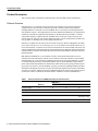
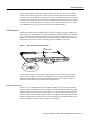
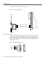
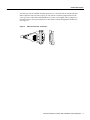
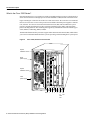
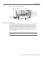
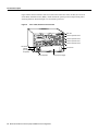
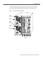
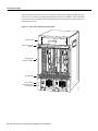
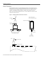
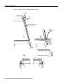
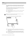
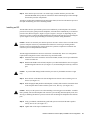
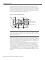
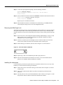
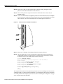
Customer Order Number:
Documentation Part Number:
DOC-781066=
78-1066-04
Ethernet Interface Processor (EIP)
Installation and Configuration
Product Numbers: CX–EIP2, CX-EIP4, and CX–EIP6
This publication provides instructions for installing the Ethernet interface processor (EIP) in your
Cisco 7000 series and Cisco 7500 series router. The upgrade instructions include steps for upgrading
the EIP microcode by downloading a new image. This publication also contains basic configuration
steps and examples for configuring the Ethernet interfaces on a new EIP.
For complete descriptions of interface subcommands and the configuration options available for
Ethernet interfaces, refer to the Router Products Command Reference and Router Products
Command Summary publications, available on UniverCD or in print.
Sections in this publication include the following:
•
•
•
•
•
•
•
Copyright © 1995
Cisco Systems, Inc.
All rights reserved.
Product Description, page 2
Installation Prerequisites, page 13
Installation, page 19
Configuring the Interfaces, page 24
Upgrading Microcode, page 31
Replacing Connector Locks, page 34
Cisco Information Online, page 37
1
Product Description
Product Description
This section provides a description of Ethernet theory and of the EIP features and functions.
Ethernet Overview
The term Ethernet is commonly used for all carrier sense multiple access/collision detection
(CSMA/CD) local area networks (LANs) that generally conform to Ethernet specifications,
including IEEE 802.3. Ethernet Version 2 and IEEE 802.3 were based on, and developed shortly
after, Ethernet Version 1. The slight differences between Ethernet and IEEE 802.3 are implemented
in hardware, and both are supported automatically by the EIP without any hardware or software
configuration changes. Together, Ethernet and IEEE 802.3 are the most widely used local-area
network protocols. They are well suited to applications where a local communication medium must
carry sporadic, occasionally heavy traffic at high peak data rates.
Stations on a CSMA/CD LAN can access the network at any time. Before sending data, the station
listens to the network to see of it is already in use. If it is, the station waits until the network is not
in use, then transmits. A collision occurs when two stations listen for network traffic, hear none, and
transmit simultaneously. When this happens, both transmissions are damaged, and the stations must
retransmit them. The stations detect the collision and use backoff algorithms to determine when they
should retransmit.
Both Ethernet and IEEE 802.3, are broadcast networks, which means that all stations see all
transmissions. Each station must examine received frames to determine whether it is the intended
destination and, if it is, pass the frame to a higher protocol layer for processing. IEEE 802.3 specifies
several different physical layers, and Ethernet defines only one. Each IEEE 802.3 physical layer
protocol has a name that summarizes it characteristics in the format speed/signaling method/segment
length where speed is the LAN speed in Mbps, signaling method is the signaling method used (either
Baseband or Broadband), and segment length is the maximum length between stations in hundreds
of meters. For example, 10Base5 specifies a 10Mbps Baseband LAN with network segments spaced
at 500 meters. Table 1 summarizes the characteristics of Ethernet Version 2 and IEEE 802.3.
Table 1
Ethernet Version 2 and IEEE 802.3 Physical Characteristics
IEEE 802.3
Ethernet
10Base5
10Base2
10BaseT
Data Rate (Mbps)
10
10
10
10
Signaling method
Baseband
Baseband
Baseband
Baseband
Max. segment length (m)
500
500
185
100 (UTP)
Media
50-ohm coax (thick)
50-ohm coax (thick)
50-ohm coax (thin)
Unshielded
twisted pair (UTP)
Topology
Bus
Bus
Bus
Star
2 Ethernet Interface Processor (EIP) Installation and Configuration
Product Description
Ethernet is most similar to IEEE 802.3 10Base5. Both of these protocols specify a bus topology
network with a connecting cable between the end stations and the actual network medium. Both
protocols require a device that acts as an interface between the end stations in this case, the EIP) and
the actual network medium (cable). The Ethernet specifications call this device a transceiver and it
is connected to the station with a transceiver cable. The IEEE 802.3 specifications refers to the same
type of device as a media attachment unit (MAU) and to the cable as an attachment unit interface
(AUI). Both transceiver cables and AUIs can connect to the EIP ports directly.
EIP Description
The Ethernet interface processor (EIP) provides two, four, or six high-speed AUI (10 Mbps) ports;
Figure 1 shows a six-port EIP. Each port supports both Ethernet Version 1 and IEEE 802.3/Ethernet
Version 2 interfaces. A 16-million-instructions-per-second (mips) bit-slice processor provides a
high-speed data path between the EIP and other interface processors. The EIP firmware (microcode),
which contains card-specific software instructions, resides in a ROM in socket U101.
Figure 1
Ethernet Interface Processor (EIP)
0
1
2
3
4
5
En
ab
le
d
Co Tr Re
llis an ce
io sm ive
n
it
H2005
U101,
microcode ROM
You can install interface processors in all available interface processor slots. (Refer to Figure 6,
Figure 7, Figure 8, Figure 9, or Figure 10, depending on your chassis type.) Each Ethernet port
requires an Ethernet transceiver or a media attachment unit (MAU) and a transceiver cable or
attachment unit interface (AUI) to connect to the external network.
Ethernet Interface Ports
The two, four, or six Ethernet connectors on the EIP are standard 15-pin female AUI connectors.
Each port supports both Ethernet Version 1 and IEEE 802.3/Ethernet Version 2 interfaces; the EIP
senses the type of connection from the interface cable you connect and adjusts automatically for the
appropriate interface type. The ports are independent, so you can mix both versions on one EIP.
Slide-type cable locks are standard on all ports; however, an adapter kit is included with each EIP so
that you can change the locks to the jackscrew type to accommodate your interface cables. Refer to
the section “Ethernet Connector Locks” on page 6 for a description.
Ethernet Interface Processor (EIP) Installation and Configuration
3
Product Description
Table 2 lists the signals for the 15-pin Ethernet connector used on the EIP ports.
Table 2
Ethernet Connector Signals
Pin
Circuit
Description
3
DO-A
Data Out Circuit A
10
DO-B
Data Out Circuit B
11
DO-S
Data Out Circuit Shield
5
DI-A
Data In Circuit A
12
DI-B
Data In Circuit B
4
DI-S
Data In Circuit Shield
7
CO-A
Control Out Circuit A (not used)
15
CO-B
Control Out Circuit B (not used)
8
CO-S
Control Out Circuit Shield (not used)
2
CI-A
Control In Circuit A
9
CI-B
Control In Circuit B
1
CI-S
Control In Circuit Shield
6
VC
Voltage Common
13
VP
Voltage Plus
14
VS
Voltage Shield
Shell
PG
Protective Ground/Case Ground
EIP LEDs
The EIP contains the enabled LED that is standard on all interface processors and a bank of status
LEDs for each of the ports. After system initialization, the enabled LED goes on to indicate that the
EIP has been enabled for operation. The following conditions must be met before the EIP is enabled:
•
•
•
The EIP is correctly connected to the backplane and receiving power.
The EIP contains a valid microcode version that has successfully been downloaded.
The CxBus or CyBus recognizes the EIP.
If any of these conditions is not met, or if the initialization fails for other reasons, the enabled LED
does not go on.
Below the enabled LED, a bank of LEDs indicate the state of each physical port. The upper row of
three LEDs indicates the state of port 0, the row below the first indicates port 1, and so on. Each row
of LEDs indicates that the corresponding port is in one of the of three possible states:
•
•
•
Collision—goes on when a frame collision has been detected.
Transmit—goes on when frames are being transmitted.
Receive—goes on when frames are being received.
These LED states are described in more detail the section “Checking the Installation” on page 22.
4 Ethernet Interface Processor (EIP) Installation and Configuration
Product Description
EIP Microcode
The EIP microcode (firmware) is a software image that provides card-specific software instructions.
A ROM component in socket U101 of the EIP module card contains the default EIP microcode. The
router supports downloadable microcode, which enables you to upgrade microcode versions by
downloading new microcode images, storing them in Flash memory, and instructing the system to
load an image from Flash instead of the default ROM image. You can store multiple images for an
interface type and, with a configuration command, instruct the system to load any one of them or the
default ROM image. All interfaces of the same type (EIP, HIP, and so on) will load the same
microcode image, either from the default ROM image or from a single image stored in Flash.
Although multiple microcode versions for a specific interface type can be stored concurrently in
Flash, only one image can load at startup. The show controller cxbus command displays the
currently loaded and running microcode version for each interface processor. The show
configuration EXEC command shows the current system instructions for loading microcode at
startup.
For a complete description of microcode and downloading procedures, refer to the section
“Upgrading Microcode” on page 31.
Ethernet Network Connections
The Ethernet ports on the EIP are standard 15-pin female AUI connectors that require an AUI or
transceiver cable with a 15-pin male connector. (See Figure 2.)
Ethernet AUI Plug and Receptacle
H1447a
Figure 2
You will need an Ethernet transceiver to provide the interface between the EIP ports and the Ethernet
network. Most connections require a transceiver cable between the transceiver and the EIP.
(See Figure 3.) However, some unshielded twisted-pair (10BaseT) transceivers are compact enough
to connect directly to the EIP ports without impeding other connections. When planning your
installation and connections, be sure to consider the high density of ports on the EIP, its proximity
to other interface processors, and the size of any transceivers you plan to connect directly to the
ports. If possible, install the EIP in an interface processor slot between two unoccupied slots to
prevent the transceivers from overlapping the ports on adjacent interface processors.
Ethernet Interface Processor (EIP) Installation and Configuration
5
Product Description
Figure 3 shows an example of a typical Ethernet AUI connection.
Figure 3
Ethernet Cable Connection
To
network
EIP
AUI or transceiver cable
H1353a
MAU or
Ethernet
XCVR
Ethernet Connector Locks
Ethernet ports use either slide-type locks (as shown in Figure 4) or screw-type locks (shown in
Figure 5) to secure the cable to the port and provide strain relief. The slide-type lock is most common
and is used on the EIP ports. The type of connector lock you use on the EIP depends on the type of
Ethernet interface cables you use. Cables with two short posts on the cable connector need the
slide-type lock shown in Figure 4; a bracket on the port slides (or snaps) around the posts on the
cable connector to secure it.
Ethernet Connector Slide Lock
H1447a
Figure 4
6 Ethernet Interface Processor (EIP) Installation and Configuration
Product Description
The slide-type locks are standard on the EIP ports; however, conversion kits are included with each
EIP to replace the slide-type locks on ports you will connect to interface equipment that uses the
screw-type locks. Cables with knurled thumbscrews (screws you can tighten with your fingers) on
the cable connector need a port with jackscrews into which you insert and tighten the thumbscrews.
(See Figure 5.)
Ethernet Connector Jackscrews
H1448a
Figure 5
Ethernet Interface Processor (EIP) Installation and Configuration
7
Product Description
What is the Cisco 7000 Series?
Network interfaces for a Cisco 7000 series reside on modular interface processors, which provide a
direct connection between the high-speed Cisco Extended Bus (CxBus) and the external networks.
Figure 6 and Figure 7 show the rear of the Cisco 7000 series router: the seven-slot Cisco 7000 and
the five-slot Cisco 7010. Access to the processor slots and the removable power supplies is from the
rear, as shown. Two slots are reserved for the Route Processor (RP), which contains the system
processor, and the Switch Processor (SP) (or Silicon Switch Processor [SSP]), which performs
packet switching functions. The remaining slots support any combination of network interface types:
serial, Ethernet, Token Ring, FDDI, or HSSI.
The EIP and all other interface processors support online insertion and removal (OIR), which allows
you to remove and install an EIP while the system is operating, without shutting down system power.
Figure 6
Cisco 7000, Interface Processor End
Captive
installation screw
DC
AC
FA
IL
PO
WE
R
Upper
power supply
I
O
Captive
installation screw
DC
AC
FA
IL
PO
WE
H2358
R
Lower
power supply
I
O
Slot 0
8 Ethernet Interface Processor (EIP) Installation and Configuration
1
2
3
4
SP RP
or
slot
SSP
slot
Product Description
Figure 7
Cisco 7010, Interface Processor End
RP slot
SP or SSP slot
Interface processor slot 2
Interface processor slot 1
Interface processor slot 0
H2359
Power switch
Chassis ground
screw
Power receptacle
DC OK LED
AC-input power supply
What is the Cisco 7500 Series?
The Cisco 7500 series consists of three router models: the Cisco 7505, the Cisco 7507, and the Cisco
7513. All three models provide high reliability, availability, serviceability, and performance. The
three systems support multiprotocol, multimedia routing, and bridging with a wide variety of
protocols and any combination of Ethernet, Fast Ethernet, Token Ring, Fiber Distributed Data
Interface (FDDI), serial, multichannel, channel attachment, and High-Speed Serial Interface (HSSI)
media. Network interfaces reside on modular interface processors, which provide a direct
connection between the high-speed, 1.067-gigabits-per-second (Gbps) Cisco Extended Bus (CyBus)
and the external networks.
Note The Cisco 7507 and Cisco 7513 have dual CyBuses, for an aggregate bandwidth of
2.134 Gpbs.
Ethernet Interface Processor (EIP) Installation and Configuration
9
Product Description
Figure 8 shows the rear of the five-slot Cisco 7505 router. In the Cisco 7505, one slot (4) is reserved
for the Route Switch Processor (RSP1), which contains the system processor and performs packet
switching functions. Slots 0 through 3 are for interface processors.
CO
NS
OL
E
AU
X.
HA
LT
RE
SE
T
CP
U
RSP slot
ROUTE SWITCH PROCESSOR
Interface processor slot 3
EN
AB
LE
EN
AB
LE
SL SLO
OT T
0 1
EJ
EC
T
Cisco 7505, Interface Processor End
NO
RM
AL
Figure 8
Interface processor slot 2
Interface processor slot 1
Interface processor slot 0
H2761
ower switch
Chassis
grounding
receptacles
Power receptacle
10 Ethernet Interface Processor (EIP) Installation and Configuration
AC-input power supply
DC OK LED
Product Description
Figure 9 shows the rear of the seven-slot Cisco 7507 router. In the Cisco 7507, up to two slots (2 and
3) are reserved for the Route Switch Processor (RSP2), which contains the system processor and
performs packet switching functions. Slots 0 and 1, and 4 through 6 are for interface processors.
Figure 9
Cisco 7507, Interface Processor End
Captive
nstallation screw
DC
AC
FA
IL
PO
WE
R
EN
NO
AB
RM
LE
AL
Upper
ower supply
Chassis
grounding
eceptacles
EJ
EC
T
SL SLO
OT T
0 1
I
SL MAS
AV T
E ER
O
SL
AV
E/M
AS
TE
R
Captive
nstallation screw
CP
U
HA
LT
EN
AB
RE
LE
SE
T
DC
AC
FA
IL
PO
WE
H3888
R
Lower
ower supply
AU
X.
NS
OL
E
I
ROUTE SWITCH PROCESSOR 2
CO
O
Slot 0
1
2
3
4
5
6
RSP slots
Ethernet Interface Processor (EIP) Installation and Configuration
11
Product Description
Figure 10 shows the rear of the Cisco 7513, with two AC-input power supplies installed. Two slots
(6 and 7) are reserved for the second generation Route Switch Processor (RSP2), which contains the
system processor and performs packet switching functions. Slots 0 through 5, and 8 through 12 are
for interface processors.
Figure 10
Cisco 7513, Interface Processor End
Blower module
Cable-management
bracket
NO
RM
AL
EN
AB
LE
EJE
CT
SLO SLO
T0 T1
SLA MAS
VE TE
R
Card cage and
processor modules
SLA
VE
/M
AS
TE
R
CP
U
HA
LT
RE
SE
EN
T
AB
LE
AU
X.
ROUTE SWITCH PROCESSOR 2
CO
NS
OLE
Air intake vent
FAN OUTPUT
OK
AC
FAN OUTPUT
OK
OK
FAIL
FAIL
POWER
A
POWER
I
I
0
0
12 Ethernet Interface Processor (EIP) Installation and Configuration
B
H3087
Power supplies
Chassis grounding
receptacle (2)
AC
OK
Installation Prerequisites
Installation Prerequisites
This section provides a list of parts and tools you will need to perform the installation, and safety
and ESD-prevention guidelines to help you to avoid injury and damage to the equipment. It also
provides a detailed description of the online insertion and removal (OIR) function to help you
perform online installation successfully and avoid error message and system restarts. If you are
installing a new EIP, be sure to review the equipment descriptions and distance limitations in the
section “Ethernet Network Connections” on page 5 when preparing your site and planning network
connections.
Distance Limitations for Ethernet Connections
The maximum distances for Ethernet network segments and connections depend on the type of
transmission cable used: 0.4 diameter coax (10Base5), 0.25-inch diameter coax (10Base2), or
unshielded twisted-pair (10BaseT). The term 10Base5 is an abbreviation for 10-Mbps transmission,
Baseband medium, and a maximum cable length of 500 meters.
Network connections to the coax-type cables are tapped into a network segment and must be spaced
at specific intervals. The maximum number of connections (taps) per segment and the recommended
intervals at which they must be placed are shown in Table 3. A maximum of four repeaters can be
used to link segments in a single network.
Table 3
Ethernet Coax-Type Connection Limits for 10-Mbps Transmission
Parameter
10Base5
10Base2
Cable diameter
1 cm (0.4 in)
0.6 cm (0.25 in)
Maximum segment length
1640 ft (500 m)
500 ft (152 m)
Maximum network length (with 4 repeaters)
8200 ft (2500 m)
2500 ft (762 m)
Maximum connections (taps per segment)
100
30
Minimum connection (tap) spacing
8.2 ft (2.5 m)
1.64 ft (0.5 m)
The unshielded twisted-pair (UTP) cabling used with 10BaseT is suitable for voice transmission, but
might incur problems transmitting data at 10-Mbps rates. The IEEE recommendations for the
maximum distance between station (connection) and hub is 328 feet (100 meters) for 10BaseT at
10 Mbps.
Caution Some 10BaseT transceivers can connect directly to the ports on the EIP. When planning
network connections, consider the size and placement of the transceivers you plan to attach directly
to the EIP. The high density of connectors on the interface processors might prevent you from being
able to attach transceivers directly without overlapping and possibly impairing access to connectors
on adjacent interface processors.
Ethernet Interface Processor (EIP) Installation and Configuration
13
Installation Prerequisites
Ethernet Transceivers
You need an Ethernet transceiver or media attachment unit (MAU) to connect the EIP port to the
Ethernet network. Several types of single-port and multiport transceivers are available. The type you
use depends on the type of cabling your Ethernet network uses: thick wire (10Base5), thin wire
(10Base2), or unshielded twisted pair (10BaseT at 10 Mbps). Some examples are shown in
Figure 11. You can connect either Ethernet Version 1 or Version 2/IEEE 802.3 interfaces; the EIP
automatically supports both types.
Figure 11
Examples of Ethernet Transceiver Connections
To EIP
Attaches directly to EIP
port or to the transceiver cable
Transceiver
cable
15-pin AUI connector
15-pin AUI
connector
Ethernet XCVR
RJ-45
connector
UTP cable
BNC connectors to thin-wire or
thick-wire Ethernet network
To 10BaseT
Ethernet network
To EIP
Transceiver cable
15-pin AUI connector
H1292a
Multiport transceiver
14 Ethernet Interface Processor (EIP) Installation and Configuration
Installation Prerequisites
Safety
Following are safety guidelines that you should follow when working with any equipment that
connects to electrical power or telephone wiring.
Electrical Equipment
Follow these basic guidelines when working with any electrical equipment:
•
Before beginning any procedures requiring access to the chassis interior, locate the emergency
power-off switch for the room in which you are working.
•
•
•
•
Disconnect all power and external cables before moving a chassis.
•
Carefully examine your work area for possible hazards such as moist floors, ungrounded power
extension cables, and missing safety grounds.
Do not work alone when potentially hazardous conditions exist.
Never assume that power has been disconnected from a circuit; always check.
Do not perform any action that creates a potential hazard to people or makes the equipment
unsafe.
Telephone Wiring
Use the following guidelines when working with any equipment that is connected to telephone
wiring or to other network cabling:
•
•
Never install telephone wiring during a lightning storm.
•
Never touch uninsulated telephone wires or terminals unless the telephone line has been
disconnected at the network interface.
•
Use caution when installing or modifying telephone lines.
Never install telephone jacks in wet locations unless the jack is specifically designed for wet
locations.
Preventing Electrostatic Discharge (ESD) Damage
Electrostatic discharge (ESD) damage, which can occur when electronic cards or components are
improperly handled, results in complete or intermittent failures. The EIP comprises a printed circuit
board that is fixed in a metal carrier. Electromagnetic interference (EMI) shielding, connectors, and
a handle are integral components of the carrier. Although the metal carrier helps to protect the board
from ESD, use a preventive antistatic strap whenever handling the EIP. Handle the carriers by the
handles and the carrier edges only; never touch the boards or connector pins. Following are
guidelines for preventing ESD damage:
•
Always use an ESD wrist or ankle strap and ensure that it makes good skin contact and connect
the equipment end of the strap to a captive installation screw on an installed power supply.
•
When installing an EIP, use the ejector levers to properly seat the bus connectors in the
backplane, then tighten both captive installation screws. (See Figure 12.) These screws prevent
accidental removal, provide proper grounding for the system, and they help to ensure that the bus
connectors are seated in the backplane.
•
When removing an EIP, use the ejectors to release the bus connectors from the backplane. Use
the handle to pull the EIP out slowly while keeping your other hand underneath the carrier to
guide it straight out of the slot.
Ethernet Interface Processor (EIP) Installation and Configuration
15
Installation Prerequisites
•
Handle carriers by the handles and carrier edges only; avoid touching the board or connectors;
place a removed EIP board-side-up on an antistatic surface or in a static shielding bag. If you plan
to return the component to the factory, immediately place it in a static shielding bag.
•
Avoid contact between the EIP and clothing. The wrist strap only protects the board from ESD
voltages on the body; ESD voltages on clothing can still cause damage.
Caution Periodically check the resistance value of the antistatic strap. The measurement should be
within the range of 1 and 10 megohms.
Online Insertion and Removal—An Overview
Online insertion and removal (OIR) allows you to remove and replace interface processors while the
system is operating; you do not need to notify the software or shut down the system power. This
section describes the mechanical functions of the system components and stresses the importance of
following the correct procedures to avoid unnecessary restarts or card failures. This section is for
background information only. Subsequent sections provide specific procedures for removing and
installing an EIP. All CxBus and CyBus interface processors support OIR
Each processor module contains a bus connector with which it connects to the system backplane.
The bus connector is a set of tiered pins, in three lengths. The pins send specific signals to the system
as they make contact with the backplane. The system assesses the signals it receives and the order
in which it receives them to determine what event is occurring and what task it needs to perform,
such as reinitializing new interfaces or shutting down removed ones. For example, when you insert
an interface processor, the longest pins make contact with the backplane first, and the shortest pins
make contact last. The system recognizes the signals and the sequence in which it receives them. The
system expects to receive signals from the individual pins in this logical sequence, and the ejector
levers help to ensure that the pins mate in this sequence.
When you remove or insert an interface processor, the backplane pins send signals to notify the
system, which then performs as follows:
1 Rapidly scans the backplane for configuration changes and does not reset any interfaces.
2 Initializes all newly inserted interface processors, noting any removed interfaces and placing
them in the administratively shutdown state.
3 Brings all previously configured interfaces on the interface processor back to the state they were
in when they were removed. Any newly inserted interfaces are put in the administratively shut
down state, as if they were present (but unconfigured) at boot time. If a similar interface processor
type has been reinserted into a slot, then its ports are configured and brought online up to the port
count of the original interface processor.
OIR functionality enables you to add, remove, or replace interface processors with the system
online, which provides a method that is seamless to end users on the network, maintains all routing
information, and ensures session preservation.
When you insert a new interface processor, the system runs a diagnostic test on the new interfaces
and compares them to the existing configuration. If this initial diagnostic test fails, the system
remains off line for another 15 seconds while it performs a second set of diagnostic tests to
determine whether or not the interface processor is faulty and if normal system operation is possible.
If the second diagnostic test passes, which indicates that the system is operating normally and the
new interface processor is faulty, the system resumes normal operation but leaves the new interfaces
disabled. If the second diagnostic test fails, the system crashes, which usually indicates that the new
interface processor has created a problem on the bus and should be removed.
16 Ethernet Interface Processor (EIP) Installation and Configuration
Installation Prerequisites
The system brings online only interfaces that match the current configuration and were previously
configured as up; all other interfaces require that you configure them with the configure command.
On interface processors with multiple interfaces, only the interfaces that have already been
configured are brought online. The new interface remains in the administratively shutdown state
until you configure it and bring it online.
Caution While the EIP supports OIR, the system may indicate a hardware failure if you fail to
follow proper procedures.
The function of the ejector levers (see Figure 12) is to align and seat the card connectors in the
backplane. Failure to use the ejectors and insert the interface processor properly can disrupt the order
in which the pins make contact with the backplane.
Follow the EIP installation and removal instructions carefully, and review the following examples of
incorrect insertion practices and results:
•
Using the handle to force the interface processor all the way into the slot can pop the ejectors out
of their springs. If you then try to use the ejectors to seat the interface processor, the first layer of
pins (which are already mated to the backplane) can disconnect and then remate with the
backplane, which the system interprets as a board failure.
•
Using the handle to force or slam the interface processor all the way into the slot can also damage
the pins on the board connectors if they are not aligned properly with the backplane.
•
When using the handle (rather than the ejectors) to seat the interface processor in the backplane,
you may need to pull the interface processor back out and push it in again to align it properly.
Even if the connector pins are not damaged, the pins mating with and disconnecting from the
backplane will cause the system to interpret a board failure. Using the ejectors ensures that the
board connector mates with the backplane in one continuous movement.
•
Using the handle to insert or remove an interface processor, or failing to push the ejectors to the
full 90-degree position, can leave some (not all) of the connector pins mated to the backplane, a
state which will hang the system. Using the ejectors and making sure that they are pushed fully
into position ensures that all three layers of pins are mated with (or free from) the backplane.
It is also important to use the ejector levers when removing an interface processor to ensure that the
board connector pins disconnect from the backplane in the logical sequence expected by the system.
Any processor module that is only partially connected to the backplane can hang the bus.
Ethernet Interface Processor (EIP) Installation and Configuration
17
Installation Prerequisites
Figure 12
Ejector Levers and Captive Installation Screws
Interface processor
card slot
Ejector
lever
Interface processor card
carrier guide (black)
a
b
Captive
installation
screw
H1984
c
18 Ethernet Interface Processor (EIP) Installation and Configuration
Installation
List of Parts and Tools
You need the following tools and parts to install or upgrade an EIP. If you need additional equipment,
contact a customer service representative for ordering information.
•
Ethernet transceiver and, if required, a transceiver cable
OR
Media attachment unit (MAU) and attachment unit interface (AUI) cable (optional)
•
Number 1 Phillips or a 3/16-inch flat-blade screwdriver for the captive installation screws on the
EIP
•
•
ESD-prevention equipment or the disposable grounding wrist strap included with all upgrade kits
If you are replacing the slide locks on the ports with jackscrews, you also need the following:
— 1/8-inch screwdriver and a 3/16-inch nutdriver
— Jackscrew replacement kit for each port (see page 34 for a list of the kit contents)
Installation
The following sections describe the procedures for removing or installing an EIP in the Cisco 7000.
The OIR function allows you to install and remove an EIP without first shutting down the system;
however, you must follow the instructions carefully. Failure to insert the EIP properly can cause
system error messages indicating a board failure. For a complete description of OIR, refer to the
section “Online Insertion and Removal—An Overview” on page 16.
Each unused interface processor slot contains an interface processor filler (which is an interface
processor carrier without an interface board) to keep dust out of the chassis and to maintain proper
air flow through the interface processor compartment. If you are installing a new EIP that is not a
replacement, you must first remove the interface processor filler from an unused slot; proceed to the
section “Removing an Interface Processor Filler” on page 19. If you are replacing an EIP or
upgrading the microcode EPROM on an EIP, proceed to the section “Removing an EIP” on page 20.
Removing an Interface Processor Filler
Select an unused interface processor slot for the new EIP and remove the interface processor filler
as follows:
Step 1 Choose an available slot for the EIP and ensure that there is enough clearance to
accommodate any interface equipment that you will connect directly to the ports (for
example, transceivers that connect directly to the ports overlap equipment on adjacent
interface processors).
Step 1 Use a screwdriver to loosen the captive installation screws on the interface processor filler.
(See Figure 12.)
Step 2 Place your thumbs on both ejectors and simultaneously pull them both outward to release
the EIP from the backplane connector (in the opposite direction from that shown in
Figure 12c).
Step 3 Grasp the handle with one hand and pull the filler straight out of the slot, keeping your other
hand under the carrier to guide it. (See Figure 13.) Keep the carrier parallel to the
backplane.
Step 4 Store the interface processor filler for future use.
To help prevent dust and contaminants from entering the chassis, do not leave the interface processor
slot open. Immediately proceed to the section “Installing an EIP” on page 21.
Ethernet Interface Processor (EIP) Installation and Configuration
19
Installation
Removing an EIP
The EIP supports OIR; therefore, you need not shut down the interface or the system power when
removing an EIP. If you are replacing a failed EIP, remove the existing board first, then replace the
new EIP in the same slot. Figure 13 shows proper handling of an interface processor during
installation.
Figure 13 shows proper handling of an interface processor for installation in the Cisco 7010 and
Cisco 7505 models. The processor slots are oriented horizontally in the Cisco 7010 and Cisco 7505,
and vertically in the Cisco 7000, Cisco 7507, and Cisco 7513.
To remove an EIP, follow these steps:
Step 1 Disconnect the all cables from the EIP ports (if you will only move the EIP to another port,
this step is not necessary).
Step 2 Use a screwdriver to loosen the captive installation screws at both ends of the EIP.
(See Figure 12.)
Caution Always use the ejector levers to remove or install the EIP. Failure to do so can cause
erroneous system error messages indicating a board failure.
Handling an Interface Processor During Installation and Removal
H1985
Figure 13
Captive installation
screws
Step 3 Place your thumbs on the ejector levers and simultaneously pull both of the ejectors
outward (in the opposite direction from that show in Figure 12c) to release the EIP from the
backplane connector.
Step 4 Use the handle to carefully pull the EIP straight out of the slot, keeping your other hand
under the carrier to guide it. (See Figure 13.) Keep the EIP parallel to the backplane.
Step 5 Place the removed EIP on an antistatic mat or foam pad, or place it in an antistatic bag if
you will return it to the factory.
20 Ethernet Interface Processor (EIP) Installation and Configuration
Installation
Step 6 If the interface processor slot is to remain empty, install an interface processor filler
(MAS7K-BLANK) to keep dust out of the chassis and to maintain proper air flow through
the interface processor compartment.
To help prevent dust and contaminants from entering the chassis, do not leave the interface processor
slot open. Immediately proceed to “Installing an EIP.”
Installing an EIP
The EIP slides into the open interface processor slot and directly to the backplane. The interface
processors are keyed to guide pins on the backplane, so the EIP can be installed only in an interface
processor slot. (Refer to Figure 6, Figure 7, Figure 8, Figure 9, or Figure 10, depending on your
chassis type.) Figure 12 shows the functional details of inserting an interface processor and using the
ejectors. Figure 13 shows proper handling of an interface processor during installation.
Caution Remove or insert only one interface processor at a time. Allow at least 15 seconds for the
system to complete its discovery and initialization tasks before removing or inserting another
interface processor. Disrupting the sequence before the system has completed it verification can
cause the system to interpret hardware failures.
The EIP supports both Ethernet Version 1 and Version 2 automatically. There is no configuration
required when using both versions. Follow these steps to install an EIP:
Step 1 Ensure that the console terminal is connected to the RP (or RSP) Console port and that the
console is turned ON.
Step 2 Hold the EIP handle with one hand, and place your other hand under the carrier to support
the EIP and guide it into the slot. (See Figure 12.) Avoid touching the card or any connector
pins.
Caution To prevent ESD damage, handle interface processors by the handles and carrier edges
only.
Step 3 Place the back of the EIP in the slot and align the notch on the carrier with the groove in
the slot. (See Figure 12.)
Step 4 While keeping the EIP parallel to the backplane, carefully slide it into the slot until the back
of the faceplate makes contact with the ejector levers, then stop. (See Figure 12b.)
Caution Always use the ejector levers when installing or removing processor modules. A module
that is partially seated in the backplane will cause the system to hang and subsequently crash, and
shoving or slamming the interface processor into the slot can damage the backplane and connector
pins.
Step 5 Using your thumbs, simultaneously push both ejectors inward until the EIP is pushed
entirely into its slot. (See Figure 12c.)
Step 6 Tighten both of the captive installation screws.
Ethernet Interface Processor (EIP) Installation and Configuration
21
Installation
Step 7 If you are using cables with slide-type locks, proceed to the next step. If you are using
cables with screw-type locks, follow the instructions in the section “Replacing Connector
Locks” on page 34, before proceeding. When the slide locks are replaced, proceed to the
following step.
Step 8 While referring to Figure 3, which shows a typical Ethernet network connection, connect
each EIP port to your Ethernet network as follows:
•
If using unshielded twisted pair (UTP), attach the UTP network segment cable directly
to the port on the network side of the transceiver. Connect the 10BaseT transceiver
directly to the EIP port, or use a transceiver cable to connect them.
•
For 15-pin Ethernet connectors, attach an Ethernet transceiver cable or AUI an EIP port
and a transceiver or MAU; or, if you are using a transceiver that does not require a cable,
connect the transceiver directly to the EIP connector.
Make sure the connecting cable, if any, is an IEEE 802.3 cable if connecting to an IEEE
802.3 transceiver, or an Ethernet compatible cable if connecting to an Ethernet Version 1
or 2 transceiver.
The EIP automatically supports both Ethernet Version 1 and Version 2. It detects the type of interface
when you connect the cable; there is no configuration required.
Proceed to the next section to check the installation.
Checking the Installation
After you install the EIP, verify the installation by observing the LED states and the console display.
When the system has reinitialized all interfaces, the enabled LED on the EIP and on all interface
processors should go on. The console screen will also display a message as the system discovers
each interface during its reinitialization.
When you remove and replace interface processors, the system provides status messages on the
console screen. The messages are for information only. The following sample display shows the
events logged by the system as an EIP was removed from slot 1; the system then reinitialized the
remaining interface processors and marked as down the Ethernet interfaces on the EIP that was
removed from slot 2. When a new EIP was reinserted, the system automatically brought up the
interfaces that were up when the EIP was removed.
Router#
%OIR-6-REMCARD: Card removed from slot 1, interfaces disabled
%LINK-5-CHANGED: Interface Ethernet2/0, changed state to administratively down
%LINK-5-CHANGED: Interface Ethernet2/1, changed state to administratively down
%LINK-5-CHANGED: Interface Ethernet2/2, changed state to administratively down
%LINK-5-CHANGED: Interface sEthernet2/3, changed state to administratively down
Router#
%OIR-6-INSCARD: Card inserted in slot 1, interfaces administratively shut down
%LINK-5-CHANGED: Interface Ethernet2/0, changed state to up
%LINK-5-CHANGED: Interface Ethernet2/1, changed state to up
%LINK-5-CHANGED: Interface Ethernet2/1, changed state to up
%LINK-5-CHANGED: Interface Ethernet2/3, changed state to up
22 Ethernet Interface Processor (EIP) Installation and Configuration
Installation
When a new EIP is inserted or when an EIP is moved to a new slot, the system recognizes the new
Ethernet interfaces but leaves them in a down state until you configure them and change their state
to up with the configure command. The following example display shows the events logged by the
system as a new EIP is inserted in slot 3:
Router#
%OIR-6-INSCARD: Card inserted in slot 3, interfaces administratively shut
%LINK-5-CHANGED: Interface Ethernet3/0, changed state to administratively
%LINK-5-CHANGED: Interface Ethernet3/1, changed state to administratively
%LINK-5-CHANGED: Interface Ethernet3/2, changed state to administratively
%LINK-5-CHANGED: Interface Ethernet3/3, changed state to administratively
down
down
down
down
down
Verify that the EIP is installed correctly as follows:
Step 1 While the system reinitializes each interface, observe the console display messages and
verify that the system discovers the EIP as follows:
•
If you installed a new EIP, the system should recognize all new Ethernet interfaces but
leave them configured as down.
•
If you replaced an EIP, the system should recognize each interface and place it in the
same state (up or down) each was in when you removed the EIP.
Step 2 When the reinitialization is complete, verify that the enabled LED on the EIP goes on and
remains on. If it does, proceed to step 5. If it does not, proceed to the next step.
Step 3 If the enabled LED on the EIP fails to go on, suspect that the EIP board connector is not
fully seated in the backplane. Loosen the captive installation screws, then firmly push both
ejectors into place until they are approximately in the same orientation as the EIP faceplate.
Tighten the captive installation screws. After the system reinitializes the interfaces, the
enabled LED on the EIP should go on. If it does, proceed to step 5. If it does not, proceed
to the next step.
Step 4 If the enabled LED still fails to go on, remove the EIP and try installing it in another
available interface processor slot.
•
If the enabled LED goes on when the EIP is installed in the new slot, suspect a failed
backplane port in the original interface processor slot.
•
If the enabled LED still fails to go on, but other LEDs on the EIP go on to indicate
activity, proceed to step 5 to resume the installation checkout and suspect that the
enabled LED on the EIP has failed.
•
•
If no LEDs on the EIP go on, suspect that the EIP is faulty.
If the enabled LED still does not go on, do not proceed with the installation. Contact a
customer service representative to report the problem and obtain further instructions.
Instructions for obtaining technical assistance are provided at the end of this
publication.
Step 5 If the EIP is new and not a replacement, proceed to the section “Configuring the Interfaces”
on page 24 to configure the new interfaces. (This does not have to be done immediately, but
new interfaces will not be available until you configure them.)
Step 6 If this installation was a replacement EIP, use the show interfaces or show controllers
cxbus command to verify the status of the interfaces. (Refer to the section “Command
Descriptions and Examples” on page 29.) If you replaced an EIP with a new EIP with a
greater number of ports (for example, if you replaced a four-port EIP with a six-port EIP),
the system will recognize the first four interfaces but will not recognize the two new
additional interfaces. The two new interfaces will remain in the down state until you
configure them.
Ethernet Interface Processor (EIP) Installation and Configuration
23
Configuring the Interfaces
Step 7 When the interfaces are up, check the activity of each interface by observing the Ethernet
interface status LEDs, which are described in the section “EIP LEDs” on page 4.
If an error message is displayed on the console terminal, refer to the System Error Messages
publication for error message definitions. If you experience other problems that you are unable to
solve, contact a service representative for assistance.
This completes the EIP installation. If you installed a new EIP or if you installed a replacement EIP
with a greater number of ports than the original, you must now configure the new interfaces as
described in the following section.
TR
AN REC
E
S
ON MIT IVE
LEDs on the EIP, Horizontal Orientation
H2063
5
4
2
3
1
0
CO
LL
EN
ISI
AB
LE
D
Figure 14
Configuring the Interfaces
If you installed a new EIP or if you want to change the configuration of an existing interface, you
must enter the configuration mode. If you replaced an EIP that was previously configured, the system
will recognize the new EIP interfaces and bring each of them up in their existing configuration.
After you verify that the new EIP is installed correctly (the enabled LED goes on), use the privileged
level configure command to configure the new interfaces. Be prepared with the information you will
need, such as the following:
•
•
•
Protocols you plan to route on each new interface.
Internet protocol (IP) addresses if you are configuring the interfaces for IP routing.
Whether the new interfaces will use bridging.
Refer to the Router Products Configuration Guide for a summary of the configuration options
available and instructions for configuring Ethernet interfaces.
Note The configure command requires privileged-level access to the EXEC command interpreter,
which usually requires a password. Contact your system administrator, if necessary, to obtain
exec-level access.
24 Ethernet Interface Processor (EIP) Installation and Configuration
Configuring the Interfaces
Using the EXEC Command Interpreter
Before you use the configure command, you must enter the privileged level of the EXEC command
interpreter with the enable command. The system will prompt you for a password if one has been
set.
The system prompt for the privileged level ends with a pound sign (#) instead of an angle bracket
(>). At the console terminal, enter the privileged level as follows:
Step 1 At the user-level EXEC prompt, enter the enable command. The EXEC prompts you for a
privileged-level password, as follows:
Router> enable
Password:
Step 2 Enter the password (the password is case sensitive). For security purposes, the password is
not displayed.
Step 3 When you enter the correct password, the system displays the privileged-mode system
prompt (#) as follows:
Router#
Proceed to the following section to configure the new interfaces.
Using the Configure Command
Following are instructions for a basic configuration: enabling an interface and specifying IP routing
on an Ethernet interface. You might also need to enter other configuration subcommands, depending
upon the requirements for your system configuration and the protocols you plan to route on the
interface. For complete descriptions of configuration subcommands and the configuration options
available for Ethernet interfaces, refer to the Cisco 7000 Addendum to the Router Products
Configuration and Reference and the Router Products Configuration and Reference publications.
In the router, physical port addresses specify the actual physical location of each interface port on
the router interface processor end. (See Figure 15.) The address is composed of a two-part number
in the format slot/port number. The first number identifies the slot in which the interface processor
is installed (0 through 2, beginning at the bottom slot, as shown in Figure 15). The second number
identifies the physical port number on the interface processor. The ports on each interface processor
are numbered sequentially from left to right beginning with the port 0.
Ethernet Interface Processor (EIP) Installation and Configuration
25
Configuring the Interfaces
Interface ports maintain the same address regardless of whether other interface processors are
installed or removed. However, when you move an interface processor to a different slot, the first
number in the address changes to reflect the new slot number. For example, on a six-port EIP in slot
1, the address of the first port (on the left) is 1/0 and that of the right-most port is 1/5. If you remove
the EIP from slot 1 and install it in slot 2, the addresses of those same ports become 2/0 and 2/5.
Figure 15 shows some of the port numbers of a sample system.
Figure 15
Interface Port Address Examples
1/0
2/0
RP slot
SP slot
Interface processor slot 2
Interface processor slot 1
H2041
Interface processor slot 0
0/2
0/5
Note Although the processor slots in the Cisco 7000, Cisco 7507, and Cisco 7513 are vertically
oriented, and those in the Cisco 7010 and Cisco 7505 are horizontally oriented, all models use the
same slot and port addressing method. (See Figure 6, Figure 7, Figure 8, Figure 9, or Figure 10,
depending on your chassis type.)
Interface slots are numbered 0 to 2 from the bottom slot up (in the orientation shown in Figure 15).
The port numbers always begin at 0 and are numbered from left to right. The number of additional
ports (1, 2, and so on) depends on the number of ports available on an interface. FDDI interfaces are
always n/0, because each FIP supports one interface. Ethernet interfaces can be numbered from 0
through 5 because EIPs support up to six Ethernet ports.
You can identify interface ports by physically checking the slot/port location on the back of the
router or by using software commands to display information about a specific interface or all
interfaces in the router. To display information about every interface, use the show interfaces
command (interfaces is plural) without variables. To display information about a specific interface,
use the show interface command (interface is singular) with the interface type and port address in
the format show interface [type slot/port]. If you abbreviate the command (sho int) and do not
include variables, the system interprets the command as show interfaces and displays the status of
all interfaces.
26 Ethernet Interface Processor (EIP) Installation and Configuration
Configuring the Interfaces
Following is an example of how the show interfaces command, used without variables, displays
status information (including the physical slot and port address) for each interface in the router. In
the following example, most of the status information for each interface is omitted.
Router# show int
Serial0/0 is up, line protocol is up
Hardware is cxBus Serial
Internet address is 131.108.123.4, subnet mask is 255.255.255.0
(display text omitted)
Ethernet1/2 is up, line protocol is up
Hardware is cxBus Ethernet, address is 0000.0c02.d0f1 (bia 0000.0c02.d0f1)
(display text omitted)
Fddi2/0 is administratively down, line protocol is down
Hardware is cxBus Fddi, address is 0000.0c02.adc2 (bia 0000.0c02.adc2)
Internet address is 131.108.31.4, subnet mask is 255.255.255.0
(display text omitted)
You can also use variables such as the interface type (Ethernet, Token Ring, FDDI, serial, or HSSI)
and the port address (slot/port) to display information about a specific interface only. The following
example shows the display for the first Ethernet port on an EIP in slot 1:
Router# show int ether 4/0
Ethernet1/0 is up, line protocol is up
Hardware is cxBus Ethernet, address is 0000.0c02.d0ce (bia 0000.0c02.d0ce)
Internet address is 131.108.31.7, subnet mask is 255.255.255.0
MTU 1500 bytes, BW 10000 Kbit, DLY 1000 usec, rely 255/255, load 1/255
Encapsulation ARPA, loopback not set, keepalive set (10 sec)
(display text omitted)
For complete command descriptions and instructions, refer to the related software documentation.
Note If you install an EIP with six ports in slot 0, you configure the ports in the following format:
0/1, 0/2, 0/3, 0/4, 0/5, and 0/6. If you install an EIP with four ports, you configure the ports in the
following format: 0/1, 0/2, 0/3, 0/4.
Ethernet Interface Processor (EIP) Installation and Configuration
27
Configuring the Interfaces
The following steps describe a basic configuration. Press the Return key after each configuration step
unless otherwise noted.
Step 1 At the privileged-level prompt, enter the configuration mode and specify that the console
terminal will be the source of the configuration subcommands as follows:
Router# configure terminal
Enter configuration commands, one per line.
Router(config)#
End with CNTL/Z.
Step 2 At the prompt, specify the first interface to configure by entering the subcommand
interface, followed by the type (ethernet) and slot/port (interface processor slot number
0). The example that follows is for the first port on an EIP in interface processor slot 1 (see
Figure 15):
Router(config)# interface ethernet 1/0
Step 3 If IP routing is enabled on the system, you can assign an IP address and subnet mask to the
interface with the ip address configuration subcommand as in the following example:
Router(config-int)# ip address 145.22.4.67 255.255.255.0
Step 4 Add any additional configuration subcommands required to enable routing protocols and
adjust the interface characteristics.
Step 5 Change the shutdown state to up and enable the interface as follows:
Router(config-int)# no shutdown
Step 6 Repeat steps 2 through 4 for each new interface.
Step 7 When you have included all of the configuration subcommands to complete the
configuration, press Ctrl-z (hold down the Control key while you press z) to exit the
configuration mode.
Router(config-int)# ^Z
Step 8 Write the new configuration to memory as follows:
Router# copy running-config startup-config
[OK]
Router#
Step 9 Exit the privileged level and return to the user level by entering disable at the prompt as
follows:
Router# disable
Proceed to the following section to check the interface configuration with show commands.
28 Ethernet Interface Processor (EIP) Installation and Configuration
Configuring the Interfaces
Checking the Configuration
After configuring the new interface, use the show commands to display the status of the new
interface or all interfaces.
Command Descriptions and Examples
Following are descriptions and examples of the show commands. Descriptions are limited to fields
that are relevant for verifying the configuration.
•
The show version command displays the configuration of the system hardware (the number of
each interface processor type installed), the software version, the names and sources of
configuration files, and the boot images.
Router> show version
GS Software (GS7), Version 9.17(3)
Copyright (c) 1986-1993 by cisco Systems, Inc.
Compiled Mon 11-Jan-93 14:44
System Bootstrap, Version 4.6(1)
Current date and time is Fri 2-26-1993 2:18:52
Boot date and time is Fri 1-29-1993 11:42:38
Router uptime is 3 weeks, 6 days, 14 hours, 36 minutes
System restarted by power-on
Running default software
Network configuration file is "Router", booted via tftp from 131.108.2.333
RP1 (68040) processor with 16384K bytes of memory.
X.25 software, Version 2.0.
Bridging software.
1 Switch Processor.
1 EIP controller (6 Ethernet).
1 TRIP controller (4 Token Ring).
6 Ethernet/IEEE 802.3 interface.
4 Token Ring/IEEE 802.5 interface.
1 HSSI network interface.
1 FDDI network interface.
128K bytes of non-volatile configuration memory.
4096K bytes of flash memory on embedded flash (in RP1).
Configuration register is 0x0
•
The show interfaces ethernet slot/port command displays statistics for the specific Ethernet
interface you specify by its slot/port address. If you use this command without the type and
slot/port arguments, the system will display statistics for all interfaces in the system.
Router> show int eth 4/1
Ethernet4/1 is administratively down, line protocol is down
Hardware is cxBus Ethernet, address is 0000.0c02.d0cd (bia 0000.0c02.d0cd)
MTU 1500 bytes, BW 10000 Kbit, DLY 1000 usec, rely 255/255, load 1/255
Encapsulation ARPA, loopback not set, keepalive set (10 sec)
ARP type: ARPA, ARP Timeout 4:00:00
Last input never, output never, output hang never
Last clearing of "show interface" counters never
Output queue 0/40, 0 drops; input queue 0/75, 0 drops
Five minute input rate 0 bits/sec, 0 packets/sec
Five minute output rate 0 bits/sec, 0 packets/sec
0 output errors, 0 collisions, 1 interface resets, 0 restarts
(display text omitted)
Ethernet Interface Processor (EIP) Installation and Configuration
29
Configuring the Interfaces
•
The show controllers cxbus command displays the internal status of each interface processor,
including the interface processor slot location, the card hardware version, and the
currently-running microcode version. It also lists each interface (port) on each interface
processor including the logical interface number, interface type, physical (slot/port) address, and
hardware (station address) of each interface. This example shows an EIP installed in interface
processor slot 4:
Router> show controller cbus
Switch Processor 5, hardware version 11.1, microcode version 1.2
512 Kbytes of main memory, 128 Kbytes cache memory
86 1520 byte buffers, 82 4484 byte buffers, 684 byte system buffer
Restarts: 0 line down, 0 hung output, 0 controller error
EIP 4, hardware version 5.1, microcode version 1.0
Interface 32 - Ethernet4/0, station addr 0000.0c02.d0cc (bia 0000.0c02.d0cc)
18 buffer RX queue threshold, 25 buffer TX queue limit, buffer size 1520
ift 0000, rql 18, tq 0000 0000, tql 25
Transmitter delay is 0 microseconds
Interface 33 - Ethernet4/1, station addr 0000.0c02.d0cd (bia 0000.0c02.d0cd)
18 buffer RX queue threshold, 25 buffer TX queue limit, buffer size 1520
ift 0000, rql 18, tq 0000 0000, tql 25
Transmitter delay is 0 microseconds
Interface 34 - Ethernet4/2, station addr 0000.0c02.d0ce (bia 0000.0c02.d0ce)
18 buffer RX queue threshold, 25 buffer TX queue limit, buffer size 1520
Transmitter delay is 0 microseconds
(display text omitted)
•
The show configuration command displays the contents of the system configuration file stored
in NVRAM. This file should reflect all new configuration changes you made and wrote to
memory with the write terminal command.
Router# show config
Using 1652 out of 130048 bytes
version 9.17
!
hostname Router
!
enable-password guessagain
!
microcode TRIP flash trip1-0
microcode reload
!
(display text omitted)
interface Ethernet4/0
ip address 131.108.216.14 255.255.255.0
ip route-cache cbus
!
interface Ethernet4/1
no ip address
shutdown
!
(display text omitted)
•
The show protocols command displays the global (system-wide) and interface-specific status of
any configured Level 3 protocol.
Router> show protocols
Global values:
Internet Protocol routing is enabled
Ethernet1/0 is up, line protocol is up
(display text omitted)
30 Ethernet Interface Processor (EIP) Installation and Configuration
Upgrading Microcode
Using Show Commands to Verify the EIP Status
The following summary describes how to use the show commands to verify that the new interfaces
are configured correctly:
Step 1 Use the show version command to display the system hardware configuration. Ensure that
the list includes the new Ethernet interfaces.
Step 2 Display all the current interface processors and their interfaces with the show controllers
cxbus command. Verify that the new EIP appears in the correct slot.
Step 3 Specify one of the new Ethernet interfaces with the show interfaces ethernet slot/port
command and verify that the first line of the display specifies the interface with the correct
slot number. Also verify that the interface and line protocol are in the correct state: up or
down.
Step 4 Display the protocols configured for the entire system and specific interfaces with the
command show protocols. If necessary, return to the configuration mode to add or remove
protocol routing on the system or specific interfaces.
Step 5 Display the entire system configuration file with the show configuration command. Verify
that the configuration is accurate for the system and each interface.
If the interface is down and you configured it as up, or if the displays indicate that the hardware is
not functioning properly, ensure that the network interface is properly connected and terminated. If
you still have problems bringing the interface up, contact a customer service representative for
assistance.
This completes the configuration procedure for the new Ethernet interfaces.
Upgrading Microcode
The Cisco 7000 series and Cisco 75000 series routers support downloadable microcode, which
enables you to upgrade microcode versions without having to physically replace the EPROMs on the
boards. You can download new microcode versions and store multiple versions in Flash memory,
and you can boot from them just as you can with the system software images. System software
upgrades may also contain upgraded microcode images, which will load automatically when the new
software image is loaded.
This section describes how to use and configure downloadable microcode and, if necessary, how to
replace the microcode EPROM on the EIP.
Downloading Microcode to Flash Memory
You can download microcode to Flash memory by copying the TFTP image of a microcode version
to Flash memory. When the microcode image is stored in Flash memory, you can use the microcode
reload command to manually load the new microcode file, and the configure command to instruct
the system to load the new image automatically at each system boot.
In order to compare the size of the microcode image and the amount of Flash memory available, you
must know the size of the new microcode image. The image size is specified in the README file
that is included on the floppy disk with the new image. Note the size of the new image before
proceeding to ensure that you have sufficient available Flash memory for the new image.
Ethernet Interface Processor (EIP) Installation and Configuration
31
Upgrading Microcode
Caution Before you copy a file to Flash, be sure there is ample space available in Flash memory.
Compare the size of the file you wish to copy to the amount of available Flash memory shown. If the
space available is less than the space required by the file you wish to copy, the copy process will
continue, but the entire file will not be copied into Flash.
Follow these steps to copy a microcode version from the TFTP server to Flash memory.
Step 1 To display the total amount of Flash memory present, its location, any files that currently
exist in Flash memory and their size, and the amount of Flash memory remaining, use the
show flash command. Following is an example of the output that is displayed:
Router# show flash
4096K bytes of flash memory on embedded flash (in RP1).
file
offset
length
0
0xD134
55410
[4085336/4194304 bytes free]
name
sp1-2
Step 2 Compare the amount of available Flash memory (last line in the preceding example) to the
size of the new microcode image on the floppy disk to ensure that there is sufficient space
available. If you attempt to copy in a new image, and the size of the new image exceeds the
available space in Flash, only part of the new image will be copied, and the following error
message will be displayed:
buffer overflow - xxxx/xxxx
where xxxx/xxxx is the number of bytes read in/number of bytes available.
Step 3 After you verify that there is sufficient space available in Flash memory for the new image,
enter the following command at the privileged-level prompt:
Router# copy tftp flash
Step 4 Enter the IP address of the remote host:
IP address or name of remote host [255.255.255.255]? 131.108.12.106
Step 5 Enter the name of the file you want to copy to Flash memory (eip1-1 in the following
example):
Name of file to copy ? eip1-1
Step 6 To confirm that you want the file copied into Flash, press Return.
Copy eip1-1 from 131.108.12.106 into flash memory? [confirm]
OR
If the correct file is not shown, enter no to return to the system prompt and enter the correct
file name.
32 Ethernet Interface Processor (EIP) Installation and Configuration
Upgrading Microcode
Step 7 If you do not want Flash erased, enter no at the next prompt. If you accept the default to
erase by pressing Return without first typing no, the new image will write over the entire
contents of Flash memory and you will lose all other microcode and system software
images stored in Flash.
Erase flash before writing? [confirm] no
While the file is copied to Flash, output similar to the following is displayed:
Loading from 131.108.12.106: !!!!!!!!!!!!!!!!!!!!!!!!!!!!!!!!!!!!!!!!!!!!!!!!!!!!
[OK - 108966/4194304 bytes]
Verifying via checksum...
Flash verification successful. Length = 53364, checksum = 0x0000
Step 8 Use the show flash command to verify that the microcode has been copied to Flash. The
output should display the file name of the image you copied to Flash (eip1-1 in the
following example):
Router# show flash
4096K bytes of flash memory on embedded flash (in RP1).
file
offset
length
name
0
0x40
55410
sp1-2
1
0xD0D4
53364
eip1-1
[4085336/4194304 bytes free]
Step 9 To ensure that the new microcode is used when you reboot the system, add the appropriate
commands to the configuration file. To modify the configuration file, enter the following
command:
Router# configure terminal
Enter configuration commands, one per line.
Router(config)#
End with CNTL/Z.
Step 10 Specify that you are changing the microcode for the EIP (microcode eip), and that it will
load from Flash memory (flash). Then add the file name of the new microcode image to be
loaded from Flash:
Router(config)# microcode eip flash eip1-1
Step 11 To save the configuration file, press Ctrl-Z.
Step 12 Copy the new configuration to NVRAM, as follows:
Router# copy running-config startup-config
[OK]
Router#
The microcode reload command is automatically added to your running configuration.
The new EIP microcode image will load automatically the next time the system boots or
reinitializes.
Step 13 To load the new microcode immediately, you can instruct the system to load the new
microcode by issuing the microcode reload configuration command (you must be in
configuration mode to enter this command):
Router# configure
Enter configuration commands, one per line.
Router(config)# microcode reload
End with CNTL/Z.
Immediately after you enter the microcode reload command and press Return, the system
reloads all microcode. Configuration mode remains enabled; after the reload is complete,
press Ctrl-Z to exit from configuration mode and return to the system prompt.
Ethernet Interface Processor (EIP) Installation and Configuration
33
Replacing Connector Locks
Step 14 To verify that the EIP is using the correct microcode, issue the show configuration or show
controller cxbus command. The show controller cxbus display indicates the currently
loaded and running microcode version for each interface processor.
Router# show configuration
This completes the procedure for downloading microcode to Flash memory.
Replacing Connector Locks
Ethernet connectors have either slide-type or jackscrew-type locks, both of which provide strain
relief and secure the cable to the router port. The slide-type lock is most common, and it is standard
on the EIP ports. If your Ethernet cables use thumbscrews instead of posts, you must replace the
slide-type lock with jackscrews before you can connect the cables to the ports.
List of Required Parts
You need the following tools and parts to complete this replacement procedure. Because the holes
in the EIP are threaded, you need only two lock washers and two jackscrews for each port. You do
not need to install flat washers and hex nuts on the inside of the interface processor faceplate to
secure the jackscrews. Discard the flat washers and hex nuts that are included in the kit.
•
•
1/8-inch screwdriver
Each jackscrew replacement kit includes the following parts:
— Two jackscrews
— Two lockwashers
— Four flat washers (discard)
— Two hex nuts (discard)
Shutting Down Interfaces
If you are replacing the connector locks on an EIP that you have not yet installed in the chassis, skip
this section. If the EIP is already installed in the interface processor slot and the Ethernet interfaces
have been configured, you can avoid potential problems by administratively shutting down the
interfaces and, when the replacement is complete, enabling the interface again. The following steps
provide the commands for shutting down and enabling the interfaces.
The shutdown interface subcommand disables all functions and prevents all packet transmission on
the interface that you specify with the interface type slot/port command. The no shutdown interface
subcommand turns the interface back on. Because interface is a privileged-level configuration
command, you might need a password to enable the privileged level of the EXEC command
interpreter.
Follow these steps to shut down the Ethernet interfaces on the EIP:
Step 1 Follow the steps in the section “Using the EXEC Command Interpreter” on page 25 to
obtain access to the privileged mode of the EXEC.
Step 2 To display the current state of an Ethernet interface, enter the following command:
Router# show interface ethernet slot/port
The status of the interface is displayed. Repeat step 2 for each Ethernet interface and note
the interfaces that need to be shut down.
34 Ethernet Interface Processor (EIP) Installation and Configuration
Replacing Connector Locks
Step 3 At the router privileged-mode prompt, enter the following command:
Router# configure terminal
Enter configuration commands, one per line.
Router(config)#
End with CNTL/Z.
Step 4 Specify an Ethernet interface and enter the shutdown command to shut down the interface:
Router(config)# interface ethernet slot/port
Router(config-int)# shutdown
Repeat step 4 for each Ethernet interface.
Step 5 When all Ethernet interfaces on the EIP have been shut down, press Ctrl-Z (hold the
Control key down and press z) to exit from configuration mode.
Removing the Slide-Type Lock
The bracket for slide-type locks is secured to the EIP port with two small screws. You can complete
this replacement procedure without removing the EIP from the chassis, but you should first shut
down the interfaces you will work on. Following are the steps to remove slide-type locks from EIP
ports:
Step 1 Review the section “Preventing Electrostatic Discharge (ESD) Damage” on page 15 and
make sure that you are wearing a grounding wrist strap that is attached to a captive
installation screw on a power supply.
Step 2 On the first connector port to be changed, use the 1/8-inch screwdriver to loosen and
remove the two small screws that secure the bracket to the connector port.
Step 3 Pull the slide-type lock bracket, which is shown in Figure 16, off the connector.
Connector Slide-Lock Bracket
H1457a
Figure 16
Step 4 Repeat steps 2 and 3 for all additional ports that require jackscrews.
Step 5 Place the removed brackets and slotted screws aside; you can discard them after the
jackscrews are installed, and the installation is complete.
Installing the Jackscrews
Use the hardware provided in the replacement kit to reinstall the connector. Do not use any of the
hardware you removed from the slide-type lock bracket.
Step 1 Ensure that you have removed the slide-type lock bracket, shown in Figure 16, from the
connector port.
Step 2 Insert a lock washer onto the shaft of a jackscrew and push it up to the head of the
jackscrew.
Step 3 Insert the jackscrew into one of the threaded holes on the connector. (See Figure 17.) Turn
the jackscrew clockwise about two full turns to thread it into the hole.
Ethernet Interface Processor (EIP) Installation and Configuration
35
Replacing Connector Locks
Step 4 Repeat steps 2 and 3 for the second jackscrew and lock washer, placing the second
jackscrew in the other threaded hole on the connector.
Step 5 Observe both jackscrews edge-on and turn them another half turn to ensure they are
threaded properly.
Step 6 Use the 3/16-inch nut driver to tighten the jackscrews in the connector. Do not overtighten
the screws; the lock washer will secure the jackscrews in place, and the thumbscrews on the
cable connector, when inserted and tightened, will further tighten the jackscrews.
Figure 17
Jackscrew and Lock Washer Installation
H1458a
EIP
Step 7 Repeat steps 1 through 6 for all additional ports that require jackscrews.
Step 8 This step applies only if you are reinstalling or replacing an EIP and you had already
configured the interfaces: To bring back up any interfaces that you shut down, enter the
privileged level and, at the EXEC prompt, enter the following:
Router# configure terminal
Enter configuration commands, one per line. End with CNTL/Z.
Router(config)#
Router(config)# interface ethernet slot/port
Router(config-int)# no shutdown
Router(config-int)# interface ethernet slot/port
Router(config-int)# no shutdown
Router(config-int)# ^z
Router# copy running-config startup-config
[OK]
Router#
This completes the connector lock replacement procedure. If you are installing a new EIP, return to
“Installing an EIP” to continue with the installation. If you changed the cable locks on an EIP that
was already installed and configured, proceed to the section “Checking the Configuration” on page
29, to verify the status of the interfaces.
36 Ethernet Interface Processor (EIP) Installation and Configuration
Cisco Information Online
Cisco Information Online
Cisco Information Online (CIO) is Cisco Systems’ primary, real-time support channel. Maintenance
customers and partners can self-register on CIO to obtain additional content and services.
Available 24 hours a day, 7 days a week, CIO provides a wealth of standard and value-added services
to Cisco’s customers and business partners. CIO services include product information, software
updates, release notes, technical tips, the Bug Navigator, configuration notes, brochures,
descriptions of service offerings, and download access to public and authorized files.
CIO serves a wide variety of users through two interfaces that are updated and enhanced
simultaneously—a character-based version and a multimedia version that resides on the World Wide
Web (WWW). The character-based CIO (called “CIO Classic”) supports Zmodem, Kermit,
Xmodem, FTP, Internet e-mail, and fax download options, and is excellent for quick access to
information over lower bandwidths. The WWW version of CIO provides richly formatted
documents with photographs, figures, graphics, and video, as well as hyperlinks to related
information.
You can access CIO in the following ways:
•
•
•
WWW:
Telnet:
http://www.cisco.com.
cio.cisco.com.
Modem: From North America, 408 526-8070; from Europe, 33 1 64 46 40 82. Use the
following terminal settings: VT100 emulation; databits: 8; parity: none; stop bits: 1; and baud
rates up to 14.4 kbps.
For a copy of CIO’s Frequently Asked Questions (FAQ), contact
additional information, contact [email protected].
[email protected].
For
Note If you are a network administrator and need personal technical assistance with a Cisco
product that is under warranty or covered by a maintenance contract, contact Cisco’s Technical
Assistance Center (TAC) at 800 553-2447, 408 526-7209, or [email protected]. To obtain general
information about Cisco Systems, Cisco products, or upgrades, contact 800 553-6387,
408 526-7208, or [email protected].
This document is to be used in conjunction with the Cisco 7000 Hardware Installation and Maintenance, Cisco 7010 Hardware Installation and Maintenance, Cisco 7505 Hardware
Installation and Maintenance, Cisco 7507 Hardware Installation and Maintenance, and Cisco 7513 Hardware Installation and Maintenance publications. (1066eip.fm)
Catalyst, CD-PAC, CiscoFusion, Cisco IOS, CiscoPro, CiscoView, CiscoVision, CiscoWorks, ControlStream, DesignDirector, EtherChannel, HubDirector, HubSwitch, LAN2LAN,
LAN2LAN Enterprise, LAN2LAN Remote Office, LAN2PC, Newport Systems Solutions, Packet, PC2LAN/X.25, Point and Click Internetworking, RouteStream, SMARTnet,
SwitchProbe, SynchroniCD, The Cell, TrafficDirector, VirtualStream, VlanDirector, WNIC, Workgroup Director, Workgroup Stack, and XCI are trademarks, Access by Cisco and
Bringing the power of internetworking to everyone are service marks, and Cisco, Cisco Systems, the Cisco Systems logo, EtherSwitch, IGRP, Kalpana, LightStream, and UniverCD are
registered trademarks of Cisco Systems, Inc. All other trademarks, service marks, registered trademarks, or registered service marks mentioned in this document are the property of their
respective owners.
Copyright © 1995, Cisco Systems, Inc.
All rights reserved. Printed in USA
959R
Ethernet Interface Processor (EIP) Installation and Configuration
37