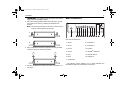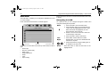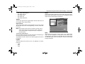
1
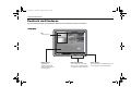
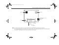
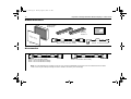
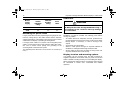
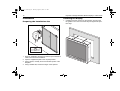
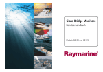
81277_1.book Page 1 Thursday, August 17, 2006 1:51 PM
Raymarine Sunlight
Viewable Marine
Displays
Users Guide
Document Number: 81277_1
Date: August 2006
81277_1.book Page 2 Thursday, August 17, 2006 1:51 PM
Trademarks and registered trademarks
Autohelm, HSB, Raymarine, RayTech, RayTech RNS, Sail Pilot,
SeaTalk and Sportpilot are registered trademarks of Raymarine
Limited. Apelco is a registered trademark of Raymarine Holdings
Limited (Registered in all major marketing territories).
AST, Autoadapt, Auto GST, Autoseastate, Autotrim, Bidata,
Marine Intelligence, Maxiview, On Board, Raychart, Raynav,
Raypilot, Raystar, ST40, ST60, Seaclutter, Smart Route, Tridata
and Waypoint Navigation are trademarks of Raymarine Limited.
All other product names mentioned are trademarks or registered
trademarks (if applicable) of their respective companies.
© Raymarine plc 2006
81277_1.book Page i Thursday, August 17, 2006 1:51 PM
Contents
i
Contents
Safety notices ..................................................
1
TFT LCD technology ........................................
3
Introduction ........................................................................... 3
Installation ............................................................................. 3
Important information .....................................
5
Introduction ........................................................................... 5
EMC conformance ................................................................ 5
Handbook information ........................................................... 5
Waste Electrical and Electronic Equipment Directive ........... 5
Restriction of the use of certain Hazardous Substances ...... 5
Warranty ............................................................................... 6
Controls and features ......................................
7
Typical installation................................................................. 9
Installation .....................................................
11
EMC installation guidelines ................................................. 11
Connections to other equipment...................................... 11
Whats in the box? ............................................................... 12
Accessories......................................................................... 12
Planning the installation ...................................................... 13
Power requirements......................................................... 13
CAUTION ............................................................................ 13
Power connections .......................................................... 13
CAUTION ............................................................................ 13
Extending the power cable .............................................. 14
Cable runs ....................................................................... 14
CAUTION ............................................................................ 14
Display location and mounting options ............................ 14
Mounting options................................................................. 15
IP address label ............................................................... 15
Installation ........................................................................... 16
Preparing the installation site........................................... 16
Installing the display......................................................... 16
Rear connections ............................................................. 17
Operation .......................................................
19
Introduction.......................................................................... 19
Using the buttons ................................................................ 19
Power............................................................................... 19
OSD menu........................................................................... 20
Navigating the OSD ......................................................... 20
Using the OSD .................................................................... 21
Video input ....................................................................... 21
PIP ................................................................................... 21
PIP shortcut ..................................................................... 24
Night mode....................................................................... 25
Image adjustment ............................................................ 25
Set up............................................................................... 27
Color ................................................................................ 28
Input naming .................................................................... 29
Secondary functions ........................................................ 30
Maintenance and troubleshooting ................
31
Maintenance........................................................................ 31
Routine checks ................................................................ 31
Cleaning the display......................................................... 31
Disconnecting the power supply ...................................... 31
Troubleshooting................................................................... 32
Common problems and their solutions ............................ 32
Technical support............................................................. 32
Technical specification .................................
33
Dimensions.......................................................................... 33
General................................................................................ 33
81277_1.book Page ii Thursday, August 17, 2006 1:51 PM
ii
Raymarine Sunlight Viewable Marine Displays - Users Guide
81277_1.book Page 1 Thursday, August 17, 2006 1:51 PM
Safety notices
1
Safety notices
WARNING
WARNING
Product installation
Lightning strikes
This equipment must be installed and operated in
accordance with the Raymarine instructions
provided. Failure to do so could result in poor
product performance, personal injury, and/or
damage to your boat.
To prevent damage caused by lightning or
abnormal current peaks, disconnect the display
from the power source during intense storms, or
when it is not being used for long periods of time.
WARNING
Electrical safety
Make sure you have set the boat’s power supply
to OFF before you start installing this product.
WARNING
High voltage
The display unit contains high voltages. Adjustments require specialized service procedures
and tools only available to qualified service technicians - there are no user serviceable parts or
adjustments.
The operator should never remove the display
unit cover or attempt to service the equipment.
WARNING
Navigation aid
When this product is used within a navigation
system, it is only an aid to navigation. It’s accuracy can be affected by many factors, including
equipment failure or defects, environmental
conditions and improper use or handling. It is the
user’s responsibility to exercise common
prudence and navigational judgements. This
product should not be relied upon as a substitute
for such prudence and judgement. Always maintain a permanent watch so that you can respond
to situations as they develop.
81277_1.book Page 2 Thursday, August 17, 2006 1:51 PM
2
Raymarine Sunlight Viewable Marine Displays - Users Guide
CAUTION
CAUTION
Ultra violet light
Thermal circuit breaker
To provide protection against the damaging
effects of ultra violet (UV) light, the sun cover
should be placed on the unit when not in use.
If you do not have a thermal circuit breaker or
fuse in your power circuit, e.g. fitted to the DC
distribution panel, you MUST fit an in-line breaker
or fuse to the positive (red) lead of the power
cable.
CAUTION
CAUTION
Cleaning
DO NOT use acid, ammonia based or abrasive
products.
CAUTION
Power requirements
This display is not intended for use on boats with
“positive” ground . The power input cable earth
screen connections must be connected directly
to the boats ground.
Cable runs
DO NOT pull the cable through bulkheads using a
cord attached to the connector. this may damage
the connections
81277_1.book Page 3 Thursday, August 17, 2006 1:51 PM
TFT LCD technology
3
TFT LCD technology
Introduction
Your Raymarine sunlight
viewable marine display is
visible in direct sunlight.
The colors of the display
may seem to vary when
viewed against a colored
background or in colored
light. This is a perfectly
normal effect that will be
seen with all color liquid
crystal diplays (LCD’s).
In common with all Thin
Film
Transistor
(TFT)
displays, the screen may
exhibit a few (less than 20)
wrongly illuminated pixels.
These may appear as
black pixels in a light
portion of the screen, or as
colored pixels in black
areas.
Installation
It is important that your new display is installed and operated in
accordance with the instructions provided in this handbook.
Failure to do so could result in poor product performance and
may invalidate your warranty.
When planning the installation the following points must be
considered:
•
Your Raymarine display is sunlight viewable and visible in
direct sunlight. There are, however, limitations to the amount
of heat the display can absorb before developing problems.
• If temperatures exceed the normal temperature operating
range the display could overheat and begin to blackout due
to the limiations of TFT LCD technology.
• In order to minimze the chances of a malfunction, the
following precautions should be taken during installation:
• The display should be installed in an area where there is
proper and adequate ventilation. If it is possible to cool
the area behind the display, it will significantly reduce the
risk of a malfunction.
• The display should be mounted at an angle to the sun.
We do not recommend mounting the unit in a flat plane,
which increases the surface area exposed to the sun and
leads to increased heat absorption.
• The suncover should be used when the display is not in
use.
IMPORTANT: Your Raymarine display is only waterproof from
the front. To maintain watertight integrity the display must be
flush mounted ensuring that the rear casing is enclosed in a
watertight enclosure.
Full details of installation can be found on page 11 in the Installation section.
81277_1.book Page 4 Thursday, August 17, 2006 1:51 PM
4
Raymarine Sunlight Viewable Marine Displays - Users Guide
81277_1.book Page 5 Thursday, August 17, 2006 1:51 PM
Important information
5
Important information
Introduction
The range of Raymarine Sunlight Viewable Marine Displays has
been developed to be used as part of an integrated marine navigation system or within an entertainment system.
The displays, available in several sizes, are designed to be
waterproof and suitable for use above or below decks.
The displays will accept VGA, DVI, Composite Video and SVideo inputs and comply with VESA DDC 1/2B Windows Plug
and play.
This handbook contains important information on the installation,
operation and maintenance of the Raymarine Sunlight Viewable
Marine Display range which is intended for use in the recreational marine market and covers all models.
EMC conformance
All Raymarine equipment and accessories are designed to the
best industry standards for use in the recreational marine environment. The design and manufacture of Raymarine equipment
and accessories conform to the appropriate ElectroMagnetic
Compatibility (EMC) standards, but correct installation is
required to ensure that performance is not compromised.
Handbook information
The technical and graphical information contained in this handbook, to the best of our knowledge, was correct as it went to
press. However, our policy of continuous improvement and
updating may change product specifications without prior notice.
As a result, unavoidable differences between the product and
handbook may occur from time to time. Raymarine cannot
accept responsibility for any inaccuracies or omissions it may
contain. For the latest product information visit our website www.raymarine.com
Waste Electrical and Electronic
Equipment Directive
The Waste Electrical and Electronic Equipment (WEEE)
Directive requires the recycling of waste electrical and
electronic equipment. Whilst the WEEE Directive does
not apply to some of Raymarine’s products, we support
its policy and ask you to be aware of how to dispose of
this product.
The crossed out wheelie bin symbol, illustrated above, and
found on our products signifies that this product should not be
disposed of in general waste or landfill.
Please contact your local dealer, national distributor or Raymarine Technical Services for information on product disposal.
Restriction of the use of certain
Hazardous Substances
RoHS
COMPLIANT
This product uses components that comply with the
requirements of the Restriction of the use of certain
Hazardous Substances (RoHS) Directive 2002/95/
EC.
81277_1.book Page 6 Thursday, August 17, 2006 1:51 PM
6
Raymarine Sunlight Viewable Marine Displays - Users Guide
Warranty
To register your new Raymarine product, please take a few
minutes to fill out the warranty card included in the box or go to:
www.raymarine.com.
It is important that you complete the owner information and
return the card to receive full warranty benefits, including notification of software updates if they are required.
81277_1.book Page 7 Thursday, August 17, 2006 1:51 PM
Controls and features
7
Controls and features
Your Raymarine Sunlight Viewable Marine Display has the following controls and features:
PIP
Picture in picture.
Display screen
High brightness,
sunlight viewable LCD
display with high contrast
text and graphics.
OSD control buttons
Press as required to select video
inputs, access secondary functions,
or navigate through the OSD menu.
Power button
Press and hold to turn the display ON or OFF.
Press to display a list of assigned inputs.
81277_1.book Page 8 Thursday, August 17, 2006 1:51 PM
8
Raymarine Sunlight Viewable Marine Displays - Users Guide
Intake filter
Exhaust fan
SeaTalkhs/Ethernet connection
Selector switch*
Serial port
Power
DVI
connections
VGA
S-Video
Composite video
Notes: 1.* Selector switch enables you to switch between the SeaTalkhs/Ethernet and serial port connections.
2.The SeaTalkhs/Ethernet port will allow a level of OSD controlfrom a compatible Raymarine product, but does not have
full SeaTalkhs compatibility as it will not show video data over the network.
81277_1.book Page 9 Thursday, August 17, 2006 1:51 PM
Controls and features
9
Typical installation
The diagram below shows typical installations using a Raymarine display:
DVI
Input
DVI
Output
VGA
Input
Power IN
from ship's supply
Composite video,
S-video input
VGA
Input
VGA
Output
VGA
Output
S-Video
Output
PAGE
ACTIVE
WPTS
MOB
DATA
MENU
OUT
RANGE
IN
OK
CANCEL
DXXXX-1
81277_1.book Page 10 Thursday, August 17, 2006 1:51 PM
10
Raymarine Sunlight Viewable Marine Displays - Users Guide
81277_1.book Page 11 Thursday, August 17, 2006 1:51 PM
Installation
11
Installation
EMC installation guidelines
•
All Raymarine equipment and accessories are designed to best
industry standards for use in the recreational marine
environment.
Their design and manufacture conforms to the appropriate Electromagnetic Compatibility (EMC) standards, but correct
installation is required to ensure that performance is not compromised. Although every effort has been made to ensure that they
will perform under all conditions, it is important to understand
what factors could affect the operation of the product.
The guidelines given here describe the conditions for optimum
EMC performance, but it is recognized that it may not be
possible to meet all of these conditions in all situations. To
ensure the best possible conditions for EMC performance within
the constraints imposed by any location, always ensure the
maximum separation possible between different items of electrical equipment.
For optimum EMC performance, it is recommended that wherever possible:
•
Raymarine equipment and cables connected to it are:
• At least 3 ft. (1m) from any equipment transmitting, or
cables carrying radio signals, e.g. VHF radios, cables
and antennas. In the case of Single Side Band (SSB)
radios, the distance should be increased to 7 ft. (2m).
• More than 7 ft. (2m) from the path of a radar beam. A
radar beam can normally be assumed to spread 20
degrees above and below the radiating element.
•
•
The equipment is supplied from a separate battery to that
used for engine start. Voltage drops below 10 V, and
starter motor transients, can cause the equipment to
reset. This will not damage the equipment, but may
cause the loss of some information and may change the
operating mode.
Raymarine specified cables are used. Cutting and rejoining
these cables can compromise EMC performance and must
be avoided unless doing so is detailed in the installation
manual.
If a suppression ferrite is attached to a cable, this ferrite
should not be removed. If the ferrite needs to be removed
during installation, it must be reassembled in the same
position.
Connections to other equipment
If your Raymarine equipment is to be connected to other equipment using a cable not supplied by Raymarine, a suppression
ferrite MUST always be attached to the cable near to the
Raymarine unit.
81277_1.book Page 12 Thursday, August 17, 2006 1:51 PM
12
Raymarine Sunlight Viewable Marine Displays - Users Guide
Whats in the box?
Sunlight Viewable
Marine display
Raymarine
Sunlight Viewable
Displays
Users
Guide
RO8176
Mounting
brackets x 2
Suncover
RO8174 - 5 meter VGA cable assembly
Handbook 81277
RO8173 - 1.5 meter Power Cable
Accessories
RO8174 - 5 meter VGA cable assembly
E55055 - 10m E-Series VGA cable assembly*
E55056 - 20m E-Series VGA cable assembly*
E06021 - 5 meter DVI-D cable assembly
Note: *E- Series VGA cables have a waterproof connector at one end and a standard VGA connector at the other. The standard connector should be
used to connect to your monitor, the waterproof connector should be connected to your E-Series display.
81277_1.book Page 13 Thursday, August 17, 2006 1:51 PM
Installation
13
Planning the installation
Grounding the display
Before you install your display, the following points should be
considered:
It is important that an effective radio frequency (RF) ground is
connected to the display. You must ground the display by
connecting the drain wire (shield) of the power input cable to the
nearest ground point of the boat’s RF ground system.
•
•
•
•
Power requirements.
Cable runs.
Display location and mounting options.
Additional accessories, e.g. keyboard or speakers.
Power requirements
CAUTION
Power requirements
This display is not intended for use on boats with
“positive” ground. The power input cable earth
screen connections must be connected directly
to the boats ground.
Your Sunlight Viewable display is designed to run on boat’s DC
power systems rated at 12 V or 24 V. A cable of 1.5 m length is
supplied for connecting the display to your boats DC power
system.
The DC power system should be either:
• Negative grounded, with the negative battery terminal connected
to the boat’s ground, or,
• Floating, with neither battery terminal connected to the boat’s
ground.
Power connections
CAUTION
Thermal circuit breaker
If you do not have a thermal circuit breaker or
fuse in your power circuit, e.g. fitted to the DC
distribution panel, you MUST fit an in-line breaker
or fuse to the positive (red) lead of the power
cable.
The power connection to the display should be made at either
the output of the battery isolator switch, or at a DC power distribution panel. Raymarine recommends that power is fed directly
to the display via its own dedicated cable system and MUST be
protected by a thermal circuit breaker or fuse, fitted close to the
power connection. If you do not have a thermal circuit breaker or
fuse in your power circuit, you MUST fit an in-line breaker or
fuse to the positive (red) lead of the power cable.
Refer to the following table for isolator switch circuit breaker or
fuse value ratings.
Check all terminal connections are clean.
81277_1.book Page 14 Thursday, August 17, 2006 1:51 PM
14
Raymarine Sunlight Viewable Marine Displays - Users Guide
Cable runs
Boat’s
power
supply
Isolator
switch
minimum
rating
Thermal
breaker
rating
Fuse
value
12 V
15 A
8A
12 A
24 V
8A
4A
6A
Extending the power cable
Longer power cable runs may require larger wire gauges to minimize any voltage drop in the cable. Ensure that the minimum
voltage specification of the display is met at the junction of these
cables when the display is operating at full brightness.
If a longer power cable run is required, use the supplied power
cable to connect the free end to the extension cable; take particular care to ensure correct polarity and grounding of the
screening braid to the boat’s RF system.
The supplied power cable has a cross section of 12 AWG (3.3
mm2).
CAUTION
Cable runs
DO NOT pull the cable through bulkheads using a
cord attached to the connector. this may damage
the connections
You need to attach one or more of the cables shown in “Typical
installation” on page 9. Consider the following points before
running any cables:
•
•
•
•
All cables should be adequately secured, protected from
physical damage and exposure to heat. Avoid running cables
through bilges or doorways, or close to moving or hot
objects.
Acute bends must be avoided.
Where a cable passes through an exposed bulkhead or
deckhead, a watertight feed-through should be used.
Secure cables in place using tie-wraps or lacing twine. Coil
any extra cable and tie it out of the way.
Display location and mounting options
Your display can be mounted using the flush mounting kit
supplied. Raymarine recommends that you power the unit and
select a suitable mounting location prior to installing the display.
When planning the display location, the following points should
be considered to ensure safe, comfortable and reliable
operation:
81277_1.book Page 15 Thursday, August 17, 2006 1:51 PM
Installation
•
•
•
•
•
•
•
Convenience- the mounting location should be easily
accessible to allow operation of the controls and should
enable easy viewing of the display.
Installation angle- the display should be mounted at an
angle. Mounting it in a flat plane is not recommended due to
increased heat absorption.
Viewing angle - this LCD has been chosen to give the very
best performance, including viewing angle. However, the
contrast and colors seen on all LCD displays vary slightly
with viewing angle.
Access - there must be sufficient space behind the display
to allow cable connections to the rear connectors, avoiding
tight bends in the cable.
Interference - the selected location should be far enough
away from devices that may cause interference, such as
motors, generators and radio transmitters/receivers.
Magnetic compass - mount the display at least 1 metre (3
ft.) away from a magnetic compass.
Environment - to prevent overheating, do not restrict airflow
at the rear of the display unit; ensure that there is adequate
ventilation, particularly if the display unit is pod-mounted. If
the space behind the display is air conditioned or cooled by a
fan , it will help in keeping the unit’s temperature down when
mounted in direct sunlight.
FAILURE TO ADEQUATELY VENTILATE THE UNIT
COULD INVALIDATE YOUR WARRANTY.
The display should be protected from physical damage and
excessive vibration. Although the display unit is waterproof
from the front when installed correctly, it is good practice to
mount it in a protected area away from prolonged and direct
exposure to rain and salt spray. DO NOT place the display
near to a heat source.
15
Mounting options
Horizontal fixing
Vertical
fixing
Your monitor can be
installed using the
mounting
brackets
(supplied) in either the
horizontal or vertical
keyways.
Make sure that both
brackets are in the
same
orientation
(either both vertical or
both horizontal).
IP address label
You will find a removeable label on your display with an IP
address that will be required to ensure communication with other
Raymarine products.
Before installing your monitor carefully remove this label and
attach it to this handbook or a suitable log book for future
reference.
81277_1.book Page 16 Thursday, August 17, 2006 1:51 PM
16
Raymarine Sunlight Viewable Marine Displays - Users Guide
Installation
Installing the display
Preparing the installation site
1. Carefully insert the monitor into the aperture, ensuring that
the gasket on the rear of the fascia lays flat against the aperture edge.
2
302.2 mm (11.9 in)
15"
LC
D Pa
ne
l te
mpl
ate
Dri
ll
4.1 mount
mm ing
(4 pos
dia hol
itio meter e
ns)
R
sha emov
ded e
onlyareas
3
cente
r lin
e
391
.6 mm
To ensure correct dimensions,
use the template provided.
(15
.4 in)
Ins
tru
me
nt edg
e
Sun
cov
er edg
e
1. Select an installation site that has sufficient space behind for
cable connections and ventilation.
2. Tape the supplied template in the required position.
3. Using a jigsaw, carefully remove the shaded portion of the
template.
4. Using a suitable file, smooth the edges of the aperture.
81277_1.book Page 17 Thursday, August 17, 2006 1:51 PM
Installation
IMPORTANT: The gasket must lay flat against the aperture
edge to ensure watertight integrity.
2. Place the mounting bracket lugs into the keyways (a) and
move them to the rear (b), securing the bracket to the
monitor.
Note: The mounting brackets can be used in either the horizontal or vertical keyways as required.
17
Rear connections
a
1
2
3
4
5
6
7
8
9 10 11 12
13
The rear connectors are:
b
3. Using a suitable screwdriver, tighten the mounting bracket
screws to secure the monitor in position.
1. Power
8. Composite 2
2. VGA 1
9. Composite 3
3. VGA 2
10. S-Video
4. VGA 3
11. SeaTalkhs/ Ethernet
5. DVI 1
12. Selector switch*
6. DVI 2
13. Serial port
7. Composite 1
4. Connect all cables as required - see “Rear connections” on
this page.
* The selector switch enables you to switch between the
SeaTalkhs/ Ethernet and Serial port connections.
81277_1.book Page 18 Thursday, August 17, 2006 1:51 PM
18
Raymarine Sunlight Viewable Marine Displays - Users Guide
81277_1.book Page 19 Thursday, August 17, 2006 1:51 PM
Operation
19
Operation
VGA 1/Menu
VGA 3/Scroll UP
VGA 2/
Scroll DOWN
DVI 2/Scroll RIGHT
DVI 1/Scroll LEFT
Composite Video 2/
Brightness
Composite Video 1/
PIP
Introduction
Your Raymarine Sunlight Viewable display can be controlled
using the On Screen Display (OSD) menu and/or the 10 buttons
on the front bezel of the unit.
The OSD menu enables you to change the way in which your
display is set up and is accessed using the Menu button.
Using the buttons
Each of the 10 buttons on the front bezel of your display has an
input and a control function.
Input functions enable you to select the type of signal input to
the display.
Control functions enable you to change the appearance of the
display.
S-Video/
Enter
POWER
Composite Video 3/
Night mode
Power
Power ON
To power your monitor ON press and hold the
POWER button for 3 seconds.
Power OFF
To power your monitor OFF press and hold the
POWER button for 3 seconds.
Pressing the power button will display a list of what input for the
main screen is associated with each button. This is just a
reminder and is not part of the input selection process.
81277_1.book Page 20 Thursday, August 17, 2006 1:51 PM
20
Raymarine Sunlight Viewable Marine Displays - Users Guide
OSD menu
The OSD menu enables you to change the appearance of your
on-screen display.
Press and hold the Menu button, the OSD appears.
Control tab
Sub menu
Video input.
Picture in Picture (PIP).
Night mode.
Image adjustment.
Setup.
Color.
Input naming.
Navigating the OSD
As a general rule you can navigate through the OSD menu
using the following button presses:
Menu
1. Press and hold to show the OSD menu.
2. Press the Menu button to move between the
7 tabs. Tabs are highlighted from left to right.
When the last tab is highlighted, the next
press will return to the first tab.
3. Press to move to exit a sub-menu and move
to the tab layer of the menu.
4. Press and hold to exit the OSD menu.
Left/
Right
1. Press either of these buttons to switch
between tabs. You can move backwards and
forwards as required.
2. Press these buttons to toggle a sliding bar for
an attribute in the sub-menu.
Down
Press this button to enter the sub-menu of the
highlighted tab.
Control name
There are 7 function tabs across the top of the OSD,from left to
right:
•
•
•
•
•
•
•
Below the tab, the function it controls is named and its sub-menu
is shown.
81277_1.book Page 21 Thursday, August 17, 2006 1:51 PM
Operation
Up/
Down
21
1. Press these buttons to move up or down
within the sub-menu. When you reach the
bottom, pressing the Down button returns to
the top of the sub-menu.
2. After changing an attribute of the sub-menu,
use these buttons to move to the next
attribute.
Using the OSD
•
•
•
2 x DVI inputs.
3 x Composite video inputs.
1 x S-Video input.
PIP
The Picture-in-Picture (PIP) feature of the display enables you to
set up a second input and show the associated image in a
picture inset within the main display screen. The position of this
inset can be moved to suit your personal preference.
Video input
The PIP sub-menu enables you to set up how the PIP appears
on screen and has eleven options:
The Video input sub-menu shows each of the 9 input options
available for the main screen.
The available options are:
•
3 x VGA inputs.
•
•
•
•
•
•
On/Off.
Input source.
Layout.
Size.
Horizontal position.
Vertical position.
81277_1.book Page 22 Thursday, August 17, 2006 1:51 PM
22
•
•
•
•
•
Raymarine Sunlight Viewable Marine Displays - Users Guide
PIP Image White Balance.
PIP Image contrast.
PIP Image Color.
PIP Image Tint.
PIP Image Sharpness.
Child
Selecting this option produces a picture within the main screen.
Both the size and position of the inset can be adjusted and the
aspect ratio of both images is maintained.
On/Off
The left and right buttons toggle between On/Off. When ON, the
PIP appears. OFF, the PIP closes.
Input source
The left and right buttons toggle between all of the 9 inputs
allowed with one source name appearing at a time. Press ENT
to accept.
Note: Some video inputs cannot be viewed in the PIP source
when certain inputs are on the main screen. When this
occurs the message “Unsupported Input” will appear in
the PIP window.
To select an input source:
With the display powered ON, press the button corresponding to
the input source required for the main screen.
The selected source is shown in the bottom right-hand corner of
the display.
Layout
The PIP offers three choices of how it is displayed on screen,
these are:
•
•
•
Child.
Split.
Wide.
Split
Selecting this option splits the main screen in two sections vertically. The PIP enlarges to occupy half of the screen width,
squashing the main screen into the other half. This option does
not maintain aspect ratios and therefore results in both images
looking ‘squashed’.
81277_1.book Page 23 Thursday, August 17, 2006 1:51 PM
Operation
23
Size
The size
selected.
of the PIP can only be changed when ‘Child’ is
The left and right buttons give you a choice of 6 size options. A
sliding bar with settings between 0 - 100 appears. Increase the
number to enlarge the window, decrease the number to shrink
the window.
The size changes as the left or right button is pressed.
Horizontal position
The horizontal position of the PIP can only be changed when
‘Child’ is selected.
Wide
Selecting this option gives a ‘wide screen’ picture effect, both the
PIP and main screen images are scaled to appear the same
size, each occupying half the screen width. In this option the
aspect ratio of both images is maintained.
A sliding bar with settings between 0 - 100 appears. Use the left
and right buttons to increase or decrease the value as appropriate. Increasing the value moves the window to the right,
decreasing the value moves the window to the left.
The PIP will move as the arrows are pressed.
Vertical position
The vertical position of the PIP can only be changed when
‘Child’ is selected.
A sliding bar with settings between 0 - 100 appears. Use the left
and right buttons to increase or decrease the value as appropriate. Increasing the value moves the window down,
decreasing the value moves the window up.
The PIP will move as the arrows are pressed.
PIP Image White Balance
Adjusts the brightness of the PIP image.
81277_1.book Page 24 Thursday, August 17, 2006 1:51 PM
24
A sliding bar with settings between 0 - 100 appears. Use the left
and right buttons to increase or decrease the value as appropriate. Increasing the value raises the white level, decreasing
the value lowers the white level.
The change occurs as the arrows are pressed.
PIP Image Contrast
Adjusts the contrast of the PIP image.
A sliding bar with settings between 0 - 100 appears. Use the left
and right buttons to increase or decrease the value as appropriate. Increasing the value raises the contrast, decreasing the
value lowers the contrast.
The contrast changes as the arrows are pressed.
PIP Image Color
Adjusts the color depth of the PIP image.
A sliding bar with settings between 0 - 100 appears. Use the left
and right buttons to increase or decrease the value as
appropriate.
PIP Image tint
Adjusts the tint of the PIP.
A sliding bar with settings between 0 - 100 appears. Use the left
and right buttons to increase or decrease the value as
appropriate.
PIP Image Sharpness
Adjusts the sharpness of the PIP image.
A sliding bar with settings between 0 - 100 appears. Use the left
and right buttons to increase or decrease the value as
appropriate.
Raymarine Sunlight Viewable Marine Displays - Users Guide
PIP shortcut
The PIP can also be activated using the shortcut button
on the front of the display.
To use the PIP shortcut:
1. Press and hold the PIP button. The PIP window appears.
You are now in ‘PIP Input Mode’.
2. Press any button to change the video input source shown in
the PIP.
3. Press and hold Enter.
‘PIP Input Mode’ is exited and the PIP remains open using
the last selected input source.
Each press of a button will change the main screen video input.If
you want to change the PIP input source, simply press and hold
Enter to go back into ‘PIP Input Mode’.
At any time you can press and hold the PIP button when you
want to close the PIP window.
As you change PIP window input sources, two input names are
shown on the lower right-hand corner of the main screen. The
top input is the main screen source, the bottom input is the PIP
window source. When you change the PIP window source ‘PIP
Input Mode’ is shown above these two names.
81277_1.book Page 25 Thursday, August 17, 2006 1:51 PM
Operation
Night mode
The night mode function enables you to use the left and right
buttons to toggle night mode ON and OFF. With night mode ON
the display dims to red. With night mode OFF the display
returns to normal colors.
Image adjustment
25
•
•
•
•
•
•
•
•
•
•
•
Brightness.
White balance.
Contrast.
Auto.
Clock.
Phase.
Horizontal position.
Vertical position.
Color.
Tint.
Sharpness.
Brightness
Adjusts the display backlighting.
A sliding bar with settings between 0 - 100 appears. Use the left
and right buttons to increase or decrease the value as
appropriate.
White balance
Adjusts the level of white on the screen.
A sliding bar with settings between 0 - 100 appears. Use the left
and right buttons to increase or decrease the value as
appropriate.
Contrast
Adjusts the level of screen contrast.
The image adjustment tab has a sub-menu that contains eleven
options. All adjustments that are made are applied to the main
screen. These adjustments are:
A sliding bar with settings between 0 - 100 appears. Use the left
and right buttons to increase or decrease the value as
appropriate.
81277_1.book Page 26 Thursday, August 17, 2006 1:51 PM
26
Auto
Optimizes the main screen according to the input signal. The
values of Phase, Clock and Position are adjusted automatically.
Auto is selected by pressing ENT.
Clock
Adjusts the main screen sampling clock frequency.
Raymarine Sunlight Viewable Marine Displays - Users Guide
Color
Is applicable to Composite and S-Video signal inputs only and
adjusts the main screen color depth.
A sliding bar with settings between 0 - 100 appears. Use the left
and right buttons to increase or decrease the value as
appropriate.
A sliding bar with settings between 0 - 100 appears. Use the left
and right buttons to increase or decrease the value as
appropriate.
Tint
Can only be used to change Composite and S-Video signal
input settings and adjusts the main screen tint.
Phase
Adjusts the main screen sampling clock phase.
A sliding bar with settings between 0 - 100 appears. Use the left
and right buttons to increase or decrease the value as
appropriate.
A sliding bar with settings between 0 - 100 appears. Use the left
and right buttons to increase or decrease the value as
appropriate.
Horizontal position
Adjusts the horizontal position of the main screen.
A sliding bar with settings between 0 - 100 appears. Use the left
and right buttons to increase or decrease the value as
appropriate.
Vertical position
Adjusts the vertical position of the main screen.
A sliding bar with settings between 0 - 100 appears. Use the left
and right buttons to increase or decrease the value as
appropriate.
Sharpness
Can only be used to change Composite and S-Video signal
input settings and adjusts the main screen sharpness.
A sliding bar with settings between 0 - 100 appears. Use the left
and right buttons to increase or decrease the value as
appropriate.
81277_1.book Page 27 Thursday, August 17, 2006 1:51 PM
Operation
Set up
27
Language
Enables you to select the language in which the OSD uses. This
can be either English, German, French, Spanish, or Italian.
Use the left and right buttons to toggle to the preferred language.
Press ENT to accept the choice.
Image size
Adjusts main screen size and scaling according to the selected
input source.
You can choose between Fill All, Fill Aspect, and Fill One to
One. Use the left and right buttons switch between the 3 options.
Fill All - stretches the input signal to fill the main screen.
Fill Aspect - the input signal maintains a specific aspect
ration.
The set up tab has a sub-menu that contains 10 options. These
are:
•
•
•
•
•
•
•
•
•
•
Language.
Image size.
OSD horizontal position.
OSD vertical position.
OSD transparency.
Zoom.
Pan up/down.
Pan left/right.
Factory reset.
Information.
Fill One to One - the input signal is not stretched. e.g. if the
input signal is VGA (640 x 480), the video input will appear as a
smaller box because it is only using a 640 x 480 resolution.
OSD horizontal position
Moves the OSD window horizontally.
A sliding bar with settings between 0 - 100 appears. Use the left
and right buttons to increase or decrease the value as
appropriate.
OSD vertical position
Moves the OSD window vertically.
A sliding bar with settings between 0 - 100 appears. Use the left
and right buttons to increase or decrease the value as
appropriate.
81277_1.book Page 28 Thursday, August 17, 2006 1:51 PM
28
Raymarine Sunlight Viewable Marine Displays - Users Guide
OSD transparency
Adjusts the transparency of the OSD menu. Use the left and
right buttons to toggle between opaque and translucent.
Information
Enables you to see some of the technical data of the displayed
image, such as horizontal and vertical image resolution.
Zoom
Enables you to zoom in on the main screen, e.g. if you want to
see a video image up close. A sliding bar with settings between
0 - 100 appears.
Highlight the option and press ENT to view the data.
Use the left and right buttons to increase or decrease the value
as appropriate.
Pan up/down
Used in conjunction with the zoom function, enables you to
move up or down the zoomed image.
Color
The color tab has 4 options in the sub-menu:
•
•
•
•
Color temperature.
Red.
Green.
Blue.
A sliding bar with settings between 0 - 100 appears. Use the left
and right buttons to increase or decrease the value as
appropriate.
Pan left/right
Again, used in conjunction with the zoom function, enables you
to move left or right on the zoomed image.
A sliding bar with settings between 0 - 100 appears. Use the left
and right buttons to increase or decrease the value as
appropriate.
Factory reset
Enables all values to be reset to their factory defaults.
Highlight the option and press ENT for this to take effect.
Color temperature
Enables you to adjust the color temperature of the picture.
There is a choice of 3 settings, 6500K, 9300K, and User. The
6500K setting makes the picture reddish white. The 9300K
setting makes the picture bluish white. The User setting enables
you to manually set values for red, green and blue.
Use the left and right buttons to make your selection, changes
occur as the buttons are pressed.
81277_1.book Page 29 Thursday, August 17, 2006 1:51 PM
Operation
Red
Only available when ‘User’ is selected and adjusts the red color
temperature.
29
Input naming
The left and right buttons increase or decrease the value on a
sliding bar calibrated from 0-255. Any change occurs as the
buttons are pressed
Green
Only available when ‘User’ is selected and adjusts the green
color temperature.
The left and right buttons increase or decrease the value on a
sliding bar calibrated from 0-255. Any change occurs as the
buttons are pressed
Blue
Only available when ‘User’ is selected and adjusts the blue
color temperature.
The left and right buttons increase or decrease the value on a
sliding bar calibrated from 0-255. Any change occurs as the
buttons are pressed.
This sub-menu enables you to rename any of the video input
signals.
To change an input name:
1. Use the up and down buttons to highlight the input name to
be changed.
2. Press ENT.
3. Use the up and down buttons to change the letter or number
value.
4. Use the left and right buttons to move to the next character
or select a previous one.
5. When you have finished, press ENT to accept the changes.
81277_1.book Page 30 Thursday, August 17, 2006 1:51 PM
30
Raymarine Sunlight Viewable Marine Displays - Users Guide
Secondary functions
Some of the buttons have a secondary or ‘hotkey’ function. This
enables you to change a critical feature of the display using a
shortcut.
Menu
Press and hold for 1 second - the OSD menu appears.
Press and hold again - the OSD menu closes.
PIP
Press and hold - PIP Input mode is selected. Each
press of a button will change the video input in the PIP
window.
Press and hold ENTER to exit PIP Input mode. The
PIP remains open with the last input source selected.
Brightness
Press and hold for 1 second - the brightness adjustment controls appear.
Press and hold the MENU button to close the brightness controls.
Night mode
Press and hold for 1 second to activate night mode
and dim the display to red.
Press and hold for 1 second again to return to normal
mode.
Power
Press this button to see a list of inputs associated with
each button.
81277_1.book Page 31 Thursday, August 17, 2006 1:51 PM
31
Maintenance and troubleshooting
Maintenance
Cleaning the display
WARNING
High voltage
Cleaning
The display unit contains high voltages. Adjustments require specialized service procedures
and tools only available to qualified service technicians - there are no user serviceable parts or
adjustments.
The operator should never remove the display
unit cover or attempt to service the equipment.
DO NOT use acid, ammonia based or abrasive
products.
Routine checks
The display is a sealed unit. Maintenance procedures are therefore limited to the following periodic checks:
•
•
CAUTION
Examine the cables for signs of damage, such as chafing,
cuts or nicks.
Check that the cable connectors are firmly attached.
1. Take care when cleaning the display. Do not wipe the display
screen with a dry cloth - this could scratch the screen
coating.
2. Ensure the display is disconnected from the power supply.
Wipe the display with a clean, damp cloth.
3. If necessary use iso-propyl alcohol (IPA) or a mild detergent
to remove grease marks.
Disconnecting the power supply
To disconnect the display from the boat’s power supply either;
• Isolate the power cable from the main supply, or,
• Remove the power connector from the rear of the monitor.
The power button on the front of the monitor changes the operating mode; it does not provide complete protection in an
emergency.
81277_1.book Page 32 Thursday, August 17, 2006 1:51 PM
32
Raymarine Sunlight Viewable Marine Displays - Users Guide
Troubleshooting
Technical support
All Raymarine products are, prior to packing and shipping,
subjected to comprehensive test and quality assurance
programs. However, if this unit should develop a fault, please
refer to the following table to identify the most likely cause and
the corrective action required to restore normal operation.
If you still have a problem after referring to the table below,
contact your local dealer, national distributor or Raymarine
Technical Services Department for further advice.
Common problems and their solutions
Problem
Solution
You have pressed the power
button, but the display does
not function.
1. Make sure that the power
supply cable is sound and
that all connections are tight
and free from corrosion.
2. Check the system fuse.
The display shows the
message ‘No Input’
Check that the video source
i.e. display, camera, DVD etc.
is powered and that the
cables are correctly
connected.
The display is very dim
Adjust the display as
described in “Image adjustment” on page 25.
www.raymarine.com
United States
Europe
Raymarine Technical
Support
1-800-539-5539 extension 2444,
or (603) -881-5200
Technical Support
Services
Accessories
Product Repair and
Service
Raymarine Product Repair Center
21 Manchester Street,
Merrimack, NH03054 - 4801
1-800-539-5539
Raymarine UK Limited
Anchorage Park
Portsmouth
PO3 5TD
England
Tel:
+44(0)23 9271 4713
Opening hours:
Fax:
Monday through Friday 0815 - 1700 +44(0)23 9266 1228
Eastern Standard or Eastern Daylight
Savings Time.
81277_1.book Page 33 Thursday, August 17, 2006 1:51 PM
Technical specification
33
Technical specification
Dimensions
C
Dimension in mm (inch)
B
Display
D
A
B
C
D
E
G170 - 17 inch 415 (16.34)
358 (14.10)
394 (15.51)
335 (13.19)
100 (3.94)
G190 - 19 inch 454 (17.87)
389 (15.31)
432 (17.00)
366 (14.41)
100 (3.94)
A
E
General
Approvals:
CE conforms to
FCC conforms to
1999/5/EC, EN60945:2002
Part 80 (47CFR) and Part 2
(47CFR)
Waterproof
IP66 from the front
Size
See chart above
Weight
G170 - 6.4 Kg (14 lbs)
G190 - 7.3 Kg (16 lbs)
Mounting
Console mount only
Power
10.2 V - 32 V DC
81277_1.book Page 34 Thursday, August 17, 2006 1:51 PM
34
Power consumption
Raymarine Sunlight Viewable Marine Displays - Users Guide
G170 - 7.6 amps at 12 V
3.5 amps at 24 V
G190 - 7.7 amps at 12 V
3.6 amps at 24 V
Environmental:
Operating temp range
Non operating temp
range
Humidity limits
-10o C to 50o C (14oF - 122oF)
-20oC to 70oC (-4oF - 158oF)
Controls
9 buttons plus Power
Display type
Sunlight Viewable TFT LCD
Display size
G170 - 17” display
G190 - 19” display
Video inputs
3 VGA
2 DVI-D
3 Composite video
1 S-Video
Connectors
Power
VGA
DVD-D
Composite video
S-Video
Ethernet
Serial Port
Native resolution
1280 x 1024 (SXGA)
Resolutions and
refresh rates
VGA - 60,72, 75 and 85 Hz
SVGA - 56, 60, 72, 75 and 85 Hz
XGA - 60, 70, 75 and 85 Hz
SXGA - 60, 75 and 85 Hz
UXGA - 60, 65, 70, 75 and 85 Hz
All timings in accordance with VESA
Monitor Timing Standards
Construction
Bezel
Casing
Marine grade aluminium with UV
stable powder coat.
Marine grade aluminium