1
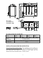
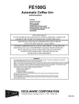
AUTOMATIC GAS
COFFEE URN
OPERATION MANUAL
MODEL:
FE-100G
SPECIFICATIONS
INSTALLATION
MAINTENANCE TIPS
REPAIR PARTS LIST
WIRING DIAGRAMS
GAS SPECIFICATIONS
MODEL NO.
FE-100G
NATURAL GAS
BTU/HR @ 3.5” W.C.
32,000
PROPANE GAS
BTU/HR @ 10” W.C.
32,000
FOR YOUR SAFETY
DO NOT STORE OR USE GASOLINE OR OTHER FLAMMABLE VAPORS AND
LIQUIDS IN THE VICINITY OF THIS OR ANY OTHER APPLIANCE.
THIS INSTALLATION MUST CONFORM WITH THE NATIONAL FUEL GAS CODE,
ANSI Z223.1 (LATEST EDITION).
WARNING: IMPROPER INSTALLATION, ADJUSTMENT, ALTERATION, SERVICE
OR MAINTENANCE CAN CAUSE PROPERTY DAMAGE, INJURY OR DEATH. READ
THE INSTALLATION, OPERATING AND MAINTENANCE INSTRUCTIONS
THOROUGHLY BEFORE INSTALLING OR SERVICING THIS EQUIPMENT.
CECILWARE CORPORATION
TH
43-05 20
AVENUE, LONG ISLAND CITY, NY 11105-1295
• 718 932-1414
N529A 08/99 DS
SAFETY PRECAUTIONS
FOR YOUR SAFETY, THE FOLLOWING SAFETY PRECAUTIONS SHOULD
BE FOLLOWED AND ENFORCED.
IF YOU SMELL GAS:
• OPEN WINDOWS
• DON’T TOUCH ELECTRICAL SWITCHES
• EXTINGUISH OPEN FLAMES
• IMMEDIATELY CALL YOUR GAS SUPPLIER
1. Instructions must be posted in a prominent location and all safety
precautions taken in the event the user smells gas. Obtain this
information from your local gas supplier.
2. LIGHTING: Follow the instruction on page 6 and label attached to
right side of coffee urn.
3. Do not place anything over the flue opening.
4. Do not place combustibles or non-combustible materials in the
proximity of coffee urn as this could cause fires or obstruct air flow to
the main burners.
5. This installation must conform with local codes, or in absence of local
codes with the National Fuel Gas Code ANSI Z223.1, latest edition.
6. Provide adequate air supply and ventilation.
7. Provide adequate clearance for air openings into the combustion
chamber.
8. Provide clearance for servicing and proper operation. Minimum
clearance from combustible construction 8” from back and 6” from
side.
9. Boiler must be disconnected from gas supply during any pressure
testing of pipelines in excess of ½ psig, and isolated (by turning off
gas shut-off valve) during any testing less than ½ psig.
10. Retain this manual for future reference.
UNPACKING INSTRUCTION: Carefully unpack the coffee urn and inspect
immediately for shipping damages. Your automatic coffee urn was
shipped in a carton designed to give maximum protection in normal
handling. It was thoroughly inspected before leaving the factory and the
carrier accepted and signed for it. File any claims for shipping damage or
irregularities with the carrier.
ELECTRICAL CONNECTIONS:
Cord Type Plug-in
120 VAC, 15 AMP, 50/60 Hz
POWER REQUIREMENTS:
3 AMP @ 120 VAC, 50/60 Hz
2
FE-1 0 0 G
AUTOM ATIC
COFFEE URN
FE-100G AUTOMATIC COFFEE URN
Dimensions
Body
Overall
Overall
Overall
(inch)
Depth
Depth
Height
Width
16.0
19.5
31.0
37.0
Water
¼” Copper tubing
connection
Construction
Type 304 18-8 Stainless Steel
Shipping Wt.
125 lb.
INSTALLATION AND OPERATING INSTRUCTION:
PRE-INSTALLATION INSTRUCTIONS: The installation of your coffee urn
must be made by a licensed plumber and the installation must conform
with State and Local Codes or in absence of Local Codes, with the
National Fuel Gas Code ANSI Z223.1 a latest version.
3
AIR SUPPLY AND VENTILATION: Adequate ventilation and air supply
must be provided in order for the coffee urn to operate properly and
efficiently. The area in front of and above the unit must be clear to avoid
any obstruction of flow of combustion and ventilation air. DO NOT under
any circumstances, connect the coffee urn flue directly to a building
exhaust system or place the flue outlet directly into the plenum of the
exhaust hood as it will adversely affect the gas combustion of the coffee
urn.
CLEARANCES: Your coffee urn is design certified to use on combustible
floors. The side and back clearances for combustible constructions are as
follows: 6 inches from side and 8 inches from back. The coffee urn must
be installed with 4 inch high legs provided.
GAS CONNECTION: Examine the gas specification label attached to the
urn to be certain that the type of gas for which the unit is equipped is
the same as the gas supply. A 3/8 NPT gas connection is needed to
connect the unit to the gas line. An accessible manual shut-off valve
must be installed in the gas supply line in case of an emergency. The gas
supply pipe must be sized to accommodate all the gas fired equipment
that may be connected to it. Check with your local Gas Company as to
proper pipe size. Sealant on all pipe joints must be resistive to propane
gas. Before attempting to light the coffee urn, check all joints for gas
tightness using a soap and water solution.
WATER CONNECTION: Unit is supplied with a water strainer and a 19”
length of ¼” copper tubing with a flare fitting. Connect the copper tubing
with the flare fitting to the water connection at the rear of the machine.
The other end of the strainer is connected with a suitable length of ¼”
tubing and a shut-off valve (supplied by a plumber) to a cold water
supply. Water pressure should be minimum of 20 lbs. for proper
operation.
To turn on the water supply valve plug the line cord into a 120 V
grounded outlet. The water will start entering the unit and automatically
fill it to capacity.
LIGHTING AND ADJUSTMENT: Water must be visible in the sight glass
before lighting to pilot. Turn the thermostat knob to its lowest position.
Turn gas cock dial to PILOT position. Depress gas cock dial and light pilot
with a long lighted match through the opening located on the bottom of
the urn. Hold in depressed position for approximately 30 sec. or until
pilot remains lit when dial is released.
NOTE: On the first lighting it may be necessary to hold the dial for a
longer period to allow trapped air to escape from the line.
DIAL SETTINGS AND CORRESPONDING WATER TEMPERATURES:
“1”= 50F, “10”=198F
4
FE-1 0 0G
AUTOM ATI C GAS
COFFE URN
PARTS LIST FOR FE-100G GAS SYSTEM
NO
1
2
3
4
5
6
7
8
9
10
11
12
13
14
15
16
17
18
19
20
21
22
DESCRIPTION
SIDE BOX DOOR
SIDE BOX
WASHER 2"
HEX BUSHING 3/4 X 3/8 NPT
SPACER 1/4"
GAS VALVE R/S 7000MVRLC
3/8 NPT 4" NIPPLE, BLACK
1/4 COMP FITTING
1/4 ALUM PILOT TUBE
3/8 X 3/8 NPT L COMP FITTING
3/8 ALUM GAS VALVE TUBE
THERMOSTAT RX-2051-12
WIRING HARNESS
8-32 HEX NUT
#10 STAR WASHER
8-32 X 3/4" WELD STUD
THERMOPILE
PILOT ASSEMBLY
ORIFICE,NAT
ORIFICE, LP
BURNER
MANIFOLD
8-32 X 5/8 SCREW
LP CONVERSION KIT
5
RZ46A
RZ45A
P528A
K636A
K641A
L621A
J015A
K039A
H350A
K635A
H349A
L622A
CH32A
P010A
P072A
P125A
F178A
F144A
F098A
F126A
G090Q
F044A
P526A
L347P
RELIGHTING: Shut off all gas and wait approximately 3 minutes before
relighting the pilot.
SHUTTING DOWN: For temporary shut down, turn the thermostat to
lowest or OFF position; then turn gas cock dial to PILOT position. To shut
boiler down completely, partially depress and turn gas cock dial to OFF
position.
CORRECT PROCEDURES FOR BREWING COFFEE AS
RECOMMENDED BY THE COFFEE BREWING CENTER
•
•
•
•
•
•
Use fresh or drip grind coffee, spread evenly, as an even coffee bed is
important for proper extraction.
Urn should be connected to cold water supply and the water heated
sufficiently to insure brewing temperatures of 195-205F (90-96C).
Leave cover on urn during brewing. Total contact time for urn grind
should be approximately 4-6 minutes.
Remove grounds and filter basket immediately after water has
dripped through.
If automatic agitation is not incorporated, mix brew by drawing off
heavy coffee from bottom of batch and pouring back into brew. Mix at
least one gallon per pound of coffee used.
Never repour brewed coffee back through spent grounds.
Hold coffee at 185-190F (85-88C) for proper serving temperature.
Brewed coffee should not be held for longer than one hour; it should
never be reheated if allowed to cool, and it should never be boiled.
TIMER: An electronic solid state timer is used to control the volume of
water for brewing the coffee. The timers are preset at the factory to
deliver 2.5 gallons of water for each brewing cycle.
However, if other volumes of water are desired, or a correction is
necessary, follow these instructions:
To increase volume of water, turn the timer knob clockwise. To
decrease the volume of water turn the knob counter-clockwise. Run
through a complete cycle for each setting. Note that the timer cannot be
readjusted once it is activated. To terminate the cycle if the liner
overflows, simply activate the cycle stop switch at the bottom of the
control box. If the maximum setting of the timer fails to deliver enough
water, check the water pump and spray head and follow instructions
under maintenance.
SPRAY ARM & BY-PASS ADJUSTMENT: Urns equipped with an adjustable
by-pass are delivered from the factory with the by-pass adjusted. If
further by-pass adjustment are required to correct local water
conditions, proceed as follows:
Place the spray head over the center of the right coffee liner and
activate the brew cycle switch. Insert a screwdriver in the by-pass
6
adjustment slot and turn it counter-clockwise to increase or clockwise to
decrease by-pass flow. At the completion of the brewing cycle, measure
the volume of the water in the coffee liner. The timer may have to be
readjusted to obtain the correct volume of water. The proper setting of
the by-pass will have to be determined by the user.
THERMOSTAT: To adjust the temperature of the water in the urn, turn
the thermostat knob to “10”and remove the knob without moving the
thermostat shaft. Place narrow bladed screwdriver (1/8”) into the hollow
thermostat shaft and engage center adjustment screw. When
thermometer reading approaches 198F slowly turn the adjustment screw
clockwise until the burner goes out. Turning the screw counter-clockwise
will increase the temperature.
MAINTENANCE TIPS
WATER CONDITION: Remove and clean spray head cap and spray head
disc frequently-typically once a week. To clean the swivel valve, loosen
nut and remove spray arm assembly from urn. Sediment may be
removed by inserting a pipe cleaner through small hole in valve. If
maximum setting of timer fails to deliver enough water, check water
pump.
OUTSIDE SERVICE: Should you require help, contact the factory, your
factory representative, or your local service company.
FOR QUALIFIED SERVICE PERSONNEL ONLY
When servicing of unit is required, contact a qualified service agency.
CAUTION: DO NOT TURN ON THERMOSTAT BEFORE ALL PRIMING
INSTRUCTIONS ARE COMPLETED.
•
WATER FROM COLD WATER SUPPLY LINE DOES NOT ENTER URN
1.
2.
3.
4.
Check water supply to shut-off valve and strainer.
Check fuse () on the front panel and replace it if necessary.
If steps 1 & 2 are in order, remove fuse and lift control box door.
Remove two screws from timer panel and remove timer exposing
terminal strip and electrical wiring.
5. Replace fuse.
6. Place wire jumper across terminals () and () on terminal board (). If
water enters urn, float switch is inoperative and should be replaced
(see par10). If water does not enter urn, then solenoid valve () or
small relay () is not functioning. To check solenoid valve, disconnect
leads from the coil and apply 115V power. If solenoid operates
replace relay.
7
•
REPLACING SOLENOID VALVE.
1. Shut off water supply and remove fuse () from front panel.
2. Disconnect wires from terminals on solenoid coil.
3. Remove flare nut from solenoid valve and unscrew valve solenoid
from bracket.
4. Install new unit.
•
REPLACING FLOAT SWITCH.
1. Remove fuse () from front panel.
2. Remove screws from timer panel and remove timer exposing terminal
board and electrical wiring.
3. Disconnect wires from terminals () and () on terminal board and
release float switch wires (see ill. X)
4. Unscrew packing nut from bottom of float mechanism and remove
cartridge () by pulling on the wires.
5. Replace with new cartridge and assemble unit and wiring in reverse
order.
•
CLEANING FLOAT CONTAINER
Periodically it may become necessary to clean out float container () to
keep float switch in proper operating condition:
1. Remove float can cover () from top of control box exposing ball float
() and stem.
2. Lift ball from stem.
3. Clean container and all parts and reassemble unit.
4. Replace cover.
•
AUTOMATIC REFILL OVERFLOWS
Remove fuse () from front panel, water should cease flowing which
indicates float switch is inoperative. However, if water still continues to
flow, valve in solenoid is lodged or dirty and should be replaced.
•
NO WATER FROM SPRAY HEAD
1. Check panel fuse () first.
2. Depress BREW button () and note if pilot light remains lit when button
is released. If pilot light stays on, we can assume water pump is not
operating. Remove side panel and check if fan on water pump is not
rotating; then pump should be replaced.
•
REPLACING WATER PUMP
1. Turn off water and electrical power from urn.
2. Drain urn to level of center faucet.
8
3. Open the control box and disconnect the two pump wires from the
quick disconnect terminals.
4. Loosen union fittings on pump and remove pump from urn.
5. Replace pump and follow priming instruction.
NOTE: Pump and motor assembly is factory lubricated for the life of the
pump.
•
TIMER SOLID-STATE
Depress BREW button, hold for approximately 10 seconds, and then
release. If water flows from spray head when button is depressed and
stops flowing after button is released, then timer is faulty and should be
replaced. No water from spray head when button is depressed, indicates
BREW button is fault and must be replaced.
•
AGITATOR
OPERATION: The agitator pump circuit is programmed to operate when
the BREW button is pushed. Upon completion of the pump cycle, the
agitator pump will pump air through the manifold into the coffee gauge
glasses and into the coffee liner. The completed cycle will take
approximately 20 second. The agitator may be operated independently
of the brewing cycle, if the agitator button is depressed.
MAITENANCE: The air pump is capable of delivering enough air for
proper blending. However if enough agitation is not present, check
flexible tubing on top of gauge glasses and fittings, for possible air leaks.
If air pump does not operate on completion of brewing cycle or when
agitation button is depressed, replace air pump or solid state agitator
timer (black box).
•
BURNER MAITENANCE
The two main burners can be removed by first removing the base cover
panel and unfastening the burner ends. The main burners should be
cleaned both inside the venturi portion and on the outside using a soft
bristle brush. The main burners must be into the same position before
removal. Once a year, a qualified service agency should be contacted to
inspect the appliance for safe and proper operation.
PILOT ADJUSTMENT CAP
•
SAFETY PILOT:
Remove pilot adjustment cap on
the gas valve and turn adjustment
screw to provide properly sized
flame (3/4 inch long).
Replace the cap.
F P I LO
F
T
O
NO
9
IN
PARTS LIST ME-10/15G
NO
1
2
3
4
5
6
7
8
9
10
11
12
13
14
15
16
17
18
19
20
21
22
23
24
25
26
27
28
29
30
31
32
33
34
35
36
37
38
39
40
41
42
43
44
45
46
47
48
49
50
DESCRIPTION
KNOB
COVER
BODY
GAUGE SHIELD MTG BRACKET
VENT CAP ASSEMBLY
GAUGE SHIELD WASHER KIT
WATER GAUGE GLASS
WATER GAUGE SHIELD
DIAL THERMOMETER
CHROME PLATED NUT 3/8" NPT
OVERFLOW TUBE
HANDLE
BONNET
FAUCET SPRING SS
STEM
CUP SEAT
FAUCET
SHANK
OVERFLOW DRAIN
BURNER SUPPORT BRACKET
LEGS SET OF 4
T-BURNER
PILOT SUPPORT BRACKET
PILOT ASSEMBLY, NAT
PILOT ASSEMBLY, LP
ORIFICE, NAT
ORIFICE, LP
WASHER SS
REDUCING COUPLING 1/4 X 3/8 "
ORIFICE BRACKET
SIDE BOX
SLIDE
THERMOSTAT
THERMOPILE
WIRING HARNESS
3/8 STREET ELBOW, BLACK STEEL
1/4 COMPRESSION FITTING
1/4 PILOT TUBE, ALUM
BLACK NIPPLE, 3/8 NPT X 4"
GAS VALVE
ELBOW COMP FTG, BRASS 3/8 X 3/8 NPT
3/8 GAS VALVE TUBE
SCREW, 8-32 X 3/8
GAS VALVE BRACKET
SIDE BOX DOOR
SIDE BOX BACK
STAR WASHER, #10
HEX NUT, 8-32
WELD STUD, 8-32 X 3/4
HEX BUSHING 3/4 X 3/8
FLUE
VENT CAP
10
ME-10G
M027A
Q102H
R477A
U160A
X046A
X012A
X043A
D031A
L007A
K110A
H081A
X007A
X010A
X019A
X058A
X014A
X149A
D021A
E009A
R483A
M005A
G052A
U670A
F135A
F134A
F160A
F161A
P813A
J041A
U674A
RZ16A
UB12A
L622A
F178A
CH32A
J040A
K039A
H345A
J015A
L621A
K635A
H346A
P013A
UB11A
RZ17A
RZ18A
P072A
P010A
P125A
K636A
R481A
U019A
ME-15G
M027A
Q102H
R478A
U160A
X046A
X012A
X073A
D066A
L007A
K110A
H080A
X007A
X010A
X019A
X058A
X014A
X149A
D021A
E009A
R483A
M005A
G052A
U670A
F135A
F134A
F160A
F161A
P813A
J041A
U674A
RZ16A
UB12A
L622A
F178A
CH32A
J040A
K039A
H345A
J015A
L621A
K635A
H346A
P013A
UB11A
RZ17A
RZ18A
P072A
P010A
P125A
K636A
R481A
U019A
51
52
53
54
55
56
SILICONE GASKET
STEM VALVE
ADAPTER 1/4-20
FLOAT, SS 3"
LP CONVERSION KIT
WATER GAUGE ASSEMBLY
FAUCET ASSEMBLY
M256A
M0251
M0589
M0892
L347P
D017A
11
M256A
M0251
M0589
M0892
L347P
D020A
D017A