1
EPSON
COLOR INK-JET PRINTER
EPSON Stylus Color 400
SERVICE MANUAL
SEIKO EPSON CORPORATION
4007366
NOTICE
All rights reserved. Reproduction of any part of this manual in any form whatsoever
without SEIKO EPSON’s express written permission is forbidden.
The contents of this manual are subjects to change without notice.
All efforts have been made to ensure the accuracy of the contents of this manual.
However, should any errors be detected, SEIKO EPSON would greatly appreciate
being informed of them.
The above notwithstanding SEIKO EPSON can assume no responsibility for any errors
in this manual or the consequences thereof.
EPSON is a registered trademark of SEIKO EPSON CORPORATION.
General Notice:
Other product names used herein are for identification purposes only and may be
trademarks or registered trademarks of their respective companies.
Copyright 1997 by SEIKO EPSON CORPORATION
Nagano, Japan
PRECAUTIONS
Precautionary notations throughout the text are categorized relative to 1) personal injury and 2)
damage to equipment.
WARNING
Signals a precaution which, if ignored, could result in serious or fatal personal injury.
Great caution should be exercised in performing procedures preceded by
WARNING Headings.
CAUTION
Signals a precaution which, if ignored, could result in damage to equipment.
The precautionary measures itemized below should always be observed when performing
repair/maintenance procedures.
WARNING
1. ALWAYS DISCONNECT THE PRODUCT FROM BOTH THE POWER SOURCE AND
PERIPHERAL DEVICES PERFORMING ANY MAINTENANCE OR REPAIR PROCEDURES.
2. NO WORK SHOULD BE PERFORMED ON THE UNIT BY PERSONS UNFAMILIAR WITH
BASIC SAFETY MEASURES AS DICTATED FOR ALL ELECTRONICS TECHNICIANS IN
THEIR LINE OF WORK.
3. WHEN PERFORMING TESTING AS DICTATED WITHIN THIS MANUAL. DO NOT
CONNECT THE UNIT TO A POWER SOURCE UNTIL INSTRUCTED TO DO SO. WHEN THE
POWER SUPPLY CABLE MUST BE CONNECTED, USE EXTREME CAUTION IN WORKING
ON POWER SUPPLY AND OTHER ELECTRONIC COMPONENTS.
CAUTION
1. REPAIRS ON EPSON PRODUCT SHOULD BE PERFORMED ONLY BY EPSON CERTIFIED
REPAIR TECHNICIAN.
2. MAKE CERTAIN THAT THE SOURCE VOLTAGE IS THE SAME AS THE RATED VOLTAGE,
LISTED ON THE SERIAL NUMBER/RATING PLATE. IF THE EPSON PRODUCT HAS A
PRIMARY AC RATING DIFFERENT FROM AVAILABLE POWER SOURCE, DO NOT
CONNECT IT TO THE POWER SOURCE.
3. ALWAYS VERIFY THAT THE EPSON PRODUCT HAS BEEN DISCONNECTED FROM THE
POWER SOURCE BEFORE REMOVING OR REPLACING PRINTED CIRCUIT BOARDS
AND/OR INDIVIDUAL CHIPS.
4. IN ORDER TO PROTECT SENSITIVE MICROPROCESSORS AND CIRCUITRY, USE
STATIC DISCHARGE EQUIPMENT, SUCH AS ANTI-STATIC WRIST STRAPS, WHEN
ACCESSING INTERNAL COMPONENTS.
5. REPLACE MALFUNCTIONING COMPONENTS ONLY WITH THOSE COMPONENTS BY
THE
MANUFACTURE;
INTRODUCTION
OF
SECOND-SOURCE
ICs
OR
OTHER
NONAPPROVED COMPONENTS MAY DAMAGE THE PRODUCT AND VOID ANY
APPLICABLE EPSON WARRANTY.
PREFACE
This manual describes functions, theory of electrical and mechanical operations, maintenance, and
repair of EPSON Stylus Color 400.
The instructions and procedures included herein are intended for the experience repair technician,
and attention should be given to die precautions on the preceding page. The Chapters are
organized as follows:
CHAPTER 1. GENERAL DESCRIPTION
Provides a general product overview, lists specifications, and illustrates the main components of the
printer.
CHAPTER 2. OPERATING PRINCIPLES
Describes the theory of printer operation.
CHAPTER 3. DISASSEMBLY AND ASSEMBLY
Includes a step-by-step guide for product disassembly and assembly.
CHAPTER 4. ADJUSTMENT
Includes a step-by-step guide for adjustment.
CHAPTER 5. TROUBLESHOOTING
Provides EPSON-approved techniques for troubleshooting.
CHAPTER 6. MAINTENANCE
Describes preventive maintenance techniques and lists lubricants and adhesives required to
service the equipment.
APPENDIX
Describes connector pin assignments, circuit diagrams, circuit board component layout and
exploded diagram.
The contents of this manual are subject to change without notice.
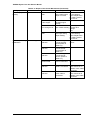
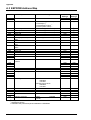
REVISION SHEET
Revision
Issued Data
Contents
Rev. A
February18. 1997
First issue
TABLE OF CONTENTS
CHAPTER 1.
CHAPTER 2.
CHAPTER 3.
CHAPTER 4.
CHAPTER 5.
CHAPTER 6.
APPENDIX
GENERAL DESCRIPTION
OPERATING PRINCIPLES
DISASSEMBLY AND ASSEMBLY
ADJUSTMENT
TROUBLESHOOTING
MAINTENANCE
Chapter 1
Product Descriptions
1.1 Features.................................................................................................................1-1
1.2 Specifications .......................................................................................................1-2
1.2.1 Printing Specification............................................................................................................. 1-2
1.2.2 Paper Specification ................................................................................................................ 1-4
1.2.2.1 Cut Sheet................................................................................................................... 1-4
1.2.2.2 Transparency, Glossy Paper ..................................................................................... 1-4
1.2.2.3 Envelope.................................................................................................................... 1-4
1.2.2.4 Index Card................................................................................................................. 1-4
1.2.3 Adjust Lever Settings (PG adjust lever) ............................................................................... 1-5
1.2.4 Printing Area ........................................................................................................................... 1-5
1.2.5 Environmental Condition....................................................................................................... 1-8
1.2.6 Ink Cartridge Specifications .................................................................................................. 1-9
1.2.7 Physical Specification.......................................................................................................... 1-11
1.2.8 Input Data Buffer .................................................................................................................. 1-11
1.2.9 Electric Specification ........................................................................................................... 1-12
1.2.10 Reliability............................................................................................................................. 1-12
1.2.11 Safety Approvals................................................................................................................. 1-12
1.2.12 Acoustic Noise.................................................................................................................... 1-13
1.2.13 CE Marking .......................................................................................................................... 1-13
1.2.14 Printer Language and Emulation ...................................................................................... 1-13
1.3 Interface...............................................................................................................1-15
1.3.1 Parallel Interface (Forward Channel) .................................................................................. 1-15
1.3.2 Parallel Interface (Reverse Channel) .................................................................................. 1-16
1.3.3 Prevention Hosts from Data Transfer time-out.................................................................. 1-18
1.4 Control Panel ......................................................................................................1-19
1.4.1 Indicators............................................................................................................................... 1-19
1.4.2 Panel Functions.................................................................................................................... 1-20
1.4.3 Printer Condition and Panel Status .................................................................................... 1-22
1.5 Error Status.........................................................................................................1-23
1.5.1 Ink Out ................................................................................................................................... 1-23
1.5.2 Paper Out............................................................................................................................... 1-23
1.5.3 Paper Jam.............................................................................................................................. 1-23
1.5.4 No Ink-Cartridge ................................................................................................................... 1-24
1.5.5 Maintenance Request........................................................................................................... 1-24
1.5.6 Fatal Errors............................................................................................................................ 1-24
1.6 Printer Initialization ............................................................................................1-25
1.7 Initialization Settings..........................................................................................1-25
1.8 Main Components...............................................................................................1-26
1.8.1 Printer Mechanism ............................................................................................................... 1-26
1.8.2 C206 Main Control Board..................................................................................................... 1-26
1.8.3 C206 PSB/PSE Power Supply Board .................................................................................. 1-27
1.8.4 C206PNL(Panel) Board ........................................................................................................ 1-27
EPSON Stylus Color 400 Service Manual
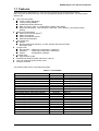
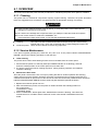
1.1 Features
Stylus Color 400 is designed for PC users at home and low price for that high performance.
Also, this printer has the same high color print quality(720X720dpi) as Stylus ProXL. The major printer
features are;
High color print quality
720(H) x 720(V) dpi printing
4 color printing (YMCBk)
Traditional and New Microwave
Black 64 nozzles, CMY 21 nozzles (Black=180dpi, CMY=90dpi)
During 360 dpi printing, 1 dot is fired by 2 shots and 1 dot is fired by 1 shot during 720 dpi
printing.
Built-in auto sheet feeder
2
Holds 100 cut-sheets (55g/m )
Holds 10 envelopes
Holds 10 transparency films
Holds 65 special papers
High-speed print
200cps
By using head drive frequency 14.4KHz, printing speed is twice faster
than Stylus Color.
Compact size
Non-operating : 429mm(W) x 234mm(D) x 162mm(H)
Operating
: 429mm(W) x 695mm(D) x 309mm(H)
Weight
: 5.2Kg(without cartridge)
Acoustic noise
Approximately 45 dB
Bi-directional parallel I/F(IEEE-1284 level 1 device)
One unit combined black and CMY head
Windows exclusive
The following table shows consumable and option.
Table 1-1. Consumable
Item
Black Ink Cartridge
Color Ink Cartridge
EPSON 360 dpi Ink Jet Paper
EPSON 360 dpi Ink Jet Paper
EPSON 360 dpi Ink Jet Paper
Photo Quality Ink Jet Paper
Photo Quality Ink Jet Paper
Photo Quality Ink Jet Paper
Photo Quality Ink Jet Paper
Photo Quality Glossy Paper(New Release)
Photo Quality Glossy Paper(New Release)
Photo Quality Glossy Film
Photo Quality Glossy Film
Photo Quality Glossy Film
Ink Jet Transparencies
Ink Jet Transparencies
Photo Quality Ink Jet Card
Photo Quality Ink Jet Card
Photo Quality Ink Jet Card
Photo Quality Self Adhesive Sheet
Rev. A
Code
S020093
S020089
S041025
S041059
S041060
S041026
S041061
S041062
S041067
S041126
S041124
S041071
S041124
S041107
S041063
S041064
S041054
S041121
S041122
S041106
Remark
Color: Black
Color: Cyan/Magenta/Yellow
Size: A4(200 sheets)
Size: A4(100 sheets)
Size: Letter(100 sheets)
Size: A4(200 sheets)
Size: A4(100 sheets)
Size: Letter
Size: Legal
Size: A4
Size: Letter
Size: A4
Size: Letter
Size: A6
Size: A4
Size: Letter
Size: A6
Size: 5 x 8 inches
Size: 10 x 8 inches
Size: A4
1-1
Chapter1 Product Description
1.2 Specifications
This section describes each specification for Stylus Color 400; 1) Printing specification, 2) Paper
specification, 3) Adjust lever settings, 4) Printing area, 5) Environmental condition, 6) Ink Cartridge
specification, 7) Physical specification, 8) Electric specification, 9) Reliability.
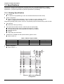
1.2.1 Printing Specification
Print method
On demand ink jet (MACH type. One unit combined with black and CMY head)
Nozzle configuration
Black 64 nozzles (32x2 staggered), Color 21 nozzles x 3 (Cyan, Magenta, Yellow)
(Black = Staggering 2 lines, 180 dpi, CMY= one line for each color, 90 dpi)
Note) During 360 dpi printing mode, one line is completed by 2-pass for black and by 4-pass for CMY.
Print direction
Bi-direction with logic seeking
Print speed and Printable columns, character pitch and print quality
360 dpi printing mode= 200 cps (Head drive frequency 14.4KHz)
720 dpi printing mode= 200 cps (Head drive frequency 14.4KHz)
About 80 columns
10 pitch
High quality (No draft mode)
Printable area, available dot CR speed at Raster graphics mode
Refer to table 1-2.
Table 1-2.Raster Graphics Mode
Horizontal resolution
180 dpi
360 dpi
720 dpi
Printable area
8.26 inch
8.26 inch
8.26 inch
Available dot
1488
2976
5952
CR Speed
20 IPS
20 IPS
20 IPS
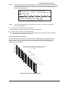
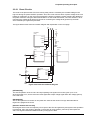
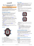
Nozzle configuration
Refer to figure 1-1.
#1
90DPI
180DPI
#3
#5
2.2578 mm
(Y)
10.16 mm
2.2578 mm
7.9022 mm
Y1
M1
C1
Y2
M2
C2
Y3
M3
C3
Y4
M4
C4
Y19
M 19
C19
#59
Y20
M 20
C20
#61
Y21
M 21
C21
#63
(M)
#23
(C)
#24
#25
#26
(B2)
#60
#62
#64
(B1)
Figure1-1. Stylus Color 400 Nozzle
Configuration
1-2
Rev. A
EPSON Stylus Color 400 Service Manual
Feeding method
Friction feed with ASF
Paper feed resolution
0.035mm(1/720 inch)
Line spacing
1/6 inch or programmable at 1/360 inch
Paper path
Cut-sheet ASF(Top entry)
Feeding speed
66.6ms (1/6 inch)
153.7ms (9.03mm line spacing)
76.2ms (continues 3.0 inch/sec)
Ink supply
Exclusive ink cartridge(Black and CMY)
Paper holding capacity of Hopper
Size
: Index card ∼Legal
Thickness
: Less than 8mm
Paper capacity
: 100 Cut sheets
: 10 Envelopes
: 65 Coated papers (360 dpi)
: 65 Coated papers (720 dpi)
: 30 Glossy papers
: 10 Transparent sheets
: 30 Index cards
Note) Those numbers above should be considered as reference. The actual paper accumulation should
be considered first.
Character tables
: 2 international character sets(Not Opened)
PC437(US, Standard Europe)
PC850(Multilingual)
Typeface
Bit map LQ font
: EPSON Courier 10CPI
Control code
ESC/P Raster
EPSON Remote command
Rev. A
1-3
Chapter1 Product Description
1.2.2 Paper Specification
This section describes the printable area and types of paper that can be used in this printer.
1.2.2.1 Cut Sheet
[Size]
: A4 [Width 210mm(8.3”) x Length 297mm(11.7”)]
: Letter [Width 216mm(8.5”) x Length 279mm(11.0”)]
: B5 [Width 182mm(7.2”) x Length 257mm(10.1”)]
: Legal [Width 216mm(8.5”) x Length 356mm(14.0”)]
: Statement [Width 139.7mm(5.5”) x Length 215.9mm(8.5”)]
: Exclusive [Width 190.5mm(7.5”) x Length 254mm(10”)]
[Thickness]
: 0.08mm(0.003”) - 0.11mm(0.004”)
[Weight]
: 64g/m (17Ib.) - 90g/m (24Ib.)
[Quality]
: Exclusive paper, Bond paper, PPC
2
2
1.2.2.2 Transparency, Glossy Paper
[Size]
: A4[Width 210mm(8.3”) x Length 297mm(11.7”)]
: Letter[Width 216mm(8.5”) x Length 279mm(11.0”)]
[Thickness]
: 0.075mm(0.003”) - 0.085mm(0.0033”)
Note) Transparency printing is only available at normal temperature.
1.2.2.3 Envelope
[Size]
: No.10 Width 241mm(9 1/2”) x Length 104.8mm(4 1/8”)
: DL Width 220mm(8.7”) x Length 110mm(4.3”)
: C6 Width 162mm(6.4”) x Length 114mm(4.5”)
[Thickness]
: 0.16mm(0.006”) - 0.52mm(0.02”)
[Weight]
: 45g/m (12Ib.) - 75g/m (20Ib.)
[Quality]
: Bond paper, Plain paper, Air mail
2
2
Note 1) Envelope printing is only available at normal temperature.
Note 2) Keep the longer side of the envelope horizontally at setting.
1.2.2.4 Index Card
[Size]
: A6 Index card: Width 105mm(4.1”) x Length 148mm(5.8”)
: A5 Index card: Width 148mm(5.8”) x Length 210mm(8.3”)
: 5x8” Index card: Width 127mm(5.0” x Length 203mm(8.0”)
: 10x8” Index card: Width 127mm(5.0”) x Length 203mm(8.0”)
[Thickness]
: Less than 0.23mm(0.0091”)
Note 1) No curled, wrinkled, scuffing or torn paper be used.
Note 2) Set the lever to the proper position according to the paper type you print. (Refer to section
1.2.3 for details)
Note 3) Printing should be performed at room temperature in spite of the paper types.
1-4
Rev. A
EPSON Stylus Color 400 Service Manual
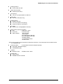
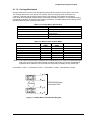
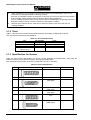
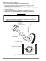
1.2.3 Adjust Lever Settings (PG adjust lever)
The adjust lever located on the right side(blue) under the printer cover needs to be set to the proper
position according to the paper you print. (Refer to the table below). Also, if there is any dirt caused by
friction on the wavy or wrinkled paper, this can be prevented by changing the lever position to rear
position (marked with “+”) in spite of paper types.
Table 1-3.Adjust Lever Settings
Paper
Normal paper,
Coated paper
Envelopes
Lever position
Front
PG adjustment value
0 mm (1.1mm between head and platen)
Rear
0.9 mm (2.0mm between head and platen)
Front (Mark "0")
Rear (Mark "+")
Level adjustment lever
CR Guide Shaft
Bush
Figure 1-2. Adjust Lever Settings
Rev. A
1-5
Chapter1 Product Description
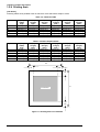
1.2.4 Printing Area
[Cut Sheet]
Following tables show printable areas at Character mode and Raster Graphics mode.
Table 1-4. Character Table
Paper size
PW(Paper
width)
(typ)
A4
210mm(8.3”)
Letter
216mm(8.5”)
B5
182mm(7.2”)
Legal
216mm(8.5”)
Statement 139.7mm(5.5”)
Executive 190.5mm(7.5”)
PL(Paper
Length)
(typ.)
297mm(11.7”)
279mm(11.0”)
257mm(10.1”)
356mm(14.0”)
215.9mm(8.5”)
254mm(10”)
LM(Left
margin)
(min.)
3mm(0.12”)
3mm(0.12”)
3mm(0.12”)
3mm(0.12”)
3mm(0.12”)
3mm(0.12”)
RM(Right
margin)
(min.)
3mm(0.12”)
9mm(0.35”)
3mm(0.12”)
9mm(0.35”)
3mm(0.12”)
3mm(0.12”)
TM(Top
margin)
(min.)
3mm(0.12”)
3mm(0.12”)
3mm(0.12”)
3mm(0.12”)
3mm(0.12”)
3mm(0.12”)
BM(Bottom
margin)
(min.)
14mm(0.54”)
14mm(0.54”)
14mm(0.54”)
14mm(0.54”)
14mm(0.54”)
14mm(0.54”)
TM(Top
margin)
(min.)
3mm(0.12”)
3mm(0.12”)
3mm(0.12”)
3mm(0.12”)
3mm(0.12”)
3mm(0.12”)
BM(Bottom
margin)
(min.)
14mm(0.54”)
14mm(0.54”)
14mm(0.54”)
14mm(0.54”)
14mm(0.54”)
14mm(0.54”)
Table 1-5. Raster Graphics Mode
Paper size
PW(Paper
width)
(typ)
A4
210mm(8.3”)
Letter
216mm(8.5”)
B5
182mm(7.2”)
Legal
216mm(8.5”)
Statement 139.7mm(5.5”)
Executive 190.5mm(7.5”)
PL(Paper
Length)
(typ.)
297mm(11.7”)
279mm(11.0”)
257mm(10.1”)
356mm(14.0”)
215.9mm(8.5”)
254mm(10”)
LM(Left
margin)
(min.)
3mm(0.12”)
3mm(0.12”)
3mm(0.12”)
3mm(0.12”)
3mm(0.12”)
3mm(0.12”)
RM(Right
margin)
(min.)
3mm(0.12”)
3mm(0.12”)
3mm(0.12”)
3mm(0.12”)
3mm(0.12”)
3mm(0.12”)
PW
LM
RM
TM
PL
Printable Area
BM
Figure 1-3. Printing Area for Cut Sheets
1-6
Rev. A
EPSON Stylus Color 400 Service Manual
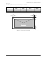
[Envelope]
The table and figure below show the printable area for envelopes.
Table 1-6. Printable Area for Envelope
Paper size
LM(Left margin)
(min.)
RM(Right margin)
(min.)
TM(Top margin)
(min.)
#10
DL
C6
3mm(0.12”)
3mm(0.12”)
3mm(0.12”)
28mm(1.10”)
7mm(0.28”)
3mm(0.12”)
3mm(0.12”)
3mm(0.12”)
3mm(0.12”)
BM(Bottom
margin)
(min.)
14mm(0.55”)
14mm(0.55”)
14mm(0.55”)
RM
LM
TM
Printable area
BM
Figure 1-4. Printing Area for Envelope
Rev. A
1-7
Chapter1 Product Description
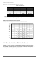
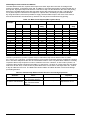
1.2.5 Environmental Condition
Temperature
Operating
:10 to 35 °C (Refer to the figure below for condition)
Non-operating
: -20 to 60 °C(with shipment container)
Note) 1 month at 40 °C and 120 hours at 60 °C
Humidity
Operating
Non-operating
: 20% 80% RH (without condensation. Refer to the figure below for
condition)
: 5% 85% RH (without condensation and with shipment container)
Humidity
(% RH)
80%
Guaranteed range
55%
20%
10°C
(50°F)
27°C
(80°F)
35°C
(95°F)
°C
(°F)
Figure 1-5. Temperature/Humidity of Range
Resistance to shock
Operating
Non-operating
Resistance to vibration
Operating
: 0.15G, 1055Hz
Non-operating
: 0.50G, 1055Hz
Note 1)
Note 2)
Note 3)
Note 4)
1-8
: 1G, within 1 ms
: 2G, within 2 ms
X,Y,Z directions
X,Y,Z directions (with shipment container)
X,Y,Z directions
X,Y,Z directions (with shipment container)
During non-operating, make sure that the head is capped.
During the transport, make sure that the head is capped and ink cartridge is
installed to the printer.
If the head is not capped at the power-off state, turn the power on with installed ink
cartridge and turn off the power after confirming that Power on operation is completed and
the head is capped.
Ink will be frozen under -4°C environment, however it will be useable after placing it
more than 3 hours at 25°C.
Rev. A
EPSON Stylus Color 400 Service Manual
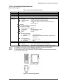
1.2.6 Ink Cartridge Specifications
[Black Ink Cartridge]
Table 1-7.Black Cartridge Specification
Item
Type
Color
Print capacity
Validity
Environmental
conditions
Specifications
Exclusive cartridge
Black
540 pages / A4 (ISO/IE10561 Letter Pattern at 360 dpi)
2 years (sealed in package) / 6months(out of package)
Temperature
Storage
: -20°C40°C(within a month at 40°C)
Packing storage : -30°C40°C (within a month at 40°C)
Transit
: -30°C60°C (within 120 hours at 60°C and within a
month at 40°C)
Humidity
5%85%(without condensation)
Resistance to vibration
Sealed in package : 555Hz
Acceleration
: 29.4m/s less than <3G>
Direction
: X, Y, Z direction
Time
: 1 hour
Drop
Sealed in package :
Dropping height
: Less than 0.08m
Direction
: Drop the printer facing the bottom, sides and one
edge down.
Out of package:
Dropping height
: Less than 1.50m
Frequency
: Once
19.8mm(W) x 52.7(D) x 38.5mm(H)
Total ink cartridge : 54g
Total ink
: 16.4 ± 0.5g (Quantity in the ink cartridge)
Consumable ink : More than 12.1g(Useable ink quantity until ink ends)
Dimension
Weight
Note 1)
Note 2)
Note 3)
Ink cartridge can not re-fill, only ink cartridge is prepared for article of consumption.
Do not use the ink cartridge which is passed away the ink life.
Ink will be frozen under -4°C environment, however it will be usual after placing it more than
3 hours at room temperature.
19.8
52.7
51.2
38.5
18.3
Figure 1-6. Ink Cartridge (Black)
Rev. A
1-9
Chapter1 Product Description
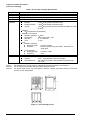
[Color Ink Cartridge]
Table 1-8. Color Ink Cartridge Specification
Item
Type
Color
Print capacity
Validity
Environmental
conditions
Specifications
Exclusive cartridge
Magenta, Cyan, Yellow
320 pages / A4 (360 dpi, 5% duty each color)
2 years (sealed in package) / 6months(out of package)
Temperature
Storage
: -20°C40°C (within a month at 40°C)
Packing storage : -30°C40°C (within a month at 40°C)
Transit
: -30°C60°C (within 120 hours at 60°C and within a month
at 40°C)
Humidity
5%85%(without condensation)
Resistance to vibration
Sealed in package : 555Hz
Acceleration
: 29.4m/s less than <3G>
Direction
: X, Y, Z direction
Time
: 1 hour
Drop
Sealed in package :
Dropping height
: Less than 0.08m
Direction
: Drop the printer facing the bottom, sides and one
edge down.
Out of package:
Dropping height
: Less than 1.50m
Frequency
: Once
42.9mm(W) x 52.7(D) x 38.5mm(H)
Total ink cartridge : 68g
Total ink
: 13.3 0.5g (Quantity in the ink cartridge)
Consumable ink : More than 10.1g/each color(Useable ink quantity until
ink ends)
Dimension
Weight
Note 1)
Note 2)
Note 3)
Ink cartridge can not re-fill, only ink cartridge is prepared for article of consumption.
Do not use the ink cartridge which is passed away the ink life.
Ink will be frozen under -4°C environment, however it will be usual after placing it more than
3 hours at room temperature.
43.2
51.2
52.7
42.9
38.5
41.4
Figure 1-7. Ink Cartridge (Color)
1-10
Rev. A
EPSON Stylus Color 400 Service Manual
1.2.7 Physical Specification
[Dimension]
: 429mm(W) x 234mm(D) x 162mm(H)
: 429mm(W) x 695mm(D) x 309mm(H) with extended stacker and paper support.
[Weight]
: 5.2Kg
1.2.8 Input Data Buffer
10 K byte
Rev. A
1-11
Chapter1 Product Description
1.2.9 Electric Specification
[120V version]
[Rated voltage]
: AC120V
[Input voltage range]
: AC103.5∼132V
[Rated frequency range]
: 50∼60Hz
[Input frequency range]
: 49.5∼60.5Hz
[Rated current]
: 0.4A(Max. 0.5A)
[Power consumption]
: Approx.15W(ISO/IEC 10561 Letter pattern)
: Energy Star compliant
[Insulation Resistance]
: 10M ohms min.(between AC line and chassis, DC500V)
[Dielectric strength]
: AC1000 V rms. 1 minute or AC1200 Vrms. 1 second (between AC
line and chassis)
[220∼240V version]
[Rated voltage]
: AC220V∼240V
[Input voltage range]
: AC198∼264V
[Rated frequency range]
: 50∼60Hz
[Input frequency range]
: 49.5∼60.5Hz
[Rated current]
: 0.2 A(Max. 0.3A)
[Power consumption]
: Approx.15W(ISO/IEC 10561 Letter pattern)
: Energy Star compliant
[Insulation Resistance]
: 10M ohms min.(between AC line and chassis, DC500V)
[Dielectric strength]
: AC1500 V rms. 1 minute (between AC line and chassis)
1.2.10 Reliability
[Total print volume]
[Print head life]
: 10,000 pages(A4, letter)
: 2000 million dots/nozzle
1.2.11 Safety Approvals
[120V version]
Safety standard
EMI
[220∼240V]
Safety standard
EMI
1-12
: UL1950 with D3
: CSA22.2 No.950 with D3
: FCC part 15 subpart B class B
: CSA C108.8 class B
: EN 60950(VDE,NEMKO)
: EN55022(CISPR Pub.22) class B
: AS/NZS 3548 class B
Rev. A
EPSON Stylus Color 400 Service Manual
1.2.12 Acoustic Noise
[Level]
: Approx.45 dB(A) (According to ISO 7779)
1.2.13 CE Marking
[220-240V version]
Low voltage Directive 73/23/EEC :EN60950
EMC Directive 89/336/EEC
:EN55022 Class B
EN61000-3-2
EN61000-3-3
EN50082-1
IEC801-2
IEC801-3
IEC801-4
1.2.14 Printer Language and Emulation
[Printer Language] : ESC/P Raster
: EPSON Remote
[ESC/P control codes]
< Character mode >
General Operation
Initialize Printer
: ESC@
Paper feeding
Form Feed
Line Feed
Carriage Return
: FF
: LF
: CR
<Graphic mode>
General operation
Initialize Printer
Unidirectional Printing
CSF Mode Control
: ESC@
: ESC U
: ESC EM
Paper feeding:
Form Feed
Line Feed
Line Spacing
Carriage Return
: FF
: LF
: ESC+
: CR
Page format
Page Length
Top/Bottom Margin
: ESC(C
: ESC(c
Print position motion
Horizontal Print Position
Vertical Print Position
: ESC$,ESC\
: ESC (V,ESC (v
Spacing
Define Unit
: ESC(U
Graphics
Graphics Mode
Raster Graphics
Micro weave control
: ESC(G
: ESC.
: ESC(i
Printing mode
Printing mode
: ESC(K
Rev. A
1-13
Chapter1 Product Description
Color
Printing color
: ESC r, ESC(r
EEPROM control
EEPROM control
: ESC
1-14
Rev. A
EPSON Stylus Color 400 Service Manual
1.3 Interface
This printer provides parallel interface as standard.
1.3.1 Parallel Interface (Forward Channel)
[Transmission mode]
[Synchronization]
[Handshaking]
[Signal level]
[Adaptable connector]
: 8 bit parallel, IEEE-1284 compatibility mode
: By /STOPBE pulse
: BY BUSY and /ACKLG signal
: TTL compatible level
: 57-30360(amphenol) or equivalent
BUSY signal is set high before setting either/ERROR low or PE high and held high until all these
signals return to their inactive state.
BUSY signal is at high level in the following cases.
During data entry (see Data transmission timing)
When input data buffer is full
During -INIT signal is at low level or during hardware initialization
During printer error (See /ERROR signal)
/ERROR signal is at low level when the printer is in one of the following states.
Printer hardware error (fatal error)
Paper-out error
Paper-jam error
Ink-out error
PE signal is at high level during paper-out error.
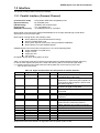
Table 1-9 shows the signal and connector pin assignments for parallel interface(forward channel*1).
In case of these signals, twist pair line is used and returning side is connected to signal GND.
(*1): Forward channel is the mode when the ordinary data such as an order to print is sent
from the PC to the printer.
Table 1-9. Signal and Connector Pin Assignment for Parallel Interface
Pin No.
1
Signal Name
/STROBE
2-9
DATA0-7
10
/ACKNLG
11
BUSY
12
13
PE
SLCT
14
31
/AFXT
/INIT
32
36
18
35
17
16,33,19-30
15,34
/ERROR
/SLIN
Logic H
+5V
Chassis GND
GND
NC
Return GND pin In/Out
Functional Description
19
In
The strobe pulse. Read-in of data is performed
at the falling edge of this pulse.
20-27
In
The DATA0 through DATA7 signals represent
data bits 0 to 7, respectively. Each signal is at
high level when data is logical 1 and low level
when data is logical 0.
28
Out This signal is a negative pulse indicating that
the printer can again accept data.
29
Out A high signal indicates that the printer cannot
receive data.
28
Out A high signal indicates paper-out error.
28
Out Always at high level when the printer is
powered on.
30
In
Not used.
30
In
The falling edge of a negative pulse or a low
signal on this line causes the printer to
initialize. Minimum 50 us pulse is necessary.
29
Out A low signal indicates printer error condition.
30
In
Not used.
Out Pulled up to +5V via 3.9K ohm resistor.
Out Pulled up to +5V via 3.3K ohm resistor.
Chassis GND.
Signal GND.
Not connected.
Note) In/Out refers to the direction of signal flow from the printer’s point of view.
Rev. A
1-15
Chapter1 Product Description
1.3.2 Parallel Interface (Reverse Channel)
[Transmission mode]
[Synchronization]
[Handshaking]
[Data trans. timing]
[Signal level]
: IEEE-1284 nibble mode
: Refer to the IEEE-1284 specification
: Refer to the IEEE-1284 specification
: Refer to the IEEE-1284 specification
: IEEE-1284 level 1 device
: TTL compatible level
[Adaptable connector] : 57-30360(amphenol) or equivalent
[Extensibility request]
: The printer responds affirmatively when the extensibility
request values are 00H or 04H, that mean,
00H :Request Nibble Mode Reverse Channel Transfer.
04H :Request device ID; Return Data using Nibble Mode Rev
Channel Transfer.
Note) The printer sends following device ID string when it is requested.
Table 1-10. Device ID Description
Contents
<00H>
<3CH>
MFG
EPSON
Production Maker
CMD
ESCPL2,BDC
Command system
MDL
Stylus[SP]Color[SP] 400
Model name
CLS
PRINTER
Class
Note) [00H] denotes a hexadecimal value of zero. MDL value depends on the EEPROM setting.
Note) MDL value depends on the EEPROM setting. Model name can be changed by changing a
certain address in the EEPROM.
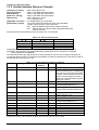
The table below shows pin assignment for reverse channel(*3). In these case of signals, twist pair line
is used and returning side is connected to Signal GND.(*3): Reverse channel is the mode that any data is
transferred from the printer to the PC.
Table 1-11. Pin Assignment for Reverse Channel
Signal Name
Return
In/Out
Functional description
GND pin
1
HostClk
19
In
Host clock signal.
2-9
Data0-7
20-27
In
The DATA0 through DATA7 signals
represent data bits 0 to7, respectively.
Each signal is at high level when data
is logical 1 and low level when data is
logical 0. These signals are used to
transfer the 1284 extensibility request
values to the printer.
10
PrtClk
28
Out
Printer clock signal.
11
PtrBusy, Data Bit-3,7
29
Out
Printer busy signal and reverse
channel transfer data bit 3 or 7.
12
AckDataReq, DataBit-2,6
28
Out
Acknowledge data request signal and
reverse channel transfer data bit 2 or
6.
13
Xflag, DataBit-1,5
28
Out
X-flag signal and reverse channel
transfer data bit 1 or 5.
14
HostBusy
30
In
Host busy signal.
31
/INIT
30
In
Not used.
32
/DataAvail, DataBit-0,4
29
Out
Data available signal and reverse
channel transfer data bit 0 or 4.
36
1284-Active
30
In
1284 active signal.
18
Logic-H
Out
Pulled up to +5V via 3.9K ohm resister.
35
+5V
Out
Pulled up to +5V via 3.3K ohm resister.
17
Chassis GND
Chassis GND.
16,33,19-30
GND
Signal GND.
15,34
NC
Not connected.
Pin No.
Note) In/Out refers to the direction of signal flow from the printer’s point of view.
1-16
Rev. A
EPSON Stylus Color 400 Service Manual
Following lists “Notes” when using Parallel Interface.
Note1) “Return GND pin” in the table means twist pair return and is used for all control signals
except for Logic H,+5V, Chassis, GND and NC. In this twist pair return, returning side
is connected to GND (16,33, 19-30 pin) for twist pair return. Also, these cables are shielded
wires and it is effective to connect to each chassis GND in the PC and printer for electrostatic
noise.
Note2) Conditions for Interface are based on TTL level. Rise and fall time should be within 0.2µs.
Note3) Refer to the figure 1-8 for transmission timing of each signals.
Note4) Do not perform data transmission ignoring /ACK or BUSY signal. (Perform the data transmission
after confirming that /ACK and BUSY signals are Low.)
Note5) It is possible to perform the printing test including interface circuit without using equipment
from outside when 8-bit data signal(20-27 pin) is set to appropriate word code and connect
them forcefully to /ACK and /STRB.
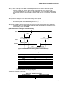
[Data Transmission Timing for Forward Channel]
Data
Byte Data n
Byte Data n+1
Thold
/STROBE
Tsetup
Tnext
Tstrb
BUSY
/ACKNLG
Tready
Tbusy
Treply
Tack
Tnbusy
Figure 1-8. Parallel Interface Timing Chart(Forward Channel)
Table 1-12. Maximum and Minimum Timing for Data Transmission
Parameter
Minimum
tsetup
500ns
thold
500ns
tstb
500ns
tready
0
tbusy
--tt-out*
--tt-in**
--treply
0
tack
500ns
tnbusy
0
tnext
0
* Rise and fall time of every output signals.
** Rise and fall time of every input signals.
Typical time of tack is shown below.
Maximum
--------500ns
120ns
200ns
--10us
-----
Table 1-13. Typical Time of Tack
Parallel I/F mode
High speed
Normal speed
Rev. A
Typical time of tack
2us
4us
1-17
Chapter1 Product Description
[Signal level: TTL compatible (IEEE-1284 level 1 device)]
Table 1-14. Signal Level
Parameter
Minimum
Maximum
Condition
VOH*
--5.5V
VOL*
-0.5V
--IOH*
--0.32mA
VOH = 2.4V
IOL
--12mA
VOL = 0.4V
CO
--50pF
VIH
--2.0V
VIL
0.8V
--IIH
--0.32mA
VIH = 2.0V
IIL
--12mA
VIL = 0.8V
CI
--50pF
*A low logic level on the Logic H signal is 2.0V or less when the printer is powered off and this
signal is equal or exceeding 3.0V when the printer is powered on. The receiver shall provide an
impedance equivalent to 7.5K ohm to ground.
[Data Transmission Timing for Reverse Channel]
The figure below shows timing chart of Parallel Interface Reverse channel.
Virtual Busy Status
Virtual Busy Status
Figure 1-9. Parallel Interface Timing Chart(Reverse Channel)
1.3.3 Prevention Hosts from Data Transfer time-out
Generally, hosts abandon data transfer to peripherals when a peripheral is in the busy state
for dozens of seconds continuously. To prevent hosts this kind of time-out, the printer receives
data very slowly, several bytes per minute, even if the printer is in busy state. This showdown
is started when the rest of the input buffer becomes several hundreds of bytes. Finally, the printer is
in the busy state continuously when the input buffer is full.
1-18
Rev. A
EPSON Stylus Color 400 Service Manual
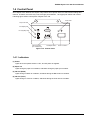
1.4 Control Panel
Since Stylus Color 400 does not require many buttons since printer driver can start various settings and
motions. Therefore, there are only 2 non-lock type push switches, 1 lock type push switch and 4 LEDs.
Following figure shows control panel of Stylus Color 400.
Power LED
Paper Out LED
Ink Out(Bk) LED
Ink Out(CMY) LED
Cleaning Switch
(Ink maintenance)
Load/Eject Switch
Power on Switch
Figure 1-10. Control Panel
1.4.1 Indicators
(1) Power
Lights when the operate switch is “ON”, and AC power is supplied.
(2) Paper out
Lights during the paper-out condition, and blinks during the paper-jam condition.
(3) Ink Out (Black)
Lights during no Black ink condition, and blinks during the Black ink low condition.
(4) Ink Out (Color)
Lights during no Color ink condition, and blinks during the Color ink low condition.
Rev. A
1-19
Chapter1 Product Description
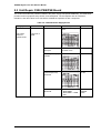
1.4.2 Panel Functions
< Panel Functions >
Table 1-15. Panel Function
Switch
Load/Eject
(Pushing within 2 seconds*)
Function
Loads or Eject the paper.
When carriage is on the Ink Cartridge change position, return carriage
from Ink Cartridge change position.
Load/Eject
(Pushing for 2 seconds*)
Cleaning
(Pushing for 2 seconds*)
Starts the Ink Cartridge change sequence.**
Moves the carriage to cartridge change position.
Stars the Cleaning of head.
In the condition of “Ink Low” or “Ink Out” or “No Ink Cartridge” starts
the Ink Cartridge change sequence.**
Cleaning
When carriage is on the Ink Cartridge change position, return carriage
(Pushing within 2 seconds*)
from Ink Cartridge change position.
Note)
* 3 seconds is required at the User’s manual.
** This function is not available in printing status.
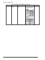
<Panel Functions with Power ON>
Table 1-16. Panel Function with Power On
Switch
Load/Eject
Cleaning
Load/Eject
+
Cleaning
Note)
Function
Stars status printings.**
Changes a Code Page.
Enters the particular settings mode. (Factory use only.)
To enter the particular settings mode, it is necessary to push the
cleaning switch while Paper Out LED is blinking.(It blinks about 3
seconds)
** status printings prints firmware version, ink counter, selected code page and nozzle check
patterns.
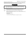
<Maintenance Error Reset >
Table 1-17. Particular Setting Mode
Note)
1-20
Switch
Function
Cleaning
Initialize EEPROM and reset timer IC.
The next page explains the detail procedure of the EEPROM reset.
Rev. A
EPSON Stylus Color 400 Service Manual
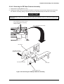
[Maintenance Error Reset Procedure]
You can reset the maintenance error by pressing the cleaning switch after you enter the particular setting
mode(Refer to table 1-15.) There are no function which can be reset the all address in EEPROM on the
Stylus Color 400. Followings are detail procedure of maintenance error reset operation.
WARNING
Stylus Color 400 does not have “All Clear function” for EEPROM like other printers. Therefore,
it is not necessary to replace the new ink cartridge after you perform this reset operation.
Be sure to replace a waste ink pad in the printer enclosure with a new one after you perform this
maintenance error reset operation.
[Step 1]
[Step 2]
Note)
By pushing Load/Eject and Cleaning switches at the same time, turn on the switch.
(By operating this performance, the LED for paper out starts blinking.<3-seconds only>)
Push the cleaning switch while the LED for Paper Out is blinking (3 seconds).
If the printer accepts this function correctly, it returns to the standby mode after the
Maintenance LEDs(both Black and CMY) blink for 1 second. Following shows the lists that will
be cleared by this performance.
1. Maintenance Error Reset
2. Time IC Reset
3. I/F selection (returns to AUTO)
*** The value of ink counter, Bi-D adjustment, VH voltage are not cleared. ***
Rev. A
1-21
Chapter1 Product Description
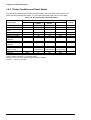
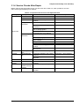
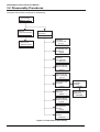
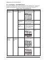
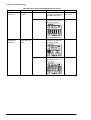
1.4.3 Printer Condition and Panel Status
The table below shows printer condition and panel status. Since this table shows various error
status and also present printer status, you can judge appropriate repair ways from this table.
Table 1-18. Printer Condition and Panel Status
Printer status
Power on condition
Ink sequence
Ink Cartridge change
mode
Data processing
Paper Out
Paper jam condition
No Ink cartridge or Ink
end(black)
Ink level low(black)
No Ink cartridge or Ink
end(color)
Ink level low(color)
Enter EEPROM and
Timer IC reset
Maintenance request
Fatal error
Power
On
Blink
Blink
Indicators
Ink Out
Ink Out
(Black)
(Color)
-------------
Paper Out
Priority
-------
9
6
5
Blink
-------
----Off
On
----Off
---
--On
Blink
---
8
4
3
7
-----
Blink
---
--On
-----
7
7
----Blink
Blink
--Blink
--On
On
On
(1 second only) (1 second only) (1 second only)
Blink
Blink
Blink
On
On
Blink
7
-2
1
Note1*): Refer to section 1.3.3 for error status.
Note2*): It does not mean that all address would be cleared.
Note3*): -- means no changes.
1-22
Rev. A
EPSON Stylus Color 400 Service Manual
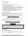
1.5 Error Status
When following status occur, the printer goes to the error status and stops taking data, setting
the /ERROR signal in the interface as “Low”, and Busy signal as “High”. At this time, the printer
goes to non printable status. Refer to section 1.4.3 for more details of LED Panel indicators during
the various error status.
1.5.1 Ink Out
When the printer runs out the most part of the ink of any one color, it warns ink-low and keeps printing.
When the printer runs out the whole ink of any one color, it stops printing and indicates ink-out error.
User is requested to install a new ink-cartridge in this state. A ink-cartridge once taken out should
never be used again. Re-installation of the cartridge not filled fully upsets the ink level detection and
may cause a serious problem in the print head as a result.
WARNING
Never use the ink cartridge once taken out.
Following explains above warning sign.
[Step 1]
After the cartridge is once taken out, bubbles come in from the ink supply hole located at
the top of cartridge and are absorbed into the head during printing performance.
Therefore, the head will be unable to discharge the ink properly. Also, inevitable
entering of bubbles when installing a new ink cartridge can be absorbed to ink itself since
the ink itself in the cartridge is deaerated during the production process.
However, this absorbing ability can last only about one hour after the cartridge is installed.
[Step 2]
Even after the bubble absorbing ability described above stops, there is no worry about
entering bubbles as long as the ink cartridge is being installed to the printer.
However, if the ink cartridge which does not have absorbing ability any more is once
removed from the printer, new coming bubbles into the cartridge will never disappear
naturally. These bubbles may cause not only printing malfunction but also thickening ink.
This thickened ink goes into the head and clogs ink path in the head or nozzle and may
cause serious head damage.
[Step 3]
As standard specification for Stylus Color 400, ink consumption counter is reset when
the ink cartridge is removed. If an ink cartridge is removed and re-installed unnecessarily
the value on the ink consumption monitor which the user can check will be wrong and
printer may keep printing even though the ink cartridge is installed empty.
This may cause head damage.
1.5.2 Paper Out
When printer fails to load a sheet after power on operation including timer-cleaning is done
and Load/Eject button on the FF command or operation panel is pressed, it goes paper out error.
1.5.3 Paper Jam
When printer fails to eject a sheet even after feeding motion is completed or Load/Eject button on
the FF command or operation panel is pressed, it goes paper jam error.
Rev. A
1-23
Chapter1 Product Description
1.5.4 No Ink-Cartridge
Following reasons can be the causes when printer goes this error mode.
1)
When the printer is turned on for the first time.
(This is a normal error state and it returns to the normal state after installing an ink cartridge
according to the ink cartridge exchange operation.)
2) Ink cartridge exchange operation is done correctly.
After the position of carriage is moved by exchange operation, if the cleaning switch is pushed without
installing ink cartridge or if the carriage returns to the home-position automatically without doing any
operation, it is considered as handling mistake. However, it returns to normal state by performing
ink exchange operation again and installing cartridge correctly.
3) If “No ink-cartridge error” appears even after the ink cartridge is installed, the printer must be
something wrong and around the sensor area in the carriage need to be repaired.
4) If sometimes printer can print normally but also sometimes “No ink-cartridge error” appears, the
printer must be something wrong. (Same reason as 3) above)
1.5.5 Maintenance Request
When the total quantity of ink wasted through the cleanings and flushing reaches to the limit, printer
indicates this error and stops. The absorber in the printer enclosure is needed to be replaced with
new one by a service person.
The ink quantity that is absorbed by the absorber (waste ink pad) is monitored by the software counter as
“total ink counter”. This counter is added by point system and absorber’s maximum ability is set at
the following reference value.
✳29500 X 0.0102 ml = Approximately 301 ml
1-point = 0.0102 ml (the value which is multiplied evaporating rate and 1-dot ink weight
0.02 ml)
29500 = Maximum point number (Maintenance error threshold)
However, considering dispersion of ink absorbing quantity and the number of using nozzles, ink total
value is calculated by the following formula.
✳301 X 1.1 ÷ 63% = 526 ml (but up to 532ml can be retained)
WARNING
When you perform self- test after completing repairs, it is possible to check the present value of total
ink counter and ink discharge conditions from all nozzles by performing status printing in the built-in
function. Therefore, make sure that the printer has enough value of total ink counter (if the number is
close to 29500 or not). If there is not enough value, the service man is required to judge if it is
necessary to clear EEPROM after replacing the absorber (waste ink pad) or not. Refer to section 1.4.2
if you need to perform EEPROM Clear.
1.5.6 Fatal Errors
When printer detects fatal errors such as carriage control error or CG access error, it goes to this
error mode. Refer to followings for each error.
1) Carriage control Error : Parallel adjustment malfunction, Home-position malfunction, Timing
belt tension malfunction, shortage of lubricant on the carriage guide shaft, etc.
2) CG Access Error
: Short circuit, etc.
1-24
Rev. A
EPSON Stylus Color 400 Service Manual
1.6 Printer Initialization
Stylus Color 400 has three kinds of initialization methods. Following explains each initialization.
[1.Power-on initialization]
This printer is initialized when turning the printer power on, or printer recognized the cold-reset
command (remote RS command).
When printer is initialized, following action is performed.
(a) Initializes printer mechanism.
(b) Clears input data buffer.
(c) Clears print buffer.
(d) Sets default values.
[2.Operator initialization]
This printer is initialized when turning the printer power on again within 10 seconds from last
power off, or printer recognize the /INIT signal (negative pulse) of parallel interface.
When printer is initialized, following action is performed.
(a) Cap the printer head.
(b) Eject a paper.
(c) Clears input data buffer.
(d) Clears print buffer.
(e) Sets default values.
[3. Software initialization]
The ESC@ command also initialize the printer.
When printer is initialized, following action is performed.
(a) Clears print buffer.
(b) Sets default values.
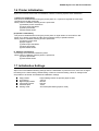
1.7 Initialization Settings
Stylus Color 400 initializes following settings when the initialization is performed. Also, if the user changes
the settings in the Panel setting, Default setting or Remote command setting, values or settings which
are possible to be stored are initialized as initialization settings.
Rev. A
Page position
Line spacing
Right margin position
Left margin position
Character pitch
Printing mode
: Page heading location as present paper location
: 1/6 inch
: 80 lines
: first line
: 10CPI
: Text mode (Not Raster graphics mode)
1-25
Chapter1 Product Description
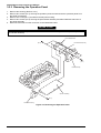
1.8 Main Components
Stylus Color 400 has following major units. Also, it is one of the major characteristics that the bottom of
the Printer mechanism plays the role as Lower case at the same time. Each units from 2) to 4) are
simply explained as following.
1) Upper case
2) Printer Mechanism
3) C206 Main control board
4) C206 PSB/PSE(Power Supply Board)
5) C206 PNL(Panel Board)
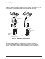
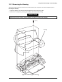
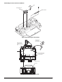
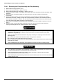
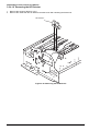
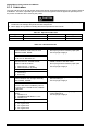
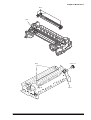
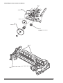
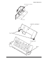
1.8.1 Printer Mechanism
Unlike EPSON’s previous ink jet printer mechanisms, one of the major characteristics of Stylus Color
400 is that the printer has no Engage/Dis-Engage mechanism in order to change over pump mechanism
and paper feeding mechanism. In stead, however, this change-over control is done by the distinction
between turning direction of PF/Pump motor and position of present carriage unit. Also, another major
characteristic is that print head is changed to be one unit combined with black and CMY.
Nozzle configuration for black is 64 nozzles (each line has 90-dpi and between #1-#2 has 180dpi).
On the other hand, CMY nozzle has 21 nozzles(90dpi) for each color. Following figure shows
exterior of mechanism.
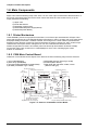
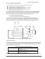
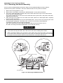
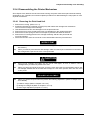
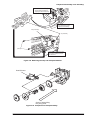
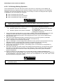
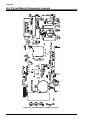
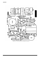
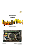
1.8.2 C206 Main Control Board
C206 main control board controls Stylus Color 400 and consists of following major electric elements.
1) CPU (TMP95C061F)
2) Gate Array (E05B44BA)
3) Program ROM (EEPROM or MASK ROM)
4) D-RAM (1CAS/2WE Type: 1M-bit)
5) EEPROM (3strings Serial Type:1K-bit)
6) LB1845 (Motor Driver)
7) With Heat Sink transistor A1469, C3746
(MACH head type)
PF Motor Driver(IC15)
CN10
(Pwer Supply)
Carriage Motor Driver(IC14)
CN1(Parallel I/F Connector)
CN2(RS422 Serial I/F)
Transceiver for
Serial I/F(IC16)
Battery for
timer IC
ASIC E05B44(IC2)
CN6(CR Motor)
CN7(PF Motor)
CN3(Panel I/F)
1K-bit EEPROM(IC11)
CPU TMP95C061
CN5(CRHP Sensor)
Reset for Power
(IC1)
CN4(PE Sensor)
(IC9)
Dinamic RAM(IC4) CN11(ASF phase Sensor)
Reset for Logic
(IC8)
Program ROM(EP-ROM or MASK ROM)
Trapezoidal Wave form Driver(IC6)
CN8(Head Control)
Common Driver Transistor
(Q7,Q9 with Heat Sink)
Figure 1-11. Exterior of C206 Main Control Board
1-26
Rev. A
EPSON Stylus Color 400 Service Manual
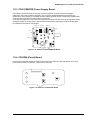
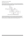
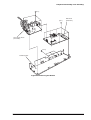
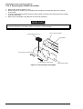
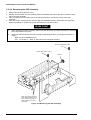
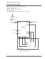
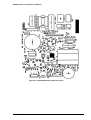
1.8.3 C206 PSB/PSE Power Supply Board
In the electric boards for Stylus Color 400, switching regulator method is used and supplies
stable logic and power voltages constantly. Also, since this C206PSB board has secondly type
switch for its circuit system, it is possible to keep supplying electricity to the C206 main control board
for 30 seconds even after the power switch is turned off.
Using this time difference, even when mis-operation is done by the user such as turning off the power
during the middle of printing work, it prevents thickened ink from attaching around the nozzle plate
by transferring the head to cap position.
Fuse (F1)
Q1 (FET)
Trans (T1)
C51
CN1
CN2
Filter (L1)
C11
PC1
IC51
Figure 1-12. Exterior of C206 PSB/PSE Board
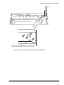
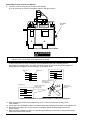
1.8.4 C206PNL(Panel) Board
Panel board (C206 PNL board) is located in the panel case where is in the right bottom of the front
printer and consists of 3 switches, 4 LEDs and 1 connector.
Figure 1-13. Exterior of C206 PNL Board
Rev. A
1-27
Chapter 2
Operating Principles
2.1 OVERVIEW ...............................................................................................................1
2.1.1 Printer Mechanism .................................................................................................................... 1
2.1.1.1 Printing Mechanism ...................................................................................................... 2
2.1.1.1.1 Printing Process ................................................................................................ 3
2.1.1.1.2 Printing Method ................................................................................................. 4
2.1.1.2 Carriage Mechanism .................................................................................................... 7
2.1.1.2.1 Paper Gap Adjust Mechanism ........................................................................ 10
2.1.1.3 Paper Feed Mechanism and Pump Mechanism .........................................................11
2.1.1.4 Ink System.................................................................................................................. 14
2.1.1.4.1 Pump Mechanism ........................................................................................... 15
2.1.1.4.2 Cap Mechanism .............................................................................................. 17
2.2 Electrical Circuit Operating Principles ................................................................18
2.2.1 C206 PSB/PSE Power Supply Board ..................................................................................... 19
2.2.2 C206 MAIN Board..................................................................................................................... 21
2.2.2.1 Reset Circuits ............................................................................................................. 23
2.2.2.2 Sensor Circuits ........................................................................................................... 24
2.2.2.3 EEPROM Control Circuits .......................................................................................... 25
2.2.2.4 Timer Circuit ............................................................................................................... 26
2.2.2.5 DRAM Control ............................................................................................................ 26
2.2.2.6 Print Head Control Circuit........................................................................................... 27
2.2.2.7 PF (Pump) Motor Drive Circuit ................................................................................... 30
2.2.2.8 CR Motor Drive Circuit ............................................................................................... 31
Chapter2 Operating Principles
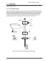
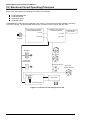
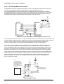
2.1 OVERVIEW
This section describes Printer Mechanism, electric circuit board (C206 PSB/PSE, C206 Main, C206PNL
board) of Stylus Color 400.
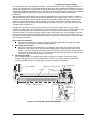
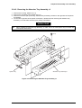
2.1.1 Printer Mechanism
Unlike previous EPSON Ink Jet printers, printer mechanism of Stylus Color 400 does not have exclusive
mechanism to change over paper feeding and Pumping operation. In stead, this control is done by the
turning direction of paper feed/pump motor and position of carriage at that time. Also, unlike previous print
heads, print head of this printer became one unit combined with black and CMY head. Black head has
64 nozzles, 180 dpi(vertical direction) and CMY head has 21 nozzles, 90 dpi (vertical direction). Also,
since these print head is driven by frequency 14.4Khz, this printer can print double resolution(1440
dpi/100-dpi) than Stylus Color. Following figure2-1 shows outline of printer mechanism.
Carriage Unit
(Prinr Head Unit)
Platen Drive Mechanism
Timing Belt
Paper Pickup Mechanism
Paper Pick Up
Trigger Lever
Pumping Position
Pump Drive Mechanism
Paper Feed Motor
Carriage Motor
Figure 2-1. Stylus Color 400 Printer Mechanism Block Diagram
Rev.A
2-1
EPSON Stylus Color 400 Service Manual
As major printer mechanisms in the figure 2-1, there are four major mechanisms as they are listed below.
1) Printing mechanism 2) Carriage unit 3) Paper pick up mechanism 4) Pump drive mechanism
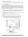
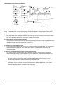
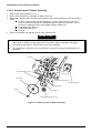
2.1.1.1 Printing Mechanism
Basic principles of the print head which plays major role of printing mechanism is the same as previous
models; on demand type MACH head method, but there is some difference in the resolution. (Refer to
figure1-1) Also, unlike Stylus Color IIs, 820, 200 automatic correction type, in order to fix the dispersion of
mufti layer piezo electric element which is used for driving each nozzles, it is necessary to input the VH
value written on the side of print head by using exclusive program when you replace print head, control
board, or the printer mechanism.(However, there are no resistor array to decide the VH voltage on the
main control board.) Following explains print head.
PZT
PZT is an abbreviation of Piezo Electric Element. Print signal from C206 board is sent through the
driver board on the print head unit and to the PZT. Then, the PZT pushes the top cavity which has
ink stored, and make the ink discharge from each nozzle located on the nozzle plate.
Cavity Set
Ink which is absorbed from ink cartridge go through the filter and will be stored temporarily in this
tank, which is called “cavity” until PZT is driven.
Nozzle Plate
The board with nozzle holes on the printer head surface is called Nozzle Plate.
Filter
When the ink cartridge is installed, if any dirt or dust around the cartridge needles are
absorbed into the head inside, there is a great possibility of causing nozzle clog and
disturbance of ink flow and finally causing alignment failure and dot-missing. In order to
prevent this, filter is set at cartridge needle below and ink is once filtered here.
Printhead driver board
Ink Cartridge Sensor
Actuator
Cartridge needle
(Ink Cartridge)
Filter
PZT
Cavity set
Ink Supply Tube
Nozzle Plate
Figure 2-2. Print Head Sectional Drawing
2-2
Rev.A
Chapter2 Operating Principles
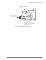
2.1.1.1.1 Printing Process
Following figures indicate the sectional drawing of normal state and ejecting state of the print head.
(1) Normal State:
When the print signal is not output, PTZ also does not move in the waiting state(normal state).
Ink Course
PZT
Nozzle
Cavity
Nozzle Plate
Figure 2-3. Print Head Normal State
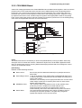
(2) Ejecting State:
When the print signal is output from the C206 main board, IC(IR2C72C:Nozzle Selector) located
on the Print head unit latches the data once by 1-byte unit. Appropriate PZT latched by nozzle
selector is pushed into the cavity by applying common voltage from the C206 main board.
By this operation, ink that is stored in the cavity pops out from nozzles.
Figure 2-4. Print Head Ejecting State
Rev.A
2-3
EPSON Stylus Color 400 Service Manual
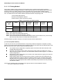
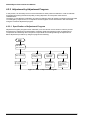
2.1.1.1.2 Printing Method
This section explains printing method of actual printing such as printing text at various resolution
select/printing mode and graphics printing. In order to prevent white or color banding which are peculiar
problem of ink-jet, new Micro-Weave functions are added to the previous Micro-Weave function.
The number of nozzles and printing mode according to the selected resolution are used separately by a
user. The table below shows relation between selected resolution and printing mode.
1) Full Overlap Micro-Weave
2) Part Line Overlap Micro-Weave
3) Micro-Weave: (same as previous control)
Vertical
direction
[dpi]
Printing
mode
360
FOL M/W
M/W
FOL M/W
POL M/W
720
Note1:
Note2:
Note3:
Note4:
Table 2-1. Resolution and Printing mode
Paper feed
Forward
Non
pitch
OverlapOverlap[inch]
Nozzle
Nozzle
15/360
31/360
15/720
29/720
#16∼#30
--#16∼#30
#30∼#32
--#1∼#31
--#4∼#29
Backward
OverlapNozzle
Not used
Nozzle
#1∼#15
--#1∼#15
#1∼#3
#31∼#32
#32
#31∼#32
---
M/W means Micro-Weave.
FOL means Full Overlap Micro-Weave.
POL means Part line Overlap Micro- Weave.
Forward Overlap-Nozzle and backward Overlap -Nozzle are described in the [1.Full Overlap
Mirco-Weave] and [2.Part line Overlap Micro-Weave] below.
Following explains operation outlines of new Micro-Weave functions listed above.
[1. Full Overlap Micro-Weave]
In order to print one line at horizontal direction, this printing method is designed to complete a printing
pattern by two-pass carriage operation with two different types of dot. When this two different types of dot
pass one same line twice, it does not print the same dot twice.
The nozzles whose configuration completely match to the black and CMY nozzle are used.
(Usually Micro-Weave type)
Therefore, all nozzles in case of CMY nozzle and #1∼#63 nozzles in the B2 line in case of
black head are its objects. (B1 line is not used at Micro-Weave. Refer to figure1-1 for detail of
nozzle configuration.)
Out of these 4 color nozzle objects, the number of all nozzles which are going to be used are
divided equally into 2 groups.
Paper feeding will be done as many as each number of nozzles which are divided into two
groups and the same number of dots.(for example, if there are two 10-nozzle groups during
360-dpi printing at longitudinal direction, paper feeding of 10/360-inch becomes available.)
At this time, two groups perform Micro-Weave individually and particular lines are passed by
two different nozzles.
Note1) These nozzles which are divided into two groups must be set and divided in order to
be a pair of odd and even number.
2-4
Rev.A
Note2)
Chapter2 Operating Principles
Two groups which are divided according to each elements will be divided either even dot or
odd dot when particular lines(level direction line) are formed and eventually, these lines will be
completed at selected resolution. Following is a conceptual figure when full overlap microweave orms a particular line.
Condition: 360-dpi printing
Nozzle:
Total 10 nozzle/each color
Nozzle No.#9
Nozzle No.#4
Particular line(Completed line)
360-dpi
Figure 2-5. Full Overlap Micro-Weave
Note 3)
The way firmware decides which nozzle becomes even dot or odd dot is determined
as it is described below.
If the line which is about to be printed is even line:
First dot prints odd dot lines and 2nd dot prints even dot lines.
If the line which is about to be printed is odd line:
1st dot prints even dot lines and 2nd dot prints odd dot lines. Eventually, horizontal resolution
will be the same resolution as selected one.
[2.Part Line Overlap Micro-Weave]
This printing method is to perform Micro-Weave printing, overlapping a part of nozzles which are
used for printing. As a result, a part of raster which is overlapped consists of different browse with
different nozzles. The figure below shows 1-line Overlap at 5-dot sending as an example with
explanation on the next page.
Pass1
#1
#2
#3
#4
#5
#6
Note1: The paper feed pitch is 5/360-dpi in this figure.
Note2: Mark of
and
mean overlap nozzle.
2
3
4
5
Raster 1
6
Raster 10
7
8
9
10
11
Figure 2-6. Part line Overlap Micro-Weave
Rev.A
2-5
EPSON Stylus Color 400 Service Manual
The difference between Full-Overlap Micro-Weave and Part line Overlap Micro-Weave are following;
Full-Overlap Micro-Weave:
Printing is performed, judging if nozzles are even or odd dot by 2 different dots with all
different rasters.
Part line Overlap Micro-Weave:
After particular nozzles(only#1, and #6 in the figure2-7) are determined as overlap nozzles,
even or odd dot will be determined like Full-overlap Micro-Weave does.
(Forward Overlap Nozzle is determined as even and backward nozzle is odd.)
Also, nozzles other than particular nozzles can print at even and odd dot just by one
nozzle.
1) Overlap Nozzle
2) Nozzle other than Overlap nozzle
: Head drive frequency is driven half of the ordinal one like 2)
below.
: Head drive frequency is twice as much as overlap nozzle.
Usually, the firmware changes over automatically these full overlap Micro-Weave, Part line Overlap
Micro-Weave, and ordinal Micro-weave according to the selection of resolution. Also, when these three
printing modes are performed by the Stylus Color 400, the printer performs top and bottom margin
process in order to control the overprinting volume as little as possible.
2-6
Rev.A
Chapter2 Operating Principles
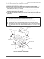
2.1.1.2 Carriage Mechanism
Carriage mechanism is to drive the carriage with print head mounted from left to right or vice versa.
The carriage drive motor in this printer is a 4-phase, 200-pole, stepping motor and is driven by
1-2phase, 2-2phase and W1-2phase drive method. This stepping motor allows the carriage to
move freely to the particular positions which is necessary for various operation, such as paper feeding,
ink absorbing, flashing, ink exchange and cleaning operations. The tables below shows carriage motor
specifications and motor controls at each mode.
Table 2-2. Carriage Motor Specification
Item
Description
Motor type
4-phase/200-pole Stepping motor
Drive voltage Range
42VDC ± 5%
Internal coil resistance
7.8 Ohms ± 10%(per phase under 25 °C
environment)
Driving speed(frequency) range[csp(pps)]
5(60)∼340(4080)
Control method
Bi-Pola Drive
Mode
High speed skip
Printing(Normal)
Printing(SLQ)
Capping
Wiping
Cap(valve release)
Withdrawal of cap
Table 2-3. Motor Control at Each Mode
Driving speed Drive frequency
Drive method
[CSP]
[PPS]
340
4080
W1-2, 2-2,1-2phase drive*
200
2400
W1-2phase drive
100
1200
W1-2phase drive
80
960
W1-2phase drive
40
480
W1-2phase drive
20
240
W1-2phase drive
5
60
W1-2phase drive
*Note 1): The reason why plural drive methods exist is that following some sequences described below
exist in the each mode and stable carriage operation and printing are performed individually
by different drive methods. This drive method is especially necessary for high speed skip.
Acceleration 1 mode → Acceleration 2 mode → Deceleration 1 mode → Deceleration 2 mode
A
/A
C206 MAIN Board
Connecter CN6
Rotor
B
/B
Figure 2-7. CR(PF) Motor Internal Block Diagram
Rev.A
2-7
EPSON Stylus Color 400 Service Manual
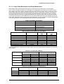
The table below shows W1-2 phase drive sequence at each steps when the rotor of carriage motor
makes one rotation. In the Stylus Color 400, in addition to a function that printing is performed with W1-2
drive phase, high speed skip mode which is a function to skip over the blank from the end of the printing
data to the next data starting point with high seed can be also performed by 2-2 and 1-2 phase drive.
W1-2 phase requires 4 times as much steps as 2-2 phase drive, calculating 2-2 phase as standard.
By using this method, it becomes possible to supply constant stable torque to the motor. As a result, it
also became difficult to be influenced by vibration from the printer mechanism during printing.
Table 2-4. Motor Drive Sequence(W1-2 phase drive)
Phase A
Phase B
Sequence
Number
0
1
2
3
4
5
6
7
8
9
10
11
12
13
14
15
Phase a
10a
l1a
0
0
X
1
1
1
1
1
1
1
X
0
0
0
0
0
1
0
1
0
1
0
0
0
1
0
1
0
1
0
0
0
0
1
1
1
0
0
0
0
0
1
1
1
0
0
0
0
Current
Duty
+2/3
+1/3
0
-1/3
-2/3
-1
-1
-1
-2/3
-1/3
0
+1/3
+2/3
+1
+1
+1
Phase b
10b
l1b
0
0
0
0
0
X
1
1
1
1
1
1
1
1
X
0
1
0
0
0
1
0
1
0
1
0
0
0
1
0
1
0
0
0
0
0
0
1
1
1
0
0
0
0
0
1
1
1
Current
Duty
+2/3
+1
+1
+1
+2/3
+1/3
0
-1/3
-2/3
-1
-1
-1
-2/3
-1/3
0
+2/3
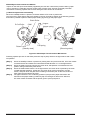
This W1-2 phase drive (or 2W1-2 phase drive) is called Micro-step and is attached with so called
2/3 • Vref or 1/3 • Vref factor, compared with drive current value (Vref100%) which is supplied at 2-2phase
drive. This Micro-Step allows the rotor to have delicate rotation. In the 2-2 phase drive method, it is usually
required to take 4-step sequence in order to rotate the rotor once. However, in case of W1-2 phase, it is
required to take 16-step sequence(in the table 2-4, sequence 0∼15) which is 4 times more than 2-2 phase
method to do that. Also, in case of 2W1-2 phase drive which can be seen in the Stylus Color etc., it takes
2-step to rotate the rotor once. The table below shows relation of rotation direction of rotor and carriage
proceeding direction.
Table 2-5. Relationship Between Rotor Direction and Carriage Operation
Carriage proceeding
Rotation direction of
Drive method
Proceeding order of
direction
Rotor
sequence
HP→80 column direction Looking from rotor output 2-2, 1-2, W1-2 phase
Sequence No.0→15
side, clockwise direction
80 column→HP direction Looking from rotor output 2-2, 1-2, W1-2 phase
Sequence No.15→0
side, counterclockwise
direction
2-8
Rev.A
Chapter2 Operating Principles
The figure below shows the carriage mechanism. The print head as a core of the printing mechanism is
stored in the carriage unit. This print head keeps the tilt of print head in flexible and adjustable structure by
moving the adjustment lever up and down by the tilt adjustment mechanism. (Refer to chapter 4 for more
details) Also, parallelism adjustment lever is mounted on the left and right side of carriage guide shaft and
it adjusts parallelism degree between platen and shaft when this shaft is installed to the printer
mechanism.
After this adjustment is completed and operate PG adjustment lever, it becomes possible to change the
space between the platen surface and the print head surface into 2 phases; either 1.1mm to 1.8mm. It is
possible to vary the space between platen surface and print head by rotating the axis of carriage guide
shaft which itself is decentralized, with the operation of PG lever. This is the mechanism that user can
adjust the appropriate PG value by himself according to the paper thickness or any other environmental
conditions such as paper curl.
Carriage lock mechanism is to prevent the carriage from being left at uncap position for a long time
because of vibration during the printer transport or mishandling by the users. If the carriage is left at uncap
position and uncap state of the print head for long time, an ink on the print head surface gradually
becomes viscosity. As a result, the nozzle will be unable to discharge an ink. To make matters worse, the
holes(crater) of nozzle may be completely clogged by the viscosity ink and it may not be able to return to
the normal condition just by cleaning operation. In order to prevent this, printer goes to carriage lock state
at the following conditions.
After Power OFF operation:
If the power is turned off on the way of printing or any other performance, carriage lock will be
performed in the end after completing initialize operation.
After power ON operation:
After power is turned on and automatic P-On Cleaning is performed, then carriage lock will be
performed. P-On Cleaning is an automatic head cleaning that is performed when the power is
turned on. The timer IC always calculates printer’s power OFF time by the power of lithium battery
mounted on the C206 main board. P-on cleaning function automatically selects the cleaning level
according to the time which the printer is not in used.
After Eject the paper:
After Load/Eject button is pressed and the paper is ejected, if the data is not input, the printer
performs carriage lock and goes to standby state. However, if the paper is loaded to the printer
inside by Load/Eject button, the printer does not perform carriage lock operation.
Paper Feed Motor
Carriage home position Sensor
PF Roller
Eject Roller
Paper guide(Front)
Carriage Motor
Timing Belt
Carriage Unit
Front Side
Rear Side
Parallelism
Adjust Lever
Fixing Bush
Carriage
Guide Shaft
Figure 2-8. Carriage Mechanism Top (Viewing)
Rev.A
2-9
EPSON Stylus Color 400 Service Manual
2.1.1.2.1 Paper Gap Adjust Mechanism
This mechanism can be set by the users and can prevent various problems related to low image density
or print with any dirt by changing the positions of PG lever according to the paper types.
Paper
Normal paper,
Coated paper
Envelopes
Table 2-6. Platen Gap Adjust Lever Setting
Lever position
PG adjustment value
Front
0 mm
(1.1mm between head and platen)
Rear
0.9mm
(2.0mm between head and platen)
It is a major premise that parallel adjustment is done correctly for the space between head and platen
(PG adjustment value above) which can be changed by platen gap adjustment.
Parallel adjustment should be done when the serviceman mounts the carriage guide shaft on the printer
mechanism during the production process or repair service. In the adjustment, the space between
parallel adjustment lever and gage should be 1.04 mm.
2-10
Rev.A
Chapter2 Operating Principles
2.1.1.3 Paper Feed Mechanism and Pump Mechanism
Mechanisms that send the paper in the hopper to inside the printer and perform constant paper
feed in order to perform printing on the sent paper are called paper feed mechanism as generic name.
In the Stylus Color 400, 4-phase, 200-pole hybrid type pulse motor is used in the PF motor as a motive
power of the paper mechanism and driving is done at 2-2 and 1-2 phase drive method. This motor is
not only used as a power source for paper feed mechanism but also used as power source of pump
mechanism which is necessary for print head cleaning. By using this pulse motor, it becomes possible
to use high speed driver or intermittent drive for the various paper feeds and pump operations such as
paper feed, slight paper feed, high and low speed absorption of pump operations. Following tables(Table
2-7 and 2-8) show PF motor specifications and control method at each mode.
Table 2-7. PF Motor Specification
Item
Description
Motor type
4-phase/200-pole Stepping motor
Drive voltage
42VDC ± 5%
Coil Resistance
7.8 Ohms ± 10%(per 1 phase under
25°C environment)
Drive frequency [csp(pps)]
400-4320Hz
Control method
Bi-Pola Drive
Table 2-8. Motor Control Method at Each Mode
Drive Method
Drive Frequency
[Hz]
Paper feed A
2-2 phase
4320
Slight paper feed
1-2 phase
400
Slight paper feed
1-2 phase
2400
High speed attraction of pump
2-2 phase
4100
Low speed attraction of pump
1-2 phase
1800
Low speed paper feed
1-2 phase
1200
Paper feed B
2-2 phase
3400
Paper feed C
1-2 phase
4000
Ordinal absorption of pump
1-2 phase
4100
Mode
Pulse Space
(µs)
231
2500
417
243
555
833
294
250
243
Following tables show 1-2phase drive method at PF motor drive and each drive sequence at 2-2phase
drive method.
Table 2-9. 1-2 Phase Drive Method
Clockwise
Counter clockwise
Step No.
1
2
3
4
Step No.
1
2
3
4
Rev.A
Phase A
+2/3
0
-2/3
-1
-2/3
0
+2/3
+1
Phase B
+2/3
+1
+2/3
0
-2/3
-1
-2/3
0
Phase A
+2/3
+1
+2/3
0
-2/3
-1
-2/3
0
Phase B
+2/3
0
-2/3
-1
-2/3
0
+2/3
+1
Table 2-10. Drive Sequence at 2-2 Phase Drive
Clockwise(CW)
Counter clockwise(CCW)
A
+2/3
-2/3
-2/3
+2/3
B
+2/3
+2/3
-2/3
-2/3
A
+2/3
+2/3
-2/3
-2/3
B
+2/3
-2/3
-2/3
+2/3
2-11
EPSON Stylus Color 400 Service Manual
Papers on the ASF (auto-sheet-feeder) supplied by the user are carried to the printer inside by paper
pick up sequence. Unlike the previous models, ASF of Stylus Color 400 has mufti feed prevention
mechanism. Following explains this function and figure below shows its mechanism.
[1. Multi feed prevention mechanism]
When the Load/Eject button is pressed, reversed rotation of PF motor is performed.
The return lever resets papers which are already in the out of stand by position in the stand by position
and make it possible to perform stable paper feeding by picking up the paper again.
Pintch Roller
D-Cut Roller
CAM
Hopper
Hopper spring
2)
1)
2)
Pad spring
Return Lever
[Standby state]
[Returning state]
Figure 2-9. Multi Paper Feed Prevention Mechanism
Following explains process of multi feed prevention step by step. Refer to the figure above and confirm
its operation.
[Step 1]
[Step 2]
[Step 3]
[Step 4]
2-12
When the load/Eject switch is pressed or printing order is input from the PC, PF motor rotates
counterclockwise and makes the CAM rotate towards direction of 1 in the figure above.
When the CAM covers the notch by the return lever, that position is considered as home
position, being monitored by ASF sensor.
When the CAM rotates toward 1 in the figure above, the return lever is pushed by the notch
of CAM and falls towards 2. At this time, the return lever moves to direction 3 by this
motion, and push down the pad which is waiting in the below part. At this time, friction of
pinch roller and pad will be canceled.
The papers which are out of stand by position by the previous paper feed motion are
returned to the paper stand by position by flip over strength of return lever. After this,
PF motor rotates clockwise and the printer goes to pick up sequence.
Rev.A
Chapter2 Operating Principles
In the paper pick up mechanism of Stylus Color 400, same mechanism as Stylus Color IIs/820
are applied. This mechanism changes adjoined lines of gear by colliding trigger lever with carriage unit
and convey the motive power on the platen to the ASF side(paper roller). The figure below
shows mechanism with explanation.
[2. Paper pick up mechanism]
When the Load/Eject switch is pressed or printing order is input, the carriage unit moves until
the left edge and collides with paper pick up trigger lever. When the carriage collides with this trigger
level, a planetary gear located on the same axis is also pushed at the same time and conveys
the motive power on the platen to the adjoined gear line side for ASF drive.
Paper Pick Up
Trigger Lever
ASF Roller Drive Gear
Eject Roller Drive Gear
Planetary Gear
Eject Roller
Transmission Gear
PF Motor Pinion Gear
ASF Roller Transmission Gear
Platen Roller Transmission Gear
Platen Roller Drive Gear
Figure 2-10. Paper Pick Up Mechanism
[3. Paper feed mechanism]
After papers in the ASF receive controls from pick up and multi feed prevention mechanism, they are
sent to the printer inside. The papers picked up by paper roller in the ASF goes to between platen
and roller support. Also, the eject roller pushes out the paper completely until the end and the roller
support drops the paper in the eject tray. The eject roller is driven with an eject paper notched roller as
pair where is located on the paper eject roller. Paper eject notched roller solves the deflection of paper
that is in the between platen eject notched roller and paper eject roller and always keep a certain space
between print head and paper surface. The figure below shows the paper feed mechanism.
Paper
Eject Notched Roller
Support Roller
Eject Roller
PF Roller
Figure 2-11. Paper Feed Mechanism
Rev.A
2-13
EPSON Stylus Color 400 Service Manual
2.1.1.4 Ink System
Ink system mechanism consists of 1)cap mechanism, 2)pump mechanism, 3)carriage lock
mechanism, 4)waste ink absorber and 5)ink sequence. Out of these mechanism, from 1) to 4)
are physical mechanism and parts which are mounted on the printer mechanism and 5) ink
sequence is performed automatically by firmware. Also, unlike previous models, since
Stylus Color 400 has no engage/disengage mechanism to change over pump mechanism and
paper feed mechanism, it is one of the major characteristics that pump and platen are always
at work whenever the PF motor is driven. The figure below shows head positions when the ink
system and various ink sequence are performed.
Platen Drive Gear
Eject Roller Drive Gear
Eject Roller
Trasmission Gear
Head Cleaner
Carriage Lock
PF(Pump) Motor Pinion
Pump Roller
Cap Unit
Figure 2-12.Ink System Mechanism
CRHP
2975 dot
H
G
F
E
D
C
B
A
Figure2-13. Major Ink Sequence Position on the Carriage Mechanism
2-14
Rev.A
Chapter2 Operating Principles
2.1.1.4.1 Pump Mechanism
In the Stylus Color 400, there is no switch or mechanism to change over the pump/paper feed
mechanism. Therefore, whenever the paper feed/pump motor rotate, pump drive roller in the pump unit
inside rotates. However, ink absorption/non ink absorption are separated by the roller rotational direction.
Also, even if the pump driver rotates toward ink absorption and the carriage position is in the false
absorption position, only driving in the pump mechanism is performed and actual ink attraction is not
done. The figure below shows process of conveying motive power to the pump drive roller.
Gear A
Axis of Paper Eject Roller
Gear B
Gear C
Actually, these parts
are one unit.
Compression
Spring
Pump Drive Roller
Figure 2-14. Pump Mechanism Power Transmission Process
The process of conveying the motive power to the paper eject roller by rotating the pinion of PF motor
is descried in figure 2-12. This motive power is conveyed to the Gear C through the Gear B.
In the figure above, although the lever in order to drive Gear C, carriage lock, head cleaner mechanism
is shown separately, it is constructed as one unit. Since the engagement of these two parts depends on
the tension of the compression spring, if the lever is burdened, only Gear C and pump roller rotate and no
more motive power is conveyed to the lever part.
Rev.A
2-15
EPSON Stylus Color 400 Service Manual
The table below shows PF/Pump motor rotational direction and pump system operation.
Table 2-11. Relationship Between Pump Motor Rotation and Pump Operation
PF/Pump motor rotational direction
Pump unit operation
Clockwise(CW)
1)Release from the Pump pressure welding
forward rotation
2)Head cleaner reset
3)Carriage lock reset
Counterclockwise(CCW)
1)Rotation towards pump pressure welding
backward rotation
2)Head cleaner set
3)Carriage lock set
The figure below shows the pump operation at clockwise and counterclockwise rotation.
CW Rotation
Tube pressured
CCW Rotation
Tube released
Figure 2-15. Pump Roller Rotation and it’s Operation
In the ink absorptive operation such as cleaning, flushing and initial ink charge except for printing
operation, ink in the ink cartridge drains to the waste ink absorber(pad) through the cap by the pump unit
drive. In case of printing and flashing drive, ink is popped out by the PZT in the print head, but in case of
absorptive operation such as cleaning and initial ink charge, ink absorption is performed
only by the pump drive without PZT drive after the head surface is adhered to the cap.
The next page explains cap mechanism and relation between printer operation and cap.
2-16
Rev.A
Chapter2 Operating Principles
2.1.1.4.2 Cap Mechanism
In the cap mechanism, in order to prevent ink from being thickened on the head surface, it is controlled
that the head surface stays adherent to the rubber frame of the cap surface when the power is off.
The absorber is spread in the cap and can hold a certain amount of ink which is absorbed from the
head without draining it to the waste ink pad. Also, in the bottom of absorber, there are two valves in order
to control adhesion of head and cap surface, and one exit to drain ink to the waste ink pad.
A
B
Flag for Carriage
Ink Eject Valve
Negative pressure
release valve
Valve
Release state
Close state
Flag for frame
Head surface and
cap are adhered
each other.
Actual and false
absorptions.
During cleaning, initial ink
charge, and right flushing.etc.
Ink absorption in
the cap.
During left flushing and paper
feeding,etc.
Figure 2-16. Cap Mechanism Operation Principle
If the carriage is out of HP(in this case, in the printable area or paper feed position), the valves on the
cap mechanism stays in the position A in the figure above and are always closed. In this condition,
the carriage collides with flag, actual ink absorption and slight ink absorption are performed.
Also, by moving the carriage to further right side and colliding the flag for opening the valves with
the frame, negative pressure is released in the state that head surface and cap are adhered. This
makes it possible for ink on the nozzle plate surface to be ready for leaving from the cap in the stable
condition.
Rev.A
2-17
EPSON Stylus Color 400 Service Manual
2.2 Electrical Circuit Operating Principles
Stylus Color 400 contains the following four electric circuit boards.
C206 PSB/PSE board
C206 Main board
Head Driver board
C206 PNL board
C206 PSB/PSE, C206 board are explained in this section. The head drive board is installed in the head
unit on the carriage. The figure below shows major connection of the 3 boards and their roles.
RCC Switching Regulator
(C206 PSB/PSE Board)
+5 V DC
C206 Main Control Board
(C206 Main Board)
+5 V DC
+42 V DC
INK END Sensor
(Firm Wear)
+42 V DC
AC100V
CR Motor
PE Sensor
PF MOTOR
(Pump Motor)
BCO/CCO Sensor
Thermistor
ASF Lever
Position Sensor
Print Head
Head Drive Board
Figure 2-17. Electric Circuit of Stylus Color 400
2-18
Rev.A
Chapter2 Operating Principles
2.2.1 C206 PSB/PSE Power Supply Board
C206 PSB/PSE board is a power supply board with a RCC switching regulator, which generates +42VDC
for drive part and +5VDC for logic part to drive the printer. One of the major characteristic of this board is
that the same secondary switch is used as Stylus Color series printer. By using this switch, the following
difference can be seen as superficial phenomena compared with products applied with primary switch
method, such as Stylus Color IIs, II and Stylus 800/1000 series printer. The table 2-12 below shows
application of voltages generated by C206 PSB/PSE board.
1) Even if the switch is turned off during the middle of printer operation, since the driving
power is turned off after the carriage goes back to the carriage lock position,
the possibility of clogging ink nozzle will be decreased.
2) If the switch is turned off when the papers in the printer are still being carried except for
the papers in the hopper, the same operation mentioned above is performed and the
driving power is turned off after the paper is completely ejected.
Voltages
+42VDC
+5VDC
Table 2-12. Application of DC Voltage
Application
CR Motor
PF/Pump Motor
Head driving power supply
Power supply for logic control
System control signal
Sensor circuit power supply voltage
LED panel drive power supply
Nozzle selector control signal power supply voltage
Figure 2-18 shows block diagram of C206 PSB/PSE board. The process from the input of AC100V to the
output of 42 V DC and 5 V is explained below.
1) Regardless of the state of power switch(On or OFF), the voltage is always applied in the primary
side of the power supply board from the moment or at the state that AC-plug is plugged in.
At this time, F1 plays a role of preventing AC100V from coming into the F1.
L1 and R1-R2 also prevent high harmonic wave noise generated in the RC circuit filter which consist
of C1∼C4 and R1∼R2 from going out, and eliminate the noise from outside here.
2) The AC is full-wave rectified by diode bridge DB1, and converted to
electrolytic capacitor C11.
2 x AC in voltage by smoothing
3) The pressured up direct current makes Q1 On through the starting resistor R31 and starts the primary
side of the circuit.
4) When the primary side is On state, the energy(current) led by the electromagnetic induction through
the trans (T1) does not flow to the secondary side since the diode(D51) on the secondary side
is installed in the opposite direction.
5) When the energy which is charged in the trans is reaching the saturated state, the voltage which
makes the Q1 On becomes weak gradually. At the point that this voltage drops at the
certain voltage, C13 absorbs the current in the opposite direction and Q1 is quickly shut off by
the resulting sharp drop.
6) When the primary side is turned off, the energy charged in the T1 is opened according to the
diode(D51) direction which is installed on the secondary side. Basically, 42 V DC is output
by these circuit operations and the number of T1 spiral coil .
7) +5VDC is generated by pressured down this +42VDC as power supply. IC51 pressures down the
+42VDC and generates precise +5VDC by chopping off the output, forming the standard santooth
wave form by the outer RC integration circuit.
Rev.A
2-19
EPSON Stylus Color 400 Service Manual
DB1
Full Wave
Rectifier circuit
L1,R1-R2
T1
C11
C1-C4
Filter Circuit
Prevention of
current flow
+42VDC
Q1
T
R
A
N
S
Main switching
circuit
Q2,Q3,
F1
D51
Smoothing
circuit
C51
Smoothing
circuit
+5V generation
circuit (IC51)
+42V constant
voltage control
circuit
C84,Q84
Power OFF
Delay circuit
Q31,PC1
ZD81-86,
ZD51
Feedback
circuit
+5VDC
ZD52,87
+42V overvoltage
protection circuit
ZD53
+5V overvoltage
protection circuit
PSO Signal
PC1
Photo coupler
AC100V
Figure 2-18. C206 PSB/PSE Board Block Diagram
The C206 PSB/PSE board has various control circuits to stop output if malfunction on the power supply
board, on the main board or on the duty of printer mechanism happen. Following explains each control
and protection circuits.
1) +42V Line Constant Voltage Control Circuit:
The output level of the +42V line is monitored by a detection circuit consisting of seven Zener diodes.
This circuit prevents voltage from dropping for constant output voltage.
2) +5V Line Over voltage Protection Circuit:
This protection circuit is in the same line as +42V over voltage protection circuit is located. The output
voltage level of the +5V line is monitored by a Zener diode. This circuit shuts down the circuit
operation forcefully when the voltage level exceeds +9V.
3) +42VDC Line Over voltage Circuit:
This circuit is in the same line as +5V line over voltage protection circuit is located. The output level is
monitored by two Zener diodes. If the voltage level exceeds +48VDC, this circuit stops circuit
operation forcefully.
4) +5V Line Constant Voltage/Constant Current Control Circuit:
The output current is monitored by a +5VDC generation switching control IC(IC51), which also
monitors the output voltage. This information is input to the internal comparator and stabilizes +5V
line. Also, operation of the secondary side switch is explained below.
1)
When the power is turned on, Q1 repeats ON/OFF automatically along with the increase and
decrease of energy on the trans coil at the primary side. While the power is being on, PSC
signal is input to the power supply board from the C206 main board.
2)
This signal turns Q84 on and it becomes possible to discharge energy between 8-9 of T1.
At this time, even if the power is turned off, the electrolytic capacitor keeps Q84 on for a while.
By this electrolytic capacitor, output is hold at least 30 seconds even after the power is turned off.
This time helps the printer to complete the P-Off operation.
2-20
Rev.A
Chapter2 Operating Principles
2.2.2 C206 MAIN Board
Various DC voltage generated on the C206 PSB/PSE board is added various signals in order to drive the
printer function on the C206 main board, and the drive of CR/PF(Pump) motor and printing head is
performed. This control board consists of system part and drive part. In the system part, there are
formation and controls of various signals in order to drive the CR/PF(pump) motor, sequence control
by input from the sensor circuit, and also output of signal to select appropriate nozzle for the printing
head. On the other hand, the drive part has constant current drive by the driver IC for the CR/PF(pump)
motor drive and trapezoidal wave form circuit for head drive.
C206 Main Board
PROM4M
(IC3:EPROM)
DRAM Control
TPM 95C061
(IC1:CPU)
M5M411664
(IC4:D-RAM)
E05B44
(IC2: Gate Array)
System
CR/PF Motor Drive
to B
Panel I/F
Head Temperature
Head Common Drive
to A
Centornics I/F
SN75LBC775
(IC16 Transceiver)
Serial I/F
Sensor Circuit
EEPROM (IC11)
Timer (IC5)
From A
H8D2813D
(IC6)
From B
LB1845
(IC14)
From B
LB1845
(IC15)
Print Head
Power
Carriage Motor
PF(Pump) Motor
Figure 2-19. C206 Main Control Board Block Diagram
[CPU]
The C206 main board is controlled by a 16-bit CPU(TMP95C061AF) running at 25Mhz. Gate array
manages most of controls and monitors. Likewise the Stylus Color, the D-RAM is applied for RAM
which is used as work area for receiving data and developing the data and CPU manages its control
such as CE, RAS/CAS controls.
[Gate Array]
E05B44 controls following functions.
Rev.A
Motor control :
Each motor performs data transmission(W1-2 phase) that motives
Micro-Step.
Head voltage control: In the ink jet printers, drive voltage wave form(trapezoidal wave form)
in order to drive PZT is formed in the various shapes according to the
types of the printers.
Therefore, it is necessary to form appropriate drive form for each head.
Head voltage control forms necessary wave form for each control
signals and outputs them.
EEPROM control:
The correction value to eliminate the error of each printers at the
production process is installed in the fixed address of IC.
When the power is turned off, the contents set by users is
written instantly, and is red to the RAM when the power is turned on.
Sensor Data:
The sensor detects information at the various conditions, which is
necessary for the printer operation. The gate array recognizes
signals and changes over to the next control.
2-21
EPSON Stylus Color 400 Service Manual
Timer Data:
The timer IC that uses lithium battery as power source monitors how long
the power is off. When the power is turned on, it is changed to appropriate
cleaning level according to the time that the power is off.
Serial Data:
The gate array receives serial data through the transceiver IC.
Parallel I/F control: With the use of IEEE1284 Nibble mode, it became possible not only to
receive the data from the host but also to return various information which
the printer possesses to the host.
[Common Driver IC]
The trapezoidal wave form circuit for head drive is became to HIC from the previous discreate structure.
Because of this, it is not necessary to adjust the adjustable VR on the board during production process.
Various electric charge/discharge control signals are all processed in the HIC.
[CR/PF Motor Drive Circuit]
Constant current drive is performed by the HIC. Out of this, only CR Motor is controlled for Micro-Step
control and HIC becomes possible to flow the appropriate current value at each steps. (PF Motor has
only 1-2, 2-2phase drive method). Also, bipolar drive is performed on the 4 cables individually. Following
pages explain each major control circuit.
2-22
Rev.A
Chapter2 Operating Principles
2.2.2.1 Reset Circuits
The reset circuit prevents the CPU from running away, which is caused by the unstable voltage in the
logic line during the power ON/OFF operation. Also, this circuit monitors level of power voltage at the over
loading or malfunction on the circuit and manages the printer to operate normally, keeping the damage to
the printer minimum during the abnormal situations. On the C206 main board, 2 ICs are mounted ; IC for
monitoring the voltage level (logic line) and IC for monitoring the voltage level (power line) and both
are monitored by the gate array and CPU.
The figure below shows reset circuit block diagram with explanation on the next page.
+5V
+5V
PST592D
(IC8)
R1
Vout
NRES
Vcc
GND
1
2
3
4
R138
C47
E05B44
(IC2)
TMP95C061
(IC1)
P85
15
10
P84
/RESET
16
174
30
/RESET
/NMI
+5V
+42V
M51955B
(IC9)
R10
2
R6
4
IN
NC8
8
7
VCC
6
OUT
5
NC5
GND
Figure 2-20. Reset Circuit Block Diagram
[PST592(IC8)]
The actual operation of the circuit is to keep outputting Low signal until +5V line goes up to +4.2V
when the power is on, and to cancel the reset signal with output of High signal when the voltage goes up
more than 4.2V.
[M51955(IC9)]
This IC also performs as monitor on the power line same as the reset IC for logic described above.
High/Low is judged at the 33.2V.
[Relation between IC8 and IC9]
Reset signal which is low and output by IC9 is input to the CPU and gate array and system reset operation
is performed. Also, this signal is detected on the IC9(IC for reset monitor, power line) and outputs the
same Low signal towards CPU/NMI terminal by being input to NC5.
Rev.A
2-23
EPSON Stylus Color 400 Service Manual
2.2.2.2 Sensor Circuits
The following sensor circuits are mounted in the Stylus Color 400 and selects appropriate operations
based on the returned information.
ASF Sensor:
(Photo)
An ASF sensor detects the position of return lever when the power is
turned on, and causes the paper to be picked up by the pick up roller
from the normal initial condition. (Refer to section 2.1.1.3 for detail.)
PE Sensor:
(Photo)
A PE sensor determines if there is paper in the printer. Based on the
signal form this sensor, a particular paper edge treatment such as
Micro-weave printing is performed.
HP Sensor:
(Photo)
A HP sensor detects the carriage home position.
It is used for managing printing position and cleaning, etc.
Thermistor Sensor:
A thermistor sensor keeps stable printing quality, changing PZT drive
voltage(VH) slightly according to changes of environmental
temperature.
Cartridge Sensors:
Cartridge sensors are built into the Bk, CMY cartridge on the carriage
unit respectively to determine if the cartridge is installed or not when it
is exchanged or the power is turned on. In case of Stylus Color 400,
the counter is reset at every time the cartridge is removed.
The figure below shows sensor circuit. Out of the data such as EPW with IEEE 1284 Nibble mode
to be returned to the host, the data to indicate ink consumption is calculated and managed by the
counter of the firmware. Therefore, it is omitted here.
TMP95C061
(IC1)
+5V
Vref
AGND
AN0
18
CCO
17
BCO
3
THM
20
2
1
+5V
CN8
CN8
+5V
PEV
GND
3
E05B44
(IC2)
SW8 CCO(198)
+5V
2
HPV
GND
SW7 BCO(200)
SW6 PE(202)
PE
1
HP
SW5 HP(204)
ASFV
SW4 ASF(206)
GND
ASF
Figure 2-21. Sensor Circuit Block Diagram
2-24
Rev.A
3
2
CN4
1
3
2
CN5
1
3
2
1
CN11
Chapter2 Operating Principles
2.2.2.3 EEPROM Control Circuits
The EEPROM of Stylus Color 400 has following contents. Gate array E05B44(IC2) controls operations of
reading data when the power is on and writing data when the power is off.
Ink consumption(Bk, CMY)
CL counter(Various cleaning operations that are previously done are memorized)
Destination information
Information of various adjustment values(Bi-D, VH voltage, etc.)
CPSI pass word
Other various setting values by the user
EEPROM is connected to the Gate array by 4 lines and performs following functions.
The figure below shows EEPROM control circuit.
CS :
CK :
DI :
DO :
Chip selection signal
Data synchronism clock pulse
Data writing line(serial data) at power off.
Data reading line(serial data) at power on.
+5V
93C46(IC11)
8
6
VCC
ORG
5 GND
CS
CK
DI
DO
1
127 ECS E05B44(IC2)
2
128 ECK
3
126 EDO
4
125 EDI
Figure 2-22. EEPROM Circuit Block Diagram
Rev.A
2-25
EPSON Stylus Color 400 Service Manual
2.2.2.4 Timer Circuit
The lithium battery is mounted on the C206 main board and calculates how long the printer is not used.
The timer IC(IC5) starts counting with oscillation motivated by the CR1 using this battery as a power
source. The figure below shows connection of the Timer circuit.
+5V
BAT1
D7
D1
8
2
CR1
3
VDD
1
TCE
122
TIO
/SCK 6
121
TCLK
7
124
TDATA
XOUT
XIN
4 VSS
S-3510ANFJ
(IC5)
E05B44(IC2)
123
CS
SIO
+5V
Figure 2-23. Timer Circuit Block Diagram
The followings explain about operation of this circuit.
When the printer is on, power is supplied to the Timer IC by applying +5V quickly through
the D1.
This power is also used for the power to oscillate the outer CR1. The oscillation wave form is
input to XIN terminal.
Since the oscillation wave form of CR1 is analog wave form, it is processed into the
pulse form in the Timer IC.
When the printer is turned on, the Timer IC outputs power off time as serial data to the gate
array.
Once the printer is turned off, 3VDC of BAT1(lithium battery) is supplied as power source for
he Timer IC through D7.
Since +5V at the power on is higher than +3V of the lithium battery, the power is not being
consumed from the lithium battery.
2.2.2.5 DRAM Control
In the Dynamic RAM control, output and formation of CAS and RAS control signals become necessary
in addition to the output of CS signal. The CPU TMP95C061AF not only controls that but also perform
the output of CS signal of P-ROM. Refresh timing is performed in the CAS Before RAS.
2-26
Rev.A
Chapter2 Operating Principles
2.2.2.6 Print Head Control Circuit
The print head control circuit of Stylus Color 400 has following characteristics.
Common wave form circuit became one HIC.
Slight vibration mode is added.(when the CR motor is accelerating)
High speed drive 14.4Khz (trapezoidal wave form
Big Nozzle configuration (resolution in the vertical direction)90dpi
(However, black nozzle is 2 lines structure)
Also, Stylus Color 400 does not have Micro-dot control as dot shooting control, but there are two types;
Normal-dot and Normal dot-2dot. Normal-dot-2dot was called Dual Firing in the Stylus Color IIs/820.
These setting/change are controlled automatically by setting of the printer driver that is determined
by the user. The followings are required conditions to perform the normal-dot 2-dot.
At the OHP sheet setting (360X360 dpi)
At the ordinary paper and resolution 360X360 dpi setting
The control circuit is considered as 2 divided parts; 1) trapezoidal wave form generation circuit
(common drive circuit) to drive PZT in the head, and 2) Nozzle-selector drive circuit to determine
which nozzle should be used. The Nozzle-Selector is attached to the head unit just like the previous
models. The common drive circuit is sumed as one HIC and mounted on the C206 main board.
+5V
+42V
F1
H8D2813D
(IC6)
VM
VCC
E05B44
(IC2)
CHG
KC1
ND1
ND2
MD1
MD2
DATA
DATA
/STB
CLK
CHG
KC1
ND1
ND2
MD1
MD2
DATA
DATA
/STB
CLK
CTC
DTB
GND1
GND2
19
20
21
CN8
16
17
18
Figure 2-24. Print Head Control Circuit Block Diagram
[Common drive circuit]
The shape of trapezoidal wave form will be different according to the printing operation, slight vibrations at
the non-printing nozzle and waiting condition. However, IC6(H8D2813) generates all wave forms as drive
wave forms by resistance(electric) welding control of common voltage drive control signal that is output
from the IC2(E05B44) in the figure above.
Table 2-13. Specifications of H8D2813 Operation
Item
Contents
Drive Power Voltage
42 ± 5 %
Starts supplying after 5V rises and be stabilized./ Stops
supplying before +5V drops.
2SC3746(for charging), 2SA1469(for discharging)
Final drive element
Off on the both charging and discharging sides.
Operation at the Reset
Supplies drive power source.
This common voltage trapezoidal wave form can be observed anytime after the +5V rises even if there is
printing data or not. (Q7:3-pin,Q9:3-pin and GND on the C206 main board)
Rev.A
2-27
EPSON Stylus Color 400 Service Manual
[Nozzle Selector Drive Circuit]
In order to motivate the print head to carry out printing, it is necessary to transmit the printing data to the
appropriate nozzles, which becomes direct signals to drive PZT. This data transmission is performed
by the serial method, however the data output for each black and CMY head is transmitted by the parallel
method. The figure below shows data transmission circuit.
CN8
VH
COM
NCHG
Gate Array
E05B43(IC2)
CLK
U101
IR2C72C
SI1
SI0(for black)
SI2
SI1(for colr)
SCLK
LAT
THM
LAT
Black Data
Latch
Black Nozzle
XCHG
COM
VHV
Color Data
Latch
Color Nozzle
VD1/2
Figure 2-25. Nozzle Selector Circuit Block Diagram
CLK(Clock) pulse considered as source of serial communication is commonly used for both black and
CMY. The serial data transmits data as 64-Clock unit, synchronizing with this pulse. After the data
transmission of 64-Clock is completed, LAT(Latch) signal is activated and is hold temporarily in the
IR2C72C. At this time, since the number of nozzle for Color head is fewer(21-nozzle) and different from
the ones for black head, 0 is transmitted forcefully for the data for 43 nozzle (64-21=43).
2-28
Rev.A
Chapter2 Operating Principles
After the data transmission by the nozzle selector(IR2C72C) is completed and a certain time passes,
trapezoidal wave form generated by the common drive circuit once sends electric current to the PZT
for the proper nozzles which are determined in the nozzle selector circuit. This motivates PZT and
ejects the ink in the cavity. The figure below shows normal dot data transmission timing in order to form
1 dot.
Figure 2-26. Timing Chart at the Generation of Normal Dot
Rev.A
2-29
EPSON Stylus Color 400 Service Manual
2.2.2.7 PF (Pump) Motor Drive Circuit
IC15(LB1845) is used for driving PF(Pump) motor. In the IC, Bi-pola drive PWM current control type
is performed, making it possible to provide stable current to each phase of motor.
Also, it makes possible to change over the reference voltage as drive current settings by making
3 combinations(100%, 66% and 33%), using 4 current setting ports(input). (Refer to 2.1.1.3 for motor
and details about sequence) However, firmware does not drive Micro-step in the Stylus Color 400.
The figure below shows connection diagram of PF(Pump) motor drive circuit.
+42V
Figure 2-27. Connection Diagram of PF(Pump) Motor Drive Circuit
Unlike using Uni-Pola drive, there is no cable for GND in the motor since Bi-Pola drive is performed in the
PF motor.(Refer to figure2-10 since carriage motor interior connection diagram has the same connection
as the PF motor’s phase connection. This helps to understand the reason why the direction of
current is controlled freely in each phase by the combinations of high/low control signals.
The current control is performed by output port(46∼49 pin) of E05B44(IC2), its outer resistance
circuit and driver IC(LB1845). First, firmware possesses 16 ways of current values as current table
out of combinations made by 5 resistance which are connected to the output ports(46∼49 pin) in the
gate array. On the other hand, signals which are output by combination of these resistance’s on/off
are input in the 26 and 17 pins. HIC is driven at the same standard voltage for each A and B phase.
Actual on/off control to send electricity through the motor is performed by the process that SEN1 and
SEN2 terminals (2 and 13 pin) detect the input signal from the gate array which is monitored by the
interior comparator, confirm the current that actually flew the phase as current value again and
perform the feed back to the on/off. The figure below shows relation between input signal to the
driver IC and motor control.
+42V
Note:
In case of PM motor,
same reference voltage
is input to UDN2917 for
both phase A and B, but
differet reference voltage
is set individually for
phase A and B, in case of
R1
CR motor.
+5V
Ra
R2
R3 R4
Rb
RS
E05B44(IC2)
Gate Array
If feeds back the current
that actually flew in the
coil to the comparator.
It varies load resistance
by the control signal and
changes the ratio of partial
pressure.
UDN2917(IC14,IC15)
Figure 2-28.Motor Drive
2-30
Rev.A
Chapter2 Operating Principles
2.2.2.8 CR Motor Drive Circuit
In the CR motor, the same LB1845(IC15) as the PF motor has is used. In the IC, Bi-pola drive PWM
current control type is performed, making it possible to provide stable current to each phase of motor.
Also, it makes possible to change over the reference voltage as drive current settings by making
3 combinations(100%, 66% and 33%), using 4 current setting ports(input). (Refer to 2.1.1.3 for motor
and details about sequence) However, firmware performs Micro-step driving in the Stylus Color 400.
The figure below shows carriage motor drive circuit.
+42V
E05B44(IC2)
CRA0
CRA1
CRB0
CRB1
CRAPH
CRBPH
MTBV0-MTBV4
MTAV0-MTAV4
LB1845(IC15)
75
22
76
23
72
21
73
20
77
25
74
18
Current decision
resistor
IO1
I11
OUT1A
7
OUT1B 6
IO2
OUT2A 9
I12
OUT2B 8
CRA
CR/A
CRB
CR/B
PH1
PH2
Vref1
Vref2
SENS1
E1
SENS2
E2
Figure 2-29. Connection Diagram CR Motor Drive Circuit
Unlike using Uni-Pola drive, there is no cable for GND in the motor since Bi-Pola drive is performed in the
CR motor.(Refer to figure2-10 since carriage motor interior connection diagram has the same connection
as the PF motor’s phase connection. This helps to understand the reason why the direction of
current is controlled freely in each phase by the combinations of high/low control signals.
The current control is performed by output port(46∼49 pin) of E05B44(IC2), its outer resistance
circuit and driver IC(LB1845). First, 10 resistance which are connected to the output port(60∼61pin,
63∼70pin) of the gate array divide each current values of phase A and B in the CR motor.
The firmware possesses 16 different ways of current values individually as current table out of
combinations made by 5 resistance which are connected to the output ports(46∼49 pin) in the gate array.
On the other hand, signals which are output by combination of these resistance’s on/off are input
independently in the 26 and 17 pins. HIC is driven at the different standard voltage for each phase A and
B.
Actual on/off control to send electricity through the motor is performed by the process that SEN1 and
SEN2 terminals (2 and 13 pin) detect the input signal from the gate array which is monitored by the
interior comparator, confirm the current that actually flew the phase as current value again and
perform the feed back to the on/off. (Refer to figure 3-31 since it is same as the one of PF motor)
Rev.A
2-31
Chapter 3
Disassembly and Assembly
3.1 OVERVIEW ............................................................................................................3-1
3.1.1 Precautions for Disassembling the Printer.......................................................................... 3-1
3.1.2 Tools ........................................................................................................................................ 3-2
3.1.3 Specification for Screws........................................................................................................ 3-2
3.1.4 Service Checks After Repair.................................................................................................. 3-3
3.2 Disassembly Procedures .....................................................................................3-4
3.2.1 Removing the Housing .......................................................................................................... 3-5
3.2.2 Removing the Board Assembly............................................................................................. 3-6
3.2.3 Removing the Operation Panel ............................................................................................. 3-8
3.2.4 Disassembling the Printer Mechanism................................................................................. 3-9
3.2.4.1 Removing the Print Head Unit................................................................................... 3-9
3.2.4.2 Removing the Absorber Tray Assembly ;A...............................................................3-11
3.2.4.3 Removing the Pump Assembly and Cap Assembly................................................ 3-12
3.2.4.4 Removing the CR Motor Assembly ......................................................................... 3-14
3.2.4.5 Removing the PF Motor Assembly.......................................................................... 3-16
3.2.4.6 Removing the ASF Assembly.................................................................................. 3-18
3.2.4.6.1 Removing the Paper Feed Roller Assembly ................................................ 3-19
3.2.4.6.2 Removing the Right and Left LD Roller Assembly ....................................... 3-20
3.2.4.7 Removing the Carriage Assembly........................................................................... 3-21
3.2.4.8 Removing the PF Roller Assembly.......................................................................... 3-23
3.2.4.9 Removing the PE Paper Detector Assembly........................................................... 3-25
3.2.4.10 Removing the HP Detector.................................................................................... 3-26
Chapter3 Disassembly and Assembly
3.1 OVERVIEW
This section describes procedures for disassembling the main components of EPSON Stylus Color 400.
Unless otherwise specified, disassembly units or components ca be reassembled by reversing the
disassembly procedure. Therefore, no assembly procedures are included in this section. Precautions for
any disassembly or assembly procedure are described under the heading “WORK POINT”. Any
adjustments required after disassembling the units are described under the heading “REQUIRED
ADJUSTMENT”.
3.1.1 Precautions for Disassembling the Printer
See the precautions below when disassembling or assembling EPSON Stylus Color 400.
WARNING
Disconnect the power cable before disassembling or assembling the printer.
Wear protective goggles to protect your eyes from ink. If ink gets in your eye, flush the eye with
fresh water and see a doctor immediately.
If ink comes into contact with your skin, wash it off with soap and water. If irritation occurs,
contact a physician.
A lithium battery is installed on the main board of this printer. Be sure to observe the following
instructions when serving the battery:
• Keep the battery away from any metal or other batteries so that electrodes of the opposite
polarity do not come in contact with each other.
• Do not heat the battery or put it near fire.
• Do not solder on any part of the battery. (Doing so may result in leakage of electrolyte from the
battery, burning or explosion. The leakage may affect other devices close to the battery.)
• Do not charge the battery. (An explosion may be generated inside the battery, and cause burning
or explosion.)
• Do not dismantle the battery. (The gas inside the battery may hurt your throat. Leakage, burning
or explosion may also be resulted.)
Do not install the battery in the wrong direction. (This may cause burning or explosion.)
Danger of explosion if the battery is incorrectly replaced. Replace only with the same or equivalent
type recommended by the manufacture. Dispose the used batteries according to government’s
law and regulations.
Risque d’explosion si la pile est remplacée incorrectment. Ne remplacer que par une pile du même
type ou d’un type équivalent recommandé par le fabricant. Eliminer les piles déchargées selon les lois
et les règles de sécurité en vigueur.
CAUTION
Rev. A
Never remove the ink cartridge from the carriage unless manual specify to do so.
When transporting the printer after installing the ink cartridge, be sure to pack the printer for
transportation without removing the ink cartridge.
Use only recommended tools for disassembling, assembling or adjusting the printer.
Apply lubricants and adhesives as specified. (See Chapter 6 for details.)
Make the specified adjustments when you disassemble the printer. (See Chapter 4 for details.)
3-1
EPSON Stylus Color 400 Service Manual
CAUTION
When assembling, if ink cartridge is removed and needs to be installed again, make sure to
install new ink cartridge because of following reasons;
Once the ink cartridge mounted on the printer is removed, air comes into and becomes bubbles
in the cartridge. These bubbles clog ink path and cause printing malfunction.
If an ink cartridge which are still in use is removed and is installed again, ink quantity will not be
detected correctly since the counter to check ink consumption is cleared.
Because of the reasons above, make sure to return the printer to the users with new ink
cartridge installed.
3.1.2 Tools
Table 3-1 lists the tools recommended for disassembling, assembling, or adjusting the printer.
Use only tools that meet these specifications.
Table 3-1. Recommended Tools
Tool
Philips Screw Driver No.2
Philips Screw Driver No.1
Tweezers
Hexagon Box Driver
(Size:5.5mm)
Purchasable
Yes
Yes
Yes
Yes
Code
B743800200
B743800400
B741000100
B741700100
3.1.3 Specification for Screws
Table 3-2 below shows specifications for screws. During assembly and disassembly, make sure the
locations for fixing screws and screw types, referring to the table below.
Also, described screw number in the text corresponds to the No. in the table.
Table 3-2. Screw Identification
No.
1
Name
+Bind, S-tight
Size
M3X6
2
3
+Bind, S-tight
+Bind, P-tight
(CBP tight)
M3X10
M3X6
4
+Bind, P-tight
(CBP tight)
+Bind, P-tight
(CBP tight)
+Pan head
(CP)
M3X10
5
6
7
3-2
Body
+Bind, S-tight, Sems R2
(CBS Sems)
M3X8
M3X4
M3X6
Rev. A
Chapter3 Disassembly and Assembly
3.1.4 Service Checks After Repair
Before returning the printer after service, use the check list in Table 3-3, which provides a record to
make servicing and shipping more efficient.
Table 3-3. Inspection Check List for the Repaired Printer
Category
Printer units
Adjustment
Lubricant
Function
Shipment
package
Others
Rev. A
Component
Self-test
On-line test
Print head
Item to check
Is the operation normal?
Was the on-line test successful?
Is ink ejected normally from the all
nozzles?
Does the carriage move smoothly?
Is Check required?
Checked / Not necessary
Checked / Not necessary
Checked / Not necessary
Carriage
Checked / Not necessary
mechanism
Any abnormal noise during
Checked / Not necessary
movement?
Any dirt or obstacles around the
Checked / Not necessary
axis of carriage guide?
Is the CR motor at the correct
Checked / Not necessary
temperature(not over heating)?
Paper feeding
Is paper fed smoothly?
Checked / Not necessary
mechanism
Does the paper get jammed?
Checked / Not necessary
Does the paper get skew during
Checked / Not necessary
paper feeding?
Are papers multi fed?
Checked / Not necessary
Does the PF motor get overheated? Checked / Not necessary
Abnormal noise during paper
Checked / Not necessary
feeding?
Is the paper path clear of all
Checked / Not necessary
obstructions?
Pointed adjustment Are adjusted conditions all right?
Checked / Not necessary
items
Pointed lubricant
Is lubrication applied to the pointed Checked / Not necessary
item
locations?
Is the quantity of lubrication
Checked / Not necessary
adequate?
ROM version
Newest version:
Checked / Not necessary
Ink cartridge
Is the ink cartridge installed
Checked / Not necessary
correctly?
Protection
Is all the pointed parts firmly fixed? Checked / Not necessary
conditions during
transport
Attached items
Is all attached items from users
included?
Checked / Not necessary
3-3
EPSON Stylus Color 400 Service Manual
3.2 Disassembly Procedures
The figure below shows procedures for disassembly.
Remove
the Housing
Refer to 3.2.1
Remove
the Board Assembly
Remove the Printer
Mechanism
3.2.2
3.2.4
Remove the
operation panel
3.2.3
Remove
the Print Unit
3.2.4.1
Remove
the Absorber tray,
Assembly;A
3.2.4.2
Remove the Pump
Assembly,
Cap Assembly
3.2.4.3
Remove the CR
Motor Assembly
3.2.4.4.
Remove the PF
Motor Assembly
3.2.4.5
Remove the ASF
Assembly
3.2.4.6
Remove the CR
Assembly
3.2.4.7
Remove the Paper
Feed Roller
Assembly
3.2.4.6.1
Remove the LD
Roller Assembly
(Right/Left)
3.2.4.6.2
Remove the PF
Roller Assembly
3.2.4.8
Remove the PE
Paper Detector
Assembly
3.2.4.9
Remove the HP
Detector
3.2.4.10
Figure 3-1. Flow Chart of Disassembly
3-4
Rev. A
Chapter3 Disassembly and Assembly
3.2.1 Removing the Housing
Since the printer mechanism itself structures the bottom part, the printer mechanism appears just by
removing the housing.
1. Open the printer cover and turn the PG adjustment lever towards (+) side.
2. Remove 4 screws(No.2) securing the housing, and remove the housing.
WORK POINT
Uplift and remove the housing, pulling it towards you.(Since it collides with carriage)
(No.2)
Housing
Figure 3-2. Removing the Housing
Rev. A
3-5
EPSON Stylus Color 400 Service Manual
3.2.2 Removing the Board Assembly
Since the main board(C206 Main) and power supply circuit board(C206 PSB) are built in different
bracket from the printer mechanism, remove the whole bracket from the printer mechanism.
1. Remove the housing.(Refer to 3.2.2)
2. Remove the 5 screws(No.1) securing the “M/B Shield plate” on the printer mechanism.
3. Pull out the “M/B Shield Plate” a little bit and remove cables which are hung on the A and B holders
as you can see in the figure below.
Then, take all cables out of connectors on the C206 main board. (CN11 black, CN4 yellow, CN5 white,
CN3 black and CN8 FFC)
4. After removing all the cables from the C206 main board, detach the “Shield plate M/B” completely
from the printer mechanism.
5. When removing each board unit from the “M/B Shield plate”, remove each screw securing each units
and shield plate. [C206 Main: 10screws (7 No.1 screws, 3 No.6 screws), C206 PSB/PSE:
4screws(No.1)] Refer to the next page for the figure.
Also, when removing the power supply board(C206 PSB), disconnect and also remove
the cable connecting to the Main board (CN6, 7 and 10 with lock device).
WORK POINT
Since connector CN 6,7 and 10 are the connector with lock device, make sure to release the
lock before removing the cable. Also, make sure to lock when installing these cables.
When connecting cables to the connectors, each cable never cross each other in this printer.
So, if there are two connectors sitting next to each other, the cable from right should be connected
to the right connector and the cable from the left should be connected to the left one.
[Cable Holder A and B]
B
A
(No.1)
(No.1)
M/B Shield Plate
(No.1)
Figure 3-3. Removing the M/B Shield Plate
3-6
Rev. A
Chapter3 Disassembly and Assembly
(No.1)
(No.1)
Main Board
(C206 Main)
Power Supply Board
(C206 PSB)
(No.6)
M/B Shield plate
Figure 3-4. Removing the Boards
Rev. A
3-7
EPSON Stylus Color 400 Service Manual
3.2.3 Removing the Operation Panel
1. Remove the housing. (Refer to 3.2.1)
2. Remove two screws (No.1) securing the operation panel and disconnect the operation panel from
the printer mechanism.
3. Remove one screw (No.1) and detach the left panel housing.
4. Remove two screws (No.3) securing the panel board assembly and take C206 PNL board out of
the panel assembly.
5. Disconnect the FFC from the connector on the C206 PNL board.
WORK POINT
Removing the operation panel also disconnects the stacker assembly, since the operation panel holds
the stacker assembly.
Panel Shield Plate
(No.3)
Panel Board Assembly
(No.1)
Panel Assembly
Stacker Assembly
(No.1)
Left Panel Housing
Figure 3-5. Removing the Operation Panel
3-8
Rev. A
Chapter3 Disassembly and Assembly
3.2.4 Disassembling the Printer Mechanism
Since Stylus Color 400 does not have the lower housing, the printer mechanism part should be already
appeared by now. Therefore, this section explains procedures for disassembling the major parts or units
of printer mechanism.
3.2.4.1 Removing the Print Head Unit
1. Remove the housing. (Refer to 3.2.1)
2. Rotate the flat gear 67.2 towards yourself (front) and release the carriage lock mechanism.
Then move the carriage to the left edge.
3. Take both black and color ink cartridges out of the print head unit.
4. Remove the blue covers for black and color ink cartridge from the carriage assembly.
5. Remove the torsion spring 49 and one screw(No.3) and take the fastener head out.
6. Remove the FFC being placed on the carriage assembly, and take the print head unit
out of the carriage.
7. Disconnect the FFC from the connector on the drive board built in the print head unit.
WORK POINT
Make sure that earth board is installed to the carriage correctly. (There are 2 pins to determine
the location.)
When you built the print head into the carriage, make sure that a pin to determine the location on
the carriage side is put into the notch of the print head.
CAUTION
Since the ink cartridge once taken out can not be used again, be sure to install a new ink
cartridge when you return the printer to the user.
When you return the printer to the user, be sure to pack the printer for transportation with a new
ink cartridge installed and at the state that carriage is in the home position when the user turns
on the power.
REQUIRED ADJUSTMENT
When you replace the print head unit, perform the following adjustment. (Refer to Chapter 4 for
more details):
1) Initial ink charge (Refer to Chapter 4 /4.2.2.2)
2) Writing VH voltage ID (Refer to Chapter 4 /4.2.2.3)
3) Head Angle Adjustment (Chapter 4 /4.2.2.4)
Rev. A
3-9
EPSON Stylus Color 400 Service Manual
FFC
Print Head Unit
Fastener Head
Figure 3-6.Removing the Print Head
This part should
be touching the
CR axis receiver.
Make sure that this
protrusion is in the
U ditch of the priht head
side.
Make sure that protrusion
of carriage is in the hole
of the earth board.
Carriage Assembly
Print Head
Figure3-7.Installing the Print Head
3-10
Rev. A
Chapter3 Disassembly and Assembly
3.2.4.2 Removing the Absorber Tray Assembly ;A
1. Remove the housing. (Refer to 3.2.1)
2. Remove the operation panel. (Refer to 3.2.3)
3. Remove one screw (No.4) securing “Absorber tray assembly” located on the right side of the printer
mechanism.
4. On the same right side of the printer mechanism, release the hook securing the absorber tray
assembly ;A on the frame and remove it, pulling it downward.
WORK POINT
When installing the absorber tray assembly ;A, make sure to fix it with spacer tray in the left side
of the printer mechanism.
(No.4)
Spacer Tray
Absorber Tray Assembly;A
Figure 3-8. Removing the Absorber Tray Assembly ;A
Rev. A
3-11
EPSON Stylus Color 400 Service Manual
3.2.4.3 Removing the Pump Assembly and Cap Assembly
1.
2.
3.
4.
5.
6.
7.
8.
Remove the housing .(Refer to 3.2.1)
Remove the operation panel. (Refer to 3.2.3)
Remove the absorber tray assembly ;A. (Refer to 3.2.4.2)
Loose two screws located on the edges of the paper eject frame assembly and float the paper eject
assembly.
Rise the printer mechanism toward ASF side so that you can see the bottom of the printer
mechanism.
On the right side of frame, remove a hook holding the cap assembly and release two peaking
attached to the frame, uplifting the right side of cap assembly, then take it out towards the bottom
of the printer mechanism. However, the cap assembly is still connected to the pump assembly with
a ink tube at this point. (Refer to figures on the next page.)
Remove two screws(No.5) securing the pump assembly to the frame. (Refer to figures on the next
page.)
Release a hook securing the pump assembly to the frame and remove the pump assembly,
moving it toward right direction. (Refer to figures on the next page.)
CAUTION
Do not damage the rubber part (black square) of the cap installed in the cap assembly.(If it gets
damaged, it will not be able to attach closely with surface of the print head and may cause
malfunction of operation.)
When you deal with cleaner head built in the pump assembly for replacing, be careful about
following points.
• Do not touch the cleaner head with bare hands. Use gloves or tweezers.
• Do not let the cleaner head attach with oil or grease.
• When installing the cleaner head, the rubber side(darker black side) should be set toward on the
right side of the frame.
When installing the pump assembly, do not tighten the screw more than necessary torque.
WORK POINT
3-12
Since the spring is included in the combination of gears in the pump assembly, be careful not for
the parts being popped out during disassembly and assembly.
When assembling, be careful not to crush or leave any stress on the ink tube connecting
between pump assembly and cap assembly.
After installing the pump assembly, make sure that the cleaner parts can move front and back by
rotating the gear 67.2.
Rev. A
Chapter3 Disassembly and Assembly
Loosen screws on the right
and left sides and float the
Paper eject frame assembly.
Release three hooks
from the interior of the
right frame assembly.
Pump Assembly
Cap Assembly
(No.5)
Release a hook from the back
of the printer mechanism and
remove two protrusions from
the subframe.
Figure 3-9. Removing the Cap and Pump Assemblies
Head Cleaner
Order of assembling
the pump parts.
Figure 3-10. Component of Pump Assembly
Rev. A
3-13
EPSON Stylus Color 400 Service Manual
3.2.4.4 Removing the CR Motor Assembly
1. Remove the housing. (Refer to 3.2.1)
2. Rotate the gear 67.2 toward you and release the carriage lock mechanism. Move the carriage
to the center.
3. Loose the timing belt by pushing the driven pulley holder and remove the timing belt from the pulley
of the CR motor side.
4. Remove two screws(No.1) and take out the CR motor assembly.
WORK POINT
After installing the CR motor assembly, make sure that two peaking of motor bracket are in the holes
for determing position on the frame. (Refer to the figure on the next page)
Compression Spring 19.6
Driven Pulley Assembly
Timing Belt
To the Exterior of Side Frame
To the Interior of Side Frame
Driven Pulley Holder
Figure 3-11. Removing the Timing Belt
3-14
Rev. A
Chapter3 Disassembly and Assembly
(No.1)
Make sure that protrusions of CR frame are in the holes
of the frame when installing the CR motor assembly.
Figure 3-12. Removing and Installing the CR Motor Assembly
Rev. A
3-15
EPSON Stylus Color 400 Service Manual
3.2.4.5 Removing the PF Motor Assembly
1. Remove the housing.(Refer to 3.2.1)
2. Remove the absorber tray assembly ;A. (Refer to 3.2.4.2)
3. Remove the following gears located on the left side of the printer mechanism. Refer to the figure
below.
Gear 67.2 (Remove the ring with tweezers or (-) driver. After the ring is removed,
if you try to remove the gear 67.2 holding its edge, the gear may be broken. So, try
to remove it holding the whole gear, slightly pulling it toward you.)
Combination gear 8.8,21.6
Combination gear 8,14.4
Gear 36
4. Remove 3 hexagon nuts and take the PF motor assembly out.
WORK POINT
When disassembling the PF motor assembly, pull the motor assembly out of the frame a little bit
and remove it, sliding it into the bigger hole on the frame. (Refer to the figure next page)
Be careful for the direction of wires from the PF motor assembly.
Do not damage or leave any scars on the ditches of the gears during the disassembly and
assembly.
Gear 34
Compression Spring 0.9
Gear 67.2
Combination Gear8,14.4
PR Motor Assembly
Hexagon Nut
C-Ring
Gear 36
Combination Spring 8.8,21.6
Figure 3-13. Removing the PF Motor Assembly
3-16
Rev. A
Chapter3 Disassembly and Assembly
PF Motor(Back side of the
frame)
Direction of pulling
the motor lead cable.
Set the pinion axis of PF motor
to the bigger hole once and slide
it to the smaller hole.
Figure 3-14. Installing the PF Motor Assembly
Rev. A
3-17
EPSON Stylus Color 400 Service Manual
3.2.4.6 Removing the ASF Assembly
1. Remove the housing. (Refer to 3.2.1)
2. Release the fixed hook from the inside of printer mechanism and remove the gear 34 from the roller
axis of the ASF assembly.
3. Take out cables from the cable hook on the printer mechanism and from the hook of the ASF
assembly.
4. After removing 2 screws(one No.7 and one CR axis installation screw), remove the ASF assembly,
detaching peaking on the left side of ASF assembly from the frame holes.
WORK POINT
When installing the ASF assembly, make sure that the frame and ASF assembly are attached
each other without any space.
Screws for ASF assembly should be used at the following positions. (Looking from the back of
printer)
Right :CR axis installation screw
Left : Screw No.7 (•{Bind, S- tight, Sems R2; with plane washers)
CR Axis Installation Screw
Screw with Washer (No.7)
Gear 34
Make sure that protrusions
in the ASF Assembly are in
these holes on the frame
when installing the ASF
assembly.
Figure 3-15.Removing the ASF Assembly
3-18
Rev. A
Chapter3 Disassembly and Assembly
3.2.4.6.1 Removing the Paper Feed Roller Assembly
1.
2.
3.
4.
Remove the ASF assembly. (Refer to 3.2.4.6)
Remove the brake lever, releasing one leg of the torsion spring 41.2 from the hook of the ASF frame.
Remove the fixing axis bush from the right side of LD the roller axis and hopper lever release.
Move the left side of paper feed assembly part to the center and remove the cam fixed bush (white
plastic) attached to the left side of LD roller axis.
5. Push the LD roller axis to the left and remove the left axis fixed bush after releasing its hook.
6. Remove right and left sides of hopper assembly from the peaking of the ASF frame.
7. Uplifting the right side of paper feed roller assembly a little bit, push the LD roller axis to the right
and remove it from the left side of the ASF frame.
8. Holding the hopper assembly by hand, remove the cam part of hopper assembly from the right holes
of ASF frame.
The procedures by here should disassemble right and left roller assembly and hopper assembly.
WORK POINT
During disassembly and assembly of the hopper assembly, do not let the grease on the cam
parts attach to the other parts. Wipe it if grease attached to the other parts.
Be careful for the direction of the hopper lever release, when installing it.
Make sure that right and left fixed bushes are installed steadily and do not slip off.
During assembly, attach the cam fixing bush after installing CD roller-axis to the ASF frame.
When installing right and left paper feed roller assemblies to the LD roller axis, a black paper
feed roller assembly comes to right side and the EPSON standard color one comes to left on
the axis.
Hopper Assembly
Brake Lever
Torsion Spring 41.2
ASF Frame
Left Fixing Axis Bush
Release Hopper Lever
(EPSON standard
color)
(Black)
Fixing Axis Bush
Paper Feed Roller Assembly
LD Roller Axis
Figure 3-16. Disassembly of ASF Assembly
Rev. A
3-19
EPSON Stylus Color 400 Service Manual
3.2.4.6.2 Removing the Right and Left LD Roller Assembly
1. Disassemble the ASF assembly and remove the paper feed roller assembly and hopper
assembly from the ASF body. (Refer to 3.2.4.6)
2. Take out right and left compression springs 1.66 from the back of hopper assembly.
3. Pull out the cam part of the hopper assembly from the frame hole located on the right side of paper
feed roller assembly.
4. Pull out the LD roller axis.
The paper feed roller assembly and hopper assembly should be disconnected by now.
5. Release the hook of LD roller assembly at the axis hole of the paper feed roller assembly.
Also, release the fixed hook of cover roller LD and remove the LD roller assembly.
WORK POINT
When installing the LD roller assembly, make sure that the hooks are hung on the paper feed
assembly.
During assembly, when setting the compression spring 1.66 to the spring installation position in
the paper feed assembly, hang the spring on the hook temporarily. Also, do not forget to release
the hooks of these springs from the holes located on the back of paper feed assembly by
rotating the spring. (Refer to the figure below.)
LD Roller Cover
(Right and Left)
+
Paper Feed Holder Sheet
Compression Spring 1.66
LD Roller Assembly
(Right and Left)
Paper Feed Assembly
(Right and Left)
During assembly, set the
compression spring 1.66 in
the position for spring installation
of the paper feed assembly and hang
the bent part of the spring on the hook.
Figure 3-17. Disassembly of Paper Feed Roller Assembly
3-20
Rev. A
Chapter3 Disassembly and Assembly
3.2.4.7 Removing the Carriage Assembly
1. Remove the housing. (Refer to 3.2.1)
2. Loose the timing belt by pushing the driven pulley holder and remove the timing belt from the pulley
of the CR motor side.
3. Take the compression spring 19.6 out of the driven pulley holder.
4. Remove the driven pulley assembly from the driven pulley holder with the timing belt. Slide the
driven pulley holder and remove it from the frame.
5. Remove the torsion spring hanging on the frame and PG lever. Release the fixed hook of the PG lever
and remove the lever.
6. Release the fixed hook of the PG lever support and remove the PG lever support and washer from
the edge of CR guide axis. (Refer to the figure next page.)
7. Remove one screw(No.7) and rotate the right parallelism adjustment bush so that it fits to the notch
of the frame, and remove it .
8. Remove CR assembly with CR guide axis.
WORK POINT
When disassembling the parallelism adjustment right bush, mark present fixed location of the
bush on the frame so that you can omit re-adjustment of gap when assembling.
When installing the washer, pay attention to its direction.(Convex side should face to the right
parallelism adjustment bush side.) Refer to the figure below.
When installing the PG lever, refer to the figure below.
PG Lever
Insert this side to the
hole on the right frame.
To the PG Lever
Torsion Spring 63.7
Elliptic Holes
PG Support Lever
Figure 3-18. Installing the PG Lever
Rev. A
3-21
EPSON Stylus Color 400 Service Manual
Carriage Assembly
Left Parallelism
Adjustment Bush
CR Guide Axis
Right Parallelism Adjustment Bush
PG Support Lever
Washer
[Convex side should face
to the bush side, during installation]
Figure 3-19. Removing the Carriage Assembly
3-22
Rev. A
Chapter3 Disassembly and Assembly
3.2.4.8 Removing the PF Roller Assembly
1.
2.
3.
4.
5.
6.
Remove the housing.(Refer to 3.2.1)
Remove the carriage assembly.(Refer to 3.2.4.7)
Remove two screws(No.1) on the printer mechanism and disassemble the cable guide board.
Remove six upper paper guide assemblies, releasing their springs from the hooks of the frame.
Remove the front paper guide ;B, releasing the hooks. (Refer to next page)
Remove the paper eject roller assembly, releasing the fixed locks located on the right and left
edge of axis.
7. Release the fixed hook located on the left side of PF roller assembly axis and rotate it so that
protrusion of axis(white) and hole for receiving the frame axis can match.
8. Slide the PF roller assembly to the right direction and pull it out.
WORK POINT
During disassembly and assembly of upper paper guide assemblies, since one of the upper
paper guide assemblies to be installed on the right side overlaps with the PE detector lever, pay
attention not to damage the lever.
Be careful not to damage the hook, during the disassembly and assembly of the front paper
guide ;B.
Be careful not to scar the PF roller assembly during the disassembly and assembly, since its
surface is specially coated to improve paper feeding. (black part)
Be careful not to damage the combination of gears.
Left Paper Guide
Upper Paper Guide
Assembly
Upper Paper Guide Axis
(No.1)
Torsion Spring 117.6
Cable Guide Board
(6 positions)
Figure 3-20. Removing the Paper Guide Assembly
Rev. A
3-23
EPSON Stylus Color 400 Service Manual
Front Paper Guide;B
Eject Paper Roller
Assembly
Figure 3-21. Removing the Paper Eject Roller Assembly
Match the protrusion of PF roller
assembly and hole of the frame for
holding the axis.
PF Roller Assembly
Figure 3-22. Removing the PF Roller Assembly
3-24
Rev. A
Chapter3 Disassembly and Assembly
3.2.4.9 Removing the PE Paper Detector Assembly
1. Remove the housing.(Refer to 3.2.1)
2. Release two fixed hooks securing the PE detector assembly from the back of frame and remove the
PE detector assembly, sliding it upward. Remove PE board assembly and PE lever if necessary.
WORK POINT
During assembly, make sure that the tip(sensor part) of the detector lever is in the hole of paper guide
assembly.
After releasing two hooks, remove
the PE paper detector assembly,
sliding it upward.
(From back side of the frame)
PE Holder
This side should be
installed on the frame.
PE Board Assembly
PE Lever
Torsion Spring 0.22
Figure 3-23. Removing the PE Paper Detector Assembly
Rev. A
3-25
EPSON Stylus Color 400 Service Manual
3.2.4.10 Removing the HP Detector
1. Remove the housing. (Refer to 3.2.1)
2. Remove the cable from the HP detector and take it out after releasing the fixed hook.
HP Detector
Figure 3-24. Removing the HP Detector
3-26
Rev. A
Chapter 4
Adjustment
4.1 Overview................................................................................................................4-1
4.1.1 Required Adjustments ........................................................................................................... 4-1
4.1.2 Required Adjustment Tools ................................................................................................... 4-1
4.2 Adjustment ............................................................................................................4-2
4.2.1 Parallel Adjustment ................................................................................................................ 4-2
4.2.2 Adjustment by Adjustment Program .................................................................................... 4-4
4.2.2.1 Specification of Adjustment Program ........................................................................ 4-4
4.2.2.2 Initial Ink Charge Operation....................................................................................... 4-5
4.2.2.3 VH Voltage Writing Operation ................................................................................... 4-6
4.2.2.4 Print Head Angle Adjustment .................................................................................... 4-7
4.2.2.5 Bi-D Adjustment ........................................................................................................ 4-9
Chapter4 Adjustment
4.1 Overview
This section describes adjustments required when the printer is disassembled and assembled after repair.
4.1.1 Required Adjustments
Stylus Color 400 has following required adjustments.(Refer to table 4-1) Refer to figures for the actual
procedure and perform appropriate adjustment for each exchanged unit.
Table 4-1. Required Adjustment and Contents
No.
1
2
3
4
5
Adjustment Item
Parallel Adjustment
Conditions
• When you exchange or remove the Carriage guide shaft.
• When you move the parallelism adjustment bush.
Initial ink charge
• When you exchange or remove the print head.
VH voltage Writing Operation
• When you exchange or remove the print head.
• When you exchange the C206 main board.
Note) The values of address are not lost by EEPROM reset
operation.
Printing Head Angle Adjustment • When you exchange or remove the print head.
• When you move the head adjustment lever.
Bi-D adjustment
• When you exchange or remove the print head.
• When you exchange the C206 main board.
Table 4-2. Operation and Adjustment Item
No.
1
Content of Operation
Exchange or Removal of Print head
2
Exchange of C206 Main Board
3
Exchange or Removal of Carriage Unit
4
5
Exchange of CR Motor
Exchange of Printer Mechanism
Adjustment Procedure
1)Perform Vh voltage writing operation.
(Only when the print head is exchanged)
2)Perform initial ink charge.
3)Perform print head angle adjustment.
4)Perform Bi-d Adjustment.
1)Perform Vh voltage writing operation.
2)Perform Bi-d adjustment.
1)Perform parallel adjustment.
2)Perform print head angle adjustment.
3)Perform Bi-d adjustment.
1)Perform Bi-d adjustment.
1)Perform Vh voltage writing operation.
2)Perform initial ink charge.
3)Perform Bi-d adjustment.
4.1.2 Required Adjustment Tools
The table4-3 below shows adjustment tools for Stylus Color 400.
No.
1
2
Table 4-3. Adjustment Tools for Stylus Color 400
Name
Adjustment item
Content/Specification
Thickness Gage
Parallel Adjustment
Thickness=1.1mm(1.04mm)
Adjustment Program Each Mechanism Settings
Exclusive Program(“J80C10E”)
CAUTION
Rev. A
Never use the bent (curved or tilted)or rusty thickness gage.
Erase any dirt, grease or obstacles on the thickness gage before you use it.
4-1
EPSON Stylus Color 400 Service Manual
4.2 Adjustment
This section explains specific procedures for each adjustment required for Stylus Color 400.
4.2.1 Parallel Adjustment
When exchanging carriage assembly and or removing it along with disassembly of printer mechanism,
perform parallel adjustment when assembling and set the standard distance from the surface of the print
head to the paper surface.
CAUTION
Do not scar the special coated surface of the PF roller assembly(platen) and lib surface of the
front paper guide ;B.
Be careful not to leave any scars or dirt on the surface of the print head.
(Never use the rusty or dirty thickness gage. Also, do not push hard the thickness gage to the
head.)
[Right Parallelism Adjustment]
1. Install the “parallelism adjustment bush” for right and left frame and set them on the peaking of the
upper frame side so that they match with “the standard mark of parallelism adjustment bush”.
2. Set the PG lever front. (Gap is small.)
3. Move the carriage to the center and set the thickness gage on the fixed position of front paper
guide ;B as you can see in the figure 4-1 on the next page
4. Move the carriage to the position that the print head overlaps the thickness gage.
WORK POINT
Put the thickness gage on the flat side of the lib of the front paper guide ;B.
When you move the carriage, move it, pulling the timing belt with your hand.
5. Move the right parallelism adjustment to the rear direction until the thickness gage moves with the
carriage when you move the carriage 20mm back and forth in right and left direction.
(Gap will be narrowed.)
6. From the state of the thickness gage moves with carriage movement, move the gear for locating the
position of the right parallelism adjustment bush one serration toward you.(Gap will be widen.
7. In the state that PG lever is set front(gap is small) and rear side respectively, move the carriage
right and left and make sure that the thickness gage does not move at this time.
[Left Parallelism Adjustment]
8. Perform above procedures from 2 to 7 for left parallelism adjustment bush.
[Checking parallelism]
9. Perform procedures from1 to 4 again.
10. Make sure that the thickness gage does not move along with carriage movement when the carriage
is moved 20mm back and forth.
11. In the state that the right parallelism adjustment bush is moved one serration toward rear(Gap will be
narrowed),make sure that the thickness gage moves along with carriage movement.
If the thickness gage does not move, perform procedures from 1 again.
12. Move the right parallelism adjustment bush one serration toward you(Gap will be widen).
[Fixing Parallelism Adjustment Bush]
13. Fix the right and left parallelism adjustment bushes by screws.(No.1 screw each for right and left.)
When completing this adjustment, check the overlap amount of print head and head cleaner.
1. Rotate the gear 67.2 and move the head cleaner to the print rear side.
2. Move the carriage next to the head cleaner and make sure that overlap between the tip of the print
head and cleaner head is more than 0.5mm.
3. After that, rotate the gear 67.2 and return the head cleaner to the front position.
4-2
Rev. A
Chapter4 Adjustment
Front Paper Guide;B
Left Side
Lib;Avoid 2 libs from left edge
Carriage
Right Side
Thickness Gage
Lib; Avoid 2 libs from right edge
Put the thickness gage flat
on the flat side of lib.
Also, match the center of
the thickness gage and
flat side of the lib.
PF Roller Assembly
Front Paper Guide;B
Figure 4-1. Setting of the Gage at Parallel Adjustment
Standard Position Mark
Front
(Gap will be widened)
Rear
(Gap will be narrowed)
(+)
Frame
(0)
Parallelism Adjustment Bush
PG Lever
Figure 4-2. Parallel Adjustment
Overlap amount
= More than 0.5mm
Print Head Side
Cleaner Head
Figure 4-3. Overlap of Head Surface and Cleaner Brade
Rev. A
4-3
EPSON Stylus Color 400 Service Manual
4.2.2 Adjustment by Adjustment Program
In this printer, it is necessary to set correct information for each printer mechanism in order to maintain
homogeneous printing function and quality, erasing dispersion of each printer mechanism’s
characteristics.
Therefore, in case that the combination of printer mechanism and main board is changed or the print head
is exchanged by repair service, it is required to set and register correct information in the main board,
using the exclusive adjustment program.
4.2.2.1 Specification of Adjustment Program
Adjustment Program (Program name:”J80C10E”) is to set various correct values in order to prevent
development of malfunction and fluctuation of printing quality and printing function by dispersion of
components and assembly when the printer components are exchanged during the repair service.
Basic adjustment procedure by using this program are following.
Main Menu
(Item Selection)
Initial Ink Charge
Head VH voltage
ID writing.
Head Angle
Adjustment
Bi-D Adjustment
Performance of Initial
ink charge process
Input of appointed
VH voltge ID
*Pattern printing
*Confirmation/
Mechanism
Adjustment
*Pattern printing
*Confirmation/
Input of correct
values
Figure 4-4. Flow of Adjustment Program
4-4
Rev. A
Chapter4 Adjustment
4.2.2.2 Initial Ink Charge Operation
There is no ink charged in the ink path of the print head that is mounted on the print head and printer
mechanism as spare parts. Therefore, when the following units are exchanged, perform initial ink
charge and return the printers after making sure that ink is discharged correctly from the print head.
When exchanging the printer mechanism
When exchanging the print head
When exchanging the C206 main board (Refer to “Caution” below.)
CAUTION
Before or after performing this operation, perform appropriate adjustment or operation, referring
to the table 4-2.
Since this operation consumes quite amount of ink, do not perform more than necessary except
for ink absorption for the recovery from nozzle clogging and exchange of C206 main board.
Note) Refer to the end of this chapter for [Screen 1 to 6] when you perform procedures below.
1. Connect the printer and PC and turn on the printer. Install the newly just opened black and color ink
cartridge. (When C206 main board is exchanged, it is not necessary to perform initial ink charge
by the program since initial ink charge is performed automatically at this point.)
2. Insert the disk of adjustment program to the floppy disk drive of PC. Type Load”a:\J80C10E and
press the return key.
3. After running the adjustment program, press the return key on the menu [Screen-1] indicated
on the PC screen. Then, press the return key again on the [Screen-2].
4. Select “1”(WORLD) on the [Screen-3].
5. Input “2” (Cartridge) on the ink supply method selection screen [Screen-4] and press the return key.
Note) Do not press “1”(Jig) at this point, because it consumes ink more than necessary.
6. Initial menu screen [Screen-5] appears. At this point, select “1”(Production).
7. On the main screen [Screen-6], select “2”(Ink Charge). After this, initial ink charge is performed
automatically.
CAUTION
Rev. A
Since [Screen-1] through [Screen-6] are attached in the end of this chapter, refer to them for
procedures above.
4-5
EPSON Stylus Color 400 Service Manual
4.2.2.3 VH Voltage Writing Operation
There are dispersion in the PZT which are used for print head. It is necessary to set available and
appropriate printing by registering mean values(VH voltage) of these PZT dispersion in the EEPROM.
Therefore, when the next operations are done, it is necessary to confirm VH voltage ID and to register
to EEPROM on the main board by the program.
When exchanging the print head
When exchanging the printer mechanism
When exchanging the C206 main board
CAUTION
Before or after performing this operation, refer to the table 4-2 and perform appropriate
adjustments or operations.
1. When exchanging parts above, make a note of VH voltage ID that is appointed in advance.
Indication position of the Print head
: VH voltage ID is stamped on the side face
of the print head.
Indication position of the printer mechanism : VH voltage ID is written on the label of the
packing box of the printer.
2. Connect the printer and PC and turn on the printer. Install the newly just opened black and color link
cartridge. (If C206 main board is exchanged, initial ink charge is performed automatically.)
3. Insert the disk of adjustment program to the floppy disk drive of PC. Type Load”a:\J80C10E and
press the return key.
4. After running the adjustment program, press the return key on the menu [Screen-1] indicated
on the PC screen. Then, press the return key again on the [Screen-2].
5. Select “1”(WORLD) on the Customer [Screen-3].
6. Input “2” (Cartridge) on the ink supply method selection screen, [Screen-4] and press the return key.
Note) Do not press “1”(Jig) at this point, because it consumes ink more than necessary.
7. Initial menu screen [Screen-5] appears. At this point, select “1”(Production).
8. On the main screen [Screen-6], select “1”(VH setting). Input “0” in the M/C No. of the [Screen-7]
and press the return key.
9. Input VH(3-code) that you made a note of VH voltage ID to the [Screen-8]. If you input wrong, press
the space key and restart from procedure 7. After checking if correct selection is made, press the
return key and return the screen to the main menu [Screen-6]. At this time, printer mechanism
performs initialization.
10. When you perform only VH voltage input, turn the power off after completing initialization and
register input value to the EEPROM. If you want to continue adjustments such as angular adjustment
or Bi-d adjustment, using this program, perform the next adjustment on the main menu screen
[Screen-6] without turning power off here.
CAUTION
4-6
Since [Screen-1] through [Screen-6] are attached in the end of this chapter, refer to them for
procedures above.
Rev. A
Chapter4 Adjustment
4.2.2.4 Print Head Angle Adjustment
The dispersion of print head and carriage that is the base of installing the print head are caused
during the production and gives bad influences on the angle of the print head. If the angle of the print
head is not correct, overlap of colors is not performed correctly. This results in causing color lines or white
lines. In order to prevent this, an exclusive lever to adjust the print head angle is installed in the side face
of the carriage unit. This makes it possible to adjust the head angle without removing the ink cartridge.
It is required to perform this adjustment at the following cases.
When exchanging the print head
When exchanging the carriage unit
When moving the angle adjustment lever
Since the position for installing the print head is determined by the adjustment lever built in the carriage
unit, this adjustment determines the position for installing the print head by the adjustment lever on
the carriage unit according to the result of printing of the check patter to check the angle degree by
the adjustment program.
CAUTION
Before or after performing this operation, refer to the table 4-2 and perform appropriate
adjustments or operations.
1. Connect the printer and PC and turn on the printer. Install the newly just opened black and color link
cartridge. (If C206 main board is exchanged, initial ink charge is performed automatically.)
2. Insert the disk of adjustment program to the floppy disk drive of PC. Type Load”a:\J80C10E and
press the return key.
3. After running the adjustment program, press the return key on the [Screen-1] of the menu indicated
on the PC screen. Then, press the return key again on the [Screen-2].
4. Select “1”(WORLD) on the Customer [Screen-3].
5. Input “2” (Cartridge) on the ink supply method selection screen, [Screen-4] and press the return key.
Note) Do not press “1”(Jig) at this point, because it consumes ink more than necessary.
6. Initial menu screen [Screen-5] appears. At this point, select “1”(Production).
7. On the main screen[Screen-6], select “3”(Angular Adjust Print). At this time, the printer prints pattern
automatically for checking the head angle. From the top, the printer prints in black•¨YMC•¨
black/magenta. After checking this print result, if the pattern is printed normally, following steps are
not necessary.
8. If more adjustment is necessary, select “K”(Angular Adjust Setting) on the main screen [Screen-6].
By performing this, since the carriage moves to the central position even if the upper case is
attached, the adjust lever can be reached easily.
9. Refer to the next page.
CAUTION
Rev. A
Since [Screen-1] through [Screen-6] are attached in the end of this chapter, refer to them for
procedures above.
4-7
EPSON Stylus Color 400 Service Manual
9. Loosen a screw securing the print head on the carriage.
(It is not necessary to remove it completely: Refer to the figure below.)
Print Head
Screw
Figure 4-5. Position of the Print Head
CAUTION
Make sure to loosen the screw. If the screw is not loose, the print head angle can not be
changed even if the position of the adjust lever is moved.
10. Pay attention to the combination pattern of black/magenta and change the position of the adjust lever
so that a magenta line comes to between above and below black lines, adjusting the print
head angle by the adjust lever. The figure 4-6 below shows changes of actual printing pattern of
black/magenta combination with the operation of the adjust lever.
Black Line
Magenta Line
Direction of Adjustment:
Move the lever
to the right(rear).
Printing Result
Direction of Adjustment:
Move the lever
to the left(front).
Adjust Lever
(Right rear of the
carriage)
Figure 4-6. Adjustment of Combination Pattern of Black and Magenta
11. After changing the position of the adjust lever, press “Y” key and return the carriage to the
home position.
12. Check again the combination pattern of black/magenta after changing the position of the adjust lever.
13. Repeat the procedures from 7 to12 until the combination pattern of black/magenta comes to
proper position.
14. After completing adjustment, select “K” (Angular Adjust Setting) on the main screen [Screen-6] and
tighten the loosen screw steadily.
4-8
Rev. A
Chapter4 Adjustment
4.2.2.5 Bi-D Adjustment
This adjustment is to correct dispersion of printing positions caused by slippage of printing timing in right
and left direction during the bi-directional printing. Therefore, it is required to perform this adjustment
if the following operations are performed.
1)When exchanging the Print mechanism
3)When exchanging the CR motor
5)When exchanging the Assembly
2)When exchanging the C206 main board
4)When exchanging the Carriage
5)When exchanging the Print Head
The values which are set in this adjustment are registered in the EEPROM of the main board as correct
values of print timing in the right and left direction.
CAUTION
Before performing this operation, refer to the table 4-2 and perform appropriate adjustments or
operations.
1. Connect the printer and PC and turn on the printer. Install the newly opened black and color link
cartridge. (If C206 main board is exchanged, initial ink charge is performed automatically.)
2. Insert the disk of adjustment program to the floppy disk drive of PC. Type Load”a:\J80C10E and
press the return key.
3. After running the adjustment program, press the return key on the [Screen-1] of the menu indicated
on the PC screen. Then, press the return key again on the [Screen-2].
4. Select “1”(WORLD) on the Customer [Screen-3].
5. Input “2” (Cartridge) on the ink supply method selection screen, [Screen-4] and press the return key.
Note) Do not press “1”(Jig) at this point, because it consumes ink more than necessary.
6. Initial menu screen [Screen-5] appears. At this point, select “1”(Production).
7. On the main screen [Screen-6], select “4”(Bi-D Adjust). After this, three Bi-D patterns are printed
automatically back and forth, as centering the presently set center value.
8. Check the Bi-D pattern and find out that the value should be adjusted to (+) side or (-) side.
Note) At this time, if the predicted value is quite different, comparing the present center value,
change the center value by the following procedures.
[Step8-1]
On the [Screen-7], input “Y” once and return to the main screen [Screen-6].
At this time, the presently fed paper is once ejected.
[Step8-2] On the main screen, the screen goes back to initial menu [Screen-5] by inputting
“E” key and pressing the return key.
[Step8-3] On the screen, input “6”(Bi-D Center) and press the return key.
[Step8-4] Since the screen asks you New Bi-D Center, input a now value and press the
return key. The screen goes back to the initial menu screen [Screen-5] and make
sure that the new value that you input is in the “6” of the Bi-D Center.
9. Determine a value as goal and input random value on the [Screen-7]. The Bi-D pattern will be printed
again by pressing the return key.
If proper lines are found among the three patterns, input that value again on the [Screen-7] and
press the return key. For confirmation, only the pattern by selected value will be printed.
If it is O.K., press ”Y” and eject the paper. If you want to try again, input random value on the
[Screen-7].
Note) Each time one parameter is changed, line moves at each 1440-DPI.
10. Repeat the procedure 7 through 9 until Bi-D pattern becomes appropriate.
11. After completing adjustment, turn off the power and input the setting value in the EEPROM.
From the next time, setting value will be reflected.
CAUTION
Rev. A
Since [Screen-1] through [Screen-6] are attached in the end of this chapter, refer to them for
procedures above.
4-9
EPSON Stylus Color 400 Service Manual
[Screen 1]
[Screen-2]
[Screen-3]
[Screen-4]
[Screen-5]
[Screen-6]
4-10
Rev. A
Chapter 5
Troubleshooting
5.1 Troubleshooting....................................................................................................5-1
5.2 Unit Level Troubleshooting .................................................................................5-3
5.2.1 Printer does not operate at power on................................................................................... 5-4
5.2.2 Error is detected ..................................................................................................................... 5-5
5.2.3 Failure occurs during printing .............................................................................................. 5-6
5.2.4 Printer does not feed the paper correctly ............................................................................ 5-7
5.2.5 Control panel operation is abnormal.................................................................................... 5-8
5.3 Unit Repair C206 PSB/PSE Board .......................................................................5-9
5.3.1 Unit Repair - C206 Main Board ............................................................................................ 5-11
5.4 Repair of the Printer Mechanism.......................................................................5-13
EPSON Stylus Color 400 Service Manual
5.1 Troubleshooting
The printer may exhibit different symptoms for the same problem, which makes troubleshooting more
difficult. This section, however, provides simple and effective ways to facilitate troubleshooting.
The following flowchart illustrates the main steps of the trouble shooting process.
START
Unit Level Troubleshooting
Unit Repair
(C206 Main)
Unit Repair
(C206 PSB/PSE)
Unit Repair
Printer Mechanism
Disassemble and Adjustment
END
Figure 5-1. Troubleshooting Process Flowchart
Table 5-1. Motor Resistance and Measurement Procedure
Motor Name
CR Motor
Location
CN6(C206 MAIN)
PF(Pump) Motor
CN7(C206 MAIN)
Check Point
1-pin & 3-pin,
2-pin & 4-pin
1-pin & 3-pin,
2-pin & 4-pin
Resistance
7.8 Ohms ±10%
7.8 Ohms•}10%
Table 5-2. Sensor Check
Sensor Name
Paper end sensor
Check Point
CN4 / 1-pin, 2-pin
Carriage home
position sensor
CN5 / 1-pin, 2-pin
ASF phase Sensor
CN11 / 1-pin, 2pin
Black cartridge
sensor
CN8 / 1-pin, 18pin
Color cartridge sensor
CN8 / 2-pin, 18-pin
Thermistor
CN8 / 3-pin, 18-pin
Rev. A
Signal Level
Open: less than 0.7 V
Close: more than 2.4 V
Open: less than 0.7 V
Sensor Status
Paper exit
No paper
Home position
Close: more than 2.4V
Open: less than 0.7 V
Close: more than 2.4 V
On: 0 V
Out of home position
Home position
Out of home position
Black cartridge out
Off: more than 2.4 V
On: 0 V
Off: more than 2.4 V
Analog data
Black cartridge exit
Color cartridge out
Color cartridge exit
Change the VH voltage of
charge pulse for common
driver circuit
5-1
Chapter 5 Troubleshooting
Table 5-3. Printer Condition and Panel Status
Indicators
Error status
Recovery
Power
Paper Out
---
Ink Out
(Black)
---
Paper jam condition
---
Off
Off
Blink
No Ink cartridge or Ink
end(black)
---
On
---
---
No Ink cartridge or Ink
end(color)
---
---
On
---
Maintenance request
Blink
Blink
Blink
Blink
Fatal error
Blink
On
On
Blink
5-2
Ink Out
(Color)
---
Paper Out
On
Load paper by pressing
load/eject button.
Eliminate a paper then press
load/eject button.
Install a new black ink cartridge
by pressing load/eject button for
3-seconds.
Install a new color ink cartridge
by pressing load/eject button for
3-seconds.
Change the waste ink drain
tank and reset the EEPROM.
Turn on the printer and turn it
on again. If printer can not
recover, repair the suitable part.
Rev.A
EPSON Stylus Color 400 Service Manual
5.2 Unit Level Troubleshooting
When a problem occurs, you can identify the defective unit according to the symptoms exhibited.
The table below lists the symptoms of certain problems. Once the problem is identified, refer to the
flowchart that corresponds to the problem.
Table 5-4. Symptom and Problem
Symptom
Printer does not operate at
power on
Error is detected
Failure occurs during printing
Printer does not feed the paper
correctly
Control panel operation is
abnormal
Rev. A
Problem
•¡LEDs do not light up.
•¡Printer mechanism does not operate.
•¡Error is indicated by LED indication.
•¡Printing is not performed.
•¡Abnormal printing(missing dot, etc.)
•¡Print quality is poor
•¡No paper is fed.
•¡Paper feed is irregular.
•¡Paper jam occurs.
•¡No response to button access.
Flowchart No.
Section 5.2.1
Section 5.2.2
Section 5.2.3
Section 5.2.4
Section 5.2.5
5-3
Chapter 5 Troubleshooting
5.2.1 Printer does not operate at power on
START
Is AC
power voltage
normal?
NO
Input normal
power supply.
YES
Is the
fuse(F1) of
power supply
board
opened?
YES
NO
Exchange the fuse.
Disconnect CN10 in
the main board and
turn the power on
again.
NO
Check output voltage
of CN2 in the power
supply board.
Is the
fuse opend
again?
YES
Is the
output voltage NO
of power supply
normal?
YES
Exchange the power
supply board
Exchange the main
board.
Check the motor and
head. Refer to the
repair item of the
printer mechanism.
END
Figure 5-2. Flow Chart 1
5-4
Rev.A
EPSON Stylus Color 400 Service Manual
5.2.2 Error is detected
START
Check the error
message.(Refer to
Table5-3)
Is it carriage
error?
Yes
Turn off the printer,
and move the carriage
by hand.
NO
No ink cartridge
error?
Yes
NO
Maintenance Error
Exchange the waste
ink absorber and reset
the counter.
(Refer to 1.4.2)
Yes
Does the carriage
move smoothly? NO
Exchange the inkcartridge with new
one.
Yes
Check CR motor.
Exchange the main
board if there is no
problem.
Does error
appear again?
NO
Yes
Is the problem
solved?
NO
Check ink cartridge
sensor and exchange
the head if it's ubnormal.
Refer to 5.4
Repair of the printer
mechanism.
END
END
Figure 5-3. Flow Chart 2
Rev. A
5-5
Chapter 5 Troubleshooting
5.2.3 Failure occurs during printing
START
Perform selftest printing
Is printing
carried out
O.K?
NO
YES
Is printing
quality
normal?
Perform printing
adjustment.
YES (Refer to Chapter4)
Is all
cables connected
to the main
YES
board?
NO
NO
Connect cables
Perform cleaning
Is the
problem
solved?
YES
NO
Is the
problem
solved?
Exchange the ink
cartridge with new
one and perform
self-test.
YES
NO
Refer to 5.4 Repair of
the printer-mechanism.
YES
Is the
problem
solved?
NO
Is the
problem
solved?
YES
NO
Refer to 5.4 Repair of
the printer-mechanism.
YES
END
Is the
problem
solved?
Replace the Main
board
NO
END
END
Figure 5-4.Flow Chart3
5-6
Rev.A
EPSON Stylus Color 400 Service Manual
5.2.4 Printer does not feed the paper correctly
START
Are
papers set
in the ASF
correctly?
Does
the PF roller
and platen
rotate?
YES
NO
Set the paper correctly
NO
Is the
PF motor
running?
Remove any obstruction
in the paper path if
there is any.
NO
YES
Check the PF motor.
If there is no problem,
replace the main board.
Perform cleaning for
the roller of paper path.
Is the
problem
solved?
YES
NO
Refer to 5.4.Repair
of the printer
mechanism.
END
END
Figure 5-5. Flow Chart 4
Rev. A
5-7
Chapter 5 Troubleshooting
5.2.5 Control panel operation is abnormal
START
Is the
control panel
connected
correctly? NO
YES
Connect the
control panel
correctly.
Is the
problem
solved?
YES
NO
Replace the control
panel.
Is the
problem
solved?
YES
END
NO
Replace the
main board.
END
Figure 5-6. Flow Chart 5
5-8
Rev.A
EPSON Stylus Color 400 Service Manual
5.3 Unit Repair C206 PSB/PSE Board
This section describes the problems related to the power supply board(C206 PSB/PSE). The table below
provides various symptoms, likely causes, and checkpoints. The checkpoints refer to waveforms,
resistance, and other values to be checked to evaluate the operation of each component.
Table 5-5. C206PSB Power Supply Borad
Symptom
The printer
does not
operate at all.
Rev. A
Condition
Cause
F1 is open.
Checkpoint
Check F1 by using a
tester.
Solution
Replace F1.
Transformer coils
are open.
Check the waveform at Replace T1.
the drain of Q1.
Switching FET (Q1)
is dead.
Check drain side.
Replace Q1.
Feed back
transistor(Q2, Q3)
are dead.
Check corrector side.
Replace Q2
or Q3.
+42 V line is
abnormal.
Check following parts.
• ZD87,ZD83
• ZD51,ZD81•`ZD86
• PC1
Replace
suitable
parts.
+42V line is
dead.
5-9
Chapter 5 Troubleshooting
Table 5-6. C206PSB Power Supply Board (Continued)
Symptom
Condition
+5V line is
dead.
Cause
IC51 (L4962E) is
dead.
Checkpoint
Check the oscillation(5
-pin) and switching (7pin) waveform of IC51.
(5-pin)
Solution
Replace
IC51.
(7-pin)
5-10
Rev.A
EPSON Stylus Color 400 Service Manual
5.3.1 Unit Repair - C206 MAIN Board
This section describes the problems related to the main controller board(C206 main). The table below
provides various symptoms, likely causes, and checkpoints. The check points refer to waveforms,
resistance, and other values to be checked to evaluate the operation of each component.
Symptom
The printer
does not
operate at all.
Table 5-7. Repair of the C206 MAIN Board
Condition
Cause
Checkpoint
CPU does
The reset
Check the waveform of
not operate. circuit does not
the +5V and /Reset signal
operate.
(IC8=5,1-pin/IC9=7,6-pin)
Control ROM is
not selected
correctly or it’s
dead.
If you can not find the
waveform at 2-pin of IC3,
the IC1 is dead, and if you
can not find it at 20-pin of
IC3, the IC3 is dead.
If you can not find the
waveform at 29,14-pin of
IC4, the IC1 is dead, and
if you can not find it at 28pin of IC4, the IC4 is
dead.
Check the waveform at
27,28-pin of IC1.
Replace IC1 or
IC3.
IC2 is dead.
Check the waveform at
72,73 and 75, 76 pin of
IC14.
Replace IC2.
IC14 is dead.
Check the waveform at
6-9 pin if IC14.
Replace IC14.
RAM is not
selected
correctly or it’s
dead.
CRU2 is dead.
The carriage
does not
operate
normally.
Rev. A
Carriage
motor does
not operate
at all.
Solution
Replace IC8 or
IC9.
Replace IC1 or
IC 4.
Replace the
CRU2.
5-11
Chapter 5 Troubleshooting
Table 5-8.Repair of the C206 MAIN Board (Continued)
Symptom
Printing is
abnormal.
Paper feed
operation is
abnormal.
5-12
Condition
Printing is not
execute.
Paper feed
motor does not
work.
Cause
IC7 is dead.
Checkpoint
Check the trapezoidal
waveform at 3-pin of Q7
on C206 main board.
Solution
Replace IC6,
Q7, or Q9.
IC2 is dead.
Check the control signal Replace IC2.
of trapezoidal from IC2.
(at 80 pin of IC2)
IC2 is dead.
Check the output
waveform of at 55, 56,
57, 58 pin of IC2.
Replace IC2
IC15 is dead.
Check the output
waveform of at 6, 7, 8, 9
pin of IC15.
Replace IC15
Rev.A
EPSON Stylus Color 400 Service Manual
5.4 Repair of the Printer Mechanism
This section provides instruction for repairing the printer mechanism. It describes various problems,
symptom, likely causes, checkpoints, and solutions. Select appropriate symptom from the table and
check each parts and its function as described in the checkpoint.
Table 5-9. Repair of the Printer Mechanism
Symptom
Abnormal pump
mechanism
operation
Ink is not
absorbed
or is poorly
absorbed.
Condition
Abnormal PF
motor operation
when the
power is turned
on.
Cause
Checkpoint
Foreign substances Manually drive the
are loaded in the PF platen drive gear
gears.
and check it if it
rotates normally.
The PF motor is
Check the inner coil
defective.
resistance and see
(Refer to Table5-1) if there is any
disconnection of the coil.
Used ink does not The pump tube is
Check the tube
go through the
crashed.
visually.
waste ink tube.
Capping rubber is
damaged or
deformed.
The tube is out of
the cap.
Pump bulb is not
closed at
absorption.
Abnormal carriage Abnormal carriage Foreign substance
operation.
operation at power in the CR drive
on.
gear.
CR motor is
defective.
Rev. A
The carriage
moves, but no
printing is
performed.
Exchange the PF
motor.
Fix the crashed part
by the airgun.
Check the capping
rubber visually.
Replace the cap
mechanism.
Check if the tube is out of
the cap visually.
Check the bulb
operation visually.
Connect the tube
properly.
Replace the cap
mechanism.
Check visually if
there is any
substances or not.
Check the inner coil
resistance and see
if there is any
disconnection of the coil.
Abnormal carriage Carriage movement Check whether the
operation during is not smooth.
carriage moves
printing.
smoothly when
moved manually.
Check tension of the
timing belt.
Printing is not
performed.
Solution
Remove any foreign
substances.
Remove any foreign
substances.
Replace the CR
motor.
Clean and lubricate
the carriage guide
axis.
Adjust tension
mechanism or
exchange it.
Remove any foreign
substances.
Check if there is any
foreign substances
in the carriage path.
Head FFC is out of Check if the head
Connect the FFC
connection.
FFC on the board or
properly.
carriage is connected
surely.
The FFC is
Check the FFC by using Replace the FFC.
disconnected
a tester.
inside.
I/C is defective.
Install a new I/C and
Replace I/C.
perform the self-test.
Head unit is
If the condition does
Replace the head
defective.
not improve even
unit.
after 2or 3 times
cleaning operation,
replace the head
unit and perform the
self-test.
5-13
Chapter 5 Troubleshooting
Table 5-10. Repair of the Printer Mechanism (Continued.)
Symptom
Cause
Check-point
Solution
Print head surface is Perform the cleaning Perform the
Abnormal printing Only a particular dot not clean.
operation several
cleaning.
causes abnormal
(dot missing)
times and check
printing.
printing.
The head unit is
Perform the cleaning If condition does not
defective.
operation several
improve even after
times and check
the cleaning, replace
printing.
the head.
Capping absorber is Check the head
Replace the head
touching the head
absorber visually.
absorber if it is
surface.
deformed.
A dot is not printed Print head surface Perform the cleaning Perform the
occasionally.
is not clean.
operation several
cleaning.
(dot-missing)
times and check
printing.
The head FFC is
Check the FFC by
Replace the head
disconnected inside. using a tester.
FFC.
The head FFC is out Check if the head
Connect the FFC
of connection.
FFC on the board or properly.
carriage is
connected surely.
The head unit is
Perform the cleaning If condition does not
detective.
operation several
improve even after
times and check
the cleaning, replace
printing.
the head.
I/C is defective.
Install the new I/C
Replace I/C.
and perform selftest.
Black specks or
The head FFC is out Check if the head
Connect the FFC
dots.
of connection.
FFC on the board or properly.
carriage is
connected surely.
The head unit is
Check connection
Replace the head if
detective.
with the head FFC. there is no
connection problem
with the FFC.
A vertical line is not Bi-directional
Perform Bi-D
Refer to Chapter4.
aligned.
alignment is not
adjustment.
adjusted.
White line appears Head angle is not
Perform head angle Refer to Chapter4.
in the image data.
correct.
adjustment.
Platen gap is not
Perform platen gap Refer to Chapter4.
correct.
adjustment.
Dot shooting
Perform the cleaning Perform the
direction is tilted
operation several
cleaning operation.
because head
times and check
surface is not clean printing.
I/C is defective.
Install a new I/C and Replace I/C.
perform the self-test.
Head unit is
Perform the cleaning Replace the head
defective.
operation several
unit.
times and check
printing.
5-14
Condition
Rev.A
EPSON Stylus Color 400 Service Manual
Table 5-11. Repair of the Printer Mechanism (Continued)
Symptom
Abnormal paper
feeding.
Condition
Paper is not fed.
Causes
Friction of the PF
roller.
Checkpoint
Check if the PF
roller rotates when
paper is not fed.
Solution
Clean the PF roller
by the cleaning
sheet. Replace the
PF roller if it does
not recover.
Abnormal operation Check movement of Replace ASF.
of the hopper.
the ASF hopper
visually.
Malfunction of ASF Check if the ASF
Replace gears of
drive change-over. gear rotates visually. the ASF drive
changeover.
Friction of the PF
Check if the PF
Clean the PF roller
roller.
roller slips during
by the cleaning
paper feeding.
sheet. Replace the
PF roller if it does
not recover.
Printer stops during Fatal error appears. ASF sensor is
Check the signal
Replace ASF
initialization.
defective.
level of the ASF
sensor.
sensor.(Refer to
Table 5-2)
PE sensor is
Check the signal
Replace PE sensor.
defective.
level of the PE
sensor.(Refer to
Table 5-2)
HP sensor is
Check the signal
defective.
level of the HP
sensor .(Refer to
Table 5-2.)
Head FFC is
Check if the head
Connect the head
disconnected.
FFC is connected. FFC.
CR motor is
defective.
Check the CR motor Replace the CR
cable is connected. motor if there is no
problem in the cable
connection.
Check if the PF
Replace the PF
motor cable is
motor if there is no
connected.
problem in the cable
connection.
PF motor is
defective.
Rev. A
5-15
Chapter 6
Maintenance
6.1 OVERVIEW ............................................................................................................6-1
6.1.1 Cleaning................................................................................................................................... 6-1
6.1.2 Service Maintenance .............................................................................................................. 6-1
6.1.3 Lubrication .............................................................................................................................. 6-2
Chapter 6 Maintenance
6.1 OVERVIEW
This section describes the points and the procedures for maintaining the printer in its optimum condition.
6.1.1 Cleaning
This printer has no mechanical components requiring regular cleaning. Therefore, the points described
below are suggested to be checked for any dirt and make an appropriate cleaning if necessary.
CAUTION
Never use the chemical solvents, such as thinner, to clean the printer. These chemicals can
damage the components of the printer.
Be careful not to damage the components when you attempt to clean the inside of the printer.
Do not scratch surface of “ROLLER, ASSEMBLY, PF”.
(Use soft brush to wipe off any dusts, or use soft cloth moistened with alcohol)
Housing:
Use clean soft cloth moistened with water and wipe off any dirt. If the housing
stained with an ink, use a cloth moistened with a neutral detergent to wipe it off.
Inside the printer: Use a vacuum cleaner to remove any paper dust.
6.1.2 Service Maintenance
If the print irregularity (missing dot, white line, etc.) has occur or the printer indicates “MAINTENANCE
ERROR”, perform the following operation to clear the error.
Head Cleaning
The printer has a built-in head cleaning function and is executable from the control panel.
1. Confirm that the printer is in stand-by state (the POWER indicator is not blinking), and hold
down the cleaning button on the control panel for more than 3sec.
2. The printer perform the built-in cleaning sequence. (during cleaning operation, the POWER
indicator is blinking)
Maintenance Error Clear
Since the printer consumes the ink, not only for printing but also for another operation like cleaning,
certain amount of ink are wasted. Therefore, the printer counts the amount of waste ink and they are
collected at the waste ink pad, and once the amount of waste ink reaches the predefined limit, the printer
indicates “MAINTENANCE ERROR” and the waste ink pad should be replaced as follows:
1. Replace the waste ink pad to new one.
2. After re-assemble the printer, turn the printer on while hold down the following buttons on
the control panel:
"LOAD/EJECT” button
”CLEANING” button
3. Press “LOAD/EJECT” button again while “PAPER END” indicator is blinking. This clears the
maintenance error condition and the waste ink counter value stored in EEPROM of the main
board.
Rev. A
6-1
EPSON Stylus Color 400 Service Manual
6.1.3 Lubrication
The type and amount of oil and grease used on this printer are determined based on the results of internal
evaluations. Therefore, specified type and amount of oil and grease must be applied at specified part of
the printer mechanism when servicing the printer.
CAUTION
Never use the oil and the grease other than those specified in this manual and using different type
of lubricant can damage the printer and the components.
Never apply oil or grease exceeding the amount specified in this manual.
Table 6-1. Specified Lubricants
Type
Grease
Oil
Name
G-26
O-8
EPSON Code
B702600001
1019753
Supplier
EPSON
EPSON
Table 6-2. Lubrication Points
No.
1
2
3
4
6-2
Standard
<Lubrication Point>
Contact between “ROLLER, PF” and
“PAPER GUIDE, REAR”
<Lubricant Type> G-26
<Lubrication Amount>
A half turn of “ROLLER, PF”
<Lubrication Point>
“Contact between “PAPER GUIDE,
FRONT” and each rollers:
1) “ROLLER, PF” (1 point)
2) “ROLLER, EXIT” (2 points)
<Lubricant Type> G-26
<Lubrication Amount>
1) 10mm long
2) 2mm long
<Lubrication Point>
Contact between the carriage assembly
and “FRAME, UPPER”
<Lubricant Type> G-26
<Lubrication Amount>
From the HP sensor installation point to
the point where “GUIDE PLATE, CABLE”
is attached.
<Lubrication Point>
Gears:
1) “GEAR, 67.2”
2) “COMBINATION GEAR, 8, 14.4”
3) “GEAR, 23.2”
<Lubricant Type> G-26
<Lubrication Amount>
1) 1/4 of gear tooth
2) 1/3 of gear tooth
3) 1/3 of gear tooth
4) 1/3 of gear tooth
Remarks
Apply grease while rotating “GEAR, 67.2”.
Do not put grease around the paper path.
Use a syringe to apply it.
Apply to the contact of a hook of “PAPER
GUIDE, FRONT” and each roller.
Do not put grease around the paper path.
Use a syringe to apply it.
Verify that the carriage moves smoothly
after lubricating it.
Use a syringe to apply it.
Rotating the gears after applying grease to
evenly distribute it.
Use a syringe to apply it.
Rev. A
Chapter 6 Maintenance
Table 6-3. Lubrication Points (Continued)
No.
5
Standard
<Lubrication Point>
The shaft for “GEAR, 16, 40.8” at
“FRAME, LEFT”
Remarks
Use a syringe to apply it.
<Lubricant Type> G-26
<Lubrication Amount>
Approx. 5mm long
6
<Lubrication Point>
Bush for “ROLER, PF”
1) Left: Inside the bush
2) Right: Inside the bush (near the
pump assembly)
<Lubricant Type> G-26
<Lubrication Amount>
Approx. 3mm diametrically
7
<Lubrication Point>
Both Left/Right Bush for “ROLLER, EXIT”
When applying to the right bush, apply it
from the side of the paper path and wipe
off any grease stick out to the cap
assembly side.
Rotate “ROLLER, PF” after applying the
grease to evenly distribute it in the bush.
Use a syringe to apply it.
Do not put grease around the paper path.
Use a syringe to apply it.
Verify that the holder slides only with a
spring force after applying the grease.
Use a syringe to apply it.
<Lubricant Type> G-26
<Lubrication Amount>
Evenly apply inside the bush
8
<Lubrication Point>
Contact between “HOLDER, PULLEY,
DRIVEN” and “FRAME, UPPER”
<Lubricant Type> G-26
<Lubrication Amount>
2mm long at each specified point
9
<Lubrication Point>
ASF;
A round hole of the right frame of ASF (to
hold the roller shaft)
Do not put grease to “ROLLER,
ASSEMBLY, LD”.
<Lubricant Type> G-26
<Lubrication Amount>
Evenly apply inside the hole
10
<Lubrication Point>
ASF;
Contact between “HOPPER” and “LEVER,
HOPPER, RELEASE”
Completely wipe off any grease stack out
to inner side of ASF.
<Lubricant Type> G-26
<Lubrication Amount>
Evenly apply to the contact
Rev. A
6-3
EPSON Stylus Color 400 Service Manual
Table 6-4. Lubrication Points (Continued)
No.
11
Standard
<Lubrication Point>
A round hole of the left frame of ASF
(“GEAR, 34” is inserting to this hole)
<Lubricant Type> G-26
<Lubrication Amount>
Evenly apply inside the hole
12
<Lubrication Point>
Oil pad of carriage assembly
Remarks
Completely wipe off any grease stack out
to inner side of ASF.
This application must be made only when;
*Replacing the carriage assembly
*Replacing oil pad
Use a precise syringe to apply it. If
accidentally apply too much oil to oil pad,
thrown it away and take a new oil pad
again.
Leave oil pad for a while to wait until oil is
evenly infiltrate and install it on the
carriage assembly.
<Lubricant Type> O-8
<Lubrication Amount>
0.6cc
Note that This is an amount to be applied
new oil pad when replacing it.
WARNING
Never apply oil to the CR guide shaft directly or additionally apply to oil pad. This may
cause fatal damage to the components of the printer.
*Never apply the oil exceeding 0.6cc.
No.12
(Oil pad)
Carriage Assembly
(bottom view)
"SHAFT, CR, GUIDE"
6-4
Rev. A
Chapter 6 Maintenance
No.2
10mm
2mm
No.1
2mm
No.3
"GEAR, 34"
No.11
Rev. A
6-5
EPSON Stylus Color 400 Service Manual
No.5
No.4
"GEAR, 23.2"
"GEAR, 16, 40.8"
No.4
"GEAR, 67.2"
No.4
"COMBINATION GEAR,
8, 14.4"
No.6
No.7
6-6
Rev. A
Chapter 6 Maintenance
"HOLDER, PULLEY, DRIVEN"
No.8
"HOPPER, ASSEMBLY"
No.10
"FRAME, ASF"
No.9
Rev. A
6-7
Appendix
A.1 Connector Summary........................................................................................... A-1
A.2 Connector Summary........................................................................................... A-2
A.3 EEPROM Address Map ....................................................................................... A-4
A.4 Circuit Board Component Layouts .................................................................... A-8
A.5 Exploded Diagrams........................................................................................... A-12
EPSON Stylus Color400 Service Manual
A.1 Connector Summary
Stylus Color 400 has the following primary component units;
Main Board(C206 Main)
Power Supply Board (C206 PSB/PSE)
Printer Mechanism
Figure A-1 below illustrates how these component units are connected.
AC
CN1
C206PSB
(Power Supply
Board)
CN2
CN3
CN10
Control Panel
CN8
C206 MAIN
(Main Board)
Parallel I/F
CN1
CN6
Serial I/F
CN2
CN11
CN7
CN5
CN4
PF
CR
Motor Motor
PE Sensor
HP Sensor
ASF Sensor
Print Head
Printer Mechanism
Figure A-1. Cable Connection
Rev.A
A-1
Appendix
A.2 Connector Summary
Following tables show connector pin assignment of the C206 MAIN board.
Table A-1. Connector summary of the C206 MAIN board
Connector
CN1
CN2
CN3
CN4
CN5
CN6
CN7
CN8
CN10
CN11
Function
Parallel I/F connector
Serial I/F connector
•ËControl panel
•ËPE sensor
•ËHP sensor
•ËCR motor
•ËPF motor
•ËPrint head
•ËPower supply board (C206 PSB)
•ËASF sensor
Table to refer
Chapter1/Table 1-10
Chapter1
Table A-2
Table A-3
Table A-4
Table A-5
Table A-6
Table A-7
Table A-8
Table A-9
Table A-2. Connector CN3
Pin
1
2
3
4
5
6
7
8
9
10
11
12
Signal Name
LED0
GND
LED1
GND
LED2
+5V
+5V
LED4
SW1
PSC
SW0
SW2
I/O
Out
---Out
---Out
------Out
In
In
In
In
Function
LED drive signal (0)
Ground
LED drive signal (1)
Ground
LED drive signal (2)
Logic power supply
Logic power supply
LED drive signal (4)
Panel switch input (1)
Power on/off switch
Panel switch on/off (0)
Panel switch on/off (2)
Table A-3. Connector CN4
Pin
1
2
3
Signal Name
PE
GND
PEV
I/O
In
-----
Function
Sensor detect signal
Ground
Sensor power supply(+5V)
Table A-4. Connector CN5
Pin
1
2
3
Signal Name
HP
GND
HPV
I/O
In
-----
Function
Sensor detect signal
Ground
Sensor power supply(+5V)
Table A-5. Connector CN6
Pin
1
2
3
4
A-2
Signal Name
CRA
CR-A
CRB
CR-B
I/O
Out
Out
Out
Out
Function
Phase drive signal(A)
Phase drive signal (-A)
Phase drive signal (B)
Phase drive signal(-B)
Rev. A
EPSON Stylus Color400 Service Manual
Table A-6. Connector CN7
Pin
1
2
3
4
Signal Name
PFA
PF-A
PFB
PF-B
I/O
Out
Out
Out
Out
Function
Phase drive signal (A)
Phase drive signal (-A)
Phase drive signal (B)
Phase drive signal(-B)
Table A-7. Connector CN8
Pin
1
2
3
4
5
6
7
8
9
10
11
12
13
14
15
16
17
18
19
20
21
22
23
24
25
Signal Name
BCO
CCO
THM
GND
LAT
GND
SI3
GND
SI2
GND
CLK
GND
CLK
GND
NCHG
GND
VDD
GND2
GND2
GND2
COM
COM
COM
VHV
VHV
I/O
In
In
In
--Out
--Out
--Out
--Out
--Out
--Out
---------------------
Function
Black ink cartridge detect signal
Color ink cartridge detect signal
Thermistor detect signal
Ground
Head data latch pulse output
Ground
Head data output (3)
Ground
Head data output (2)
Ground
Head data output (1)
Ground
Clock pulse for head data transfer
Ground
Head all on pulse output
Ground
Logic power supply (+5V)
Ground
Ground
Ground
Head drive power supply
Head drive power supply
Head drive power supply
Head drive voltage control signal
Head drive voltage control signal
Table A-8. Connector CN10
Pin
1
2
3
4
5
6
7
8
Signal Name
+42V
+42V
GND
GND
PSC
GND
GND
+5V
I/O
--------Out
--------
Function
Mechanism drive power supply
Mechanism drive power supply
Ground
Ground
Power supply switch output signal
Ground
Ground
Logic power supply
Table A-9. Connector CN11
Pin
1
2
3
Rev.A
Signal Name
ASF
GND
ASFV
I/O
In
-----
Function
Sensor detect signal
Ground
Sensor power supply (+5V)
A-3
Appendix
A.3 EEPROM Address Map
Address
Explanation
00H
01H
02H
Password 0
03H
04H
05H
06H
07H
08H
1st dot adjustment
Bi-D adjustment data
Uni-D adjustment
Reserved
Reserved
Carriage speed adjustment
data
Reserved
Head actuator rank ID for
VhN
Head actuator rank ID for
Twhs
Reserved
Reserved
Reserved
Reserved
Password 1
09H
0AH
0BH
0CH
0DH
0EH
0FH
10H
11H
12H
13H
14H
15H
16H
17H
18H
19H
1AH
1BH
1CH
1DH
1EH
1FH
20H
21H
22H
Market
Setting
0:Word
1:Japan
2:Custom(MJ-)∗∗
3:Custom(Stylus Color) ∗∗
4:Custom (other name) ∗∗
-40≤ n ≤40 (by 1/1440 inch)
-36≤ n ≤36 (by 1/1440 inch)
-36≤ n ≤36 (by 1/1440 inch)
-4≤ n ≤4 (by G.A timer unit)
Custom EEPROM sub
number
Reserved
Reserved
CPSI password
CPSI flags
bit7:CPSI license
0:Disable
1:Enable
bit6:CPSI Font license
0:Disable
1:Enable
Reserved
Reserved
EEPROM Revision
Password 2
0:Auto
1:Parallel
2:Serial
Note) ∗∗ change model name of IEEE1284 device ID.
∗
1 Adjusted at factory.
∗
2 Initialized after performed panel initialization of EEPROM.
A-4
Interface selection
QPIT
Settings
54H
0FH
00H
Factory
Settings
(∗1)
00H
00H
00H
00H
00H
00H
(∗1)
(∗1)
(∗1)
(∗1)
00H
12H
(∗1)
01H
(∗1)
00H
00H
00H
00H
5AH
0FH
00H
00H
00H
00H
00H
00H
00H
00H
00H
00H
00H
00H
00H
00H
00H
00H
00H
00H
00H
00H
00H
00H
42H
5AH
0FH
00H
00H∗2
Rev. A
EPSON Stylus Color400 Service Manual
Address
Explanation
23H
24H
25H
26H
27H
28H
29H
2AH
Interface wait time
Parallel I/F speed
Reserved
Reserved
Print direction control
CG table
Reserved
Auto LF/Network I/F mode
2BH
Panel mask function
2CH
2DH
2EH
2FH
30H
31H
32H
33H
34H
35H
36H
37H
38H
39H
3AH
3BH
3CH
3DH
3EH
3FH
40H
41H
42H
Reserved
Reserved
Reserved
Reserved
Password 3
43H
Ink flags 2
Rev.A
Reserved
Reserved
Top margin
Setting
0 to 255 (by second)
0:High speed 1:Normal
0:Bi-D
0:PC437
1:Uni-D
1:PC850
2:Auto
bit1:Network I/F mode (0=off, 1=on)
bit0:Auto line feed
(0=off, 1=on)
bit5:Extedned settings
bit2:Cleaning
bit1:Replace I/C
bit0:Load/Eject
42 to 44X360 (by 1/360 inch)
Reserved
Reserved
Reserved
Reserved
Reserved
Reserved
Reserved
Reserved
CR-phase of Home
ERROR Number
Password 4
Ink flags
bit7:resrved
bit6:black “one time”
bit5:color “one time”
bit4:Initial fill required
bit3:reserved
bit2:in cleaning seq.
bit1:black CL required
bit0:color CL required
bit2:YMC cartridge changed and
cleaned
0:first cartridge
1:changed
bit1:Black cartridge changed and
cleaned
0:first cartridge
1:changed
bit0:Black cartridge changed and
cleaned
0:with YMC cartridge
1:alone
QPIT
settings
0AH
00H
00H
00H
02H
00H
00H
00H
Factory
settings
0AH
00H
02H
(∗1)
00H
00H
00H
00H
00H
00H
00H
5AH
0FH
00H
00H
78H
00H
00H
00H
00H
00H
00H
00H
00H
00H
00H
00H
5AH
0FH
00H
78H
00H
00H
00H
10H
00H
00H
A-5
Appendix
Address
44H
45H
46H
47H
48H
49H
4AH
4BH
4CH
4DH
4EH
4FH
50H
51H
52H
53H
54H
55H
56H
57H
58H
59H
5AH
5BH
5CH
5DH
5EH
5FH
60H
61H
62H
63H
64H
65H
66H
67H
68H
69H
6AH
6BH
6CH
6DH
6EH
6FH
70H
71H
A-6
Explanation
Settings
Ink Counter Cb(total)
1count=100(ng)
Ink counter CY(total)
1count=100(ng)
Ink counter Cy(total)
1count=100(ng)
Password 5
Ink counter Cc(total)
1count=100(ng)
Ink counter Csm(total)
1count=100(ng)
Ink counter Csc(total)
1count=100(ng)
Reserved
Reserved
Password 6
Ink counter Rb
Ink counter Ry
Ink counter A
power off time
CL time
accumulated printing time
Reserved
Reserved
Password 7
0:0 minute
1:15 minutes
2:30 minutes 3:60 minutes
4:90 minutes 5:120 minutes
QPIT
settings
00H
Factory
settigs
00H
00H
00H
00H
00H
00H
00H
00H
00H
00H
00H
00H
00H
00H
00H
00H
00H
00H
00H
00H
5AH
0FH
00H
00H
00H
00H
00H
00H
00H
00H
00H
00H
00H
00H
00H
00H
00H
00H
00H
00H
00H
00H
00H
00H
00H
00H
00H
00H
5AH
0FH
00H
00H
00H
00H
00H
00H
00H
00H
00H
00H
00H
00H
00H
00H
00H
00H
00H
00H
00H
00H∗2
00H∗2
00H∗2
00H∗2
00H∗2
00H∗2
00H
00H
00H
00H
5AH
0FH
-
Rev. A
EPSON Stylus Color400 Service Manual
Address
72H
73H
74H
75H
76H
77H
78H
79H
7AH
7BH
7CH
7DH
7EH
7FH
Rev.A
Explanation
customized model name
Setting
string of counter
strings of model field for Device
ID
QPIT
settings
00H
00H
00H
00H
00H
00H
00H
00H
00H
00H
00H
00H
00H
00H
Factory
settings
00H
00H
00H
00H
00H
00H
00H
00H
00H
00H
00H
00H
00H
00H
A-7
Appendix
A.4 Circuit Board Component Layouts
Figure A-2. C206 Main Board Component Layout
A-8
Rev. A
EPSON Stylus Color400 Service Manual
Figure A-3. C206 PSB Board Component Layout
Rev.A
A-9
Appendix
Figure A-4. C206 PSE Board Component Layout
A-10
Rev. A
EPSON Stylus Color400 Service Manual
Figure A-5. C206 PNL Component Layout
Rev.A
A-11
Appendix
A.5 Exploded Diagrams
Figure A-6.Stylus Color 400 Exploded Diagram (1)
A-12
Rev. A
EPSON Stylus Color400 Service Manual
Figure A-7. Stylus Color 400 Exploded Diagram (2)
Rev.A
A-13
Appendix
Figure A-8. Stylus Color 400 Exploded Diagram (3)
A-14
Rev. A
EPSON OVERSEAS MARKETING LOCATIONS
EPSON AMERICA, Inc.
EPSON DEUTCHLAND GmBH
20770 Madrona Avenue,
P.O. Box 2842
Torrance, CA 90509-2842
Phone: (800)922-8911
Fax: (310)782-5220
EPSON UK LTD.
Zülpicher Straße 6, 4549 Düsseldorf
Germany
Campus 100, Maylands Avenue,
Hemel Hempstead, Herts, HP2 7TJ
U.K.
Phone: (+44)01442-61144
Fax: (+44)01442-227227
EPSON IBERICA, S.A.
68 bis, rue Marjolin 92300,
Levallois-Perret
France
Phone: (1)4087-3737
Telex: 610657
EPSON ITALIA S.P.A.
Avda. de Roma, 18-26
08290 Cerdanyola del Valles
Balcerona, Spain
Phone: 582.15.00
Fax: 582.15.55
EPSON AUSTRALIA PTY. LIMITED
V. le F. lli Casiraghi, 427
20099 Sesto S. Giovanni MI
Italy
Phone: 2-262331
Fax: 2-2440750
EPSON SINGAPORE PTE. LTD.
1/70 Gibbes Street,
Chatswood 2067 NSW
Australia
Phone: 2-9903-9000
Fax: 2-9903-9177
EPSON HONG KONG LTD.
No.1 Temasek Avenue #36-00
Millenia Tower
Singapore 039192
Phone: (065)3377911
Fax: (065)3341185
EPSON TAIWAN TECHNOLOGY &
TRADING LTD.
Rooms 4706-10, 47/F
China Resource Bldg.
26 Harbour Road, Wanchai, Hong Kong
Phone: 2585-4300
Fax: 2827-7083
EPSON PORTUGAL, S.A.
Phone: (0211)56030
Telex: 8584786
EPSON FRANCE S.A.
10F, No. 287 Nonking E. Road, Sec. 3,
Taipei, Taiwan, R.O.C.
Phone: (02)717-7360
Fax: (02)712-9164
R. do Progresso, 471, 1° Perafita
4460 Matosinhos, Portugal
Phone: (02)996 14 02
Fax: (02)996 14 11
SEIKO EPSON CORPORATION
Imaging & Information Products Division
80 Harashinden, Hirooka, Shiojiri-Shi, Nagano-Ken 399-07 JAPAN
Phone: 0263-52-2552
Fax: 0263-54-4007
As of September, 1996
EPSON
SEIKO EPSON CORPORATION