1
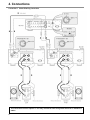
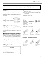
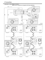
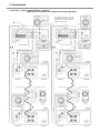
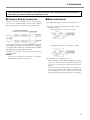
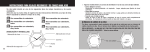
Model MA-9S1 User Guide
Monaural Power Amplifier
CAUTION
RISK OF ELECTRIC SHOCK
DO NOT OPEN
CAUTION: TO REDUCE THE RISK OF ELECTRIC SHOCK,
DO NOT REMOVE COVER (OR BACK)
NO USER-SERVICEABLE PARTS ARE INSIDE
REFER SERVICING TO QUALIFIED SERVICE PERSONNEL
The lightning flash with arrowhead symbol
within an equilateral triangle is intended to
alert the user to the presence of
uninsulated “dangerous voltage” within the
product’s enclosure that may be of
sufficient magnitude to constitute a risk of
electric shock to persons.
The exclamation point within an equilateral
triangle is intended to alert the user to the
presence of important operating and
maintenance (servicing) instructions in the
literature accompanying the product.
WARNING
TO REDUCE THE RISK OF FIRE OR ELECTRIC SHOCK,
DO NOT EXPOSE THIS PRODUCT TO RAIN OR MOISTURE.
CAUTION: TO PREVENT ELECTRIC SHOCK, MATCH THE
WIDE BLADE OF THE PLUG TO THE WIDE SLOT, AND
FULLY INSERT.
IMPORTANT SAFETY
INSTRUCTIONS
READ BEFORE OPERATING EQUIPMENT
This product was designed and manufactured to meet strict
quality and safety standards. There are, however, some
installation and operation precautions which you should be
particularly aware of.
1.
Read Instructions – All the safety and operating instructions
should be read before the product is operated.
2.
Retain Instructions – The safety and operating instructions
should be retained for future reference.
3.
Heed Warnings – All warnings on the product and in the
operating instructions should be adhered to.
4.
Follow Instructions – All operating and use instructions
should be followed.
5.
Cleaning – Unplug this product from the wall outlet before
cleaning. Do not use liquid cleaners or aerosol cleaners. Use
a damp cloth for cleaning.
6.
Attachments – Do not use attachments not recommended by
the product manufacturer as they may cause hazards.
7.
Water and Moisture – Do not use this product near water-for
example, near a bath tub, wash bowl, kitchen sink, or laundry
tub, in a wet basement, or near a swimming pool, and the
like.
8.
Accessories – Do not place this product on an unstable cart,
stand, tripod, bracket, or table. The product may fall, causing
serious injury to a child or adult, and serious damage to the
product. Use only with a cart, stand, tripod, bracket, or table
recommended by the manufacturer, or sold with the product.
Any mounting of the product should follow the
manufacturer’s instructions, and should use a mounting
accessory recommended by the manufacturer.
9.
10.
11.
12.
AC POLARIZED PLUG
13.
Power-Cord Protection – Power-supply cords should be
routed so that they are not likely to be walked on or pinched
by items placed upon or against them, paying particular
attention to cords at plugs, convenience receptacles, and the
point where they exit from the product.
14.
Protective Attachment Plug – The product is equipped with
an attachment plug having overload protection. This is a
safety feature. See the Instruction Manual for replacement or
resetting of the protective device. If replacement of the plug
is required, be sure the service technician has used a
replacement plug specified by the manufacturer that has the
same overload protection as the original plug.
15.
Outdoor Antenna Grounding – If an outside antenna or cable
system is connected to the product, be sure the antenna or
cable system is grounded so as to provide some protection
against voltage surges and built-up static charges. Article
810 of the National Electrical Code, ANSI/NFPA 70, provides
information with regard to proper grounding of the mast and
supporting structure, grounding of the lead-in wire to an
antenna discharge unit, size of grounding conductors,
location of antenna-discharge unit, connection to grounding
electrodes, and requirements for the grounding electrode.
See Figure 1.
16.
Lightning – For added protection for this product during a
lightning storm, or when it is left unattended and unused for
long periods of time, unplug it from the wall outlet and
disconnect the antenna or cable system. This will prevent
damage to the product due to lightning and power-line
surges.
17.
Power Lines – An outside antenna system should not be
located in the vicinity of overhead power lines or other
electric light or power circuits, or where it can fall into such
power lines or circuits. When installing an outside antenna
system, extreme care should be taken to keep from touching
such power lines or circuits as contact with them might be
fatal.
18.
Overloading – Do not overload wall outlets, extension cords,
or integral convenience receptacles as this can result in a
risk of fire or electric shock.
19.
Object and Liquid Entry – Never push objects of any kind into
this product through openings as they may touch dangerous
voltage points or short-out parts that could result in a fire or
electric shock. Never spill liquid of any kind on the product.
20.
Servicing – Do not attempt to service this product yourself as
opening or removing covers may expose you to dangerous
voltage or other hazards. Refer all servicing to qualified
service personnel.
21.
Damage Requiring Service – Unplug this product from the
wall outlet and refer servicing to qualified service personnel
under the following conditions:
A product and cart combination should be moved with care.
Quick stops, excessive force, and uneven surfaces may
cause the product and cart combination to overturn.
Ventilation – Slots and openings in the cabinet are provided
for ventilation and to ensure reliable operation of the product
and to protect it from overheating, and these openings must
not be blocked or covered. The openings should never be
blocked by placing the product on a bed, sofa, rug, or other
similar surface. This product should not be placed in a built-in
installation such as a bookcase or rack unless proper
ventilation is provided or the manufacturer’s instructions
have been adhered to.
Power Sources – This product should be operated only from
the type of power source indicated on the marking label. If
you are not sure of the type of power supply in your home,
consult your product dealer or local power company. For
products intended to operate from battery power, or other
sources, refer to the operating instructions.
Do not defeat the safety purpose of the polarized or
grounding-type plug. A polarized plug has two blades with
one wider than the other. A grounding type plug has two
blades and a third grounding prong. The wide blade of the
third prong is provided for your safety. If the provided plug
does not fit into your outlet, consult an electrician for
replacement of the obsolete outlet.
a.
When the power-supply cord or plug is damaged.
b.
If liquid has been spilled, or objects have fallen into the
product.
c.
If the product has been exposed to rain or water.
d.
If the product does not operate normally by following the
operating instructions. Adjust only those controls that are
covered by the operating instructions as an improper
adjustment of other controls may result in damage and will
often require extensive work by a qualified technician to
restore the product to its normal operation.
Table of Contents
1. Instruction for use ................................................................................................................. 2
Foreword ................................................................................................................................................................................ 2
Equipment mains setting .......................................................................................................................................................... 2
Copyright .................................................................................................................................................................................. 2
Precautions ............................................................................................................................................................................... 2
2. Accessories ........................................................................................................................... 2
3. Main features of this product ............................................................................................... 3
4. Connections ........................................................................................................................... 4
Connection 1 Stereo Bi-wiring Connection ..................................................................................................................... 4
B i - W i r i n g ........................................................................................................................................................................... 5
Wiring the speaker system ........................................................................................................................................ 5
Wiring speaker cable ................................................................................................................................................... 5
Connection 2 Stereo Bi-Amp Connection ........................................................................................................................ 6
Bi-Amp
(wiring) .............................................................................................................................................................. 7
Wiring the speaker system ........................................................................................................................................ 7
Connection 3 Stereo complete Bi-Amp Connection ....................................................................................................... 8
Complete Bi-Amp Connection ...................................................................................................................................... 9
Balanced
terminal ......................................................................................................................................................... 9
Installing the SACD multi-channel audio speakers ........................................................................................................... 10
Connection 4 5.1ch multi channel Connection ............................................................................................................... 11
Wiring speaker system ............................................................................................................................................... 11
5. Name and function .............................................................................................................. 12
6. Specification ........................................................................................................................ 13
7. Block diagram ...................................................................................................................... 13
8. Trouble shooting .................................................................................................................. 14
About
the
Protective
Circuit ................................................................................................................................ 14
9. Maintenance......................................................................................................................... 14
1
1. Instruction for use
■ Foreword
This section must be read before any connection is made to
the mains supply.
2. Accessories
After opening the cover of the packing box, check that the
following accessories are included.
●
AC Power Cable
■ Equipment main AC power setting
Your Marantz product has been prepared to comply with the
household power and safety requirements that exist in your
area.
MA 9S1/N1G can be powered by 230 V AC only.
MA 9S1/U1G can be powered by 120 V AC only.
■ Copyright
Recording and playback of any material may require consent. For further information refer to the following:
—
—
—
—
Copyright Act 1956
Dramatic and Musical Performers Act 1958
Performers Protection Acts 1963 and 1972
any subsequent statutory enactments and orders
■ Precautions
The following precautions should be taken when operating
the equipment.
● General Precautions
When installing the equipment ensure that:
—
—
—
—
—
—
—
the ventilation holes are not covered;
air is allowed to circulate freely around the equipment
it is on a vibration free-surface;
it will not be exposed to interference from an external
source;
it will not be exposed to excessive heat, cold, mois
ture or dust;
it will not be exposed to direct sunlight;
it will not be exposed to electrostatic discharges
Never place heavy objects on the equipment.
If a foreign body or water does enter the equipment, contact
your nearest dealer or service center.
Do not pull out the plug by pulling on the mains lead, pull from the
plug itself. It is advisable when leaving the house, or during a
thunderstorm, to disconnect the equipment from the mains supply.
2
(MA 9S1/N1G)
●
Instruction Manual (this Copy)
(MA 9S1/U1G)
3. Main features of this product
● The concept : Instantaneous current
delivery capability
Even if amplifiers have the same power specifications, their
performance may not be the same due to a difference in
current delivery capability.
The delivery capability of power amplifiers depends on how
instantaneous the current supply is.
That’s why the power supply for the MA-9S1 was completely
revamped to give it a truly instantaneous current supply capability that has been increased three times as much compared to any Marantz product designed before.
● Fully balanced monaural power amp
To minimize the influence of strong “return current” occurring
from the loudspeaker system, the circuit for the power amp
consists of two amplifiers giving a voltage gain amp of 23dB,
in a push-pull balanced construction, for the final buffer amp
of 6dB.
● HDAM SA
The feedback impedance of the Current Feedback circuit was
reduced to its minimum to make it faster.
We developed a new High Definition Amplifier Module
(HDAM), a separated module operating as a buffer for
the amplifier.
● Choke input system
The power supply of the voltage gain amplifier’s adopted
choke input system has few ripples and is durable with load
changes.
This can prevent noise from the amplifier as well as reduce
noise from the primary winding, resulting in a clean power
supply.
● Ultra low impedance amplifier
The buffer amplifier’s power supply block, which supports the
high current delivery capability, uses a capacitance input
system to realize very low impedance.
The Super Ring Power transformer, the low impedance electrolytic capacitors, the very large gauge internal wiring, and
the thick pattern PCB all contribute in supplying the required
power.
3
4. Connections
Connection 1 Stereo Bi-wiring Connection
This connection can have options i.e. You may connect the units using either balanced or unbalanced
cables.
4
4. Connections
Connection 1 - 4 are recommended by Marantz for the SC-7S1 with Marantz MA-9S1s.
All Connections are based on speaker systems that are capable of Bi-Wiring.
Please read the instruction manual for the SC-7S1 for use. Name and Function ➔ P12
■ Bi-Wiring
●
The method is to improve sound quality, by connecting speaker
cable respectively to each terminal for Bass and Mid/High speakers. This method will reduce interference caused by the bass
speaker and the Mid/High speaker unit being powered by the
same amplifier.
●
●
Be careful not to short circuit or touch the speaker
cables to each other.
Peel off the coating or insulation of the speaker cable
as shown below.
Wiring with speaker cable.
Approx. 1 cm
Cut the coating
or insulation
■ Wiring the speaker system
● Speaker system doesn’t comply with the Bi-Wiring
Peel off the edge
of the cable.
Twist conductors.
of the speaker
cable.
●
Wiring with “Y” style terminal
Please connect either of the speaker terminals 1 or 2. And
please use a speaker system whose impedance is for 4 16Ω. If impedance is lower than 4Ω, the protection circuit will
be engaged during play. This will result in no output of the
Amplifier.
● Speaker system complies with the Bi-Wiring
Please connect both of the speaker terminals 1 and 2.
And please use a speaker system whose impedance is
for 4 - 16Ω. If impedance is lower than 4Ω, protection
circuit will be engaged during play. This will result in no
output of the Amplifier.
Turn counter-clockwise to loosen.
Insert conductor
of cable.
Turn clockwise to
tighten.
Connection 2 Stereo Bi-Amp connection.
● Polarity of Speaker output terminal
Speaker terminals have positive (+ : Red) and negative (– :
White) polarity and speaker wires also have (+ & –) polarity.
In wiring, be sure to connect the terminals with the same polarity (+ and +, – and –).
■ Wiring the speaker
Turn counter-clockwise to loosen.
Insert conductor.
Turn clockwise to
tighten.
CAUTION:
When connecting two pairs of speaker systems simultaneously, the impedance of each speaker system should
be no less than 8 ohm .
Connecting a speaker system with a lower impedance than
8 ohm may activate the protection circuitry and make normal stereo reproduction impossible.
5
4. Connections
Connection 2 Stereo Bi-Amp connection.
(Make sure your speakers are designed for Bi Amp capabilities)
6
4. Connections
Enhance connection 1 to Bi-Amp connection, and drive the
bass speaker and Mid / High Frequency speakers with separate power Amplifiers.
■ Bi-Amp (connection)
The benefits of Bi-Wiring; drive the bass speaker and Mid / High
speakers with separate power Amplifiers. Bi-Amping will lessen
the burden of Power Amp impedance, so that back electromotive force between the Low and Mid/High signal can be lessened. We can expect drastic improvement of sound quality.
Caution :
In the event of this connection (Control Amp SC-7S1 is
<Stereo>mode), SC-7S1 and MA-9S1 can be wired by Unbalanced only.
■ Wiring the speaker system
●
●
●
Please remove short bar of the speaker terminal.
If the short bar, has not been removed, it will damage the
power amplifier.
Please use speaker systems whose impedance are for 4 16Ω.
If impedance is lower than 4Ω, the protection circuit will be
engaged during play.
Make sure your speakers are designed for Bi Amp capabilities. If they don’t the protection circuit will be engaged and
there will be no output. Or it will damage the power amplifier.
7
4. Connections
Connection 3 Stereo complete Bi-Amp connection.
(Make sure your speakers are designed for Bi Amp capabilities)
As shown by connection 3 or 4, the
control Amp SC-7S1 can be controlled
through sets by wiring with the
equipped remote control.
8
4. Connections
This connection can have options i.e. You may connect the units using either balanced or unbalanced
cables. But, you have to use the same cables per SC 7S1.
■ Complete Bi-Amp Connection
Enhance connection 2, by having one more control Amp. SC7S1. This is a Complete Bi-Amp connection which separates
Mid / High signal and Low signal from the Pre-Amp section.
In this event, the SC-7S1 is using Monaural Amps. And separate Left/Right channels from the output terminal of CD players.
As a result, influences between L channel and R channel Mid /
High signal and Low signal will be eliminated.
A maximum of 6 SC-7S1s, can be connected to each other,
via remote cables.
■ Balanced terminal
햲 The balanced output connector uses a XLR connector.
햳 The XLR connector is internally wired in either of the following two systems.
1. USA system (Pin 2 = COLD, Pin 3 = HOT)
2. European system (Pin 2 = HOT, Pin 3 = COLD)
Caution
In the event of setting the mode switch as <Bi-Amp>,
B channel input terminals can’t be used.
햴 The MA-9S1 uses the USA system of 1.
When a preamp or main amplifier adopting the European
system is connected using a cable with XLR balanced
connectors, the reproduced signal may be inverted of
phase.
In this case, correct the wiring of the one of the XLR connectors on the extremities of the cable to the USA system
by exchanging the connections of pins 2 and 3. This will
make it possible to play the signal with the correct phase.
9
4. Connections
■ Installing the SACD multi-channel
audio speakers
In order to enjoy SACD multi-channel sound with the best possible acoustics, it is recommended that the speaker systems be
laid out in compliance with the ITU-R BS.775-1 recommendation which is a standard formulated by the International Telecommunication Union (ITU).
SACD multi-channel discs are recorded and mixed in such a
way that they will achieve the optimum effects when the
speaker systems are laid out as per the ITU-R BS.775-1 recommendation.
●
●
●
On SACD multi-channel discs, the music signals are basically recorded using 5 channels (or 3, 4 or 6 channels in
some cases). In some instances, however, LFE (for the sub
woofer) is recorded as a sixth channel.
Each disc indicates how many channels have been recorded
on it.
The basic settings are 3 speakers for front and 2 for back
since multi-channel discs have basically 5 channels
The 2-front, 1-center, and 2-surround speakers should
be set on the circle from the listening point as shown
below.
When you use different sizes of speakers, please adjust
the volume balances.
The location of the sub-woofer in the picture is just an
example. The Sub-woofer can be located any place in
your room. (See the users manual of your sub-woofer.)
Sub-woofer
Center
speaker
Front speaker
(Left)
Front speaker
(Right)
60°
approx. 110°
approx. 110°
Reference listening
position
Rear speaker
(Left Surround)
10
Rear speaker
(Right Surround)
4. Connections
This connection can have options i.e. You may connect the units using either balanced or unbalanced cables. But, you have to use the same cables per SC 7S1.
Connection 4 5.1ch multi-channel connection
Below is the standard connection for a Multi-channel sound source. This will enable you to experience the high quality sound
acoustic for the professional Home theatre and pure multi channel SACD. The complete 5.1 system is controlled using 3 SC-7S1
Stereo Control Amplifiers.
The system can be enhanced to
●
●
<3 SC-7S1s + 10 MA-9S1s + Active sub-woofer>
<6 SC-7S1s + 10 MA-9S1s + Active sub-woofer>
■ Wiring speaker system
Please refer to <Wiring speaker system> p.5 of connection 1.
Caution
●
●
If you use an Active (powered) sub-woofer for LFE, please refer to the Users manual of the Active sub-woofer for set up
instructions. LFE (Low Frequency Effect) is the channel for Low Frequency only.
If you use a Passive sub-woofer for LFE, a Monaural power Amp such as the MA-9S1 can be used to drive it.
11
5. Name and function
Front panel
Rear panel
햲 Power switch
햵 Level meter
햷 ATT (Attenuator)
햺 Speaker output terminal
Press the power switch to turn the power on/off. When the
power is on, the power indicator 3 will be illuminated.
This meter is used to check the output power.
The knob is to attenuate the input level.
Initial set up is 0dB.
Connect your speaker system to these terminals.
Speaker cable wiring → p.5
햸 Balanced input terminal
햻 AC IN socket
Connect to the Balanced output terminal of the Pre-Amp.
Connect to a household power outlet.
Meter indication vs Output power
햳 Input selector
This knob is to select the input source from the Pre-Amp.
햴 Power indicator
The power indicator is illuminated while the power switch is
on.
Indicated level (dB)
0
–10
–20
–30
–40
8ΩLoad(W)
300
30
3
0.3
0.03
4ΩLoad(W)
600
60
6
0.6
0.06
Connect to the Unbalanced output terminal of the Pre-Amp.
햶 Meter off switch
This switch is used to turn on/off the level meter and the internal
light of the level meter.
12
햹 Unbalanced input terminal 1, 2
6. Specification
■ Specification
■ Dimensions
Unit : mm
Power Output (20Hz - 20kHz) ................................. 300W (8Ω Load)
600W (4Ω Load)
T.H.D. (20Hz - 20kHz, 8Ω Load) ............................................. 0.01%
Frequency response (1W, 8Ω Load) .......................... 3 Hz - 120 kHz
(+0, –3dB)
Damping factor ............................................................................ 200
(20Hz - 20kHz, 8Ω Load)
Input sensitivity/ Input impedance ............... 1.7V / 20kΩ (Balanced)
1.7V / 20kΩ (Unbalanced)
S/N (IHF-A) .......................................................... 120 dB (Balanced)
120 dB (Unbalanced)
Attenuation ................................................ 0, –3, –6, –9, –12, – ∞ dB
Power requirement (MA 9 S1/N1G) ........................ AC 230V 50Hz
(MA 9S1/U1G) ......................... AC 120V 60Hz
Power Consumption (MA 9S1/N1G) .......................... 500 W (3.2 A)
(MA 9S1/U1G) .......................... 500 W (5.8 A)
1200 W (Output: 4Ω, 600W)
Dimensions ................................................................ Width 459 mm
Height 198 mm
Depth 451 mm
Weight ................................................................................... 35.8 kg
* All specifications, dimensions and weights are subject to change without notice.
7. Block diagram
UNBALANCED
2
1
3
ATT
INPUT
I/V
I/V
1
BALANCED
2
SPEAKER
OUTPUT
I/V
I/V
ATT
INPUT
SELECTOR
PROTECT
FINAL STAGE
INPUT / DRIVE STAGE
SOFT
START
REGULATOR
METER / PROTECT
13
8. Trouble shooting
Should faults occur, in many cases it is not necessary to consult your dealer or a Marantz technical service department.
On the basis of the following checks you will be able to rectify
a number of faults yourself without difficulty.
If the fault cannot be remedied after the following checks,
please consult your dealer or nearest Marantz service agent.
The unit does not turn ON
1. Is the power cable securely plugged into an AC outlet?
Sound is not coming from the speakers
1. Has the wrong input source been selected with the INPUT SELECTOR on the front panel?
2. Is the ATTENUATOR switch set to -∞ on the rear panel?
3. Are speaker cables properly connected to the speaker
system?
4. Is the connection cable properly connected to the control (pre) amplifier?
5. Is the control (pre) amplifier or input source wrongly set?
6. Are you using the player in the wrong way?
7. The protective circuit of this unit may have worked. Shut
power OFF, wait 1 minute or more, then reactivate the
power.
9. Maintenance
The section describes the care and maintenance tasks that
must be performed to optimize the operation of your Marantz
equipment.
● Cleaning of equipment external surfaces
The exterior finish of your unit will last indefinitely with proper
care and cleaning, Never use scouring pads, steel wool,
scourging powders or harsh chemical agents (e.g., lye solution), alcohol, thinner, benzene, insecticide or other volatile
substances as these will mar the finish of the equipment. Likewise, never use cloths containing chemical substances. If the
equipment gets dirty, wipe the external surfaces with a soft,
lint-free cloth.
If the equipment becomes heavily soiled:
• dilute some washing liquid in water, in a ratio of one part
detergent to six parts water.
• dip a soft, lint free cloth in the solution and wring until it is
damp.
• wipe the equipment with the damp cloth.
• dry the equipment by wiping it with a dry cloth.
■ About the Protective Circuit
This unit incorporates a protective circuit that protects the
amplifier circuit and speaker system against damage. If the
protective circuit works, the meter lights shut off and the sound is
muted. (Pressing the METER OFF switch also shuts off the meter
lights.) This protective circuit works in the following cases.
● At power ON
When power is activated, the protective circuit works and
mutes the sound for about 8 seconds until the amplifier circuit stabilizes. Once the amplifier circuit stabilizes, the protective circuit releases and muting is canceled. At the same
time, the meter lights turn ON.
● If overcurrent flows to the amplifier circuit
(Overcurrent protection)
If overcurrent flows to the amplifier circuit because of excessive signal input or if the unit is used with speakers of less
than 4 Ω impedance connected to it, overcurrent is detected
and the protective circuit will engage. The protective circuit
also will engage if the speaker cables are accidentally shorted.
If the protective circuit engages, the meter lights shut off, therefore you will know whether or not that is the problem by checking the meter lights.
If it has engaged, shut the power OFF, wait 1 minute or more,
then reactivate the power.
● If the amplifier overheats
In the following cases, the amplifier will overheat and the protective circuit will engage.
• If the unit is used with the ventilation blocked or obstructed
• If speakers of less than 4 Ω impedance are used
• If the unit is used for an extended period of time under
excessive signal input.
14
● Repairs
Only the most competent and qualified service technicians should
be allowed to service your unit. The factory-trained warranty
station personnel have the knowledge and special facilities
needed for repair and calibrate this precision equipment. After
the warranty period has expired, repairs will be performed for a
charge.
In the event of difficulty, refer to your dealer or write directly to
the nearest location to you that is listed on the Marantz Authorized Service Station list. If writing, please include the model
and serial number of the equipment together with a full description of what you think is abnormal about the equipment's
behavior.
WARRANTY
For warranty information, contact your local Marantz distributor.
RETAIN YOUR PURCHASE RECEIPT
Your purchase receipt is your permanent record of a valuable purchase. It should be kept in a safe place to be referred to as necessary
for insurance purposes or when corresponding with Marantz.
IMPORTANT
When seeking warranty service, it is the responsibility of the consumer to establish proof and date of purchase. Your purchase receipt or
invoice is adequate for such proof.
FOR U.K. ONLY
This undertaking is in addition to a consumer's statutory rights and does not affect those rights in any way.
CE MARKING
The MA9S1/N1G is in conformity with the EMC directive and low-voltage directive.
WARNINGS
–
–
–
–
–
–
–
–
–
–
Do not touch the top of the enclosure during operation.
Do not expose the equipment to rain or moisture.
Do not remove the cover from the equipment.
Do not insert anything into the equipment through the ventilation holes.
Do not handle the mains lead with wet hands.
Do not cover the ventilation with any items such as tablecloths, newspapers, curtains, etc.
No naked flame sources, such as lighted candles, should be placed on the equipment.
When disposing of used batteries, please comply with governmental regulations or environmental public instruction’s rules that apply in your country or area.
Do not place anything about 1 meter above the top panel.
Make a space of about 0.2 meter around the unit.
www.marantz.com
You can find your nearest authorized distributor or dealer on our website.
U.S.A.
Marantz America, Inc.
1100 Maplewood Drive, Itasca, IL 60143, U.S.A.
is a registered trademark.