1
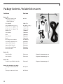
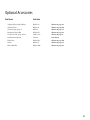
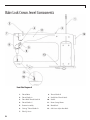
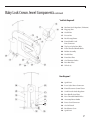
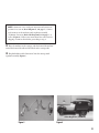
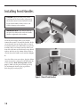
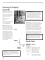
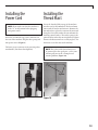
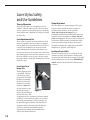
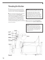
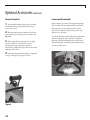
To register your machine warranty and receive Baby Lock product updates and offers, go to
www.babylock.com/profile. If you have questions with registration, visit your Authorized Baby Lock Retailer.
IMPORTANT SAFETY INSTRUCTIONS
This device complies with Part 15 of the FCC Rules. Operation is subject to the following two conditions: (1)
This device may not cause harmful interference, and (2) this device must accept any interference received, including interference that may cause undesired operation.
When using an electrical appliance, basic safety precautions should always be followed, including the following:
Read all instructions before using this quilting machine.
Please keep all packaging and order information for warranty purposes.
DANGER - To reduce the risk of electric shock:
• A quilting machine should never be left unattended when plugged in. Always unplug this quilting machine
from the electric outlet immediately after using and before cleaning.
WARNING - To reduce the risk of burns, fire, electric shock, or injury to
persons:
• Do not allow to be used as a toy. Close attention is necessary when this quilting machine is used by or near
children.
• Use this quilting machine only for its intended use as described in this manual. Use only attachments recommended by the manufacturer as contained in this manual.
• Never operate this quilting machine if it has a damaged cord or plug, if it is not working properly, if it has been
dropped or damaged, or dropped into water. Return the quilting machine to the nearest authorized dealer or
service center for examination, repair, electrical or mechanical adjustment.
• Keep fingers away from all moving parts. Special care is required around the quilting machine needle.
• Always use the proper needle plate. The wrong plate can cause the needle to break.
• Do not use bent or dull needles.
• Switch the quilting machine off (“0”) when making any adjustments in the needle area, such as threading needle, changing needle, threading or servicing the bobbin, etc.
• Always unplug quilting machine from the electrical outlet when removing covers, lubricating, or when making
any other user servicing adjustments mentioned in the instruction manual.
• Never drop or insert any object into any opening.
• Do not use outdoors.
• Do not operate where aerosol (spray) products are being used or where oxygen is being administered.
• To disconnect, turn all controls to the off (“0”) position, then remove plug from outlet.
• Do not unplug by pulling on cord. To unplug, grasp the plug, not the cord.
• Never operate the quilting machine if the cord is damaged or not working correctly. If a mechanical or electrical problem is encountered, return the quilting machine to the nearest
SAVE THESE INSTRUCTIONS
GROUNDING
GROUNDED OUTLET BOXES
TAB FOR
GROUNDING
SCREW
METAL
SCREW
GROUNDING PIN
ADAPTER
(A)
(B)
(C)
Figure 1
This product is for use on a nominal 120 V or nominal 220 V circuit, and has a grounding plug that looks like
the plug illustrated in sketch A in Figure 1. A temporary adapter, which looks like the adapter illustrated in
sketches B and C, may be used to connect this plug to a 2-pole receptacle as shown in sketch C if a properly
grounded outlet is not available. The temporary adapter should be used only until a properly grounded outlet can be installed by a qualified electrician. The green colored rigid ear, lug, and the like, extending from the
adapter must be connected to a permanent ground such as a properly grounded outlet box cover. Whenever the
adapter is used, it must be held in place by the metal screw.
Note: In Canada, the use of a temporary adapter is not permitted by the Canadian Electric Code.
Baby Lock Crown Jewel Contents
Baby Lock Crown Jewel Quick Facts . . . . . . . . . . . . . . . . . . . . . . . . . . . . . . . . . . . . . . . 2
Baby Lock Crown Jewel Disclaimer. . . . . . . . . . . . . . . . . . . . . . . . . . . . . . . . . . . . . . . . 2
Home Machine Quilting Frame Recommendation. . . . . . . . . . . . . . . . . . . . . . . . . . . 3
Baby Lock Crown Jewel Safety Section. . . . . . . . . . . . . . . . . . . . . . . . . . . . . . . . . . . . . 3
Package Contents/Included Accessories. . . . . . . . . . . . . . . . . . . . . . . . . . . . . . . . . . . . 4
Optional Accessory Listings. . . . . . . . . . . . . . . . . . . . . . . . . . . . . . . . . . . . . . . . . . . . . . 5
Baby Lock Crown Jewel Components
Front-Side Diagram A. . . . . . . . . . . . . . . . . . . . . . . . . . . . . . . . . . . . . . . . . . . . . . . . . 6
Back-Side Diagram B. . . . . . . . . . . . . . . . . . . . . . . . . . . . . . . . . . . . . . . . . . . . . . . . . 7
Rear Diagram C. . . . . . . . . . . . . . . . . . . . . . . . . . . . . . . . . . . . . . . . . . . . . . . . . . . . . . 7
Installing Machine on Carriage. . . . . . . . . . . . . . . . . . . . . . . . . . . . . . . . . . . . . . . . . 8-9
Installing Front Handles. . . . . . . . . . . . . . . . . . . . . . . . . . . . . . . . . . . . . . . . . . . . . . . . 10
Installing Rear Handles . . . . . . . . . . . . . . . . . . . . . . . . . . . . . . . . . . . . . . . . . . . . . . . . 11
Cluster LED Pin Light Installation and/or Replacement. . . . . . . . . . . . . . . . . . . . . . 11
Inserting (or Changing) the Needle/Needle Guide. . . . . . . . . . . . . . . . . . . . . . . . . . 12
Installing the Power Cord. . . . . . . . . . . . . . . . . . . . . . . . . . . . . . . . . . . . . . . . . . . . . . . 13
Installing the Thread Mast. . . . . . . . . . . . . . . . . . . . . . . . . . . . . . . . . . . . . . . . . . . . . . 13
Laser Stylus Safety and Use Guidelines . . . . . . . . . . . . . . . . . . . . . . . . . . . . . . . . . . . 14
Installing the Laser Stylus. . . . . . . . . . . . . . . . . . . . . . . . . . . . . . . . . . . . . . . . . . . . . . 15
Threading the Machine . . . . . . . . . . . . . . . . . . . . . . . . . . . . . . . . . . . . . . . . . . . . . 16-17
Bobbin and Thread Tension Adjustments. . . . . . . . . . . . . . . . . . . . . . . . . . . . . . . 18-20
Maintenance. . . . . . . . . . . . . . . . . . . . . . . . . . . . . . . . . . . . . . . . . . . . . . . . . . . . . . . . . 20
Using the Touch Screen Displays on the Handlebars. . . . . . . . . . . . . . . . . . . . . . 21-28
Baby Lock Crown Jewel Regulator Setup. . . . . . . . . . . . . . . . . . . . . . . . . . . . . . . . . . 29
To Begin Quilting. . . . . . . . . . . . . . . . . . . . . . . . . . . . . . . . . . . . . . . . . . . . . . . . . . . . . . 30
Troubleshooting . . . . . . . . . . . . . . . . . . . . . . . . . . . . . . . . . . . . . . . . . . . . . . . . . . . 31-36
Variable Speed Bobbin Winder. . . . . . . . . . . . . . . . . . . . . . . . . . . . . . . . . . . . . . . . . . 37
Bobbin Winder Instructions. . . . . . . . . . . . . . . . . . . . . . . . . . . . . . . . . . . . . . . . . . 38-39
Optional Accessories
Channel Lock. . . . . . . . . . . . . . . . . . . . . . . . . . . . . . . . . . . . . . . . . . . . . . . . . . . . . . . 40
Ruler Base. . . . . . . . . . . . . . . . . . . . . . . . . . . . . . . . . . . . . . . . . . . . . . . . . . . . . . . . . 40
Stylus and Adaptor Plate with Holder. . . . . . . . . . . . . . . . . . . . . . . . . . . . . . . . . . 41
Horizontal Spool Pin. . . . . . . . . . . . . . . . . . . . . . . . . . . . . . . . . . . . . . . . . . . . . . . . . 42
Crown Jewel Micro Handles. . . . . . . . . . . . . . . . . . . . . . . . . . . . . . . . . . . . . . . . . . . 42
1
Baby Lock Crown Jewel
Quick Facts
Baby Lock Crown Jewel
Disclaimer
Sewing Speed
Approximately 1,800 spm
Minimum Sewing Speed
90 spm
Needle Bar Stroke
35.3 mm
Sewing Foot Stroke/Lift
5 mm
Needle System
135x7 Standard
Needle Sizes
14/90 – 20/120
Baby Lock and its authorized retailers
are not legally responsible or liable for damage to the Baby Lock Crown Jewel when
used improperly or not in accordance with
the guidelines stated in this manual or when
used on Home Machine Quilting Frames
not recommended by Baby Lock.
Lubrication, main
components
Kluber Lube, permanent
Lubrication, hook
Velocite 10, Texaco 22
Dimensions of
Sewing Machine Throat
8.25˝ x 18.00˝
Rate Voltage/
Power Consumption
120 volts,
60 Hz 300 watts
Power Consumption
of LED Lights
10 watts
Hook System
Custom Manufactured,
Rotary, Large Bobbin
Bobbin Type
Class M
Motor Type
Brushless DC, Internal Encoding
Automatic Needle
Positioning
Up and down, full-stitch and
half-stitch
Cluster Lights
LED lights
2
For additional product information, visit
our website at: www.babylock.com.
Home Machine
Quilting Frame
Recommendation
•
Grace Pinnacle Frame
•
Grace Majestic Frame
Baby Lock Crown Jewel
Safety Section
NOTE: Do not operate your Baby Lock Crown Jewel quilting machine until you have completely read the information
contained in this manual. Please keep all packaging and order
information for warranty purposes.
1. Always unplug the Baby Lock Crown Jewel from the
electric outlet when performing any maintenance, changing the needle, removing thread locks, or when left unattended.
2. Keep fingers away from all moving parts. Use caution
around the needle or sharp external components.
3. Change the needle often. Do not use bent or dull
needles.
4. Switch the power off when making any adjustments in
the needle or bobbin area, such as threading the needle,
installing the bobbin case, oiling or when cleaning.
5. Never drop or insert foreign objects into any opening.
6. The Baby Lock Crown Jewel should only be used indoors
away from moisture.
7. The Baby Lock Crown Jewel should not be stored or used
in extreme temperatures.
8. Use the Baby Lock Crown Jewel only for its intended
use as described in this manual.
9. Use only attachments recommended by the
manufacturer in this manual.
10. To disconnect from the wall outlet, push the switch to
the off position, then remove the plug from outlet pulling from the plug, not the cord. Never operate the Baby
Lock Crown Jewel if the cord is damaged in any way. If a
mechanical or electrical problem is encountered, please
consult local authorized Baby Lock retailer.
3
Package Contents /Included Accessories
Part Name
Part Code
Box 1 of 4
Baby Lock Crown Jewel Quilting Machine /
Stitch Regulator
BLCJ18
User Manual
IBBLCJ18
Class M Bobbins (5 pieces) BLJ-BOB (3 pkg.)
Needle size 16 (1 pkg. of 10) 134FG-100
Needle size 18 (1 pkg. of 10) 134FG-110
Bobbin Case
JW000586
Thread Mast
JW010214
Oiler
JW010272
Power Cord
JW020277
Brush
JW010270
Disc-shaped Screwdriver XC1074051
Screwdriver (bobbin case)
JW010269
3.0mm Allen Wrench
JW010287
5.0mm Allen Wrench JW010289
Laser Stylus and Clamp
JW020259
Laser Stylus Post
JW010290
Box 2 of 4
Front Handles JW029418
Figure 5 shown on page 10
Rear Handles JW029388
Figure 6 shown on page 11
JW029307
Figure 1 shown on page 37
Box 3 of 4
Variable-Speed Bobbin Winder Box 4 of 4 (Contains one only)
Carriage for Pinnacle Frame or
Carriage for Majestic Frame 4
BLCJ18D1
BLCJ18D2
Optional Accessories
Part Name
Part Code
Adaptor Plate/Stylus Holder BLJ18-SA Shown on page 41
Channel Lock BLJ18-CL Shown on page 40
Cluster Lights (pkg. 2) BLJ18-L Shown on page 11
Horizontal Spool Pin BLJ18-HS Shown on page 42
Needle size 20 (1 pkg. of 10) 134FG-125 Shown on page 4
Quilt Pattern Boards
Various Not shown
Ruler Base BLJ18-RB Shown on page 40
Stylus BLJ18-ST Shown on page 41
Micro Handles BLJ18-MH Shown on page 42
5
Baby Lock Crown Jewel Components
Front-Side Diagram A
6
1. Thread Mast
8. Thread Guide E
2. Thread Guide A
9. Needle Bar Thread Guide
3. Three Hole Thread Guide B
10. Needle
4. Thread Guide C
11. Front Casing/Frame
5. Tension Assembly
12. Handwheel
6. “Stirrup” Thread Guide D
13. Side Laser Stylus Post Hole
7. Take Up Lever
Baby Lock Crown Jewel Components continued
Back-Side Diagram B
14. Machine Stitch Regulator (Y-Motion)
15. Hopping Foot
16. Needle Bar
17. Presser Bar
18. Back Casing/Frame
19. Front Handle Serial
Port Connector
20. Top Laser Stylus Post Hole
21. Front Threaded Handle Holes
22. Bobbin Assembly
23. Needle Plate
24. Front Base Plate
25. Oval Position Guides
26. Rear Base Plate
27. Wheels (4)
Rear Diagram C
28. Spool Pin 1
38
29. Laser Stylus Power Connector
30. Front Electronic Control Cover
37
31. Serial Port for Stitch Regulator
32. Rear Handle Serial Port
36
33. Rear Threaded Handle Holes
35
34. Accessory Power Outlet
34
35. Power Cord Connector
36. On/Off Switch
37. Back Power Cover
38. Spool Pin 2
7
Installing Machine
on Carriage
1.
Place the carriage on the table rails ensuring that the carriage
stitch regulator assembly is toward the back of the table (Figure 1).
Front of
table
2. The stitch regulator, machine and carriage are connected by a
ribbon cable that has 3 connectors (Figure 3, page 9). The machine
should arrive from the factory with the ribbon cable already attached
by Connectors A and B. The remaining end, Connector C, will be
connected in Step 4.
IMPORTANT NOTE: Very carefully remove the plastic wire
tie securing the Carriage Stitch Regulator Assembly (XMotion) after the carriage is placed onto the tracks of the
quilting frame (Figure 2).
Carriage
Stitch
Regulator
Assembly
(X-Motion)
Back of
table
Figure 1
Plastic Wire Tie
Figure 2
8
NOTE: Connector A is a serial port connector and connects at
position 31 as seen in (Rear Diagram C, #31 page 7). Connector B connects to the machine stitch regulator assembly
(Y-Motion) shown in (Back-Side Diagram B, #14 page 7), as
well as (Figure 4). If these two connections have come loose in
shipping, reconnect them before proceeding to step 3.
3. Place the machine on the carriage, with the front of the machine
toward the front of the table and all wheels on the carriage rails.
4. Plug final ribbon cable Connector C into the carriage stitch
regulator assembly (Figure 1).
B
C
Figure 3
A
Stitch Regulator (Y-Motion)
Figure 4
9
Installing Front Handles
CAUTION: Unplug the Baby Lock Crown
Jewel from the electrical outlet. All power to
the machine must be turned off when installing the front handles. Failure to do so can
result in damage to the machine.
IMPORTANT NOTE: Care must be taken to
not pinch the ribbon cable under the handle
when it is tightened to the machine.
Locate the three longest Allen screws and the
5.0mm Allen wrench. To install the handles, tilt the
screen forward. Line up the three holes on top of
the handles with the pre-drilled holes on top of the
machine. Slide a star washer onto the Allen screw,
then slide a bolt into each hole until it stops. Hand
tighten, and then use the 5.0mm Allen wrench to
securely fasten the handles to the machine (Figure
4).
Figure 4
Once the Allen screws are in place, plug the ribbon
connector into the serial port on the left-hand side
of the machine (Back-Side Diagram B, #19 on
page 7). Make sure the pins are lined up so they
are not damaged when the plug is pushed in.
Push the plug securely in place.
Figure 5 (View of Front Handles)
10
Installing Rear Handles
CAUTION: Check that the Baby Lock Crown Jewel is unplugged from the electrical outlet. All power to the machine
must be turned off when installing the back handles. Failure to
do so can result in damage to the machine.
IMPORTANT NOTE: Care must be taken to not pinch the ribbon cable under the handle when it is tightened to the machine.
The rear handles already come mounted by three Allen screws into an
“L” bracket. Line up the two holes in the “L” bracket with those on the
rear of the machine. Slide the two short Allen screws into holes until
they stop. Hand tighten, and then use the 5.0mm Allen wrench to
securely fasten the handle to the back of the machine.
Once the two Allen screws are in place, plug the 9-pin ribbon connector into the serial port underneath the rear handle (Rear Diagram C, #32 page 7). Ensure the pins are lined up so they are not
damaged when the plug is pushed in. Push the plug securely in place.
NOTE: After the handles have been completely installed and
plugged in, test them by turning the Baby Lock Crown Jewel on/
off switch to “on”. The handles will run a self-test by briefly displaying their version during boot up, and then the LED lights on the
front handles will illuminate. After the boot up is completed,
both LCD displays (front handle and rear handle) will display
the same menu. If nothing is displayed or if the lights don’t illuminate, check that the handle cable on the side of the machine
is plugged in securely, that your machine is turned on, and that
the power cord is plugged into the machine as well as a power
source.
Cluster LED Pin Light
Installation and/or
Replacement
The Cluster LED
(Figure 7) pin lights
are located on the
underside of the
front handles. While
LED lights have
a very long life
expectancy, ocFigure 7
casionally you may
need to replace one
or you may choose to add more Cluster LED pin
lights for additional lighting (available from your
Baby Lock retailer). You may add up to 10 additional LED Clusters on the front handles if desired.
Removal:
1. Shut off the power to the machine.
2. Grasp the Cluster LED pin light by the base of
the cluster with your fingertips.
NOTE: Do not grasp the LEDs themselves, as
they may break.
3. Pull straight downward without twisting (slight
rocking back and forth may be required).
4.
If you are unable to remove the lights with your
fingers, you may use an extraction tool or a pair of
needle-nose pliers to carefully grasp the base of the
light cluster and pull downward.
Installation:
1. Shut off the power to the machine.
2. Insert the new Cluster LED pin light, matching
the three pins with the three holes in the receptacle
(orientation is not critical).
3.
Figure 6 (View of Back Handles)
Press firmly until the LED pin light is fully
inserted (the base will be against the metal closing
plate of the handle).
11
Inserting (or Changing)
the Needle
1. Move the needle bar to the
highest position by turning the
handwheel counterclockwise
or pressing the needle up/down
control on the handles.
2. Turn all power to
Needle
Bar
Clamp
Screw
machine off.
3.
Loosen the needle bar clamp
screw with the appropriate
screwdriver (Figure 8).
Figure 8
NOTE: Changing the needle is recommended
for each new quilt loaded on the machine
or any time the needle becomes bent, dull
or burred.
Groove/
Front Side
Diagram D
(Side View)
CAUTION: Never leave machine unattended
when plugged in. Always unplug this machine
from the electrical outlet immediately after using
and before maintenance.
12
5.
Carefully tighten the needle bar clamp screw.
Over tightening the needle clamp screw will result
in damaging the screw by stripping the threads.
Stripped threads are not covered under warranty. A side effect of damaged threads from over
tightening the needle clamp screw is that it may
become difficult to insert the needle properly into
the needle bar. To avoid over tightening the screw,
while using the screwdriver, is once the screw no
longer turns freely is to then gently turn the screwdriver until the screw is tightened snuggly.
4.
Referring to Diagram D,
with the scarf (small recess area
on the back side of the needle,
just above the needle eye) facing
toward the rear of the machine
(handwheel location) and the
long groove down the front of
the needle facing the front of the
machine (bobbin case location),
push the needle all the way up
into the needle bar until it stops.
Check the sight opening to
verify that the top of the needle
can go no farther.
IMPORTANT NOTE: Check the needle to
confirm it is fully inserted. The needle bar has
a sight opening above the needle bar clamp
screw—make sure the needle is touching the
top of the sight opening. If it is not, the
machine timing will be off and it may be
possible for the needle to collide with internal
parts causing damage not covered by warranty.
Sight
Opening
Needle Guide
Scarf/
Back
Side
Needle size
16
monofilament, hologram
100 wt. silk, 60 wt. poly,
50 wt. poly, 50 wt. cotton,
some 40 wt. threads
18
40 wt. cottons and poly,
30 wt. cottons and poly
20
Any thread 30 wt. and heavier
such as 12 wt., 19 wt., 30 wt.
Thread size
Installing the
Power Cord
NOTE: Please make sure that the machine is
in the “O” or off position before plugging
into power source.
Insert the cord into the top power connector on
the rear of the machine. Plug the three-prong end
into power source (Figure 9).
The lower power connector is for powering other
attachments. (For future development)
Installing the
Thread Mast
Locate the threaded hole on top of the machine
near the rear by the handwheel. The thread mast
comes with the washer and nut on it. Remove the
nut and washer, replace the nut onto the mast and
then place the washer under the nut and onto the
machine painted surface. The washer protects the
painted surface when the nut is tightened. Tighten
the mast clockwise until it is securely in place. Use
the nut to secure the mast to the machine.
NOTE: The eyelets of the thread mast must
be centered over the spool pins—so the cone
will not pull, turn or tilt, causing thread
tension problems (Figure 10).
Power
Figure 9
Eyelets
Figure 10
13
Laser Stylus Safety
and Use Guidelines
Theory of Operation
The laser stylus projects a straight laser beam
visible as a dot on surfaces it hits. The laser dot is
used as a guide or stylus allowing you to stitch the
same pattern onto a quilt that is being traced with
the laser dot.
Laser Operation and Use
There is not a separate on/off switch for the laser.
Power is supplied to the laser when it is plugged
into the Baby Lock Crown Jewel. Be sure the laser
is attached to the Baby Lock Crown Jewel and
pointed downward toward the table before connecting it to the port. Never point it in a direction
that would project the beam into someone’s eyes. If
the laser should cease to operate, check to ensure
the plug is firmly seated into the Baby Lock Crown
Jewel laser port.
Laser Focus/Laser Image Size
This high quality laser
is focusable. The laser
is focused by simply
grasping the threaded
housing surrounding
the lens and turning
clockwise or counter
clockwise (Figure 11).
(If you cannot see this
threaded housing, it
Figure 11
may be threaded too far
into the lens area. Take
an appropriate size screwdriver and turn counter
clockwise so the housing is visible, you can then
turn with your fingertips.) The laser image can
be adjusted bigger or smaller. The direction of
rotation needed is determined by the distance
of the laser from the intended focal plane.
Experiment by turning the threaded end to
achieve your desired focal size.
14
Clamp Adjustment
The laser attaches to a mounting post. The post
may be vertical (installed on the top side, at
the front of the machine, in the post hole
(Back-Side Diagram B, #20 page 7) or
horizontal (installed toward the right back of the
machine in the hole marked as (Front-Side Diagram A, #13 page 6). The Laser Stylus is designed
to articulate any direction by rotating the clamp
on the post and pivoting the laser up or down.
To make an adjustment, simply loosen the black
thumbscrews, position, and retighten.
Location of Laser Labels
The label is attached to the case of the laser and
contains an arrow which indicates the direction
the laser light will shine when energized. The label
must remain in place on the laser. IMPORTANT
NOTE: Removal of the label will void the laser’s
warranty.
Installing the
Laser Stylus
CAUTION LASER SAFETY:
When using the Laser Stylus, basic safety
precautions should be taken.
•
Never shine directly into the eyes.
•
The Laser Stylus should never be left on
and unattended.
•
Laser Stylus is not to be used as a toy.
•
Close attention is necessary when
the laser stylus is being used by or near
children.
•
Use Laser Stylus only for its intended use
as described in this manual.
Begin by locating the laser stylus guide post, the
laser clamp and the laser stylus (Diagram E).
Laser
Clamp
Laser
Stylus
Laser Stylus
Guide Post
Diagram E
then place the washer under the nut and onto
the machine against the painted surface. The
washer protects the painted surface when the nut
is tightened. Tighten the post clockwise until it is
securely in place. Use the nut to secure the post to
the machine.
2. Be sure the laser stylus is inserted securely into
the laser clamp.
3.
Slide the laser clamp over the post to the
desired height and secure by tightening the black
thumbscrew.
4.
Plug the laser into the top port on the side of
the front electronic control cover (Rear Diagram
C, #29, page 7).
To attach the laser stylus
to the side of the machine:
1.
Place the nut on the laser stylus guide post
with the washer under it and thread the laser
guide post into the threaded hole on the front of
the machine (Front-Side Diagram A, #13, page 6
and Figure 12). Turn until securely in place. Lock
in place with lock nut—the washer will be under
the nut to protect the machine paint. (An unused
spool pin can also be used to mount the laser
instead of the Laser Stylus Guide Post, Figure 12).
Continue by following steps 2-4 above.
To attach the laser stylus
to the top of the machine:
1. Locate the threaded hole on top of the ma-
chine near the front (Back-Side Diagram B, #20,
page 7). The laser stylus guide post comes with
the washer and nut already attached. Remove the
nut and washer, replace the nut onto the post and
Figure 12
15
Threading the Machine
1.
Slide thread (cone or spool) onto spool pin,
insert the thread through the thread-mast eyelet
from back to front, continuing to thread guide A.
2.
After inserting thread through thread guide A
continue to the three-hole thread guide B.
Wrap all three holes from back to front, handwheel
side to needle side (Detail 1) being careful not
to cross threads. This is recommended for most
threads. However, some very delicate threads or
metallic threads may require less tension. If you
are having thread breakage problems, try threading
only one or two holes.
NOTE: The purpose of this guide is to prevent
loops of thread coming off of the thread cone
and going into the top tension as a knot,
causing thread breakage and bad tension.
For most threads on a cone, it is important to
thread all three holes for consistent results—
should top thread tension need to be adjusted
it should be done at the top tension assembly.
3. Thread continues through thread guide C,
and then down to the tension assembly (Detail 2).
NOTE: It is important that the thread is
“flossed” up between the two tension discs.
If the thread is not firmly in place between
the two tension discs, the thread will lay on
top of the tension discs (no tension) and
looping can occur.
Take-Up
Lever
Take-Up
Spring
C
Tension
Assembly
D
E
Stirrup
Thread Guide
F
Diagram F
16
4. Once the thread is in place, be sure that the
thread catches on the take up spring and then pull
it down under the stirrup thread guide D.
5. Bring the thread up and through the take-up
lever from back to front, and then down through
thread guide E.
6. Pull the thread down to the needle thread
guide and thread through the hole (F in Detail 3).
7.
Make sure the thread is following the groove
down the front of the needle and insert thread
through the eye of the needle from front to back.
While pulling thread through the eye of the needle
be careful that the thread does not twist around the
needle.
NOTE: Before threading the needle test that
the machine is threaded properly and the
tension is correct by carefully pulling the top
thread. It should pull smoothly with light to
medium tension. If thread pulls freely with
no tension - rethread the machine.
IMPORTANT NOTES: The Baby Lock Crown
Jewel quilting machine does not have a
presser foot lever or top tension release like
a home sewing machine. On a home sewing
machine the top tension is released when
the presser foot is raised allowing the thread
to come freely out of the machine. When a
home machine is threaded the tension discs
are released and open to allow the thread
to easily fall between the tension discs. This
is not the case with the Baby Lock Crown
Jewel quilting machine. Consequently the top
tension is always tight and the tensions discs
are never open. Therefore the thread must
be pulled up or “flossed” between the tension discs or it will stay outside the discs and
float without tension, causing serious tension
problems and/or thread nests. It is also possible to bend the needle while it is threaded if
care is not taken while moving the machine
around the quilt because the top tension is
never released.
17
Bobbin and Thread
Tension Adjustments
NOTE: See pages 37-39 for winding the bobbin.
Insert Bobbin into Bobbin Case
CAUTION: To prevent personal injury always
turn off the power switch while inserting and/or
removing bobbin case or anytime your hands are
near the needle area.
1.
Place the bobbin in the bobbin case so that
the thread pulls off clockwise when viewing the
open side.
2.
Slide the thread through the slot and under
the tension spring, leaving 5-6 inches of thread
hanging loose.
Bobbin Tension
The bobbin tension is the foundation tension
for the entire machine. Always set the bobbin
tension first.
To test that bobbin tension is correct, hold the
bobbin case in the palm of your hand with the
open end facing up – wrap the thread around the
index finger of the opposite hand and while pulling
up on the thread move the finger side to side
(not up and down which is not consistent), the
bobbin case should lift up on its side, but not lift
out of your hand. If it will not lift up onto its side,
it is too loose and if it lifts out of your hand it is too
tight.
The small screw in the center of the tension spring
is where the adjustment is made (Figure 13).
Turn clockwise to tighten and counterclockwise to
loosen the bobbin case tension.
NOTE: Check the bobbin tension each time a new
bobbin is inserted.
Figure 13
Note: It is not suggested
that the lever on the
bobbin case be used
for this installation.
The latch lever should be
used only for removal of
the bobbin case.
Figure 14
18
Insert Bobbin Case into Machine
1. Turn off the power switch.
2.
Do not lift the lever on bobbin case. Fit the
bobbin case onto the hook spindle in the machine.
Rotate the casing until the open throat keys into
the middle notch in the hook. Push the bobbin
case inward until it clicks into place (Figure 14).
Drawing up the Bobbin Thread to the Top of the Quilt
1. After the machine is threaded, locate needle
up/needle down button on the left handle.
Move the machine over the quilt to your starting
location.
2.
While firmly holding the tail of the needle
thread, press the needle up/down button with free
hand, causing the needle to go down through the
fabric and then back to the up position.
3. Move the machine 2-3 inches while holding
the needle thread in place.
4.
Bobbin thread will pull up through to the top
allowing you to grasp the loop and pull it to the
desired length.
19
Maintenance
Top Tension
Puckering, gathers and thread breakage occur
when the top tension is too tight. Loops and thread
nests occur when the top thread tension is too
loose. Tension may need to be adjusted depending
on the fabric, thread or batting you are using on
each project.
Important: Top tension should be adjusted
after the bobbin case foundation tension
adjustment is made.
To adjust the top tension tighter, turn the tension
knob clockwise. To loosen the tension, turn the
tension knob counterclockwise. If the bobbin case
tension is adjusted a degree on the screw the top
tension may need to be adjusted a ¼ to ½ turn to
compensate or balance the tension.
Important Note: Before adjusting your top
tension remember to floss or pull the top
thread up into the tension discs or it will float
outside the discs providing little or no top
tension. This could cause significant tension
or nesting problems on the bottom side of
the quilt.
One of the joys of quilting with the Baby Lock
Crown Jewel is its ability to handle many different types of threads. You can quilt with almost
anything, as long as you first adjust your bobbin
tension, and then adjust the top tension to suit the
thread you’ve chosen.
Dark threads will be heavier (because of dye) than
light threads of the same weight. The type or brand
of thread may also affect tension settings. Each
time you change threads, you will need to check
your tension.
20
Cleaning and Lubricating the Machine
Only use light sewing machine oil in the Baby
Lock Crown Jewel. Internal oiling is not necessary
on the Baby Lock Crown Jewel except when the
machine is taken to a service technician for routine
maintenance and cleaning. The bobbin basket assembly, however, needs regular lubricating. Failure
to keep the bobbin assembly lubricated can cause
severe damage to the machine. To lubricate, turn
off the machine. Clean around the bobbin assembly with a soft brush to remove lint.
Put a very small drop of oil on
the hook in the bobbin assembly
(Figure 15). (Remove
bobbin and case before oiling).
The frequency depends upon
the usage of the machine.
Lubricating is recommended
before running the machine if
it has not been used regularly,
or every other bobbin change
if used frequently. Always sew
a scrap piece as oil may cling to
thread. Over oiling can cause
excess dripping from the bobbin
assembly. Lack of lubricant may
be noticed by a change in the
sound of the machine and will
affect stitch quality.
Cleaning the Touch Screen
Display
Never use any chemicals to
clean your display as this may
adversely affect the touch screen
response. Use a soft cloth, dampened with isopropyl alcohol
and gently wipe the display to
remove any marks.
Figure 15
Using the Touch Screen
Displays on the Handlebars
Manual
Stitch Mode
Regulated
86 %
Speed
Speed
Up
Regulated
Figure 16Manual
Needle Stop
Up
Down
Main Screen
Manual Mode Screen
Button Functions:
Pressing the “Regulated” button while in the Manual
Mode Screen will toggle to the Regulated Mode
Screen. The current Stitch Mode is displayed at the
top left corner of the screen. Different options are
available depending upon which mode the system is
in. (Figure 16)
86 %
Manual
Stitch
Mode
Needle Stop
Manual
Down
The Baby Lock Crown Jewel has touch-screen displays
on the front and rear handlebars. Settings may be
changed at either of these locations.
More
Needle Stop
When in “Needle Up” mode (the radio button is white
when activated), the needle ends in the “Up” position
upon pressing the “Stop” button on the handles. This
button does not move the needle, but simply determines the final needle position after the machine has
been stopped. (Figure 17)
When in “Needle Down” mode (the radio button is
white when activated), the needle ends in the “Down”
position upon pressing the “Stop” button on the
handles. Again, this button does not move the needle,
but sets the final resting position of the needle after
“Stop” is pressed.
More
Figure 17
21
Speed
When Manual is selected within the Stitch Mode
the motor speed can be increased or decreased by
pressing the Speed “+” or “-” buttons. To increase
the Manual Mode motor speed press the Speed
“+” button. To decrease speed press the Speed “-”
button. This has the same effect as pressing the
“+” or “-” buttons on the machine’s handles. The
speed range is between 5% and 100%, or between 100 and 1800 stitches per minute (SPM).
The percent speed is displayed in the white box
located at the top right side of screen. Stitches
per minute (SPM) is not displayed within the
machine’s software. (Figure 18)
86 %
Speed
Figure 18
More
Figure 19
94 %
Manual
Stitch
Figure
20 Mode
Speed
Regulated
10 SPI
10 SPI
Regulated
Regulated 10 SPI
Regulated
Manual
ModeMode
Stitch
StitchStitch
Mode
SPI SPI SPI
Regulated
Regulated
Regulated
Needle
Stop
SR Style
SR Style
SR Style
More
Up
Manual
Manual
Manual
Down
Precision
Precision
Precision
More
CruiseCruiseCruise
Needle
Stop Stop
Needle
Needle
Stop
Up
Up
Up
DownDownDown
More More More
Figure 21
10 SPI
SPI
Figure 22
22
SR Style
Precision
More
The “More” button will access the “More” menu
screen, which allows access to lighting options,
sound options, diagnostics menus, system information and a calculator. (Figure 19)
On/Off Indicator
The box in the center of the top bar turns green
when you press the “Start” button on the handles
to indicate the needle is in motion. When you
press “Stop,” the box will turn red. (Figure 20)
Regulated Mode Screen Button Functions
Stitches Per Inch (SPI)
Pressing the “+” or “-” buttons near the top right
portion of the screen will increase or decrease
the stitches per inch (SPI) setting. The setting
is reflected in the white indicator box at the top
right portion of the screen. This value can be
adjusted between 4 and 18 stitches per inch.
(Figure 21 & 22)
Stitch Regulated Style (SR)
The “SR Style” box locate in the middle righthand side of the screen indicates whether the
machine is in “Precision” regulated mode or in
“Cruise” rregulated mode. (Figure 22)
Precision
If “Precision” mode is selected, the Baby Lock
Crown Jewel will begin stitching only after the
Start button is pressed and you begin to move the
machine. (Figure 23 on next page.)
SPI
SR Style
Precision
Cruise
Figure 23
10 SPI
Regulated 10 SPI
10 SPI
Regulated
Regulated
Stitch
Mode
Mode
StitchStitch
Mode
More
Regulated
Regulated
Regulated
SPI SPI SPI
SR Style
SR Style
SR Style
Manual
Manual
Manual
Precision
Precision
Precision
Needle
Stop Stop
Needle
Needle
Stop
CruiseCruiseCruise
Up
Up
Up
Down DownDown
Regulated
Stitch Mode
Regulated
More More More
7 SPI
SPI
SR Style
Manual
Precision
Needle Stop
Cruise
Up
Down
3%
More
Cruise
When “Cruise” mode is selected, when you press
“Start” on the handles the machine will immediately begin stitching at the percent speed indicated below the “Cruise” button. The “Cruise”
speed is the minimum speed the machine will
stitch, regardless of how slow you are pushing the
machine. This means that when you slow down
to a stop, the needle will continue stitching at the
set cruise speed until you begin moving the machine faster than what the cruise speed is set to or
you press the “Stop” button on the handles. The
“Cruise” speed can be adjusted using the “+” and
“-“ buttons that appear below the “Cruise” button
when “Cruise” mode is selected. “Cruise” speed
can be adjusted between 3% and 50%. (Figure
24)
The start indicator box, which is the box at the
top center of the screen, will change from red to
green as soon as you press the “Start” button on
the handles. If you are in “Precision” mode, the
needle will not start moving until you start moving the machine, so this green indicator shows
that the “Start” command was accepted and the
machine is ready to begin stitching. In “Cruise”
mode, the red box will turn to green and the
needle will begin stitching immediately at the set
“Cruise” speed.
On/Off Indicator
If the machine does not sense that it has been
moved in any direction after the Start button
has been pressed while in Regulated Mode with
SR Style “Precision” selected the Start Indicator
box will turn red. This will occur when machine
has been idle for approximately two minutes. A
system message will appear on the screen to warn
user that the machine has stopped. After pressing
the “OK” button the warning box will be cleared
from the screen. To resume quilting press the
Start button. For information on other buttons on
this screen, please refer back to the Manual Mode
screen.
Figure 24
23
Main Lights
More
Sound
On
Diagnostics
Off
Sys. Info.
Spotlights
On
Calculator
Off
Main
Figure 25
Main Lights
More
On
The “Sys. Info.” Button provides access to machine information. This includes the machine Serial Number,
the hardware and firmware version numbers and the
Stitch Counters. (Figure 29)
Calculator
On
Calculator
Off
More
More
otlights
Sys. Info.
On Sys.
Info.
OnCalculator
Figure 29
Calculator
Off Calculator
Off Main
Main
FigureMain
31
24
Diagnostics
The “Diagnostics” button activates the screen where
Sound
Sys.System
Info.
Information
Spotlights
On
On Sound
Sound
Sound
OffDiagnostics
Off
Diagnostics
Figure
Sys.27Info.
Diagnostics
otlights
Sound
The “Sound” button activates the screen where the
alarm volume can be adjusted. The over-speed alarm
can also be turned on and off from this screen.
(Figure 27)
machine diagnostic functions can be performed. Diagnostic functions are generally only used when workDiagnostics
ing with Handi Quilter Technical Support to resolve
issues. (Figure 28)
Off
re
in Lights
Lights
in
Figure 26
ore
re
LED Lights
The LED modules in the handlebar are grouped in two
sets. One set consists of the three LED modules on
each side of the machine, closest to the machine body.
These six (total) LED modules are the “Spotlights”.
(Figure 25) The remaining modules are the “Main
Lights”. There are two boxes on the “More” screen with
buttons to turn the “Main Lights” and “Spotlights” on
and off as individual groups. The white dot next to the
buttons indicate whether the lights are on or off.
(Figure 26)
Main
An on-screen calculator may be accessed from the
Sound
Sound
Diagnostics
Diagnostics
Sys. Info.
Figure
Sys.28Info.
Calculator
Calculator
Figure 30
Main
Main
“More” screen. (Figure 30)
Main
Press the “Main” button to return to the “Regulated” or
“Manual” menu screen. (Figure 31)
Sound
V o l u m e
50%
Mute
Max
Overspeed Alarm
On
Off
Back
Main
Figure32
Diagnostics
Motor
Speed
Needle
Keys
X Motion
Y Motion
Back
Main
Figure33
Diagnostics
Motor Sensor Test
Rotate the hand wheel SLOWLY.
Passing Test:
Regular pulsing beeps as you
rotate the hand wheel.
Failing Test:
A solid tone or no beeping at all
as you rotate the hand wheel.
Back
Main
Sound Screen
The “Volume” portion of this screen has two buttons
and a sliding control. Pressing on the “Mute” button
turns the alarm volume off. Pressing the “Max” button
turns the volume to its loudest level. Pressing the sliding control in any position sets the volume to the level
indicated in that control. Pressing and moving back
and forth across the sliding control will change the
volume up as it is moved left to right and down as it is
moved from right . The Over-Speed Alarm box allows
the user to turn the alarm on and off. (Figure 32)
Press the “Main” button to return to the “Regulated” or
“Manual” menu screen or the “Back” button to return
to the “More” menu screen.
Diagnostics Screen
Six different diagnostics tests can be performed on the
machine. These functions test the motion encoders,
the motor control functions, the key switches and the
internal position sensors. (Figure 33)
Press the “Main” button to return to the “Regulated” or
“Manual” menu screen or the “Back” button to return
to the “More” menu screen.
Diagnostics Tests
Motor Sensor Test
The “Motor” Sensor test can help you determine
whether there may be a problem with the Baby Lock
Crown Jewel motor. Slowly rotating the handwheel
should result in a pulsing audible “beep.” If you get a
constant solid “beep” or no “beep” at all, this indicates
a failed test and the machine should be inspected by a
qualified Baby Lock repair technician. (Figure 34)
Press the “Main” button to return to the “Regulated” or
“Manual” menu screen or the “Back” button to return
to the “More” menu screen.
Needle Sensor Test
The Needle Sensor test will indicate whether the needle
position sensor is functioning properly. Rotating the
handwheel should result in a “beep” for half of a stitch
cycle followed by no “beep” for the other half. (Figure
35 on next page.)
Figure34
25
Solid beep for 1/3 of a stitch cycle,
no beep for the rest of the cycle.
Diagnostics
Needle Sensor Test
Rotate the hand wheel.
Passing Test:
Solid beep for 1/3 of a stitch cycle,
no beep for the rest of the cycle.
Failing Test:
No beep or solid beep as you rotate
the hand wheel one full revolution.
Back
Main
Figure 35
Diagnostics
X-Motion Sensor Test
Slowly push left and right.
Passing Test:
Pulsing beep, increasing in frequency
as you push the machine faster.
Failing Test:
No beep or solid beep as you move
the machine left and right.
Back
Main
Diagnostics
Motor Speed Sensor Test
Remove bobbin case and top thread.
Clear all objects from the needle area.
Press Start/Stop on Handle.
Passing Test:
The value stabilizes at 100.
100
Figure 37
26
Press the “Main” button to return to the “Regulated” or
“Manual” menu screen or the “Back” button to return
to the “More” menu screen.
X Motion Sensor Test
Use the X Motion Sensor test to verify functionality of
the “X” stitch regulator encoder (the encoder mounted
at the rear of the carriage). As you slowly move the
carriage left and right you should hear a pulsing “beep”
that pulses faster as you move faster. A solid beep, no
beep, or periods of irregular beeping (with constant
motion) indicate a problem with the Carriage Stitch
Regulator Assembly (X-Motion). The most likely
cause of a problem is a stitch regulator wheel that is not
making consistent contact with the track. Check the
spring tension on the sensor assembly on the carriage
to assure that it will easily return to the fully extended
position after being compressed. Also assure that the
track is straight with no dips or indentations and that
it is clean and free of contamination. Other causes are
an unplugged or damaged cable or possibly an issue
with the main control board. (Figure 36)
Press the “Main” button to return to the “Regulated” or
“Manual” menu screen or the “Back” button to return
to the “More” menu screen.
Figure 36
Back
If you hear a constant beep or no beep at all for a full
360° rotation of the handwheel, this indicates a failed
test and the machine should be inspected by a qualified
Baby Lock repair technician.
Main
Motor Speed Sensor Test
The “Speed” Sensor test can help you determine
whether or not there is a problem with the Baby Lock
Crown Jewel speed sensor. Before performing this test,
remove the bobbin case and the top thread. Press the
“Start” button and the handwheel and needle bar will
begin moving slowly rotating. The white box will show
a number that should stabilize at 100 if the sensor is
functioning properly. Pressing “Start” again will stop
the machine. (Figure 37)
Press the “Main” button to return to the “Regulated” or
“Manual” menu screen or the “Back” button to return
to the “More” menu screen.
Diagnostics
Y-Motion Sensor Test
Slowly push front and back.
Passing Test:
Pulsing beep, increasing in frequency
as you push the machine faster.
Failing Test:
No beep or solid beep as you move
the machine forward and back.
Back
Main
Figure 38
Y Motion Sensor Test
Use the Y Motion Sensor test to verify functionality of
the Machine Stitch Regulator (Y-Motion). To view location on machine see #14 on page 7 under Back-side
Diagram B.. As you slowly move the carriage toward
and away from you, you should hear a pulsing “beep”
that pulses faster as you move faster. A solid beep, no
beep, or periods of irregular beeping (with constant
motion) indicate a problem with the Machine Stitch
Regulator (Y-Motion).
The most likely cause of a problem is a stitch regulator
wheel that is not making consistent contact with the
track. Check the spring tension on the sensor assembly on the machine to assure that it will easily return to
the fully extended (down) position after being compressed. Also assure that the track is straight with no
dips or indentations and that it is clean and free of contamination. Other causes are an unplugged or damaged cable or possibly an issue with the main control
board. (Figure 38)
Press the “Main” button to return to the “Regulated” or
“Manual” menu screen or the “Back” button to return
to the “More” menu screen.
Diagnostics
Keypad Test
Press one of the handlebar keys.
Passing Test:
The name of the key is shown below.
Failing Test:
No name or the wrong name below.
Back
Figure 39
Main
Keypad Test
The Keypad test allows the user to press any of the four
keys on the front or back handles to verify that the
Baby Lock Crown Jewel is reading the buttons as they
are pressed. When a key is pressed the name of the key
that is pressed will appear in the white box. When it is
released, the name will disappear. Perform this test on
the rear display for the rear keys, and the front display
for the front keys. (Figure 39)
Press the “Main” button to return to the “Regulated” or
“Manual” menu screen or the “Back” button to return
to the “More” menu screen.
27
System Information
HA010553310
Serial Number
Version
Board
Type
1.12
1.10
1.00
1.00
C-Pod
Handles
Stitch Counters
000005335
Lifetime
Trip Reset 000005335
Back
Main
Figure 40
System Information
The serial number of the machine is displayed at the
top of the System Information screen. This number
matches the one found on the label at the back of the
machine under the rear handlebar.
Information contained in the white boxes below the
serial number identifies the electronics board version
numbers as well as the version numbers of the Baby
Lock Crown Jewel and its handlebars. The Lifetime
and Trip (or project) stitch counters count the number
of stitches the machine has performed. The Lifetime
count is the total number of stitches made since the
machine was built. The Trip Counter can be reset to
keep track of the number of stitches made during a
given project. To reset this counter, press the blue “Reset” button just to the left of the white “Trip” box. The
Lifetime counter cannot be reset and should be used
as an indicator to determine when general machine
maintenance should be performed by an authorized
Baby Lock Retailer.
(Figure 40)
Press the “Main” button to return to the “Regulated” or
“Manual” menu screen or the “Back” button to return
to the “More” menu screen.
MR
7
8
9
M+
4
5
6
MC
1
2
3
+/-
0
.
Back
Figure 41
28
C
X
CE
%
+
Main
=
Calculator
A basic calculator is provided. (Figure 41)
Press the “Main” button to return to the “Regulated” or
“Manual” menu screen or the “Back” button to return
to the “More” menu screen.
Baby Lock Crown Jewel
Stitch Regulator Setup
In regulated mode the status box at the top
left of the screen should say “Regulated”. If it
says “Manual”, simply press the “Regulated”
button on the touch screen to switch from
“Manual” mode to “Regulated” mode.
IMPORTANT NOTES ABOUT TURNING
STITCH-Regulated ON OR OFF
You can stop the machine at any time by pushing either the “Start/Stop” or the “Needle Up/
Down” key on the handles. In Cruise Regulated mode, if you don’t move the machine
after 3 or 4 seconds, the machine will stop and
position the needle. In Precision Regulated
mode, the needle pauses when you stop moving the machine and will begin stitching again
when you start moving the machine. Press the
“Start/Stop” (or “Needle Up/Down”) key in
Precision Regulated mode to stop the needle
completely and cause the needle to position
itself in the Needle Up or Down position.
Cruise Regulated Mode
When in Cruise Regulated mode, the start
indicator box in the top center of the “Regulated” screen is red. When you press the “Start/
Stop” key to start the machine, the indicator
will turn green AND the needle will begin
moving up and down.
The minimum speed of the needle is dependent upon the setting you choose (from 3% to
50%). Babylock recommends beginning with a
setting of 3%.
When to Use Cruise Regulated Mode
The constant minimum stitching speed featured in the Cruise Regulated mode is used for
precise placement of stitching when backtracking (such as along the tops of feathers) or
when creating sharp points (such as the point
of a star or the bottom of a heart).
Precision Regulated Mode
When in Precision Regulated mode, the start indicator box
in the top center of the “Regulated” screen is red. When you
press the “Start/Stop” key to start the machine, the indicator
will turn green. As you start moving the machine, it will begin
stitching. When you stop moving the machine, the needle
pauses (sometimes in mid-stroke.)
When you press the “Start/Stop” (or “Needle Up/Down”)key to
stop the machine, the indicator will turn red, showing that the
needle will not move when you move the machine.
Always make sure the indicator is RED when you are in Precision Regulated mode prior to placing your hands near the
needle to avoid unwanted stitching in your quilt or personal
injury!
If you leave the Baby Lock Crown Jewel in Precision Regulated
mode with the start indicator box green and do not move the
machine for two minutes, the system will “time-out” and a
message box will appear. This indicates that the system has
stopped and you will need to press the “Start” button again to
resume quilting.
When to Use Precision Regulated Mode
Precision Regulated mode is especially useful for ruler work.
Stitch along the length of the ruler for the span of your hand
and stop. When you stop moving the machine, the needle
pauses. Do not turn off the machine. Move the ruler and commence quilting. The Precision Regulated helps you avoid “bobbles” and uneven stitches.
Quilting Speed While in Stitch-Regulated Mode
It is important not to move the machine too fast, since this will
result in an OVERSPEED CONDITION, during which, the
machine cannot maintain stitch regulated until you slow your
motions to an appropriate speed. The Overspeed Alarm will
alert you to this condition, giving you the signal to slow down.
Stitch regulation does not mean the machine can be moved as
fast as you can. Its purpose is to maintain even stitches while
quilting at an appropriate speed.
You can return to Manual Mode by pushing the “Manual” button below the “Regulated” button on the touch screen display.
29
To Begin Quilting
Thread Requirements
Threads have a tendency to dry rot over a
period of time. Be sure to choose high quality threads for your valuable heirloom quilts.
Most machine quilting threads on the market
today are acceptable.
Needle Requirements
For general quilting, a size 16/100 needle will
accommodate most threads and fabrics.
Heavier threads, such as top stitch and some
decorative threads, require a larger needle such
as 18/110 or 20/120. Lofty battings and heavier fabrics such as denim, canvas or densely
woven fabric may also require a larger needle.
To Prepare for Quilting
With any quilting machine, it is important to
understand the basics of free motion quilting.
The Baby Lock Crown Jewel Quilting Machine
does not have feed dogs like domestic machines; therefore, the fabric does not automatically feed under the hopping foot. The operator should synchronize the speed as well as
the movement of the machine to get an even,
consistent stitch.
In order to become comfortable with the free
motion of the Baby Lock Crown Jewel, users
can begin with a few “beginner” techniques.
In Manual Mode: Set the machine at a medium speed and begin moving it until you become accustomed to the resistance. By moving
the machine faster, the stitches begin to elongate. The stitch speed can either be increased
or the machine can be moved slower to get the
stitches back to the desired length. By moving
the machine slower, the stitches get shorter
and can build up on top of each other, breaking the thread or making it extremely difficult
to unpick. The stitch speed can be decreased,
while maintaining a constant motion with the
30
machine to bring the stitches back to the desired length.
In Regulated Mode: Set the machine to desired stitch length.
Begin moving the machine to become accustomed to the
resistance. The machine motor will slow down or speed up to
maintain a consistent stitch length according to how quickly or
slowly you move the machine. Moving the machine too fast or
in radical or jerky movements will defeat the stitch regulator
function.
In MANUAL or CRUISE REGULATED mode, when pressing
the “Start/Stop” key on the front or rear handle bars to begin
quilting make certain to begin moving the machine immediately. If the needle stitches in one place too long, the stitches build
up on top of each other causing a build-up of thread or thread
breakage. When bringing the machine to a complete stop press
the “Start/Stop” key at the same moment the machine stops
moving. If the machine is still moving when the “Start/Stop”
key is pressed, it can cause deflection in the needle, possibly
causing it to bend or break.
In PRECISION Regulated mode, the needle will not begin
moving when you press the “Start/Stop” key until you begin
moving the machine.
When quilting, relax your hands and maintain a light touch on
the handlebars. Gripping the handlebars too tightly may cause
body tension resulting in poor quilting quality. The Baby Lock
Crown Jewel, combined with the Grace Pinnacle Frame system
will give you a smooth even glide.
Troubleshooting
Problem
Cause
Correction
Stitches are
Skipping
The needle is
damaged, dull, bent, or
installed improperly
• Replace the needle often, normally once or twice per day for
continuous quilting or at least once per quilt. Use only needles
authorized by Baby Lock.
• Always change the needle if the needle has struck any hard object
such as a straight pin, etc. The tip of the needle can become damaged
or burred, resulting in fabric damaged as well as skipped stitches and
thread breakage.
• Always change the needle if it has been hit, bumped or pulled off
center while maneuvering the machine about the quilt. A slightly
bent needle can be a major cause of skipped stitches.
Incorrect needle size
• Check for the proper size of needle for the work and thread being
applied to the quilting operation. Some battings and fabrics used
in quilting may constrict or impede the thread passing through the
front groove of the needle. This diminishes the loop lift required for
stitch formation. Typically, a larger needle will solve the problem;
however, it has been found that certain smaller sizes of needles as
well as the use of ball pointed needles solve some specific problems.
The needle has not
been positioned
properly
• Position the needle properly to the needle bar. Inspect the position
of the needle to make sure that the needle is at the 6 o’clock position.
If you stand directly in front of the needle (facing the bobbin case
side of the machine), you will see the entire needle eye directly
facing you. This is 6 o’clock position. For most needle and thread
combinations this is the correct position. However, if you find your
thread is shredding, you might try positioning the needle to 5 o’clock.
If it is skipping stitches, try rotating the needle eye to 7 o’clock.
• 7 o’clock is the maximum tolerance for rotation. Make sure the
needle is installed all the way into the needle bar to the needle stop
hole in the needle bar and the long groove is toward the front (bobbin
case side) and the scarf/scooped out part is toward the handwheel.
Fabric is too tight on
the frame
• Loosen fabric on the frame. Fabric that is rolled too tight causes
the fibers to separate. This reduces the needle friction on the thread
resulting in a smaller thread loop and may cause skipped stitches.
Upper tension too tight
• Loosen upper tension.
Improper threading
• Inspect that the thread take-up lever, thread stirrup or tension
spring are all threaded correctly and that the thread is “flossed” into
the tension discs.
31
Problem
Cause
Correction
The Needle
Breaks
The needle is bent or
not installed properly
• Replace or correctly change the needle. Make sure that the needle is
pushed up into the needle bar clamp until it can go no farther (visually check that it is up to the top of the stop/sight opening above the
needle bar clamp screw). Failure to do so can cause damage in the
bobbin area and throat plate.
The needle hits the
throat plate
• Correctly position the needle, throat plate or hopping foot.
The tension is not
balanced
• Balance the tension of the needle thread after ensuring the bobbin tension is adjusted correctly (refer to page 20).
Needle too large for
material
• Replace the needle with a size better suited for the fabric.
The tension is not
balanced
• Adjust the tension of the needle thread if it is not balanced with that of
the bobbin thread.
Bobbin case is
damaged, corroded,
dirty, etc.
• Since thread slides over the surface of the bobbin case at a high
speed, make sure the case is free of any material that could impede
thread passage through the machine.
Moving the machine too
fast for needle speed
selected
• Synchronize machine movement and needle speed to get roughly
8-10 stitches per inch. Elongated stitches are an indication of moving
the machine too fast for the current speed.
Machine Stitch Regulator
wheels do not consistently touch the track
• Clean the track and the rubber wheel on each stitch regulator. Even
a tiny speck on the wheel can cause problems with regulation. Check
the spring tension on each stitch regulator assemblies. If the retaining
nut is even slightly too tight it can prevent the wheel from properly
pressing against the track.
Stitches are
Puckered
Stitch
Quality
is Poor
32
Problem
Cause
Correction
Tension
is Poor
“Fuzz” caught under
the tension spring in
the bobbin
• If using short staple threads, inexpensive or industrial threads or
coated threads, lint and other material will build up under the
tension leaf spring and begin to lift the spring, reducing the spring’s
ability to compress against the thread. By inserting a needle under
the spring and clearing out the lint, the bobbin tension will return
fairly close to its preset tension.
Poorly wound bobbin
• If the bobbin is wound too tight or too loose, this can lead to poor
and inconsistent tension. Make sure when the bobbin is wound that
the thread tension is not so tight that the wound bobbin thread feels
hard and causes the bobbin to bulge when it is wound. It should also
not be so loose that the thread is spongy, causing the thread to tangle
as it is wound.
Handwheel
Won’t Rotate
Thread is entangled
and caught in the
hook • Turn off and unplug the machine from the electrical outlet. Remove the needle plate to improve visibility. Remove any visible loose
threads. Lubricate the hook, forcibly turn the handwheel clockwise
and if necessary counterclockwise several times, and then remove the
thread caught in the hook.
Hard to
Guide
Machine
Carriage wheels not
centered on track
• Center the carriage wheels on top of the continuous track. Check
that the machine carriage has not “jumped” the track.
Thread caught in
wheels
• Remove all thread or debris in wheels. Check that the tracks are free
of all lint, threads and dust from chalks (if applicable).
Table not level
• Level table.
33
Troubleshooting continued
Problem
Cause
Correction
Hopping
Foot Won’t
Clear Seams
Quilt sandwich is too
thick (i.e. denim with
thick batting)
• Decrease the pressure on the hopping foot by loosening the nut at
the base of the hopping foot shaft. Adjust to the proper height.
IMPORTANT NOTE: When tightening the nut on the hopping
foot shaft be careful not to tighten so tight that it rotates the
bar. Remember to readjust back to normal height after quilting
the thick quilt. Take note of how many times you rotated the
foot up to accommodate the thick quilt. When finished,
rotate the foot back down the same number of times to bring
it back to the optimum setting.
Not enough tension on
top thread
• Check that the machine is threaded correctly. Make certain that
thread is “flossed” snugly in place between the two tension discs. If
machine is threaded correctly, tighten top tension by rotating the
tension knob clockwise.
Improper threading
• Refer to threading diagram and threading instructions (page 16).
Motor Fails
to Run
On/Off switch turned
off
• Turn the machine on by using the switch on the back electrical
control cover.
• Check that the power connector is plugged into the back of the
machine and the three-prong end is plugged into power source
Uneven Quilt
Design
Machine not receiving
power
Take-up rollers may be
bowed or bent
Leaders are stretched/
worn
• If fabric is beginning to stretch or fray, contact your authorized Baby
Lock retailer for replacement leaders.
Long and short stitches
in Regulated Stitch
Mode
• Check that all cables are connected tightly.
Thread Nests
Under Quilt
Irregular
Stitches
34
• Make certain that the fabric is not rolled too tight, causing the
fabric to stretch. Check that poles overlap and snap together with the
snap button so bowing won’t occur.
Problem
Cause
Correction
Motor Stall
Motor Stall
• The alarm indicates that the motor is not responding properly to
the speed controls. This may be caused by a thread lock, mechanical
obstruction or an electrical problem.
• Clear any thread from the bobbin area only after turning off the
power to the machine.
• Turn the handwheel and check for tightness.
• The motor stall may re-occur if it is caused by an electrical problem.
Turn the machine off and then back on again to reset the computer.
Needle
Thread
Breaks
Thread cones/spools
may have abraded
thread casing, severe
twisting or thread rot
• Look for severe twisting of threads when approximately 12 to 15
inches has been pulled off, with the ends pinched together. Cotton
threads are particularly susceptible to dry rot or wet rot which makes
thread brittle.
Top and bobbin
tensions not balanced
• Test and set bobbin tension following instructions on (page18).
Next, set top tension following instructions on (page 20).
The machine head
has been threaded
incorrectly or thread
spools are not
positioned correctly
• Check that the machine is threaded correctly.
• Inspect for accidental double wrapping of thread on thread guides.
• Inspect the thread mast, making sure that the eyelets of the mast are
directly over the spools.
• Inspect the vertical positioning of the thread cones. Tipped cones
can dramatically affect thread tension and can cause breakage.
Particles in tension discs
• Inspect for particles and remove any fuzz or debris.
Bobbin rotation is
not smooth
• Make sure the bobbin is wound smoothly. If it appears to be okay,
then change the bobbin. The slightest hesitation of the bobbin rotation
can be the cause of dramatic tension change and thread breakage.
Needle is burred, bent
or dull, or installed
incorrectly
• If needle shows damage, replace needle immediately. Make sure the
needle is installed to the top of the stop/sight opening in the needle
bar. Change the needle at least once per quilt.
Needle not suited for
thread
• Replace the needle to one better suited for the thread. Use the
proper size needle.
35
Troubleshooting continued
Problem
Cause
Correction
Needle
Thread
Breaks
(continued)
Hesitating too long at
one point in pattern
• Move more quickly so stitches don’t overlap or build up. When
starting the machine, begin moving immediately. Sewing in one
place too long will cause the thread to break or nest.
Improper needle/hook
relationship
• Timing-consult a repair technician.
Damage or “Burr” at
needle hole of throat
plate or other thread
handling part.
• If thread is shredding at the throat plate, check for burrs or jagged
edges. Gently rub with metal cloth to remove the sharp edge. Consult
a repair technician to polish any hard to reach or delicate areas, or if
the burr is inside the throat.
Wrong type of needle
• Use needles recommended by Baby Lock. Using the wrong needle
with a smaller shank diameter causes many problems.
Other possible
problems:
•Needle too close to hook, causing friction and possible collision of
hook point and needle, (broken thread).
• Needle plate damage. Hook damage.
• Broken needles or damaged needle bar clamp.
NO VISIBLE
DISPLAY
Cable unplugged
• Check the communication cables that connect the handlebars to the casing of the machine to make sure they are secure.
* If the troubleshooting above does not eliminate the problem, please
consult your authorized Baby Lock Crown Jewel retailer.
36
Variable-Speed
Bobbin Winder
Bobbin Winder Parts
A. Thread-stand base
B. Thread mast
C. Spool pin
D. Pre-tension assembly
E. Tension discs
F. Split post
G. Power switch
H. Variable-speed knob
I. Bobbin-winder-shaft oiling point
J. Phillips screw for bobbin capacity adjustment
K. Phillips screw for bobbin even-fill adjustment
C
B
G
H
A
I
K
E
J
F
D
Figure 1
37
Bobbin Winder
Instructions
1.
Loosen the small screw in the thread stand base. Install the
thread mast, making sure the top of the mast is centered over the
silver spool pin, then tighten the small screw (Figure 2).
NOTE: If the mast is not centered over the spool pin, thread
may catch on the side of the spool and negatively affect the
bobbin wind and/or break the thread.
2. Place the thread on the silver spool pin, pull the thread up
and through the thread mast. Pull the thread down through the
guide hole on the pre-tension assembly, going from the outside in
(Figure 3). Guide the thread between the tension disks and pull
thread to the bobbin (see arrows).
3. Push bobbin securely on the split post.
NOTE: This should be a tight fit—if too loose
the bobbin will slip and wind unevenly
causing inconsistent wind and tension issues.
Wrap thread around bobbin clockwise for several
rotations (Figure 4). Dial the variable-speed knob
to the right of center (Figure 5), then push the
power switch down into the “I” position. (“O” is off
and “I” is on.)
NOTE: The tension discs have been pre-set and tested during
manufacturing to ensure that the bobbin winds evenly and
firmly. If set too loose, the thread may tangle and if too tight,
winding may warp the bobbin, making the bobbin too high for
the bobbin case and preventing successful sewing.
Figure 4
Small
screw
Figure 2
38
Figure 3
Figure 5
Phillips screw
Silver
thumb
lever
Figure 6
Push the silver thumb lever down toward the
bobbin and the motor will engage (Figure 6).
When the bobbin is full the motor will
automatically shut off.
NOTE: The variable speed should be set
slower for more delicate or stretchy thread
for proper winding. For even winding do not
change speed during bobbin winding.
If necessary to adjust bobbin capacity, tighten the
phillips screw (Figure 6) on the thumb lever stop
spring clockwise for more thread, turn counterclockwise for less thread. If bobbin is winding
unevenly, adjust by loosening phillips screw on
pre-tension assembly (Figure 1, #K page 37), and
sliding the assembly left or right until proper fill is
established. Tighten screw.
Oiling
point
Figure 7
Service: The bobbin winder shaft is factory lubricated with
synthetic grease, however if it becomes dry or noisy you will
need to lubricate with your machine-hook oil. Oil sparingly
and cover the oil hole with a paper towel. Run for 10 seconds
before winding a new bobbin to avoid getting oil on your
thread (Figure 7).
Warning: Never leave bobbin winder running unattended.
To reduce the risk of burns, fire, electric shock or injury to
persons, use this machine for its intended use only. Do not
allow this machine to be used as a toy or by unsupervised children.
39
Optional Accessories
Channel Lock
Place the channel lock on either of the front wheels
of the machine as shown in (Figure 1) (not on the
carriage wheels). This will lock the wheels so that
the machine carriage will move from right to left
but not forward and backward. The purpose for
the horizontal channel lock is to stitch horizontal
straight lines across your quilt.
Ruler Base
Using rulers with a quilting machine requires a
wider base than the machine has. The ruler base
provides a stable base for ruler work.
Installing the Ruler Base
Bring the ruler base to the front of the machine,
straddling the needle bar. Line up the four notches
in the ruler base with the four protrusions on the
machine. Using both hands, grasp the ruler base
on both sides and flex upwards to spread the base
apart far enough to place on machine (Figure 2).
Snap into place.
Removing the Ruler Base
Leaving the ruler base in place would cause
undesirable drag on the quilt for free-motion
quilting. Remove the ruler base by gently flexing
the base upwards, until the notches are free
(Figure 3). Lift away from the machine.
Figure 1
Figure 2
40
Figure 3
Wing Bolts
and Washers
Carriage Bolts
Stylus Holder
Wing Bolt
Stylus
Adaptor
Plate
Figure 4
Stylus and Adaptor Plate
A stylus is used to follow the grooves of pattern boards. It is attached
by an adaptor plate to the machine’s rear base plate on the right side
of the machine (when you are facing the front of the machine). The
machine’s rear base plate has two holes pre-drilled on the right side
to accommodate the stylus holder (Figure 4).
Installing the Adaptor Plate
To attach the adaptor plate, lay the machine on its left side and place
the adaptor plate over the two square holes, with the rectangular
hole over the wheel. Place the two carriage bolts down through the
adaptor (the square holes are for locating and holding the carriage
bolt head during tightening). Attach with the two lock nuts on the
bottom of the machine’s base plate (Figure 5) and tighten until the
bracket is firm and does not move. Lift the machine upright and
place back on the carriage for the next step.
Installing the Stylus Holder
The stylus holder has two threaded holes. Place
the stylus holder under the adaptor plate and align
the two holes with the long slot in the adaptor
plate. Place the two wing bolts with washersfirst
through the slot and then thread into the stylus
holder as shown (Figure 6). Note that the stylus
holder is mounted under the adaptor plate and that
the stylus opening and remaining wing bolt goes
towards the front of the machine as shown.
Installing the Stylus
The stylus is mounted into the stylus holder and
secured with the thumb screw which faces the front
of the machine (Figure 4). The height of the stylus
is set once the pattern board is set onto the table.
With the thumb screw loosened slightly, lower the
stylus so that the stylus tip will go into and stay in
the groove as the machine is moved (Figure 7).
Tighten the thumb screw.
If the stylus is set too high, it can inadvertently
come out of the groove while quilting. If set too
low, it will cause unwanted resistance during
quilting and will wear the stylus tip prematurely.
Please note that the stylus is a consumable part.
The tip will eventually wear down and the stylus
will need to be replaced.
Lock Nuts
Figure 5
Figure 6
Figure 7
41
Optional Accessories continued
Horizontal Spool Pin
Crown Jewel Micro Handles
1. An optional horizontal spool pin is available
Enjoy complete precision while long arm quilting.
These centralized, adjustable handles fit perfectly
in between the existing handles on the Crown
Jewel for the ultimate control during micro-stippling or close-up work.
for metallic and specialty threads wound on a
spool (not a cone).
2.
The horizontal spool pin mounts in the laser
stylus guide post on the top of the machine (see
Figure 8).
3.
When using delicate threads such as mylar,
certain metallics or very thin silk, on the
horizontal spool pin, skip thread guide A.
Thread the top hole only, of the three-hole thread
guide B, back to front.
4.
Continue threading the machine as explained
in steps 3 through 7 on pages 16 and 17.
Figure 8
42
The Micro Handles include fully integrated built-in
buttons, keeping all stitch controls at a quilter’s
fingertips. The Micro Handles also include an additional LED light, providing extra illumination to
even the smallest areas.
English
BLCJ18
Printed in the USA