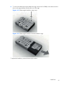
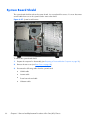
1
Maintenance & Service Guide
HP 100B All-in-One PC
© Copyright 2011 Hewlett-Packard
Development Company, L.P. The information
contained herein is subject to change
without notice.
Microsoft and Windows are trademarks of
Microsoft Corporation in the U.S. and other
countries.
The only warranties for HP products and
services are set forth in the express warranty
statements accompanying such products and
services. Nothing herein should be
construed as constituting an additional
warranty. HP shall not be liable for technical
or editorial errors or omissions contained
herein.
This document contains proprietary
information that is protected by copyright.
No part of this document may be
photocopied, reproduced, or translated to
another language without the prior written
consent of Hewlett-Packard Company.
Maintenance & Service Guide
HP Compaq 100B All-in-One PC
First Edition (January 2011)
Document Part Number: 640045-001
About This Book
WARNING! Text set off in this manner indicates that failure to follow directions could result in bodily
harm or loss of life.
CAUTION: Text set off in this manner indicates that failure to follow directions could result in damage
to equipment or loss of information.
NOTE: Text set off in this manner provides important supplemental information.
iii
iv
About This Book
Table of contents
1 Installing and Customizing the Software ........................................................................... 1
Installing the Operating System .................................................................................................. 1
Downloading Microsoft Windows Updates ................................................................................. 2
Installing or Upgrading Device Drivers (Windows systems) ............................................................ 2
Accessing Disk Image (ISO) Files ............................................................................................... 2
Protecting the Software ............................................................................................................. 3
2 Computer Setup (F10) Utility ............................................................................................. 4
Computer Setup (F10) Utilities ................................................................................................... 4
Using Computer Setup (F10) Utilities ............................................................................ 5
Computer Setup—File ................................................................................................ 6
Computer Setup—Storage .......................................................................................... 7
Computer Setup—Security .......................................................................................... 9
Computer Setup—Power .......................................................................................... 12
Computer Setup—Advanced .................................................................................... 12
3 Serial ATA (SATA) Drive Guidelines and Features ............................................................ 14
SATA Hard Drives .................................................................................................................. 14
SATA Hard Drive Cables ........................................................................................................ 14
SATA Data Cable ................................................................................................... 14
SMART ATA Drives ................................................................................................................. 15
Hard Drive Capacities ............................................................................................................ 15
4 Identifying the Chassis, Routine Care, and Disassembly Preparation ............................... 16
Chassis Designation ............................................................................................................... 16
All-in One .............................................................................................................. 16
Electrostatic Discharge Information ........................................................................................... 17
Generating Static .................................................................................................... 17
Preventing Electrostatic Damage to Equipment ............................................................ 17
Personal Grounding Methods and Equipment ............................................................. 18
Grounding the Work Area ....................................................................................... 18
v
Recommended Materials and Equipment .................................................................... 19
Operating Guidelines ............................................................................................................. 19
Routine Care ......................................................................................................................... 20
General Cleaning Safety Precautions ......................................................................... 20
Cleaning the Computer Case .................................................................................... 20
Cleaning the Keyboard ............................................................................................ 20
Cleaning the Monitor ............................................................................................... 21
Cleaning the Mouse ................................................................................................ 21
Service Considerations ........................................................................................................... 21
Tools and Software Requirements .............................................................................. 22
Screws ................................................................................................................... 22
Cables and Connectors ............................................................................................ 22
Hard Drives ............................................................................................................ 22
Lithium Coin Cell Battery .......................................................................................... 23
5 Illustrated parts catalog .................................................................................................. 24
Computer major components ................................................................................................... 24
Mass storage devices ............................................................................................................. 26
Sequential part number listing .................................................................................................. 27
6 Removal and Replacement Procedures All-in One (AIO) Chassis ...................................... 29
Preparing to Disassemble the Computer .................................................................................... 29
Rear Cover ............................................................................................................................ 30
Feet ...................................................................................................................................... 33
Stand ................................................................................................................................... 34
Optical Drive ......................................................................................................................... 36
Hard Drive ............................................................................................................................ 38
Memory ................................................................................................................................ 42
Fan ...................................................................................................................................... 45
Speakers ............................................................................................................................... 48
Webcam Module and Cable ................................................................................................... 52
Hard Drive Cable ................................................................................................................... 55
Optical Drive Cable ............................................................................................................... 57
Optical Drive Bracket ............................................................................................................. 59
Inverter Board ........................................................................................................................ 60
Power Button Board and Cable ................................................................................................ 63
System Board Shield ............................................................................................................... 66
Heat Sink (Thermal Module) .................................................................................................... 68
WLAN Module ...................................................................................................................... 69
System Board ........................................................................................................................ 72
Front Bezel ............................................................................................................................ 74
vi
Display Panel ........................................................................................................................ 76
Appendix A POST Error Messages ...................................................................................... 79
POST Numeric Codes and Text Messages ................................................................................. 80
Interpreting POST Diagnostic Front Panel LEDs and Audible Codes ............................................... 87
Appendix B Connector Pin Assignments ............................................................................. 91
Ethernet BNC ........................................................................................................................ 91
USB ...................................................................................................................................... 91
Microphone .......................................................................................................................... 91
Headphone ........................................................................................................................... 92
Line-in Audio ......................................................................................................................... 92
Line-out Audio ........................................................................................................................ 92
Appendix C Power Cord Set Requirements ......................................................................... 93
General Requirements ............................................................................................................ 93
Japanese Power Cord Requirements ......................................................................................... 93
Country-Specific Requirements ................................................................................................. 94
Index ................................................................................................................................. 95
vii
viii
1
Installing and Customizing the
Software
If your computer was not shipped with a Microsoft operating system, some portions of this
documentation do not apply. Additional information is available in online help after you install the
operating system.
NOTE: If the computer was shipped with Windows Vista or Windows 7 loaded, you will be
prompted to register the computer with HP Total Care before installing the operating system. You will
see a brief movie followed by an online registration form. Fill out the form, click the Begin button, and
follow the instructions on the screen.
CAUTION: Do not add optional hardware or third-party devices to the computer until the operating
system is successfully installed. Doing so may cause errors and prevent the operating system from
installing properly.
NOTE: Be sure there is a 10.2-cm (4-inch) clearance at the back of the unit and above the monitor to
permit the required airflow.
Installing the Operating System
The first time you turn on the computer, the operating system is installed automatically. This process
takes about 5 to 10 minutes, depending on which operating system is being installed. Carefully read
and follow the instructions on the screen to complete the installation.
CAUTION: Once the automatic installation has begun, DO NOT TURN OFF THE COMPUTER UNTIL
THE PROCESS IS COMPLETE. Turning off the computer during the installation process may damage the
software that runs the computer or prevent its proper installation.
NOTE: If the computer shipped with more than one operating system language on the hard drive, the
installation process could take up to 60 minutes.
If your computer was not shipped with a Microsoft operating system, some portions of this
documentation do not apply. Additional information is available in online help after you install the
operating system.
Installing the Operating System
1
Downloading Microsoft Windows Updates
1.
To set up your Internet connection, click Start > Internet Explorer and follow the instructions
on the screen.
2.
Once an Internet connection has been established, click the Start button.
3.
Select the All Programs menu.
4.
Click on the Windows Update link.
In Windows Vista and Windows 7, the Windows Update screen appears. Click view
available updates and make sure all critical updates are selected. Click the Install button and
follow the instructions on the screen.
In Windows XP, you will be directed to the Microsoft Windows Update Web site. If you see
one or more pop-up windows that ask you to install a program from http://www.microsoft.com,
click Yes to install the program. Follow the instructions on the Microsoft Web site to scan for
updates and install critical updates and service packs.
It is recommended that you install all of the critical updates and service packs.
5.
After the updates have been installed, Windows will prompt you to reboot the machine. Be sure to
save any files or documents that you may have open before rebooting. Then select Yes to reboot
the machine.
Installing or Upgrading Device Drivers (Windows
systems)
When installing optional hardware devices after the operating system installation is complete, you must
also install the drivers for each of the devices.
If prompted for the i386 directory, replace the path specification with C:\i386, or use the Browse
button in the dialog box to locate the i386 folder. This action points the operating system to the
appropriate drivers.
Obtain the latest support software, including support software for the operating system from
http://www.hp.com/support. Select your country and language, select Download drivers and
software (and firmware), enter the model number of the computer, and press Enter.
Accessing Disk Image (ISO) Files
There are disk image files (ISO files) included on your PC that contain the installation software for
additional software. These CD image files are located in the folder C:\SWSetup\ISOs. Each .iso file
can be burned to CD media to create an installation CD. It is recommended that these disks be created
2
Chapter 1 Installing and Customizing the Software
and the software installed in order to get the most from your PC. The software and image file names
are:
●
Corel WinDVD SD and BD – installation software for WinDVD – used to play DVD movies
●
HP Insight Diagnostics OR Vision Diagnostics – software to perform diagnostic activities on your
PC
Protecting the Software
To protect the software from loss or damage, keep a backup copy of all system software, applications,
and related files stored on the hard drive. Refer to the operating system or backup utility documentation
for instructions on making backup copies of your data files.
Protecting the Software
3
2
Computer Setup (F10) Utility
Computer Setup (F10) Utilities
Use Computer Setup (F10) Utility to do the following:
4
●
Change factory default settings.
●
Set the system date and time.
●
Set, view, change, or verify the system configuration, including settings for processor, graphics,
memory, audio, storage, communications, and input devices.
●
Modify the boot order of bootable devices such as hard drives, optical drives, or USB flash media
devices.
●
Select Post Messages Enabled or Disabled to change the display status of Power-On Self-Test
(POST) messages. Post Messages Disabled suppresses most POST messages, such as memory
count, product name, and other non-error text messages. If a POST error occurs, the error is
displayed regardless of the mode selected. To manually switch to Post Messages Enabled during
POST, press any key (except F1 through F12).
●
Enable the power-on password prompt during system restarts (warm boots) as well as during
power-on.
●
Establish a setup password that controls access to the Computer Setup (F10) Utility and the settings
described in this section.
●
Secure integrated I/O functionality, including USB, audio, or embedded NIC, so that they cannot
be used until they are unsecured.
●
Enable or disable removable media boot ability.
●
Solve system configuration errors detected but not automatically fixed during the Power-On SelfTest (POST).
●
Execute self-tests on a specified ATA hard drive (when supported by drive).
Chapter 2 Computer Setup (F10) Utility
Using Computer Setup (F10) Utilities
Computer Setup can be accessed only by turning the computer on or restarting the system. To access
the Computer Setup Utilities menu, complete the following steps:
1.
Turn on or restart the computer. If you are in Microsoft Windows, click Start > Shut Down >
Restart.
2.
As soon as the computer is turned on, press F10 before the computer boots to the operating
system to enter Computer Setup. Press Enter to bypass the title screen, if necessary.
NOTE: If you do not press F10 at the appropriate time, you must restart the computer and again
press F10 before the computer boots to the operating system to access the utility.
3.
Select your language from the list and press Enter.
4.
A choice of five headings appears in the Computer Setup Utilities menu: File, Storage, Security,
Power, and Advanced.
5.
Use the arrow (left and right) keys to select the appropriate heading. Use the arrow (up and down)
keys to select the option you want, then press Enter. To return to the Computer Setup Utilities
menu, press Esc.
6.
To apply and save changes, select File > Save Changes and Exit.
●
If you have made changes that you do not want applied, select Ignore Changes and
Exit.
●
To reset to factory settings or previously saved default settings (some models), select Apply
Defaults and Exit. This option will restore the original factory system defaults.
CAUTION: Do NOT turn the computer power OFF while the BIOS is saving the Computer Setup
(F10) changes because the CMOS could become corrupted. It is safe to turn off the computer only after
exiting the F10 Setup screen.
Table 2-1 Computer Setup (F10) Utility
Heading
Table
File
Table 2-2 Computer Setup—File on page 6
Storage
Table 2-3 Computer Setup—Storage on page 7
Security
Table 2-4 Computer Setup—Security on page 9
Power
Table 2-5 Computer Setup—Power on page 12
Advanced
Table 2-6 Computer Setup—Advanced on page 12
Computer Setup (F10) Utilities
5
Computer Setup—File
NOTE: Support for specific Computer Setup options may vary depending on the hardware
configuration.
Table 2-2 Computer Setup—File
6
Option
Description
System Information
Lists:
●
Product name
●
SKU number (some models)
●
Processor type/speed/stepping/cache size
●
Installed memory size/speed, number of channels (single or dual) (if applicable)
●
Integrated MAC address for embedded, enabled NIC (if applicable)
●
System BIOS (includes family name and version)
●
Chassis serial number
About
Displays copyright notice.
Set Time and Date
Allows you to set system time and date.
Apply Defaults and
Exit
Applies the currently selected default settings and clears any established passwords.
Ignore Changes
and Exit
Exits Computer Setup without applying or saving any changes.
Save Changes and
Exit
Saves changes to system configuration or default settings and exits Computer Setup.
Chapter 2 Computer Setup (F10) Utility
Computer Setup—Storage
NOTE: Support for specific Computer Setup options may vary depending on the hardware
configuration.
Table 2-3 Computer Setup—Storage
Option
Description
Device
Configuration
Lists all installed BIOS-controlled storage devices.
When a device is selected, detailed information and options are displayed. The following options
may be presented:
Hard Disk: Size, model, firmware, serial number, connector color, SMART, emulation type.
Emulation type has the following choices:
●
None (prevents BIOS data accesses and disables it as a boot device)
●
Hard Disk (treated as a hard disk)
CD-ROM: Model, firmware, serial number. No emulation options available.
Storage Options
SATA Emulation
Allows you to choose how the SATA controller and devices are accessed by the operating system.
There are two supported options: AHCI and IDE.
AHCI (default option) - Allows operating systems with AHCI device drivers loaded to take
advantage of more advanced features of the SATA controller.
IDE - This is the most backwards-compatible setting of the two options. Operating systems usually do
not require additional driver support in IDE mode.
NOTE: The AHCI device driver must be installed prior to attempting to boot from an AHCI
volume. If you attempt to boot from an AHCI volume without the required device driver installed, the
system will crash (blue screen).
Computer Setup (F10) Utilities
7
Table 2-3 Computer Setup—Storage (continued)
DPS Self-Test
Allows you to execute self-tests on ATA hard drives capable of performing the Drive Protection
System (DPS) self-tests.
NOTE: This selection will only appear when at least one drive capable of performing the DPS selftests is attached to the system.
Boot Order
Allows you to:
●
Specify the order in which attached devices (such as a USB flash media device, hard drive,
optical drive, or network interface card) are checked for a bootable operating system image.
Each device on the list may be individually excluded from or included for consideration as a
bootable operating system source.
●
Specify the order of attached hard drives. The first hard drive in the order will have priority in
the boot sequence and will be recognized as drive C (if any devices are attached).
NOTE: MS-DOS drive lettering assignments may not apply after a non-MS-DOS operating system
has started.
Shortcut to Temporarily Override Boot Order
To boot one time from a device other than the default device specified in Boot Order, restart the
computer and press F9 before the computer boots to the operating system. After POST is completed,
a list of bootable devices is displayed. Use the arrow keys to select the preferred bootable device
and press Enter. The computer then boots from the selected non-default device for this one time.
8
Chapter 2 Computer Setup (F10) Utility
Computer Setup—Security
NOTE: Support for specific Computer Setup options may vary depending on the hardware
configuration.
Table 2-4 Computer Setup—Security
Option
Description
Setup Password
Allows you to set and enable a setup (administrator) password.
NOTE: If the setup password is set, it is required to change Computer Setup options, flash the
ROM, and make changes to certain plug and play settings under Windows.
See the Desktop Management Guide for more information.
Power-On
Password
Allows you to set and enable a power-on password. The power-on password prompt appears after
a power cycle. If the user does not enter the correct power-on password, the unit will not boot.
NOTE: This password does not appear on warm boots , such as Ctrl+Alt+Delete or Restart
from Windows, unless enabled in Password Options (see below).
See the Desktop Management Guide for more information.
Device Security
USB Security
Allows you to set Device Available/Device Hidden for:
●
System audio
●
Network controllers (some models)
●
SATA0
●
SATA1
Allows you to enable or disable groups of USB ports or individual USB ports:
●
●
●
Front USB Ports
◦
USB Port 11
◦
USB Port 13
Rear USB Ports
◦
USB Port 0
◦
USB Port 1
◦
USB Port 4
◦
USB Port 9
Accessory USB Ports
◦
USB Port 3
◦
USB Port 12
Slot Security
Allows you to disable or enable the mini card slot
Network Service
Boot
Enables/disables the computer’s ability to boot from an operating system installed on a network
server.
Computer Setup (F10) Utilities
9
Table 2-4 Computer Setup—Security (continued)
System IDs
Shows:
●
Product name
●
Chassis serial number or Universal Unique Identifier (UUID) number. The UUID can only be
updated if the current chassis serial number is invalid. (These ID numbers are normally set in
the factory and are used to uniquely identify the system.)
●
SKU number
●
Family name
●
Feature
Allows you to set:
●
10
Keyboard locale setting (for example, English or German) for System ID entry.
Chapter 2 Computer Setup (F10) Utility
Table 2-4 Computer Setup—Security (continued)
System Security
(some models: these
options are hardware
dependent)
Data Execution Prevention (some models) (enable/disable) - Helps prevent operating system security
breaches.
PAVP (Models with Blu-ray drives) (disabled/min/max) - PAVP enables the Protected Audio Video
Path in the Chipset. This may allow viewing of some protected high definition content that would
otherwise be prohibited from playback. Selecting Max will assign 96 Megabytes of system memory
exclusively to PAVP.
Virtualization Technology (some models) (enable/disable) - Controls the virtualization features of the
processor. Changing this setting requires turning the computer off and then back on.
Virtualization Technology Directed I/O (some models) (enable/disable) - Controls virtualization
DMA remapping features of the chipset. Changing this setting requires turning the computer off and
then back on.
Trusted Execution Technology (some models) (enable/disable) - Controls the underlying processor
and chipset features needed to support a virtual appliance. Changing this setting requires turning
the computer off and then back on. To enable this feature you must enable the following features:
●
Embedded Security Device Support
●
Virtualization Technology
●
Virtualization Technology Directed I/O
Embedded Security Device Support (some models) (enable/disable) - Permits activation and
deactivation of the Embedded Security Device. Changing this setting requires turning the computer
off and then back on.
NOTE:
●
To configure the Embedded Security Device, a Setup password must be set.
Reset to Factory Settings (some models) (Do not reset/Reset) - Resetting to factory defaults will
erase all security keys. Changing this setting requires turning the computer off and then back
on.
CAUTION: The embedded security device is a critical component of many security schemes.
Erasing the security keys will prevent access to data protected by the Embedded Security
Device. Choosing Reset to Factory Settings may result in significant data loss.
System Security
(continued)
OS management of Embedded Security Device (some models) (enable/disable) - This option allows
the user to limit operating system control of the Embedded Security Device. Changing this setting
requires turning the computer off and then back on. This option allows the user to limit OS control of
the Embedded Security Device.
●
Reset of Embedded Security Device through OS (some models) (enable/disable) - This option
allows the user to limit the operating system ability to request a Reset to Factory Settings of the
Embedded Security Device. Changing this setting requires turning the computer off and then
back on.
NOTE:
To enable this option, a Setup password must be set.
Button Retask Password Protection (disable/enable) - Controls whether or not the Setup password
must be provided to WMI methods used to re-task the function of the side panel buttons.
Power Button (enable/disable) - Allows you to disable or enable the power button.
Consumer IR Power Button (enable/disable) - Controls whether or not the BIOS will respond to
Remote Control power button presses. This does not affect the Remote Control power button
operation in Windows.
Optical Drive Eject Button (enable/disable) - Allows you to disable or enable the optical drive eject
button. Disabling the eject button does not disable software control of the eject function inside
Windows.
Computer Setup (F10) Utilities
11
Computer Setup—Power
NOTE: Support for specific Computer Setup options may vary depending on the hardware
configuration.
Table 2-5 Computer Setup—Power
Option
Description
Hardware Power
Management
SATA Power Management—Enables or disables the SATA bus and/or device power management.
S5 Maximum Power Savings—Turns off power to all nonessential hardware when system is off to
meet EUP Lot 6 requirement of less than 1 Watt power usage. Enabling this feature will disable any
wake events and management devices while in S5.
Thermal
Fan idle mode—Displays CPU fan speed.
Computer Setup—Advanced
NOTE: Support for specific Computer Setup options may vary depending on the hardware
configuration.
Table 2-6 Computer Setup—Advanced
Option
Heading
Power-On Options
Allows you to set:
●
POST messages (enable/disable). Suppresses most POST messages, such as memory count,
product name, and other non-error text messages. If a POST error occurs, the error is
displayed regardless of the mode selected.
●
After Power Loss (off/on/previous state): Setting this option to:
◦
Off—causes the computer to remain powered off when power is restored.
◦
On—causes the computer to power on automatically as soon as power is restored.
◦
Previous state—causes the computer to power on automatically as soon as power is
restored, if it was on when power was lost.
NOTE: If you turn off power to the computer using the switch on a power strip, you will not be
able to use the suspend/sleep feature or the Remote Management features.
●
12
POST Delay (None, 5, 10 15, or 20 seconds). Enabling this feature will add a user-specified
delay to the POST process. This delay is sometimes needed for hard disks on some PCI cards
that spin up very slowly, so slowly that they are not ready to boot by the time POST is finished.
The POST delay also gives you more time to select F10 to enter Computer (F10) Setup.
BIOS Power-On
Allows you to set the computer to turn on automatically at a time you specify.
Bus Options
On some models, allows you to enable or disable:
●
PCI SERR# Generation.
●
PCI VGA Palette Snooping, which sets the VGA palette snooping bit in PCI configuration
space; only needed when more than one graphics controller is installed.
Chapter 2 Computer Setup (F10) Utility
Table 2-6 Computer Setup—Advanced (continued)
Device Options
Allows you to set:
●
Num Lock State at Power-On (off/on).
●
Internal Speaker (some models) (does not affect external speakers).
●
NIC Option ROM Download (PXE, Disable, iSCSI). The BIOS contains an embedded NIC
option ROM to allow the unit to boot through the network to a PXE server. This is typically used
to download a corporate image to a hard drive. The NIC option ROM takes up memory space
below 1MB commonly referred to as DOS Compatibility Hole (DCH) space. This space is
limited. This F10 option will allow users to disable the downloading of this embedded NIC
option ROM thus giving more DCH space for additional PCI cards which may need option
ROM space. The default will be to have the NIC PXE option-ROM-enabled.
Management
Devices
Only displayed in the Advanced Menu when the BIOS detects multiple management options. This
option is for installed NIC cards that support ASF or DASH. Use the Management Devices menu to
select if the BIOS management operations will be through the embedded solution or one of the
installed NIC cards.
Management
Operations
Allows you to set:
●
MEBx Setup Prompt (enable/disable)
●
Unprovision AMT on next boot
●
SOL Terminal Emulation Mode
●
SOL Local Keyboard (enable/disable)
Computer Setup (F10) Utilities
13
3
Serial ATA (SATA) Drive Guidelines
and Features
NOTE: HP only supports the use of SATA hard drives on these models of computer. No Parallel ATA
(PATA) drives are supported.
SATA Hard Drives
Serial ATA Hard Drive Characteristics
Number of pins/conductors in data cable
7/7
Number of pins in power cable
15
Maximum data cable length
39.37 in (100 cm)
Data interface voltage differential
400-700 mV
Drive voltages
3.3 V, 5 V, 12 V
Jumpers for configuring drive
N/A
Data transfer rate
3.0 Gb/s
SATA Hard Drive Cables
SATA Data Cable
Always use an HP approved SATA 3.0 Gb/s cable as it is fully backwards compatible with the SATA
1.5 Gb/s drives.
Current HP desktop products ship with SATA 3.0 Gb/s hard drives.
SATA data cables are susceptible to damage if overflexed. Never crease a SATA data cable and never
bend it tighter than a 30 mm (1.18 in) radius.
The SATA data cable is a thin, 7-pin cable designed to transmit data for only a single drive.
14
Chapter 3 Serial ATA (SATA) Drive Guidelines and Features
SMART ATA Drives
The Self Monitoring Analysis and Recording Technology (SMART) ATA drives for the HP Personal
Computers have built-in drive failure prediction that warns the user or network administrator of an
impending failure or crash of the hard drive. The SMART drive tracks fault prediction and failure
indication parameters such as reallocated sector count, spin retry count, and calibration retry count. If
the drive determines that a failure is imminent, it generates a fault alert.
Hard Drive Capacities
The combination of the file system and the operating system used in the computer determines the
maximum usable size of a drive partition. A drive partition is the largest segment of a drive that may be
properly accessed by the operating system. A single hard drive may therefore be subdivided into a
number of unique drive partitions in order to make use of all of its space.
Because of the differences in the way that drive sizes are calculated, the size reported by the operating
system may differ from that marked on the hard drive or listed in the computer specification. Drive size
calculations by drive manufacturers are bytes to the base 10 while calculations by Microsoft are bytes
to the base 2.
Drive/Partition Capacity Limits
Maximum Size
File System
Controller Type
Operating System
Partition
Drive
FAT 32
ATA
Windows 7
32 GB
2 TB
NTFS
ATA
Windows 7
2 TB
2 TB
SMART ATA Drives
15
4
Identifying the Chassis, Routine
Care, and Disassembly Preparation
This chapter provides general service information for the computer. Adherence to the procedures and
precautions described in this chapter is essential for proper service.
CAUTION: When the computer is plugged into an AC power source, voltage is always applied to
the system board. You must disconnect the power cord from the power source before opening the
computer to prevent system board or component damage.
Chassis Designation
An all-in one form factor is available.
All-in One
16
Chapter 4 Identifying the Chassis, Routine Care, and Disassembly Preparation
Electrostatic Discharge Information
A sudden discharge of static electricity from your finger or other conductor can destroy static-sensitive
devices or microcircuitry. Often the spark is neither felt nor heard, but damage occurs. An electronic
device exposed to electrostatic discharge (ESD) may not appear to be affected at all and can work
perfectly throughout a normal cycle. The device may function normally for a while, but it has been
degraded in the internal layers, reducing its life expectancy.
Networks built into many integrated circuits provide some protection, but in many cases, the discharge
contains enough power to alter device parameters or melt silicon junctions.
Generating Static
The following table shows that:
●
Different activities generate different amounts of static electricity.
●
Static electricity increases as humidity decreases.
Relative Humidity
Event
55%
40%
10%
Walking across carpet
7,500 V
15,000 V
35,000 V
Walking across vinyl floor
3,000 V
5,000 V
12,000 V
Motions of bench worker
400 V
800 V
6,000 V
Removing DIPs* from plastic tube
400 V
700 V
2,000 V
Removing DIPs* from vinyl tray
2,000 V
4,000 V
11,500 V
Removing DIPs* from Styrofoam
3,500 V
5,000 V
14,500 V
Removing bubble pack from PCB
7,000 V
20,000 V
26,500 V
Packing PCBs in foam-lined box
5,000 V
11,000 V
21,000 V
*These are then multi-packaged inside plastic tubes, trays, or Styrofoam.
NOTE: 700 volts can degrade a product.
Preventing Electrostatic Damage to Equipment
Many electronic components are sensitive to ESD. Circuitry design and structure determine the degree
of sensitivity. The following packaging and grounding precautions are necessary to prevent damage to
electric components and accessories.
●
To avoid hand contact, transport products in static-safe containers such as tubes, bags, or boxes.
●
Protect all electrostatic parts and assemblies with conductive or approved containers or
packaging.
Electrostatic Discharge Information
17
●
Keep electrostatic sensitive parts in their containers until they arrive at static-free stations.
●
Place items on a grounded surface before removing them from their container.
●
Always be properly grounded when touching a sensitive component or assembly.
●
Avoid contact with pins, leads, or circuitry.
●
Place reusable electrostatic-sensitive parts from assemblies in protective packaging or conductive
foam.
Personal Grounding Methods and Equipment
Use the following equipment to prevent static electricity damage to equipment:
●
Wrist straps are flexible straps with a maximum of one-megohm ± 10% resistance in the ground
cords. To provide proper ground, a strap must be worn snug against bare skin. The ground cord
must be connected and fit snugly into the banana plug connector on the grounding mat or
workstation.
●
Heel straps/Toe straps/Boot straps can be used at standing workstations and are
compatible with most types of shoes or boots. On conductive floors or dissipative floor mats, use
them on both feet with a maximum of one-megohm ± 10% resistance between the operator and
ground.
Static Shielding Protection Levels
Method
Voltage
Antistatic plastic
1,500
Carbon-loaded plastic
7,500
Metallized laminate
15,000
Grounding the Work Area
To prevent static damage at the work area, use the following precautions:
18
●
Cover the work surface with approved static-dissipative material. Provide a wrist strap connected
to the work surface and properly grounded tools and equipment.
●
Use static-dissipative mats, foot straps, or air ionizers to give added protection.
●
Handle electrostatic sensitive components, parts, and assemblies by the case or PCB laminate.
Handle them only at static-free work areas.
●
Turn off power and input signals before inserting and removing connectors or test equipment.
●
Use fixtures made of static-safe materials when fixtures must directly contact dissipative surfaces.
●
Keep work area free of nonconductive materials such as ordinary plastic assembly aids and
Styrofoam.
●
Use field service tools, such as cutters, screwdrivers, and vacuums, that are conductive.
Chapter 4 Identifying the Chassis, Routine Care, and Disassembly Preparation
Recommended Materials and Equipment
Materials and equipment that are recommended for use in preventing static electricity include:
●
Antistatic tape
●
Antistatic smocks, aprons, or sleeve protectors
●
Conductive bins and other assembly or soldering aids
●
Conductive foam
●
Conductive tabletop workstations with ground cord of one-megohm +/- 10% resistance
●
Static-dissipative table or floor mats with hard tie to ground
●
Field service kits
●
Static awareness labels
●
Wrist straps and footwear straps providing one-megohm +/- 10% resistance
●
Material handling packages
●
Conductive plastic bags
●
Conductive plastic tubes
●
Conductive tote boxes
●
Opaque shielding bags
●
Transparent metallized shielding bags
●
Transparent shielding tubes
Operating Guidelines
To prevent overheating and to help prolong the life of the computer:
●
Keep the computer away from excessive moisture, direct sunlight, and extremes of heat and cold.
●
Operate the computer on a sturdy, level surface. Leave a 10.2-cm (4-inch) clearance on all vented
sides of the computer and above the monitor to permit the required airflow.
●
Never restrict the airflow into the computer by blocking any vents or air intakes. Do not place the
keyboard, with the keyboard feet down, directly against the front of the desktop unit as this also
restricts airflow.
●
Occasionally clean the air vents on all vented sides of the computer. Lint, dust, and other foreign
matter can block the vents and limit the airflow. Be sure to unplug the computer before cleaning
the air vents.
●
Never operate the computer with the cover removed.
Operating Guidelines
19
●
Do not place computers so near each other that they are subject to each other’s re-circulated or
preheated air.
●
Keep liquids away from the computer and keyboard.
●
Never cover the ventilation slots on the monitor with any type of material.
●
Install or enable power management functions of the operating system or other software, including
sleep states.
Routine Care
General Cleaning Safety Precautions
1.
Never use solvents or flammable solutions to clean the computer.
2.
Never immerse any parts in water or cleaning solutions; apply any liquids to a clean cloth and
then use the cloth on the component.
3.
Always unplug the computer when cleaning with liquids or damp cloths.
4.
Always unplug the computer before cleaning the keyboard, mouse, or air vents.
5.
Disconnect the keyboard before cleaning it.
6.
Wear safety glasses equipped with side shields when cleaning the keyboard.
Cleaning the Computer Case
Follow all safety precautions in General Cleaning Safety Precautions on page 20 before cleaning the
computer.
To clean the computer case, follow the procedures described below:
●
To remove light stains or dirt, use plain water with a clean, lint-free cloth or swab.
●
For stronger stains, use a mild dishwashing liquid diluted with water. Rinse well by wiping it with
a cloth or swab dampened with clear water.
●
For stubborn stains, use isopropyl (rubbing) alcohol. No rinsing is needed as the alcohol will
evaporate quickly and not leave a residue.
●
After cleaning, always wipe the unit with a clean, lint-free cloth.
●
Occasionally clean the air vents on the computer. Lint and other foreign matter can block the vents
and limit the airflow.
Cleaning the Keyboard
Follow all safety precautions in General Cleaning Safety Precautions on page 20 before cleaning the
keyboard.
20
Chapter 4 Identifying the Chassis, Routine Care, and Disassembly Preparation
To clean the tops of the keys or the keyboard body, follow the procedures described in Cleaning the
Computer Case on page 20.
When cleaning debris from under the keys, review all rules in General Cleaning Safety Precautions
on page 20 before following these procedures:
CAUTION: Use safety glasses equipped with side shields before attempting to clean debris from
under the keys.
●
Visible debris underneath or between the keys may be removed by vacuuming or shaking.
●
Canned, pressurized air may be used to clean debris from under the keys. Caution should be used
as too much air pressure can dislodge lubricants applied under the wide keys.
●
If you remove a key, use a specially designed key puller to prevent damage to the keys. This tool
is available through many electronic supply outlets.
CAUTION: Never remove a wide leveled key (like the space bar) from the keyboard. If these
keys are improperly removed or installed, the keyboard may not function properly.
●
Cleaning under a key may be done with a swab moistened with isopropyl alcohol and squeezed
out. Be careful not to wipe away lubricants necessary for proper key functions. Use tweezers to
remove any fibers or dirt in confined areas. Allow the parts to air dry before reassembly.
Cleaning the Monitor
●
Wipe the monitor screen with a clean cloth moistened with water or with a towelette designed for
cleaning monitors. Do not use sprays or aerosols directly on the screen; the liquid may seep into
the housing and damage a component. Never use solvents or flammable liquids on the monitor.
●
To clean the monitor body follow the procedures in Cleaning the Computer Case on page 20.
Cleaning the Mouse
Before cleaning the mouse, ensure that the power to the computer is turned off.
●
Clean the mouse ball by first removing the retaining plate and the ball from the housing. Pull out
any debris from the ball socket and wipe the ball with a clean, dry cloth before reassembly.
●
To clean the mouse body, follow the procedures in Cleaning the Computer Case on page 20.
Service Considerations
Listed below are some of the considerations that you should keep in mind during the disassembly and
assembly of the computer.
Service Considerations
21
Tools and Software Requirements
To service the computer, you need the following:
●
Torx T-15 screwdriver (HP screwdriver with bits, PN 161946-001)
●
Flat-bladed screwdriver (may sometimes be used in place of the Torx screwdriver)
●
Phillips #2 screwdriver
●
Diagnostics software
●
HP tamper-resistant T-15 wrench (Smart Cover FailSafe Key, PN 166527-001) or HP tamperresistant bits (Smart Cover FailSafe Key, PN 166527-002)
Screws
The screws used in the computer are not interchangeable. They may have standard or metric threads
and may be of different lengths. If an incorrect screw is used during the reassembly process, it can
damage the unit. HP strongly recommends that all screws removed during disassembly be kept with the
part that was removed, then returned to their proper locations.
CAUTION: As each subassembly is removed from the computer, it should be placed away from the
work area to prevent damage.
Cables and Connectors
Most cables used throughout the unit are flat, flexible cables. These cables must be handled with care
to avoid damage. Apply only the tension required to seat or unseat the cables during insertion or
removal from the connector. Handle cables by the connector whenever possible. In all cases, avoid
bending or twisting the cables, and ensure that the cables are routed in such a way that they cannot be
caught or snagged by parts being removed or replaced.
CAUTION: When servicing this computer, ensure that cables are placed in their proper location
during the reassembly process. Improper cable placement can damage the computer.
Hard Drives
Handle hard drives as delicate, precision components, avoiding all physical shock and vibration. This
applies to failed drives as well as replacement spares.
22
●
If a drive must be mailed, place the drive in a bubble-pack mailer or other suitable protective
packaging and label the package “Fragile: Handle With Care.”
●
Do not remove hard drives from the shipping package for storage. Keep hard drives in their
protective packaging until they are actually mounted in the CPU.
●
Avoid dropping drives from any height onto any surface.
●
If you are inserting or removing a hard drive, turn off the computer. Do not remove a hard drive
while the computer is on or in standby mode.
Chapter 4 Identifying the Chassis, Routine Care, and Disassembly Preparation
●
Before handling a drive, ensure that you are discharged of static electricity. While handling a
drive, avoid touching the connector. For more information about preventing electrostatic damage,
refer to Electrostatic Discharge Information on page 17
●
Do not use excessive force when inserting a drive.
●
Avoid exposing a hard drive to liquids, temperature extremes, or products that have magnetic
fields such as monitors or speakers.
Lithium Coin Cell Battery
The battery that comes with the computer provides power to the real-time clock and has a minimum
lifetime of about three years.
See the appropriate removal and replacement chapter for the chassis you are working on in this guide
for instructions on the replacement procedures.
WARNING! This computer contains a lithium battery. There is a risk of fire and chemical burn if the
battery is handled improperly. Do not disassemble, crush, puncture, short external contacts, dispose in
water or fire, or expose it to temperatures higher than 140ºF (60ºC). Do not attempt to recharge the
battery.
NOTE: Batteries, battery packs, and accumulators should not be disposed of together with the
general household waste. In order to forward them to recycling or proper disposal, please use the
public collection system or return them to HP, their authorized partners, or their agents.
Service Considerations
23
5
Illustrated parts catalog
Computer major components
24
Chapter 5 Illustrated parts catalog
Item
Description
(1)
System board (includes AMD processor)
(2)
Spare part number
Dual core processor
644692-001
Single core processor
644693-001
Inverter
For use with LG displays
646797-001
For use with Samsung/CMI displays
646796-001
(3)
Webcam module cable
646786-001
(4)
Power button board
not spared
(5)
WLAN module (802.11a/b/g/n)
634906-001
(6)
Feet
Right foot
646784-001
Left foot
646785-001
(7)
Optical drive bracket
646805-001
(8)
Fan
646798-001
(9)
Front bezel
646780-001
(10)
Hard drive cable
646789-001
(11)
Optical drive cable
646790-001
(12)
Heat sink assembly (thermal module) (includes replacement thermal material)
646799-001
(13)
Power button board cable
646782-001
(14)
WLAN module antenna cable
646806-001
(15)
Stand
646783-001
(16)
Rear cover
646781-001
(17)
Speakers
Right speaker
646792-001
Left speaker
646793-001
Display panel, 20-inch (not illustrated)
LG
646795-001
Samsung/CMI
646796-001
Optical drive (does not include bezel; not illustrated)
8X DVD±RW SuperMulti DL Drive with LightScribe without bezel
619238-001
8X DVD±RW SuperMulti DL Drive with LightScribe with bezel
646803-001
Optical drive bezel (not illustrated)
646804-001
Computer major components
25
Item
Description
Spare part number
Hard drive (not illustrated)
750-GB
632938-001
500-GB
621421-001
250-GB
621419-001
Hard drive grommets (screws)
646791-001
Memory modules (PC3-10600, 1333-MHz; not illustrated)
4-GB
646801-001
2-GB
646800-001
1-GB
647448-001
AC adapter 90W (external; not illustrated)
For use worldwide
646778-001
For use in India
646779-001
Keyboard, USB (not illustrated)
Brazil
537924-201
Latin America
537924-161
United States
537924-001
Mouse, USB, optical. Portia (not illustrated)
596410-001
Screw Kit (not illustrated)
647523-001
Power cords (not illustrated)
For use in Argentina
403811-201
For use in Brazil
490371-202
For use in Italy
246959-061
For use in the United States
246959-001
Mass storage devices
Description
Spare part number
Optical drives
8X DVD±RW SuperMulti DL Drive with LightScribe without bezel
619238-001
8X DVD±RW SuperMulti DL Drive with LightScribe with bezel
646803-001
Hard drive
750-GB
26
Chapter 5 Illustrated parts catalog
632938-001
Description
Spare part number
500-GB
621421-001
250-GB
621419-001
Hard drive grommets (screws)
646791-001
Sequential part number listing
Spare part
number
Description
246959-001
Power cord for use in the United States
246959-061
Power cord for use in Italy
403811-201
Power cord for use in Argentina
490371-202
Power cord for use in Brazil
537924-001
USB keyboard for use in the United States
537924-161
USB keyboard for use in Latin America
537924-201
USB keyboard for use in Brazil
596410-001
Mouse, USB, Portia
619238-001
8X DVD±RW SuperMulti DL Drive with LightScribe without bezel
621419-001
Hard drive, 250 GB
621421-001
Hard drive, 500 GB
632938-001
Hard drive, 750 GB
634906-001
WLAN module (802.11a/b/g/n)
644692-001
System board with AMD dual core processor
644693-001
System board with AMD single core processor
646778-001
AC adapter, 90 W, for use worldwide (external)
646779-001
AC adapter, 90 W, for use in India (external)
646780-001
Front bezel
646781-001
Rear cover
646782-001
Power button board cable
646783-001
Stand
646784-001
Foot, right
646785-001
Foot, left
Sequential part number listing
27
28
Spare part
number
Description
646786-001
Webcam module cable
646787-001
LVDS cable
646791-001
Hard drive grommets (screws)
646792-001
Speaker, right
646793-001
Speaker, left
646794-001
Display, 20-inch, Samsung/CMI
646795-001
Display, 20-inch, LG
646796-001
Inverter for use with Samsung/CMI displays
646797-001
Inverter for use with LG displays
646798-001
Fan
646799-001
Heat sink assembly (thermal module) (includes replacement thermal material)
646800-001
2-GB memory module (PC3-10600, 1333-MHz)
646801-001
4-GB memory module (PC3-10600, 1333-MHz)
646803-001
8X DVD±RW SuperMulti DL Drive with LightScribe with bezel
646804-001
Optical drive bezel
646805-001
Optical drive bracket
646806-001
WLAN module antenna cable
647448-001
1-GB memory module
647523-001
Screw Kit
Chapter 5 Illustrated parts catalog
6
Removal and Replacement
Procedures All-in One (AIO) Chassis
The following sections provide information about disassembling various components of the HP Pro Allin-One.
Preparing to Disassemble the Computer
To avoid injury and equipment damage, always complete the following steps in order, when opening
the HP Pro All-in-One.
1.
Remove all media (CD, DVD, etc.) from the computer.
2.
Shut down the computer.
3.
After the system has completely shut down, disconnect the power adapter from the back of the
computer.
4.
Disconnect all other attached cables from the back of the computer.
5.
Place the computer face down on a soft flat surface. HP recommends that you set down a blanket,
towel, or other soft cloth to protect the touch screen surface from scratches or other damage.
WARNING! Beware of sharp edges inside the chassis.
Preparing to Disassemble the Computer
29
Rear Cover
Description
Spare part number
Rear cover
646781-001
The computer has one main cover on the back. Remove it to gain access to internal components.
To remove the rear cover:
1.
Prepare the computer for disassembly (see Preparing to Disassemble the Computer on page 29).
2.
Lift the stand.
Figure 6-1 Lifting the stand
30
Chapter 6 Removal and Replacement Procedures All-in One (AIO) Chassis
3.
Remove the five Torx T15M3.0x8.0 screws that secure the rear cover to the computer.
Figure 6-2 Removing the rear cover screws
4.
Use a flat tool to pry open the slots on the bottom of the computer.
Figure 6-3 Prying the rear cover loose
Rear Cover
31
5.
Lift the rear cover off the computer.
Figure 6-4 Removing the rear cover
To replace the rear cover, reverse the removal procedures.
32
Chapter 6 Removal and Replacement Procedures All-in One (AIO) Chassis
Feet
Description
Spare part number
Foot, right
646784-001
Foot, left
646785-001
Each foot is connected to the computer with one screw. The top of the foot is positioned under the
display panel bracket. You must slide the foot out from under the bracket to remove it, and place it
back under the bracket to install it.
To remove the feet:
1.
Prepare the computer for disassembly (see Preparing to Disassemble the Computer on page 29).
2.
Remove the rear cover (see Rear Cover on page 30).
3.
For each foot, remove the Torx T15 3.0x6.0 screw (1) that secures the foot to the computer.
4.
Slide the foot away out from under the display panel bracket and away from the computer (2).
Figure 6-5 Removing the feet (right foot shown)
To replace the feet, reverse the removal procedures.
When reinstalling a foot, make sure you slide the top of the foot under the display panel bracket before
securing the screw.
Feet
33
Stand
Description
Spare part number
Stand
646783-001
The stand is secured with four screws.
To remove the stand:
1.
Prepare the computer for disassembly (see Preparing to Disassemble the Computer on page 29).
2.
Remove the rear cover (see Rear Cover on page 30).
3.
Remove the four Torx T15M4.0x8.0 screws that secure the stand to the rear cover.
Figure 6-6 Removing the stand screws
34
Chapter 6 Removal and Replacement Procedures All-in One (AIO) Chassis
4.
Lift the stand off the cover.
Figure 6-7 Removing the stand
To replace the stand, reverse the removal procedures.
Stand
35
Optical Drive
Description
Spare part number
8X DVD±RW SuperMulti DL Drive with LightScribe without bezel
619238-001
8X DVD±RW SuperMulti DL Drive with LightScribe with bezel
646803-001
Optical drive bezel
646804-001
The optical drive is located under the rear cover on the left side of the computer (when viewed from
behind). It is secured with one screw.
Figure 6-8 Optical drive location
To remove the optical drive:
36
1.
Prepare the computer for disassembly (see Preparing to Disassemble the Computer on page 29).
2.
Remove the rear cover (see Rear Cover on page 30).
Chapter 6 Removal and Replacement Procedures All-in One (AIO) Chassis
3.
Loosen the captive screw that secures the optical drive to the computer.
Figure 6-9 Loosening the drive screw
4.
Insert a tool into the slot to push the drive out of the bay, and then slide the drive out of the
computer.
Figure 6-10 Removing the optical drive
To install an optical drive, reverse the removal procedures.
Optical Drive
37
Hard Drive
Description
Spare part number
750-GB
632938-001
500-GB
621421-001
250-GB
621419-001
Hard drive grommets (screws)
646791-001
The hard drive is located under the rear cover on the left side of the computer (when viewed from
behind). The drive is secured with one captive screw and is housed in a removable cage.
Figure 6-11 Hard drive location
To remove the hard drive:
38
1.
Prepare the computer for disassembly (see Preparing to Disassemble the Computer on page 29).
2.
Remove the rear cover (see Rear Cover on page 30).
Chapter 6 Removal and Replacement Procedures All-in One (AIO) Chassis
3.
Loosen the captive screw that secures the drive to the computer.
Figure 6-12 Loosening the hard drive screw
4.
Slide the drive to the left to disconnect the cables.
Figure 6-13 Sliding the hard drive to disconnect the cables
Hard Drive
39
5.
Using the drive cage handle, lift the drive out of the computer.
Figure 6-14 Removing the hard drive from the computer
40
Chapter 6 Removal and Replacement Procedures All-in One (AIO) Chassis
6.
To remove the hard drive from the hard drive cage, remove the four Phillips screws that secure the
drive to the cage, and then slide the drive out of the cage.
Figure 6-15 Removing the hard drive cage screws
Figure 6-16 Removing the hard drive from the hard drive cage
To replace the hard drive, reverse the removal procedures.
Hard Drive
41
Memory
Description
Spare part number
4-GB
646801-001
2-GB
646800-001
1-GB
647448-001
Memory modules are located on the right side of the computer (when viewed from behind) under the
memory cover. The computer has two memory slots.
Figure 6-17 Memory location
To remove a memory module:
42
1.
Prepare the computer for disassembly (see Preparing to Disassemble the Computer on page 29).
2.
Remove the rear cover (see Rear Cover on page 30).
Chapter 6 Removal and Replacement Procedures All-in One (AIO) Chassis
3.
Loosen the memory cover screw.
Figure 6-18 Removing the memory cover screw
4.
Lift the memory cover off the computer.
Figure 6-19 Removing the memory cover
Memory
43
5.
Open both latches of the memory module socket, and then remove the memory module from the
socket.
Figure 6-20 Removing the memory module
Figure 6-21 Removing the memory module
NOTE: If you are removing both cards, you must remove the upper one before removing the
lower one.
To install a memory module, reverse the removal procedures.
44
Chapter 6 Removal and Replacement Procedures All-in One (AIO) Chassis
Fan
Description
Spare part number
Fan
646798-001
The fan is located at the top of the computer.
Figure 6-22 Fan location
To remove the fan:
1.
Prepare the computer for disassembly (see Preparing to Disassemble the Computer on page 29).
2.
Remove the rear cover (see Rear Cover on page 30).
Fan
45
3.
Disconnect the fan cable from the system board connector.
Figure 6-23 Disconnecting the fan cable
4.
Remove the four Phillips PM25x60 screws that secure the fan to the computer.
Figure 6-24 Removing the fan screws
46
Chapter 6 Removal and Replacement Procedures All-in One (AIO) Chassis
5.
Lift the fan out of the computer.
Figure 6-25 Removing the fan
To install the fan, reverse the removal procedures.
Fan
47
Speakers
Description
Spare part number
Speaker, right
646792-001
Speaker, left
646793-001
The speakers are located at the bottom of the computer. Two screws secure each speaker. Each
speaker connects to the system board..
Figure 6-26 Speaker location
To remove the speakers:
48
1.
Prepare the computer for disassembly (see Preparing to Disassemble the Computer on page 29).
2.
Remove the rear cover (see Rear Cover on page 30).
Chapter 6 Removal and Replacement Procedures All-in One (AIO) Chassis
3.
Remove two Phillips PM30x100 screws that secure each speaker to the computer.
Figure 6-27 Removing the left speaker screws
Figure 6-28 Removing the right speaker screws
Speakers
49
4.
Remove the left speaker wire from the routing path.
Figure 6-29 Removing the left speaker wire
5.
Disconnect the speaker cables from the system board connectors.
Figure 6-30 Disconnecting the speaker cables from the system board
50
Chapter 6 Removal and Replacement Procedures All-in One (AIO) Chassis
6.
Lift the speakers from the computer.
Figure 6-31 Removing the speakers
To install the speakers, reverse the removal procedures.
Speakers
51
Webcam Module and Cable
Description
Spare part number
Webcam module cable
646786-001
The webcam module assembly is located at the top of the computer. It is secured with three screws and
has one connector. A removable bracket houses the module. The webcam cable routes along the top of
the computer from the left side of the module to the system board. Tape secures the cable to the
computer.
Figure 6-32 Webcam module location
To remove the webcam module cable:
52
1.
Prepare the computer for disassembly (see Preparing to Disassemble the Computer on page 29).
2.
Remove the rear cover (see Rear Cover on page 30).
3.
Disconnect the cable from the webcam module (1) and from the system board (2).
Chapter 6 Removal and Replacement Procedures All-in One (AIO) Chassis
4.
Remove the tape (3) that secures the cable to the computer, and then lift the cable from the
computer.
Figure 6-33 Removing the webcam module cable
5.
Remove the webcam module cable from the computer.
To remove the webcam module:
1.
Prepare the computer for disassembly (see Preparing to Disassemble the Computer on page 29).
2.
Remove the rear cover (see Rear Cover on page 30).
3.
Remove the three Phillips PM20x30 screws (1) that secure the webcam module assembly to the
computer.
4.
Lift the webcam assembly up as much as the cable allows (2), and then disconnect the cable from
the module (3).
Figure 6-34 Removing the webcam module
5.
Remove the webcam module assembly from the computer.
Webcam Module and Cable
53
6.
To remove the webcam module from the bracket, remove the two Phillips PM20x30 screws that
secure the module to the bracket, and then remove the module from the bracket.
Figure 6-35 Removing the webcam module from the bracket
To install a webcam module, reverse the removal procedures.
54
Chapter 6 Removal and Replacement Procedures All-in One (AIO) Chassis
Hard Drive Cable
Description
Spare part number
Hard drive cable
646789-001
The hard drive cable is secured to the computer with two screws and connects the hard drive to the
system board.
Figure 6-36 Hard drive cable location
To remove the hard drive cable:
1.
Prepare the computer for disassembly (see Preparing to Disassemble the Computer on page 29).
2.
Remove the rear cover (see Rear Cover on page 30).
3.
Remove the two Torx T15M3.0x6.0 screws (1) that secure the connector to the computer.
4.
Disconnect the connector from the hard drive (2) and from the system board (3).
Hard Drive Cable
55
5.
Remove the tape securing the cable to the computer (4), and then lift the connector from the
computer.
Figure 6-37 Removing the hard drive cable
To install the hard drive cable, reverse the removal procedures.
56
Chapter 6 Removal and Replacement Procedures All-in One (AIO) Chassis
Optical Drive Cable
Description
Spare part number
Optical drive cable
646790-001
The optical drive cable is secured to the computer with two screws and connects the optical drive to the
system board.
Figure 6-38 Optical drive cable location
To remove the optical drive cable:
1.
Prepare the computer for disassembly (see Preparing to Disassemble the Computer on page 29).
2.
Remove the rear cover (see Rear Cover on page 30).
3.
Remove the two Torx T15M3.0x6.0 screws (1) that secure the connector to the computer.
4.
Disconnect the connector from the optical drive (2) and from the system board (3).
Optical Drive Cable
57
5.
Remove the tape securing the cable to the computer, and then lift the connector from the computer.
Figure 6-39 Removing the optical drive cable
To install the optical drive cable, reverse the removal procedures.
58
Chapter 6 Removal and Replacement Procedures All-in One (AIO) Chassis
Optical Drive Bracket
Description
Spare part number
Optical drive bracket
646805-001
The optical drive bracket is located under the optical drive. You must remove the optical drive to access
the bracket, which is secured by five screws.
To remove the optical drive bracket:
1.
Prepare the computer for disassembly (see Preparing to Disassemble the Computer on page 29).
2.
Remove the rear cover (see Rear Cover on page 30).
3.
Remove the optical drive (see Optical Drive on page 36).
4.
Remove the five Torx T15M3.0x6.0 screws (1) that secure the optical drive bracket to the
computer.
5.
Lift the bracket from the computer (2).
Figure 6-40 Removing the optical drive bracket
To install the optical drive bracket, reverse the removal procedures.
Optical Drive Bracket
59
Inverter Board
Description
Spare part number
Inverter for use with Samsung/CMI display panels
646796-001
Inverter for use with LG display panels
646797-001
Inverter board cable
646788-001
The inverter board is located on the left side of the computer under the optical drive. You must remove
the optical drive and the optical drive bracket to gain access to the inverter board. The inverter board
is secured with two screws and has three connectors.
Figure 6-41 Inverter board location
To remove the inverter board:
60
1.
Prepare the computer for disassembly (see Preparing to Disassemble the Computer on page 29).
2.
Remove the rear cover (see Rear Cover on page 30).
3.
Remove the optical drive (see Optical Drive on page 36).
4.
Remove the optical drive bracket (see Optical Drive Bracket on page 59).
5.
Remove the two Torx T15M3.0x6.0 screws (1) that secure the board to the computer.
Chapter 6 Removal and Replacement Procedures All-in One (AIO) Chassis
6.
Disconnect the three cables from the board (2).
NOTE: Be careful not to damage the cables when disconnecting them from the board. Do not
pull on the wires.
Figure 6-42 Removing the inverter board
7.
Remove the inverter board from the computer.
To remove the inverter board:
1.
Prepare the computer for disassembly (see Preparing to Disassemble the Computer on page 29).
2.
Remove the rear cover (see Rear Cover on page 30).
3.
Remove the optical drive (see Optical Drive on page 36).
4.
Remove the optical drive bracket (see Optical Drive Bracket on page 59).
5.
Remove the tape that secures the cable to the computer.
Inverter Board
61
6.
Lift the cable from the computer.
Figure 6-43 Removing the inverter board cable
To install the inverter board cable, reverse the removal procedures.
62
Chapter 6 Removal and Replacement Procedures All-in One (AIO) Chassis
Power Button Board and Cable
Description
Spare part number
Power button board cable
646782-001
The power button board is located on the top right side of the computer (when viewed from the back). It
is secured with two screws and has one connector.
The power button board cable connects to the bottom of the board and to the system board.
Figure 6-44 Power button board location
To remove the power button board:
1.
Prepare the computer for disassembly (see Preparing to Disassemble the Computer on page 29).
2.
Remove the rear cover (see Rear Cover on page 30).
3.
Remove the tape (1) and three screws (2) that secure the board to the computer.
NOTE: Note the location of the grounding cables for proper replacement.
Power Button Board and Cable
63
4.
Lift the board as far as the cables allow, and then disconnect the two cables from the board (3).
NOTE: Be careful not to damage the cables when disconnecting them from the board. Do not
pull on the wires.
Figure 6-45 Removing the power button board
5.
Remove the board from the computer.
To remove the power button board cable:
64
1.
Prepare the computer for disassembly (see Preparing to Disassemble the Computer on page 29).
2.
Remove the rear cover (see Rear Cover on page 30).
3.
Disconnect the cable from the power button board (1) and the system board (2).
Chapter 6 Removal and Replacement Procedures All-in One (AIO) Chassis
4.
Remove the tape (3) that secures the cable to the computer, and then remove the cable from the
clip built into the computer (4).
Figure 6-46 Removing the power button board cable
5.
Remove the cable from the computer.
To install the power button board cable, reverse the removal procedures.
Power Button Board and Cable
65
System Board Shield
The system board shield sits above the system board. It is secured with five screws. You must disconnect
several cables that route to the system board to remove the shield.
Figure 6-47 System board location
To remove the system board shield:
66
1.
Prepare the computer for disassembly (see Preparing to Disassemble the Computer on page 29).
2.
Remove the rear cover (see Rear Cover on page 30).
3.
Disconnect the following cables from the system board:
●
WLAN cable
●
Inverter cable
●
Power button board cable
●
Webcam cable
Chapter 6 Removal and Replacement Procedures All-in One (AIO) Chassis
4.
Remove the five Torx T15M3.0x6.0 screws that secure the shield to the computer.
Figure 6-48 Removing the system board shield
5.
Lift the shield from the computer.
To install the system board shield, reverse the removal procedures.
System Board Shield
67
Heat Sink (Thermal Module)
Description
Spare part number
Heat sink (thermal module)
646799-001
The heat sink is secured with three captive screws.
To remove the heat sink:
1.
Prepare the computer for disassembly (see Preparing to Disassemble the Computer on page 29).
2.
Remove the system board shield (see System Board Shield on page 66).
3.
In the order indicated by the numbers stamped into the heat sink, remove the three screws that
secure the heat sink to the system board.
Figure 6-49 Removing the heat sink
4.
Lift the heat sink off the system board.
To replace the heat sink, reverse the removal procedures.
68
Chapter 6 Removal and Replacement Procedures All-in One (AIO) Chassis
WLAN Module
Description
Spare part number
WLAN module (802.11a/b/g/n)
634906-001
WLAN cable and antenna
646806-001
The WLAN module is located on the left side of the system board. You must remove the system board
shield to gain access to the module. One screw and one antenna connect to the module. The antenna
cable routes from the module to the antenna at the top of the computer.
Figure 6-50 WLAN module location
To remove the WLAN module:
1.
Prepare the computer for disassembly (see Preparing to Disassemble the Computer on page 29).
2.
Remove the rear cover (see Rear Cover on page 30).
WLAN Module
69
3.
Remove the system board shield (see System Board Shield on page 66).
4.
Disconnect the antenna cable from the module (1), and then remove the screw (2) that secures the
module to the computer.
Figure 6-51 Disconnecting the WLAN module
5.
Lift the module to a 45-degree angle (3), and then remove it from the system board (4).
Figure 6-52 Removing the WLAN module
70
Chapter 6 Removal and Replacement Procedures All-in One (AIO) Chassis
To remove the WLAN module antenna and cable:
1.
Prepare the computer for disassembly (see Preparing to Disassemble the Computer on page 29).
2.
Remove the rear cover (see Rear Cover on page 30).
3.
Remove the system board shield (see System Board Shield on page 66).
4.
Disconnect the antenna cable from the module (1), remove the cable from the clips built into the
computer (2), and then lift the antenna from the top of the computer (3).
Figure 6-53 Disconnecting the WLAN module
To install the WLAN module cable and antenna, reverse the removal procedures.
NOTE: WLAN modules are designed with a notch to prevent incorrect insertion.
WLAN Module
71
System Board
Description
Spare part number
System board with AMD dual core processor (includes thermal material)
644692-001
System board with AMD single core processor (includes thermal material)
644693-001
The system board is located on the upper right side of the computer (when viewed from the rear), under
the system board shield. It is secured with five screws.
To remove the system board:
72
1.
Prepare the computer for disassembly (see Preparing to Disassemble the Computer on page 29).
2.
Remove the rear cover (see Rear Cover on page 30).
3.
Remove the memory modules (see Memory on page 42).
4.
Remove the system board shield (see System Board Shield on page 66).
5.
Remove the WLAN module (see WLAN Module on page 69).
6.
Disconnect all cables from the system board, noting their location for reinstallation.
Chapter 6 Removal and Replacement Procedures All-in One (AIO) Chassis
7.
Remove the five Torx T15M3.0x6.0 screws that secure the system board to the computer.
Figure 6-54 Removing the system board
NOTE: For installation, the system board screw holes are labeled M3.
8.
Lift the system board up and out of the computer.
To install the system board, reverse the removal procedures.
System Board
73
Front Bezel
Description
Spare part number
Front bezel
646780-001
The front bezel is secured to the display panel bracket with eight screws.
To remove the front bezel:
1.
Prepare the computer for disassembly (see Preparing to Disassemble the Computer on page 29).
2.
Remove the rear cover (see Rear Cover on page 30).
3.
Remove the optical drive (see Optical Drive on page 36).
4.
Remove the hard drive (see Hard Drive on page 38).
5.
Remove the fan (see Fan on page 45).
6.
Remove the speakers (see Speakers on page 48).
7.
Remove the hard drive cable (see Hard Drive Cable on page 55).
8.
Remove the optical drive cable (see Optical Drive Cable on page 57).
9.
Remove the inverter board (see Inverter Board on page 60).
10. Remove the heat sink (see Heat Sink (Thermal Module) on page 68).
11. Remove the system board shield (see System Board Shield on page 66).
12. Remove the system board (see System Board on page 72).
13. Push the display cable through the hole in the cover.
14. Move aside any remaining cables that impede removal of the cover.
74
Chapter 6 Removal and Replacement Procedures All-in One (AIO) Chassis
15. Remove the eight screws that secure the bezel to the display bracket.
Figure 6-55 Removing the front bezel
16. Separate the bezel from the display panel bracket.
To replace the front bezel, reverse the removal procedures.
Front Bezel
75
Display Panel
Description
Spare part number
Display, 20-inch, LG
646795-001
Display, 20-inch, Samsung/CMI
646794-001
After you remove the front bezel and feet, the display bracket is secured with four remaining screws.
A metal bracket houses the display panel. You must remove the display panel from the bracket to
replace the raw panel.
To remove the display panel:
1.
Prepare the computer for disassembly (see Preparing to Disassemble the Computer on page 29).
2.
Remove the rear cover (see Rear Cover on page 30).
3.
Remove the optical drive (see Optical Drive on page 36).
4.
Remove the hard drive (see Hard Drive on page 38).
5.
Remove the fan (see Fan on page 45).
6.
Remove the speakers (see Speakers on page 48).
7.
Remove the hard drive cable (see Hard Drive Cable on page 55).
8.
Remove the optical drive cable (see Optical Drive Cable on page 57).
9.
Remove the inverter board (see Inverter Board on page 60).
10. Remove the heat sink (see Heat Sink (Thermal Module) on page 68).
11. Remove the system board shield (see System Board Shield on page 66).
12. Remove the system board (see System Board on page 72).
13. Remove the front bezel (see Front Bezel on page 74).
14. Push the display cable through the hole in the cover.
76
Chapter 6 Removal and Replacement Procedures All-in One (AIO) Chassis
15. Remove the six screws from the right and left sides of the bracket and remove it from the frame.
Figure 6-56 Removing the display panel
16. Remove the two screws that secure the LCD inverter, and then remove it from LCD bracket.
Figure 6-57 Removing the inverter
Display Panel
77
17. Remove the four screws from the LCD brackets, and then remove them from the LCD module.
Figure 6-58 Removing the brackets
To replace the display panel, reverse the removal procedures.
78
Chapter 6 Removal and Replacement Procedures All-in One (AIO) Chassis
A
POST Error Messages
This appendix lists the error codes, error messages, and the various indicator light and audible
sequences that you may encounter during Power-On Self-Test (POST) or computer restart, the probable
source of the problem, and steps you can take to resolve the error condition.
POST Message Disabled suppresses most system messages during POST, such as memory count and
non-error text messages. If a POST error occurs, the screen will display the error message. To manually
switch to the POST Messages Enabled mode during POST, press any key (except F10, F11, or F12).
The default mode is POST Message Disabled.
The speed at which the computer loads the operating system and the extent to which it is tested are
determined by the POST mode selection.
Quick Boot is a fast startup process that does not run all of the system level tests, such as the memory
test. Full Boot runs all of the ROM-based system tests and takes longer to complete.
Full Boot may also be enabled to run every 1 to 30 days on a regularly scheduled basis. To establish
the schedule, reconfigure the computer to the Full Boot Every x Days mode, using Computer Setup.
79
POST Numeric Codes and Text Messages
This section covers those POST errors that have numeric codes associated with them. The section also
includes some text messages that may be encountered during POST.
NOTE: The computer will beep once after a POST text message is displayed on the screen.
Table A-1 Numeric Codes and Text Messages
Control panel message
Description
Recommended action
101-Option ROM Checksum Error
System ROM or expansion board option
ROM checksum.
1.
Verify the correct ROM.
2.
Flash the ROM if needed.
3.
If an expansion board was recently
added, remove it to see if the problem
remains.
4.
Clear CMOS.
5.
If the message disappears, there may
be a problem with the expansion card.
6.
Replace the system board.
1.
Clear CMOS.
2.
Remove expansion boards.
3.
Replace the system board.
1.
If a PCI expansion card was recently
added, remove it to see if the problem
remains.
2.
In Computer Setup, set Advanced >
Device Options > NIC PXE Option
ROM Download to DISABLE to
prevent PXE option ROM for the internal
NIC from being downloaded during
POST to free more memory for an
expansion card's option ROM. Internal
PXE option ROM is used for booting
from the NIC to a PXE server.
103-System Board Failure
110-Out of Memory Space for Option ROMs
162-System Options Not Set
DMA or timers.
Recently added PCI expansion card contains
an option ROM too large to download
during POST.
Configuration incorrect.
RTC (real-time clock) battery may need to
be replaced.
Run Computer Setup and check the
configuration in Advanced > Device
Options.
Reset the date and time under Control
Panel. If the problem persists, replace the
RTC battery. See the Hardware Reference
Guide for instructions on installing a new
battery, or contact an authorized dealer or
reseller for RTC battery replacement.
80
Appendix A POST Error Messages
Table A-1 Numeric Codes and Text Messages (continued)
Control panel message
Description
Recommended action
163-Time & Date Not Set
Invalid time or date in configuration memory.
Reset the date and time under Control
Panel (Computer Setup can also be used). If
the problem persists, replace the RTC
battery. See the Hardware Reference Guide
for instructions on installing a new battery, or
contact an authorized dealer or reseller for
RTC battery replacement.
RTC (real-time clock) battery may need to
be replaced.
164-MemorySize Error
Memory amount has changed since the last
boot (memory added or removed).
Press the F1 key to save the memory
changes.
164-MemorySize Error
Memory configuration incorrect.
1.
Run Computer Setup or Windows
utilities.
2.
Make sure the memory module(s) are
installed properly.
3.
If third-party memory has been added,
test using HP-only memory.
4.
Verify proper memory module type.
1.
Ensure memory modules are correctly
installed.
2.
Verify proper memory module type.
3.
Remove and replace the identified
faulty memory module(s).
4.
If the error persists after replacing
memory modules, replace the system
board.
A memory module in memory socket
identified in the error message is missing
critical SPD information, or is incompatible
with the chipset.
1.
Verify proper memory module type.
2.
Try another memory socket.
3.
Replace DIMM with a module
conforming to the SPD standard.
214-DIMM Configuration Warning
Populated DIMM Configuration is not
optimized.
Rearrange the DIMMs so that each channel
has the same amount of memory.
219-ECC Memory Module Detected ECC
Modules not supported on this Platform
Recently added memory module(s) support
ECC memory error correction.
1.
If additional memory was recently
added, remove it to see if the problem
remains.
2.
Check product documentation for
memory support information.
201-Memory Error
213-Incompatible Memory Module in
Memory Socket(s) X, X, ...
RAM failure.
POST Numeric Codes and Text Messages
81
Table A-1 Numeric Codes and Text Messages (continued)
Control panel message
Description
Recommended action
301-Keyboard Error
Keyboard failure.
1.
Reconnect keyboard with computer
turned off.
2.
Check connector for bent or missing
pins.
3.
Ensure that none of the keys are
depressed.
4.
Replace keyboard.
1.
Reconnect keyboard with computer
turned off.
2.
Replace the system board.
1.
Reconnect the keyboard with computer
turned off.
2.
Ensure that none of the keys are
depressed.
3.
Replace the keyboard.
4.
Replace the system board.
303-Keyboard Controller Error
304-Keyboard or System Unit Error
Keyboard failure.
510-Flash Screen Image Corrupted
Flash Screen image has errors.
Reflash the system ROM with the latest BIOS
image.
511-CPU Fan not Detected
CPU fan is not connected or may have
malfunctioned.
1.
Reseat CPU fan.
2.
Reseat fan cable.
3.
Replace CPU fan.
1.
Reseat rear chassis fan.
2.
Reseat fan cable.
3.
Replace rear chassis fan.
1.
Reseat front chassis fan.
2.
Reseat fan cable.
3.
Replace front chassis fan.
512-Rear Chassis Fan not Detected
513-Front Chassis fan not detected
82
I/O board keyboard controller.
Rear chassis fan is not connected or may
have malfunctioned.
Front chassis fan is not connected or may
have malfunctioned.
912-Computer Cover Has Been Removed
Since Last System Startup
Computer cover was removed since last
system startup.
No action required.
917-Front Audio Not Connected
Front audio harness has been detached or
unseated from motherboard.
Reconnect or replace front audio harness.
921-Device in PCI Express slot failed to
initialize
There is an incompatibility/problem with this
device and the system or PCI Express Link
could not be retrained to an x1.
Try rebooting the system. If the error
reoccurs, the device may not work with this
system
Appendix A POST Error Messages
Table A-1 Numeric Codes and Text Messages (continued)
Control panel message
Description
Recommended action
1720-SMART Hard Drive Detects Imminent
Failure
Hard drive is about to fail. (Some hard
drives have a hard drive firmware patch that
will fix an erroneous error message.)
1.
Determine if hard drive is giving correct
error message. Enter Computer Setup
and run the Drive Protection System test
under Storage > DPS Self-test.
2.
Apply hard drive firmware patch
if applicable. (Available at
http://www.hp.com/support.)
3.
Back up contents and replace hard
drive.
1.
Upgrade BIOS to proper version.
2.
Change the processor.
1801-Microcode Patch Error
Processor is not supported by ROM BIOS.
1802-Processor Not Supported
Recently installed processor is not supported
by the system.
Install a processor supported by your system.
1805-Ambient Temperature Previously Over
Limit
This system was placed in a low power state
to prevent damage due to excessive
environmental temperature.
Make sure the system meets the HP enclosure
guidelines as listed in the QuickSpecs,
including the following:
2200-PMM Allocation Error during MEBx
Download
Memory error during POST execution of the
Management Engine (ME) BIOS Extensions
option ROM.
1.
Clean the air vents on the front, back,
or any other vented side of the
computer.
2.
Ensure that there is a 10.2 cm (4 in)
clearance on all vented sides of the
computer to permit the required airflow.
3.
Ensure that computers are not so near
each other that they are subject to each
other's re-circulated or preheated air.
4.
If the computer is within an enclosure,
ensure that there is proper intake and
exhaust ventilation for the enclosure.
1.
Reboot the computer.
2.
Unplug the power cord, re-seat the
memory modules, and reboot the
computer.
3.
If the memory configuration was
recently changed, unplug the computer,
restore the original memory
configuration, and reboot the computer.
4.
If the error persists, replace the system
board.
POST Numeric Codes and Text Messages
83
Table A-1 Numeric Codes and Text Messages (continued)
Control panel message
Description
Recommended action
2201-MEBx Module did not checksum
correctly
Memory error during POST execution of the
Management Engine (ME) BIOS Extensions
option ROM.
1.
Reboot the computer.
2.
Unplug the power cord, re-seat the
memory modules, and reboot the
computer.
3.
If the memory configuration was
recently changed, unplug the power
cord, restore the original memory
configuration, and reboot the computer.
4.
If the error persists, replace the system
board.
1.
Reboot the computer.
2.
Unplug the power cord, re-seat the
memory modules, and reboot the
computer.
3.
If the memory configuration was
recently changed, unplug the power
cord, restore the original memory
configuration, and reboot the computer.
4.
If the error persists, replace the system
board.
2202-PMM Deallocation Error during MEBx
cleanup
2211-Memory not configured correctly for
proper MEBx execution
SODIMM1 is not installed.
Make sure there is a memory module in the
SODIMM1 socket and that it is properly
seated.
2212-USB Key Provisioning failure writing to
device
USB device used for USB key provisioning
will not allow BIOS to update provision file
properly.
1.
Try a different USB key device for
provisioning.
2.
If the error persists, update to the latest
BIOS version and ME firmware version.
3.
If the error still persists, replace the
system board.
1.
Reboot the computer.
2.
If the error persists, update to the latest
BIOS version and ME firmware version.
3.
If the error still persists, replace the
system board.
1.
Update to the latest ME firmware
version.
2.
If the error persists and system BIOS
has been recently updated, restore
previous system BIOS version.
3.
If the error still persists, replace the
system board.
2217-ME Firmware Version request failure
2218-ME Firmware Version should be
updated
84
Memory error during POST execution of the
Management Engine (ME) BIOS Extensions
option ROM.
ME firmware is not properly responding to
BIOS query for version information.
ME firmware must be updated to match
current functionality contained in the system
BIOS.
Appendix A POST Error Messages
Table A-1 Numeric Codes and Text Messages (continued)
Control panel message
Description
Recommended action
2219-USB Key Provisioning file has invalid
header identifier
Provisioning file contained on the USB key
has been corrupted or is not a valid version
for the current ME firmware.
1.
Recreate the provisioning file using third
party management console software.
2.
If the error persists and system BIOS
has been recently updated, restore
previous system BIOS version.
Otherwise, update the ME firmware
version.
3.
If the error still persists, replace the
system board.
1.
Reboot the computer.
2.
If the error persists and system BIOS
has been recently updated, restore
previous system BIOS version.
Otherwise, update the ME firmware
version.
3.
If the error still persists, replace the
system board.
Error occurred during MEBx execution which
fails into the “General” grouping. Status
information displayed along with the error
provides further clarity into the failure. MEBx
handles transference of information between
the system BIOS and ME firmware.
1.
Reboot the computer.
2.
If the error persists, update to the latest
BIOS version and ME firmware version.
3.
If the error still persists, replace the
system board.
Error occurred during MEBx execution which
fails into “ME” grouping.
1.
Reboot the computer.
2.
If the error persists, update to the latest
BIOS version and ME firmware version.
3.
If the error still persists, replace the
system board.
1.
Reboot the computer.
2.
If the error persists, update to the latest
BIOS version and ME firmware version.
3.
If the error still persists, replace the
system board.
1.
Reboot the computer.
2.
If the error persists, update to the latest
BIOS version and ME firmware version.
3.
If the error still persists, replace the
system board.
2220-USB Key Provisioning file has
mismatch version
2230-General error during MEBx execution
2231-ME error during MEBx execution
2232-AMT error during MEBx execution
2233-HECI error during MEBx execution
Invalid Electronic Serial Number
Provisioning file contained on the USB key is
not a valid version for the current ME
firmware.
Error occurred during MEBx execution which
fails into “AMT” grouping.
Error occurred during MEBx execution which
fails into “MEI or HECI” grouping.
Electronic serial number is missing.
Enter the correct serial number in Computer
Setup.
POST Numeric Codes and Text Messages
85
Table A-1 Numeric Codes and Text Messages (continued)
Control panel message
Description
Recommended action
Network Server Mode Active and No
Keyboard Attached
Keyboard failure while Network Server
Mode enabled.
1.
Reconnect keyboard with computer
turned off.
2.
Check connector for bent or missing
pins.
3.
Ensure that none of the keys are
depressed.
4.
Replace keyboard.
Parity Check 2
86
Parity RAM failure or a PCI/PCIe device is
asserting a SERR#.
Appendix A POST Error Messages
Run Computer Setup and Diagnostic utilities.
To disable a PCI/PCIe device from asserting
a SERR#, run the Computer Setup utility and
select Advanced > Bus Options >
SERR# Generation > Disable.
Interpreting POST Diagnostic Front Panel LEDs and
Audible Codes
This section covers the front panel LED codes as well as the audible codes that may occur before or
during POST that do not necessarily have an error code or text message associated with them.
WARNING! When the computer is plugged into an AC power source, voltage is always applied to
the system board. To reduce the risk of personal injury from electrical shock and/or hot surfaces, be
sure to disconnect the power cord from the wall outlet and allow the internal system components to cool
before touching.
NOTE: If you see flashing LEDs on a PS/2 keyboard, look for flashing LEDs on the front panel of the
computer and refer to the following table to determine the front panel LED codes.
Recommended actions in the following table are listed in the order in which they should be performed.
Not all diagnostic lights and audible codes are available on all models.
Table A-2 Diagnostic Front Panel LEDs and Audible Codes
Activity
Beeps
Possible Cause
Recommended Action
Green Power LED On.
None
Computer on.
None
Green Power LED flashes every
two seconds.
None
Computer in Suspend to
RAM mode (some models
only) or normal Suspend
mode.
None required. Press any key or move the mouse
to wake the computer.
Red Power LED flashes two
times, once every second,
followed by a two second
pause. Beeps stop after fifth
iteration but LEDs continue until
problem is solved.
2
Thermal protection
activated:
1.
Clean the air vents on the front, back, or any
other vented side of the computer.
Air flow is restricted, a fan
may not be functioning, or
the heatsink is not
properly attached.
2.
Ensure that there is a 10.2 cm (4 in)
clearance on all vented sides of the
computer to permit the required airflow.
3.
Ensure that computers are not so near each
other that they are subject to each other's recirculated or preheated air.
4.
If the computer is within an enclosure, ensure
that there is proper intake and exhaust
ventilation for the enclosure.
5.
If a message appears on the screen
indicating that a fan is not working, replace
the fan.
6.
Ensure that the heat sink is properly
attached.
1.
Check to see that the processor is present.
2.
Reseat the processor.
Red Power LED flashes three
times, once every second,
followed by a two second
pause. Beeps stop after fifth
iteration but LEDs continue until
problem is solved.
3
Processor not installed (not
an indicator of bad
processor).
Interpreting POST Diagnostic Front Panel LEDs and Audible Codes
87
Table A-2 Diagnostic Front Panel LEDs and Audible Codes (continued)
Activity
Beeps
Possible Cause
Recommended Action
Red Power LED flashes four
times, once every second,
followed by a two second
pause. Beeps stop after fifth
iteration but LEDs continue until
problem is solved.
4
Power failure (power
supply is overloaded).
1.
Open the hood and ensure the 4 or 6-wire
power supply cable is seated into the
connector on the system board.
2.
Check if a device is causing the problem by
removing ALL attached devices (such as
hard, diskette, or optical drives, and
expansion cards). Power on the system. If
the system enters the POST, then power off
and replace one device at a time and repeat
this procedure until failure occurs. Replace
the device that is causing the failure.
Continue adding devices one at a time to
ensure all devices are functioning properly.
3.
Replace the power supply.
4.
Replace the system board.
Red Power LED flashes five
times, once every second,
followed by a two second
pause. Beeps stop after fifth
iteration but LEDs continue until
problem is solved.
Red Power LED flashes six
times, once every second,
followed by a two second
pause. Beeps stop after fifth
iteration but LEDs continue until
problem is solved.
5
6
Pre-video memory error.
Pre-video graphics error.
CAUTION: To avoid damage to the DIMMs or
the system board, you must unplug the computer
power cord before attempting to reseat, install, or
remove a DIMM module.
1.
Reseat DIMMs.
2.
Replace DIMMs one at a time to isolate the
faulty module.
3.
Replace third-party memory with HP
memory.
4.
Replace the system board.
For systems with a graphics card:
1.
Reseat the graphics card.
2.
Replace the graphics card.
3.
Replace the system board.
For systems with integrated graphics, replace the
system board.
Red Power LED flashes seven
times, once every second,
followed by a two second
pause. Beeps stop after fifth
iteration but LEDs continue until
problem is solved.
88
7
Appendix A POST Error Messages
System board failure
(ROM detected failure
prior to video).
Replace the system board.
Table A-2 Diagnostic Front Panel LEDs and Audible Codes (continued)
Activity
Beeps
Possible Cause
Recommended Action
Red Power LED flashes eight
times, once every second,
followed by a two second
pause. Beeps stop after fifth
iteration but LEDs continue until
problem is solved.
8
Invalid ROM based on
bad checksum.
1.
Reflash the system ROM with the latest BIOS
image.
2.
Replace the system board.
Red Power LED flashes nine
times, once every second,
followed by a two second
pause. Beeps stop after fifth
iteration but LEDs continue until
problem is solved.
9
1.
Unplug the AC power cord from the
computer, wait 30 seconds, then plug the
power cord back in to the computer.
2.
Replace the system board.
3.
Replace the processor.
Red Power LED flashes ten
times, once every second,
followed by a two second
pause. Beeps stop after fifth
iteration but LEDs continue until
problem is solved.
10
1.
Check each option card by removing the
card (one at a time if multiple cards), then
power on the system to see if fault goes
away.
2.
Once a bad card is identified, remove and
replace the bad option card.
3.
Replace the system board.
System powers on but is
unable to boot.
Bad option card.
Interpreting POST Diagnostic Front Panel LEDs and Audible Codes
89
Table A-2 Diagnostic Front Panel LEDs and Audible Codes (continued)
Activity
Beeps
Possible Cause
Recommended Action
Red Power LED flashes eleven
times, once every second,
followed by a two second
pause. Beeps stop after fifth
iteration but LEDs continue until
problem is solved.
11
The current processor does
not support a feature
previously enabled on this
system.
1.
Install a TXT capable processor.
2.
Disable TXT in the Computer Setup (F10)
utility.
3.
Reinstall the original processor.
System does not power on and
LEDs are not flashing.
None
System unable to power
on.
Press and hold the power button for less than 4
seconds. If the hard drive LED turns green, the
power button is working correctly and the system
board needs to be replaced.
OR
Press and hold the power button for less than 4
seconds. If the hard drive LED does not turn on
green then:
90
Appendix A POST Error Messages
1.
Check that the unit is plugged into a working
AC outlet.
2.
Open hood and check that the power button
harness is properly connected to the system
board.
3.
Check that both power supply cables are
properly connected to the system board.
4.
Check to see if the 5V_aux light on the
system board is turned on. If it is turned on,
then replace the power button harness. If the
problem persists, replace the system board.
5.
If the 5V_aux light on the system board is
not turned on, remove the expansion cards
one at a time until the 5V_aux light on the
system board turns on. It the problem
persists, replace the power supply.
B
Connector Pin Assignments
This appendix contains the pin assignments for many computer and workstation connectors. Some of
these connectors may not be used on the product being serviced.
Ethernet BNC
Connector and Icon
Pin
Signal
1
Data
2
Ground
USB
Connector and Icon
Pin
Signal
1
+5 VDC
2
- Data
3
+ Data
4
Ground
Pin
Signal
1 (Tip)
Audio_left
2 (Ring)
Audio_Right
3 (Shield)
Ground
Microphone
Connector and Icon (1/8” miniphone)
Ethernet BNC
91
Headphone
Connector and Icon (1/8” miniphone)
Pin
Signal
1 (Tip)
Audio_left
2 (Ring)
Power_Right
3 (Shield)
Ground
Pin
Signal
1 (Tip)
Audio_In_Left
2 (Ring)
Audio_In_Right
3 (Shield)
Ground
Pin
Signal
1 (Tip)
Audio_Out_Left
2 (Ring)
Audio_Out_Right
3 (Shield)
Ground
Line-in Audio
Connector and Icon (1/8” miniphone)
Line-out Audio
Connector and Icon (1/8” miniphone)
92
Appendix B Connector Pin Assignments
C
Power Cord Set Requirements
The power supplies on some computers have external power switches. The voltage select switch feature
on the computer permits it to operate from any line voltage between 100-120 or 220-240 volts AC.
Power supplies on those computers that do not have external power switches are equipped with
internal switches that sense the incoming voltage and automatically switch to the proper voltage.
The power cord set received with the computer meets the requirements for use in the country where you
purchased the equipment.
Power cord sets for use in other countries must meet the requirements of the country where you use the
computer.
General Requirements
The requirements listed below are applicable to all countries:
1.
The power cord must be approved by an acceptable accredited agency responsible for evaluation
in the country where the power cord set will be installed.
2.
The power cord set must have a minimum current capacity of 10A (7A Japan only) and a nominal
voltage rating of 125 or 250 volts AC, as required by each country’s power system.
3.
The diameter of the wire must be a minimum of 0.75 mm2 or 18AWG, and the length of the cord
must be between 1.8 m (6 feet) and 3.6 m (12 feet).
The power cord should be routed so that it is not likely to be walked on or pinched by items placed
upon it or against it. Particular attention should be paid to the plug, electrical outlet, and the point
where the cord exits from the product.
WARNING! Do not operate this product with a damaged power cord set. If the power cord set is
damaged in any manner, replace it immediately.
Japanese Power Cord Requirements
For use in Japan, use only the power cord received with this product.
CAUTION: Do not use the power cord received with this product on any other products.
General Requirements
93
Country-Specific Requirements
Additional requirements specific to a country are shown in parentheses and explained below.
94
Country
Accrediting Agency
Country
Accrediting Agency
Australia (1)
EANSW
Italy (1)
IMQ
Austria (1)
OVE
Japan (3)
METI
Belgium (1)
CEBC
Norway (1)
NEMKO
Canada (2)
CSA
Sweden (1)
SEMKO
Denmark (1)
DEMKO
Switzerland (1)
SEV
Finland (1)
SETI
United Kingdom (1)
BSI
France (1)
UTE
United States (2)
UL
Germany (1)
VDE
1.
The flexible cord must be Type HO5VV-F, 3-conductor, 0.75mm2 conductor size. Power cord set fittings (appliance
coupler and wall plug) must bear the certification mark of the agency responsible for evaluation in the country where it
will be used.
2.
The flexible cord must be Type SVT or equivalent, No. 18 AWG, 3-conductor. The wall plug must be a two-pole
grounding type with a NEMA 5-15P (15A, 125V) or NEMA 6-15P (15A, 250V) configuration.
3.
Appliance coupler, flexible cord, and wall plug must bear a “T” mark and registration number in accordance with the
Japanese Dentori Law. Flexible cord must be Type VCT or VCTF, 3-conductor, 0.75 mm2 conductor size. Wall plug must
be a two-pole grounding type with a Japanese Industrial Standard C8303 (7A, 125V) configuration.
Appendix C Power Cord Set Requirements
Index
A
AC adapter
spare part numbers 26, 27
audible codes 87
B
battery
disposal 23
beep codes 87
bezel
removing 74
spare part number 25, 27, 74
booting options
Full Boot 79
Quick Boot 79
C
cable pinouts
SATA data 14
cables
hard drive 55
inverter board 60
LVDS 28
optical drive 57
power button board 25, 27,
63
webcam module 25, 28, 52
WLAN module 25, 28, 69
cautions
AC power 16
cables 22
electrostatic discharge 17
keyboard cleaning 21
keyboard keys 21
cleaning
computer 20
mouse 21
safety precautions 20
computer cleaning 20
connector pin assignments 91
country power cord set
requirements 94
D
display panel
removing 76
spare part numbers 25, 28,
76
E
electrostatic discharge (ESD)
preventing damage 17
error
codes 79, 87
messages 80
ethernet
BNC pin assignments 91
F
fan
spare part
feet
removing
spare part
33
flashing LEDs
front bezel
removing
spare part
number 25, 28, 45
33
numbers 25, 27,
87
74
number 25, 27, 74
G
grounding methods 18
H
hard drive
proper handling
removing 38
22
SATA characteristics 14
spare part numbers 26, 27
hard drive cable
removing 55
spare part number 55
hard drive grommets
spare part number 26, 27,
28, 38
headphone pin assignments 92
heat sink
removing 68
heat sink assembly
spare part number 25, 28
I
inverter
spare part numbers 25, 28
inverter board
removing 60
spare part numbers 60
inverter board cable
removing 60
spare part number 60
K
keyboard
cleaning 20
spare part numbers 26, 27
L
LEDs
blinking power 87
blinking PS/2 keyboard 87
line-in audio pin assignments 92
line-out audio pin assignments 92
LVDS cable
spare part number 28
Index
95
M
mass storage devices, spare part
numbers 26
memory module
removing 42
spare part numbers 26, 28
microphone pin assignments 91
mouse
cleaning 21
spare part number 26, 27
N
numeric error codes
80
O
opening the computer 29
operating guidelines 19
optical drive
removing 36
spare part numbers 25, 26,
27, 28
optical drive bezel
spare part number 28, 36
optical drive bracket
removing 59
spare part number 28
spare part numbers 59
optical drive cable
removing 57
spare part number 57
overheating, prevention 19
P
POST error messages 79
power button board
removing 63
power button board cable
spare part number 25, 27, 63
power cord
spare part numbers 27
power cord set requirements
country specific 94
power cords
spare part number 26
R
rear cover
removing 30
spare part number 25, 27, 30
96
Index
removal and replacement
procedures
All-in One chassis 29
bezel 74
display panel 76
feet 33
hard drive 38
hard drive cable 55
heat sink 68
inverter board 60
inverter board cable 60
memory 42
optical drive 36
optical drive bracket 59
optical drive cable 57
power button board 63
power button board cable 63
preparing to disassemble the
computer 29
rear cover 30
small fan 45
speakers 48
stand 34
system board 72
system board shield 66
thermal module 68
webcam module 52
WLAN module 69
WLAN module cable and
antenna 69
S
safety precautions
cleaning 20
SATA
connectors on system board
14
data cable pinouts 14
hard drive characteristics 14
Screw Kit
spare part number 26, 28
screws, correct size 22
service considerations 21
small fan
removing 45
software
servicing computer 22
spare part number
tamper-resistent wrench 22
Torx T-15 screwdriver 22
speakers
removing 48
spare part numbers 25, 28,
48
stand
removing 34
spare part number 25, 27, 34
static electricity 17
system board
removing 72
SATA connectors 14
spare part numbers 25, 27
system board shield
removing 66
T
tamper-proof screws
tool 22
temperature control 19
thermal module
removing 68
thermal module, spare part
number 25, 28
tools, servicing 22
Torx T15 screwdriver 22
U
USB pin assignments
91
V
ventilation, proper 19
W
webcam module cable
removing 52
spare part number 25, 28,
52
WLAN module
removing 69
spare part number 25, 27
WLAN module cable
spare part number 25, 28, 69
WLAN module cable and antenna
removing 69