1
EM1500 User’s Manual
019-0124 • 070720-E
The latest revision of this manual is available on the Rabbit Semiconductor Web
site, www.rabbit.com, for free, unregistered download.
EM1500 User’s Manual
Part Number 019-0124 • 070720–E • Printed in U.S.A.
©2006 Rabbit Semiconductor Inc. • All rights reserved.
No part of the contents of this manual may be reproduced or transmitted in any form or by any means
without the express written permission of Rabbit Semiconductor.
Permission is granted to make one or more copies as long as the copyright page contained therein is
included. These copies of the manuals may not be let or sold for any reason without the express written
permission of Rabbit Semiconductor.
Rabbit Semiconductor reserves the right to make changes and
improvements to its products without providing notice.
Trademarks
®
Rabbit and Dynamic C are registered trademarks of Rabbit Semiconductor.
Windows® is a registered trademark of Microsoft Corporation
Table of Contents
Chapter 1 Introduction
1
1.1 Overview of the EM1500 ................................................................................................................................... 1
1.2 Summary of Features .......................................................................................................................................... 2
1.2.1 Hardware Highlights ................................................................................................................................... 3
1.2.2 Software Highlights .................................................................................................................................... 4
1.2.3 EM1500 Factory Defaults ........................................................................................................................... 6
1.4 The EM1500 and its Tool Kit ............................................................................................................................. 8
1.4.1 Rabbit Engineering Demo Board ................................................................................................................ 9
1.5 Contact Information ............................................................................................................................................ 9
Chapter 2 Getting Started
11
2.1 Hardware Connections...................................................................................................................................... 11
2.1.1 Ethernet Connection .................................................................................................................................. 11
2.1.2 Power Supply ............................................................................................................................................ 12
2.1.3 Serial Port Connection .............................................................................................................................. 12
2.2 Up and Running ................................................................................................................................................ 13
2.2.1 Serial Port Configuration .......................................................................................................................... 13
2.2.2 Making the Connection ............................................................................................................................. 15
2.3 Using the Demo Board ..................................................................................................................................... 15
2.3.1 Select an EM1500 .................................................................................................................................... 15
2.3.2 Wiring the Demo Board to the Selected EM1500 .................................................................................... 16
2.3.3 Digital Output ........................................................................................................................................... 16
2.3.4 Digital Input and Relay ............................................................................................................................. 17
Chapter 3 Assigning an IP Address to the EM1500
19
3.1 How to Obtain an IP Address ........................................................................................................................... 19
3.2 How to Tell the EM1500 its IP Address........................................................................................................... 19
3.2.1 Directed Ping ............................................................................................................................................. 20
3.2.2 Stand-Alone Configuration Program ........................................................................................................ 20
Chapter 4 EM1500 Specifics
21
4.1 Front Panel of EM1500..................................................................................................................................... 21
4.1.1 User LED Patterns .................................................................................................................................... 22
4.2 Back Panel of EM1500 ..................................................................................................................................... 23
4.3 Connector Pin-Outs........................................................................................................................................... 24
4.3.1 Serial Port 1 (SER1) .................................................................................................................................. 24
4.3.2 Serial Port 2 (SER2) .................................................................................................................................. 24
4.3.3 Serial Port 3 and 4 (SER3 & SER4) ......................................................................................................... 25
4.3.4 Serial Port 5 (RS485) ................................................................................................................................ 26
4.3.5 9-Pin Connector ........................................................................................................................................ 30
4.3.6 10-Pin Connector ...................................................................................................................................... 30
Chapter 5 EM1500 Configuration
31
5.1 Ethernet Modem Configurator.......................................................................................................................... 31
5.1.1 General Tab ............................................................................................................................................... 34
5.1.2 Aux I/O Tab .............................................................................................................................................. 38
5.1.3 Network Tab ............................................................................................................................................. 40
5.1.4 Serial Tab (for SER1 - SER4) ................................................................................................................... 42
5.1.5 Serial Tab for RS485 ................................................................................................................................. 47
EM1500 User’s Manual
www.rabbit.com
iii
5.1.6 Modem Tab ...............................................................................................................................................48
5.1.7 Polling Tab ................................................................................................................................................54
5.1.8 Opening Tab ..............................................................................................................................................59
5.1.9 Closing Tab ...............................................................................................................................................62
5.1.10 Protocol Tab ............................................................................................................................................64
5.1.11 Status/Debug Area ...................................................................................................................................66
5.2 Differences between Configuration Methods ................................................................................................... 71
Chapter 6 EM1500 Examples
73
6.1 Example 1: Test Data Flow............................................................................................................................... 73
6.2 Example 2: Remote Data Acquisition ............................................................................................................... 74
6.2.1 Configuration Settings for EM1500 ..........................................................................................................74
6.2.2 Hardware Connections ..............................................................................................................................75
6.2.3 Software Setup ...........................................................................................................................................75
Appendix A EM1500 Specifications
77
A.1 Mechanical Characteristics............................................................................................................................... 77
A.1.1 Base Plate .................................................................................................................................................78
A.2 Specification Table........................................................................................................................................... 79
A.3 EM1500 EMI / EMC Information.................................................................................................................... 80
A.3.1 CE Compliance .........................................................................................................................................80
A.3.2 EM1500 FCC Compliance .......................................................................................................................82
A.4 EM1500 Jumpers.............................................................................................................................................. 83
A.4.1 How to Access the Jumpers ......................................................................................................................83
A.4.2 How to Move the Jumpers ........................................................................................................................84
A.5 The Backup Battery.......................................................................................................................................... 85
A.5.1 Replacing the Backup Battery ..................................................................................................................85
Appendix B Serial and TCP Protocols
87
B.1.1 Serial Port Signal Names and Directions ..................................................................................................87
B.1.2 Electrical Signals ......................................................................................................................................90
B.1.3 Data Signaling Conventions .....................................................................................................................90
B.1.4 Flow Control .............................................................................................................................................91
B.2.1 Packetization .............................................................................................................................................95
Appendix C Glossary of Terms
101
Appendix D EM1500 FAQ
105
INDEX
115
iv
www.rabbit.com
Table of Contents
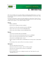
1. INTRODUCTION
This manual is intended for anyone configuring Rabbit’s EM1500, an industrial grade serial-to-Ethernet
converter and modem.
Many of the terms you will find in this manual are defined in C., “Glossary of Terms.” In the electronic
versions of this manual, the first occurrence of the term will have a link to its meaning in the alphabetized
list in the appendix.
1.1 Overview of the EM1500
The primary function of the EM1500 is as a serial to TCP/IP protocol converter, to convert a full duplex
RS-232 or half-duplex RS-485 serial stream to a TCP/IP stream. The serial stream consists of at least the
transmit and receive data, plus optional "modem control" signals.
The EM1500 has 5 serial ports. It has 4 RS232 serial ports, and a half-duplex RS485 port, all of which
may be connected to different remote TCP/IP hosts. That is to say, each serial port may connect over the
Internet, or a local Ethernet LAN, to a single host at any one time; however, the serial ports can all be connected to different hosts at the same time. The remote host may also be another EM1500.
In addition to the serial streams, which are transferred via TCP (Transmission Control Protocol) sockets,
there is also a control socket which can be used to configure and monitor the EM1500 as a whole. The
control socket uses UDP (User Datagram Protocol) rather than TCP.
After the EM1500 has been configured locally (i.e., on the same LAN as the host PC running the configuration software) the configuration socket allows the EM1500 to be remotely configured over the Internet.
To make remote configuration secure, you can choose to encrypt configuration data. (See “Secure config”
on page 35 for instructions on how to do this.) This protects the EM1500 from accidental or malicious
tampering. The serial data streams are not protected in the current firmware release.
Success in today’s marketplace demands rapid, low-cost access to information. The EM1500 was designed
to:
• easily interface legacy RS-232 devices to Ethernet, allowing communication to remotely located
devices or computers.
• extend the communication distance between two RS-232 devices, i.e., act as a transparent serial
bridge.
• allow easy setup and monitoring
EM1500 User’s Manual
www.rabbit.com
1
1.2 Summary of Features
Physically and functionally the EM1500 is a black box. As any good black box should be, the EM1500 is
simple to use. No programming is needed. The tight integration of hardware and software offers unparalleled reliability. Quick configuration over Ethernet, using a web browser or the stand-alone configuration
program, is easy and convenient.
The performance of the EM1500 is:
• Net long term throughput of 460800 bps full-duplex (FDX), assuming Ethernet/Internet link is not
the bottleneck.
• Short term burst rates up to 1Mbit/sec net.
• Any one port may achieve up to 230400 bps FDX.
The EM1500 interfaces with all types of serial devices: modems, sensors, card readers, bar scanners, printers, etc.
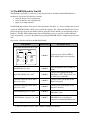
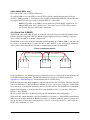
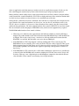
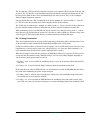
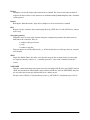
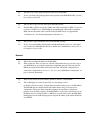
Figure 1.1 Block Diagram of EM1500 Application
Serial
Device
Serial
Device
Internet
RS-485
device 0
EM1500
...
Serial
Device
Serial
Device
RS-485
device 30
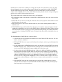
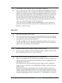
Having two EM1500s allows you to create a transparent serial bridge, thereby use some of the more
advanced software features, such as packetization and protocol conversions. For more information on
these features, see .
Figure 1.2 Transparent Serial Bridge
Serial
Device
2
EM1500
EM1500
Internet
www.rabbit.com
EM1500
Serial
Device
Introduction
1.2.1 Hardware Highlights
• Low-EMI Rabbit 3000 microprocessor, running at 44.2 MHz
• 10/100Base-T Ethernet, RJ-45
• 9-wire DTE, RS-232 (also known as SER1)
• 9-wire DCE, RS-232 (aka SER2)
• Configurable RS-232 serial port on 10-pin header (aka SER3):
3- and 5-wire options, or 9-wire DTE at TTL levels
• 3-wire RS-232 serial port on 10-pin header (aka SER4)
• RS-485, half duplex (aka RS485)
• 5 digital I/0s on 10-pin header (PF0-4)
• 2 digital open collector outputs (OUT0 and OUT1) on 9-pin header
• 3 digital inputs (IN0-2) on 9-pin header, suitable for interfacing to mechanical switches or logic
level circuits
• SPDT relay contacts, allows EM1500 to cycle power to attached device, or to switch other signals
• 4 status LEDs
Power, Link, Active and User
• One-shot reset button
• Wide input power capability (9-36 VDC)
EM1500 User’s Manual
www.rabbit.com
3
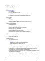
1.2.2 Software Highlights
• Serial-to-Ethernet protocol converter
• on all serial ports
• Serial port geometry:
• 75 to 230400 bps
• none, even, odd, mark, space parity
• 7 or 8 data bits
• 1 stop bit only, or 2 stop bits may be emulated using “mark” parity.
• Flow control:
• None
• XON/XOFF
• Hardware: CTS/RTS, DTR/DSR if these signals available to the port.
• RS232/485 serial protocols:
• standard asynchronous
• async with timing-based packetization
• async with CRLF (or other fixed string) packetization
• 9th bit low protocol for start-of-frame
• Automatic polling of serial device is possible
• All serial ports may emulate AT (Hayes-compatible) command set.
• RS485 transmit enable discipline:
• transmit whenever data present
• transmit only after idle time
• Internet protocols:
• "raw" data stream over TCP
• RFC2217 protocol:
EM1500 acts as "modem server" or "serial port server"
Works with popular PC COM port redirector
• RFC2217 + Rabbit extensions for packetized data and for two EM1500s communicating with
each other. Extensions are transparently negotiated.
• EM1500 can be 'server' and/or 'client' (server only for RFC2217 protocol)
• Connections can be actively opened (client mode) based on modem line conditions, on
received characters, on ATD type commands, or unconditionally.
• Connections can be passively opened (server mode) based on modem line conditions, on ATA
type commands, or unconditionally.
• Connections may be closed based on modem line conditions, +++ATH type commands, network timeouts or automatic serial device polling timeouts.
4
www.rabbit.com
Introduction
• Ethernet network interface:
• IP address assignment via DHCP, directed ping, or statically assigned.
• Supports DNS (name server) queries
• Configuration:
• via web browser.
• via standalone configuration program running on:
• Win95/98/2000/XP/NT
• 80x86-based Linux
• based on open source GUI toolkit (FOX).
• relatively easy for OEMs to customize
• EM1500 may be configured to require encrypted configuration updates. These are supported by the stand-alone program. Subject to U.S. export restrictions.
• EM1500s can be automatically “discovered” on the local Ethernet segment.
• display dynamic unit status in near real-time.
• EM1500s can be partially reconfigured during operation without manual intervention using
RFC2217, e.g., change serial port speed.
• Auxiliary I/Os:
• May be configured for initial state and direction.
• Manual override using status window of stand-alone configuration program (GUI) or web
browser.
• Relay
• May be configured to change state when a TCP connection is established to any serial port.
• Manual override from GUI or web browser.
• Operating modes:
• Normal run mode on power-up if unit is already configured.
• Other operating modes are determined by how long reset switch is held down:
• Normal run (0-4 sec)
• Run in local configuration mode only (4-10 sec)
• Reset to factory defaults and run in local configuration mode (over 10 sec).
EM1500 User’s Manual
www.rabbit.com
5
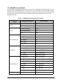
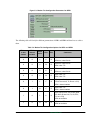
1.2.3 EM1500 Factory Defaults
Every EM1500 is shipped with default values for some of the configuration parameters already set. Some
parameters have been left blank where it makes no sense to have a default, such as the IP address and netmask for the unit. The following table gives all of the factory defaults. To reset your unit to these defaults,
press down the reset switch for 10 seconds. Parameters that have been left blank or are zero, are not
included in this table.
Table 1-3. EM1500 Default Configuration Parameters
Configuration
Category
Configuration Parameter
Default Setting
Unit Name
EM1500-fac-dflt
TCP Keepalives
7200
Direction/State PF0-4
In/Low
State OUT0 and OUT1
Hi-Z
Relay
Open
Enable Connections
ON
Use DHCP
ON
Ping configure
ON
Enable config
ON
Enable discovery
ON
Speed
115200 (SER4) 19200 (all others)
Geometry
8N1 (all serial ports)
Flow control (Tx and Rx)
None (all serial ports)
Relay action
None (all serial ports)
Relay timer (ms)
10000 (all serial ports)
AT command set
OFF (all serial ports)
DSR/DTR control
Active (all serial ports, except RS485)
CTS/RTS control
Active (all serial ports, except RS485)
DCD control
Active (SER2 only)
RI control
OFF (SER2 only)
Use PF0-3
OFF (SER3 only)
RS232 levels
OFF (SER3 only)
Enable poll
OFF (all serial ports)
General
Aux I/O
Network (Ethernet)
Serial (Basic)
Modem Emulation
Polling
6
www.rabbit.com
Introduction
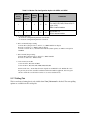
Table 1-3. EM1500 Default Configuration Parameters
Configuration
Category
Opening
Closing
Protocol
EM1500 User’s Manual
Configuration Parameter
Default Setting
Local TCP port
SER1-8888, SER2-8889, SER3-8890
SER4-8891, RS485-8892
Remote TCP port
same as local TCP port
Ephemeral port
ON (all serial ports)
Use Nagle
ON (all serial ports)
Don’t Purge
OFF (all serial ports)
Incoming connection
Always (all serial ports)
Active Open: Always
OFF (all serial ports)
Active Open: When DSR/DTR
OFF (all serial ports)
Active Open: When DCD
OFF (all serial ports)
Active Open: When RI
OFF (all serial ports)
Active Open: Any char
OFF (all serial ports)
Active Open: Specific char
OFF (all serial ports)
Active Open: Char to open
13 (all serial ports)
DSR/DTR dropped
OFF (all serial ports)
Modem control, not close on
DSR/DTR drop
OFF (all serial ports)
DCD dropped
OFF (all serial ports)
Network timeout
OFF (all serial ports)
Modem Server
ON (all serial ports)
Rabbit Extensions
ON (all serial ports)
Packetizing
None (all serial ports)
www.rabbit.com
7
1.4 The EM1500 and its Tool Kit
The EM1500 is packaged in a small, heavy duty metal enclosure. Included with the EM1500 unit is a
small plastic bag labeled 151-0124 that contains:
• One 9 pin positive latch crimp housing
• One 3 pin positive latch crimp housing
• 20 pieces of crimp terminals
The EM1500 ships without cables, power or documentation. All cables, etc., for use with the unit are packaged in the EM1500 Tool Kit, which may be purchased separately. The cables in the Tool Kit may also be
puchased separately using the part numbers shown in the table below. Initially you will probably want to
purchase a Tool Kit. With subsequent purchases of EM1500s you may or may not want the additional
cables and manuals, so you have the option of just getting the EM1500 with the crimp housings and terminals.
Here are the cables that will be in the EM1500 Tool Kit:
Tool Kit Item
Rabbit Part #
Description of Use
DE9F-DE9F null-modem 10 ft. cable
DE9, F
Rx
Tx
DTR
GND
DCD,DSR
RTS
CTS
RI
DE9,F
2
3
4
5
6,1
7
8
9
3
2
1,6
5
4
8
7
9
Tx
Rx
DCD,DSR
GND
DTR
CTS
RTS
RI
540-0063
Serial crossover cable for SER1 if
DCD and RI signals are not required.
DE9M-DE9F 10 ft. cable
540-0052
Serial straight-thru cable for SER1 or
SER2.
10-pin IDC-DE9M 12 in. cable1
540-0047
Connects the 10-pin header on the
EM1500 to a DCE. This is for the case
of SER3 being a full DTE.
3-pin latch connector with 22 AWG
wires 12 in. cable1
540-0073
Connects to the 3-pin header for the
RS-485 serial port.
9-pin latch connector with 22 AWG
wires 12 in. cable1
540-0074
Connects to the 9-pin header for the
digital I/O and relay
CAT5E Ethernet patch 7 ft. cable
540-0076
Connects the Ethernet connector on the
EM1500 to a hub.
CAT5E Ethernet cross-over 7 ft. cable
540-0077
Connects the Ethernet connector on the
EM1500 directly to the Ethernet
connector of another EM1500 or a PC.
Programming cable
101-0542
For downloading firmware upgrades.
1. Part # 151-0115 is a bag of 3 cables: 540-0047, 540-0073 and 540-0074.
8
www.rabbit.com
Introduction
The other EM1500 Tool Kit items are:
• 24V power supply (Tool kits sold outside North America do not include a power supply. The power
•
•
•
•
requirements are 9 V to 36 V DC, 1.5 W typical.)
Wire kit 22 AWG (Rabbit Part # 805-0038)
Rabbit Engineering Demo Board
EM1500 User’s Manual
CD containing the Window and Linux versions of the stand-alone configuration program, a binary
version of the EM1500 firmware, and the RFU (and support files: flash.ini,
coldload.bin, pilot.bin) to download the firmware.
• Rabbit screw driver
1.4.1 Rabbit Engineering Demo Board
The demo board is useful for testing the functionality of the relay and digital I/O on the 9-pin connector.
Look in Section 2.3 for some tips on how to use it.
1.5 Contact Information
If you purchased your EM1500 through a distributor or Rabbit Semiconductor partner, contact the distributor or Rabbit partner first for technical support.
To contact Rabbit Semiconductor:
• Check the Rabbit Technical Bulletin Board at www.rabbit.com/support/bb/.
• Use the Technical Support e-mail form at www.rabbit.com/support/questionSubmit.shtml.
EM1500 User’s Manual
www.rabbit.com
9
10
www.rabbit.com
Introduction
2. GETTING STARTED
This chapter describes the hardware connections necessary for configuring the EM1500. This is followed
by an example of telneting to a unit and a quick introduction to the Rabbit Engineering Demo Board.
2.1 Hardware Connections
An Ethernet connection is required for configuration. You may use a browser or the stand-alone configuration program that is included on the CD in the EM1500 Tool Kit.
2.1.1 Ethernet Connection
To make the Ethernet connection, you will need:
• host PC with Ethernet access (i.e., RJ-45 jack)
• Ethernet cross-over cable, or a hub1 and 2 straight-through cables2
• power supply2
2.1.1.1 Host PC with Ethernet Access
Your PC must have an RJ-45 jack to connect to an Ethernet network. It is an 8-wire connector that looks
similar to the ubiquitous (and slimmer) 6-wire RJ-11 connector used for telephone equipment. If your PC
does not have an RJ-45 jack, you will need to install a 10Base-T or 100Base-T Ethernet card.
Please note that neither the telnet example described in this chapter, nor the configuration process
described later in the manual have need of the EM1500 explicitly knowing the IP address of the host PC.
This is because the EM1500 will not be initiating the Ethernet connection in these 2 cases. This is not to
say that the host PC does not need an IP address—it definitely does. How this is accomplished depends on
the operating system and the network card that is installed on the machine.
2.1.1.2 Using a Cross-Over Cable
An Ethernet cross-over cable can connect the RJ-45 jack on the front panel of the EM1500 directly to the
RJ-45 jack of the host PC. This creates a very small isolated LAN on your desktop.
If you are using this hardware configuration, an IP address will have to be statically assigned to the
EM1500 since it is unlikely there will be DHCP services available.
1. A hub may be purchased in the TCP/IP Tool Kit, which is sold separately.
2. A suitable power supply and the cables needed by the EM1500 for Ethernet connection are supplied in
the EM1500 Tool Kit, which is sold separately. Tool kits sold outside North America do not include a
power supply.
EM1500 User’s Manual
www.rabbit.com
11
2.1.1.3 Using a Hub and Two Straight-Through Cables
The Ethernet connection does not have to be direct. The EM1500 and the host PC may be connected to the
same LAN through a hub. This way has the benefit of allowing more than one EM1500 unit to be configured in the same configuration session.
Of course, the hub can also be connected to a larger LAN, e.g., your company network or a test network.
Always check with your network administrator before physically connecting to an existing network.
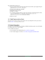
2.1.2 Power Supply
To supply power to the EM1500 use the specified AC adapter1.
Connect the bare wires from the AC adapter to the V_INPUT
(“+”) and GND (“-”) terminals of the screw terminal connector.2 The wire with the red sleeve should be connected to the
GND
“+” terminal (left side of screw terminal), the black wire to the
V_INPUT
“-” terminal (right side of screw terminal). If the wires on your
power supply do not have the red and black sleeves, you may
determine which wire is which by looking on the label of the
adapter. Plug in the adapter and verify that the LED labeled PWR comes on steady.
2.1.3 Serial Port Connection
After making the Ethernet hardware connections and supplying power to the EM1500, the unit is ready for
complete configuration. Before delving into all the configuration parameters, we will step through a simple example that will require minimal configuration. A serial port connection is not required to configure
the unit, but is required for this example.
You must have a free COM port on an available PC. This can be the same PC that has the Ethernet access.
The following directions assume there is only one host PC, and that it has both serial and Ethernet access
to the EM1500.
Connect the COM port of the PC to SER2 on the EM1500 using a serial straight-through cable. The connector for SER2 is located on the upper right side of the back panel of the EM1500.
1. The adapter specification is 9 V to 36 V DC, with 1.5 W typical.
2. The screw terminal connector snaps into place and is easily removed from the EM1500 for ease of use.
12
www.rabbit.com
Getting Started
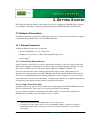
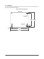
2.2 Up and Running
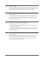
A simple block diagram of the example is shown below.
Figure 2.1 Host PC connected to an EM1500
Hub
Ethernet
Ethernet
EM1500
EM1500
SER2
SER2
Serial Cable
Serial Cable
Direct connection using
an Ethernet cross-over cable
Connection using a hub and
Ethernet straight-through cables
(as described in Section 2.1.1.1)
(as described in Section 2.1.1.2)
There are two software programs that run on the host PC for this example:
• a terminal emulator
• emconf.exe (Windows) or emconf (Linux), the stand-alone configuration program located on the
CD in the EM1500 Tool Kit.
If there is a DHCP server on the same LAN as the host PC, you will not need to make any configuration
changes on the EM1500. Otherwise, you will need to statically assign an IP address to the EM1500. Please
see Chapter 3, “Assigning an IP Address to the EM1500,” for directions on how to accomplish this.
2.2.1 Serial Port Configuration
Open any terminal emulator program. In this example, we will use Tera Term. Choose a serial connection,
then select the COM port that is connected to the EM1500. Go to the Setup menu and select “Serial port
...” to bring up the “Serial port setup” dialog. The serial port geometry (e.g., 8N1: character size is 8 bits,
there is no parity and there is one stop bit.) and speed are set in this dialog. If you are using some other terminal emulator, the process might be slightly different, but each one has a dialog box that lets you set
serial port parameters. The defaults in Tera Term are probably 8N1, no flow control and the baud rate is
9600 bps. Change the baud rate to 19200 bps and click on OK.
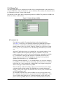
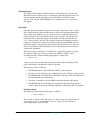
Open emconf or emconf.exe. This program will try and discover any EM1500s that reside on the
same LAN as the host PC. You should be able to see the EM1500 on the upper left side of the program
window. Click on its icon; this highlights the entry and shows status information for the unit in the area
below its selection. The entry includes the IP address if DHCP was successful.
EM1500 User’s Manual
www.rabbit.com
13
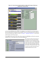
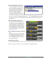
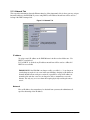
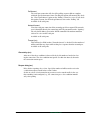
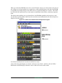
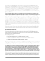
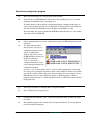
Figure 2.2 Screen Capture of the Stand-Alone Configuration Program, Showing an
EM1500 with Factory Defaults
A factory-default EM1500 will have SER2 set to 19200 bps for speed and 8N1 for serial port geometry.
The screen shot shows the Serial tab selected for SER2. You may access this information by clicking on
the Serial tab and then on the SER2 tab. (Please see Chapter 5. “EM1500 Configuration,” for more information about the stand-alone program.)
If using DHCP did not result in an IP address being assigned to the EM1500, you will need to assign one
manually. First, get an IP address from your network administrator.
Now, click on the Network tab and type in
the IP address in the first field of the Network dialog. Save the configuration change
by pressing <Ctrl+S> (or by clicking on File
| Save). You will see the entry for your unit
updated in the upper left portion of the program window to include the IP address. This
is the value you will use in the telnet command described in the next section.
14
www.rabbit.com
Getting Started
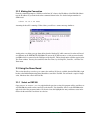
2.2.2 Making the Connection
From the command prompt or a DOS box on the host PC, telnet to the IP address of the EM1500. Substitute the IP address of your unit in the telnet command shown below. Use the default port number for
SER2: 8889.
telnet 10.10.6.44 8889
Assuming the host PC is running a Telnet client, you will see a connect message similar to:
At this point, everything you type from the keyboard of the host PC while connected via telnet will travel
over Ethernet to the EM1500. The EM1500 will convert the TCP/IP stream to a serial stream and send it
out SER2 which is connected to the COM port of the host PC. The keyboard entries will then appear in the
Tera Term window. You may also send files from Tera Term, by selecting File | Send file... from the Tera
Term menu.
2.3 Using the Demo Board
This section describes several ways to connect the auxiliary I/O that is available from the EM1500’s 9-pin
header to the Rabbit Engineering Demo Board that came in the Tool Kit. You will need a couple of single
wires, like those that came in the Tool Kit.
2.3.1 Select an EM1500
Open emconf or emconf.exe. As explained in the previous section, this program will try and discover
any EM1500s that reside on the same LAN as the host PC. You should be able to see the EM1500 on the
upper left side of the program window. Click on its icon; this highlights the entry and shows status information for the unit in the area below its selection.
EM1500 User’s Manual
www.rabbit.com
15
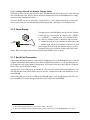
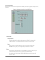
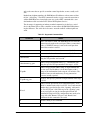
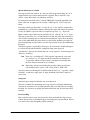
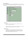
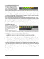
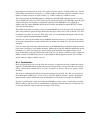
In the status/debug area of the program window, there is a grouping of controls for the auxiliary I/O that
looks like this:
Figure 2.3 AUX Tray
Detailed information about the status/debug area of the configuration program is in Section 5.1.11.
2.3.2 Wiring the Demo Board to the Selected EM1500
You must follow these steps before you can use the Demo Board to test the relay and digital I/O:
1. Use a single wire to connect +K from the Demo Board to Vinput (screw terminal) on the EM1500.
2. Use a single wire to connect GND from the Demo Board to GND (screw terminal) on the EM1500.
3. Connect the 9-wire assembly with plug that came with the Tool Kit to the 9-pin connector on the
EM1500. The3 pins for the relay, plus the 2 digital outputs and 3 digital inputs are all available here.
2.3.3 Digital Output
To test the digital output, wire OUT0 and OUT1 to any LED on the Demo Board. To locate the wires coming from OUT0 and OUT1, do one of 2 things: look at the unit itself, then read the text on the back panel
labelling the pins on the 9-pin connector; or look at the pinout diagram by selecting the “Pinouts” tab, then
the “9-pin” tab in the stand-alone program.
Now you can click on OUT0 or OUT1 in the AUX tray to see the LED on the Demo Board to which it is
connected, light up.
16
www.rabbit.com
Getting Started
2.3.4 Digital Input and Relay
To test the relay and the digital input, follow these steps:
1. Move the jumper at H2 on the Demo Board to position 3-5 and 4-6.
2. Using the 9-wire assembly, wire IN0 to Relay NC.
3. Using the 9-wire assembly, wire IN1 to Relay NO.
4. Connect Relay Common from the 9-wire assembly to SW1 on the Demo Board.
5. Toggle the relay button in the AUX tray. When the relay is on the button is orange, when off, the
color changes to gray.
Press down SW1 on the Demo Board. Depending on the state of the relay you will see either IN0 or IN1
change from bright green to dark green in the AUX tray.
• When the relay is open, contact is made with the normally closed pole; therefore, pressing SW1(i.e.,
completing the circuit) causes the state of IN0 to change, which is then reflected in the button color
for IN0.
• When the relay is closed, contact is made with the normally open pole; therefore, pressing SW1(i.e.,
completing the circuit) causes the state of IN1 to change, which is then reflected in the button color
for IN1.
EM1500 User’s Manual
www.rabbit.com
17
18
www.rabbit.com
Getting Started
3. ASSIGNING AN IP ADDRESS TO THE
EM1500
To talk to the EM1500 over its Ethernet interface requires an IP address.
3.1 How to Obtain an IP Address
There are two ways to obtain a valid IP address for the EM1500. One is through dynamic assignment using
DHCP/BOOTP. The EM1500 is a DHCP client by default. If a DHCP server resides on the same LAN as
the EM1500, an IP address will be assigned to the EM1500 when it is powered on.
Dynamic allocation of an IP address works well during configuration, but if the EM1500 will act as a
server when it is deployed in the field you will need to have a permanent IP address assigned to it so that it
can be contacted later.
The second way to obtain a valid IP address is to have your network administrator assign one to you.
Assigning an IP address to the EM1500 is explained in the next section.
3.2 How to Tell the EM1500 its IP Address
There are two ways you can tell the EM1500 its statically assigned IP address.
• Directed ping
• Stand-alone configuration program
The latter you might recognize as a way to configure the EM1500. The first method, directed ping, is only
useful for assigning the IP address.
After using directed ping to set the IP address, you can then use a web browser to complete the configuration process.
EM1500 User’s Manual
www.rabbit.com
19
3.2.1 Directed Ping
To use this method you must already have an IP address and the MAC address of the EM1500. The IP
address has presumably been assigned by your network administrator.
The MAC address is assigned at the factory. The first six digits are 00:90:C2. The first six digits are the
same for every network device manufactured by Rabbit. The last six digits of the EM1500’s MAC address
are printed on a label affixed to the front panel of the unit. The six digits are identified by “MAC ID:”
The EM1500 must be on the same LAN as the host machine from which you issue the following ARP and
ping commands. From a DOS box or command prompt, type:
arp -s xxx.xxx.xxx.xxx yy-yy-yy-yy-yy-yy
substituting your IP address for the xx.xx... and your MAC address for yy-yy... This sets up the next command, which is:
ping xxx.xxx.xxx.xxx
This is the command that actually assigns the given IP address to the unit. Directed ping may only be used
once, or not at all if the IP address was set through the stand-alone configuration program.
3.2.2 Stand-Alone Configuration Program
The stand-alone program comes in two versions, one for x86-based Linux (emconf) and one for Windows (emconf.exe). You will find the stand-alone program on the CD that comes with the EM1500
Tool Kit. Unlike directed ping, this method does not require you to know an IP and MAC address.
The stand-alone program allows multiple units to be configured at the same time. All EM1500s that are on
the same LAN as the host running the stand-alone program (and have not been “secured” by another host)
will respond to the special broadcast packet that is sent out. The MAC address will be displayed for every
unit that is discovered. See Figure 5.1 for an illustration of what this looks like onscreen. The figure shows
that one EM1500 was discovered.
By default, the EM1500 is a DHCP client. This means that it will accept a dynamically assigned IP address
if one is available. You may assign a static IP address by going to the Network tab of the stand-alone program and entering it into the IP address field. If the unit will be deployed in an environment that has a
DHCP server, be sure to uncheck Use DHCP in the Network dialog unless you want the static IP address
to be a fallback for DHCP. Save the changes by pressing <Ctrl+S> or by selecting Save changes from
the Edit menu.
The EM1500 needs to know more than its IP address. The rest of the configuration parameters may be set
using the stand-alone configuration program, emconf. Each parameter will be explained fully in the next
chapter.
20
www.rabbit.com
Assigning an IP Address to the EM1500
4. EM1500 SPECIFICS
This chapter describes the front and back panels of the EM1500 and in particular the pin-outs for the serial
ports and the jumpers for changing their default behavior.
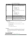
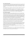
4.1 Front Panel of EM1500
On the front panel are connectors for Ethernet, RS-485 and power. There is also a reset button, LEDs, and
a label containing the last six digits of the unit’s MAC address. The first six digits of the MAC address are:
00:90:C2. This information will be important later if you are configuring multiple units at a time or you
use directed ping to assign an IP address.
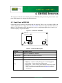
Figure 4.1 Front Panel of EM1500
MAC ID:
ETHERNET
Â
RJ-45
ACT
USER
RESET
+
+ GND -
1x3 IDC
header
-
LINK
PWR
POWER
RS-485
9-36 VDC
.
Table 4.1 Front Panel Description
Connector
Description of Use
RJ-45
Connects to 10/100Base-T Ethernet
1x3 IDC header
Connects to RS485 half duplex serial port
Screw terminal
Connects to 9-36V DC power adapter; snaps in and out for ease of use.
LEDs
There are 4 LEDs:
• PWR (red) - comes on steady when power successfully applied.
• ACT (yellow) - flashes when data traffic present.
• LINK (green) - comes on steady when Ethernet connection is made.
• USER (red and green, orange if both red and green on at the same
time) - shows overall status/run mode. See Table 4.2 for more
information.
EM1500 User’s Manual
www.rabbit.com
21
Table 4.1 Front Panel Description
Connector
Description of Use
Reset button
The unit is reset whenever the reset button is pressed. The operating mode
is usually determined by how long the reset button is held down:
• 0 to 4 sec - Normal run
• 4 to 10 sec - Run in local configuration mode
• over 10 sec - Reset to factory defaults, run in local config mode.
4.1.1 User LED Patterns
The User LED on the front panel is a bi-color LED. It has a red and a green chip within, which provides a
total of four states: off, red, green and orange. It indicates the overall status of the EM1500 as follows:
Table 4.2 User LED Patterns
LED pattern
Status of EM1500
OFF
Initializing after power-up or reset.
Solid Red
Run mode, with a valid IP address assigned to the Ethernet
interface.
Run mode, but no IP address has been obtained. This means
Orange with brief off-period the unit has not been configured, or it has been configured to
use DHCP but no DHCP server is available, and no fallback
every second
IP address was identified.
Flashing green 4 times per
second
Reset has occurred, reset button has been pressed down for
more than 4 seconds but less than 10 seconds.
After the reset button is held down for 10 seconds total time,
the LEDs will go OFF and the unit will be reset to factory
default configuration.
Alternating green and
orange, 2 times per second
Factory default configuration mode. After configuring the
unit for the first time, you may reset the unit by pressing the
reset button to make the LEDs indicate normal run mode,
i.e., solid red.
Alternating red and green
every second
Special self-test mode. This mode is only used by the
factory, so you should not normally observe this mode.
Any other pattern (usually
Self-test or other internal error. If you see this mode, contact
green flash followed by one
technical support.
or more red flashes)
You may increase the functionality of the User LED to include the status of the Tx and Rx lines for one or
more of the serial ports. Please see “LED shows Tx/Rx state in run mode” on page 39 for instructions on
how to do this.
22
www.rabbit.com
EM1500 Specifics
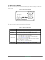
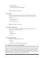
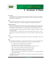
4.2 Back Panel of EM1500
The connectors on the back panel are shown in the following figure. Please note that pin 1 is PF2 on the
2x5 IDC header.
Figure 4.2 Back Panel of EM1500
SER 2 / RS-232
DE9 F
RLY
OUT
IN
1x9 IDC header
DE9 M
COM
NO
NC
OUT1
OUT0
GND
IN2
IN1
IN0
Rx3
Tx4
PF1
PF3
Rx4
2x5 IDC
header
PF4
SER 1 / RS-232
PF2
PF0
Tx3
GND
SER 3 / SER 4
The connectors on the back panel are described in the following table.
Table 4.3 Back Panel Description
Connector
Description of Use
DE9, male
For connection to RS-232 serial port (SER1) wired as a DTE.
DE9, female
For connection to RS-232 serial port (SER2) wired as a DCE.
2x5 IDC header
For connection to configurable serial port (SER3):
• 3-wire, pins 3 (Rx), 5 (Tx), and 9 (GND)
• 5-wire, pins 3 (Rx), 5 (Tx), 4 (RTS), 6 (CTS) and 9 (GND)
• 9-wire, see Figure 4.5 for pins used.
For connection to 3-wire serial port (SER4). This is only available if
SER3 is configured as a 3-wire port.
• 3-wire, pins 4 (Tx), 6 (Rx) and 9 (GND).
1x9 IDC header
Digital I/O, GND, and the SPDT relay come out on this header.
EM1500 User’s Manual
www.rabbit.com
23
4.3 Connector Pin-Outs
This section describes the pin-outs for the serial ports and the 9- and 10-pin connectors.
4.3.1 Serial Port 1 (SER1)
The serial port known as SER1 is wired as a DTE with a DE9 male connector. It is located at the lower
right on the rear of the unit. The figure below shows the pin-out. The black circles (Tx, DTR and RTS)
denote outputs. The white circles denote inputs.
Figure 4.3 Pin-Out for SER1
Tx
Rx
DCD
DTR
5
1
DSR
6
RI
9
RTS
GND
CTS
4.3.2 Serial Port 2 (SER2)
The serial port known as SER2 is wired as a DCE with a DE9 female connector. It is located at the upper
right on the rear of the unit. The figure below shows the pin-out. The black circles denote outputs. The
white circles denote inputs.
Figure 4.4 Pin-Out for SER2
DTR
GND
Tx
Rx
5
1
RI
9
6
CTS
24
DCD
DSR
RTS
www.rabbit.com
EM1500 Specifics
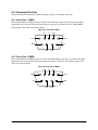
4.3.3 Serial Port 3 and 4 (SER3 & SER4)
Serial ports SER3 and SER4 are available on the 2x5 IDC header (aka, the 10-pin header) on the back
panel of the EM1500. By default, they are both 3-wire ports at RS-232 levels. Both can be jumpered for
TTL level signals. SER3 is also configurable as a 5-wire RS-232 or TTL level port or a 9-wire port at TTL
levels. Both the 5- and 9-wire options for SER3 preclude the use of SER4 since its Tx and Rx pins will be
used as modem control lines for SER3.
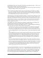
Figure 4.5 10-Pin Header Signal Names
GND
PF0 / DTR
Tx3
Rx3
9
PF2 / DCD
1
10
2
PF4
PF3 / RI Rx4 / CTS Tx4 / RTS
PF1 / DSR
NOTE: If SER3 is used in 3- or 5-wire mode, PF0-3 may be used as auxiliary TTL I/Os. PF4
is always a TTL I/O.
NOTE: Pinout allows ribbon cable crimped to 10-pin plug on one end and DE9 male
crimped to the other end to have signals routed in the standard manner.
3-Wire Option (SER3 and SER4)
The 3-wire option is available with either RS-232 or TTL level signals.
1
2
3
4
5
6
JP2
Fresh from the factory SER3 and SER4 are configured as 3-wire RS-232 serial port, available on pins 3 (Rx) and 5 (Tx). JP2 is jumpered on 1,3 and 2,4: meaning RS-232 signal
levels for SER3. To change to TTL levels move the 2 jumpers down one position on JP2 to
3,5 and 4,6. For instructions on moving jumpers, please see Section A.4.
Pins 3 and 5 are either RS-232 or TTL, depending on the jumper at JP2. Pins 4 and 6 are
either RS-232 or TTL, depending on the jumper at JP3 (see 5-wire option).
5-Wire Option (SER3 only)
The 5-wire option is available with either RS-232 or TTL level signals.
1
2
3
4
5
6
7
8
9
10
JP3
To operate SER3 as a 5-wire port, you configure it to use hardware flow control (see
Section 5.1.4). Pins 4 (RTS) and 6 (CTS) are used on the 10-pin header. The signal levels
of pins 4 and 6 depend on the JP3 setting. The picture of JP3 shown here is of the jumpers
at 1,3 and 2,4—the default setting—which specifies RS-232 level signals on RTS and
CTS. Changing the jumpers to positions 3,5 and 4,6 cause the flow control lines for SER3
to be TTL levels.
EM1500 User’s Manual
www.rabbit.com
25
9-Wire Option (SER3 only)
The 9-wire option is only available at TTL levels.
To configure SER3 as a 9-wire DTE go to the AUX I/O tab in the configuration program. Check the
checkbox, “SER3 uses PF0-3.” (This option is also available on the Modem/SER3 tab.) JP2 and JP3 must
be jumpered for TTL levels if you want to configure SER3 as a 9-wire DTE.
NOTE: It is possible to use SER3 in 9-wire mode with “pseudo-RS232” signal levels. See
Modem/SER3 panel, check “RS232 levels.” Drive levels are 0-3 V TTL, which is below
specification, but may work for short connections.
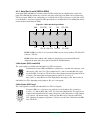
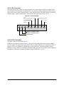
4.3.4 Serial Port 5 (RS485)
The EM1500 comes with an RS-485 port. Its connector is located on the front of the unit underneath the
Ethernet connector. Compared to RS-232, RS-485 supports higher speeds (up to 250 kbps), longer distances, and may be used in a multidrop configuration.
The EM1500 can be used in an RS-485 multidrop network spanning up to 1200 m (4000 ft), and there can
be as many as 32 attached devices. Connect the 485+ to 485+ and 485– to 485– using single twisted-pair
wires as shown in the figure below. Note that a common signal ground is recommended.
485-
GND
485+
485-
GND
485+
485-
GND
485+
Figure 4.6 Multidrop Network
For best performance in a multidrop network, termination resistors are enabled only on the end nodes and
are disabled on intervening nodes. The EM1500 termination resistors are enabled by default. See
Appendix A.4, “EM1500 Jumpers,” for information on how to disable them.
The RS485 port has some unique properties compared with the other four serial ports. The main difference
is that it is half duplex i.e. only one direction, transmit or receive, can be active at one time. Another difference is that there are no modem control lines such as CTS, RTS or DCD. The last difference is that RS485
supports multi-dropping i.e. more than one device using the RS485 cable as a “party line.” This is also
known as “daisy chaining.”
Because of these differences, the RS485 port has special considerations when configuring it.
The normal flow control disciplines associated with RS232 serial ports (i.e., XON/XOFF or modem handshake lines) do not apply. Instead, the RS485 port requires a transmitter enable discipline. In general, there
must be one device or node that is configured to be a “master,” with every other device connected to the
RS485 cable configured as a “slave.”
26
www.rabbit.com
EM1500 Specifics
Usually, the master has ultimate control of who speaks, and when. The master can transmit whenever it
knows that a slave is not currently transmitting. A slave can only transmit when the master has given it
express permission to do so.
The EM1500 should be used as the master. All other nodes should be configured as slaves in the sense that
they only transmit when specifically addressed by the EM1500 that is acting as master.
Messages are generally limited to a fixed maximum size. The nature of the medium does not lend itself to
long “monologues” from any one device, including the master. Typically, the master will issue a short
command packet, which is addressed to a particular slave. The slave will then respond within a fairly
tightly defined interval.
The EM1500 provides some software support for typical RS485 protocols, where messages are less than
an upper limit of 1020 bytes, and the EM1500 is the master device. Since there are many different RS485
protocols, many of which are proprietary, the EM1500 only provides the most general support. Successful
implementation of a particular protocol will require the correct configuration of several other items. The
most important of these are the specification of the transmitter enable discipline (which will usually be
“Rx Idle” in the Serial tab) and the packetizing protocol (in the Protocol tab).
Users of PC COM port redirector software will usually not be able to use the RS485 port successfully.
This is because of limitations in the underlying RFC2217 protocol, which does not have any concept of
packetizing. Full use of the RS485 port requires either another EM1500 or PC software written to take
advantage of the Rabbit extensions to RFC2217. Another EM1500 may be used in client/server mode to
implement a protocol converter. The conversion may be between any of the serial ports, RS232 or RS485,
on the client and the RS485 port of the server (or vice versa).
Implementation of a specific RS485 protocol will generally require in-depth knowledge of the protocol, as
well as thorough understanding of the configuration options outlined in this manual.
Modbus RTU is a widely used protocol, which is a good candidate for use of the RS485 port. We use this
protocol as an example of how to configure the RS485 port for compatibility with an existing, popular protocol.
EM1500 User’s Manual
www.rabbit.com
27
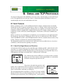
4.3.4.1 Modbus RTU
Modbus RTU (and, incidentally, Modbus ASCII) is a good fit for the half-duplex RS485 port. It has a master and multiple slaves. The master issues a query, then listens for a response from the selected slave.
The RS485 port is set up for 8 data bits with even, odd or mark parity, and one stop bit. A Modbus RTU
message starts with an idle time of at least 3.5 character times, i.e., the RS485 cable must be in steady 'idle'
state for this amount of time. Each packet must be transmitted without any gaps of more than 1.5 character
times.
Following this specification, the Serial tab
for the RS485 port is set to:
Speed: 115200 (this is arbitrary, provided all
devices are set to the same value)
Character size: 8
Parity: Mark (also arbitrary, may be Odd,
Even or Mark for all devices)
Tx Enable: Rx Idle
Rx Idle time: 20 (see below)
Relay action: (as required)
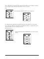
The Protocol tab for the RS485 port is set to:
Modem server: yes (actually, this is a “don't
care”)
Rabbit extensions: yes (required for packetization support)
Packetizing: Idle
Idle time units: byte
Rx idle time: 4 (rounded up from 3.5)
Tx idle time: 4 (rounded up from 3.5)
Max buffer: 1020
Trailing chars: 0
28
www.rabbit.com
EM1500 Specifics
The Modbus RTU timing value is increased to 4, which is the next higher integer above 3.5. There are two
instances where this number is used, both in the Protocol tab:
1. The Rx idle time is used to time the end of an incoming packet. After four character times, the packet is
considered complete, and may be sent to the network.
2. The Tx idle time is the minimum amount of time which the transmitter must be idle before sending a
new packet. As it happens, this value is somewhat superfluous for RS485, since the value mentioned
immediately below will be used instead. (This value is more useful for the RS232 ports, which do not
have transmitter enables, however we specify it here for clarity).
A third timing value, which is longer (and somewhat arbitrary) is set in the Serial tab. This timer is used to
specify the minimum amount of idle time that is required before the master is allowed to enable its transmitter. This is the minimum time; the master will usually not enable its transmitter this quickly because it
will be listening for a response. A value of 20 character times is selected, based on this being sufficient
time for a slave device to formulate and transmit its response. After 20 character times, the master is
allowed to transmit a new packet.
Since the RS485 port can only transmit when its transmitter is enabled, the Protocol:Tx Idle time and
Serial:Rx idle time amount to the same thing (and the maximum of both is used).
From the point of view of one half of the complete connection, i.e. a single EM1500 with an RS485 port
on one side and the network on the other, the following situation obtains:
On the network side, packets are received for later transmission out the RS485 port. On the RS485
side, packets are received for transmission to the network peer. Since packets must be delimited by
strict idle times on the RS485 side, but may arrive from the network in piecemeal fashion, it is necessary for the EM1500 to buffer at least one full packet before it starts getting transmitted out the RS485
port.
When the RS485 port is currently receiving (transmitter disabled), then packets from the network must
be queued. When the RS485 port has been idle (nobody speaking) for 20 character times, the next
packet may be transmitted. Because it is completely buffered, the packet is sent in one continuous
stream without any inter-character gaps. At the end of the packet, the transmitter is disabled and
remains disabled for at least 20 character times. This gives the addressed slave the opportunity to
respond.
If no slave responds within 20 character times, the master is free to send a new packet. If a packet is
already queued, then it will be sent immediately. Otherwise, if only a partial (or no) packet is queued,
then the transmitter will remain disabled until a full packet is available. In the meantime, a slave which
was slow to respond may start transmitting. If the master still has its transmitter disabled, it will start
receiving that packet and be inhibited from enabling its transmitter until the line has been idle for
another 20 character times after the last character received.
It is also possible (and undesirable) for a slow slave to start responding at the same instant that the master
enables its transmitter for a new packet. This causes a "collision" which will usually garble the data. Collisions are not detected by the EM1500 since it does not listen to its own transmissions. The higher level
protocol should include some form of error detection if this is a possibility. For example, Modbus RTU
uses a 16-bit CRC which provides a good probability for the application detecting a garbled packet.
EM1500 User’s Manual
www.rabbit.com
29
4.3.5 9-Pin Connector
The 9-pin connector has various I/O connections plus relay contacts. In0-2 are TTL level inputs which
may be jumpered for all pull-up or all pull-down. Factory default is pull-up. Pull-down requires moving
the zero ohm resistor on JP1. Out0 and Out1 are open collector outputs with diode clamps to ground and
the input supply, capable of sinking up to 750 mA with voltage up to input voltage ± 0.5 V.
Figure 4.7 9-Pin Connector
GND
In2
Out0
In1
Out1
In0
1
9
Relay N.C. (Normally Closed)
Relay N.O. (Normally Open)
Relay common
4.3.6 10-Pin Connector
The 10-pin connector is shown in Figure 4.5.
If SER3 is not configured in software to be a 9-wire port, 4 of the pins on the 10-pin connector (PF0-3)
become available for general purpose I/O; PF4 is always available. PF0-4 may be configured as inputs or
outputs at TTL levels. PF0-4 have 470 ohm series resistor protection , which allows them to tolerate
RS232-level signals. However, the loading of the RS232 input signal may be too high for some equipment.
Internally, the connection is terminated by diode clamps to GND and Vcc (3.3 V).
30
www.rabbit.com
EM1500 Specifics
5. EM1500 CONFIGURATION
This chapter explains all of the available configuration parameters. The stand-alone program (named
emconf for Linux users and emcomf.exe for Windows) will be used for this purpose. Both versions of
the configuration utility are on the CD that comes with the EM1500 Tool Kit.
The information contained in this chapter is also useful for someone using a web browser for configuration
since the user interface for both methods have a similar organization (with some differences) and identical
terminology. If you are using a web browser for configuration instead of the stand-alone program, you will
need to assign an IP address to the unit before you can point your browser at it. For instructions, please see
Chapter 3., “Assigning an IP Address to the EM1500.” This is the main difference between the two configuration methods. The other differences are detailed at the end of the chapter.
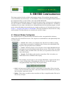
5.1 Ethernet Modem Configurator
The configuration process is broken down into functional areas that correspond with the tab names
arranged vertically in the GUI of emconf. The categories are summarized here and explained fully in the
rest of this chapter.
• General - This is where you set/display router and nameserver addresses and the
security option for encryption of configuration data. You may also enable/disable TCP
keepalives and specify how often to send them.
• Aux I/O - This dialog displays advanced options. Choose View | Advanced from the
main menu if you can not see this tab when you run emconf. This is where you configure SER3 as a full 9-wire DTE. This is also where you set parameters for the relay and
some of the I/O pins.
• Network - The IP address and netmask are entered here. This is also where you
enable/disable the use of DHCP or directed ping.
The remaining categories apply to each serial port individually, as opposed to the unit as
a whole. Clicking on the corresponding tabs will reveal a tab for each serial port
arranged horizontally along the top of the program window.
• Serial - Serial port speed, geometry and flow control settings are entered here. This is also where
you may cause an action on the relay when a connection is made from the network to the serial port
and /or when the connection is closed.
• Modem - This is where you enable software emulation of a Hayes-compatible modem. This may be
done for any serial port.
EM1500 User’s Manual
www.rabbit.com
31
• Polling - This dialog displays advanced options. Choose View | Advanced from the main menu if
you can not see this tab when you run emconf. All polling parameters are set here.
• Opening - The TCP port number for the EM1500’s serial port is set here. Like the IP address for the
unit, a port number must be assigned for any serial port that will be used. If a network connection is
initiated by a serial port, then the remote port and IP address must also be set here. This is also
where you configure the serial port to be a server and/or a client.
• Closing - Closing conditions for the serial port are set here.
• Protocol - This dialog displays advanced options. Choose View | Advanced from the main menu if
you can not see this tab when you run emconf. This is where you may enable the EM1500 to be a
RFC2217 modem server, as well as make it compatible with the use of a PC COM port redirector
that complies with RFC2217. You may also choose to enable extensions to the protocol; the extensions are useful when there are 2 EM1500s hooked up as a transparent serial bridge.
• Pinouts - Here is where you can find pinout diagrams for each of the serial ports and the 9- and 10pin connectors. This is for informational purposes only and does not affect the operation of the
EM1500.
The configuration parameters concerned with basic functionality are found on the tabs named General,
Network, Serial, Opening and Closing. An understanding of the information in the rest of the tabs is
required to have access to the full range of EM1500 features.
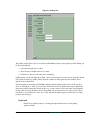
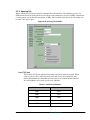
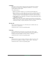
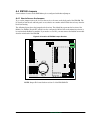
Underneath the titlebar and the menu, the program window is divided into 4 areas.
Figure 5.1 Opening Screen of Stand-Alone Configuration Program
NOTE: You may change the font used in the program by selecting Edit | Fonts from the
menu. The change does not take place until the program is reset.
32
www.rabbit.com
EM1500 Configuration
Area #1. Select EM1500 for Configuration
The listbox in the upper left corner is where
you select EM1500s or configuration databases for viewing and manipulation. File
editing operations may be performed on
any selected entry. For example, double
click on the configuration database
default.emc, then single click one of
its configurations. Now press <Ctrl+C> to
copy the selected configuration to the clipboard; select an EM1500 entry (another single click) and
press <Ctrl+V> to paste the configuration from default.emc to the EM1500. Other file operations
(i.e., Open, Save, Close, etc.) may be performed on the configuration database entries, but not the
EM1500 entries.
Area #2. Status/Debug for Selected Unit
The area immediately under the listbox is the
status/debug area. Unless an EM1500 entry is
selected in the listbox, the status/debug area is
empty and looks like an extension of the listbox. The figure shown here displays the status
for the EM1500 that was selected in the listbox
above. The status/debug area is discussed in
detail in Section 5.1.11.
Area #3. Configuration Parameters for Selected
Unit
The right side of the program window is where
the configuration information is displayed for
the selection made in the listbox. You must
select an EM1500 in the listbox to access its
configuration information.
Area #4. Message Scroll Box
The scroll area along the bottom is where you receive status and error messages from the application.
For now we are going to concentrate on area #3 containing the configuration parameters.
EM1500 User’s Manual
www.rabbit.com
33
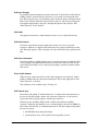
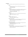
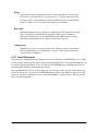
5.1.1 General Tab
This area contains information common to all serial ports on an EM1500.
Figure 5.2 General Tab of emconf
Unit name
The unit name is a text string chosen by the user to uniquely identify the unit. It may
be left blank if the unit is unnamed. A unit’s name will be displayed in the listbox on
the left side of the program window if the EM1500 responded during discovery.
Domain name
This is the DNS name of the unit. Currently this is not used for anything, but it should
be unique or left blank.
34
www.rabbit.com
EM1500 Configuration
Routers
This is where you specify the IP addresses of the routers that the EM1500 will use
when packets need to be forwarded outside of the LAN.
For most cases enter just the IP address of the router in dotted decimal form and leave
the mask and network entries zero. They are for the special case of two routers on the
same LAN. When there are two routers to choose from, the correct netmask values in
these fields allow for more efficient routing.
Name Servers
This is where you specify the IP addresses of DNS name servers. Specify IP addresses
in dotted decimal form.
Connection keepalive(s)
If a non-zero value is entered, TCP keepalives will be used to maintain the network
connection. A keepalive segment will be sent at the specified time interval (in
seconds). This allows a unit to recognize that the peer has terminated its end of the
connection without the usual notification. Note that use of this option will increase
network traffic.
Secure config
The EM1500 may be configured to use cryptography to prevent unauthorized changes
to the configuration. This protection only applies to configuration. The unit does not
currently support any protection of the data connections. Secure configuration is recommended if the EM1500 is to be connected to an Ethernet network which is accessible from the general Internet. It is not required if the unit is behind a firewall, or on an
isolated network, unless it is desired to protect the unit from other network users.
You enable secure configuration by checking the “Secure config” check box. When
you save the configuration to the target unit, you will see the unit's icon change from a
red open padlock to a green closed padlock. The configuration program running on
the PC generates a random key. The key is sent to the unit, and also stored in a file on
the PC. The key in the file is associated with the serial number (MAC address) of the
unit. Each unit will have a unique key.
Since all keys are stored in the file on the PC, it is critical to prevent unauthorized
users from accessing this file, and it is also critical that the file not be lost or deleted.
Once a unit is configured for secure configuration, it is not possible to reconfigure the
unit unless the key file is located and has the correct key. If the key is lost, then the
only alternative is to physically go and reset the unit to factory defaults.
EM1500 User’s Manual
www.rabbit.com
35
Windows (Secure config)
On MS Windows operating systems, the key file is stored in the installation directory,
under the EM1500RC subdirectory. The name of the file is
<install-dir>\EM1500RC\UNITKEYS.EMK
Even if you re-install the configuration program in another directory, it will always try
to access the same file (since the full name of the file is stored in the Windows registry). This is convenient since you do not want to lose the configuration keys just
because of a new configuration program version).
This file should be protected from access by unauthorized users. If the machine is to
be used by several users, or the file shared over a network, then after configuring all
the necessary units you should move this file to a secure backup and delete the original.
IMPORTANT: only one instance of the configuration program should be allowed to run at
any one time. If another instance is started, it will not be able to access the key file since the
key file cannot be shared amongst multiple users, or multiple instances of the same application. To enforce the single-use requirement, a lock file is created in the same directory, i.e.,
<install-dir>\EM1500RC\UNITKEYS.LCK
This file is created when the configuration program is started, and deleted when it finishes. If the program is terminated forcibly (e.g., by using the Task Manager) then this
file may be left in existence, which will prevent the configuration program from working correctly next time. In this case, you should manually delete the UNITKEYS.LCK
file, then restart the program.
Linux (Secure config)
Under 80x86 Linux, the key and lock files are stored in /etc/em1500rc. As root
user, you should create the em1500rc directory under /etc, and give this directory
read, write and execute (list) privileges to the user who will be running the configuration program. Access should be denied to other users (and/or groups). If this is not a
satisfactory key and lock file location, you can override the default locations by
changing some FOX library settings.
When the user starts the application for the first time, the FOX library creates some
files in the user's home directory, under a directory named .foxrc. In this directory,
a subdirectory for Rabbit products will be created. Under this directory will be a file
with registry settings for the emconf application, called EM1500. Thus, the settings
for each user are contained in the file
~/.foxrc/Rabbit/EM1500
You can edit this file and create two new entries to indicate where the unit keys and
lock file reside. Under the [SETTINGS] entry, add the following two lines:
sysKey="/home/em1500user/em1500rc/unitkeys.emk"
sysLock="/home/em1500user/em1500rc/unitkeys.lck"
36
www.rabbit.com
EM1500 Configuration
Change the path name to the desired file locations. The path name must be absolute
(i.e., start with a slash). If more than one user needs to configure EM1500s, then they
may share the same key file, or have different key files. If the key file is shared (e.g.,
if everyone uses the default key files in /etc/em1500rc) then only one user will
be able to use the configuration program at any time. This is because the same lock
file considerations apply to Linux as they do to Windows (see above).
If the user has her own private key and lock files, then there is no sharing restriction;
however, any units that she selects for secure configuration will not be accessible by
any other user, since other users will not generally have access to her key file.
Other considerations (Secure config)
When first set to secure configuration mode, the key is sent in clear text over the network. Thus, in principle, an unauthorized person may be able to capture the key. If
this is deemed to be a risk, then the unit should be initially configured on a network
that is known to be secure against snooping attacks.
The current firmware release does not support changing the key once it is set, except
by turning secure configuration off, then back on. The key is a 128-bit AES key, and
messages are protected with MD5 secure hashing. This combination is thought to be
secure against all but the most well-equipped agencies. Even so, a critical evaluation
of risk should be taken before the EM1500 is used in the field.
The security offered by secure configuration is only as good as the degree of protection afforded to the key file on the PC. Please note again that it is only the changing of
configuration data which is protected. Currently, the data links (i.e., ordinary operation) of the EM1500 are not secured.
WWW userid
User ID that must be supplied to access web-based configuration.
WWW password
Password that must be supplied to access web-based configuration.
Digest auth.
Check this option to require your browser to use digest authentication. Otherwise, the
browser will need to use basic authentication. If your browser supports it, it is more
secure to use digest authentication because passwords are not transmitted in plaintext.
NOTE: Digest authentication is supported by modern browsers only. In particular, Netscape
4.x does NOT support digest authentication.
EM1500 User’s Manual
www.rabbit.com
37
5.1.2 Aux I/O Tab
This tab reveals a screen of advanced options. The visibility of this tab is toggled by clicking on View |
Advanced.
Figure 5.3 Settings for Auxiliary I/O and SPDT Relay
Initial state:
Direction/State
This shows the initial data direction and output state of PF0-4 I/Os on boot-up. If
“SER3 uses PF0-3” is checked then only PF4 is available as an extra I/O line.
State
These parameters control the initial state of the 2 open-collector outputs of the
EM1500 on boot-up. They are set independently to “Pulled low” or “Hi-Z.”
Relay
This parameter controls the initial state of the SPDT relay on boot-up. It may be open
or closed. The relay may be used to cycle power on an attached device.
Note that the relay is non-latching. When the EM1500 is powered off the relay will
always be “open.”
38
www.rabbit.com
EM1500 Configuration
LED shows Tx/Rx state in run mode
Each serial port has a checkbox here. Check each one that you want to have effect the
user LED. When a serial port is checked here and the unit is in normal run mode, the
user LED blinks red when data is transmitted and blinks green when data is received.
Please note that there is only one bicolor LED for all of the serial ports; i.e., the user
LED will light up whenever one or more of the serial ports checked here is receiving
or transmitting.
The user LED also gives status for the unit as a whole. Please see Table 4.2 for a
description of the possible LED patterns.
5.1.2.1 Additional Information for Auxiliary I/O
The GUI allows you to change the initial state of PF0-4, OUT0, OUT1 and the relay, but it does not allow
you to change the initial state of the three digital inputs on the 9-pin connector. The default state is “pulled
up.” To change the state to “pull-down” means moving the zero ohm resistor at JP1, which will require
some soldering. For directions on how to access JP1, please see A.4, “EM1500 Jumpers.”
EM1500 User’s Manual
www.rabbit.com
39
5.1.3 Network Tab
This screen has information about the Ethernet interface. Most importantly, this is where you may assign a
known IP address to the EM1500. If you are using DHCP, an IP address entered here will be used as a
backup if the DHCP attempt fails.
Figure 5.4 Network Tab
IP address
To assign a static IP address to the EM1500 enter it in this text box. Make sure “Use
DHCP” is unchecked.
If “Use DHCP” is checked, any IP address entered here will be used as a fallback if
DHCP is not available.
IMPORTANT: If the EM1500 is no longer readily accessible (i.e., it’s no longer on
your desktop or maybe it’s not even in the same building) changing its IP address or
netmask should be done with great caution. It is possible to assign an IP address or
netmask to the unit that causes it to no longer be able to communicate across the
Internet. The only way to recover from this requires physically touching the unit to
reset it.
Netmask
Like an IP address, the netmask may be obtained from your network administrator. It
specifies subnetting of the IP address.
40
www.rabbit.com
EM1500 Configuration
Use DHCP
Use DHCP to obtain IP address and other network parameters. DHCP provides
dynamic allocation of network addresses. A DHCP server must be on the same LAN
segment as the EM1500 for the unit to succeed as a DHCP client. This option is
enabled by default.
If your EM1500 will act as a server out in the field, clients will need a known IP
address to contact. DHCP may still be used if the DHCP server is configured to recognize the EM1500, and (for example) always assign it the same IP address.
Ping configure
Check this to allow use of ping to assign the unit’s IP address. Please see Section 3.2.1
for a detailed description.
Enable web browser config
Check this to allow the use of a web browser for configuration. Please see the “General” tab for instructions on how to select a login name and password to limit access
by a web browser.
Enable config
This must be checked for the stand-alone program to communicate with the EM1500.
Enable discovery
This option allows the EM1500 to respond when it recognizes a specially-formatted
broadcast packet. The stand-alone program will send out such a broadcast packet
when it first starts and when the menu option Unit | Find all is chosen. (Keyboard
shortcut is <Ctrl+F>.)
If the EM1500 was previously configured by another host (by the setting of the
“Secure config” option) the unit will not reveal itself to anyone else unless they too
have the key. A directory on the host that secured the unit, contains the keys that
allow configuration access. Copying the directory and its contents to a new host gives
the new host configuration access.
EM1500 User’s Manual
www.rabbit.com
41
5.1.4 Serial Tab (for SER1 - SER4)
Each serial port is configured independently. The tabs along the top select one of the five serial ports,
while the seven tabs lined up vertically under the Network tab correspond to the different parts of the serial
port configuration.
Figure 5.5 Serial Tab of Stand-Alone Configuration Program
Except for flow control, the parameters shown on this screen apply equally to all of the serial ports.
Speed (BPS)
This is the serial port speed in bits per second. Choose from the drop-down menu with
choices ranging from 300 bps to 230400 bps. You may also enter any value between
75 and 230400 in this field. The number should match the data transfer speed of the
attached serial device.
The EM1500 serial ports may all be configured for a wide range of bit rates, including
non-standard speeds. The actual rates which are obtainable must be equal to the base
clock divided by an integer between 6 and 256 inclusive. The base clock is
1,382,400 Hz, giving a range of speeds from 5400 to 230400 bps. Speeds slower than
5400 bps may also be achieved: in this case, the base clock becomes 19200 Hz, which
may be divided by an integer between 4 and 256 inclusive. Thus the slow range of
speeds varies between 75 and 4800 bps.
Because of the requirement for an integer clock divider, the speed resolution is worst
at the highest speeds in each range. For example, the next speed below 230400 bps is
197486 bps (using a divisor of 7 instead of 6). The next speed below 4800 bps is 3840
bps (using divisor of 5 instead of 4).
In practice, all of the most common serial port bit rates are achieved exactly (within
the limit of the crystal oscillator accuracy, which is about 100ppm). Many of the less
common rates, such as 14400 bps, are also exact.
SER3 and SER4 have an upper limit of 115200 bps.
42
www.rabbit.com
EM1500 Configuration
Character size
This is the number of bits per character, not counting start, parity or stop bits. The
only valid entries for this field are 7 and 8.
Parity
Parity is the simplest way to check that transmitted data was received without errors.
The options are:
•
•
•
•
•
None: no parity check is done.
Space: the parity bit is always zero.
Mark: the parity bit is always one.
Odd: data bits plus the parity bit equals an odd number
Even: data bits plus the parity bit equals an even number
“Space” and “Mark” are seldom used parity methods because they are less likely to
reveal the existence of a garbled bit. Using “Odd” or “Even” for parity is more common. If you want 2 stop bits (only 1 stop bit is supported in the hardware), you may
simulate it in software by choosing “Mark” for parity. This looks like an extra stop bit
in the data stream.
NOTE: Data bytes received with parity error are not transmitted to the peer.
EM1500 User’s Manual
www.rabbit.com
43
Flow control Tx
Flow control can be set independently for both Tx and Rx directions, though in most
cases, the setting will be the same for both directions. Flow control ensures that no
data is lost during transmission.
The flow control options for the transmit line of SER1 are:
• None - no flow control on the transmit line. The receiver must be able to accept data at
the maximum rate.
• CTS (hardware) - CTS is an input to the serial port. When asserted it means that the
attached serial device can accept more data from the EM1500.
• XON/XOFF (software) - sent by the device receiving data to stop or restart the data flow.
• DSR (hardware) - an input to indicate that the attached device is ready.
• DCD (hardware) - an input that indicates when a remote modem has been detected on the
other end of the line.
The same options exist for SER3 when it is a 9-wire DTE device. Otherwise, DSR
and DCD are not available.
The Tx line is an input for SER2, the flow control options are:
•
•
•
•
44
None - no flow control on the transmit line.
RTS (hardware) - an input that tells SER2 when to stop and start data transmission
XON/XOFF (software) - sent by the device receiving data to stop or restart the data flow.
DTR (hardware) - input to detect the readiness of the attached device.
www.rabbit.com
EM1500 Configuration
Flow control Rx
The EM1500 can buffer up to 1020 characters. After that the network throughput
must be high enough to avoid dropped data.
The flow control options to control reception on SER1 are:
• None - No flow control on the receive line.
• RTS (hardware) - an output that tells the attached device when to start and stop data
transmission.
• XON/XOFF (software)
• DTR (hardware) - output to indicate that SER1 is ready.
These same options exist for SER3 when it is configured as a full DTE serial interface. If SER3 is not a full DTE serial interface, then DTR is not available to it.
Here are the options for SER2. Remember that Rx is an output because SER2 is a
DCE.
• None - no flow control on the receive line.
• CTS (hardware) - an output that tells the attached DTE when to start and stop data transmission.
• XON/XOFF (software)
• DSR (hardware) - an output to indicate that SER2 is ready.
• DTR (hardware) - an input to detect the readiness of the attached device.
EM1500 User’s Manual
www.rabbit.com
45
Relay action on open
When a connection is opened to this port from the network, one of the following
actions may be taken on the SPDT relay:
•
•
•
•
•
None
Latch on
Latch off
Momentary on
Momentary off
Relay action on close
When a connection is closed, one of the following actions may be taken on the SPDT
relay:
•
•
•
•
•
None
Latch on
Latch off
Momentary on
Momentary off
Relay timer (ms)
Relay timer for momentary actions.
NOTE: It is possible to enter contradictory or nonsensical settings for the relay.
For example, SER1 causes “Latch on,” and SER2 causes “Momentary on.” Normally only one serial port should specify relay actions other than “None.” Otherwise each action is taken at the point of opening or closing the network
connection. If the relay is already “on” (closed) then an action of “Momentary
on” will have the effect of leaving the relay on for the specified momentary
interval, then turning it off.
46
www.rabbit.com
EM1500 Configuration
5.1.5 Serial Tab for RS485
The RS485 serial port does not have hardware handshaking lines, so can not use any of the flow control
methods. However, since it is half-duplex, a transmitter enable discipline is defined.
Figure 5.6 Serial Tab for RS485
Tx Enable
Transmitter enable control used for half-duplex RS485. The choices are:
• None
• Rx Idle
Rx idle time (char times)
If “Rx Idle” was chosen for transmitter enable control, this parameter specifies the
time interval which Rx must be idle before the unit can enable the transmitter.
The relay configuration parameters are the same for the RS-485 port as they are for the other serial ports.
EM1500 User’s Manual
www.rabbit.com
47
5.1.6 Modem Tab
Any of the serial ports may be configured to look like a Hayes-compatible modem to an external device,
except for SER4. Since many existing devices expect to be able to talk to modems, this allows the device
be configured to “dial out” to hosts on the network.
The following screen capture shows configuration parameters for SER2. The parameters for SER1 and
RS485 are (mostly) a subset of these.
Figure 5.7 Modem Dialog for SER2
AT command set
Check this box to enable AT command emulation for the selected serial port.
See Table 5.1 for the list of AT commands emulated by the EM1500. Unless otherwise noted, it is assumed that the AT prefix has been provided. Commands can be
entered in upper or lower case. For the AT prefix, all uppercase or all lowercase must
be used (e.g., AT or at, but not At or aT). The following commands may have mixed
case.
After the AT prefix which starts each command line, any reasonable number of commands can follow (without repeating the AT prefix). Commands can be strung
together without spaces, or spaces can be used to delimit the commands (for readability). If commands are strung together, then those commands which do not take a
numeric parameter (such as H and Z) should have a dummy '0' (zero) parameter
appended after all but the last, e.g., ATZ0I0H<CRLF>.
If entering commands manually, e.g., via a dumb terminal, you can use the backspace
key (ASCII 8 or control-H) to edit the command line. The command line is terminated
by line-feed (LF), carriage return (CR), or both (CRLF). Any response strings generated are usually preceded and followed by CRLF.
This is an industry standard command set; however, most manufacturers have slight
variations from the original standard. The EM1500 is not a normal telephone line
modem, so many of the original AT commands are not relevant (such as whether Bell
or CCITT signalling is used).
AT command emulation is most useful for SER2, since that serial port looks “most
like” a modem to the external device: in particular, it has DCD and RI outputs, which
are not available on the other ports. AT command emulation is useful on the other
ports as well (except SER4); however, some of the commands will not be relevant
48
www.rabbit.com
EM1500 Configuration
such as the ones that are specific to modem control signals that are not actually available.
Rather than telephone numbers, the EM1500 uses IP addresses or host names to identify the “called party.” The ATDT command is used to set up a network connection to
another EM1500 or host, in much the same way as the ATDT command tells a standard modem to dial out on the POTS (Plain Old Telephone Service).
The advantage of supporting an industry standard command set is that legacy serial
devices that know how to talk to a modem can now talk to the EM1500 without knowing the difference. The serial device becomes “network enabled” without significant
work.
Table 5.1 Supported Command Set
Command
Action
A
Enter “auto answer” mode. The EM1500 waits for a network
connection to be made to the serial port. When a connection is
made, a CONNECT message is sent to the serial port then
normal data transfer is started.
D
Reconnect to the host that was last connected ('redial').
DL
Reconnect to the host that was last connected ('redial').
D domainname
Connect to specified domain name, e.g., “em1500.foo.com”
using the TCP port that was last used.
D domainname tcp_port
Connect to specified domain name, e.g., “em1500.foo.com”
using the specified TCP port number in the range 1..65535.
DT ipaddr
Connect to specified IP address using TCP port number that
was last used. The IP address is in decimal format, with 4
groups of decimal numbers in the range 0..255 inclusive. The
delimiter between each number may be any punctuation
character (usually a period).
DT ipaddr tcp_port
As above, but specify a particular TCP port number in the range
1..65535.
DP local
Connect to host specified by local configuration entry “local”
which is a number in the range 1 to 65536. “local” must match a
number that is specified in one of the “Opening” tab items in
the “Local TCP port” field. This may be the “Opening” entry
for any serial port, not just the one through which the AT
command is being issued. The configuration entry needs to be
set up with valid “Remote TCP port” and “Remote host”
definitions for this command to be useful.
E0
Disable echoing of AT commands
E1
Enable echoing of AT commands
EM1500 User’s Manual
www.rabbit.com
49
Table 5.1 Supported Command Set
Command
50
Action
H
Disconnect from remote host (“hang up”). Note that on standard
modems, this controls the hook switch. There is no concept of a
hook switch on the EM1500, so this always disconnects the
current connection if one is established: H0 and H1 have the
same effect.
I
Modem identification. This returns the string “EM1500 0.0”
with the appropriate firmware version and release number
substituted for the “0.0”.
O
Return “on-line” from AT command mode. If there is a
connection or pending connection, this gets out of AT
command mode and back to normal data transfer mode.
Q0
Disable quiet mode (i.e., respond with numeric or English result
codes)
Q1
Enable quiet mode (no responses)
V0
Use numeric result codes
V1
Use English word result codes
Z
Reset modem settings to defaults (see Default settings below)
&C0
DCD is always active (SER2 only)
&C1
DCD is asserted when a connection is opened (SER2 only)
&D0
DTR (SER2) or DSR (others) is ignored
&D1
DTR/DSR off switches from on-line (data transfer) to AT
command mode
&D2
DTR/DSR off causes connection to be closed
&K0
No flow control
&K1 or &K3
RTS/CTS hardware flow control
&K2 or &K4
XON/XOFF software flow control
www.rabbit.com
EM1500 Configuration
Table 5.1 Supported Command Set
Command
Action
&Kn
Other flow control: n is a number which has two fields:
The low 3 bits of n select the transmit flow control as follows:
0 = none
1 = CTS (or RTS for SER2)
2 = XON/XOFF
3 = DSR (or DTR for SER2)
4 = DCD (SER1, SER3 only)
The next higher 3 bits of n select the receive flow control as
follows:
1 = none
2 = RTS (or CTS for SER2)
3 = XON/XOFF
4 = DTR (or DSR for SER2)
5 = DCD (SER2 only)
Any values that are not listed here default to “none.”
&S0
DSR (SER2) or DTR (others) always asserted
&S1
DSR/DTR asserted when connection is established
This character sequence, preceded and followed by at least one
second idle time, causes an active session to be temporarily
interrupted and Hayes modem mode entered.
+++
Default settings
The following settings are in effect by default, or after an ATZ command:
• E1: Echo AT commands
• &C, &D, &K, &S: Flow control and modem handshake lines set according to
the configured defaults
• Q0: Issue response codes
• V1: Issue English word response codes
DTR Control1
This is where you specify how to use the DTR modem control line. This is only applicable if the line is not being used for hardware flow control, and the serial port has
modem control lines which include this signal, i.e., SER1, SER2 and possibly SER3.
The choices are:
• Active - always asserted
1. This control may be overridden by AT commands or by RFC2217 control.
EM1500 User’s Manual
www.rabbit.com
51
• When connected
• Inactive - never asserted
• When not in Hayes-modem command mode
NOTE: for SER2, this is DSR control.1
RTS Control1
Specify how to use the RTS modem control line. This is only applicable if the line is
not being used for hardware flow control, and the serial port has modem control lines.
The choices are:
• Active - always asserted
• When connected
• Inactive - never asserted
NOTE: for SER2 this is CTS control.1
DCD Control (for SER2 only)
Specify how to use the DCD modem control line. This is only applicable if the line is
not being used for hardware flow control.
The choices are:
• Active
• When connected
• Inactive
RI Control (for SER2 only)
Specify how to use the RI modem control line.
The choices are:
• Inactive
• Pulse for 1 second when connection first established
5.1.6.1 Modem Tab Parameters for SER3 and SER4
The configuration parameters available on the Modem tab for SER3 and SER4 differ from the other serial
ports for several reasons. First, although SER3 and SER4 are 3-wire RS-232 ports by default, they can be
changed to have TTL-level signals by changing jumpers on JP2 or JP3 respectively. Second, SER3 is configurable as a 5- or 9-wire port. Either of these configurations preclude the use of SER4 as a 3-wire port.
Third, in a future release of the EM1500, an internal modem will be available that will use SER4 even
when SER3 is configured as a 5- or 9-wire port. The configuration program refers to this future option on
the Modem tab for SER3 and SER4; however, it is not currently available.
52
www.rabbit.com
EM1500 Configuration
Figure 5.8 Modem Tab Configuration Parameters for SER3
The following table will clarify the different permutations of SER3 and SER4 and show how to achieve
them.
Table 5.2 Modem Tab Configuration Options for SER3 and SER4
SER4 is
internal
SER3 uses
9-wire
control1
modem
0
0
0
RS232
JP32
JP23
x
A
D
0
x
B
D
0
0
x
A
E
0
0
x
B
E
0
1
1
C
D
1
levels1
Comment4
SER3 true 3-wire RS232
SER4 true 3-wire RS232
SER3 true 3-wire RS232
SER4 3-wire TTL
SER3 3-wire TTL
SER4 true 3-wire RS232
SER3 3-wire TTL
SER4 3-wire TTL
SER3 5-wire RS232, true 3-wire
(RTS/CTS are 0-3V, Tx, Rx are +/-5V)
SER4 is internal modem
0
1
1
0
0
1
C
A
E
D
SER3 5-wire TTL
SER4 is internal modem
SER3 9-wire RS232, true 5-wire (DSR,
DTR, DCD, RI are 0-3V, Tx, Rx, RTS,
CTS are +/-5V)
SER4 not available
1
EM1500 User’s Manual
0
0
B
E
SER3 9-wire TTL
SER4 not available
www.rabbit.com
53
Table 5.2 Modem Tab Configuration Options for SER3 and SER4
SER3 uses
9-wire
control1
SER4 is
internal
modem
1
1
1
RS232
levels1
1
JP32
C
JP23
D
Comment4
SER3 9-wire RS232, true 3-wire (RTS,
CTS, DSR, DTR, DCD, RI are 0-3V, Tx,
Rx are +/-5V)
SER4 is internal modem
1
1
0
C
E
SER3 9-wire TTL
SER4 is internal modem
1. “x” means don’t care;
“0” means the configuration parameter is unchecked;
“1” means the configuration parameter is checked.
2. JP3 is an internal jumper setting:
A means JP3 is jumpered on 1-3 and 2-4, i.e., SER4 is RS232 on 10-pin,
B means 3-5 and 4-6, i.e., SER4 is TTL on 10-pin
C means 7-9 and 8-10, i.e., internal modem installed (future option), use PD4/5 on 10 pin for
CTS/RTS
3. JP2 is internal jumper setting:
D means JP2 is jumpered on 1-3 and 2-4 i.e. SER3 is RS232
E means 3-5 and 4-6 i.e. SER3 is TTL)
4. 3-wire means just Tx, Rx
5-wire means Tx, Rx, CTS and RTS
9-wire means Tx, Rx, CTS, RTS, DSR, DTR, DCD, RI.
Prefixed with “true,” means that all N-wire signals are true RS232 levels. Without the “true”
the port may be used in controlled conditions with N-wire RS232 equipment, but is not guaranteed to work since not all of the N wires are at correct standard levels.
5.1.7 Polling Tab
This is an advanced setting that is only visible when View | Advanced is checked. The same polling
options are available on all 5 serial ports.
54
www.rabbit.com
EM1500 Configuration
Figure 5.9 Polling Tab
The polling facility allows a device attached to an EM1500 serial port to be regularly queried. Polling can
be used to periodically
• collect data from the device and/or
• check the state of health of the device and/or
• tell the device that it is still connected to something.
Polling options are entered under the “Polling” tab for each serial port. It is necessary to check the “Enable
poll” option to enable any polling. When checked, a number of other options become enabled. These
options are described below.
Note that polling is inserted by the EM1500 at arbitrary points (from the point of view of the attached
device or network peer). Thus, if you select the “Poll when connected” option, there may be undesirable
interaction with the normal data stream. In this case, you may want to select some form of packetization
for the connection. If packetizing is in use, then polling only occurs between successive packets. This is
less likely to cause interference. Also, each “send” string in the polling sequence will be sent as a single
packet to the serial port.
Enable poll
Enable device polling sequence. Checking this option makes the rest of the polling
options available.
EM1500 User’s Manual
www.rabbit.com
55
Poll pass-through
Pass polling responses through to network connection. If checked, the results from the
polling sequence (generated by the serial device) are passed over the network to the
peer. Thus, the peer gets to see the polling results, but not the queries which generated
them. If not checked, neither the queries nor the results are sent to the peer, thus polling happens transparently to the peer. Checking this option is only useful if “Poll
when connected” is also checked.
Poll initial
This option is reserved for a future firmware release. Leave it unchecked for now.
Poll fixed interval
If checked, the poll interval timer applies between the start of successive poll
sequences. Otherwise, it applies between the end of one sequence and the start of the
next. If the poll sequence takes a long time, the latter will result in fewer polls per unit
time.
Poll when connected
If checked, polling is applied whether or not a network connection is established. Otherwise, polling is only performed when there is no network connection. This is most
useful when packetizing is in use, otherwise the polling can interfere with the normal
data stream.
Close if poll timeout
When checked, connection will be closed if poll script times out. Otherwise, further
polling is inhibited but the connection remains open. This is only applicable if “Poll
when connected” is checked.
This checkbox is also available in the “Closing” tab.
Poll interval (ms)
Interval between polling. If “Poll fixed interval” is checked, this is the time between
the start of one poll sequence and the start of the next. Otherwise, it is the interval
between the end of one poll sequence and the start of the next.
Poll interval (ms) should be filled in with a suitable interval between polling
sequences. Normally, this should be set to a reasonably high value such as 60000 (for
60 seconds). Note that this is a minimum time interval. The time might be longer than
this for two reasons:
• the EM1500 is busy doing other things
• packetization is in use, and a packet has been partially received
56
www.rabbit.com
EM1500 Configuration
Poll timeout (ms)
Poll sequence must complete within this timeout. “Poll timeout (ms)” specifies the
allowable time interval for the device to completely respond to the poll sequence. If it
does not respond, then the poll sequence has failed. When it fails, the next poll
sequence is not affected, but the EM1500 can be configured to close a connection if
this happens.
Poll script
Poll script specifies the polling sequence in send/expect script format. This is a string
that is entered with the syntax described below, in the order of send string followed by
expect string. In the simplest case, you can just set this to a send-string without any
expected response. This would send the string out the serial port at regular intervals,
but not look for any particular response. For example, the send string could be just
“\r\n” (carriage return + line feed). This would be equivalent to hitting the return key
regularly if a terminal was connected to the device rather than the EM1500. Since no
particular response is expected, the script will never time out. If the device sends some
data back in response to CRLF, then that data will be forwarded over the network (if a
connection is established).
The next level up in complexity is to actually expect a particular response to a query.
For example, if the device is set up so that if it gets “HELLO<CRLF>” then it
responds with “OK”, then the following poll sequence could be used:
'HELLO OK'
A space separates the send and expect portion. Note that a CRLF is added by default
to the send string, so it should not be explicitly specified.
This sequence executes as follows:
• The EM1500 sends the string “HELLO<CRLF>” to the serial port.
• The device may be in the process of sending previous data. This data is intercepted by
the EM1500 while it is looking for the OK response. The data will be discarded, or may
be passed through to the network peer.
• The device eventually receives the HELLO string and sends the OK response.
• The EM1500 will see the OK response. It absorbs the OK (unless pass through is
enabled), then starts passing on the data immediately following the OK as per normal.
Poll Script Syntax
The full syntax for specifying the poll script is as follows:
[ send expect ]...
where “send” is a token to send, and “expect” is a token to expect in return, before the
next send/expect pair is executed. Either “send” or “expect” may be omitted; use
empty single quotes as a place-holder.
EM1500 User’s Manual
www.rabbit.com
57
Special Characters in a Token
If an expect token starts with an “&” character, this has special meaning: the “&” is
stripped off the expect token, and no timeout is applied. This is useful for “auto
answer” scripts where there is an indefinite wait time.
If a send token is prefixed with “#” then the CRLF that is normally appended to the
token, when sent, is suppressed. To send just a CRLF, specify “#\r\n” as the send
token.
If an expect token is prefixed with “#” (after the “&”, if any) then the comparison is
performed in a case-insensitive manner, otherwise the expect token must be matched
exactly. No CRLF is expected, unless you explicitly specify it, e.g., “login:\r\n”.
Either a send or expect token may be prefixed with “@” (after the “&” or “#”, if any).
This sets a pause timer of 1.5 seconds which has to time out before the send token is
sent, or before incoming data are examined for matching the expect token. Incoming
data are discarded during the pause interval, so this feature should be used with caution when prefixing an expect token, since the expected data may be discarded during
the pause!
The token sequence is separated by white space. If it is desired to include whitespace
in a token, then the token should be wrapped in single quote characters.
A backslash (\) character in a token denotes an “escape sequence” for inserting special
characters, as follows:
\nnn
From 1 to 3 octal digits (0-7). This sequence represents the octal value
of a character e.g. \377 represents the decimal character number 255;
\1 represents control-A. If fewer than 3 octal digits are intended, then
the next character must not be an octal digit.
\r\n
Represents carriage return followed by newline. Other special characters modelled after C syntax: \r CR; \n NL; \b BS; \t TAB; \f FF.
Any other character following the backslash stands for itself, e.g., \\ specifies a single
backslash, \' stands for a single quote. A single backslash at the end of a token is a
syntax error.
String sizes
Send and expect strings are limited in size to 30 characters.
This size is counted after performing any escape sequences and string substitutions.
You must be careful not to exceed this limit since there is no indication of exceeding
this limit: any extra data are quietly discarded and only the first 30 characters will be
matched.
Error handling
If the script has syntax errors, they may not be discovered until the script executes.
Current syntax errors are unbalanced quotes and trailing unescaped backslash. If there
is an error in the script, then polling will be turned off.
58
www.rabbit.com
EM1500 Configuration
5.1.8 Opening Tab
Where and when a serial port is open for communication is decided here. The following screen is for
SER1, but the rest of the serial ports have basically the same parameters to set. In fact, SER3 configured as
a 9-wire port has exactly the same parameters as SER1. The rest differ in the choices for “Incoming connections” and “Active open.”
Figure 5.10 Opening Tab for SER1
Local TCP port
This is the local TCP port number for incoming connections from the network. When
acting as a server, this is where the serial port listens. Set to zero to make this entry
unused. Port numbers less than 1024 are reserved; they are used for internal functionality and standard services such as web server and telnet.
Table 5.3 Default Port Numbers
EM1500 Serial Port
EM1500 User’s Manual
Responds to TCP Port #
SER1
8888
SER2
8889
SER3
8890
SER4
8891
SER5
8892
www.rabbit.com
59
Remote TCP port
Remote TCP port number for outgoing connections to the network. This is a default
which may be overridden by ATDT commands.
Remote host
Host name or IP address of default remote peer to connect to when an outgoing connection is initiated. May be overridden by ATDT commands.
Ephemeral port
When checked, outgoing connections use a local ephemeral TCP port number. Otherwise “Local TCP port” is used.
Check this option if the EM1500 is acting as a client on this serial port.
Use Nagle
When checked, TCP connections buffer outgoing data using the Nagle algorithm.
This is recommended for most applications. If turned off, latency will be reduced at
the expense of greater network bandwidth requirements.
Don’t Purge
When checked, data received by the serial port before a connection is established will
be sent to the peer. If not checked, then pre-connection data is discarded.
Check this option if you are using polling and want to talk to the serial device off-line.
Approximately 1020 data bytes may be buffered while not connected. Additional data
is discarded until a connection is established.
Incoming connections
Select when to listen for incoming connections from the network. The choices are:
• Never accept - This port will not be a server, but can be a client.
• Always accept - This port will automatically listen for incoming connection requests.
• Accept when DSR - This choice only applies to SER1 or SER3 configured as 9-wire
DTE. It is a signal from the attached device saying that it is ready.
• Accept when DTR - This choice only applies to SER2. It is a signal from the attached
device saying that it is ready.
60
www.rabbit.com
EM1500 Configuration
Active open
When to actively open a connection to another unit over the network. The choices are:
Always
Always open, or “nail up.” This is only available if incoming connections are
never accepted (see above).
Available on all serial ports.
When DSR
Open when DSR/DTR line becomes active. This is not applicable if incoming connections are accepted when the same DSR/DTR line is active (see above).
This is available on SER1 or SER3 as 9-wire port.
“When DTR” is available on SER2.
When DCD
Open when DCD line becomes active. DCD indicates good carrier from remote
modem.
Available on SER1 and SER3 as 9-wire port.
When RI
Open when RI line becomes active.
Available on SER1 or SER3 as 9-wire port.
When any char received
Open when any character is received. If “Don’t purge” is checked, the character
will be sent to the peer when the connection is established.
Available on all serial ports.
When specific char received
Open when specified character is received. The character and any previous data
are purged whether or not “Don’t purge” is checked.
Available with all serial ports.
Char to open (decimal)
If specific character causes open, this is the character. Specify a decimal number 0
thru 255. For example, “13” for carriage return or “10” for line feed.
Available with all serial ports.
EM1500 User’s Manual
www.rabbit.com
61
5.1.9 Closing Tab
A serial port can close for a variety of reasons. The “Closing” tab dialog box is where you may control the
parameters that affect this action. All of the serial ports have “Close delay” and “Reopen delay” in common. The differences lie in the “Close when” choices.
Figure 5.11 Closing Tab
Close when
When to close a connection. The choices are:
DSR dropped
Close when DSR line is dropped. Available with SER1 and SER3 configured as a
9-wire port.
“DTR dropped” is available on SER2.
Both DSR and DTR are used by attached serial devices to indicate that they are
ready.
Modem control, not close on DSR drop
When DSR/DTR line is dropped, escape to modem control mode. This only works
if modem emulation is selected for the serial port. Instead of closing the connection, the modem goes from data mode to control mode. Control mode is also
entered on receipt of the escape sequence, +++.
Available with SER1 and SER3 configured as a 9-wire port.
“Modem control, not close on DTR drop” is available on SER2.
DCD dropped
Close when DCD (RLSD) line is dropped. Available with SER1 or SER3 configured as a 9-wire port.
62
www.rabbit.com
EM1500 Configuration
Poll timeout
The serial port connection will close if the polling sequence did not complete
within the specified amount of time. Checking this option will automatically check
the “Close if poll timeout” option on the “Polling” tab and vice-versa. If you check
this option you must also fill in the poll timeout value on the “Polling” tab.
Available on all serial ports.
Network timeout
Close the serial port connection if the network peer fails to respond. The network
peer is identified either by the remote host and TCP port number on the “Opening”
tab or by the IP address given in the ADTD command if the modem emulation
software is active on this serial port.
Available on all serial ports.
Timeout (ms)
This field may be filled in when “Network timeout” is checked. It is the number of
milliseconds that may elapse while waiting for a response from the network peer.
Available on all serial ports.
Close delay (ms)
After one of the above conditions is detected, delay by this number of ms before closing the connection. The close condition must persist over this time interval, otherwise
the connection remains open.
Reopen delay (ms)
Delay before reopening, after a close. Specify the number of milliseconds to wait after
a connection request is made before action is taken.
Set this to at least a few thousand ms to prevent excessive network traffic in the case
that something is misconfigured, e.g., the connection gets a close condition immediately after opening.
EM1500 User’s Manual
www.rabbit.com
63
5.1.10 Protocol Tab
This is an advanced setting that is only visible when View | Advanced is checked. This is where you
enable a serial port to be compatible with PC COM port redirectors. This is also where you specify packetization options.
Figure 5.12 Protocol Tab (all 5 serial ports have the same options)
Modem Server
When checked, incoming connections will see this as an RFC2217 modem server.
Otherwise, a raw data link is established.
NOTE: This should be checked if you want to use a COM port redirector on a host PC to
allow the PC to talk to the serial port as if it was a local serial port.
Rabbit extensions
When checked, try to negotiate Rabbit extensions to RFC2217 protocol. This is recommended when connecting two EM1500s for use as a transparent serial bridge. If
the peer does not understand the extensions, this option will not cause any problems.
This is required if any packetizing options are specified.
64
www.rabbit.com
EM1500 Configuration
Packetizing
This is where you specify when to send data packets to the network. Since packetization options are an extension to the standard protocol (RFC2217), it is necessary to
check the 'Rabbit extensions' option.
The available modes are:
• None. No packetizing is required, e.g., for a purely stream-based application.
• Idle. Uses idle time (i.e., no data being sent or received for a specified time interval) to
delimit one packet from the next. Idle packetization requires specifying two timing
parameters (see below). Packet length should not exceed the size of the internal buffer.
• String Send/Cut. Packet terminated by a fixed character string. With this mode, there is
no length limit on the packet.
• 9th bit. Unlike “String” mode, which recognizes the end of packet, 9th bit mode looks
for the start of the packet. A packet is started by a 9th bit low. This is not compatible with
normal parity checking—any parity setting in the “Serial” tab is ignored.
Idle time units
Units in which following timeouts are set. The units may be ms (milliseconds), byte
(character times), or bit (bit times).
Available when “Idle” is chosen as the packetizing option.
Rx idle time
Specifies minimum time that serial port receiver must be idle to indicate end-ofpacket and to cause packet to be sent to network. Note that the value entered here is
rounded up to the nearest multiple of 1/32768 seconds (i.e., about 30 µs).
Available when “Idle” is chosen as the packetizing option.
Tx idle time
Minimum time that serial port transmitter is idle before sending new packet to serial
port. This value is rounded up to a multiple of 1/2048 seconds (i.e., about 488 µs).
Available when “Idle” is chosen as the packetizing option.
EM1500 User’s Manual
www.rabbit.com
65
String
String which defines end of packet. It may be of any length between 1 and 8 characters, however, it will typically be 1 or 2 characters (e.g., carriage return or line feed).
If “String - send” is selected, then the string is transmitted over the network with the
packet. If “String - cut” is selected, then the string is not transmitted.
Max buffer
Maximum number of bytes to buffer before sending packet. The upper limit is 1,020
bytes. If this limit is reached before the appropriate end-of-packet condition is
detected, the buffered data is transmitted without an EOP (End-of-Packet) marker.
This will have undesirable effects if “Idle” packetization is selected.
Trailing chars
Additional bytes (0 to 8) to send at end of packet. This may be used if checksum follows terminating string etc. It should only be used for “String” packetization, otherwise the results are undefined.
5.1.11 Status/Debug Area
The stand-alone configuration program supports some basic monitoring of the EM1500 devices accessible
over the network connection. The listbox at the top left of the display shows a list of the EM1500s that can
be contacted (among other things). If you click on one of the EM1500 icons to highlight it, then the area
below the listbox becomes a status display for that unit.
Only one EM1500 unit can have its status displayed at any one time (unless you start another instance of
emconf or emconf.exe). Also, the selected EM1500 will only send its status update messages to one GUI
instance at any time. If somebody else selects the same EM1500 for viewing, then you will lose your display (or it will stop updating).
66
www.rabbit.com
EM1500 Configuration
When you click on the EM1500 icon to select it, the GUI sends a message over the network to the selected
unit, telling it to send status updates on a regular basis, or when anything changes. After that, the EM1500
is responsible for sending messages to the GUI so that it can update the display in “real time.” This works
best for local LAN connections, but can also work over the Internet with, usually, a reduction in response
times.
The listbox and status/debug area are pictured below. One EM1500 responded to the broadcast, so only
one unit shows up in the listbox. It has been selected, which causes information for all of the serial ports to
display in the status window.
Figure 5.13 Status Area of Stand-Alone Configuration Program
It is divided vertically into six areas that we will refer to as trays.
Some of the items on the display are “buttons” and some are just “labels,” which we will call “LEDs.”
Both buttons and LEDs display in different colors to indicate the status of that control.
EM1500 User’s Manual
www.rabbit.com
67
5.1.11.1 Auxiliary I/O and Relay Tray
The first tray applies to the auxiliary
I/Os and the relay. This is labelled as
“AUX.” All of the controls are buttons.
The button color indicates whether the
control is currently an input or output, and its state on bootup. Green indicates an input, and orange indicates an output.
For the relay, a bright color indicates the it is closed, a dark color indicates it is open. For In0-2, a bright
color indicates the state on bootup is high, a dark color indicates it is low. For Out0-1, a bright color indicates the state on bootup is Hi-Z, a dark color indicates it is pulled low. For PF0-4, a bright color indicates
the state on bootup is high, a dark color indicates it is low.
If you click on a button, a message will be sent to the EM1500 to change the state of the control. If it can
change the control, the EM1500 responds with a confirmation message that updates the display. For example, if you click the “Relay” button, the relay will toggle and the button will change color. The button may
also change color in response to other events that cause the control to change state.
The AUX buttons all toggle the state of the specified I/O line or the relay.
5.1.11.2 Serial Port Trays
Below the AUX tray are the trays for
each serial port. Each serial port tray contains mainly status information, with buttons to manually override some
functions.
The status indicators show the state of
each of the modem control lines that are actually available, as well as whether data is being transmitted or
received. On the top row are 3 indicators and 3 buttons. The indicators are:
• TxD: shows whether any data has been transmitted to the serial port since last update.
• RxD: shows whether any data has been received from the serial port since last update.
• Flow: if illuminated (yellow), this indicates that the EM1500 cannot currently transmit data to the
serial device. Note that the opposite flow control, i.e., the EM1500 stalling the device from transmitting, is not currently shown in the display. Note that for the RS485 port, this indicator is labelled
“Txen” for “transmitter enabled” — this is the equivalent function for the RS485 port, since it is
half-duplex and does not have flow control in the usual sense.
The indicators below the first row show the status of each modem control line. SER1 and SER2 also have
a “NoC” indicator. This indicates whether any device is attached to the serial port. If no device is attached
(or the device is not powered up) then there will be zero volts on each of the serial port input lines. In this
case, the serial port driver detects that there is no connection. Otherwise, at least one of the lines will have
at least +/-3 V applied, in which case the no connection indicator (NoC) is turned off. Only SER1 and
SER2 support this feature.
68
www.rabbit.com
EM1500 Configuration
The manual controls are:
• M/C: this forces the EM1500 into or out of Hayes modem emulation mode. You should not do this
if a connection is currently open, since it may confuse the device attached to the serial port.
• Poll: pressing this button initiates a polling sequence.
• Conn: pressing this forces a network connection to be opened (if not already open) or closed (if currently open). If opening a connection, the default destination parameters from the 'Opening' tab of
the serial port are used. If closing a connection, then the connection is aborted ungraciously. The
peer that is currently connected will receive a TCP reset command that will cause it to abort its connection. Depending on configuration, either or both peers may try to initiate a new connection automatically.
These controls are mainly useful while testing and debugging a configuration. It is often useful to be able
to manually cancel a connection, since sometimes one of the peers can get confused (or crash)—in this
case, the connection sometimes gets “stuck” which requires a manual reset.
The text display on the 3rd and final line shows the current serial port setup (including speed, data bits,
parity, flow control and overall connection state). The first and second fields show speed and “geometry”
of the port. The third field is two letters separated by “/” which show the current transmit and receive flow
control:
Table 5.4 Transmit and receive flow control status
Symbol
N
Meaning
No flow control
C/R
CTS/RTS hardware flow control
S/T
DSR/DTR
D
DCD
X
XON/XOFF software flow control
The fourth field is a word which describes the connection state to the network:
Table 5.5 Connection state to the network
State
Init
wDNS
Meaning
Initializing
Waiting to start domain name resolution
DNS
Waiting for domain name resolution
Setup
Starting to open TCP connection
Opening
Waiting to open TCP connection
Ready
IP address
Listening for incoming TCP connection
Dotted decimal IP address of peer when successfully connected. This
is also followed by the TCP port number on the peer.
wClose
Starting to close connection
Closing
Waiting to close connection
EM1500 User’s Manual
www.rabbit.com
69
Table 5.5 Connection state to the network
State
Meaning
Failed
Detected error in connection
wAbort
Starting to abort connection
wInit
Starting to re-initialize
wOpen
In waiting period prior to reopening
wClose
In waiting period prior to starting to close
To the right of the text field, there are 4 bar graph displays arranged in a 2x2
matrix. These displays give an indication of how much the various internal
buffers are being utilized. These displays are interpreted as follows:
On the left side (the side with the arrow heads) you can imagine the serial
port. On the right side, imagine the network. [You can remember this because it is the same order as
the text field which contains the speed (serial port parameter) on the left, and IP address (network
parameter) on the right.] The arrow head shows the direction of data transfer: the top shows data coming from the serial port and out to the network. The bottom shows data from the network going to the
serial port.
The bar graphs show how much of the buffer is used. The left side bars show the serial port buffers
(both of which contain a maximum of 1020 characters). The right side bars show the network buffers
(which contain approximately 4k of data).
You can use these bar graphs, and the status indicators, to debug a problem with data flow. For example, if
you have set up SER2 to use hardware flow control, and the attached serial device has somehow become
unresponsive, this is what will happen:
The serial device has some sort of processing backlog, so it drops its RTS signal. The SER2 RTS LED
will go off. This prevents the EM1500 from transmitting more data out of its serial port. Thus, the
Flow LED will come on (yellow) indicating a flow control stall. If data is still coming in from the network, that data will back up in the serial port transmit buffer (lower left). When this becomes full, the
network buffer (lower right) will also start backing up. When this too fills up, the network peer, that is
generating the data in the first place, will not be able to send any more data over the network. This
may cause it to exercise flow control on its serial device, but that's another story.
Hopefully, this situation will not last too long. When the first serial device eventually finishes processing its backlog, it will reassert its RTS. The EM1500 will not be stalled any more, so the Flow LED
will go off. Now the serial port transmit buffer will start draining. The bar graph will diminish, but
sometimes go up again if data is staged from the network buffer to the serial transmit buffer.
At the very bottom of the GUI window, there is a text log of events. This is useful for debugging. Most of
the messages are self-explanatory. You can copy and paste from this text field into an email if required by
technical support.
70
www.rabbit.com
EM1500 Configuration
5.2 Differences between Configuration Methods
There are four significant differences between using the web browser for configuration and using the
stand-alone program.
1. A web browser requires you to know a valid IP address for the EM1500 before it can be contacted. The
stand-alone program can make contact with an EM1500 on its same LAN prior to an IP address being
assigned to the unit.
2. The “Secure config” option on the “General” tab of the stand-alone program is not available when
using the web browser. The ability to enable/disable encryption of the configuration data using a
browser would make the unit vulnerable to tampering.
3. Along the same lines as #2, the setting of a login name and password can be done from the stand-alone
program only.
4. Multiple units may be configured during one session with the stand-alone program. A web browser may
only point to one unit at a time. Of course, you can always open multiple browsers
Beyond the fact that you submit an HTML form via HTTP when using a web browser for configuration, as
opposed to the stand-alone program’s more direct method of sending a configuration packet via TCP, the
other differences between the two configuration methods are mainly cosmetic.
The status/debug area of the stand-alone program is always visible on the left-side of the program window.
When using a web browser, you must click on “Connections” to access the HTML form containing the
equivalent status and control buttons.
To the left of “Connections” is a link labeled, “About.” This displays some information about the
EM1500, including its MAC address.
EM1500 User’s Manual
www.rabbit.com
71
72
www.rabbit.com
EM1500 Configuration
6. EM1500 EXAMPLES
This chapter walks through two basic examples.
6.1 Example 1: Test Data Flow
This is an example of using two EM1500s connected serially to a PC to exercise the serial-to-Ethernetand-back-to-serial activity of the units.
You will need:
• Two EM1500s
• Two free COM ports on a PC running terminal emulation software.
• Ethernet cross-over cable to connect the Ethernet ports of the two EM1500s
• Two serial cables to connect the PC COM ports to the EM1500s. SER1 needs a
DE9 female null-modem cable, while SER2 requires a straight-through M-F cable.
First you must change the default settings on the EM1500s. The units must be configured with the following goals:
• to enable them to accept incoming connections from the PC COM ports
• to talk to one another over Ethernet
Use your preferred configuration method to display the options for opening the serial port. Fill in the
“Remote host” field with the IP address of the other EM1500. For “Active open” check “When any char
received.” Make sure DHCP is disabled. Do this for both units.
Using serial cables, connect either SER1 or SER2 from each EM1500 to the free PC COM ports. Then
using the Ethernet cross-over cable, connect the Ethernet ports of the two units and supply power.
On the PC, open up two instances of a terminal emulator, one for each COM port. Each PC COM
port/EM1500 serial port pair must have matching serial port geometry, e.g., 8N1, as well as matching
speed and flow control settings. The settings for each port in the pair, while having to match with one
another, do not have to match the settings in the other pair of serial ports.
Now, whatever you type in one terminal emulator window travels out its COM port, through the serial port
of the EM1500, out its Ethernet port to the Ethernet port of the other EM1500, out through that EM1500’s
serial port, in through the second COM port and almost instantly is displayed in the other terminal emulator window.
Even though this is a trivial example, one can extrapolate and see how it can be extended to something
useful. The data flowing across the Ethernet cross-over cable could just as well travel the company LAN
or the Internet.
EM1500 User’s Manual
www.rabbit.com
73
6.2 Example 2: Remote Data Acquisition
This example describes using an EM1500 to transfer data received on a serial line to a remote host, where
the data is automatically entered into an Excel spreadsheet. This simulates gathering data from a serial
device, such as a bar code reader, and sending it to a remote destination for processing.
You will need:
• One EM1500, configured as described in the next section.
• One PC with a free COM port, running terminal emulation software.
• One PC with an Ethernet interface, running TCP-Wedge1 and Excel (or any Windows application that is compatible with TCP-Wedge). This PC can be the same
PC with the free COM port running the terminal emulation software.
• One serial cable to connect the PC COM port to the EM1500. SER1 needs a DE9
female null-modem cable, and SER2 requires a straight-through M-F cable.
• Access to an Ethernet network from the PC and the EM1500. A likely scenario is a
hub to which the PC and the EM1500 are both connected.
The EM1500 must be configured with the following goals in mind:
• to accept data from a serial device
• to act as a client to transmit data to TCP-Wedge
6.2.1 Configuration Settings for EM1500
Use the stand-alone program emconf to configure the EM1500. The serial port speed and geometry must
match on both sides of the serial connection.
The Serial tab for SER1 or SER2 is set to:
• Speed: 115200 (this is arbitrary, provided the PC COM port is set to the same value)
• Character size: 8
• Parity: None (also arbitrary provided the PC COM port is set to the same value)
• Flow control Tx: None (also arbitrary, provided the PC COM port is set to the same value)
• Flow control Rx: None (also arbitrary, provided the PC COM port is set to the same value)
• Relay action: (not required)
1. TCP-Wedge accepts data from a TCP port and puts it directly into any Windows application. This product
is available from www.TALtech.com.
74
www.rabbit.com
EM1500 Examples
The Opening tab for SER1 or SER2 is set to:
• Local TCP port: 8889 (the default will do)
• Remote TCP port: set this to the port number where TCP-Wedge is listening.
• Remote host: set this to the IP address of the host PC where TCP-Wedge is running
• Ephemeral port: arbitrary
• Use Nagle: arbitrary
• Don’t Purge: arbitrary
• Incoming connections: Never accept
• Active Open: When any char received
Since the EM1500 will act as a client, you don’t need to have a static IP address if you have a DHCP
server available to the EM1500. In this case, you may check Use DHCP on the Network tab to have a
dynamically assigned IP address. (The Network tab is also where you identify a statically assigned IP
address, which you may do instead of or in addition to DHCP.)
These settings cause the EM1500 to request a connection from the remote host when it first receives a
character on its configured serial port. Unless a closing condition occurs, the connection will, theoretically,
remain open forever.
6.2.2 Hardware Connections
Using a serial cable, connect either SER1 or SER2 to the free PC COM port. Now you need access to a
network. The EM1500 must be connected via its Ethernet port to a network to which the host PC is also
connected. It can be a small desktop LAN that you create with a hub and some crossover cables or an
already existing network. (If the host PC is not on the same LAN as the EM1500, you will need to fill in
the router information on the General tab in addition to the parameters described above.)
6.2.3 Software Setup
After the EM1500 has been configured, there are three additional programs to run:
• Terminal emulator (e.g., Tera Term) - simulates a serial input device, such as a bar code reader.
• TCP-Wedge - directs data coming in from Ethernet to a compatible Windows application.
• Windows application that supports TCP-Wedge. Usually identified by a “Paste Special” command
in the Edit menu.
Open a terminal emulator and set it up to talk to the COM port you connected to the EM1500. This means
you must use the same serial port speed and geometry setting up the PC COM port as you did when setting
up the EM1500 serial port in Section 6.2.1. Typically there is a main menu selection for doing this. In Tera
Term, for example, you select “Setup” from the main menu and then select the item “Serial port” to set the
configuration parameters.
EM1500 User’s Manual
www.rabbit.com
75
Next open TCP-Wedge. Select “Mode” from the menu bar, then select “Send Keystrokes To . . .” A dialog
will appear with 2 text fields. This is where you choose the application that will receive the data coming in
from the EM1500. The application defaults to Notepad. You can use this if you want, or you can try a
more sophisticated program such as Excel. You must manually open the application program you will be
using unless you give TCP-Wedge the file’s full path.
Now select “Port” from the main menu. This is where you configure TCP-Wedge to be the server. The IP
address will already be filled in. You supply a port number. Type in the port number you set in the Opening tab for the Remote TCP port field when you configured the EM1500.
You can define what TCP-Wedge will consider the start and end of a record in the “Input Data Record
Structure,” a menu item from “Defines.”
There are two ways to cause TCP-Wedge to start listening for a connection. Select “Port” and then “Analyze.” Or select “Activate” and run in either “Test Mode” or “Normal Mode.” After you do one of those
actions, you can start typing in the terminal emulation window. Everything you type will be sent to the
EM1500’s serial port and out over the network to TCP-Wedge, where the data will either show up in the
Analyze window or in the application you chose in the “Send Keystrokes To:” dialog.
The Analyze option is useful for debugging. It lets you see the raw data coming off the Ethernet, before
TCP-Wedge has touched it. Having the stand-alone configuration program still running is another useful
debugging tool. You can use the status/debug area to monitor what is happening.
76
www.rabbit.com
EM1500 Examples
A. EM1500 SPECIFICATIONS
Appendix A provides the following information:
•
•
•
•
•
Mechanical dimensions
Electrical and environmental specifications
EMI / EMC information
Jumper locations for changing default behavior
Battery life and replacement
A.1 Mechanical Characteristics
The following figure shows the mechanical dimensions for the EM1500.
Figure A-1 Black Box Dimensions
MAC ID:
ETHERNET
Â
ACT
+
-
1.718
(44 mm)
LINK
PWR
USER
4.180
(106 mm)
RESET
+
GND
-
POWER
C
9-36 VD
RS-485
3.558
(90 mm)
EM1500 User’s Manual
www.rabbit.com
77
A.1.1 Base Plate
The following figure shows the dimensions of the base plate and the locations of the mounting holes. The
base plate is made from 0.050" aluminum.
Figure A-2 Base Plate Dimensions
Side of Unit
Chamfer .10 x .10,
4 places
4.28
3.78
(96 mm) (108.8 mm)
.187D, 4 places
6-32 clear, 4x
0.25
(6.4 mm)
0.25
(6.4 mm)
4.10
(104 mm)
4.60
(116.8 mm)
78
www.rabbit.com
EM1500 Specifications
A.2 Specification Table
Table A.1 lists the electrical, mechanical, and environmental specifications for theEM1500.
Table A.1 EM1500 Specifications
Parameter
Specification
Microprocessor
Low-EMI Rabbit 3000 at 44.2 MHz
Ethernet Port
10/100Base-T
Backup Battery
3 V lithium coin-type, 950 mA·h, supports RTC and SRAM
LEDS
4 total: PWR (red), ACT (yellow), LINK (green), USER (red
and green)
Digital Inputs
3, protected to ±36 V DC, can handle short spikes ±40.
Digital Outputs
2, sink up to 750 mA each, -0.5 to Vin + 0.5 V DC max.1
Relay Output
SPDT, 1 A @ 30 V DC, 0.3 A @ 120 V AC
Serial Ports
1 DTE RS-232
1 DCE RS-232
1 RS-485 half duplex
1 configurable serial port (3-, 5-, and 9-wire option)
1 3-wire RS-232
Serial Rate
75 - 230400 bps. 7/8 data bits, N/O/E/M/S parity, 1 stop, max
throughput: 600,000 bps net.
Serial Buffer Capacity
1020 bytes per port.
Flow Control (RS-232)
None, XON/XOFF, RTS/CTS, DTR/DSR, DCD
set independently for each direction (Tx, Rx)
Protocols
TCP/IP, telnet, RFC2217, DHCP, ARP, ICMP, DNS
Power
9 V to 36 V DC, 1.5 W typical
Operating Temperature
–40°C to +70°C
Humidity
5% to 95%, noncondensing
Connectors
2 DE9 (1 male, 1 female)
one 1 × 9 IDC header with 0.1" pitch
one 1 × 3 IDC header with 0.1" pitch
one 2 × 5 IDC header with 0.1" pitch
RJ-45
RJ-11
1 screw terminal
Size of Enclosure
3.558" × 4.180" × 1.718"
(90 mm × 106 mm × 44 mm)
1. Diode clamp to Vin and GND
EM1500 User’s Manual
www.rabbit.com
79
A.3 EM1500 EMI / EMC Information
This section describes the immunity and emissions standards met by the EM1500. Design guidelines are
given to help developers incorporate the EM1500 into an application while staying CE compliant.
Equipment is generally divided into two classes.
CLASS A
CLASS B
Digital equipment meant for light industrial use
Digital equipment meant for home use
Less restrictive emissions requirement:
less than 40 dB µV/m at 10 m
(40 dB relative to 1 µV/m) or 300 µV/m
More restrictive emissions requirement:
30 dB µV/m at 10 m or 100 µV/m
These limits apply over the range of 30–230 MHz. The limits are 7 dB higher for frequencies above 230
MHz. Although the test range goes to 1 GHz, the emissions from Rabbit-based systems at frequencies
above 300 MHz are generally well below background noise levels.
A.3.1 CE Compliance
The EM1500 has been tested and was found to be in conformity with the following applicable immunity
and emission standards. EM1500s that are CE-compliant have a label with the CE mark on the front panel
of the unit, similar to that shown in Figure A-3:
Figure A-3 CE mark on EM1500
MAC ID:
ETHERNET
Â
RJ-45
ACT
USER
RESET
+
+ GND -
1x3 IDC
header
RS-485
-
LINK
PWR
POWER
9-36 VDC
Immunity
The EM1500 meets the following EN55024/1998 immunity standards.
•
•
•
•
EN61000-4-2 (Electrostatic Discharge)
EN61000-4-3 (Radiated Immunity)
EN61000-4-4 (EFT)
EN61000-4-6 (Conducted Immunity)
Additional shielding or filtering may be required for a heavy industrial environment.
80
www.rabbit.com
EM1500 Specifications
Emissions
The EM1500 meets the following emission standards using the enhanced-EMC PCB (part # 175-0234 rev.
C) and the Rabbit 3000. This PCB is used in all EM1500 boards that carry the CE mark.
• EN55022:1998 Class B
• FCC Part 15 Class B
Your results may vary, depending on your application, so additional shielding or filtering may be needed to
maintain the Class B emission qualification.
Design Guidelines
Follow these requirements for incorporating an EM1500 into your application to comply with CE requirements.
General
• The power supply provided with the Tool Kit is for development purposes only. It is the customer’s
responsibility to provide a CE-compliant power supply for the end-product application.
• When connecting the EM1500 to outdoor cables, the customer is responsible for providing CE-approved
surge/lighting protection.
• Rabbit recommends placing digital I/O or analog cables that are 3 m or longer in a metal conduit to assist
in maintaining CE compliance and to conform to good cable design practices.
• When installing or servicing the EM1500, it is the responsibility of the end-user to use proper ESD precautions to prevent ESD damage to the EM1500.
• To meet EMC requirements, and in particular to prevent misoperation or damage from electrostatic discharges, connect the enclosure to a protective ground using a low-impedance path. The recommended
way to connect an EM1500 to a building ground is to mount the unit on a metal panel that is already
grounded. Use a wire with a size of at least 20AWG (0.5 mm2), preferably stranded, to establish a connection between one of the screws holding the back cover in place and the protective building ground.
This wire should be as short as possible to keep its impedance low.
Safety
• All inputs and outputs to and from the EM1500 must not be connected to voltages exceeding SELV
levels (42.4 V AC peak, or 60 V DC).
Interfacing the EM1500 to Other Devices
Since the EM1500 is designed to connect to other devices, follow good EMC practices to ensure compliance. CE compliance is ultimately the responsibility of the integrator. Additional information, tips, and
technical assistance are available from your authorized Rabbit distributor, and are also available on our
Web site at www.rabbit.com.
EM1500 User’s Manual
www.rabbit.com
81
A.3.2 EM1500 FCC Compliance
Units that do not have a CE mark can be made FCC compliant. Place a ferrite on the ethernet cable
as close as possible to the EM1500’s ethernet jack. Loop the cable so that it passes twice through
the ferrite. The characteristic should have a maximum attenuation in the 100-350 MHz range, or
universal wideband.
The ferrite we used is the Ferrishield SS28B2032.
This equipment (the EM1500 with a ferrite attached as described above) has been tested and found
to comply with the limits for a Class B digital device, pursuant to Part 15 of the FCC Rules. These
limits are designed to provide reasonable protection against harmful interference in a residential
installation. This equipment generates, uses and can radiate radio frequency energy and, if not
installed and used in accordance with the instructions, may cause harmful interference to radio
communications. However, there is no guarantee that interference will not occur in a particular
installation. If this equipment does cause harmful interference to radio or television reception,
which can be determined by turning the equipment off and on, the user is encouraged to try to
correct the interference by one or more of the following measures:
• Reorient or relocate the receiving antenna.
• Increase the separation between the equipment and receiver.
• Connect the equipment into an outlet on a circuit different from that to which the receiver is
connected.
• Consult the dealer or an experienced radio/TV technician for help.
82
www.rabbit.com
EM1500 Specifications
A.4 EM1500 Jumpers
Some hardware features on the EM1500 may be reconfigured with onboard jumpers.
A.4.1 How to Access the Jumpers
To access the jumpers remove the 4 screws that are in each corner on the back panel of the EM1500. The
PC board (or main board) and back panel are attached to one another and will slide forward away from the
black box housing.
The following figure shows the jumper header locations. The dashed line represents the location of the
Rabbit Core Module. Header JP5, which is used to configure the RS-485 bias and termination resistors, is
located under the RabbitCore module. If you need to access JP5, you must remove the RabbitCore module
from the main board of the EM1500.
Figure A-4 Location of EM1500 Jumper Headers
CORE SELECTION
JP2
JP3
JP4
JP1
JB
Battery
USER
JP5
CORE MODULE
is placed over this
outlined area
S1
NOTE: Jumper JP4 is not fitted on revision C of the EM1500 PCB.
EM1500 User’s Manual
www.rabbit.com
83
A.4.2 How to Move the Jumpers
Zero ohm surface-mount resistors are used for JP1; this requires soldering to change position. Standard
pluggable jumpers are used for the remaining headers.
The table below lists the configuration options.
Table A.2 EM1500 Jumper Configurations
Pins
Connected
Factory
Default
Digital inputs pulled up
1–2
×
Digital inputs pulled down
2–3
RS-232 levels for SER3 (Rx, Tx)
1–3
2–4
TTL levels for SER3 (Rx, Tx)
3–5
4–6
RS-232 levels for CTS/RTS lines of SER3
1–3
2–4
TTL levels for CTS/RTS lines of SER3
3–5
4–6
RCM3200 installed
1–3
Reserved for future use
3–5
RS-485 bias and termination resistors
connected
1–2
5–6
RS-485 bias and termination resistors not
connected.
1–3
4–6
Header
Description
JP1
JP2
1
2
3
4
5
6
JP3
1
2
3
4
5
6
7
8
9
10
JP41
1
2
3
4
5
6
JP5
1
2
3
4
5
6
×
×
×
×
1. Not fitted on revision C boards.
84
www.rabbit.com
EM1500 Specifications
A.5 The Backup Battery
A replaceable 950 mA·h lithium battery provides power to the real-time clock and SRAM when external
power falls below 2.93 V or is removed from the circuit board. The drain on the battery is less than 10 µA
when there is no external power applied to the EM1500, and so the expected shelf life of the battery is more
than
950 mA·h
------------------------ = 10.8 years.
10 µA
The drain on the battery is typically less than 4 µA when external power is applied, and so the expected
battery in-service life is
950 mA·h
------------------------ = 27 years.
4 µA
A.5.1 Replacing the Backup Battery
To replace the battery, first remove the old one. The battery snaps in and out of place, so just apply pressure under its rim to get it out. Use a Renata CR2477N (or equivalent) replacement battery. Insert it with
the + side facing up.
Obviously, the SRAM contents and the real-time clock settings will be lost if the battery is removed with
no external power applied to the EM1500.
CAUTION: There is an explosion danger if the battery is short-circuited, recharged, or
replaced incorrectly. Replace the battery only with the same type or an equivalent type recommended by the battery manufacturer. Dispose of used batteries according to the battery
manufacturer’s instructions.
EM1500 User’s Manual
www.rabbit.com
85
86
www.rabbit.com
EM1500 Specifications
B. SERIAL AND TCP PROTOCOLS
To realize the full potential of the EM1500, it is necessary to have some knowledge of serial and TCP protocols. This appendix discusses both topics. There is a detailed description of the difference between a
straight-through serial cable and a null-modem serial cable.
B.1 Serial Protocols
RS232 asynchronous serial is a well established standard for computer communication. It was initially
intended specifically for computers and terminals to connect to “modems” which would convert the data
stream into a format suitable for long-haul communications over telephone or leased lines. Much of the
terminology of RS232 is founded in the computer/modem concept. For example, computers, printers, and
terminals are classed as DTE (Data Terminal Equipment). The modem is a DCE (Data Communication
Equipment).
RS232 was relatively easy and inexpensive to implement, so it soon found its way into applications other
than long-distance data transfer. Unfortunately, there is still a lot of confusion because of this. With the
advent of the IBM PC (and AT), most DTE implementations settled on a standard connector and set of signal lines. This does not eliminate the confusion but helps minimize it.
The following discussion focuses on the electrical connections between two RS232 devices. Once this is
established, we talk about the data signalling conventions.
B.1.1 Serial Port Signal Names and Directions
At its most basic, RS232 requires two data signal lines and a common (“ground”) connection. One of the
signal lines, Tx, is used for transmitting data from the DTE to the DCE. The other, Rx, is used for receiving data from the DCE to the DTE. All signal names are from the point of view of the DTE. Thus, Tx is a
DTE output but a DCE input, and similarly Rx is a DTE input but a DCE output:
DTE
Tx
Rx
GND
DCE
Tx
Rx
GND
The confusion arises when two DTE devices are trying to talk to each other.
In this case, the Tx line cannot be wired straight through as it could with the
DTE/DCE configuration pictured on the left.
3-Wire Straight-Through
The picture to the right is the most basic nullmodem cable. A null-modem cable is used whenever two DTEs need to talk
directly to one another. A new level of complexity is introduced when the
other so-called modem control lines are introduced.
The most important modem control lines are CTS (Clear To Send) and RTS
(Request To Send). These are used for hardware flow control. Flow control is
described in greater detail below. The CTS/RTS pair has a certain symmetry,
EM1500 User’s Manual
www.rabbit.com
DTE
Tx
Rx
GND
DTE
Tx
Rx
GND
3-Wire Null-Modem
87
like Tx and Rx. RTS is an output for a DTE, and tells the DCE whether or not it is willing to accept data.
CTS is an output for DCE, and tells the DTE whether it is able to accept data.
Thus:
DTE
Tx
DCE
Tx
Rx
RTS
CTS
Rx
RTS
CTS
GND
GND
5-Wire Straight-Through
In the null-modem cable, RTS and CTS are also swapped over:
DTE
Tx
DTE
Tx
Rx
RTS
CTS
Rx
RTS
CTS
GND
GND
5-Wire Null-Modem
Two additional modem control lines were defined to signal the overall readiness state of the attached
devices. These lines, DTR (Data Terminal Ready) and DSR (Data Set Ready i.e., modem ready) are less
important than RTS/CTS, but are nevertheless used often.
The wiring for these is:
DTE
Tx
Rx
RTS
CTS
DTR
DSR
GND
DCE
Tx
Rx
RTS
CTS
DTR
DSR
GND
5-Wire Straight-Through
And in the null-modem cable, the DTR/DSR pair also crosses over quite
naturally:
DTE
Tx
Rx
RTS
CTS
DTR
DSR
GND
DTE
Tx
Rx
RTS
CTS
DTR
DSR
GND
7-Wire Null-Modem
88
www.rabbit.com
Serial and TCP Protocols
The final pair of signals that are commonly used are rather specific to modem technology. DCD (Data Carrier Detect, or sometimes RLSD) and RI (Ring Indicator) are respectively meant to indicate the presence
of a data 'carrier' and an incoming telephone ring cadence. These signals are both outputs from a DCE as
shown below in the diagram labeled “9-wire straight-through.”
DTE
Tx
Rx
RTS
CTS
DTR
DSR
DCD
RI
GND
DCE
Tx
Rx
RTS
CTS
DTR
DSR
DCD
RI
GND
9-Wire Straight-Through
If two DTEs are talking via a null-modem cable, these signals are not
really available at all, since there is no natural pair. Something must be
done to simulate DCD and RI. Usually, these signals are derived from the
other modem control lines so that they appear to be present. The DCD on
each end is usually tied to the local DTR pin, so that when the DTE powers up, it asserts the DTR line, and reads back a valid DCD signal. Usually
the RI signal is not relevant, so it is left open.
DTE
Tx
Rx
RTS
CTS
DCD
DTR
DSR
RI
GND
DTE
Tx
Rx
RTS
CTS
DCD
DTR
DSR
RI
GND
9-Wire Null-Modem
There are other RS232 signal lines defined, however the IBM AT serial port connector only had 9 pins, so
the above set of 9 connections (including ground) has become the de facto standard. Even the 25-pin connectors, also very common, typically only connect these 9 signals.
The above incremental sequence of connections implements an RS232 connection with an increasing set
of capabilities. The first arrangement, with only Tx and Rx, is known as “3-wire.” Adding RTS and CTS
gives “5-wire.” The last arrangement is full “9-wire.” “7-wire” is also possible (dropping the problematic
DCD and RI signals) but the EM1500 does not specifically have the 7-wire option.
The most common connector is the male DE9 connector (for DTEs, also loosely called DB9, however the
DB is really for 25-pin connectors) and the female DE9 or DB25 for modems and other DCE devices. In
general, plug (male) connectors are used for DTE devices, and socket (female) connectors for DCE. It is
possible to obtain so-called “gender changers.” This is not the same as a null-modem cable since the connections are not crossed over. Avoid the use of gender changers—they should be used only when a connector of the wrong gender has been (mis)designed into a piece of equipment.
The EM1500 includes one DE9 M, known as SER1, one DE9 F, known as SER2, plus a non-standard connector for SER3 and SER4. SER3 and SER4 are RS232 ports, but they has some restrictions including
being implemented on a 10-pin header rather than the familiar DE9. In spite of the non-standard connector,
the pinout for SER3 configured as a 9-wire port has been designed to be compatible with a simple ribbonEM1500 User’s Manual
www.rabbit.com
89
cable connector. Using a 10-conductor, 50 mil pitch ribbon cable, you can crimp a 10-pin IDC (2x5) socket
on one end of this cable. To the other end, you can crimp a DE9 M if you remove the 10th conductor at the
crimping position. Now, you now have a normal DTE connector.
Using SER3 as a 5- or 9-wire port, precludes the use of SER4. If you use SER3 and SER4 as two 3-wire
ports, you will have to customize a cable to connect the appropriate pins to two separate serial devices.
The 5th serial port is special purpose, and not described here. It is the RS-485 port. Please see
Section 4.3.4 for more information on this port.
B.1.2 Electrical Signals
Having established the signal names, we now describe the electrical signals used on those lines.
All of the RS232 lines use a nominal +/-12V signal level. This may be as low as +/-5 V and be valid, as is
done with the EM1500 drivers. The receiver will usually switch at about +2 V to allow for attenuation over
long lines. Because the switching threshold is above zero volts, some equipment does not supply the standard negative voltage, instead using 0 V. This is not recommended, but will usually work.
The Tx and Rx lines use -12 V to indicate a “1,” and +12 V to indicate “0.” This is inverted from what you
would expect intuitively, however, the inversion is handy because it is actually the “1” state that represents
an idle line. Thus, if equipment is not connected or powered off, the receiver will see zero volts which the
driver will interpret as a “1.” If this were not so, the receiver would see all sorts of garbage when the
sender was powered off.
All the other lines use +12 V to indicate “active” or “asserted” state, and -12 V when inactive. A disconnected input will yield 0 V, which will be interpreted as “inactive,” which is as it should be.
Now the computer equipment which is using RS232 is probably happier with TTL drive levels, which are
0 and 5 V, and nothing happily accepted outside this range. Because of the voltage differences, the RS232
signals need to be processed by a level converter. The level converters are always inverting, in that they
turn -12 V on the RS232 side into +5 V on the TTL side; and +12 V is converted to 0 V. The same level
conversion, and inversion, is applied in both directions.
Because of the prevalence of TTL levels, there is a new level of confusion when talking about RS232. Are
we talking about true RS232 levels, or the same signals converted to TTL? Unless otherwise stated, RS232
refers to the true signal levels of +/-12 V. Only if “TTL levels” are explicitly mentioned, should the 0/5 V
levels be assumed.
The reason this subject is brought up here is that, on the EM1500, SER3 can be configured for either set of
voltage levels.
B.1.3 Data Signaling Conventions
Now that the electrical signal levels are defined, it is useful to know how those signals change with time,
and what meaning is associated with them. Most of the action occurs on the Tx and Rx lines. The other
lines usually change at a relatively slow rate.
The Tx and Rx lines work the same way, only in opposite directions. Each byte of data is transmitted as a
sequence of transitions of the line. Each bit of the byte takes a fixed interval of time, known as the bit rate.
The line is initially idle at the “1” state. To start transmitting a character, the line is brought to “0” for one
bit time. This is known as the start bit. Then, the bits in the data byte are shifted out (LSB first) with each
bit driving the line state for its allotted bit time. Finally, the line is brought back to the “1” state for a single
90
www.rabbit.com
Serial and TCP Protocols
bit time. This is known as the “stop bit” and is required so that the receiver can reliably synchronize on the
next start bit. Synchronization is always required on the start bit, since there is no separate clock signal: the
clock must be reset at each start bit.
The resetting of the receiver clock at each start bit allows sender and receiver to have slightly mismatched
bit rates. A difference of up to about 2% can be handled.
The above description applies to the most common protocol, known as 8N1 or 8 data bits, no parity bit, 1
stop bit. Other formats are similar except that they optionally add parity or more stop bits, and optionally
allow fewer data bits. The EM1500 supports all 7 and 8-bit data formats, with one stop bit and optional
parity.
The bit rate, sometimes loosely referred to as the “baud rate,” may be any value but is usually selected
from a small range of discrete rates such as 600, 9600, or 57600 bits per second. The EM1500 supports all
standard rates between 75 and 230400 bps, plus many non-standard rates.
At high bit rates, it is quite likely that the receiver will run out of buffer space if it is not fast enough to process that data in a timely manner. There needs to be some way of signalling the sender to temporarily stop
transmitting. This process is known as “flow control.”
B.1.4 Flow Control
Flow control is an important consideration. If it is not properly defined for an application, then data loss
can result. Flow control works independently in both directions of a full-duplex link.
There are ways of performing flow control, with greater or lesser performance. In the simplest case, there
is no flow control at all. This means that data in excess of the receiver's buffer capacity is simply discarded. It is then up to the higher level application to realize that data has gone missing.
When a 3-wire link is in use, the only alternative is to insert some special signalling in the opposite direction. Most commonly, the ASCII characters XON and XOFF are used to start and stop the other end's
transmitter. Whether this works or not depends on whether the XON and XOFF characters can be confused
with the same characters in the normal data stream. In general, this limits XON/XOFF (also known as software flow control) to ASCII data streams, as opposed to binary data streams where XON and XOFF have
no special meaning, and can occur by chance.
The best solution is to use hardware flow control. This means that at least a 5-wire link is required. Most
commonly, the RTS and CTS modem control lines are used. The convention is that when the RTS or CTS
input is not asserted, the device will cease transmitting until the line is asserted once more.
Rather than RTS/CTS, other lines can be used (i.e. DTR/DSR) but this is rare. The EM1500 supports all
these methods of flow control. Unlike most devices, the flow control method can be set independently for
each data direction. For example, the EM1500 could be using CTS to pace the incoming data from a
device on SER2, whereas the device could be using XON/XOFF to pace data being transmitted from the
EM1500.
B.1.4.1 EM1500 Flow Control Specifics
The EM1500 supports flow control at several points in the data transfer sequence. The most visible point is
the serial port itself. The next point, which is handled completely automatically, is when the data is transferred to the network. Finally, there may be end-to-end flow control mediated by the application and
device at each end of the connection. End-to-end flow control is not (and cannot be) of interest to the
EM1500, for it has no knowledge of application-level protocols. An example of end-to-end flow control is
EM1500 User’s Manual
www.rabbit.com
91
where an application sends short messages out then waits for an equally short response. In this case, the
flow control happens automatically by nature of the short messages and query/response protocol.
End-to-end flow control usually relies to some extent on the lower level flow controls: serial port and network. Network flow control is handled by TCP. TCP has a high performance flow control mechanism built
in, which is always enabled, so it does not have to be considered most of the time.
Serial port flow control does need to be considered, since both devices connected by the serial port need to
agree about the flow control mechanism to use; there is no “one size fits all” mechanism as there is for
TCP. If a choice is available, it is best to use a form of hardware flow control, since this is most reliable
and has the best performance. The most common hardware flow control is RTS/CTS, because those signal
lines are usually devoted to this purpose. DTR/DSR is rarely used, but some equipment may require it.
The EM1500 handles hardware flow control as follows:
• When the receive buffer becomes approximately half full (about 500 bytes) then the RTS line is
dropped. The sender should see this and send no more than 500 additional bytes while the RTS line
is dropped. This is quite a large leeway - most devices will stop sending much sooner than this.
When RTS is re-asserted, then the buffer can receive the next 1000 bytes.
• If the EM1500 sees CTS being dropped, it will stop sending until CTS is asserted again. The
EM1500 does not react instantly, since it only checks the CTS line at 488 µs intervals. Thus, at the
highest supported speed of 230.4 kbps, up to 14 characters will be sent after CTS is dropped. This
is not usually a problem, since most devices capable of operating at this speed have at least a 16byte leeway.
• If the EM1500 sees CTS asserted again, it will resume transmission. Again, there is a possible 488
µs interval before the EM1500 comes around to sampling the CTS line, however the average will
be 244 µs. This may cause a slight drop in overall throughput, compared to that which is theoretically attainable, if flow control is necessitating a lot of stops and starts.
92
www.rabbit.com
Serial and TCP Protocols
If hardware flow control is not available, for example, because the serial connection is 3-wire only, then
the usual alternative is to use software flow control. Software flow control is often called “XON/XOFF”
after the ASCII characters that are used. When the receiver is no longer able to accept data from the
sender, it sends an XOFF character to the sender. When the sender gets this character, it stops sending data
until it receives an XON character from the receiver.
This scheme sounds fairly straight-forward, but it has a few limitations:
1. The normal data stream is not allowed to contain XON or XOFF characters, since they are reserved for
flow control.
2. If the XOFF character is not received by the sender for some reason (maybe the sender's buffers are full)
then the scheme does not work.
3. If the XON character is not received, then the sender may never resume sending and there will be an
indefinite stall.
4. If XON/XOFF is being used in both data flow directions (as it usually is), then what happens when the
sending side is throttled because it received an XOFF without a following XON, but it needs to send an
XON or XOFF because the receiving side is being (un)throttled? In principle, the sending side should
not send any data, including XON/XOFF, when it is throttled, but that would be violating the flow control rules.
The EM1500 handles XON/XOFF flow control as follows:
• It assumes the data stream from the network does not contain XON or XOFF characters. If it does,
then the results are undefined.
• XON and XOFF characters are processed locally on the serial port, and never passed through to the
network peer.
• On the sending side of the EM1500 serial port, if the attached device sends an XOFF character the
EM1500 immediately stops sending normal data (although it may send XON/XOFF characters). If
it receives an XON, it immediately resumes sending data if it has any to send.
• On the receiving side of the EM1500 serial port, if the receive buffer (of 1020 bytes) is approximately half full it will send an XOFF. If the attached device keeps sending data, the EM1500 will
keep buffering it for another 256 bytes. If yet more data comes in, another XOFF will be sent. This
continues, with XOFF being sent for every additional 255 characters received, until the buffer is
full. Data after this is dropped; the EM1500 has no choice. When the buffer is emptied, because it
was passed on to the network peer, an XON character is sent so that the attached device can resume
sending.
• XON and XOFF characters that are generated or received for flow control purposes are never
reflected in the network data stream. XON/XOFF is handled completely locally and transparently
from the perspective of the network peer.
EM1500 User’s Manual
www.rabbit.com
93
It is possible to use XON/XOFF flow control without any involvement by the EM1500. This mode is
known as end-to-end XON/XOFF. For example, if a pair of EM1500s are being used as a serial extender,
the EM1500s are configured for a flow control of “None,” i.e., they do not do any local flow control of
their respective serial ports. In this case, XON/XOFF characters are transmitted between the EM1500s as
normal data characters. If the attached devices are both using XON/XOFF flow control, such control
passes through the EM1500s without modification, so that the XON/XOFF convention is handled entirely
by the attached devices.
This is a legitimate approach; however, it is possible for data to be lost under some circumstances. The
problem is that the EM1500s have limited size buffers and, because they are set up with no local flow control, it is possible for their receive buffers to overflow if there is a backup on the network side. This is
likely to occur with low bandwidth or high latency network connections. For example, if the network has a
1 second round-trip time (which is possible for satellite links) then, at 230.4 kbps, a total of about 25,000
characters could be in transit over the network. Half of these characters, or 12,500, could be flowing in
each direction. This is far greater than the total serial+network buffering, 5,000 bytes, available in the
EM1500 for each direction. Hence, incoming data from the serial device might have to be dropped by the
EM1500 before the sender sees the XOFF character that is still in the network. Similarly, the EM1500
might have several thousand characters buffered to send to the device even after the device sends an XOFF
to pause the flow.
For the above reason, it is best to use end-to-end flow control only when the network bandwidth is high
and the latency short: in practice, that means that the network connection does not travel long-distance.
B.2 Network Protocols
This section outlines how the serial data is transferred over the network. The EM1500 supports three
modes of transfer, or network protocols. The protocol to use for any serial port must be configured using
the Protocol tab in the configuration program.
The available protocols are:
• Raw (neither “Modem server” nor “Rabbit extensions” checked)
• Modem server (RFC2217 - “Modem server” checked but not “Rabbit extensions”)
• Modem server with extensions (“Rabbit extensions” checked)
The first protocol simply sends raw serial data over the TCP connection. This gives the best network bandwidth utilization, but completely removes any other information about the serial port, such as the modem
control line status.
The “Modem server” protocol, officially known as RFC2217, allows a network host to remotely control a
serial port almost as if it were a local serial port on the host. IBM PC and compatible hosts mostly use a
serial port interface modeled after the original Intel UART chipset. A UART (universal Asynchronous
Receiver/Transmitter) is a computer peripheral chip that interfaces the host CPU to an RS232 serial port.
RFC2217 allows the host to operate a UART in “remote control,” i.e., over the Internet. Naturally, some of
the timing critical functions are not available; however, most of the UART functionality can be controlled.
Modem server protocol is useful when a host computer needs to interface to a remote serial device as if it
were a local device, without necessitating any change to applications that assume the serial port is local.
The host is required to install a special device driver which converts the application's local requests into
94
www.rabbit.com
Serial and TCP Protocols
the appropriate network protocol. Such a device driver is usually called a “COM port redirector,” after the
DOS naming convention for serial ports, i.e., COM1, COM2 etc. When the redirector is installed, a large
number of virtual serial ports is made available, e.g., COM5, COM6 up to COM256 or more.
The last protocol that the EM1500 supports is intended for inter-EM1500 communication. It is an extension to the RFC2217 protocol to allow for the specific and useful features of the EM1500, especially packetization. The protocol extension is transparently negotiated. If the EM1500 is in fact talking to an
ordinary host (not another EM1500) then the protocol will be downgraded to normal RFC2217 without
adversely affecting the host.
The modem server protocol requires greater network bandwidth, however the extra traffic is usually negligible. One possible exception to keep in mind is that data bytes with a value of 255 (or hex FF) have to be
transmitted as two bytes of value 255. Thus, in the worst case of transmitting nothing but value 255 characters, the required network bandwidth is doubled.
Note that you can freely mix modem server and Rabbit extensions; however, you cannot have one end of
the network configured for raw mode and the other for modem server mode. If so, the data stream will be
corrupted.
If you are using some of the more advanced features of the EM1500, like packetization and protocol translation, then you will have to use Rabbit extensions. Without this setting, the additional information (packet
boundaries etc.) will be lost. In practice, this means that packetization is only supported when you are
using an EM1500 at each end of the network connection. You can, however, write host code to support the
Rabbit extension of the RFC2217 protocol. Contact Rabbit technical support for details. The extension
specifications are openly available at no cost.
B.2.1 Packetization
Many serial protocols use the concept of discrete messages, as opposed to the more common data stream
approach. The EM1500 includes support for message-based protocols, associated with the term “packetization.” Other terms in common use are “records,” “segments” or “frames,” but we use “packets” in this
document.
The Protocol configuration tab allows packetization options to be specified. Since this is an extension to
the standard protocol (RFC2217), it is necessary to check the “Rabbit extensions” option. Checking this
option includes a minor modification to the standard protocol which allows messages to be delimited.
In practice, packetization is most useful when two EM1500s are being used as a serial bridge or extender.
Most PC software will not be able to understand the packetizing extensions; however, it is relatively easy
to write specialized PC software that takes advantage of this feature.
EM1500 User’s Manual
www.rabbit.com
95
The EM1500 has several packetizing modes that allow it to support a fairly wide range of serial protocols.
The basic mode is selected by the Packetizing field in the Protocol tab of the stand-alone configuration
program. The available modes are:
• None. This means that no packetizing is required, e.g. for a purely stream-based application.
• Idle. This uses idle time (i.e., no data being sent or received for a specified time interval) to delimit
one packet from the next.
• String. This uses a specified fixed string to mark the boundary between successive packets. The
string, when encountered in the serial stream, marks the end of the packet. There are two varieties
of the string packetization method: 'string - send' and 'string - cut'. The first variety sends the terminating string (as part of the packet) over the network. The other cuts the terminating string and does
not send it. Cutting the string not only reduces the amount of network traffic, but allows some useful protocol conversions to be performed.
• 9th bit. This uses a special signalling technique to mark the start of a new packet.
B.2.1.1 Idle Packetization
This mode is particularly useful for protocols that can contain arbitrary binary data in any packet. Rather
than looking for specific character sequences, the EM1500 checks for short breaks in the incoming serial
stream.
When sending a packet to the serial port using this protocol, the EM1500 ensures that the entire packet is
sent in a continuous stream, with no idle time between successive data bytes in the packet. At the end of
the packet, the EM1500 ensures that no data is sent for the specified time. This allows the receiver to
detect the idle time so that it knows where the end of the packet is.
Since the packet must be sent in one continuous stream, the entire packet must be buffered in the EM1500
before it can start being sent. If only part of the packet had been received from the network, the EM1500
could not start sending it since there is no guarantee that the rest of the packet will be received from the
network in a timely manner.
Thus, use of idle packetization imposes the limitation that no packet can be longer than the internal buffer
size of the EM1500 (for the serial port using idle packetization). Each port has a transmit buffer of 1020
bytes, hence the longest packet must be less than or equal to this value.
In the case that the full 1020 bytes has been received from the network, and more data comes in before the
end-of-packet (EOP) indicator, then the EM1500 has no choice but to start transmitting the unterminated
packet out the serial port. Hopefully, the EOP will be received before the first part of the packet has finished being sent. This is often the case, since the network is usually faster than the serial port, however
there is no guarantee and in the worst case it is possible for the packet to be perceived as terminated by the
serial receiver before it is really terminated. If the length of packets is not guaranteed to be less than or
equal to 1020 bytes, then idle packetization is not recommended.
When receiving packets from the serial port, a similar process is followed. Whenever there is no gap in
reception, the received characters are forwarded over the network. When a sufficiently long gap is
observed, the EM1500 forwards the EOP indicator to the network peer, which then follows the process in
the above paragraphs in order to send the packet out of its serial port.
Idle packetization requires two timing parameters to be entered. In the Protocol tab, if the Packetizing field
is set to “Idle,” then the timing parameter fields are enabled. The timing can be set in terms of milliseconds, bit times, or character times.
96
www.rabbit.com
Serial and TCP Protocols
The “Rx idle time” field specifies how long the serial port receiver must be idle for in order to declare endof-packet. The “Tx idle time” is the minimum amount of time that the serial port transmitter must be idle
between packets. Both of these values would normally be the same; however, they can be set independently to support asymmetric timeouts.
Note that the Rx idle time value is rounded up to the nearest multiple of 1/32768 seconds (i.e., about 30
µs). This is because the incoming data is time stamped with this clock resolution.
The Tx idle time is rounded up to a multiple of 1/2048 seconds (i.e., 488 µs) since that is the resolution of
the clock which determines when to transmit the next character (after the transmitter becomes idle).
When transmitting a packet, the EM1500 will always transmit every character back-to-back, i.e., with no
inter-character gap, provided that the packet size is less than or equal to 1020 bytes. When receiving, intercharacter gaps are allowed provided that they are shorter than the specified Rx idle timer.
B.2.1.2 String Packetization
There is no length limitation on any packet when using string packetization. This is from the point of view
of the serial device and is unrelated to the length limitation imposed on a TCP packet.
Packets are terminated when a particular character sequence is received. The string to match may be of any
length between 1 and 8 characters, however it will typically be 1 or 2 characters. Most commonly a carriage return and/or line feed character is used to signal the end of a packet.
When data is being received from the serial port, the EM1500 is looking for a sequence of characters that
exactly matches the terminator string. When the string is seen, one of two things happens depending on
which version of string packetization is selected.
1. If “String - send” is selected, then the terminating string is sent over the network, followed by the EOP
indicator.
2. If “String - cut” is selected, then the EOP is sent but without the terminating string itself.
In the other direction, when an EOP indicator is received from the network, the EM1500 takes the following action when transmitting the packet out the serial port:
1. If “String - send”' is selected, then it basically does nothing (since the terminating string of the packet
has already been received from the network).
2. If “String - cut” is selected, then the EM1500 inserts the terminating string and sends it out the serial
port. This is necessary because the network peer cut out the terminating string before sending the EOP.
EM1500 User’s Manual
www.rabbit.com
97
B.2.1.3 Protocol Conversions
Note that the above applies directly only when both ends of the network connection are set up with exactly
the same packetization settings. If the two peers have different settings, then some useful protocol conversion is possible. For example, suppose both peers are set to “String - cut.” One of the peers has a terminating string of “\r\n” (carriage return, line feed = CRLF), and the other has a different string, just “\n” (line
feed = LF).
With this hypothetical setup, a simple protocol converter has been achieved in addition to the usual serial
line extension property: CRLF delimiters at one end are converted to LF terminators at the other end.
This sort of asymmetric packetization is not limited to “String - cut.” For example, one end could be
“String - cut” and the other set to “Idle.” This would be a converter from CRLF-based packetization to an
idle timing-based scheme. In particular, Modbus ASCII uses CRLF termination, and Modbus RTU uses
idle timing. It is thus easy to set up a converter for these two variants of the Modbus protocol.
B.2.1.4 9th Bit Packetization
This protocol uses non-standard serial port signalling to indicate the start of a packet. Unlike the string
packetization modes, which detect the end of a packet, 9th bit detects the start of a frame. This is a fairly
subtle distinction. In practice it does not usually cause any problems. The main implication is that the end
of one packet is not detected until a new packet is started. This is only likely to cause a problem if one end
of a network connection uses 9th bit packetization, and the other uses idle timing. The end that uses idle
timing cannot start sending a packet until the EOP indicator is received. Thus, if the 9th bit end does not
get a new packet for a long time, the other end will not be able to send its buffered packet for a correspondingly long time. For this reason, it is not recommended to mix 9th bit with idle timing.
9th bit packetization uses a non-standard technique to specially mark the first character in a packet. Most
data bytes will be sent as a start bit (which is a zero), followed by 7 or 8 data bits, followed by a stop bit
(which is a one). [There may also be a parity bit, but parity cannot be used in the usual sense with 9th bit
packetization, so we ignore parity.] When a character is sent in “9th bit” mode, the usual stop bit is
replaced with two bits: the 9th bit itself, which is a zero, followed by the normal stop bit (a one).
Normally, this would cause a parity or framing error, but this can be an indicator of 'special status' for the
received byte if the serial port is set up for it. The 9th bit packetization mode interprets that 'special status'
as the start of a new packet. Note that the byte with the 9th bit is included as part of the packet, i.e., the
first character. Very often, this character is treated specially, e.g. as some sort of address byte, but the
EM1500 just considers it to be part of the normal packet data.
If using 7 bit data for characters, the so-called 9th bit is actually the 8th bit, but for simplicity we retain the
term “9th bit” in both cases.
The advantage of 9th bit packetization is that it is very economical in terms of use of the available serial
port bandwidth. Only a single extra bit time is required to delimit packet boundaries, rather than sequences
of (redundant) characters or time intervals (usually at least 10 bit times).
98
www.rabbit.com
Serial and TCP Protocols
B.2.1.5 Other Packetization Controls
The “Max buffer” field in the Protocol dialog allows some control over the maximum amount of packet
data to accumulate. In the above description of the idle timing mode, it was mentioned that a maximum of
1020 characters can be buffered. If desired, this limit can be reduced by setting this field to a value less
than 1020. If it is set to, say, “10” then as soon as ten characters have been received from the network, the
data will start being transmitted to the serial port. This may be useful if the network latency is low, and it is
desired to start transmitting the packet even before the EOP indicator has been received. This is usually
only needed for idle packetizing mode, and is done in the hope that the rest of the packet will arrive before
the serial port transmitter becomes “starved.”
The “Trailing chars” field in the Protocol dialog is only useful with the string packetization modes. It specifies an additional number of characters which follow the terminating string that are to be considered part
of the packet. For example, some protocols may require a 2-byte checksum to be appended after the final
CRLF that terminates the packet data. In this case, the “Trailing chars” field should be set to “2” to ensure
that the checksum gets transmitted along with the packet.
EM1500 User’s Manual
www.rabbit.com
99
100
www.rabbit.com
Serial and TCP Protocols
C. GLOSSARY OF TERMS
Access Server
A network device that accepts telnet sessions, passing data received by a telnet client to a serial port,
and passing data received from the serial port to the telnet client. This is a more general term, replacing the older term “modem server.”
AES
Advanced Encryption Standard is a symmetric (same key used to encrypt and decrypt) encryption
method. It is becoming the de facto standard, replacing the Data Encryption Standard (DES).
COM port redirector
A type of device driver that gives its host PC virtual serial ports. The driver traps calls to these virtual
ports to route to an IP address. When used in conjunction with the EM1500, this allows applications
that communicate with an attached device via a local serial port access to that same device over a
remote connection without making any programming changes! The application still thinks it is talking
via a local serial port.
A COM port redirector is a good solution for legacy software applications that you either can not or
will not modify. A Google search shows that there are many of these products available on the market
today.
CTS
Clear to Send, a hardware flow control signal driven by a DCE device to tell DTE device when to start
or stop.
DCE
Data Communication Equipment is a term that describes the pins of a serial connector and their signal
direction. Signal names are derived from the point of view of the connected device (DTE q.v.).
•
•
•
•
•
•
•
Tx - input for data to be transmitted to non-local destination
Rx - output for data received from non-local destination
RTS - Request to Send, an input that tells the DCE that the DTE is ready to receive
CTS - Clear to Send, an output that says the DCE is ready to receive
DTR - Data Terminal Ready, an input to indicate readiness of DTE
DSR - Data Set Ready, an output to indicate readiness of DCE
DCD - Data Carrier Detect (aka., RLSD, Receive Line Signal Detect), an output that should be
asserted before sending
The EM1500 may be used as either a DTE device or a DCE device, depending on the serial port being
used. SER2 is a DCE device.
EM1500 User’s Manual
www.rabbit.com
101
DCD
Data Carrier Detect indicates that a good carrier is being received from the remote modem.
This is asserted by a DCE (e.g. a modem) when it detects the data carrier signal on the telephone line.
DNS
Domain Name Service is the distributed database of alphanumeric name and IP address pairs.
DSR
Data Set Ready, a handshaking signal driven by a DCE device to tell the DTE device that it is ready.
This signal is sometimes used for flow control, but is more usually a unit readiness indicator.
DTE
Data terminal equipment is a term that describes the pins of a serial connector and their signal direction.
•
•
•
•
•
•
•
Tx - output to send data
Rx - input to receive data
RTS - Ready to Send, an output asserted when the DTE is ready to receive
CTS - Clear to Send, an input the DTE waits for before sending
DTR - Data Terminal Ready, an output to indicate readiness
DSR - Data Set Ready, an input to indicate readiness of the attached device
DCD - Data Carrier Detect (aka., RLSD, Receive Line Signal Detect), an input the DTE
expects will be asserted before receiving
The EM1500 may be used as either a DTE device or a DCE device, depending on the serial port being
used. SER1 is a DTE device. SER3 may also function as DTE device.
DTR
Data Terminal Ready, a handshaking signal driven by a DTE device to tell the DCE device that it is
ready. This signal is sometimes used for flow control, but is more usually a unit readiness indicator.
EMC
ElectroMagnetic Compatibility, describes compliance with a set of regulations that control the emmissions of and susceptibility to EMI.
EMI
ElectroMagnetic Interference, an electrical disturbance in a system.
102
www.rabbit.com
Glossary of Terms
Flow Control
Flow control is a useful way of ensuring that connected devices are not overrun with more data than
they can handle. Software flow control may be employed with a 3-wire serial port. Hardware flow
control requires extra wires. Both ways require the 2 sides of the connection be in agreement about
which method to use. Whether implemented in software or hardware, flow control means that signals
are passed between 2 ends of the serial connection to say when to start and stop data transmission.
The EM1500 is very flexible in that flow control discipline is independently selectable for both data
flow directions.
MAC address
Media Access Control addresses are 48-bit numbers often written as a sequence of six two-digit hexadecimal numbers, separated by colons or hyphens; e.g., 00:90:C2:01:23:45. They are assigned to every
network device by the manufacturer and uniquely identify the Ethernet interface of the device.
The first 3 bytes of a Rabbit product are always: 00:90:C2. The last 3 bytes are printed on a label
placed on the back of the EM1500 box. The 3 bytes are identified on the label as the serial number
(S/N), e.g., S/N 01.23.45.
MD5
This is an one-way hash function used to ensure message integrity (amongst other things).
Modem Server
A modem server allows multiple user connections at one time. The name originates from the fact that
it applies to multiple users of a modem, but it applies to other uses as well. E.g., a device that allows
multiple PCs access to a common printer.
Null-modem Cable
Connects the serial ports of 2 DTEs, e.g., 2 computers. Each DTE thinks it is talking to a DCE. This is
a typical configuration; many variations exist.
One-shot
A monostable multivibrator (aka, one-shot) when triggered, will produce an output pulse width that is
independent of the input pulse width. When used with a reset button, this device ensures that the system will be held in a reset state for only so long, even if the reset button is held down indefinitely.
The one-shot device is used in the design of the EM1500 so that the reset line can be polled at certain
intervals to determine the operating mode of the unit.
RFC2217
This is an extension of the Telnet protocol to satisfy the needs of a class of functions that require the
capability of an asynchronous modem connection, e.g., a dial up connection to the Internet or a connection to a bulletin board. This is known as outbound modem dialing, and is the primary purpose of
RFC2217.
A full understanding of this protocol requires reading it, probably multiple times. Basically, it allows
information regarding COM port configuration and modem line or signal changes to be communicated
between client and access server, as well as some flow control management.
EM1500 User’s Manual
www.rabbit.com
103
RS-232
Full-duplex, electrically single-ended serial interface standard. The electrical and some mechanical
and protocol characteristics of the connection are defined including handshaking lines and a communications protocol.
RS-485
Half-duplex, differential mode, single driver, multiple receivers serial interface standard.
RTS
Request to Send, a hardware flow control signal driven by a DTE device to tell a DCE device when to
start or stop.
Serial port geometry
This phrase refers to some of the common serial port configuration parameters that must match on
both ends of the connection. They are:
• number of bits per character
• parity
• number of stop bits
These parameters are usually abbreviated; e.g., 8N1 means that there are 8 bits per character, no parity
and 1 stop bit.
SPDT
Single Pole Double Throw, describes a relay that has one pole that can make electrical contact with
two separate stationary contacts; i.e., a normally open (N.O.) contact and a normally closed (N.C.)
contact.
XON/XOFF
This flow control method does not require extra wires. Predefined ASCII values stop (XOFF) and start
(XON) data transmission. This method is only useful for ASCII data, since the XON/XOFF characters
are sent in the data stream and could match bytes in a binary stream.
The byte value of XON is 17 (keyboard entry is Ctrl+Q) and XOFF is 19 (keyboard entry is Ctrl+S).
104
www.rabbit.com
Glossary of Terms
D. EM1500 FAQ
This section is included to answer questions and help you trouble-shoot problems that may occur. If you
have a question or experience any difficulties working with the EM1500, please look here before calling
technical support.
If you have not already done so, please try the telnet example in the “Getting Started” chapter. This exercise verifies that you have some basic functionality, thus eliminating these areas as a source of any future
problem you may experience as you configure and deploy your unit.
General
• What is an EM1500?
• How do I reset everything to the default conditions?
• Why don’t I get cables and documentation when I buy an EM1500?
• Why are there 2 types of serial cables in the EM1500 Tool Kit?
• Why are there 2 types of Ethernet cables in the EM1500 Tool Kit?
Network
• Why is there no default IP address for the EM1500?
• Why was the connection refused when I pointed my browser at my EM1500?
• Why was the connection refused when I tried to telnet to my EM1500?
• What do I do if my EM1500 is behind a firewall?
• Help! I assigned an invalid IP address to the EM1500 and I can no longer talk to it. What should I
do?
• I am restarting a telnet connection. Why is it now refusing a connection?
Serial ports
• Why am I getting garbage instead of data?
• Why do the connectors for serial ports 1 and 2 have different genders?
• Why am I not receiving data from my serial device to the EM1500?
• How do I set 2 stop bits?
• I have an old device that receives at 1200 bps, but sends at only 75 bps. How do I set up the
EM1500 for this device?
EM1500 User’s Manual
www.rabbit.com
105
• Can I monitor the data that is sent/received by a serial port?
• I want the EM1500 to send a prompt to the device on a regular basis, but without expecting any
particular response.
Stand-alone configuration program
• Why is the status/debug area of the program window blank?
• Is there a permanent place to save the configuration settings of an EM1500 apart from on the unit
itself?
• These flyover (tooltips) are annoying! How can I get rid of them?
• I changed the font using Edit | Fonts..., but the new font doesn't show up! How do I get the new
fonts?
• I can't see all of the configuration options mentioned in the manual. Where are they?
• In the Aux I/Os panel, I changed the settings and saved them to the unit, but the status panel shows
the outputs in the old state. Why did they not change?
• Using a web browser, I changed some configuration settings. Now the browser is giving error messages or timeouts. Why is the EM1500 broken?
• I just changed some configuration items and sent them to the unit.The unit now seems to be dead!
Why is it broken?
• I set web browser userid and password, but now the browser can't log in even though I am supplying the correct userid and password. What has gone wrong?
• I checked “Secure config” in the General tab. I got the green padlock; all was OK. But now, I can't
access the unit any more and it doesn't even come up in the list of units!
General
106
Q:
What is an EM1500?
A:
An EM1500 is a device that converts a serial stream to a TCP/IP stream. It can connect to (and
network enable) as many as 4 RS-232 serial devices simultaneously, while also acting as
master on a multi-drop RS-485 network. In addition there is an SPDT relay and 2 digital open
collector outputs and 3 digital inputs suitable for interfacing to mechanical switches or logic
level circuits.
Q:
How do I reset everything to the default conditions?
A:
There is a reset button on the front faceplate of the EM1500. Hold it down for 10 seconds and
the unit will go back to the default configuration parameters set at the factory. As you hold
down the reset button, the User LED, which is next to the reset button, will go off, then flash
green for several seconds and then go off again when the unit has been reset to the factory
default conditions. The default configuration parameters are listed in Table 1-3 on page 6.
www.rabbit.com
EM1500 FAQ
Q:
Why don’t I get cables and documentation when I buy an EM1500?
A:
To save you money! By packaging these items separately in the EM1500 Tool Kit, you only
buy as many as you need.
Q:
Why are there 2 types of serial cables in the EM1500 Tool Kit?
A:
The EM1500 is a DTE on serial port 1 (SER1) and a DCE on serial port 2 (SER2). If you want
to connect 2 DTE devices to the EM1500, the straight-through cable would be needed for
SER2 and the null-modem cable would be needed for SER1. Please see Appendix B.1,
“Serial Protocols,” for a detailed explanation of why this is so.
Q:
Why are there 2 types of Ethernet cables in the EM1500 Tool Kit?
A:
To give you some flexibility. Having both a straight-through and a cross-over cable allows
you to connect the EM1500 either directly to another device with Ethernet, such as a PC, or
to a hub for access to a LAN.
Network
Q:
Why is there no default IP address for the EM1500?
A:
What would it be? There are, however, 2 default configurations that you can easily copy to
your EM1500 if you are using the stand-alone configuration program. They both turn off
DHCP and assign 10.10.6.100 or 10.10.6.101 to the unit. The default configurations are
entries in the config database, default.emc. See “Select EM1500 for Configuration” on
page 33 for more information.
Q:
Why was the connection refused when I pointed my browser at my EM1500?
A:
This could happen for various reasons. Here are some things to check:
Is “Enable web browser config” checked on the Network tab? Did you use a valid IP address?
The EM1500 must be configured with an IP address before using a web browser for
configuration. This may be done using directed ping or the stand-alone configuration
program. If you used directed ping, and the EM1500 was reset before you browsed to it, the
IP address may have changed if there is a DHCP server on the same LAN as the EM1500. If
this happened, use the stand-alone program to assign the IP address again and also disable the
use of DHCP.
EM1500 User’s Manual
www.rabbit.com
107
Q:
Why was the connection refused when I tried to telnet to my EM1500?
A:
This could happen for various reasons. Here are some things to check:
Did you use a valid IP address? Did you include the correct TCP port number? If the answer
to both of those questions is yes, do you have DHCP checked? If you do, the IP address may
have changed. Uncheck “Use DHCP” and try again.
If you are telnetting from a remote location, did you assign a router for the EM1500?
Q:
What do I do if my EM1500 is behind a firewall?
A:
There should be no problem getting the EM1500 to connect out through the firewall, only
incoming network connections may be affected. In that case, you will either have to be behind
the same firewall, or work with your network adminstrator to punch a hole through it.
Q:
Help! I assigned an invalid IP address to the EM1500 and I can no longer talk to it. What
should I do?
A:
First, don’t panic. You can recover from this without losing your configuration settings. You
must do a hard reset of the EM1500 back to its factory default condition. Do this by holding
the reset button down for at least 10 seconds. This causes all configuration parameters to reset
to factory defaults on the EM1500. After the reset you will see a red exclamation point next
to the entry of the EM1500 in the stand-alone configuration program. The program has
noticed that the settings it has for the EM1500 are different than those on the actual unit. If
you want to keep the default settings, then press <Ctrl+Z>. This will undo all the settings you
entered in the stand-alone program. If you want to keep the settings you entered in the standalone program, enter a valid IP address (or check “Use DHCP” if that is the method you are
using to assign an IP address) in the “Network” tab and save the changes by pressing
<Ctrl+S>.
Pressing either <Ctrl+Z> or <Ctrl+S> will cause the red exclamation point to disappear,
indicating that the configuration information from the EM1500 and in its entry in the standalone program both match.
108
www.rabbit.com
EM1500 FAQ
Q:
I am restarting a telnet connection. Why is it now refusing a connection?
A:
If you cancelled a previous telnet connection to the EM1500, the EM1500 may not know that
the other end terminated, at least not straight away. Normally, you will be able to reconnect
within a few seconds if the previous connection is terminated normally. If the connection is
terminated abnormally by the PC side, then the EM1500 may not know about it until it tests
the connection status again. If there is no incoming (serial) data, then it may not test the
network connection for a long time. The default retesting time is two hours (mandated by
Internet standards). If you want to shorten the connection testing time interval, set a lower
value in the “Connection keepalive” field of the General tab.
Also, in a pinch you can manually disconnect the EM1500 from a “dead” connection by
pressing the “Conn” button on the status panel. The Conn button will be yellow if it is (or
thinks it is) currently connected.
Serial ports
Q:
Why am I getting garbage instead of data?
A:
Check your serial port settings. Are they the same on both sides of the connection? The baud
rate, character size, parity setting and number of stop bits set for the serial port of the EM1500
must match those set for the attached serial device.
For SER3 and SER4 , also check the jumper settings for JP2 and JP3 to make sure they are
set to the correct drive levels, i.e., RS232 or TTL. If the settings are incorrect, the unit may
appear to be receiving an infinite stream of null bytes.
Q:
Why do the connectors for serial ports 1 and 2 have different genders?
A:
Because serial port 1 (SER1) is wired as a DTE and serial port 2 (SER2) is wired as a DCE.
Refer to the diagrams in Section 4.3, “Connector Pin-Outs.”
Q:
Why am I not receiving data from my serial device to the EM1500?
A:
There are several things you can check. First the obvious things: do you have a working serial
cable? Is it the right type (straight-through or null-modem)? Have you supplied power to the
EM1500 and the serial device?
If all of that checks out, turn your attention to the status /debug area of the configuration
program or, using a web browser, contact the EM1500 at its IP address and look at the Status:
Connections page.
Both of these areas show status information for the separate lines of the serial ports. For
example, a particular LED will flash when data is received from SER1. There are buttons and
LEDS for all of the transmit and receive lines, as well as the modem control lines. For details
about this useful debugging tool, please see Section 5.1.11, “Status/Debug Area,” on page 66.
EM1500 User’s Manual
www.rabbit.com
109
Q:
How do I set 2 stop bits?
A:
You cannot have arbitrary settings with 2 stop bits. The hardware only supports a single stop
bit. You can simulate 2 stop bits by setting "mark" parity, however you can obviously not use
normal even or odd parity. Mark parity is equivalent to no parity, with 2 stop bits.
Q:
I have an old device that receives at 1200 bps, but sends at only 75 bps. How do I set up the
EM1500 for this device?
A:
The serial ports really only support the same speed for receive and transmit. The only solution
is to use two serial ports, one for transmit and the other for receive. This requires two telnet
connections, so it is not compatible with PC COM port redirectors You need custom software
to set up the telnet connections.
Q:
Can I monitor the data that is sent/received by a serial port?
A:
Not directly; however, there are several ways of doing this:
• Use an Ethernet sniffer program such as Ethereal. You can clearly see the data sent over a
telnet connection with this program.
• Intercept the telnet data directly by writing a custom TCP/IP program. This program could
act as a "man in the middle", forwarding data to the real application, but also saving it off
in a file for later analysis.
110
Q:
I want the EM1500 to send a prompt to the device on a regular basis, but without expecting
any particular response.
A:
In the Polling tab, check "Enable poll" then set the poll script to be a single string (without
any spaces). This string will be sent at “Poll interval” milliseconds. Make sure that “Poll
timeout” is set to a non-zero value, otherwise the string is never sent. If you need spaces in
the string, surround the string with single quotes.
www.rabbit.com
EM1500 FAQ
Stand-alone configuration program
Q:
Why is the status/debug area of the program window blank?
A:
You must select an EM1500 from the listbox (above the status/debug area) to view and/or
manipulate its information in the status/debug area.
If another instance of the stand-alone configuration program is running and the entry you
select has already been selected by the second instance of the program, the status/debug area
will also be blank. The EM1500 can only send updates to one display at a time.
The status/debug area can also go blank if the EM1500 is rebooted. In this case, select another
entry, then reselect the EM1500.
Q:
Is there a permanent place to save the configuration settings of an EM1500 apart from on the
unit itself?
A:
Yes. When using the standalone program, you may save
configuration parameters as an
entry in a configuration
database. All you do is select
the EM1500 whose settings you
wish to save and press
<Ctrl+C>. Now select a
configuration database. In the
screen capture pictured here, the
configuration database
default.emc is selected. Press <Ctrl+V> and you will be prompted for a name for the
new entry you are pasting into the database. Enter a name and that is all there is to it! When
you want to use those settings, simply select the named entry, then copy and paste it to any
EM1500. You may also copy configuration settings to “Work in progress,” which is a
temporary storage location, i.e., only the last thing saved is accessible and it is not saved when
the program exits.
Q:
These flyover (tooltips) are annoying! How can I get rid of them?
A:
Select View|Flyovers to toggle flyovers.
Q:
I changed the font using Edit | Fonts..., but the new font doesn't show up! How do I get the
new fonts?
A:
The standalone program does not make the font change immediately. You need to quit then
restart the stand-alone program.
EM1500 User’s Manual
www.rabbit.com
111
Q:
I can't see all of the configuration options mentioned in the manual. Where are they?
A:
You may need to enable advanced settings via View | Advanced. Advanced view enables the
Aux I/O, Polling and Protocol tabs.
Q:
In the Aux I/Os panel, I changed the settings and saved them to the unit, but the status panel
shows the outputs in the old state. Why did they not change?
A:
The Aux/IO settings are one of the few configuration items that are not changed until the unit
is rebooted. They are only checked at boot time to establish an initial state. The direction of
PF0-4 cannot be changed on-the-fly. If you really need to see the changes, press the red
"reset" button on the status panel. This reboots the unit. It will take a few seconds to come up
again.
Q:
Using a web browser, I changed some configuration settings. Now the browser is giving error
messages or timeouts. Why is the EM1500 broken?
A:
If you changed the IP address, netmask, or some other critical network parameters, then the
EM1500 restarts its network interface. This causes the browser to get confused, since it really
knows nothing about the IP address change. To fix this, just press the browser's "stop" button
(if necessary) then manually type in the unit's new IP address, e.g., "http://10.10.9.99". If the
new IP address is valid, the browser should be able to pick up from there. If this did not fix
the problem, see the next question.
Q:
I just changed some configuration items and sent them to the unit.The unit now seems to be
dead! Why is it broken?
A:
Most often, the cause of this is that some critical network configuration items were changed.
The EM1500 tries to action the new settings immediately. If the settings are inappropriate,
then the stand-alone program (or web browser) will lose communication with the unit. Here
are some common possibilities:
• The IP address is invalid for the network to which the EM1500 is connected.
• The netmask is too narrow (or broad) and either the EM1500 or the PC cannot accept
packets from the other. If both PC and EM1500 are on the same LAN, then the netmasks
for both should be the same, and the IP addresses of both should be in the same subnet.
• The IP address is already in use by another device.
• The EM1500 is remote (i.e. not on the same LAN) but there is no "router" defined for it to
be able to communicate back to the PC, or the router IP address was incorrect.
Note that sometimes the EM1500 with bad network parameters will show up in the list of
units, however it will not be possible to configure the unit or access its status.
112
www.rabbit.com
EM1500 FAQ
Q:
I set web browser userid and password, but now the browser can't log in even though I am
supplying the correct userid and password. What has gone wrong?
A:
See if you checked “Digest auth” in the General tab. Older browsers do not support this more
secure method of logging in. In particular, Netscape 4.x does not support it. Either don't use
digest authentication, or, if security is important, use a more recent browser (IE6, Mozilla,
Netscape 6, Opera 5). If this doesn't work, try resetting the unit.
Q:
I checked “Secure config” in the General tab. I got the green padlock; all was OK. But now,
I can't access the unit any more and it doesn't even come up in the list of units!
A:
Check that:
• You are using the same PC that you initially used to turn on secure config. The secret keys
are held on only one machine (unless you explicitly copied the required file).
• You only have one instance of the standalone program running. If you start up a second
copy, the 2nd copy will not be able to access the secret key file.
• When you started the program, did you get a "sharing violation" dialog box, with something
about "system wide files"? If so, then this may explain it. Follow the instructions in that
dialog box to fix the problem.
• Somebody reset the unit to factory defaults (i.e. by physically resetting the unit) and turned
on their own secure config. If somebody did this, then you will have to sort it out with them
(or reset to factory defaults again).
EM1500 User’s Manual
www.rabbit.com
113
114
www.rabbit.com
EM1500 FAQ
INDEX
A
hub ..............................................12
active open ................................. 61
advanced settings ....................... 38
I
B
battery ........................................ 85
baud rate ..................................... 42
broadcast .............................. 20, 41
buffer .................................... 28, 70
buffering .................................... 66
burst rate ...................................... 2
C
cables ........................................... 8
CE compliance ........................... 80
class B digital device ................. 82
collision ..................................... 29
COM port redirector ...... 27, 64, 95
Conn button ............................... 69
connector pin-outs ..................... 24
CTS ................................ 44, 52, 88
D
DCD ............. 44, 48, 52, 61, 62, 89
debugging ............................ 69, 70
DHCP ......................................... 41
directed ping ........................ 20, 41
discovery .................................... 41
DNS name server ....................... 35
DSR ......................... 44, 52, 61, 62
DTR ......................... 44, 51, 61, 62
immunity standards ....................80
IP address .............................19, 40
J
jumpers ...........................25, 83–84
L
LEDs ...........................................21
listen ...........................................60
M
M/C button .................................69
MAC address ..............................71
manual overrides ........................68
N
name server .................................35
netmask .......................................40
NoC ............................................68
null-modem cable .......8, 11, 87–89
O
operating mode .......................5, 22
P
EMI/EMC information ........ 80–82
emissions standards ................... 81
packetization .............55, 64, 95–99
passive open ...............................60
performance ..................................2
pin-outs .................................24–30
poll button ...................................69
polling .......................54–58, 60, 63
power supply ..............................12
F
R
FCC compliance ........................ 82
relay ................8, 23, 30, 38, 68, 79
reset button .................................22
reset to defaults .............................5
RI ..............................48, 52, 61, 89
E
H
hardware connections ................ 11
EM1500 User’s Manual
www.rabbit.com
115
router .......................................... 35
RS-485 ................................. 26–29
RTS ................................ 44, 52, 88
S
secure configuration ................... 35
send/expect ........................... 57–58
straight-through cable 8, 12, 87–89
T
technical support ..........................9
throughput .................................... 2
transmit buffer ............................ 96
U
User LED ................................... 22
V
voltage ........................................ 81
116
www.rabbit.com