1
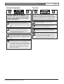
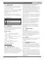
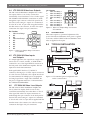
LTC 5231/90 & LTC 5234/90
Instruction Manual
EN Video Distribution
Amplifiers
(Indoor Use Only)
LTC 5231/90 & LTC 5234/90 | Instruction Manual | Important Safeguards
EN | 2
Important Safeguards
1. Read, Follow, and Retain Instructions - All safety
and operating instructions should be read and
followed before operating the unit. Retain instructions
for future reference.
2. Heed Warnings - Adhere to all warnings on the unit
and in the operating instructions.
3. Attachments - Attachments not recommended by the
product manufacturer should not be used, as they
may cause hazards.
4. Installation Cautions - Do not place this unit on an
unstable stand, tripod, bracket, or mount. The unit
may fall, causing serious injury to a person and
serious damage to the unit. Use only manufacturerrecommended accessories, or those sold with the
product. Mount the unit per the manufacturer's
instructions. Appliance and cart combination should
be moved with care. Quick stops, excessive force, or
uneven surfaces may cause the appliance and cart
combination to overturn.
5. Cleaning - Unplug the unit from the outlet before
cleaning. Follow any instructions provided with the
unit. Generally, using a damp cloth for cleaning is
sufficient. Do not use liquid cleaners or aerosol
cleaners.
6. Servicing - Do not attempt to service this unit
yourself. Opening or removing covers may expose
you to dangerous voltage or other hazards. Refer all
servicing to qualified service personnel.
7. Damage Requiring Service - Unplug the unit from
the main AC power source and refer servicing to
qualified service personnel under the following
conditions:
• When the power supply cord or plug is damaged.
• If liquid has been spilled or an object has fallen
into the unit.
• If the unit has been exposed to water and/or
inclement weather (rain, snow, etc.).
• If the unit does not operate normally, when
following the operating instructions. Adjust only
those controls specified in the operating
instructions. Improper adjustment of other controls
may result in damage, and require extensive work
by a qualified technician to restore the unit to
normal operation.
• If the unit has been dropped or the cabinet
damaged.
• If the unit exhibits a distinct change in
performance, this indicates that service is needed.
8. Replacement Parts - When replacement parts are
required, the service technician should use
replacement parts specified by the manufacturer or
that have the same characteristics as the original part.
Unauthorized substitutions may result in fire,
electrical shock or other hazards.
9. Safety Check - Upon completion of servicing or
repairs to the unit, ask the service technician to
perform safety checks to ensure proper operating
condition.
Bosch Security Systems | February 7, 2005
10. Power Sources - Operate the unit only from the type
of power source indicated on the label. If unsure of
the type of power supply to use, contact your dealer
or local power company.
• For units intended to operate from battery power,
refer to the operating instructions.
• For units intended to operate with External Power
Supplies, use only the recommended approved
power supplies.
• For units intended to operate with a limited power
source, this power source must comply with
EN60950. Substitutions may damage the unit or
cause fire or shock.
• For units intended to operate at 24VAC, normal
input voltage is 24VAC. Voltage applied to the
unit's power input should not exceed 30VAC.
User-supplied wiring, from the 24VAC supply to
unit, must be in compliance with electrical codes
(Class 2 power levels). Do not ground the 24VAC
supply at the terminals or at the unit's power
supply terminals.
11. Coax Grounding - If an outside cable system is
connected to the unit, ensure that the cable system is
grounded. U.S.A. models only - Section 810 of the
National Electrical Code, ANSI/NFPA No.70,
provides information regarding proper grounding of
the mount and supporting structure, grounding of the
coax to a discharge unit, size of grounding
conductors, location of discharge unit, connection to
grounding electrodes, and requirements for the
grounding electrode.
12. Grounding - This unit is equipped with a 3-wire
grounding plug (a plug with a third pin, for
grounding). This safety feature allows the plug to fit
into a grounding power outlet only. If unable to insert
the plug into the outlet, contact an electrician to
arrange replacement of the obsolete outlet. Do not
defeat the safety purpose of the grounding plug.
• Outdoor equipment should only be connected to
the unit's inputs after this unit has had its grounding
plug connected to a grounded outlet or its ground
terminal properly connected to a ground source.
• The unit's input connectors must be disconnected
from outdoor equipment before disconnecting the
grounding plug or grounding terminal.
• Proper safety precautions such as grounding should
be followed for any outdoor device connected to
this unit.
13. Lightning - For added protection during a lightning
storm, or when this unit is left unattended and unused
for long periods of time, unplug the unit from the
wall outlet and disconnect the cable system. This will
prevent damage to the unit due to lightning and
power line surges.
EN | 3
LTC 5231/90 & LTC 5234/90 | Instruction Manual | FCC Information
For Indoor Product
1. Water and Moisture - Do not use this unit near
water - for example, in a wet basement, in an
unprotected outdoor installation or in any area
classified as a wet location.
2. Object and Liquid Entry - Never push objects of
any kind into this unit through openings, as they
may touch dangerous voltage points or short out
parts that could result in a fire or electrical shock.
Never spill liquid of any kind on the unit.
3. Power Cord and Power Cord Protection - For
units intended to operate with 230VAC, 50Hz,
the input and output power cord must comply
with the latest versions of IEC Publication 227 or
IEC Publication 245.
Power supply cords should be routed so they are
not likely to be walked on or pinched. Pay
particular attention to location of cords and plugs,
convenience receptacles, and the point of exit
from the appliance.
4. Overloading - Do not overload outlets and
extension cords; this can result in a risk of fire or
electrical shock.
For Outdoor Product
Power Lines - An outdoor system should not be
located in the vicinity of overhead power lines,
electric lights or power circuits, or where it may
contact such power lines or circuits. When
installing an outdoor system, extreme care should
be taken to keep from touching power lines or
circuits, as this contact might be fatal. U.S.A.
models only - refer to the National Electrical
Code Article 820 regarding installation of CATV
systems.
For Rack-mount Product
1. Ventilation - This unit should not be placed in a
built-in installation or rack, unless proper
ventilation is provided, or the manufacturer’s
instructions have been adhered to. The
equipment must not exceed its maximum
operating temperature requirements.
2. Mechanical Loading - Mounting of the
equipment in a rack shall be such that a
hazardous condition is not achieved due to
uneven mechanical loading.
Bosch Security Systems | February 7, 2005
FCC & ICES INFORMATION
(U.S.A. and Canadian Models Only)
This device complies with part 15 of the FCC Rules. Operation is
subject to the following two conditions:
(1)
This device may not cause harmful interference, and
(2)
This device must accept any interference received,
including interference that may cause undesired
operation.
NOTE: This equipment has been tested and found to comply
with the limits for a Class B digital device, pursuant to Part 15 of
the FCC Rules and ICES-003 of Industry Canada. These limits
are designed to provide reasonable protection against harmful
interference when the equipment is operated in a residential
installation. This equipment generates, uses and can radiate radio
frequency energy, and if not installed and used in accordance
with the instructions, may cause harmful interference to radio
communications. However, there is no guarantee that interference
will not occur in a particular installation. If this equipment does
cause harmful interference to radio or television reception, which
can be determined by turning the equipment off and on, the user
is encouraged to try to correct the interference by one or
more of the following measures:
• Reorient or relocate the receiving antenna.
• Increase the separation between the equipment and receiver.
• Connect the equipment into an outlet on a circuit different
from that to which the receiver is connected.
• Consult the dealer, or an experienced radio/TV technician for
help.
Intentional or unintentional changes or modifications, not
expressly approved by the party responsible for compliance, shall
not be made. Any such changes or modifications could void the
user’s authority to operate the equipment.The user may find the
following booklet, prepared by the Federal Communications
Commission, helpful: How to Identify and Resolve Radio-TV
Interference Problems. This booklet is available from the U.S.
Government Printing Office, Washington, DC 20402, Stock No.
004-000-00345-4.
ATTENTION
OBSERVE PRECAUTIONS
FOR HANDLING
ELECTROSTATIC SENSITIVE
DEVICES
WARNING:
Electrostatic-sensitive device. Use
proper CMOS/MOSFET handling
precautions to avoid electrostatic
discharge.
NOTE: Grounded wrist straps must be worn and proper ESD
safety precautions observed when handling the electrostaticsensitive printed circuit boards.
This unit is to only be connected to
equipment compliant to the Safety Standard
for Information Technology Equipment (I.T.E.).
LTC 5231/90 & LTC 5234/90 | Instruction Manual | Safety Precautions
Safety Precautions
CAUTION: TO REDUCE THE RISK OF
ELECTRIC SHOCK, DO NOT REMOVE COVER
(OR BACK). NO USER SERVICEABLE PARTS
INSIDE. REFER SERVICING TO QUALIFIED
SERVICE PERSONNEL.
This symbol indicates the presence of
uninsulated “dangerous voltage” within the
product’s enclosure that can cause an electric
shock.
This symbol indicates the presence of
important operating and maintenance
(servicing) instructions in the literature
accompanying the appliance.
Installation should be performed by qualified
service personnel only in accordance with the
National Electrical Code or applicable local
codes.
Power Disconnect. Units with or without
ON-OFF switches have power supplied to the
unit whenever the power cord is inserted into the
power source; however, the unit is operational
only when the ON-OFF switch is in the ON
position. The power cord is the main power
disconnect for all units.
Bosch Security Systems | February 7, 2005
EN | 4
Sécurité
ATTENTION : POUR ÉVITER TOUT RISQUE D'ÉLECTROCUTION,
N'ESSAYEZ PAS DE RETIRER LE CAPOT (OU LE PANNEAU
ARRIÈRE). CET APPAREIL NE CONTIENT AUCUN COMPOSANT
SUSCEPTIBLE D'ÊTRE RÉPARÉ PAR L'UTILISATEUR. CONFIEZ
LA RÉPARATION DE L'APPAREIL À DU PERSONNEL QUALIFIÉ.
Ce symbole signale que le produit renferme une « tension
potentiellement dangereuse » non isolée susceptible de
provoquer une électrocution.
Ce symbole invite l'utilisateur à consulter les instructions
d'utilisation et d'entretien (dépannage) reprises dans la
documentation qui accompagne l'appareil.
Attention : l'installation doit exclusivement être réalisée par du
personnel qualifié, conformément au code national d'électricité
américain (NEC) ou au code d'électricité local en vigueur.
Coupure de l'alimentation. Qu'ils soient pourvus ou non d'un
commutateur ON/OFF, tous les appareils reçoivent de l'énergie une
fois le cordon branché sur la source d'alimentation. Toutefois,
l'appareil ne fonctionne réellement que lorsque
le commutateur est réglé sur ON. Le débranchement du cordon
d'alimentation permet de couper l'alimentation des appareils.
LTC 5231/90 & LTC 5234/90 | Instruction Manual | Contents
EN | 5
Table of Contents
Important Safeguards . . . . . . . . . . . . . . . . . . . . . . . . . . . . . . . . . . . . . . . . . . . . . . . . . . . . . . . . . . . . . . . . . .2
FCC Information . . . . . . . . . . . . . . . . . . . . . . . . . . . . . . . . . . . . . . . . . . . . . . . . . . . . . . . . . . . . . . . . . . . . .3
1.0
UNPACKING . . . . . . . . . . . . . . . . . . . . . . . . . . . . . . . . . . . . . . . . . . . . . . . . . . . . . . . . . . . . . . . . . .6
2.0
SERVICE . . . . . . . . . . . . . . . . . . . . . . . . . . . . . . . . . . . . . . . . . . . . . . . . . . . . . . . . . . . . . . . . . . . . .6
3.0
DESCRIPTION . . . . . . . . . . . . . . . . . . . . . . . . . . . . . . . . . . . . . . . . . . . . . . . . . . . . . . . . . . . . . . . .6
4.0
INSTALLATION . . . . . . . . . . . . . . . . . . . . . . . . . . . . . . . . . . . . . . . . . . . . . . . . . . . . . . . . . . . . . . .6
4.1
Power . . . . . . . . . . . . . . . . . . . . . . . . . . . . . . . . . . . . . . . . . . . . . . . . . . . . . . . . . . . . . . . . . . . . . . . . .6
4.2
Mounting . . . . . . . . . . . . . . . . . . . . . . . . . . . . . . . . . . . . . . . . . . . . . . . . . . . . . . . . . . . . . . . . . . . . . .6
4.3
LTC 5231/90 Video Inputs and Outputs . . . . . . . . . . . . . . . . . . . . . . . . . . . . . . . . . . . . . . . . . . . . . .6
4.4
LTC 5231/90 Video Loss Outputs . . . . . . . . . . . . . . . . . . . . . . . . . . . . . . . . . . . . . . . . . . . . . . . . . . .7
4.5
LTC 5234/90 Video Inputs and Outputs . . . . . . . . . . . . . . . . . . . . . . . . . . . . . . . . . . . . . . . . . . . . .7
4.6
LTC 5234/90 Video Loss Outputs . . . . . . . . . . . . . . . . . . . . . . . . . . . . . . . . . . . . . . . . . . . . . . . . . .7
5.0
OPERATION . . . . . . . . . . . . . . . . . . . . . . . . . . . . . . . . . . . . . . . . . . . . . . . . . . . . . . . . . . . . . . . . . .7
6.0
TYPICAL INSTALLATION . . . . . . . . . . . . . . . . . . . . . . . . . . . . . . . . . . . . . . . . . . . . . . . . . . . . . .7
Bosch Security Systems | February 7, 2005
EN | 6
LTC 5231/90 & LTC 5234/90 | Instruction Manual | Unpacking
1.0 UNPACKING
This equipment should be unpacked and handled with
care. If an item appears to have been damaged in
shipment, notify the shipper.
Verify that all parts shown in the Parts List have been
included. If any items are missing, notify your Bosch
Security Systems Sales or Customer Service
Representative.
The original packing carton is the safest container in
which to transport the unit. Save it for possible future use.
1.1
Parts List
Qty
Item
1
Unit (Verify Model Number)
2
AC Power Cords (one for 120 VAC, and one for
220 - 240 VAC)
1
9-Pin Cable Assembly
1
This Installation Manual
2.0
SERVICE
If the unit needs repair, contact the nearest Bosch
Security Systems Service Center for authorization to
return and shipping instructions.
The LTC 5231/90 and LTC 5234/90 also support
Bilinx technology, allowing bidirectional
communication through the video cable to access and
control Bilinx-enabled devices such as AutoDome and
Dinion cameras. A maximum of two (2) different types
of Bilinx controller models can communicate to a
common Bilinx-capable camera. Check with Bosch
Security Systems Sales Representative regarding future
product capabilities.
The LTC 5231/90 is a single-channel video distribution
amplifier with four (4) video outputs for distribution to
other video devices. A front panel LED indicates the
presence of video.
The LTC 5234/90 is a 4-channel video distribution
amplifier. It has four (4) independent distribution
amplifiers, each with one input and three outputs.
Front panel LEDs for each distribution amplifier
channel indicates the presence of video.
These are indoor products and supplied as desktop
units. Rack-mount kits are available from Bosch
Security Systems for mounting in a standard EIA
19-inch rack.
4.0
4.1
Service Centers
USA
Phone:
800-366-2283 or 717-735-6638
Fax:
800-366-1329 or 717-735-6639
CCTV Spare Parts
Phone:
800-894-5215 or 408-956-3853 or 3854
Fax:
408-957-3198
E-mail:
[email protected]
Canada
Phone:
514-738-2434
Europe, Middle East & Asia Pacific Region
Phone:
32-1-440-0711
For additional information, see
www.boschsecurity.com.
3.0
DESCRIPTION
The LTC 5231/90 and LTC 5234/90 are video
distribution amplifiers that provide multiple video
outputs identical to the video input signal. Their ample
bandwidth easily supports today's high-resolution video
signals. A video-loss-detection feature is available for
interfacing to external monitoring equipment.
Bosch Security Systems | February 7, 2005
INSTALLATION
Power
LTC 5231/90 and LTC 5234/90 models operate at
120/230 VAC, 50/60 Hz power. The model number is
shown on the label located on the bottom of the unit.
These units are supplied with grounded power cords;
grounding must not be defeated.
4.2
Mounting
These amplifiers are supplied as desktop units. For rack
mounting, the LTC 9101/00 Rack-mount Kit is
available.
4.3
LTC 5231/90 Video Inputs
and Outputs
In a simple application, the output from a single video
source such as a camera, switcher, or DVR/VCR is
connected to the signal INPUT connector on the back
panel of the distribution amplifier. The video input has
a fixed 75Ω termination.
The LTC 5231/90 has four (4) OUTPUT connectors,
allowing up to four video output connections at a time.
Devices connected to the outputs must be set for 75Ω
termination. If multiple pieces of equipment are being
looped from a single video OUTPUT, the last piece of
equipment must have a 75Ω termination. See TYPICAL
INSTALLATION.
EN | 7
LTC 5231/90 & LTC 5234/90 | Instruction Manual | Installation
4.4
LTC 5231/90 Video Loss Outputs
The LTC 5231/90 Distribution Amplifier has a video
loss output, which is a set of relay contacts that
automatically close when there is a loss of video signal.
The VIDEO LOSS OUTPUT connections are made
through the 9-pin connector on the back panel of the
unit. The contact rating is 1 ampere at a maximum of
40 volts AC or DC. A 9-pin cable is supplied with the
unit that mates to the connector, for video loss output
connections. See Figure 1 for pin connections.
Pin Function
1
Video Loss Relay 1
2
NC
1 4 7
3
NC
4
Video Loss Relay 1
2 5 8
5
NC
6
NC
3 6 9
7
NC
8
NC
9
NC
Figure 1: Video Loss Output Relay Connections
LTC 5231/90
Pin Function
1
Video Loss Relay 1
2
Video Loss Relay 2
1 4 7
3
Video Loss Relay 2
4
Video Loss Relay 1
2 5 8
5
NC
6
Video Loss Relay 3
3 6 9
7
Video Loss Relay 4
8
Video Loss Relay 4
9
Video Loss Relay 3
Figure 2: Video Loss Output Relay Connections
LTC 5234/90
5.0
OPERATION
These units require no operational adjustments. The
power ON indicator illuminates when power is applied
to the unit, and the VIDEO indicators illuminate when
video is supplied to the inputs.
6.0
TYPICAL INSTALLATION
Video & Data
75Ω
Hi-Z
Control
Data
(LOOPING
CONFIGURATION)
Bilinx-enabled
AutoDomes
Video
4.5
LTC 5234/90 Video Inputs
and Outputs
VIDEO LOSS OUTPUT
O
U
T
P
U
T
S
In a simple application, the output from a single video
source such as a camera, switcher, or DVR/VCR is
connected to one of four signal INPUT connectors on
the back panel of the distribution amplifier. The four
inputs have fixed 75Ω terminations.
Each signal INPUT has three (3) OUTPUT
connectors, allowing up to 12 video output connections
at a time. Devices connected to the outputs must be set
for 75Ω termination. If multiple pieces of equipment
are being looped from a single video OUTPUT, the
last piece of equipment must have a 75Ω termination.
See TYPICAL INSTALLATION.
INPUT
Bilinx
Communication
75Ω
Divar
LTC 8016/90
Bilinx-enabled
DVR
Allegiant Bilinx
Data Interface
BOSCH
Prod
Mon
Shot
Clr
BOSCH
1
2
3
4
5
6
7
8
9
Prod
2
3
5
6
7
8
9
Keyboard
Figure 3: LTC 5231/90 Typical Configuration with
Bilinx Communication
75Ω
(LOOPING
CONFIGURATION)
VIDEO LOSS OUTPUT
O
U
T
P INPUT 2
U
T
S
INPUT 1
75Ω
O
U
T
P INPUT 3
U
T
S
O
U
T
P
U
T
S
O
U
T
P INPUT 4
U
T
S
75Ω
CH4
CH3
ALARM
SYSTEM
Figure 4: LTC 5234/90 Typical Configuration
Bosch Security Systems | February 7, 2005
Shot
1
4
0
Keyboard
LTC 5234/90 Video Loss Outputs
The LTC 5234/90 Video Distribution Amplifier has
four (4) video loss outputs, which are sets of relay
contacts that automatically close when there is a loss of
video signal. The video loss output connections are
made through the 9-pin connector on the back panel of
the unit. The contact rating is 1 ampere at a maximum
of 40 volts AC or DC. A 9-pin cable is supplied with the
unit that mates to the connector, for video loss output
connections. See Figure 2 for pin connections.
Mon
Clr
0
Hi-Z
4.6
Allegiant
Matrix System
Americas
Bosch Security Systems
130 Perinton Parkway
Fairport, New York, 14450, USA
Phone: +1 (585) 223 4060
Fax:
+1 (585) 223 9180
E-mail: [email protected]
www.boschsecurity.us
Europe, Middle East, Africa
Bosch Security Systems B.V.
P.O. Box 80002
5600 JB Eindhoven, The Netherlands
E-mail:
[email protected]
http://www.boschsecurity.com
Asia-Pacific
Bosch Security Systems Pte Ltd
38C Jalan Pemimpin
Singapore 577180, Singapore
Phone: +65 319 3488
Fax:
+65 319 3499
E-mail:
[email protected]
http://www.boschsecurity.com
© 2005 Bosch Security Systems GmbH
3935 890 49712 05-06 | Updated February 7, 2005 | Data subject to change without notice.
Bilinx, AutoDome, and Dinion are registered by Bosch Security Systems, Inc. in the US Patent Trademark Office.