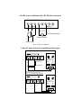
1
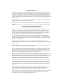
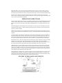
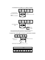
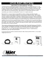
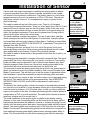
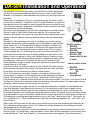
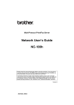
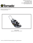
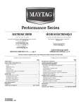
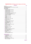
VEHICLE DETECTION AT ITS BEST!!!
To download a full-color manual, or for information on our other products, please visit:
www.mierproducts.com
2011
DA-500 BURIED SENSOR SYSTEM
INSTALLATION AND OPERATION MANUAL
www.mierproducts.com
Wireless Vehicle Detection * Driveway Alarms * Drive-Up Window Detection * Buried Sensor Systems * Instrument Boxes * DVR Lockboxes Rack-Mount
Lockboxes * CPU/DVR Tower Lockboxes * Flush-Mount Cabinets * Outdoor Enclosures * Temperature Controlled Enclosures Power Supply Boxes
Siren/Speaker Cabinets * Bell Boxes * Battery Cabinets * Transformer Enclosures * Custom Enclosures & Fabrication
Model DA-500 Installation & Operations Manual
General Information
Drive-Alerts are perfect for use in residential
driveways, on farms, at drive-up windows, in
remote locations, and to protect valuable
equipment such as tractors or constuction
vehicles. The Drive-Alert will detect a vehicle
approaching, or whenever a vehicle or metal
equipment is moved.
The Drive-Alert detects any metal which
contains iron. It will not detect copper or
aluminum.
The Drive-Alert’s method of operation is to
sense the change in the magnetic field around
it. This field is always present, and is disrupted
when a metal object moves through it. The key
element in the Drive-Alert installation is to
locate the sensor/probe in the area where you
wish to detect this change. The usual
installation is near the entrance of a driveway,
but located far enough away from roads or
streets so as not to detect traffic.
Moving ferrous (iron) metal trips the sensor.
Larger metal objects are detected easier than
smaller. Faster moving metal objects are
detected easier than slower. Metal moving
nearer the probe is detected easier than metal
moving farther away. These are the three factors
which determine the system’s range of
detection. Therefore, trucks traveling 65 mph
can be detected up to 50 feet; cars moving
4 mph up to 8 feet; and a walking person with
steel toe shoes up to 1 foot.
The Master Control Panel houses the
electronics which allows the Drive-Alert to
function. It also contains a noisemaker, and
the terminal strip permits the attachment of the
probe as well as remote noisemakers or other
devices.
A Timer Control unit is available. It is housed
in a separate box and is attached by wires to the
terminal strip on the Master Control Panel.
The Timer Control turns on of lights, usually
outside lights, for an adjustable period when a
vehicle is detected.
DA-500 Complete
includes a Master Control Panel,
Sensor, and 100’ of direct
burial cable
DA-655 Chime with Volume
DA-505 Timer Control
DA-052 Remote Whistle
INSTALLATION
The Master Control Panel is generally located in a closet, utility room, or garage. If the only noisemaker
used (remotes are available) is the one contained within the control panel, the panel must be located
where users can easily hear the “whistle.” The control panel is not suitable for outdoor installation. Also,
120 volt AC power must be available. The ease of routing the three-wire cable from the sensing probe
should be considered when deciding the location of the panel. The control panel is usually attached to the
wall with screws.
Improper installation is the No. 1 reason for system malfunction. Please use caution when installing the
sensing probe to assure a properly operating Drive-Alert.
The probe’s sensor is a coil of wire wrapped around an iron rod. Its resistance is 900-1100 ohms. The red
and black wires connect to the coil. It is encapsulated in epoxy to protect it from physical damage and
moisture.
DO NOT CUT OR NICK THE CABLE JACKET!
If moisture enters, false alarms will be the result!
The cable is made with an extra thick outer cover. There is a foil wrapper surrounding the red and black
wires. There is a silver (bare) wire in the foil. False alarms will occur if moisture gets into the foil
wrapper. Nicks in the outer cover and improper splices allow moisture to enter the cable. As moisture
enters the cable, the resistance decreases. Resistance between the red or black wire to the shield wire
must be infinite. (Use meter with ability to read resistance above 20 million ohms).
The ideal installation is without any splices. The use of cable other than that which is designed for the
Drive-Alert is undesirable. Improper splices and unsuitable cable are major causes of false alarms. If
splicing is unavoidable, splice the cable using a 3M SLiC-TM SPLICE KIT, or equivalent. The splice kit
is available from Mier Products.
The sensing probe does not know if it is in or out of the ground, but it must remain absolutely
motionless. Most probes are buried 6 inches deep and parallel to the driveway. Be sure to protect it from
physical damage.
The cable is made for direct burial in the ground. Do whatever is necessary to protect it from physical
damage to the outer cover, such as using 1/2-inch PVC pipe.
The probe responds to changes in the magnetic field around it. The signal produced by the coil is a few
micro volts for a fraction of a second. The probe and cable must not be within 3 feet of electric wires
because they have changing magnetic fields of their own. Never bury the cable in the same trench with
other electrical wires, including telephone wires and wires for lights, bells, etc.
You may wish to place a sensing probe atop the ground in the general area of where you wish to bury it,
and connect the cable to the control panel. This will allow you to TEST the system in application
BEFORE final installation. It would be acceptable to leave the sensing probe and cable above the ground
for a couple of days, but make certain it is not damaged during this period. This method should not be
used permanently. See OPERATIONS INSTRUCTIONS for adjustments which may be necessary.
The burial of the probe is ideal in the center of the area being monitored, but often is not practical. If a
new driveway is being put in, the sensing probe could be buried a minimum of 12-24 inches deep. In
case you wish to place the sensor in the center of the drive, the cable and sensing probe could be placed
in a larger piece of PVC to provide protection. The cable should also be protected whenever vehicles
move over it.
The usual installation of the sensing probe is parallel to an already existing driveway. In this case, the
probe can be buried 6 inches deep, and the cable simply placed below the grass line. However, if
vehicles are going to travel directly over the probe and cable, they should be buried deeper.
The sensing probe may be placed up to 5,000 feet from the Master Control Panel. Up to 4 sensing probes
can be attached to one panel, but each additional probe reduces every probe’s ability to detect. The
Drive-Alert will not know which sensing probe detects a vehicle.
When more than 1 probe is used, connect the red and black wires in series. Connect the silver wires in
parallel. The red wire from one cable is soldered to a black wire from another cable. The remaining red
wire & black wire are attached to the Drive-Alert terminals. All silver wires are attached to the Drive-Alert.
Keep the probe, cable, and control panel at least 8 feet away from heavy power lines, power panels,
motors, arcing or sparking machinery, and radio transmitters. In some cases, moving the panel and/or cable
a few feet can solve interference problems.
OPERATION INSTRUCTIONS
The Drive-Alert is adjusted at the factory for maximum sensitivity for the probe and minimum time for the
whistle. To adjust these, open the control panel and adjust the small pots according to the diagram on the
inside cover (see below). The whistle “timer adjust” is adjustable from 1-12 seconds and the LED 3 will
light.
When first plugged in, the red blanker LED 2 will remain on for only 1 minute, and the Drive-Alert will
be muted for approximately 1 minute each time the electrical power is turned on. It provides time for the
electronic circuits to stabilize.
During normal operation, the noise blanker detects unwanted electrical interference and mutes the DriveAlert for a few seconds. It has been adjusted at the factory. The blanker light should be off during normal
operation.
To test the Master Control Panel, it is possible to rub your finger simultaneously on the three terminals to
which the sensing probe is attached. This should cause the system to go into false alarm. This will occur
with or without the sensing probe attached. Be sure the terminal screws are tight while making the test. If
the system responds to this test, in almost all instances it indicates a properly functioning control panel.
If false alarms occur, remove the sensing probe wires fron the Drive-Alert terminals. Let the power remain
turned on to the control panel. If the false alarm stops, then the most likely cause of the problem is
moisture in the sensing probe cable. Radio transmitters, cell phones, and cordless phones within 10 feet of
the control panel may cause false alarms. Please call for special filter instructions in these cases.
Additional devices can be attached to the Drive-Alert on its terminals at the bottom of the control panel.
When the whistle switch is turned off, the Drive-Alert terminals can switch customer provided electrical
current up to 5 AMPS. Never attach any device that puts more than 30 volts on the Drive-Alert terminals.
When the whistle switch is turned on, the Drive-Alert terminals have available 24 VDC at 100 MA. Refer
to the diagrams in this manual for hookup instructions.
Mier Products has available a Timer Control that attaches to the Drive-Alert terminals. The Timer Control
is adjustable from 45 seconds to 45 minutes. It switches up to one thousand watts of 115 volt power for
outside lights. Mier Products also has available remote chimes (the DA-655 is the most popular accessory
and perfect for drive-up window applications), whistles, and other devices.
MASTER CONTROL PANEL ADJUSTMENTS
BLANKER ADJUST
BLANKER
LED 2
MAX
MIN
TIMER ADJUST
1 AMP FUSE
LED 3 ALARM
MIN
MAX
SENSITIVITY
MAXIMUM CONTACT CURRENT IS 100 MILLIAMP AT
24 V WHEN USING DRIVE-ALERT VOLTAGE SUPPLY
SENSOR
RELAY
DO NOT CONNECT TO 120V AC
RELAY
POWER
LED 1
CONTROLLING EXTERNAL ALARMS & CHIMES
NEG
4
+24V
5
NO
6
NC
7
External 24VDC Bell
DA-500 Whistle Switch ON
C
8
Capacitor
0.1 Microfarads 100 Volt (min)
NOTE:
Limit of two external bells
BELL
NEG
4
+24V
NO
NC
C
5
6
7
8
External Relay Hookup
24VDC
1N4004 DIODE
To AC operated
CHIMES/ALARMS
RELAY
NOTE: If internal piezo whistle is not wanted, move the DA-500 Whistle Switch to
the OFF position and connect the jumper between +24 and the C Terminal
CONNECTION USING DRY CONTACTS & EXTERNAL POWER
NEG
4
+24V
5
NO
6
NC
7
C
8
Capacitor
0.1 Microfarads 100 Volt (min)
DA-500 Whistle Switch
MUST be OFF
BELL
External Power
Maximum current linited to 1 AMPERE
Maximum Voltage - 24 VOLTS (DO NOT apply 120VAC to terminals)
RED BLK SHLD NEG +24V NO
UNREG
--- SENSOR ---
1
2
3
4
NC
C
--- RELAY ---
5
6
DO NOT CONNECT TO 120V AC
7
8
DA-500 Sensor and Remote DA-052 Whistle Connection
RED BLK SHLD NEG +24 NO NC
1
2
3
4
5
- SENSOR -
6
C
7
8
-- RELAY -DA-052
DA-500 Whistle ON
Remote Whistle
Sensor Cable
Note: Limit of 10 Whistles
Using AC house wiring for transmitting alarm signal
Method A (with DA-500 Whistle ON)
using a DA-058 Chime
NEG
4
+24V
NO
5
6
1
NC
C
7
8
RELAY
UNIT
B
HOUSE
DA-057
Powerflash Interface
560 OHM Resistor
1500 OHM Resistor
INPUT
A B
INPUT
1 2 3
+
-
C
Both the DA-057 Transmitter AND the DA-058 Chime plug into an AC outlet.
Set BOTH to the same unit and house code.
NOTE: INPUT AND MODE SWITCH SETTINGS
Method B (with DA-500 Whistle OFF)
using a DA-058 Chime
NEG
4
+24V
5
NO
6
NC
7
RELAY
1
C
8
UNIT
B
HOUSE
DA-057
Powerflash Interface
INPUT
A B
-
INPUT
1 2 3
+
Model DA-500 Drive-Alert Contents
•
•
•
•
•
•
•
Solid-state Master Control Panel
Electronic whistle with “on-off” switch
Red LED power-on indicator
UL listed transformer and cord
100 feet of two-conductor shielded direct burial cable; other lengths available
Weatherproof sensor
SPDT relay output available
Specifications
•
•
•
•
•
•
•
•
Input -- 120 VAC, 50-60Hz, 3.6 Watts
Output -- 24 VDC at 100 Milliamps
Surge protected from transients
Adjustable sensor sensitivity
Adjustable time control for electronic whistle
Operating temperature -- 20 degree F to 160 degree F
Provisions for activating optional timer control
Weight -- six (6) pounds
Mier Products’ Limited Warranty Program
The Mier Products’ Limited Warranty Program covers only the Drive-Alert -- for original owner
only -- for one year from date of purchase against defects in original parts or workmanship. It
agrees to repair or replace such defects (Mier Products’ option) -- without charge for parts or
labor -- if the defective unit is returned prepaid to Mier Products, Inc., Kokomo, IN, 46901,
within the first year. Sensor probe and cable that have been buried are not covered.
Responsibility is not assumed for damage due to accident, faulty wiring, overload of Drive-Alert
output, or installation other than that recommended by Mier Products, Inc. Repair work not
covered by the Warranty will be made at a nominal charge. When returning a unit for any reason,
please include a note describing the problem. Also include your name, address and telephone
number.
For Technical Assistance please call 1-800-473-0213
1500 North Ann Street, Kokomo, IN, 46901
www.mierproducts.com
[email protected]
800-473-0213
DA-655
Drive-Alert Chime with volume control
DA-655
Residential Driveway Application
• The DA-655 is the perfect accessory for the original DA-500
and the new DA-600 wireless Drive-Alerts when a more
pleasant tone and/or volume control is desired.
• Perfect for drive-up windows and high traff c areas
• The DA-655 Chime replaces the whistle within the DriveAlert, and emits a pleasant chime whenever a vehicle is
detected.
• Volume can be adjusted from silent to a very loud setting
• Easy to install
• Connecting cables included
Call us! We’ll be happy to help with any technical or
installation questions...and don’t forget to check out our
website for more products!
DA-600
DA-500
Drive-Up Window Application
Wireless DA-600 Complete
Drive-Alert Driveway Alarm
System is pictured above for
reference.
Original DA-500 Complete
Drive-Alert Driveway Alarm
System is pictured above for
reference.
www.mierproducts.com
Wireless Vehicle Detection * Driveway Alarms * Drive-Up Window Detection * Buried Sensor Systems * Instrument Boxes * DVR & CPU
Lockboxes * Flush-Mount Cabinets * Outdoor Enclosures * Temperature Controlled Enclosures * Power Supply Boxes * Siren/Speaker Cabinets
Bell Boxes * Battery Cabinets * Transformer Enclosures * Custom Enclosures and Fabrication
4
Installation of Sensor
Caution and care must be exercised in installing the sensing probe to assure
a properly operating Drive-Alert System. Improper installation is the number
one reason for the systems to malfunction. The probe’s sensor is a coil of wire
wrapped around an iron rod. Its resistance is 700 to 1200 ohms. The red and
black wires connect to the coil. It is encapsulated in epoxy to protect it from
physical damage.
The cable is made with an extra thick outer cover. There is a foil wrapper
surrounding the red and black wires. There is a silver (bare) wire in the foil. False
alarms will occur if moisture gets into the foil wrapper. Nicks in the outer cover
and improper splices allow moisture to enter the cable. As moisture enters the
cable, the resistance decreases. There must be greater than 20 meg (million)
ohms from the silver wire to the colored wires.
The ideal installation is without any splices. The use of cable other than that,
which is designed for the Drive-Alert System, is undesirable. Improper splices
and unsuitable cable are major causes of false alarms. If splicing is unavoidable,
splice the cable using a 3M SLIC-3M SPLICE KIT, or equivalent. The splice kit is
available from Mier Products.
The sensing probe does not know if it is in or out of the ground, but it must
remain absolutely motionless. Most sensing probes are buried about 6 inches
deep and parallel to the driveway. Protect it from physical damage.
The cable is made for direct burial in the ground but make sure not to nick or cut
the outer cover.
The sensing probe responds to changes in the earth’s magnetic field. The signal
produced by the coil is a few microvolts for a fraction of a second. The sensing
probe and cable must not be within 3 feet of electric wires because they have
changing magnetic fields of their own. Never bury sensing probe cable in the
same trench with other electrical wires and wires for lights, bells, etc.
You may wish to place the sensing probe atop the ground in the general area of
where you believe it would be an ideal installation, and connect the cable to the
Master Control panel. This will allow you to test the system in application before
final installation. It would be acceptable to leave the sensing probe and cable
above the ground for a couple of days, but make certain it is not damaged during
this period. This method should not be used permanently. See OPERATION
INSTRUCTIONS of DA-503 and DA-504 for adjustments, which may be
necessary.
The burial of the sensing probe is ideal in the center of the area being detected,
but often this is not practical. If a new driveway is being put in, the sensing probe
could be buried a minimum of 12-24 inches deep. In case you wish to place the
sensor in the center of the drive, the cable and sensing probe could be placed in
a larger piece of PVC to provide protection. The cable should also be protected
whenever vehicles are to be moved over it.
The usual installation of the sensing probe is parallel to an already existing
driveway. In this case, the sensing probe can be buried 6 inches deep, and the
cable simply placed below the grassline. However, if vehicles are going to travel
directly over the sensing probe and cable, the probe and cable should be buried
deeper. The sensing probe may be placed up to 5,000 feet from the solid-state
Master Control panel. Several sensing probes can be attached to one panel, but
each additional sensing probe slightly reduces every sensing probe’s ability to
detect. The Drive-Alert will not know which sensing probe does the detecting.
The sensing probe is a
1” x 12” cylinder
containing a sealed
sensor. Be cautious
when handling the
sensor and particularly
careful to not nick the
cable attached to it.
Bury probe at least 6” deep
10’
A typical installation is
the probe 6 inches deep
parallel to drive.
10’
10’
To extend your detection
range install sensor in the
center of drive.
RED BLK SHLD NEG +24V NO
UNREG
--- SENSOR ---
1
2
NC
--- RELAY
3
4
5
6
7
C
--8
DO NOT CONNECT TO 120V AC
Red
Black
Shield
Connect the sensor’s red,
black and shield wires to
the clearly marked
terminals in the control
panel.
Sensor Installation continued
5
Probe & Cable
Illustration
When more than one sensing probe is used, connect the red and black wires in series. Connect the
silver wires in parallel. The red wire from one cable is soldered to a black wire from another cable. The
remaining red wire and black wire are attached to the Drive-Alert terminals. All silver wires are attached
to the Drive-Alert terminals.
Keep the sensing probe, the cable and the solid state control panel at least 8 feet from heavy power
lines, power panels, motors, arcing or sparking machinery, and radio transmitters. In some cases, moving the panel and/or cable a few feet can solve interference problems.
1-800-473-0213 | www.mierproducts.com
Buried Sensor Vehicle Detection Systems
For more information on these units, our wireless Drive-Alerts,
or our other products please visit
www.mierproducts.com
2010
DA-503 and DA-504
BURIED SENSOR DRIVE-ALERT
INSTALLATION AND OPERATION MANUAL
1-800-473-0213 | www.mierproducts.com
Wireless Vehicle Detection | Driveway Alarms | Drive-Up Window Detection | Buried Sensor Systems | Instrument Boxes
DVR/CPU Lockboxes | Flush-Mount Cabinets | Outdoor Enclosures | NEMA 4 Enclosures | Temperature Controlled Enclosures
Power Supply Boxes | Siren/Speaker Cabinets | Bell Boxes | Battery Cabinets | Transformer Enclosures | Custom Fabrication
Introduction
2
The installation of an alarm system that sounds an alert of an approaching vehicle has become easier
with the DA-503 and DA-504 Drive-Alert Warning Systems. The DA-503 and DA-504 expand the DriveAlert’s usefulness by transmitting the alarm throughout a building without using wired connections. A
building’s electrical wiring is used to carry the signal where desired.
The DA-503 utilizes pleasant chimes to let you know of a vehicle’s approach. The DA-504 expands this
feature by including a timer feature to illuminate vehicle entrance areas for selected times using remotely
controlled lamps. The Drive-Alert’s most popular use is in driveway applications. A probe senses the
earth’s magnetic field and when a passing vehicle disturbs that field, an alarm is
generated and transmitted to alert you of the vehicle’s presence.
Locating the sensor probe adjacent to a driveway but away from street traffic allows the detection and
warning of a vehicle entering a selected area. Fast moving vehicles, particularly trucks, along a street can
be detected up to 50 feet from the sensor. Slow, moving cars traveling at 5 miles an hour can be detected
8 feet away, and a person walking with steel toed shoes up to 1 foot away also can be detected. Thus, a
probe location should be chosen with the above in mind. The Master Control contains the detection and
signaling electronics that sends the alarm to all parts of a building.
SPECIFICATIONS
Input - 120 VAC, 50-60 HZ, 3.6 Watts
Output - Power line carrier signaling
Auxiliary Output - 24 VDC at 100 Milliamps
Adjustable sensor sensitivity
Operating temperature is -30 degrees F to 120
degrees F
Weight - 6 pounds
Table of Contents
INTRODUCTION
DRIVE-ALERT WARRANTY
INSTALLATION OF SENSOR
INSTALLATION OF DA-503
INSTALLATION OF DA-504
ACCESSORIES
TROUBLE-SHOOTING HINTS
EXPLANATION OF LEDS
Page 2
Page 3
Page 4-5
Page 6
Page 7-8
Page 8
Page 9
Page 10
1-800-473-0213 | www.mierproducts.com
Drive-Alert Warranty
3
MIER PRODUCTS LIMITED WARRANTY PROGRAM
The Mier Products Limited Warranty program covers the Drive-Alert - for original owner only - for one
year from date of purchase against defects in original parts or workmanship. Mier Products, Inc. agrees
to repair or replace parts (Mier’s option) that are deemed defective by our Quality Control Team, without charge for parts or labor, if the defective unit is returned prepaid to Mier Products, Inc., Kokomo, IN,
46901, within the one-year warranty period. Mier Products, Inc. recommends inspection of parts
immediately upon receipt and contacting Mier Products, Inc. if quality issues arise.
Mier Products, Inc. does not assume responsibility for claims or damages caused by improper
installation or use of these products, accessories, and/or products connected to them. Mier Products,
Inc. does not assume responsibility for damages to these products or their accessories due to shipping
damage or damage occurring while in a customer’s warehouse and/or possession. These products and
any accessories must be shipped, handled, stored, and installed with strict adherence to our instructions.
Responsibility is not assumed for damage due to accident, faulty wiring, overload of Drive-Alert output, or
installation other than that recommended by Mier Products, Inc. Repair work not covered by the Warranty
will be made at a nominal charge. When returning a unit for any reason, please include a note describing
the problem. Also include your name, address, and telephone number. Sensor probe and cable that have
been buried are not covered by warranty.
This warranty constitutes the entire warranty with respect to Mier’s Drive-Alert Systems and IS IN LIEU
OF ALL OTHERS, EXPRESSED OR IMPLIED, INCLUDING ANY WARRANTY OR MERCHANTABILITY
AND WARRANTY OF FITNESS FOR A PARTICULAR PURPOSE AND IN NO EVENT IS MIER
PRODUCTS, INC., OR IT’S OEM PARTNERS, RESPONSIBLE FOR ANY CONSEQUENTIAL
DAMAGES OF ANY NATURE WHATSOEVER.
Any warranty OR sales questions should be directed to Mier Products at 800-473-0213, or via e-mail to
[email protected]
1-800-473-0213 | www.mierproducts.com
4
Installation of Sensor
Caution and care must be exercised in installing the sensing probe to assure
a properly operating Drive-Alert System. Improper installation is the number
one reason for the systems to malfunction. The probe’s sensor is a coil of wire
wrapped around an iron rod. Its resistance is 700 to 1200 ohms. The red and
black wires connect to the coil. It is encapsulated in epoxy to protect it from
physical damage.
The cable is made with an extra thick outer cover. There is a foil wrapper
surrounding the red and black wires. There is a silver (bare) wire in the foil. False
alarms will occur if moisture gets into the foil wrapper. Nicks in the outer cover
and improper splices allow moisture to enter the cable. As moisture enters the
cable, the resistance decreases. There must be greater than 20 meg (million)
ohms from the silver wire to the colored wires.
The ideal installation is without any splices. The use of cable other than that,
which is designed for the Drive-Alert System, is undesirable. Improper splices
and unsuitable cable are major causes of false alarms. If splicing is unavoidable,
splice the cable using a 3M SLIC-3M SPLICE KIT, or equivalent. The splice kit is
available from Mier Products.
The sensing probe does not know if it is in or out of the ground, but it must
remain absolutely motionless. Most sensing probes are buried about 6 inches
deep and parallel to the driveway. Protect it from physical damage.
The cable is made for direct burial in the ground but make sure not to nick or cut
the outer cover.
The sensing probe responds to changes in the earth’s magnetic field. The signal
produced by the coil is a few microvolts for a fraction of a second. The sensing
probe and cable must not be within 3 feet of electric wires because they have
changing magnetic fields of their own. Never bury sensing probe cable in the
same trench with other electrical wires and wires for lights, bells, etc.
You may wish to place the sensing probe atop the ground in the general area of
where you believe it would be an ideal installation, and connect the cable to the
Master Control panel. This will allow you to test the system in application before
final installation. It would be acceptable to leave the sensing probe and cable
above the ground for a couple of days, but make certain it is not damaged during
this period. This method should not be used permanently. See OPERATION
INSTRUCTIONS of DA-503 and DA-504 for adjustments, which may be
necessary.
The burial of the sensing probe is ideal in the center of the area being detected,
but often this is not practical. If a new driveway is being put in, the sensing probe
could be buried a minimum of 12-24 inches deep. In case you wish to place the
sensor in the center of the drive, the cable and sensing probe could be placed in
a larger piece of PVC to provide protection. The cable should also be protected
whenever vehicles are to be moved over it.
The usual installation of the sensing probe is parallel to an already existing
driveway. In this case, the sensing probe can be buried 6 inches deep, and the
cable simply placed below the grassline. However, if vehicles are going to travel
directly over the sensing probe and cable, the probe and cable should be buried
deeper. The sensing probe may be placed up to 5,000 feet from the solid-state
Master Control panel. Several sensing probes can be attached to one panel, but
each additional sensing probe slightly reduces every sensing probe’s ability to
detect. The Drive-Alert will not know which sensing probe does the detecting.
The sensing probe is a
1” x 12” cylinder
containing a sealed
sensor. Be cautious
when handling the
sensor and particularly
careful to not nick the
cable attached to it.
Bury probe at least 6” deep
10’
A typical installation is
the probe 6 inches deep
parallel to drive.
10’
10’
To extend your detection
range install sensor in the
center of drive.
RED BLK SHLD NEG +24V NO
UNREG
--- SENSOR ---
1
2
NC
--- RELAY
3
4
5
6
7
C
--8
DO NOT CONNECT TO 120V AC
Red
Black
Shield
Connect the sensor’s red,
black and shield wires to
the clearly marked
terminals in the control
panel.
Sensor Installation continued
5
Probe & Cable
Illustration
When more than one sensing probe is used, connect the red and black wires in series. Connect the
silver wires in parallel. The red wire from one cable is soldered to a black wire from another cable. The
remaining red wire and black wire are attached to the Drive-Alert terminals. All silver wires are attached
to the Drive-Alert terminals.
Keep the sensing probe, the cable and the solid state control panel at least 8 feet from heavy power
lines, power panels, motors, arcing or sparking machinery, and radio transmitters. In some cases, moving the panel and/or cable a few feet can solve interference problems.
1-800-473-0213 | www.mierproducts.com
6
DA-503 Installation and Operation
The standard components that make up the DA-503 Drive-Alert are pictured.
You may have purchased additional Remote Chimes, or the length of cable
attached to the sensor may be longer than that illustrated. Please refer to
Installation of Sensor for details on that portion of the installation. The Master
Control may be attached to any wall with consideration given to the ability to
easily connect the sensor wire and to have 120-volt power available.
Installation of the Master Control should not be made near telephones or radio
transmitters. The alarm signal generated by the DA-503 is transmitted to
remotely located Chimes through the 120-volt power lines located in the
building. The power line carrier units transmit and receive coded signals to
activate selected receiving modules that provide the desired alarm signals.
The ability to utilize existing power lines in a building (your house’s wiring)
eliminates the need for running separate wires to the chimes.
In this model, a single X-10 Powerhouse Powerflash Interface, installed in the
Master Control, sends the coded signal to the Remote Chimes via the power
line wires.
Remote Chimes may be installed in any 120-volt outlet in a home, garage,
barn, or outbuilding as long as it is on the same public utility transformer servicing the home. A typical installation is the location of the Master Control in a
garage or utility room. Multiple Remote Chimes may be used, and generally
are located in basements, family rooms, and bedrooms - wherever it is desirable for the sound to be heard.
Unique house and unit codes are utilized to direct the DA-503 alarm signal to
these receivers throughout the building. The house and unit codes are preset
at the factory for the transmitter and chime. The X-10 Powerflash transmitter
installed in the Drive-Alert Control Panel, which controls the Remote Chimes,
is set on Unit Code 1 and House Code B (Input set on A and Mode on 3).
Remote Chimes should be set on the same codes - Unit Code 1 and House
Code B.
The X-10 Remote Chime will sound three notes once during any transmitted
alarm. The alarm signal must go off and turn back on before another chime
cycle can occur.
Other house and unit codes can be used as long as both the receiver and
transmitter are identically set. Such changes would be made if other X-10
Controls are utilized elsewhere in the building and cause interference with the
DA-503 alarms.
The DA-503 has been adjusted for maximum sensitivity for the sensing probe
and minimum time for the Remote Chime. To change these, open the
Master Control, and find the components on the printed circuit board identified
as “Time” and “Sensitivity,” which are pictured on the diagram.
Follow the increase or decrease arrows to make adjustments. Use a small
screwdriver and use only light pressure to obtain the desired settings.
The red light on the LED 2 circuit board will remain on for one minute as a
warm-up period when the DA-503 first receives power. The function of this
circuit is to detect unwanted electrical interference during normal operation.
It has been adjusted during testing, but if changes are desired, adjust the pot
with a small screwdriver. Turn the pot clockwise until the red light turns on.
Then turn the pot counterclockwise until the red light turns off. Continue
turning the pot a small amount beyond that point.
DA-503 includes:
• DA-503
Control Panel
• DA-058
Remote Chime
• DA-051-100
Sensor with 100 feet
of cable
Master Control Panel
Adjustments
Blanker Adjust
1 Amp
Fuse
Blanker
LED 2
Min
Max
Timer Adjust
Min
Max
Alarm
LED 3
Sensitivity
Maximum Contact Currents Is 100 Milliamp at
24V When Using Drive-Alert Voltage Supply
Sensor
Relay
Do Not Connect to 120V AC
Relay
Power
LED 1
POWER LED 1 on at all times.
BLANKER ADJUST set at factory.
LED 2 on for one minute when
powered up; out at all
other times.
LED 3 indicates alarm.
7
DA-504 Installation and Operation
The standard components that make up the DA-504 Drive-Alert are pictured.
You may have purchased additional Remote Chimes, Lamp or Light Switch
Modules, or the length of cable attached to the sensor may be longer than that
illustrated.
Please refer to Installation of Sensor on a preceding page for details on that
portion of the installation. The Master Control may be attached to any wall with
consideration given to the ability to easily connect the sensor wire and to have
120-volt power available. Installation of the Master Control should not be made
near telephones or radio transmitters.
The alarm signal generated by the DA-504 is transmitted to remotely located
Chimes, Lamp, or Light Switch Modules through the 120-volt power lines
located in the building. The power line carrier units transmit and receive coded
signals to activate selected receiving modules that provide the desired alarm
signals.
The ability to utilize existing power lines in a building (your house’s wiring)
eliminates the need for running separate wires to the chimes or light controls.
DA-504 includes:
In this model, two X-10 Powerhouse Powerflash Interfaces, installed in the
• DA-504
Master Control, send the coded signal to receivers via the power line wires.
Control Panel
Remote Chimes or Lamp Modules may be installed in any 120-volt outlet in
• DA-058
a home, garage, barn, or outbuilding as long as it is on the same public utilRemote Chime
ity transformer servicing the home. A typical installation is the location of the
• DA-051-100
Master Control in a garage or utility room. Multiple Remote Chimes or Lamp
Sensor with 100 feet
Modules may be used, and generally are located in basements, family rooms,
of cable
and bedrooms - wherever it is desirable for the sound to be heard. Light
Switch Modules are used to replace single-pole switches that generally control
and the choice of one
outside lights up to 500 watts.
Unique house and unit codes are utilized to direct the DA-504 alarm signal to
• DA-059
these receivers throughout the building. The house and unit codes are preset
Wall Light Switch
at the factory for the transmitter and chime or lamp receiver.
OR
The X-10 Powerhouse transmitter, installed on the right as the Drive-Alert
• DA-060
Control Panel is mounted, controls signals that may be transmitted to Remote
Lamp Module
Chimes. This transmitter is set on Unit Code 1 and House Code B (Input set
on A and Mode on 3). Remote Chimes should be set on the same codes - Unit Code 1 and House Code B.
The Remote Chimes will sound three notes once during any transmitted alarm. The alarm signal must go
off and turn back on before another chime cycle can occur.
The X-10 Powerhouse, installed on the left, controls the transmission of signals to Lamp Modules and
Light Wall Switches. Lamp Modules plug into any 120-volt outlet and a lamp is then plugged into the
module. A Wall Switch Module may be used to replace an existing switch in a home, and receives the
Drive-Alert’s signals to turn on the lights, which that switch controls. The period of time these lights remain
on is adjustable from one to 45 minutes. (Read below on how to adjust the time these devices remain on).
The transmitter controlling these light modules is set on Unit Code 1 and House Code C. The Input is set
on A and Mode is on 1. The Lamp Modules and Light Wall Switches are identically set - Unit Code 1 and
House Code C.
Other house and unit codes can be used as long as both the receiver and transmitter are identically set.
Such changes would be made if other X-10 Controls are utilized elsewhere in the building and cause
interference with the DA-504 alarms.
The DA-504 has been adjusted for maximum sensitivity for the sensing probe and minimum time for the
Remote Chime. To change these, open the Master Control, and find the components on the printed circuit
board identified as “Time” and “Sensitivity,” which are pictured on the diagram. Follow the increase or
DA-504 Installation continued
8
or decrease arrows to make adjustments. Use a small screwdriver and use only light pressure to obtain
the desired settings.
To alter the period of time the Lamp Modules or Light Wall Switches stay on, refer to the Timer Control
Board illustration. Following the decrease or increase arrows, use a small screwdriver to adjust
accordingly. Since the adjustment period is from one to 45 minutes, it is suggested you make only minor
movements until reaching the time desired.
The red light on the circuit board, identified as Noise-Blanker, will remain on for one minute as a warm-up
period when the DA-504 first receives power. The function of this board is to detect unwanted electrical
interference during normal operation. It has been adjusted during testing, but if changes are desired,
adjust the pot with a small screwdriver. Turn the pot clockwise until the red light turns on. Then turn the
pot counterclockwise until the red light turns off. Continue turning the pot a small amount beyond that
point.
DA-503 & DA-504 Accessories
Additional DA-058 Remote Chimes may be used
with the DA-503 and the DA-504 Drive-Alert Warning
Systems. One unit is included with either system, but
depending on the size and design of the home, it may
be desirable to install other chimes. For example, if
your home is multi-story, has a basement, or is
ranch-style, additional chimes may ensure you know
when the system is in alarm condition.
DA-058 Remote Chime
The use of DA-060 Lamp Modules have multiple
benefits because it not only alerts you when the
Drive-Alert is activated, but also if the lamp is located
in front of a window, may tell the person driving the
vehicle that his presence has been detected. A lamp
simply plugs into the Lamp Module, and may be
located wherever there are 120-volt outlets available.
It also serves those who are hard-of-hearing by visibly
alerting them. The Lamp Module can be used with the
DA-504.
DA-060 Lamp Module
Use of DA-059 Wall Light Switch Modules can be
of extreme importance, and are recommended for
use with the DA-504. This switch replaces existing
wall switches, and when it receives the signal from
the Drive-Alert Control Panel, lights controlled by this
switch will stay on for an adjustable period of 1 to 45
minutes. Many times this switch is used for outside
lights to warn vehicle drivers they have been
detected and to light the way when a homeowner
returns home. The Module is rated at 500 watts.
DA-059 Wall Switch
Trouble-Shooting Hints
9
Here are some suggestions to determine if your Drive-Alert System requires service. Most problems can
be readily isolated.
Intermittent, constant alarm
When an intermittent or constant alarm occurs, disconnect the plug from the 120-volt power. Open the
door to models DA-503 or DA-504 and disconnect the red and black sensor wires from the terminal strip.
Reconnect the 120-volt power. Observe the LED (red light - No. 2) on the circuit board identified as Noise
Blanker. It will remain on for about 1 minute, then go out. Thereafter, the alarm should be silent. DO NOT
TOUCH the R and B terminals during this time. If the alarm sounds as soon as this LED goes out, the
unit is malfunctioning and should be returned for repair.
When no alarm sounds
When no alarm sounds, check the LED (red light - No. 1) on the printed circuit board identified as DriveAlert Control Panel Board. If it does not glow, check the 1 amp fuse on the circuit board - near the black
relay. If open, replace with another 1 amp fuse. If red light remains out, check for AC power at the AC
outlet. If power is present, the unit is malfunctioning and should be returned for repair.
Checking sensor probe
To check the sensor probe for false alarm conditions, disconnect the red, black and silver wires from the
terminal strip. Use an ohmmeter to measure sensor coil resistance. Measure red to black leads, which
should read 700-1200 ohms. When two or more probes are in series add the resistance for the correct
value. Two probes would equal 1200 ohms. If resistance is correct, measure the leakage resistance from
the red lead to the silver (shield) lead. The meter should show infinite resistance as though no connection exists. Use a high resistance ohmmeter. If analog, x 10,000 range. If digital, unit should have a 40
million-ohm capability. Any meter deflection that shows indicates moisture has entered the cable through
a break in the outer insulation and the red and black conductors. Digital meters and analog meters with
a low range may not indicate a problem when the leakage resistance is 2 to 10 million ohms (this can
cause false alarms).
Checking remote modules
If one of the remote modules, a Remote Chime, Lamp Module, or Wall Light Switch does not activate
when the Drive-Alert senses a vehicle, generally the problem is the codes are not properly set. First,
make certain that the Unit Code and House Code on the remote device is set to correspond with those
same codes on the Powerhouse Interface in the Master Control panel. If you have the DA-504 DriveAlert, the Powerhouse on the left controls the transmission of signals to Lamp Modules and Wall Light
Switches. The Powerhouse on the right controls signals to the Remote Chimes. Secondly, make certain
the Input and Mode on the Powerhouse Interfaces are set correctly - the one on the left should be Input A
and Mode 1, and the one on the right should be Input A and Mode 3.
Need Techinical Support - Call us at 1-800-473-0213
Monday-Friday from 8:00 am - 5:00 pm EST
1-800-473-0213 | www.mierproducts.com
10
Explanation of LEDs
Explanation of LEDs (red lights) used in
DA-503 and DA-504 Drive-Alert Systems. See
numbers marked on illustrations.
Master Control Panel
Adjustments
Blanker Adjust
No. 1 - This light glows as long as power is
available and the internal fuse is good. Models
DA-503 and DA-504.
Min
Max
Timer Adjust
Min
No. 2 - In normal operation, this light will not
activate. It will glow for one minute when the
Master Control is first powered up. Models
DA-503 and DA-504.
1 Amp
Fuse
Blanker
LED 2
Max
Alarm
LED 3
Sensitivity
Maximum Contact Currents Is 100 Milliamp at
24V When Using Drive-Alert Voltage Supply
Sensor
Relay
Relay
Power
LED 1
Do Not Connect to 120V AC
Timer Board
Adjustments
No. 3 - This light glows each time the DriveAlert detects a vehicle, and will remain on for
3-5 seconds, then goes out. Models DA-503
and DA-504.
No. 4 - This light glows for the period of time
the Timer Control board is set, but comes on
only after No. 2 light goes out. Model DA-504.
No. 5 - This light glows momentarily as the
timing function begins then goes out. Model
DA-504.
RED BLK SHLD NEG +24V
UNREG
NO
--- SENSOR ---
1
2
3
NC
--- RELAY
4
5
6
7
C
--8
DO NOT CONNECT TO 120V AC
Red
Black
Shield
Connect the sensor’s red,
black and shield wires to
the clearly marked
terminals in the control
panel.
1-800-473-0213 | www.mierproducts.com
Buried Sensor Drive-Alert Trouble Shooting Trees
Note: Falsing = Sounding alerts with no vehicle present
DA-500/503/504
First - Check the Power Light Is On !!!! If not replace internal 1A fuse, else send to MPI for repair!!!!
Second - Using DA-057 for chimes &/or lights: Check Test Button function, House & Unit codes of DA-057 & X10 module the same & DA-057 Mode
= 3 for chime & 1 for lights & Input = A for DA -503/504 & 500(when using whistle & chime). DA-057 Input = B using just X1 0 chime (I.e. no whistle).
If relay clicks in Control Panel but no chime &/or light then bad DA -057.
New
Falsing
Existing
New
No or Intermittent Existing
Detection
1. Check sensor wire
connections at panel Fix
for no shorting & correct
Correct as
2. Red = T1, Black = T2
needed
Ground (Bare Wire) = T3
Not Fixed
Remove shield
(i.e. bare) wire
Fixed
from terminal 3 of
terminal block &
Replace
Sensor/Cable
retry
Fix
Secure Sensor
Increase
distances
Remove all sensor Fixed
wires from
phonelines or invisible
fence
or cross lines at
right angles
terminal block &
see if panel is quiet
Not Fixed
1. Check panel is 15' from
cellphone, cordless
phone and wireless
routers & accessories
Not Fixed
1. Check sensor
placement 50' min
from main thoroughfare
Fix
Increase
distances
Fix
Increase
distance or
reduce
Check if Blanker LED
located on circuit board
away from edge of
driveway & 1' max
is OFF & if not turn Blanker
fully counterclockwise
deep
Not Fixed
1. Check sensor secure
2. Placement 12' min
away from Main Power,
Check sensor
placement 1' max
Not Fixed
Check sensor
Replace
Sensor/Cable
Not Fixed
Remove all accessory Fixed
wires from
Replace
terminal block &
accessory(s)
see if panel is quiet
Not Fixed
Return panel to Mier
Products For Repair
resistance at
700-1200 ohms
Red To Black
Not Fixed
Check sensor
connections at
panel are correct
Red = T1, Black = T2
Ground (Bare Wire) = T3
Not Fixed
sensitivity
Check Blanker LED
Not Fixed
Fix
1. Check for 2-way radio
Install on cable
interaction
RF Cable Clamp
Radio Shack
Not Fixed
#273-105 or eq.
Return panel to Mier
located on circuit board
is OFF & if not turn fully
counterclockwise
Not Fixed
Check panel
sensitivity at max
& do finger test
across BK & S
Products For Repair
terminals
KNR
Mier Products, Inc. 1500 N. Ann Street Kokomo, IN 46901
1/07/11
OK
No Relay Click or Whistle
Place 2 fingers
across BK & S
Return To Mier
Products For Repair
terminals
OK
No Whistle but Relay Clicked
Relay Clicked, no CP Whistle
Flip Whistle
Switch 25 times
OK
No
Return To Mier
Check sensor
resistance at
700-1200 ohms
Red To Black
Products For Repair
No
Replace
Sensor/Cable