1
OWNER'S MANUAL
Dear Puch Owner,
This is your riding, maintenance and warranty guide. By following the instructions described in this booklet, we at Puch know you will enjoy many
miles of pleasurable Moped Riding.
Should a need ever exist for parts or service, simply contact your Puch
dealer. He also has available for your purchase a Service Manual.
Thank you for joining the Puch family, please ride safely and have fun.
INDEX
see page
Vehicle Identification Numbers
Carburetor
Choke, Primer
Brakes
Brake lever Adjustment
Engine stop Switch
Fuel Valve
Gas Tank
Gas Oil Mixture
Head light
Helmet holder
Light and horn switch
Starter lever, adjustment
Steering lock
Transmission fluid
Tire pressure
Riding Instructions
General Maintenance and Lubrication
Consumer Information
Warranty
3
5
5
7
8
6
5
4
12
14
4
6
11
4
13
11
17
19
24
25
VEHICLE IDENTIFICATION NUMBERS
The vechicle identification number (VIN) is located on the steering head
tube.
The frame identification number ist stamped into the steering head tube
above the vehicle identification number.
The engine serial number is stamped on top of the right engine case.
Important: Please check these numbers at the time of sale and compare
them whith your sales receipt or manufacture statement of origin.
3
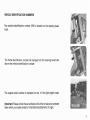
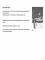
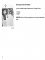
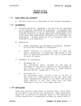
Steering lock (Fig. 1/1) helmet holder (Fig. 1/2)
To lock:
Turn handlebar to the right, insert key and push lock into
position by turning the key counter clockwise at the same time.
The lock should stay in its position after turning the key
clockwise. Pull the key off.
To unlock: Turn lock counter clockwise to free front fork.
Should you decide to lock and secure your helmet with your moped, simply
place helmet strap into position (Fig. 1/2) before turning front fork to the
right.
Fig. 2
Fig. 1
Gas tank (Fig. 2)
The gas tank is located underneath your seat.
To fill gasoline just tilt seat forward to gain accesss to filler cap (Fig. 2) and
storage compartment.
A tool set (Fig. 2/1) and measuring cup (Fig. 2/2) is included.
4
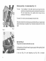
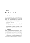
Fuel Valve (Fig. 3)
The fuel valve is positioned on the I.h. side of your seat bench.
Position 1 = closed
Position 2 = open
Position 3 = reserve
Fig. 3
Fig. 4
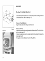
Carburetor (fig. 4)
Choke (Fig. 4/ 1). Push down to actuate it. The choke will be released automatically (see riding instructions).
Primer (Fig. 4/2). The primer button has to be held down in order to flood
the carburetor.
St op priming as soon as gas drips from carburetor.
5
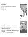
Light and Horn Switch (Fig. 5)
The light and horn switch is located on the left hand side of the handlebar.
Position 1
Position 2
=
=
light off
light on
Press button to actuate horn.
Fig. 6
Fig. 5
Engine stop switch (Fig. 6)
The engine stop switch is locat_ed on the right hand side of the handlebar.
To operate moped, the switch has to be in RUN position.
Switch to OFF in order to turn off the ignit ion, which stops the engine.
6
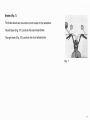
Brakes (Fig. 7)
The brake levers are mounted on both sides of the handlebar.
The left lever (Fig. 7/1) controls the rear wheel brake.
The right lever (Fig. 7/2) controls the front wheel brake.
Fig. 7
7
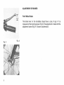
ADJUSTMENT OF BRAKES
Front Wheel Brake
The brake lever on the handlebar should have a play of app. 3/4" as
measured at the hand brake lever (Fig. 8). The adjustment is made with the
adjustment screw (Fig. 9/1) (loosen counternuts!).
Fig. 9
8
Fig. 8
Rear Wheel Brake
The brake lever on the handlebar should have a play of app. 3/4" (see
Fig. 10). The adjustment is rade with the adjustment screw (Fig. 11/1)
Fig. 10
Fig. 11
9
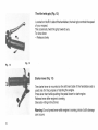
Throttle twist grip (Fig. 12)
Located on the R.H. side of the handlebar, the twist grip controls the speed
of your moped.
The accelerate, twist the grip towards you.
To slow down:
- Release slowly
Fig. 13
Fig. 12
Starter lever (Fig. 13)
The starter lever is mounte-d-on the left hand side of the handlebar and is
used only for the purpose of starting the engine.
Press lever hard while pushing the pedal down to start engine.
Release lever after engine is running.
(See also riding instructions)
Warning: Do not press lever while engine is running, since clutch damage
can occure.
10
Adjustment of Starter Clutch Cable
The starter lever should have a play of app. 112 inch as measured outside at
the lever end. The adjustment is made with the adjustment screw
(Fig. 14/1 ). The rubber cap must be slid back first.
Fig. 14
Tire Pressure
Recommended tire Pressure
Front tire: 32 psi
Rear tire: 32 psi
Caution: Proper tire pressure is important, since under inflated tires can
cause hazardos riding situations and are subject to excessive wear.
11
!".......~~::-·~-~~::---~,~•.·'IEID
Gasoline/Oil Mixture
Filling up with two stroke mixture
All MAXI engines must be run with a gas/oil mixture (regular gas). Therecommended mixing ratio is 50:1 when using special Maxi Mix two stroke
moped oiL
NOTE: DO NOT USE UNLEADED GASOLINE
PUCH MAXI MIX
50: 1 OIL MIXING TABLE
To 5 gallons gasoline add 12 fl. oz. (379 cc) oil
To 1 gallon gasoline add 2.4 fl. oz. (76 cc) oil
To 1 quart gasoline add. 6 fl. oz. (19 cc) oil
Fig. 16
Fig. 15
Use measuring cup for pruper amounts of oil.
Ask your PUCH dealer for maxi mix oil.
NOTE: When using other brands of 2 stroke oil, do not exceed the 50:1
mixing ratio.
WARNING
NEVER REFUEL W ITH THE ENGINE RUNNING!
DO NOT SMOKE OR ALLOW OPEN FLAMES OR SPARKS IN THE AREA
WHERE YOUR MOPED IS REFUELED AND/OR WHERE GASOLINE IS
STORED! CHECK WITH LOCAL AUTHORITIES ABOUT THE STORAGE OF
GASOLINE.
,
12
Transmission fluid
The oil level screw (Fig. 17I 1) serves also as the filler plug and is located on
the clutch cover.
The drain plug (Fig. 17/2) is located on the lower engine case.
To fill oil: The moped must be in a level position when oil is filled (off kickstand) .
Use automatic transmission fluid type ,F, only.
The quantity of oil is 6 s;4 fl. oz. (200 cc) or fill until oil levels off at the bottom
of the thread of filler plug.
Fig. 17
13
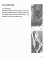
HEADLIGHT
c
Checking the Headlight Adjustment
Load vehicle (with one person or 150 LBS) and place it on even ground at a
5 m distance from a vertical wall (Fig. 18).
Measure at headlight glass:
Height of the center from the ground (H) in em.
Fig. 18a
14
Fig. 18
Place on the wall:
A centerline vertical to the longitudinal axis of the vehicle (C), and a horizontal line at the height "H".
If the light is adjusted correctly, the light-dark limit should be 5 em below the
horizontal line (H).
For higher or lower setting turn screws (Fig. 18a/1 ).
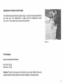
Exchanging the Headlight Bulb
Loosen screw (Fig. 19/1 ).
Push headlight covering to the top and then pull it to the front. Twist bulb socket (Fig. 20) in the direction of the arrow. Exchange bulb. When remounting the covering, make sure that the pinion of the covering (Fig. 20/1)
engages in the bore provided at the lower fork bridge.
Fig. 19
Fig. 20
15
Exchanging the Tail and Stop Bulb
Loosen the taillight screw and remove lens. Exchange the bulb.
1 Stoplight
2 Taillight
WARNING: Due to strict lighting regulations use only original replacement
bulbs.
Fig. 21
16
RIDING INSTRUCTIONS
Starting the Moped
1. Prop the moped on its stand.
2. Unlock fork.
3. Turn fuel valve to the ON position.
4. Be sure that the engine stop is in the RUN position.
5. If engine is cold, depress the choke and depress the primer button on the
carburetor until fuel drips from carburetor.
6. Keep both hands on the handlebar with the weight of the moped centered on the front wheel. Apply the front brake and fully depress the starting Lever located on the left side of the handlebar. Position the pedal
approx. parallel to the chain guard.
While holding the starter lever, push the pedal to start engine.
CAUTION: After completing step 5 and 6 do not open the throttle control,
as this will deactivate the choke. After the engine has started and warmed
up, open throttle gently to the full position briefly. This will disengage
choke. Avoid racing engine.
7. Alternate starting method:
The moped may also be started by pedalling as a bicycle. When momentum has been gained, pull the start lever and gently open the throttle.
Release the start lever after the engine starts.
17
RIDING
1. It is suggested to wear bright clothing, utilize eye protection, and proper
shoes or boots when riding your moped.
2. Wearing a helmet is recommended even though optional in many states.
See your local PUCH DEALER or check with local law enforcement
agencies for state law requirements.
3. Be sure to switch on headlight at low visibility and/or where required by
law.
Fig. 23
Fig. 22
4. The moped is designed to carry ONE person. Do not carry a passenger or
very heavy cargo. Approved PUCH saddle bags and baskets are
availaple through your dealer.
5. Obey all traffic regulations. Use hand signals when turning or changing
lanes. Please respect property of others and ride carefully. Keep your
feet on the pedals at all times. Keep the pedals level, especially on turns.
6. After reaching maximum speed, reduce the throttle opening to 3/4.
While a reduction in speed will hardly be noticeable, fuel consumption
however will be considerably reduced.
7. Closed throttle will slow down moped when riding downhill.
8. To ensure engine lubrication on long downhill rides, open throttle
occasionally.
18
General Maintenance
Should you feel able to perform small maintenance work on your moped,
make sure that all nuts and bolts are tight and all other components are in
good working condition.
A service manual is available through your PUCH dealer.
Any maintenance or service work requiring special tools and mechanical
skills should be performed by your local PUCH dealer.
NOTE: The use of non PUCH authorized spare parts can cause malfunction
and hazardous riding situations for you.
Fig. 24
Fig. 25
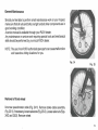
Removal of front wheel
Unscrew speedometer cable (Fig. 24/1 ). Remove brake cable assembly
(Fig. 25/1 ), if necessary, loosen setscrew (Fig. 25/3). Loosen axle nuts (Figs.
24/2 and 25/2). Remove wheel.
19
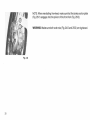
NOTE: When reinstalling the wheel, make sure that the brake anchor plate
(Fig. 26/1) engages into the pinion of the front fork (Fig. 26/2).
WARNING : Make sure both axle nuts (Fig. 24/2 and 25/2) are tightened.
Fig. 26
20
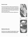
Removal of rear wheel
Remove brake cable assembly, if necessary, loosen setscrew (Fig. 27/4).
Loosen chain tensioning screws (Fig. 27/1 and Fig. 28/1 ). Loosen both axle
nuts (Fig. 27/2 and 28/2). Detach chain tensionerfrom grooves. Push wheel
forward. Remove chain (Fig. 27/3) from drive sprocket. Pull off the rear
wheel with vehicle tilted to the left.
When remounting the wheel, check chain tension and tighten axle nuts.
Fig. 27
Fig. 28
Retightening the Bolts and Nuts
Check bolts and nuts for tightness. Pay particular attention to engine
mounting bolts, front and rear axles and spring strut fastening screws.
21
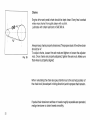
Chains
Engine drive-and pedal chain should be kept clean. Every few hundred
miles wipe chains thoroughly clean with a cloth.
Lubricate with chain lubricant or SAE 90 oil.
Fig. 29
Always keep chains properly tensioned. The proper slack of the drive chain
should be 3/4".
To adjust chains, loosen the axle nuts and tighten or loosen the adjuster
nuts. Once chains are properly adjusted, tighten the axle nuts. Make sure
that wheel is properly aligned.
When reinstalling the chain also pay attention as to the correct position of
the chain lock (closed part in riding direction) and to proper chain tension.
If pedal chain tensioner catches or travels roughly as pedals are operated,
realign tensioner so chain travels smoothly.
22
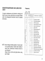
SUGGESTED MAINTENANCE AND LUBRICATION
CHART
A regular maintenance and lubrication schedule will
help to ensure a long, useful life for your moped. Please
refer to the mileage and lubrication chart for detailed
information.
Frequency
First
300 miles
Every
miles
0
0
0
g
<.0
0
0
0)
•
•
• •
•
•
•
g
,.... g
(")
•
Throttle cable adjustment
•
•
Check tire pressure
•
•
Check transmission ATF level
•
w
•
•
•
Clean and lubricate chain
•
•
•
Clean air filter
•
•
Change transmission ATF
•
•
.. , .•
Check spark plug
Decarbonize engine
• •. j•.
iI·
•
w
~
•
~
•
a:
•
•
•
Tire wear and condition
•
()
NOTE: Above milage schedule applies to moped used
on dry paved surface. If used in wet, muddy or
sandy area, maintenance intervals should be
more frequent.
Always check controls and lights before using
your moped.
•
•
•
•
0
w
•
•
•
w •
()
OPERATIONS TO PERFORM
•
•
> •
a:
~
,....
•
1
!
Clean exhaust baffle
Retighten screws and nuts.
• 1•
•
Clean fuel valve and lines
•
Clean carburetor
I
• I : : ~~::~~;~it~=~ut~::;t
:. :. Adjust starter cable
Check brake cables/linings
•
I
Check/lubricate hub bearings
.I•. •
•
• 1 • I1 • 1 •
1
1
Steering bearing adjust/lubrication
Lubricate control cables
Ad'JUSt c ham
' t ens1on
.
l l l l l I
23
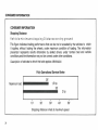
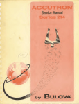
CONSUMER INFORMATION
CONSUMER INFORMATION
Stopping Distance
Vehicle minimum stopping Distance on dry ground
This figure indicates braking performance that can be met or exeeded by the vehicles to which
it applies, without locking the wheels, under maximum condition of loading. The information
presented represents results obtainable by akilled drivers under normal road and vehicle
conditions,and the information may not be correct under other conditions.
Description of vehicles to which this table applies: MINI-MAXI
Fully Operational Service Brake
28'
1,5 hp
38'
Maximum load
2 hp
10'
20'
30'
40'
50'
Stopping distance in feet at maximum speed
24
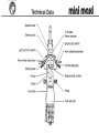
Technical Data
minlmaai
Speedometer
Steering lock
V.LN.plate
Frame number
Engine stop switch
Light and horn switch
Front wheel brake lever
Starting lever
Primer
Engine serial number
Choke
Pedal
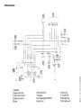
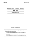
WIRING DIAGRAM
@)
cr
\2
-'
T
"'
z
z
"'
"'
cr
w
w
cr
\2
w
:::>
\2
w
:::>
., "'
..J
..J
T ll
~ ~ ~ ~ ~ ~
>- 0
a: a: cr
0
"'
B LACK
GREEN
~
z z
"' t.:l >- "'
P-
(,)
~
I
15
®~OWN
1 Headlamp
2 Speedometer bulb
3 Light and horn switch
4 Engine stop switch
5 Buzzer
--
R
L _ _j
®
®f
BLUE/BLACK
®
BROWN
.L
6 Stop light switch
7 Regulator
8 Fly wheel magneto BOSCH
9 Ignition coil
10 Spark plug
11 Taillight bulb
12 Stop light bulb
13 Stop light switch
,.....
0
(j)
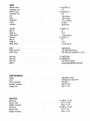
ENGINE
Maximum output
Compression ratio
Maximum output
Compression ratio
Bore
Stroke
Displacement
Cooling .
Lubrication
1.5 hp at 5000 r.p.m
8.5 :1
2.0 hp at 5500 r p.m
8.5:1
1 496 in (38 mm)
1.693 in (43 mm)
2.97 cu. in (48.8 cc)
air cooled
gas/oil mixture
Carburetor
Main jet
Needle jet
Needle position
Carburetor
Main jet
Needle jet
Needle position
1.5 hp BING 1 / 12
52
2.12 A
1 st notch from top
2.0 hp BING 1/12
54
2.12 A
1 st notch from top
Ignition . . . .
Breaker point gap
Ignition timing
Spark plug
Spark plug
Spark gap
Dynamo
POWER TRANSMISSION
Gearbox
Clutch
Primary transmission
Secondary transmission
Pedalling chain
GEAR RATIOS
Engine gear
Gear-rear wheel
Pedalling t ransmtssion
Engine gear
Gear -rear wheel
Pedalling transmission
magneto ignition
.014-.018 in (0.35-Q.45 mm)
.032-.047 in (0.8·1 .2 mm) BTDC- 14-17.50
1.5 hp BOSCH W8C
2.0 hp BOSCH W7C
.016-.020 in (0.4·0.5 mm)
flywheel magneto BOSCH 6 V 26-5/ 1OW
single speed automatic
centrifugal clutch running in ATF
helical gears
chain 1/2 "x 3/16"
chain 1/2 "x 1/8"
1.5hp96:19; i - 5.052
39:14; i - 2.785
28:23; i - 1,217
2.0 hp 96: 19; i - 5.052
39 15; i - 2.6
28:23; i - 1.2 17
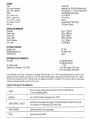
CHASSIS
Frame
Front wheel suspens1on
Rear wheel suspension
Brakes .
Dia. of brake drum
Width of brake lining
Tire size front and rear
Tire pressure front/rear
Fuel tank
tubular frame
telescopic fork; 1.96 in (50 mm) spring travel
shock absorbers; 1.77 in (45 mm) spring travel
internal expanding shoe brakes
3.15 in (80 mm)
0.7 in (18 mm)
2.50· 14"
32 psi/32 psi (2.25 bar/2.25 bar)
.93 US gal (3.5 litres)
WEIGHTS AND DIMENSIONS
Wheelbase
Overall length
Overall width
Overall height
Ground clearance
Curb weight
43.3 in. (11 00 mm)
63.8 in. (1620 mm)
28.4 in. (720 mm)
39.8 in . (1010 mm)
5.1 in. (130 mm)
105.81b (48 kg)
ELECTRICAL EQUIPMENT
Headlamp bulb
Rearlamp/Stoplamp bulb
Warning device
6V, 15W
6V, 4W/6V. lOW
buzzer
PERFORMANCE AND CONSUMPTION
Top speed
. . . . .
Hill climbing ability
.
Standard fuel consumption (DIN 70030)
1.5 hp 25 mph (40 km/h)
2.0 hp 30 mph (48 km/h)
11·14%
1.5 hp 148m/US gal (1 7811100 km)
2.0 hp 144m/US gal (1.98 1/100 km)
Test commences on a flat track in top gear at 3/4 top speed. The track length of 6.2 m (1 0 km) is used either way and may have verv short
upward and downward gradients of a maximum of 1,5%. The vehicle must be adjusted to specification and tires must have corrf!r: ...,ressure
The rider must not weight more than 143.32 lbs (65 kg). The measured consumpt1on is increased by 10% to take into account unfavourable
conditions. Production may differ up to 50fo from this value.
CAPACITY AND QUALITY OF LUBRICANTS
ENGINE
Mixture of regular grade gasoline with special two stroke 011 (M AXI MIX) 50 1.
Do not use unleaded gasoline.
GEARBOX
63f• oz. (200 cc } Automatic Transmission Fluid "TYPE F"
GREASE NIPPLES. CABLES
Summer and winter grease. For lubricat ion o f the grease nipples also SAE 90 can be used.
For lubrication of the cables also SAE 30 can be used.
WHEEL BEARING
CHAIN
I
Summer and winter i..ithium base grease.
Summer and winter SAE 90.
ASSENBLY INSTRUCTIONS - PUCH NINI NAXI
1. Remove the Moped from its container.
2. Set the Moped on its kick stand.
J.
Remove accessory box from container.
4. Begin assembly by removing protective packing.
5.
Install front fender and secure with the four
(4)
screws provided
(screws are located in the fork sliding tubes).
6. Install front wheel and torque axle nuts to 35-50 Nm
(25-36 ft/lbs).
Note: Both axle nuts and washers are located on one (1) side of the
axle. Install front \Yheel with brake reacting slot on left hand
side (operator's view).
Assure that brake stop on fork leg and brake backing plate inter lock. Connect speedo cable and check for speedo operation.
7. Position the handlebar on the fork bridge, making sure electrical
wiring is not crossed. Attach with the four (4) allen head bolts
provided. Before torquing bolts, align the handlebar so that it
is running parallel with the front fork. Torque bolts to 15-16 Nm
(10-12 ft/lbs).
8. Place throttle twist grip into shackle and mount to handle bar.
9. Hount both electrical switches and secure wiring with the
tie- wraps to the handle bar.
Caution: secure electrical wiring only, not brake cables.
10.Install front brake cable
and adjust brake.
11.Install pedals. Note: Pedals are marked "L" - l e f t hand side,
and "R 11 - ri_ght hand side.
12.Install rearview mirrorand adjust as requJ..red.
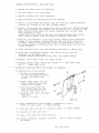
1J.Installation of leg shield:
a) locate the four sleeves
( 1) into the mounting holes.
of' the leg shield, see
arrow.
b) place lower clamp (2) over
frame tubing and position
sleeve (3) in clamp.
c) position leg shield (4)
over lo1ver clamp (2) and
install clamp stud (5) •
d) install both upper mounting
bolt (6),
Tighten all nuts.
14, Fill transmission with automatic transmission fluid
F only) refer to owners manual.
(TYPE
-
15. Fill gas tank with gas oil mixture, refer
to owners manual.
16. Tighten all nuts and bolts
17. Short test drive and clean machine.
18. Please, carefully instruct customer
the moped.
how to safely operate