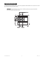
1
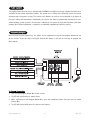
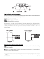
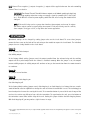
Security and Convenience Components
519H Three-Channel Receiver
FCC/ID Notice
This device complies with Part 15 of FCC rules. Operation is subject to the following two conditions: (1) This
device may not cause harmful interference, and (2) this device must accept any interference received, including
interference that may cause undesired operation.
CAUTION: Changes or modifications not expressly approved by the party responsible for compliance could void
the user’s authority to operate this device.
XR
What Is Included
■ Control module
■ Two remote transmitters
■ 3-Pin main harness
■ 3-Pin secondary harness
■ Receiver harness
■ Power adapter
■ Venom XR receiver/antenna
Compatible Transmitters
The receiver is compatible with all of the following Directed Electronics transmitters:
■ Directed Electronics 266 bit transmitters: 470T, 475 Series, 476 Series and 471 Series
■ Clifford G4 transmitters: 3-button Cello, 4-button OEM, and Radar Master
■ Avital transmitters: 2-button P/N 820021, 3-button P/N 820031 and 4-button P/N 820041
© 2005 Directed Electronics, Inc.
1
N519H 04-05
Product Description
The 519H 3-Channel Receiver uses a computer-based EEPROM Learn Routine to assign individual functions to be
controlled by the remote transmitter buttons. The system uses a rolling code, Venom XR receiver to provide
improved range and greater security. The receiver Learn Routine can also be used to program up to twelve of
Directed’s rolling code transmitters. Additionally, the receiver will store the programmed transmitters in nonvolatile memory, so that if power is lost and then reconnected, the system can recall the transmitter codes from
memory. Once initial programming is completed, no additional programming should be required.
Programming the System
Once the unit has been powered up, the system can be programmed using the two program buttons on top
of the receiver. If you will only be using the Channel One output, it will not be necessary to program the
other outputs.
To Program Channel One
1. Press and hold Program Button One on the receiver.
2. The LED will start flashing in groups of one.
3. While continuing to hold Program Button One, press the transmitter button that you want to control
Channel One.
4. The LED will light steadily when the code has been learned.
© 2005 Directed Electronics, Inc.
2
N519H 04-05
To Program Channel Two
1. Press and hold Program Button Two on the receiver.
2. The LED will start flashing in groups of two.
3. While continuing to hold Program Button Two, press the transmitter button that you wish to control
Channel Two.
4. The LED will light steadily when the code has been learned.
To Program Channel Three
1. Press and hold both program buttons on the receiver simultaneously.
2. The LED will start flashing in groups of three.
3. While continuing to hold both program buttons, press the transmitter button(s) that you wish to control
Channel Three.
4. The LED will light steadily when the code has been learned.
Zap Feature
All of the remote transmitters can be deleted from the system's memory by using the Zap feature:
1. Disconnect power from the unit.
2. Press and hold Program Buttons One and Two on the receiver simultaneously.
3. While holding down the program buttons, reconnect power to the unit. Continue to hold down the program
buttons until three seconds after power has been reconnected.
4. The LED will light for one second to indicate that all the remote transmitters have been erased from
the system.
Installation
Using the 519H as a Garage Door Interface
The unit should be mounted in a location where a 110 VAC receptacle and the wall mounted garage door switch
wires can both be easily accessed.
Using the 519H in a Vehicle Application
1. Cut the power adapter wire in half, approximately six inches away from the power adapter’s transformer.
2. Using the plug side of the power adapter, insert the plug into the power jack receptacle.
3. BLACK/WHITE: Fuse this wire using a 10-amp fuse and fuse holder. Connect the wire to the battery positive
terminal or the constant 12V supply to the ignition switch.
4. BLACK: Remove any paint and connect this wire to bare metal, preferably with a factory bolt rather than your
own screw. (Screws tend to either strip or loosen with time.) See the following diagram.
© 2005 Directed Electronics, Inc.
3
N519H 04-05
Channel One Relay Harness (3 wires, heavy gauge)
These wires are connected to the terminals of the on-board Channel One relay. When the control module receives
the code programmed into Channel One**, this relay is activated.
YELLOW: Relay common, terminal #30
BROWN: Relay normally open, terminal #87
ORANGE: Relay normally closed, terminal #87A
To interface with a garage door opener, first determine if the garage door opener's wall switch connects (normally open switch type), or disconnects the wires (normally closed switch type). Most garage door openers use
a normally closed switch. Once the switch type has been determined, interface with the module as shown in the
following diagrams.
Channel Two and Three Mini-Harness (3-wires, light gauge)
GREEN Channel Two negative (-) output: The module will output a negative pulse whenever the code controlling
Channel Two is received.**
RED positive (+)12V constant output: This output is used to power the coil (terminal 86) of any relays that are
used with the Channel Two or Three outputs.
* If no code is programmed into the unit, no output will be supplied. Please refer to the “Programming The System” section of this guide
for details.
© 2005 Directed Electronics, Inc.
4
N519H 04-05
BLUE Channel Three negative (-) output: A negative (-) output will be supplied whenever the code controlling
Channel Three is received.**
IMPORTANT! The Channel Two and Three Mini-Harness outputs are all 200mA capable and should not
be used to drive anything other than a relay or to supply a signal to a module (551T, 529T, 530T,
etc.). If the RED wire is used to power anything other than the coil of a relay, the module will be
damaged.
NOTE: If the unit is being used as a garage door interface, these outputs can be used in conjunction with a relay to control a second garage door opener. If the unit is being used in a vehicle,
these outputs can trigger a 551T, or any other low current application.
Internal Programming
Operational settings can be changed by cutting jumper wires on the circuit board. To access these jumpers,
remove the four screws on the back of the unit and open the module to expose the circuit board. The individual
jumper wires are clearly labeled on the circuit board.
Jumper J1
Uncut (default): Pulsed output
Cut: Validity output
In the factory default setting (jumper uncut) the output provided from the on-board relay and the auxiliary
outputs will be a pulsed output when the channel is activated remotely. When the jumper is cut, the outputs
become validity outputs. A validity output will continue as long as the transmission from the remote transmitter continues.
Jumper J2
This jumper has no function.
Jumper J3
Uncut (default): Code Hopping on
Cut: Code Hopping off
In the factory default setting (jumper uncut), Code Hopping is on. Code Hopping is a feature that uses a mathematical formula called an algorithm to change the code each time the transmitter is used. This technology has
been developed to increase the security of the unit. If a transmitter button is pressed while out of range of the
receiver, the receiver may fall out of sync with the transmitter. To resynchronize the unit, press the button on
the transmitter several times within range of the unit. Cutting this jumper disables the Code Hopping feature.
With Code Hopping off, you may notice a slight increase in range.
* If no code is programmed into the unit, no output will be supplied. Please refer to the “Programming The System” section of this guide
for details.
© 2005 Directed Electronics, Inc.
5
N519H 04-05
Manual Operation from the Receiver
To manually operate the 519H, press and release the appropriate channel button on the receiver for less than
one second to activate the desired channel.
IMPORTANT! If a channel button on the receiver is held for more than one second, the 519H will
enter the transmitter programming mode.
© 2005 Directed Electronics, Inc.
6
N519H 04-05