1
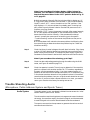
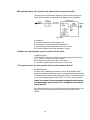
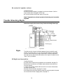
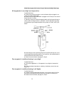
Scoreboard
Installation
and Service
Manual
F290 Rev 0600
Colorado Time Systems
Corporate Office
1551 East 11th Street
Loveland, CO 80537 USA
Sales : 800-279-0111 or +1 970-667-1000
Service: 800-287-0653 x256 or +1 970-667-1000 x256
Service Fax: 970-667-1032
Web: www.coloradotime.com
Shop online: http://secure.coloradotime.com
Email: [email protected]
Part Number F290, Rev. 0600
©2000. Colorado Time Systems, llc. All rights reserved.
Table of Contents
1 Introduction
Receiving Your Equipment . . . . . . . . . . . . . . . . . . . . . .1-1
2 System Components and Definitions
Optional Accessories . . . . . . . . . . . . . . . . . . . . . . . . . . .2-3
3 Scoreboard Mounting
Mounting Using Portable Stands . . . . . . . . . . . . . . . . .3-1
One-Line Module . . . . . . . . . . . . . . . . . . . . . . .3-1
Two-Line Module . . . . . . . . . . . . . . . . . . . . . . .3-2
Optional Caddy . . . . . . . . . . . . . . . . . . . . . . . . .3-2
CAD-P Assembly Instructions . . . . . . . . . . . . .3-3
Mounting Using Pole Mounts . . . . . . . . . . . . . . . . . . . .3-4
Mounting Using Wall Mounts . . . . . . . . . . . . . . . . . . . .3-7
Fence Mounting . . . . . . . . . . . . . . . . . . . . . . . . . . . . . . .3-10
4 Lightning Protection Recommendations
Introduction . . . . . . . . . . . . . . . . . . . . . . . . . . . . . . . . . .4-1
Installation Materials and Specifications . . . . . . . . . . .4-2
Ground Rods . . . . . . . . . . . . . . . . . . . . . . . . . . .4-2
Conductors . . . . . . . . . . . . . . . . . . . . . . . . . . . .4-2
Bonding . . . . . . . . . . . . . . . . . . . . . . . . . . . . . . .4-3
Installation . . . . . . . . . . . . . . . . . . . . . . . . . . . . . . . . . . .4-3
Ground Rods . . . . . . . . . . . . . . . . . . . . . . . . . . .4-3
Conductor Routing . . . . . . . . . . . . . . . . . . . . . .4-5
5 Scoreboard Wiring and Connections
Control Board . . . . . . . . . . . . . . . . . . . . . . . . . . . . . . . . .5-1
Selector Switch for Control Boards . . . . . . . . .5-4
Electrical Power Requirements . . . . . . . . . . . . . . . . . . .5-5
Speaker(s) . . . . . . . . . . . . . . . . . . . . . . . . . . . . . . . . . . . .5-5
Operator’s (Keyboard) Console . . . . . . . . . . . . . . . . . . .5-5
Optional Wall Box (Model WB-1) . . . . . . . . . . . . . . . . .5-5
One Scoreboard with Wall Box . . . . . . . . . . . .5-6
One Scoreboard with Direct Wiring . . . . . . . .5-7
Two Scoreboards with Direct Wiring . . . . . . .5-7
Two Scoreboards with Wall Box . . . . . . . . . . .5-7
6 Power Requirements
AC Operation . . . . . . . . . . . . . . . . . . . . . . . . . . . . . . . . .6-1
Internal DC Battery Operation . . . . . . . . . . . . . . . . . . .6-1
Battery Charge . . . . . . . . . . . . . . . . . . . . . . . . .6-1
Battery Recharging . . . . . . . . . . . . . . . . . . . . . .6-2
Battery Installation and Replacement . . . . . .6-2
External Battery Operation . . . . . . . . . . . . . . . . . . . . .6-2
Power ON/OFF . . . . . . . . . . . . . . . . . . . . . . . . .6-2
Connecting the External Battery Pack . . . . . .6-2
Correct Use of ON/OFF Switch . . . . . . . . . . . .6-3
7 Service
What To Do If “Nothing” Works . . . . . . . . . . . . . . . . . .7-1
Trouble Shooting—Audio . . . . . . . . . . . . . . . . . . . . . . .7-2
Trouble Shooting—Digits . . . . . . . . . . . . . . . . . . . . . . .7-4
Segment Repair and Maintenance . . . . . . . . . .7-6
Testing Digit Coils . . . . . . . . . . . . . . . . . . . . . .7-6
How to Remove a Digit . . . . . . . . . . . . . . . . . . .7-7
Trouble Shooting—Operator’s Console . . . . . . . . . . . .7-7
Trouble Shooting—Electrical Power . . . . . . . . . . . . . .7-9
Electrical Power—#2860 Control Board . . . .7-10
Electrical Power—#4290 Control Board . . . .7-10
Trouble Shooting—Data Cable . . . . . . . . . . . . . . . . . . .7-10
Trouble Shooting—Speaker . . . . . . . . . . . . . . . . . . . . .7-12
Trouble Shooting—Optional Battery . . . . . . . . . . . . . .7-12
To Charge the Battery . . . . . . . . . . . . . . . . . . .7-13
To Replace the Battery . . . . . . . . . . . . . . . . . . .7-13
Long-Term Battery Storage . . . . . . . . . . . . . . .7-14
How to Remove the Control Board . . . . . . . . . . . . . . . .7-14
8 Scoreboards Two-Year Limited Warranty
. . . . . .8-1
1
Introduction
Dear Customer:
Please accept our thanks for choosing Colorado Time Systems as your
scoreboard company. Your new scoreboard combines simplicity of installation with ease of operation. Mounting is quick and easy to accomplish with
only minimal tools.
This manual provides instructions for installation of your scoreboard system. It is recommended that you set aside a few minutes to familiarize
yourself with this manual before you attempt to install the equipment.
Begin by using the Table of Contents to select which type of installation is
applicable to you. For all outdoor mounted scoreboards, we suggest you
consult Chapter 4 - Lightning Protection Recommendations.
Colorado Time Systems' scoreboards are designed for easy maintenance.
Modular components aid in fast "trouble shooting" and easy repair or
exchange. If during installation you experience any problems, confirm that
you are following all directions. If you continue to exerience problems,
contact our Customer Service Department for assistance.
After installation, please use the operational section to familiarize yourself
with how to operate your scoring system.
Should your scoreboard experience any malfunction, please refer to the
service section of this manual for trouble shooting techniques and repair
instructions.
If additional assistance is required, please contact our Customer Service
Department at:
Colorado Time Systems
Attention: Customer Service Department
1551 East 11th Street
Loveland, CO 80537
Toll Free U.S. and Canada: 800-287-0653 ext. 256
Phone: 970-667-1000 ext. 256
Fax: 970-667-1032
Receiving Your Equipment
Immediately upon receipt of your equipment, take a few minutes to
perform the following steps:
1) Open all shipping boxes.
Note: We recommend that you save all shipping boxes and packing
material. You are responsible for damage to your equipment if an
item is returned improperly packed.
1-1
2) Check all concealed damage immediately upon receipt of equipment.
Report any damage directly to the freight carrier.
3) Use the packing list included with the shipment to take an inventory of
all items. If you believe one or more parts to be missing, contact our
Customer Service Department immediately at, ext. 256, 800-CTS-0653 in
the U.S. and Canada, or at 970-667-1000.
4) Check the connector at each digit to ensure they were not removed during shipment. Check the individual yellow digit segment on each digit (on
occasion, the yellow segment may have shaken loose during shipment).
Also, check the connectors on the scoreboard's control board to be certain
they have not shaken loose during shipment.
Note: Never apply lubricants of any kind onto the digit bearings.
1-2
2
System Components and Definitions
The following items are used throughout this manual. A working knowledge of them increases your potential for successful installation and operation. Your system consists of the following components:
Operator's Console (or keyboard console): The unit the scoreboard
operator uses to enter information transmitted to the scoreboard, see
Figure 1 below.
Figure 1: Operator's Console
Scoreboard Display (or clock): The scoreboard unit itself. It displays
scores, time, other game (or race) related data and is viewed by the
spectators and participants. See Figure 2 below.
Figure 2: BB2 Scoreboard
2-1
Main Control Board: The printed circuit board that contains all the
electronic components needed to operate the scoreboard and console,
and therefore is considered the "brain" of the system. It is located internally on the right-hand side of the scoreboard as you face the board. See
Figure 3 below.
#4290
#2860
Figure 3: Main Control Boards
Note: Two types of control boards are used in scoreboards
depending on the year the scoreboard was manufactured. The
control board used before December 1998, #2860 board is illustrated in Figure 29, page 5-1. The control board that was used
after December 1998 is the #0066 - 4290 board (See Figure 30,
page 5-2).
Individual Digits (either nine or twelve inches in height): The
seven-segment flip displays that are found in the scoreboard, display
numbers for the various functions, i.e. "Score" and "Time."
Figure 4: Individual Digits
Data Cable: The communication cable that transmits the data and
audio signals from the operator's console to the scoreboard. See Figure 5
below.
Figure 5: Data Cable
2-2
Digit Enable Cable: The cable (ribbon style) inside the scoreboard, that
connects the scoreboard digits to the control board.
Microphone: Allows for operator to use the scoreboard as a PA system. It
connects to the operator’s console. See Figure 1.
Speaker: Attaches to the scoreboard (main control board) allowing it to
work as a PA system. See Figure 3.
Interconnect Cables (two line scoreboards only): Two cables, one
originating from the back of the top scoreboard module and the other
cable from the bottom module. Must be connected for scoreboard
operation.
Weather Shield: The rectangular piece of polycarbonate on the front of
the scoreboard that protects the internal components from weather,
projectiles and tampering.
Optional Accessories
WB-1 Wall Box: Junction box used in permanent installations as shown
in Figure 6.
Figure 6: Wall Box, WB-1
MA-1 Music Adapter: Interface cable between tape player (not included)
and microphone jack on operator's console to access scoreboard amplifier.
Allows you to play songs over the scoreboard's built-in PA system. Twentyeight (28)-inch length. See Fig. 7.
Figure 7: Music Adapter, MA-1
CA-1 Cigarette Lighter Adapter: Power cord from automotive cigarette lighter receptacle to scoreboard allowing operation from car battery.
40-feet length. See Fig. 8.
Figure 8: Cigarette Lighter Adapter, CA-1
2-3
BP-3 External Battery Pack: 12V gel-cell rechargeable battery used as
external power source for the scoreboard.
CAD-P Caddy: Wheeled base for 60-inch wide scoreboards. The scoreboard clamps to a unistrut frame mounted on four 8-inch tires. Some
assembly required. See page 3-3.
Figure 10
2-4
3
Scoreboard Mounting
Mounting Using Portable Stands
One-Line Module
This operation is easiest to accomplish with the scoreboard/clock module
lying on a raised flat surface such as a table. Be sure to place the scoreboard module right side up to avoid mounting the module upside down.
The module will have the main control circuit board (located inside the
module) on the right side as you face the front of the unit.
Step 1: Place the module on its back over a flat raised surface.
Step 2: Place one leg from the portable stands into the module’s formed
endplate. Slide the leg into the endplate. See Figure 11. Align the portable
leg’s top pre-drilled hole with the hole in the endplate. Slide the quickconnect pin through the hole far enough to capture the first leg. Slide the
second leg through the endplate and insert the quick-connect pin into the
endplate.
Figure 11: Portable Stands
3-1
Step 3: Repeat Step 2 for the other side of the module.
Step 4: If you purchased a Sponsor Panel, Model SP-A, the sponsor module mounts above the top module as shown in Figure 11. Place the sponsor
module above the top module. Overhang one end of the sponsor module
and slide the flange extrusion into the top channel of the module. Repeat
for the other side.
Two-Line Module
This operation is similar to the “one-line module” mounting. Be sure to
place the scoreboard modules right side up to avoid mounting the modules
upside down.
Step 1: Place the bottom module on its back over a flat raised surface.
Note: The bottom module’s interconnect cable to the top module
and the serial number are located in the lower right side of the
module as you face the front of the unit.
Step 2: Align the portable leg’s bottom pre-drilled hole with the hole in
the bottom module’s endplate. Slide the legs from the portable stands
through the module’s formed endplates and slide the quick connect pins
through.
Step 3: Align the portable leg’s top pre-drilled hole with the hole in the
top module’s endplate and slide the quick connect pins through.
Step 4: Slide the black ABS plastic sign into the channel between the top
and bottom module.
Note: If you purchase a sponsor panel, Model SP-A, refer to Step 4
“One-Line Module.”
Optional Caddy
If you purchase the optional caddy with wheels, Module CAD-P, first
mount the portable legs to the scoreboard following the instructions provided. Then retrofit the caddy to the assembled scoreboard.
Figure 12: CAD-P Caddy
3-2
CAD-P Assembly
Instructions
Step 1: Install pole stands (supplied with caddy) into scoreboard using
quick connect pins.
Step 2: Bolt stand clamps (8 each) to Unistrut in locations shown using
1/4-inch - 20 screws, lockwashers and nuts.
Step 3: Bolt wheels to Unistrut using 3/8-inch bolts, lockwashers and
sprint nuts.
Step 4: Install pole stands into pole stand clamps and secure with 1/4-inch
- 20 screws, lockwashers and nuts.
Figure 13: Caddy Assembly
3-3
Mounting Using Pole Mounts
Pole Placement
Figure 14: Pole Mounts
Note: See the Pole Placement Table on the following page for various Dimension “A” measurements according to scoreboard model.
Begin by installing your poles. See Figure 14 for specifications.
Note:
1. Owner or contractor must obtain any local permits required
prior to commencing with construction.
2. Prime pipe prior to setting in concrete. Field paint after setting.
3. Concrete shall have a minimum compression strength of 3,000
p.s.i. in 28 days.
4. Pole base holes and mounting poles shall be vertical.
5. The dimensions and specifications shown herein are for scoreboards erected in locations where the following conditions exist:
a. Maximum basic wind speed = 80 M.P.H.
b. Minimum lateral soil bearing capacity = 1,500 P.S.F.
A licensed soils/structural engineer should be consulted when local conditions vary from the above conditions. Wind design shall equal or exceed
sections 2311 in the latest edition of the Uniform Building Code (UBC).
3-4
Table: Pole Placement
(Center to Center)
Scoreboard Model
BA-1, FS-1, BB-1,2,3
FB-1, FB-2, BA-2, BA-4
P-1, BA-3, RT-1,2, RT-4,5, P-3, P-4
TN-1,2, MS-9, MS-12
Dimension “A”
7’0”
6’0”
4’0”
4’0”
Although we have recommended minimum standards for pipe selection
and installation, the responsibility rests with you to determine whether:
(1) the installation complies with local building codes and standards, (2)
the ground installation is proper for the soil and locale (we recommend
you consult a local structural engineer), and (3) proper precautions have
been taken for lightning and surge protection (see Chapter 4--Lightning
Protection Recommendation).
Step 1
First determine the total number of modules you are installing:
a. a one-line scoreboard module only for a total of one module. (Example:
Model BA-1, Model FS-1, Model RT-2/4, Model BB-1).
b. a one-line scoreboard module with sponsor panel module for a total of
two modules. (Example: Model BA-1 with SP-E, Model FS-1 with SP-E,
Model RT-2/4 with SP-E, Model BB-1 with SP-E).
c. a two-line scoreboard only for a total of two modules. (Example: Model
BA-2, Model FB-1, Model FB-2, Model TN-1/2).
d. a two-line scoreboard with a sponsor panel for a total of three
modules. (Example: Model BA-2 with SP-D, Model FB-1 with SP-D,
Model FB-2 with SP-D, Model TN-1/2 with SP-B or SP-C).
Ground Level
Figure 15
Note: It is easier to connect the mounting brackets to the pole
keeping them loose, then connect the scoreboard at ground level.
You can then slide the scoreboard and brackets to the needed
height and secure.
You may have to adjust the bottom module after sliding in your
signage to obtain a secure fit.
3-5
Step 2
Begin by mounting the top (uppermost) module, either the sponsor panel
module if applicable or the top line of the scoreboard module. Position the
scoreboard mounting brackets into the top and bottom channel of the
scoreboard module (or sponsor panel module), see Fig. 15.
Step 3
If a third module is applicable, leave a 9 1/2 inch separation between
modules for the signage, and mount the module as before.
Step 4
Mount the black ABS sign panel.
To mount top sign panels, place the panel in the top outer edge of the
scoreboard groove. Position sign brackets at each of the pre-drilled hole
positions on the sign panel. Secure the brackets in the top frame by twisting the lock in place. Tilt the sign back to engage the bracket fingers in the
sign panel holes. Thread wire nuts onto the top fingers protruding from
the sign panels, see Fig. 16 below.
Figure 16
Or, if the signage panel mounts between two modules, slide the signage
into the channel between the top and bottom modules, see Fig. 17 below.
Figure 17
3-6
Note: For Model FB-2 Football/Baseball Combination Scoreboard,
two middle sign panels are included, one for football and one for
baseball. Slide the appropriate signage in the channel between the
top and bottom scoreboard modules. To change sports, slide the
first signage out and the second signage into the channel.
Mounting Using Wall Mounts
Match the mounting brackets to type of scoreboard as shown in Fig. 18
below. It is your responsiblity to supply appropriate hardware to match
your wall composition. We suggest you consult a local structural engineer
for recommendations and approval of the hardware and mounting method.
Figure 18
3-7
Step 1
First determine the total number of modules you are installing:
a. a one-line scoreboard module only for a total of one module. (Example:
Model BA-1, Model FS-1, Model RT-2/4, Model BB-1).
b. a one-line scoreboard module with sponsor panel module for a total of
two modules. (Example: Model BA-1 with SP-E, Model FS-1 with SP-E,
Model RT-2/4 with SP-E, Model BB-1 with SP-E).
c. a two-line scoreboard only for a total of two modules. (Example: Model
BA-2, Model FB-1, Model FB-2, Model TN-1/2).
d. a two-line scoreboard with a sponsor panel for a total of three
modules. (Example: Model BA-2 with SP-D, Model FB-1 with SP-D,
Model FB-2 with SP-D, Model TN-1/2 with SP-B or SP-C).
Step 2
Begin by mounting the top (uppermost) module, either the sponsor panel
module if applicable or the top line of the scoreboard module.
Measure, mark and drill mounting holes using dimensions provided. Make
sure holes are level by measuring up from the floor or down from the ceiling, and/or by using a level.
Step 3
Select the longer brackets (the brackets with pre-drilled holes) located in
your WM-4 or WM-5 kit. Slip the correct number of wall brackets into the
top channel on the rear of your scoreboard module (or sponsor panel module) as Fig. 19 illustrates below. Position them as shown in Fig. 18 on the
previous page 3-7.
Figure 19
Slide the two small brackets (the brackets without holes), located in your
WM-4 or WM-5 kit, into the bottom channel of the same module. These
smaller brackets serve as leveling devices and do not require bolting to the
wall.
Raise the scoreboard module to mounting position as marked and drilled
in Step 1. Mount using the appropriate hardware.
3-8
Step 3
Leave a 9 1/2 inch separation between modules for the signage, and mount
the second module underneath the top module using the same procedure
as in Step 2.
Note: You may have to adjust the bottom module after sliding in
your signage to obtain a secure fit.
Step 4
If a third module is applicable, leave a 9 1/2 inch separation between
modules for the signage, and mount the module as before.
Step 5
Mount black ABS signage panel.
To mount the top sign panels, place the panel in the top outer edge scoreboard groove. Position sign brackets at each of the pre-drilled hole positions on the sign panel. Secure the brackets in the top frame by twisting to
lock in place. Tilt the sign back to engage the bracket fingers in the sign
panel holes. Thread wire nuts onto the top fingers protruding from the
side panel, see Fig. 20 below.
Figure 20
Or if the signage panel mounts between two modules, slide the signage
into the channel between the top and bottom modules.
For owners of Model BB-1 and BB-3, a third signage for wrestling
(“SCORE” “WT. CLASS” “SCORE”) mounts to the bottom of the BB-3
module.
3-9
To mount your bottom sign panel, follow these steps:
a. Place the panel in the bottom groove of the module (BB-3).
b. Slide the sign panel brackets (inverted) into the bottom channel of the
module (BB-3).
c. Position sign brackets at each of the pre-drilled hole positions of the
sign panel.
d. Tilt the sign panel back to engage the bracket fingers protruding from
the sign panel.
e. Thread wire nuts on the top fingers protruding from the sign panel.
Note: The signage should be aligned to the far left as you face the
scoreboard. The “open” space to the right permits placement of
speaker(s) into the channel of the BB-3 module, see Fig. 21 below.
Figure 21
Fence Mounting
Fence mounting of scoreboard is prohibited. A fence acts like an antenna
and tends to attract and promote induced voltages as in lightning and static discharge.
Note: Your warranty exlcudes “acts of God” such a lightning. (See
Chapter 4 - Lightning Protection Guidelines for Outdoor Mounted
Scoreboards on page 4-1.)
3-10
4
Lightning Protection Recommendations
Introduction
These guidelines are designed to facilitate the installation of lightning protection on all outdoor mounted scoreboards. We recommend owners of outdoor scoreboards install lightning protection, and hope this information
assists you with the installation.
Our warranty, as with most manufacturers’ warranties, excludes vandalism and “acts of God”--which include lightning. With this in mind, we suggest that you check with your local insurance company to investigate protection for your scoreboard investment.
Lightning protection starts with proper grounding. For CTS scoreboards, a lightning protection system consists of three basic parts:
1. A system of ground rod(s).
2. A conductor system connecting the scoreboard to the
ground rod(s) and the main ground systems.
3. Bonding of the conductor to the scoreboards and ground
rod(s).
Lightning is an interesting and potentially life threatening phenomenon.
It produces currents from a few hundred to over a million amperes and
voltages from a million to a hundred million volts. The nature of lightning
is the same characteristic on which electronic circuits work. Current in an
electronic circuit always seeks “the path of least resistance”. This is the
same for lightning; it seeks the path of least resistance through ionized
atmosphere until it reaches ground potential at the earth. The basic difference between the currents in lightning and a circuit, other than the magnitude, is that the current in a circuit is controlled by various electrical components, but lightning is not controlled. Herin lies its potential for
danger.
A lightning protection system in effect attempts to place some “control”
over this “uncontrolled phenomenon” by shielding equipment from the
effects of harmful conducted or induced currents. The system creates a low
impedance path to ground and effectively diverts the charge away from the
device under protection. Important to note that protection systems
are not guaranteed against direct hits due to the inherent power
involved. Two terms need clarification. First, “conducted currents” refers
to a direct hit or a sideflash. Second, “induced currents” refers to a strong
electrical field that can be transferred through the atmosphere to a path of
least resistance.
4-1
Installation Materials and Specifications
Ground Rods
1. Should not be less than 1/2 inch (12.7mm) in diameter and 8 feet (2.4m)
long, see Fig. 22 below.
Figure 22
2. Composition shall be copper clad steel, solid copper or stainless steel.
3. Ground plates and other rod configurations can be used in rocky or
sandy conditions.
4. Underground metallic piping could be used as a substitute ground.
Conductors
1. Conductors can be in the form of stranded cables, single wires/rods or
flat strips.
! Stranded Cables - 17 AWG per strand, 187 lbs./1000 ft.
! Single Wire/Rods - 3 or 4 AWG, 41,000-57,000 CM (circular mils)
! Flat Strips - Thickness of 16 AWG, width 1 inch
2. Bends should not be less than 90 degrees and should not have less than
an eight-inch radius, see Fig. 23 below.
Figure 23
3. A corrosion preventative should be applied 3 feet above ground and
extended to the bonding with the ground rod. The form can be a plastic
coat, conduit, rubber hose or electrician’s tar type seal and wrap.
4-2
4. Metallic mounting structures can be used as down conductors only if
electrically bonded to the scoreboard and ground rod.
Bonding
1. Bonding to conductors can be made by welding, brazing or clamping
with at least two bolts, see Fig. 24A below.
2. Stranded cables can be installed with terminal lugs for ease of installation and to prevent fraying, see Fig 24B below.
Figure 24
3. When bonding copper to the aluminum scoreboard frame, a bi-metal
shim is needed to buffer the characteristics of dissimilar metals. This will
prevent harmful electrolytic action or the storage of charge between two
different elements, see Fig. 24C above.
4. Miscellaneous bonding hardware (see Fig. 24D) can be used for common
ground bonding.
Installation
Ground Rods
At least one ground rod is required for each scoreboard module, except for
a bank of scoreboards. When a bank of scoreboards (a series of 3 or more
modules) are mounted together, two ground rods are required, one on each
side.
Before driving the ground rod into the soil, make sure there are no obstacles beneath ground level where you have selected to install the rod.
Obstacles would include telephone lines, power lines, water pipes, gas
pipes, etc.
Select an installation position as close to the scoreboard as possible and
drive the 8 foot rod, two feet below the ground level, see Fig. 25 on the
following page.
Most installations will be done in moist clay-type soil; however, when gravelly or sandy conditions are encountered, additional ground rods would be
required at a minimum spacing of 10 feet, see Fig. 26 on the following
page. Where bedrock prevents rods from being driven to a 10 foot depth,
the conductor and rod should be laid in trenches horizontally not less than
12 feet at a depth of 1 or 2 feet in moist clay-like soil. For sandy or gravelly
conditions, the trenches should not be less than 24 feet in length and not
less than 2 feet in depth. Copper plates 0.032 inch thick and a two square
foot surface can be used where the soil is less than one foot deep.
4-3
Figure 25
Figure 26
An acceptable substitute ground rod can be a metallic water pipe as long
as it extends at least 10 feet below grade.
The lightning protection grounding system should be connected to the
building system ground if the scoreboard is mounted to a building structure or to the power system ground if the scoreboard is located in a remote
area. This requirement is necessary for common ground potentials and for
meeting appropriate applicable electrical codes. Check your local codes.
4-4
Conductor Routing
Refer to the “Bonding” section under “Installation Materials and
Specifications” for bonding conductor to the ground rod and scoreboard
frame.
Once the conductor is bonded to the ground rod, it needs to be protected
from corrosion 3 feet above the ground level to the bonding with the
ground rod. Electrician’s tar type seal and wrap would be the most appropriate, but a cured plastic coat or sealed conduit could also be used.
Down conductors need to be guarded from physical damage and displacement. A minimum of 6 feet should be protected above ground level. PVC
conduit is acceptable.
Make sure that any bends in the conductor do not have less than an 8-inch
radius. This provides a smoother path for current to flow, see Fig. 23 on
page 4-2.
A down conductor is recommended from each end of the scoreboard.
Attach the conductor bolt in the scoreboard endplate where applicable
using a terminal lug and bi-metal shim (see Fig. 24B & 24C, page 4-3).
Where pole mounting and endplates are present, drill a hole in the aluminum frame above or below the back ABS black plastic panel using the
same bonding hardware, see Fig. 27 below. The inside of this hole can be
reached from the top of the scoreboard. Make sure the anodized aluminum
is removed where the conductor is mounted.
Figure 27
If the scoreboard is mounted to a metallic mounting structure, the structure can be substituted for the main conductor only if it is at least 3/16
inch thick and meets the cross-sectional area of 57,000 cm. In addition,
wherever the scoreboard is bolted to this structure via unistrut or other
painted hardware, remove the paint in that area to make a good
connection.
In a few cases, the metallic mounting structure extends below the ground,
deep enough to eliminate the ground rod. In this case, the structure needs
to be connected to the main system ground. This eliminates any ground
potential differences. The majority of mounting structures are secured in
concrete.
4-5
Concrete acts as an insulator, therefore, the structure needs a ground rod.
Note: Fence mounting of scoreboards is prohibited. A fence acts
like an antenna and tends to attract and promote induced
voltages.
SOURCE:
NFPA 78 Lightning Protection Code. 1986 Edition. National Fire
Protection Association, 1986.
4-6
5
Scoreboard Wiring and Connections
Control Board
Step 1
Depending upon the particular model you have purchased, you will need to
connect several items to the main control circuit board. The control board
is located on the right-hand side of your scoreboard (the top module if you
purchased a two-line scoreboard, i.e. Models FB-1, FB-2, BA-2, P-1, BB-1
& BB-2/3; except the Model BA-3 where the control board is in the bottom
module).
To access the control board, slide the polycarbonate weather shield to the
left approximately 18 inches, see Fig. 28 below. The weather shield is held
in place by Velcro®.
Figure 28
Note: Never attempt to access your scoreboard through the rear
panel.
Step 2
Referring to Figs. 29 and 30, identify which type of control board you own,
either #2860 or #4290.
Figure 29 - #2860 Control Board
5-1
Figure 30 - #4290 Control Board
Then identify the following:
a. two speaker connectors (lower right of control board)
b. two 1/4 inch phone jacks used to connect data cable
c. scoreboard ON/OFFslide switch
d. two battery connectors
e. connector used to link the top module to the bottom module
(used only with two-line scoreboard modules)
f. red selector switch (used in both #2860 and #4290 control boards)
g. digit enable cable top scoreboard module
h. digit enable cable bottom scoreboard module
Step 3
Step 4
Route the speaker cable(s) through the rear panel cover and plug the twopin connector into the appropriate receptacle(s). You can use either of the
receptacles. It does not matter which way the connector is plugged in.
Route the data cable through the rear panel cover and plug the two-pin
connector into the two 1/4 inch phone jacks. Check your data cable wiring
and connectors using Fig. 31 or 32 on page 5-3.
Refer to “Optional Wall Box (WB-1)” diagrams included in this chapter.
Note: If you are operating a second scoreboard and are using one
console, scoreboards 1 and 2 are connected in series (or “daisy
chain”) via data cable. Plug the data cable used to connect scoreboard 1 to scoreboard 2 into the remaining 1/4 inch phone jack
(the otherjack will have the data cable from the console plugged
into it). Plug the other end of this cable into one of the two 1/4 inch
phone jacks located in scoreboard 2.
If you are using a battery with your scoreboard, note the position of the
ON/OFF switch located on the right-side of the control board. Operation
of this switch is covered in chapter 6.
The switch must be placed in the correct position in order for
your scoreboard to operate correctly.
5-2
Figure 31 - #2860 Control Board
Figure 32 - #4290 Control Board
5-3
Step 6
If your scoreboard contains two lines of display (two module system), the
top module mates to the bottom module via interconnect cable.
Note: On the connector itself, one guide is larger than the other
three. Align the guides on one end of the connector to the appropriate slots on the other connector. Do not force the connectors
together. After slipping together, twist the securing ring to lock.
The securing ring will only lock if the proper connection between
the two interconnect cables has been made. You may have to access
the interior of the scoreboard module to loosen the white plastic
strain relief to add extra length for the interconnect cable.
Each end of the interconnect cable has quick connectors which lock
together.
Selector Switch for
Control Boards
Switches 1-4 on the #2860 control board and switches 1-6 on the #4290
control board are already pre-set at the factory for your particular sport
requirements.
For #2860 type control boards, the red selector switch, located on the control board, has 5 switches. The #4290 type has 7 switches. To set the
switch for the sports tunes, use the tip of a pen or a paper clip. Set the
switch before the electrical power is applied to either scoreboard, see Fig.
29 or 30, page 5-1 or 5-2, depending on the type of scoreboard you have.
Note: Once electrical power has been applied to the scoreboard,
you must first remove or disconnect power, then change the switch
setting, and finally reapply power.
Switch #5 (scoreboard #2860) or switch #7 (#4290) permits the choice of
allowing or disallowing the preprogrammed computer-generated sports
tunes to be played from the operator’s console through the speaker
system. The sports tunes include “Charge,” “Take Me Out to the Ball
Game,” “Taps,” etc.
To enable the sports tunes, the last switch should be “closed.”
To disable the sports tunes, the last switch should be “open.”
See the drawing below.
#2860 Control Board
PRE-SET AT
FACTORY
PRE-SET AT
FACTORY
#4290 Control Board
PRE-SET AT
FACTORY
PRE-SET AT
FACTORY
5-4
Control Board #2860
Control Board #4290
Model FB-1 Settings
Switches #2,#3 and #4 on the control board #2860 are not applicable at
this time. Switch 1 only applies to Model FB-2 Football/Baseball
Scoreboard. The switch permits the choice of sports, either football or
baseball. To select baseball, Switch #1 should be “open.” It should be
closed for football. Set the switch before electrical power is applied to the
scoreboard. Select the appropriate operator’s console for either football or
baseball.
The control board #4290 is used for a variety of different models and
sports. If you have a model FB-1 scoreboard, set switch #3 to the open (1)
setting for football and the closed (0) setting for baseball. Contact the
Customer Service Department at Colorado Time Systems if you have questions.
Electrical Power Requirements
All Colorado Time Systems’ scoreboards are designed to operate on
standing 115 VAC power. The AC power cord is shipped taped to the rear
of your scoreboard. Before applying power, consult Chapter 6 - Power
Requirements.
Speaker(s)
Installation of the speaker(s) involves plugging the speaker cable into the
control board as described in Step 3 on page 5-2 and then mounting the
speaker(s) on to the scoreboard module. Slide the speaker(s) into either
the top or the bottom channel of the scoreboard module or sponsor panel
module if applicable. The particular module selected varies depending on if
a sponsor panel is included and where the signage is installed.
Note: For Model BB-1 &BB-3, slide the speaker(s) into the bottom
channel of the BB-3 module and locate to the far right as you face
the module. The wrestling signage (“SCORE” “WT. CLASS”
“SCORE”) allocates the appropriate space.
Operator’s (Keyboard) Console
Plug the public address microphone (PA) into the jack labeled “MICROPHONE” located on the left side of your console. Plug the data cable
originating from the scoreboard (or from the wall box if a WB-1 was
ordered) into the jack located on the right side of your console, see Fig. 1,
on page 2-1.
Optional Wall Box (Model WB-1)
For permanent installations, you may find it convenient to install a wall
box or junction box (Model WB-1) for your data cable connection. This
relieves the inconvenience of accessing the inside for your scoreboard each
time you want to disconnect the data cable. Use of the wall box option also
provides for easy storage of the operator’s console after use by unplugging
it from the wall box.
5-5
Fig. 33 on the following page shows a parts list and illustration if you care
to build a wall box yourself. Colorado Time Systems offers a data cable
wall box, Model WB-1, as an accessory item. If you wish to purchase this
option, contact our Colorado Time Systems Customer Service Department.
If you ordered the optional wall box (junction box), three possible configurations for data cable wiring are possible. A short data cable (Model SC-3)
or “pony tail” connects the operator’s console to the wall box. Consult the
following drawings.
Figure 33
One Scoreboard
with Wall Box
If you ordered a wall box for a single scoreboard, the following Fig. 34
illustrates the data cable connections.
Figure 34
5-6
One Scoreboard
with Direct Wiring
Two Scoreboards
with Direct Wiring
Two Scoreboards
with Wall Box
If you ordered a single scoreboard without a wall box, the next diagram
illustrates the data cable connections, see Fig. 35.
If your installation requires two scoreboards operating from one operator’s
console, the following figure illustrates the data cable connections without
the use of a wall box, see Fig. 36.
If you ordered a wall box for your installation requiring two scoreboards to
be operated from one operator’s console, the diagram illustrates the data
cable connections, see Fig. 37 on the following page.
Figure 35
Figure 36
5-7
Figure 37
5-8
6
Power Requirements
AC Operation
All Colorado Time Systems’ scoreboards are designed to operate on regular
115 VAC electrical current using a standard grounded wall outlet (G.F.I),
installed in accordance with National Electrical Codes and local
ordinances.
Note: We recommend that the electrical outlet be on a separate circuit with a separate dedicated ON/OFF switch, ideally with an
indicator light. The switch should be located in proximity to the
scoreboard but a height restricted from vandals. Since your scoreboard uses a microprocessor control (miniature computer circuit),
just like your TV or stereo, your scoreboard is sensitive to noise on
the AC line. Insure that other electrical devices containing motors
are not placed on the same circuit as your scoreboard.
Maximum amperage is 2.3A. Maximum wattage is 60 watts. Under normal
operating conditions, power consumption will be less than 6 watts of
power. If you are installing 115 VAC power for your scoreboard, follow all
local and national codes with regard to wiring and safety precautions.
In order to operate your scoreboard, confirm that the ON/OFF switch,
located on the main control board, is in the ON position.
Note that the operator’s console also has a “SCOREBOARD ON/OFF” key
which simply turns the display on and off; however, this key does not
terminate electrical power from the scoreboard.
After using your scoreboard, the ON/OFF switch located on the main control board may be left in the ON position provided you do not have an
internal battery (as in Model P-1 or RT-1). We recommend that all outdoor
scoreboards have electrical power removed when the scoreboard is not in
use.
Internal DC Battery Operation
If you have purchased a scoreboard containing an internal 12VDC battery
(standards in Model P-1, P-2, RT-1, RT-2, RT-4, RT-5, SC-2 and SC-5),
observe the following operating procedures:
Battery Charge
Although the scoreboard system contains a low battery indicator (operator’s console LCD displays “Lo b”), it is always wise to organize a system
of operation whereby you will never be faced with a low battery condition.
6-1
Colorado Time Systems’ battery operated scoreboards and clocks are
designed to operate 6 to 8 hours with a fully charged battery and moderate
use of the PA system. Due to individual operating habits, environmental
conditions and condition of the battery, this time may be lengthened or
shortened considerably.
CONSTANT USE OF THE PA AND SPORTS TUNES CIRCUITS WILL
REDUCE THE AVAILABLE BATTERY POWER FASTER THAN
WOULD OCCUR WITH MODERATE USE OF ALL SYSTEM
FUNCTIONS.
Battery Recharging
Battery Installation
and Replacement
Each time you use your battery system, you should give it the chance to
recharge fully. Never allow the battery to completely discharge or permanent, irreparable damage may result. The best method to ensure the battery power when you need it is to start a recharging cycle immediately
after using the system. Plug the 115 VAC power cord into a standard wall
outlet. The battery ON/OFF switch should be placed into the OFF position
during recharging. The battery should recharge fully during a 12-hour
period. Circuits in the system prevent over-charging the battery so that
the scoreboard can be left in a charging cycle indefinitely. After using the
scoreboard battery power, plug the unit into an electrical outlet overnight
to be sure the battery recharges fully.
The life expectancy of the internal gel-cell battery is three years. Life
expectancy is drastically affected by the care provided. Should it be
necessary to install a battery in your scoreboard, see page 7-13 of this
manual for instructions.
External Battery Operation
If you have purchased an optional external battery pack, Model BP-3
(replaces Model BP-1) for your scoreboard system, observe the following.
Power ON/OFF
When your scoreboard is powered by battery only (i.e. 115 VAC wall plug
is not connected), you must observe the position of the ON/OFF switch
located on the control board. Refer to Fig. 31 or 32 on page 5-3. This
switch disconnects all battery power from the scoreboard system when it is
in the OFF position. When not using your scoreboard, you should always
leave this switch in the OFF position. Unplugging the external battery
cable from the scoreboard will serve the same purpose. If left in the ON
position, the circuits in the scoreboard will continue to drain power from
the battery and will deplete the power supply.
Connecting the
External Battery Pack
Your external battery pack, Model BP-3 (replaces Model BP-1) was
shipped with a 10-foot battery extension cord. This cord allows you to connect power to your scoreboard even if it is mounted high off the ground.
To connect the power cord, route the extension cord through the rear
panel cover and plug the connector into one of the two receptacles designated for batteries. Refer to Fig. 31 or 32 on page 5-3. You can use either
one of the two receptacles. We suggest that you locate the mating end of
the cable where it will be accessible from the ground. Anchor the cable
along its complete run (e.g., down the pole leg for a pole mount system).
6-2
Correct Use of
ON/OFF Switch
1) To charge battery
Control Board Switch: off position
Power Cord: plugged in
Console LCD display: Lo b
2) To store battery
Control Board Switch: off position
Power Cord: unplugged
Console LCD display: blank
3) To run on battery
Control Board Switch: on position
Power Cord: unplugged
Console LCD display: 15:00
4) To run on AC power
Control Board Switch: on position
Power Cord: plugged in
Console LCD display: 15:00
6-3
6-4
7
Service
This section will assist you in identifying any scoreboard problems by
learning to recognize the specific part of the scoreboard that is malfunctioning. Before calling the factory, attempt to solve the problem using the
following suggestions. If you do call the factory and are able to describe the
problem accurately, it will help us correct your problem quickly.
To determine what part of your scoreboard is not working, begin by determining what is working. For example, does the scoreboard work even
though the sports tunes are inoperative? Does the microphone work even
though the sports tunes are inoperative? When trouble shooting, view the
scoreboard as several smaller components not as one large unit. The key to
solving a problem is to isolate which specific component has failed.
The following are problems you might encounter if your scoreboard system
fails to operate properly, followed by which area of the manual discusses
that problem. Start your troubleshooting with the component that appears
to be the source of the scoreboard malfunction.
Problems with:
Audio (Microphone/PA/Sports Tunes) . . . . . . . . . . . . . . . . . . . . .7-2
Digits . . . . . . . . . . . . . . . . . . . . . . . . . . . . . . . . . . . . . . . . . . . . . . .7-4
Operator’s Console . . . . . . . . . . . . . . . . . . . . . . . . . . . . . . . . . . . .7-7
Electrical Power . . . . . . . . . . . . . . . . . . . . . . . . . . . . . . . . . . . . . .7-9
Data Cable . . . . . . . . . . . . . . . . . . . . . . . . . . . . . . . . . . . . . . . . . . .7-10
Speaker . . . . . . . . . . . . . . . . . . . . . . . . . . . . . . . . . . . . . . . . . . . . .7-12
Optional Battery . . . . . . . . . . . . . . . . . . . . . . . . . . . . . . . . . . . . . .7-12
If you are confused and do not know where to begin, start with “What To
Do If ‘Nothing’ Works”.
What To Do If “Nothing” Works
Note: Always access your scoreboard module from the front of the
unit by sliding the weather shield to expose the malfunctioning
component. Never attempt to access your scoreboard through the
rear panel.
Step 1
Step 2
Make sure your data cable jack is plugged into the right-side of your
console labeled “DATA CABLE” and not into the left-side of the console
labeled “MICROPHONE”.
To test the control board and to reset the scoreboard electronics, follow
these steps:
a. Unplug the AC power cord from the wall outlet.
7-1
Note: If your scoreboard includes a battery (either internal or
external), turn the ON/OFF slide switch located inside the scoreboard on the control board to the “OFF” position. Refer to Fig. 31
or 32, page 5-3.
b. Wait ten seconds. Manually flip the right-hand digit to display an “8”.
c. Plug the AC power cord back into the outlet. If you turned the battery
ON/OFF switch “OFF”, return the switch to the “ON” position. If the
digit displays a “0”, the control board is probably good. If nothing happens, either the control board is bad or the electrical power source is a
problem, go to Step 3 below.
d. Press the “TEST” key on the operator’s console. After several seconds,
all “8”s will appear then disappear on the scoreboard and console. The
board should now function normally. If the scoreboard functioned
“almost” normally but some area is not working, go to the specific
“Trouble Shooting” section of the manual that pertains to that part or
problem.
e. If the scoreboard still maintains the same problem, the following directions should help you determine where the problem may be. Follow the
directions carefully.
Step 3
Check that there is actual voltage at the wall electrical outlet. Plug a lamp
or other 115 VAC electrical device into the outlet to ensure that there is
power coming from the outlet. If the electrical power supply is good, the
scoreboard’s control board is bad and will need to be returned for service.
Note: If your scoreboard has a battery, go to Step 5.
Step 4
Check the data cable voltage passing through the cable using the OHM
meter, see Figure 45 and 46 on page 7-11.
Step 5
Check the operator’s console. The only way to determine if the console is
good is to replace it with another console. All CTS consoles, regardless of
the sport, are the same electronically. If you have a spare console, or if
possible, can borrow one from someone who owns a CTS scoreboard, plug
in the second console to determine if the problem is solved. If the second
console solves the problem, then your original console should be returned
for service. If you do not have a second console to run a test, you need to
return your console to the factory for testing and service.
Trouble Shooting-Audio
(Microphone, Public Address System and Sports Tunes)
Audio System
The audio system in your scoreboard is divided into two areas: the “voice”
section and the “sports tunes” section.
The voice section uses the microphone to change sound waves into electrical energy; the console to amplify the electrical signal; and the data cable
to send the signal to the control board located inside the scoreboard.
The sports tunes use the microprocessor to generate the various musical
sounds and sound the horn.
7-2
Microphone does not operate but sports tunes work correctly.
The two types of sounds (audio and sports tunes) are sent through the
switch to the amplifier and directed to the speaker, see Fig. 38 below.
Figure 38
Explanations:
a. The data cable may be bad, see page 7-10.
b. The operator’s console may be bad, see page 7-7.
c. The microphone itself may be bad, return for service.
d. The control board may be bad, see page 5-1, step 2.
Neither the microphone nor the sports tunes work.
Possible Solutions:
a. The ON/OFF slide switch located on the control board may be in the
“OFF” position. Place it in the “ON” position.
b. The speaker may be faulty. Return it for service.
c. The control board may be faulty. Return it for service.
The sports tunes do not operate but the microphone works.
Possible Solutions:
a. Switch #5 on #2860 control boards or switch #7 on #4290 control
boards are located on the selector switch on the appropriate control board.
These can be set to allow or disallow the sports tunes. To enable the sports
tunes, set the appropriate last switch (#5 or #7) to the “closed” position.
Note: First remove or disconnect power, change the switch setting
and then reapply power. See Fig. 31 or 32, page 5-3 and the drawing on page 5-4.
b. If Selector Switch #5 or #7 is set correctly and the sports tunes do not
operate, the control board may be bad. Return the control board for
service.
7-3
No control of speaker volume.
Possible Solutions:
a. Confirm that the speaker is plugged into the control board. Confirm
that the data cable is plugged in all the way.
b. The control board may be bad. Return for service.
Note: The game horn volume is preset at the factory and cannot be
adjusted.
Trouble Shooting-Digits
Note: Never apply lubricants of any kind onto the digit bearings.
Figure 39
Digits
The digits consist of seven individual segments that are basically small
motors. The motors have “on” and “off” coils that receive current (data)
from the control board via the digit enable cable. The data is applied to
each digit and the digit enable cable selects which digit will respond to the
“data”, see Fig. 39 above.
All digits are inoperative.
Possible Solutions:
a. Check electrical power being supplied to the scoreboard, see page 7-9.
b. Recheck all connections on the digit enable cable and connections on
the control board.
c. Check that the digit enable cable connector on the control board does
not have any bent pins.
d. Check the control board, see page 5-1, Step 2.
e. Scoreboard may be locked. Reset the board by removing electrical power
for ten seconds and then reapply power, see page 7-9.
7-4
Note: Never apply lubricants of any kind onto the digit bearings.
All segments in one digit are inoperative.
Possible Solutions:
a. Check that the data connector on the individual digit is plugged in correctly to the digit enable cable.
b. Check that the digit enable cable is plugged in all the way on the control
board and that it is clean.
c. Manually move the individual segments back and forth several times to
confirm that no foreign matter is “jammed” into the digit bearings. Wipe
the digit bearing and magnet spotless using a clean, dry cloth, see Fig. 40
below.
Figure 40
d. Interchange a known operating digit for the malfunctioning one. If the
interchanged digit operates properly in this position, the suspected digit is
bad and should be returned for service.
e. Check the control board, see page 5-1, Step 2.
One segment is malfunctioning in one digit.
Possible Solutions:
a. Follow the suggestions in “All segments in one digit are inoperative”
above.
b. If your scoreboard operates on a battery, the battery may be low, see
page 7-13.
One segment is malfunctioning in all digits.
Possible Solutions:
a. Inspect the digit enable cable connector on the control board. Confirm
that all pins are clean and that there are not any bent or broken pins.
b. Check the control board, see page 5-1, Step 2.
7-5
One or more segments operate intermittently.
Possible Solutions:
a. Check the voltage outlet. Confirm that the outlet is supplying 115 volts.
b. Confirm that you are not testing the scoreboard with the board lying on
its back. The board must be upright to operate correctly.
c. Check the 14V power supply on the control board, see page 7-9.
d. Manually move the individual segments back and forth several times to
confirm that no foreign matter is “jammed” into the digit bearings. Wipe
the digit bearing and magnet spotless using a clean, dry cloth, see Fig. 40
on the previous page.
Note: Never apply lubricants of any kind onto the digit bearings.
e. If your scoreboard operates on a battery, check the battery voltage.
Since the problem may be that the battery is overloading the power supply, “bypass” the battery by unplugging the battery connection on the control board. Try operating the scoreboard on AC power only.
Segment Repair and
Maintenance
To remove one individual segment, place your index finger under the vane
and your thumb on top of the vane. Pull straight up.
Note: Placing a thumb and index finger of your other hand at the
end of the shaft next to the bearings will prevent the bearings
from falling off, see Fig. 40 on the previous page.
To clean, after removing the rotor, inspect the magnet and armature for
small particles of dirt. Remove any foreign matter.
To install bearings on axle properly, seat bearings on “U” shaped groove.
Push down until a “click” is heard. Check for proper seating of bearings
and free movement of vanes, see Fig. 41 below.
Figure 41
Note: Each digit segment is weighted differently. Do not switch
segments around.
Testing Digit Coils
The control board flips numbers “ON” and “OFF” by pulling current
through magnetic coils under each segment. These coils can be tested with
a common multimeter, adjusted to the OHMs’ setting. The resistance
between the left sides of any odd numbered diode (see Fig. 44, page 7-10)
and the diode directly below it, should be approximately 80 to 85 OHMs.
For example, with the multimeter probes on the left side (no stripe) of
diodes #13 and #14, the meter reads 84 OHMs within the acceptable
range.
7-6
The following table shows which diodes correspond to each segment coil as
lettered in Fig. 43 on the following page.
DIODES
GO TO
SEGMENT
1,2
3,4
5,6
7,8
9,10
11,12
13,14
--------
B
A
F
G
E
D
C
How to Remove a Digit
Step 1
Remove all electrical power to the scoreboard. Turn ON/OFF slide switch,
located on the control board to the “OFF” position.
Step 2
Unplug the digit enable cable.
Step 3
Unscrew the four screws located on the digit module.
Step 4
Remove the digit module, see Fig. 42 below.
Trouble Shooting-Operator’s Console
The operator’s console (or keyboard) has three purposes:
1. To send information to the control board.
2. To display information from the control board in the LCD display.
3. To amplify the electrical signal from the microphone.
The keyboard sends and receives information from the control board via
the data cable. The control board is where all the “intelligence” is centered. The console is a “slave” to the control board. This translates into
the following: the console must have a control board to operate, but the
control board does not need a console to operate.
7-7
Figure 43
Problem with the console’s LCD (Liquid Crystal Display) Window.
Possible Solutions:
a. If there is no display in the console’s LCD, first check that electrical
power being supplied to the scoreboard is on. If the power is on, confirm
that the data cable jack from the scoreboard to the console is plugged into
the right side of your console labeled “DATA CABLE” and not into the left
side labeled “MICROPHONE”.
b. The data cable may be disconnected or broken. If you have a second
data cable, test the console by swapping the second data cable.
c. If the LCD display is all or partially black, this could be occurring if the
console display is exposed to high temperatures. Shield the console from
direct sunlight or high heat (over 100 degrees F). The LCD display will
return to normal after it cools.
d. If the LCD displays black with multi-colored patterns, the LCD is
broken internally. Return the console to the factory for service.
Problem with Display Information on the Console.
Possible Solutions:
a. If the console display shows incorrect data, random data or incomplete
segments, the console may be “locked up”. Remove electrical power to the
scoreboard for ten seconds and then reapply power. (See page 7-1, under
“What To Do If ‘Nothing’ Works”). If this does not solve the problem,
press the DUAL SCBD SYNC key on the console several times. If this does
not solve the problem, the problem may be elsewhere; check the data
cable, digit cable and connection on the control board. Refer to “What To
Do If ‘Nothing’ Works” on page 7-1.
7-8
b. If the console display indicates “Lo b” and some digits on the scoreboard do not count (flip) properly, the battery is probably very low and
needs recharging.
Two operations can be performed:
1. You can apply 115 VAC power and unplug the battery from the
control board to bypass the battery. The scoreboard will operate
properly but the battery will not recharge.
2. You can apply 115 VAC power to recharge the battery.
Note: A very low battery (or dead battery) could cause some digit
segments to flip slowly or not at all. Once the battery has received
a partial charge, the digits should return to normal operation.
c. If the console LCD shows “Lo b” when the scoreboard is plugged into
115 VAC and all functions work correctly, confirm that the ON/OFF slide
switch, located on the scoreboard’s control board, is in the ON position.
d. If the problem cannot be isolated, try the suggestion under “What To
Do If ‘Nothing’ Works”, page 7-1. If these suggestions are not successful,
assume failure of either the control board or the console. Return both
components to the factory for service.
Problem with Inoperative Keys on the Console.
Possible Solutions:
a. If one or more keys on the console are inoperative or work randomly,
return the console to the factory for service.
b. If one or more keys on the console do not “click”, return the console to
the factory for service.
Trouble Shooting-Electrical Power
If the scoreboard is not receiving electrical power, obviously, it will not
operate. A symptom of no power is that the console display is blank and
the digits do not move. When electrical power is initially supplied to the
scoreboard, the digits should display or turn on to the pre-programmed
configuration.
To confirm that the scoreboard is in fact receiving electrical power, a
qualified electrician should be consulted. The following steps should be
performed:
Step 1
Measure the voltage at the wall outlet for 105 to 125 VAC. Measure with a
load.
Step 2
Measure the voltage on the secondary side of the center tapped transformer for 24 volts AC at connector J1, see Fig. 43, page 7-8 and Fig. 44 on
the following page. Also check for 12 VAC on each side of the center tap.
7-9
Step 3
Using the schematic in Fig.(s) 43 or 44, check the output of the three
regulators.
Note: For control board #2402 type only, if the scoreboard used a
battery, a dead battery could cause U1 to shut down. If you suspect
this, remove the battery connector from the control board and
resume testing the scoreboard on AC power only.
Determine the type of control board you have by referring to Figs. 29 and
30 on pages 5-1 and 5-2 of this manual.
Electrical Power
#2860 Control Board
The 115 VAC power is reduced to 24V center tapped by T1 and rectified by
D5 and D6. The resulting 15 volt unregulated DC is supplied to the voltage
regulators U17, U18, U19 to generate regulated 14V, 8V and 5V. See Fig.
44 below.
Figure 44 #2860 Control Board
Electrical Power
#4290 Control Board
The AC input from the transformer is rectified by D1 and D2. The
resulting 15V unregulated DC is supplied to the voltage regulators U8,
U16 and U2 to generate regulated +5V, +7V, and digit pwr.
Trouble Shooting-Data Cable
Data Cable
The data cable consists of two pairs for wires with a shield wrapped
around each pair. The “data” uses one pair and the audio uses the other
pair. If shielded wire is not used, the “data” will cause “noise” to be heard
through the speaker.
If you suspect that the data cable may be bad, check your data cable using
the following methods:
Step 1
Unscrew the phone plug and inspect the wires.
Step 2
Using an OHM meter, measure the resistance of the cable, see Fig. 46 on
the following page.
7-10
Figure 45
Figure 46
Step 3
Using a volt meter, measure the voltage at the phone plug which would
normally plug into the operator’s console.
Figure 47
7-11
To wire data cable to the phone plug, see Fig. 48 below.
Figure 48
Trouble Shooting-Speaker
If the speaker does not emit sound, execute the following:
Step 1
Confirm that the speaker connector is plugged into the proper place on the
control board. You may plug into either of the two available connectors.
Step 2
Confirm that the microphone is plugged into the left side of the operator’s
console and that the data cable is plugged into the right side of the
operator’s console.
Step 3
Check that the ON/OFF slide switch, located on the control board, is in the
ON position.
Figure 49
Step 4
Check the speaker using the OHM meter. The reading should be 5 to 10
OHMS see Fig. 49 above.
Step 5
If none of these suggestions are successful, return the speaker to the
factory for service.
Trouble Shooting-Optional Battery
If your scoreboard uses an optional battery (either internal or external),
proper care of the battery is essential. The gel-cell battery should be fully
recharged after each use. If the battery is low/dead, it could overload the
power supply and prevent the scoreboard from working. “Bypass” the battery by unplugging the battery connector on the control board. Test the
scoreboard using AC power only. If the scoreboard works, the battery is
bad and needs to be recharged or replaced.
To check the battery, use a volt meter.
7-12
CAUTION
To Charge the Battery
Batteries are capable of delivering high current if the output is shorted. Do
not allow any conductive instrument (screwdriver, etc.) to make contact
with both battery terminals simultaneously, see Fig. 50 above.
If additional assistance is required please contact our Customer Service
Department at:
Colorado Time Systems, llc.
Attn: Customer Service Department
1551 East 11th Street
Loveland, CO 80537
Toll Free U.S. and Canada: 800-287-0653 x256
Phone: 970-667-1000 x256
Step 1
Slide the ON/OFF switch on the control board to the “OFF” position.
Step 2
Plug the scoreboard power cord into an electrical outlet.
Step 3
The battery will require at least eight hours to fully recharge.
Note: The display on the operator’s console window will show
“Lo b” (low battery) whenever the ON/OFF switch on the control
board is in the “OFF” position and does not indicate that the
battery is low.
To Replace the Battery
Note: Remove all electrical power to scoreboard.
Step 1
Slide the weathercover of the top line of your scoreboard to the left, to
expose the battery on its sheet metal holder.
Step 2
Unplug the battery cable from the control board.
Step 3
Remove the two Phillips screws and star washers, one securing the top left
of the sheet metal battery holder to the scoreboard frame and the other
screw and washer from the bottom right.
Step 4
Rotate the battery holder counter-clockwise and remove from scoreboard.
Note: Be careful when rotating the battery holder not to dislodge
any digit segments. If this does occur, consult page 7-4 for digit
repair instructions.
7-13
Step 5
Note the position of the battery so you can replace the new battery in the
same position.
Step 6
Unplug the wires(one black, the other red) from the two battery terminals.
Step 7
Using a blade screwdriver, remove the bolt from one of the two steel bands
securing the battery to the sheet metal holder, being careful not to lose the
nut. Remove the bolt and nut from the other steel band.
Step 8
Spread the bands and remove the battery.
Step 9
Insert the new battery between the two prongs on the holder.
Step 10
CAUTION
Close the two steel bands around the battery and replace the two bolts and
nuts securing the bands around the battery.
DO NOT allow a steel band to make contact with both battery terminals
simultaneously. This will short the output and may cause a shock.
Step 11
Plug the two wires onto the battery terminals, black wire to black
terminal, red wire to red terminal.
Step 12
Put the battery mounted on the holder into the scoreboard by rotating the
holder clockwise into a vertical position aligned with the two screw holes,
again being careful not to dislodge any digit segments. Replace the two
Phillips screws and star washers to secure the battery holder to the
scoreboard frame.
Step 13
Plug the battery connector into the circuit board.
Step 14
Slide the switch on the control board to the “ON” position and test for
proper operation.
Long-Term
Battery Storage
When storing a scoreboard with a fully charged battery for an extended
period of time, make sure the switch on the control board is in the “OFF”
position so the battery will not discharge. The power cord should be
unplugged and the scoreboard display blanked.
How to Remove the Control Board
Step 1
Remove all electrical power to the scoreboard. Turn the ON/OFF slide
switch located on the control board, to the “OFF” position.
Step 2
Remove all modular plugs on the control board.
Step 3
Unscrew the four screws located at each corner of the control board.
Step 4
Remove the control board, see Fig. 51 on the following page.
7-14
Figure 51
7-15
7-16
8
Scoreboard - Two Year Limited Warranty
Colorado Time Systems, llc. warrents this Product against any defects in
materials and workmanship affecting electronic and mechanical
performance for two years from the date of purchase from Colorado Time
Systems, llc.
Colorado Time Systems’ products, when properly installed, are warranted
not to fail due to defects in materials and workmanship. This warranty is
limited to the original purchaser of the product and is not transferable. No
warranty claim will be honored unless, at the time the claim is made, proof
of purchase is presented.
Colorado Time Systems, llc. will, at its options, repair or replace the defective product at no additional charge except as set forth below. Repaired
components, parts and replacement products will be furnished on an
exchange basis and will be either reconditioned or new. All replaced parts
and products become the property of Colorado Time Systems, llc. This limited warranty does not include service to repair damage to the product due
to the modification of the product, misuse, abuse, neglect, negligence, vandalism, accident or abnormal conditions including war, flood, accident,
lightning or other acts of God or damage caused by occurences over which
Colorado Time Systems, llc. has no control.
Limited warranty service may be obtained by delivering the product or
component part to Colorado Time Systems, llc. You agree to insure the
product or assume the risk of loss or damage in transit, to prepay shipping
charges to the service location and to use the original shipping container
or equivalent. Repaired products will be returned to you by surface
delivery at Colorado Time Systems’ expense or by air freight at the
buyers’ expense.
All expressed and implied warranties for these products including the warranties of merchantability and fitness for a particular purpose are limited
in duration to a period of two years (or one year, as applicable), from the
date of purchase, and no warranties, whether expressed or implied, will
apply after this period. Some states do not allow limitations on how long
an implied warranty lasts, so the above limitations may not apply to you.
If the product is not in good working order as warranted above, your sole
remedy shall be repair or replacement as provided above. In no such event
will Colorado Time Systems, llc. be liable to you for any damages, including lost profits, lost savings or other incidental or consequential damages
arising out of the inability to use the product, even if Colorado Time
Systems, llc. has been advised of the possibility of such damages or for any
claim by any other party.
8-1
Some states do not allow the exclusion or limitation of incidental or
consequential damages, so the above limitations or exclusions may not
apply to you. This warranty gives you specific legal rights, and you may
also have other rights which may vary from state to state.
Please return the product along with dated proof of purchase and a
written statement explaining the defect.
8-2