1
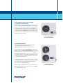
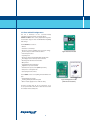
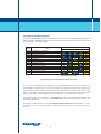
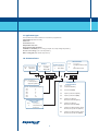
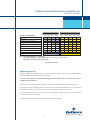
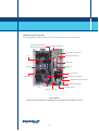
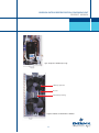
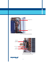
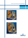
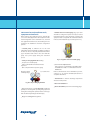
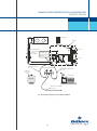
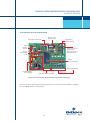
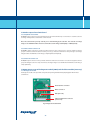
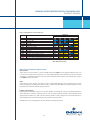
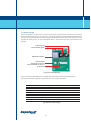
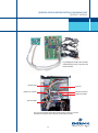
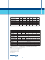
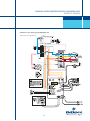
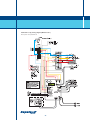
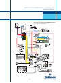
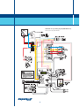
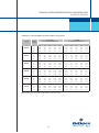
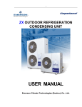
EMERSON
OUTDOOR REFRIGERATION CONDENSING UNIT
PRODUCT MANUAL
CONTENTS
Section Item
1.0
2.0
3.0
4.0
5.0
6.0
7.0
8.0
9.0
10.0
11.0
12.0
13.0
14.0
15.0
16.0
17.0
LIST OF ILLUSTRATIONS
Page No.
Disclaimer
1
Introduction to
the ZX refrigeration condensing unit (CU)
2
2.1 Product description
2.2 SILVER and GOLD configurations
2.3 Control features
2.4 Diagnostic and defrost features
2.5 Advantages
2.6 Emerson condensing unit makes
for exceptional value
2.7 Application types
Nomenclature
8
Receiving your condensing unit
9
Physical layout of the ZX
10
Dimensions and installation clearances
14
Essential commissioning tools and equipment
16
Electrical installation
17
Refrigeration piping installation
17
Start-up-leak checking, evacuation & charging
20
10.1 Initial pressure testing
(by vacuum and nitrogen)
10.2 Leak test
(by refrigerant with nitrogen pressurization)
10.3 Evacuation
10.4 Charging and commissioning
E2 Control and operating features
23
Operation and set-up of the E2 unit controller
25
12.1 Compressor /unit setting
12.2 Compressor motor protection
12.3 Compressor pressure protection
12.4 Compressor discharge temperature protection
12.5 Other inputs to the E2 board
12.6 Other outputs from the E2 board
Operation and set-up of modules
30
13.1 Diagnostic module
13.2 Defrost module
Maintenance
34
Spare parts' list
35
Troubleshooting
37
Addendum:
17.1 General technical data: R22 & R404A
38
17.2 Wiring diagrams
39
17.3 Capacity (kW) & Power (kW)
at 50Hz for refrigerant R22
43
17.4 Capacity (kW) & Power (kW)
at 50 Hz for refrigerant R404A
44
Section Item
Fig.1
Fig.2
Fig.3
Fig.4
Fig.5
Fig.6
Fig.7
Fig.8
Fig.9
Fig.10
Fig.11
Fig.12
Fig 13
Fig 14
Fig.15
Fig.16
Fig 17
Fig 18
Fig 19
Fig 20
Fig 21
Fig 22
Fig 23
Fig 24
Fig 25
ZX Single fan unit (ZX200, ZX300 & ZX400)
ZX Dual fan unit ( ZX 500, ZX600 & ZX 750)
E2 Control board
Defrost module
Diagnostic module
Diagnostics interpretation chart
ZX Nomenclature
ZX 600 TFD (with front panel open to
expose the components)
Compressor chamber (close-up)
Condenser coil and fan motor chamber
Location of fixed pressure switches
Patented liquid injection system
3-Dimensional view - Single fan
3-Dimensional view - Dual fan
Physical dimensions
Four port charging manifold
Electronic vacuum gauge
Commissioning, hook-up
and essential equipment
E2 Unit controller board - layout
and major components
E2 Control reference guide
Diagnostic module details
Defrost module details
Defrost module settings
E2 Board connected to
the modules and sensors
Location of electronics
and electrical components
Page No.
2
2
3
4
4
6
8/9
10
11
11
12
12
13
13
15
16
16
19
25
28/29
30
32
32
33
33
EMERSON OUTDOOR REFRIGERATION CONDENSING UNIT
PRODUCT MANUAL
1.0 Disclaimer
Thank you for purchasing the Emerson scroll refrigeration condensing unit. We hope that you will find this product
meeting your refrigeration needs efficiently and effectively. Please read through this Product Manual thoroughly to
familiarize yourself with the value-added features of this product and how to use it optimally to suit your needs.
Please do read the following information carefully before proceeding with the rest of the Manual.
The Emerson ZX outdoor refrigeration condensing units should only be installed by suitably qualified and
experienced refrigeration technicians. No responsibility can be accepted for damage caused by inexperienced or
inadequately trained site technicians or improper system design.
All installation instructions & procedures described in this Manual are recommendations based on what are
considered to be good refrigeration trade practices (as applied to this particular product.) The installation contractor
may prefer to use variations to these recommendations; however, it is to be noted that the methods described in
this manual represent the very minimum required to avoid any subsequent warranty claims for this equipment or its
component parts. These instructions do not cover the fundamentals of good electricity or refrigeration practice and
are therefore intended for use only by qualified and/or experienced personnel as mentioned above or those
technicians certified by us.
These instructions are general in nature for this family of products (ZX) and due to our policy of continuous
improvement some of the features/details may not apply to the unit you are installing. If in doubt, please consult
your local sales office, quoting unit Model and Serial number as shown on each unit nameplate. In case of ambiguity,
the wiring diagram supplied with each unit takes precedence over the diagram in this Manual .
1
2.0 Introduction to the Emerson outdoor
refrigeration condensing unit
Emerson Climate Technologies, a Division of Emerson Electric
Ltd. launched the ZX Condensing Unit (CU), a new refrigeration
product to the Asian market to primarily meet the demands of
the food retail services and logistics sector. The ZX CU is an aircooled, outdoor-type refrigeration condensing unit that uses
patented Copeland scroll technology as the main driver and has
electronic protection, diagnostics and communication features
in-built into the compact chassis.
Fig1. Single Fan Unit
( ZX 200, ZX 300 & ZX 400 )
2.1 Product Description
The application range of the Emerson ZX CU is between:
* -15 C to 5C Evaporating Temperature and
* 27 C and 43 C Ambient (without Fan Speed Control).
This CU is released with both R22 and R404A refrigerants. The
single fan units are ZX 200, ZX 300 and ZX 400 (2, 3 and 4 hp
nominal ARI Medium Temperature) and the dual fan units are
ZX 500, ZX 600 and ZX 750 (5,6 and 7.5 hp nominal ARI MT).
These CUs are built for robust outdoor applications and have
excellent wall-mounting capability and aesthetics, much like air
conditioning split outdoor units.
The Copeland brand scroll compressors that power these CUs
are manufactured in Asia, ensuring a low-cost high-technology
approach to suit the needs of demanding Asian customers.
The ZX is therefore a very affordable unit.
When the large coil- small fan design is combined with in-built
(but optional) fan speed control, the ZX is one of the quietest
refrigeration CUs in the market.
2
Fig 2. Dual Fan Unit
( ZX 500, ZX 600 & ZX 750 )
EMERSON OUTDOOR REFRIGERATION CONDENSING UNIT
PRODUCT MANUAL
State-of-the-art electronics provide protection, diagnostics and communication features in the ZX. These features are
controlled by the custom-designed, custom-built E2 Electronics Control Board. The E2 provides:
* base control functions related to the system temperature controller, defrost, evaporator fan control etc.
* compressor protection e.g. current overload, voltage imbalance, anti - phase reversal etc.
* liquid injection control which keeps the discharge head temperature within safe and acceptable limits
* self- diagnostics (optional) which receives operating status, alarm and warning from the E2 micro controller unit and
displays these for easy and rapid trouble-shooting and maintenance
* communication capability that allows the E2 to dial out to specified numbers via a dialer module. Development is in
progress to integrate the E2 Board with the CPC Einstein E2 control and monitoring system which will then enable the
ZX to be part of an entire "Emerson Climate Technologies Integrated Store Solution".
Fig 3. The E2 Control Board
3
2.2 Silver and Gold Configuration
The ZX is marketed in two customer-friendly
configurations that carry their own unique labels:
SILVER and GOLD. This is clearly explained through the
nomenclature diagram and the Bill-Of-Material (BOM)
table in Fig 7.
The ZX SILVER CU consists of:
* Chassis
* Condenser coil and fan/s
* Electronic control board (E2 Board + protective casing)
* The ZX compressor with a crankcase heater
* Vertical liquid receiver
* Liquid injection
* Electronic expansion valve (EXV) with capillary tube
* Fixed high-pressure and low pressure switches
* Discharge line thermistor and lead wire
* Oil separator
* Liquid line filter drier/sight glass
* Adjustable low pressure switch
* Condenser fan speed control (BOM dependent)
* Compressor sound jacket and
* Suction/liquid service valves.
The ZX GOLD consists of everything in the SILVER version
plus:
* In-built diagnostic module
* Isolating switch (Circuit Breaker) and
* Buzzer module (supplied loose without cable)
A Defrost module (Fig 4) can be purchased as an
accessory with either of the above units and can be built
in to the CU at the assembly line.
4
Fig 4. The Defrost module
Fig 5. The Diagnostic module
(with the remote buzzer)
EMERSON OUTDOOR REFRIGERATION CONDENSING UNIT
PRODUCT MANUAL
2.3 Control Features
The ZX CU Control System evolves around the E2 Board
and one of its primary functions is control of the
Automatic Liquid Injection system.
The liquid injection method is a unique and Emersonpatented technology. This technology ensures that the
ZX compressor operates within a safe envelope. The
Injection is based on measurement and relay of the
scroll discharge temperature to the E2 board which
has a built-in algorithm that converts this data into a
specific digital signal. This digital signal is sent to a
stepper motor driving an Electronic Expansion Valve
(EXV). The EXV accordingly supplies sufficient liquid
refrigerant to keep the compressor head temperature
within safe limits.
Other compressor protection features are:
* Compressor phase reversal
(Scroll compressor will not compress in reverse )
* Voltage imbalance protection
* Loss of phase protection
* Motor current overload
(Built-in and therefore no external current protection
is required ),
* Non-adjustable high and low pressure switches
(Automatic reset for a specific number of trips, and
lockout thereafter [for high pressure only] that
requires manual restart)
* Liquid floodback protection
(measurement of discharge superheat to predict
liquid floodback)
* Fresh start programs
(to ensure safe start-up after long period of inactivity)
* Crankcase heater
(energized when compressor stops)
5
With the highly useful condenser fan speed control
function, the operating range can be reduced to -30oC.
This is useful at start-up and operation at extremely
low ambient conditions. The fan speed control option
is recommended when the ambient temperature falls
below 25oC. At temperatures below 10oC, fan speed
control is no more an option, but an absolute
necessity.
The base control function is for connection of
optional/ customer applied functions such as:
* Temperature controller or thermostat
* Electric defrost heater
* Contactor
* Evaporator fan contactor
* Output for dialer
* Compatibility with CPC's Einstein control &
monitoring
system (future plan)
2.4 Diagnostic and defrost features
The Diagnostic module (Optional) is also installed within the chassis and has 5 LEDs (Light Emitting Diodes ) that can
either be ON, OFF or BLINKING. The tabulation of the 5 LEDs with the 3 possible status provides a bird's eye-view of
the system status as shown in Fig 6 below:
Status
Normal
Normal
Normal
Normal
Normal
Fault
Fault
Fault
Fault
Fault
Fault
Fault
Fault
Warning
Fault
LED Status
Event
Unit OFF/Phase 'U' or 'N' missing
Power ON
Compressor ON
Fresh Start/Normal Start
Defrost ON
DLT Overlimit
Ambient sensor failure
MCT sensor failure
DLT Thermistor failure
HP Cut Out
Compressor Over Current
Compressor Incorrect Phase sequence
Compressor Voltage Imbalance
System Liquid Floodback
Compressor about to turn ON & Ambient sensor failure
D1
Off
Off
Off
Off
Off
Blink
Blink
Blink
Blink
Blink
Blink
Blink
Blink
Blink
Off
D2
Off
Off
Off
Off
Off
On
On
Off
Off
Off
On
Blink
On
On
Blink
D3
Off
Off
Off
Off
Blink
Blink
Off
On
Off
On
On
On
Blink
On
Off
D4
Off
Off
On
Blink
Off
Off
On
On
On
Off
Off
Off
Off
Blink
Blink
D5
Off
On
On
On
On
On
On
On
On
On
On
On
On
On
On
DLT Discharge Line Temperature
MCT Mid Coil Temperature
Fig 6. The Diagnostics module LED status interpretation table
For e.g., if the 5 LEDs display as follows: D1 (blink), D2 (on), D3 (on), D4 (blink ), D5 (on), then it is an indication of a
potential liquid floodback situation. In such a serious situation, the refrigeration technician who responds to the
diagnostic alarm would save valuable time since the LED display enables him to get straight down to the root cause
of the issue and evolve a speedy diagnosis: an iced-up evaporator due to defrost malfunction, faulty evaporator fan,
faulty or oversized TXV or even wrong evaporator selection (to high ΔT for a low temperature application).
The diagnostic module can be connected to a remote buzzer which alerts the recipient through an alarm to any
potential issue with the CU.
The ZX defrost module (optional accessory) is time-initiated and time-terminated with manual button to override
the settings i.e. to stop or start defrost. A remote, manual defrost button can also be connected to the defrost
module.
6
EMERSON OUTDOOR REFRIGERATION CONDENSING UNIT
PRODUCT MANUAL
2.5 Advantages
Some key advantages that the Emerson ZX CU has over
similar units in the market are:
* It is extremely affordable and has a very low noise level.
* It is cost effective and more affordable: it comes with
in-built state-of-the-art technology such as the E2
Board with several programmed algorithms and the
diagnostic module.
* The Copeland brand compliant scroll which has a low
noise level (60 dBA at 1m), very low oil carryover
(About 0.2 % oil circulation rate compared to the 2-3%
in systems using reciprocating compressors)
* The radial compliance of the scroll set which helps to
withstand substantial liquid floodback;and
High
efficiency ( EER between 2.4 - 2.75 @ ARI MT Rating)
*
2.6 The ZX Provides exceptional
customer value
To our customers, the features of the ZX CU translate
into some exceptional values:
Energy saving
More efficient than hermetic and semi-hermetic
reciprocating & rotary compressors
Service saving
The diagnostic module can pin-point the issue,
reducing valuable service time and downtime.
Fan speed control
Low sound level and lower energy consumption
Ventilation
Easy to retrofit for discharge air extraction.
Machine room saving
Eliminate wasteful space - mount the unit on the wall
The following explains why the ZX is more energy
efficient:
Scroll compressor
* Large suction and discharge ports
Reduces pressure losses incurred in suction and
discharge processes: physical separation of these
ports reduces heat transfer to the suction gas.
* No leakage past piston rings
* Absence of valves and re-expansion volumes:
continuous compression and high volumetric
efficiency
* Flatter capacity curve (than reciprocating
compressor systems) over wide ambient range
Condenser fan-coil design
* Small fan
large coil combination
Condenser fan speed control (optional)
Reduced food spoilage
High unit reliability and early warning/ diagnostics
capabilities that reduce the chances of food spoilage.
Infrequent compressor replacement
Better ability to withstand prolonged liquid floodback
& good discharge temperature control
Great aesthetics
Can be installed outdoor, much like a split air
conditioning outdoor unit.
Built-in electrical fuses, contactors and connectors
No switchboard requirement; neat, compact and
space-saving feature.
7
Built-in delay times in the E2 board (reduces total
run time)
Lower night loads
2.7 Application Types
The versatile Emerson ZX is suitable for a wide variety of applications:
Supermarkets (medium to small)
Cold rooms
Convenience stores
Independent cold rooms
Fast food chains and restaurants
Small flake ice machines (250 to 750 kg per day @ -15 oC evaporating temperature)
Process room cooling (10 oC room temperature)
Water cooling (PHE/Tube-in-tube evaporators)
3.0 ZX Nomenclature
Code
ZX
Description
Unit Family
Oil Type
Code
Description
E
Ester Oil
0
Mineral Oil
Compressor Motor
Code Description
T
Three Phase
Code Description
L
Low Temperature
Application (Future)
Code
020
030
040
050
060
075
Num.
300
Nominal Capacity(HP)
2
3
4
5
6
7.5
Compressor Motor
Protection
Code
Description
F
Internal Inherent
Protection
8
Code
D
Electrical Codes
Description
380V/420V 3 Phase 50Hz
or
440V 3 Phase 60 Hz
Bill Of Material
Product Variations
Description
standard unit(China)
350
Standard Unit(ROA)
301
w/Fan Speed Controls(China)
350
w/Fan Speed Controls(ROA)
400
w/Diagnostic Module,
Buzzer,Circuit Breaker(China)
450
w/Diagnostic Module,
Buzzer,Circuit Breaker(ROA)
401
w/Diagnostic Module, Buzzer,Circuit
Breaker,Fan Speed Controls(China)
451
w/Diagnostic Module, Buzzer,Circuit
Breaker,Fan Speed Controls(ROA)
EMERSON OUTDOOR REFRIGERATION CONDENSING UNIT
PRODUCT MANUAL
Silver
Bill of Material (BOM) Numbers
300
350
301
Gold
351
400
450
401
451
420
Liquid Line Filter Driver & Liquid Sight Glass
Oil Separator
Adjustable Low Pressure Switch
Fan Speed Controller
Diagnostic Module
Romote Buzzer
Circuit Breaker (Isolating Switch)
Compressor Sound Jacket
Accessory
Defrost Module
Accessory
Note: BOM 300,301,400,401 is for China Only
BOM 350,351,450,451 is for Rest OF Asia only ( excluding Australia and New Zealand)
BOM 420 is for Australia and New Zealand only
Fig 7. ZX Nomenclature
4.0 Receiving your unit
All units are shipped with a holding charge of dry nitrogen inside at a low but positive pressure. Suitable labelling is
prominently displayed on both the unit and the packaging.
Caution! It is very important to check that this holding pressure exists at the time you receive the unit from us or
our authorized representatives.
Several Schraeder type connections are provided for convenience in checking the integrity of the holding charge.
If, after checking, you find the holding charge non-existent or low, you should immediately inform us or our authorized
representative. Failure to do so could void your claim for other related system faults at a later period.
It is also advisable to inspect the rest of the unit for obvious physical damage and inform us or our authorized
representative in case any is discovered.
Transit damage is essentially an insurance claim and not covered under warranty.
9
5.0 Physical layout of the unit
The following illustration identifies the major components and where these are located in the ZX unit.
Diagnostic module (Gold)
Defrost module (optional)
Isolating switch(Gold)
E2 Electronic control board
Fan
Electrical terminal block
Oil separator
Receiver
Sight-glass
Scroll compressor
Suction line service valve
Condenser coil
Adjustable low pressure switch
Liquid line service valve
Filter drier
Crankcase heater
Receiver outlet valve
Fig 8. ZX 600 TFD
(components inside your Emerson condensing unit, as viewed when the front panel is removed)
10
EMERSON OUTDOOR REFRIGERATION CONDENSING UNIT
PRODUCT MANUAL
Fig 9. Compressor chamber (close-up)
3 Blade propeller fan
Receiver
Fan bracket/mounting
Fig 10. Condenser coil and fan motor chamber
11
Fixed HP switch
Fixed LP switch
Fig 11. Location of fixed pressure switches
Electronic
expansion
injection valve
Injection line
Injection
capillary tubing
Fig 12 Patented liquid injection system
12
EMERSON OUTDOOR REFRIGERATION CONDENSING UNIT
PRODUCT MANUAL
Fig 13. 3-D view of single fan ZX
(not to scale: not meant to be used for dimensions or installation)
Fig 14. 3-D view of dual fan ZX
(not to scale: not meant to be used for dimensions or installation)
13
6.0 Dimensions and installation clearances
Fig 15. shows the overall dimensions of the unit. It is recommended that a clearance of 300 mm from the wall (or the
next unit) be maintained from the unit's left and rear panel; whereas a clearance of 500 mm should be maintained
from the unit's right, top and front panels (as viewed from the front of the unit). Both service access and airflow have
been considered in making these recommendations.
Where multiple units are to be installed in the same location, the contractor needs to consider each individual case
carefully. There can be many variations of unit quantities and available space and this manual does not cover all such
possible options. But in general, air by-pass around each condenser and between each unit should be avoided at all
times.
Ideally, the unit should be mounted level on a solid concrete slab with rubber strips between unit base and concrete.
However the condensing unit has also been designed for wall mounting on suitable brackets. In this case, apart from
the spatial guidelines given above, an additional consideration is the possible air recycling if units are stacked above
and below each other.
Another factor to consider in finding a good installation site is the direction of the prevailing wind. For example, if the
air leaving from the condenser faces the prevailing wind, the air flow through the condenser can be impeded, causing
high condensing temperatures and ultimately resulting in reducing the life of the unit. A baffle is one remedy for this
situation.
Caution! The unit should never be installed adjacent to a dust source (dirt road). External fouling of the condenser
fins also leads to high condensing temperatures and will reduce the life of the unit.
14
EMERSON OUTDOOR REFRIGERATION CONDENSING UNIT
PRODUCT MANUAL
950
1029
112
213
91
173
110
840
388
ZX0200, 0300, 0400 (Single fan units)
580
424
110
1242
388
ZX0500, 0600, 0750 (Dual fan units)
950
1029
213
112
91
173
580
424
Fig. 15 Physical dimensions
15
7.0 Essential service/installation tools,
equipment and materials
Before start-up, the technician needs to assemble the
correct tools and equipment for the task. Apart from the
normal refrigeration service technician tools, electrical
test equipment and hand tools, the following items are
essential for the installation of hermetic refrigeration
systems:
* Reliable electronic vacuum gauge. (Fig. 17) A clean
and leak-free refrigeration system can only be assured
if the initial vacuum is deep and holds on testing. This
equipment must comply with the standards indicated
in the recommended start-up procedures (Section 9.)
* Vacuum pump of sufficient size for the total
refrigeration system and capable of pulling a vacuum of
at least 100 microns. This pump should be fitted with a
proper vacuum breaker valve in the event that this
pump loses power supply during the evacuation
process
Fig 17. A popular electronic vacuum gauge
* A four port charging manifold including:
. A 3/8" hose to vacuum pump
. All hoses fitted with removable Schraeder
depressors
. One compound and one pressure gauge
All of this equipment should be leak-free, accurate and
reliable (See Fig 16).
* Clean and new compressor oil.
. Witco LP 200 is recommended for the ZX R22 units
. Mobil EAL Artic 22CC is recommended for the ZX
R404A units
If the recommended oils are not available in your area,
contact us or our nearest distributor/wholesaler for
acceptable alternatives
* Thermometer to measure discharge temperature
and suction temperature
Fig 16. Four port charging manifold
* Clean and new (not recycled) refrigerant of sufficient
quantity for the refrigerant operating change plus leak
testing. Note: Refrigerant cylinders must be of the type
that can deliver liquid refrigerant until empty.
* Oxygen-free nitrogen and regulators.
16
* Electronic leak detector
* Electrical insulation performance measuring gauge.
EMERSON OUTDOOR REFRIGERATION CONDENSING UNIT
PRODUCT MANUAL
8.0 Electrical installation
Caution! This work should be carried out only by suitably qualified electricians.
Please check the unit nameplate and run ample capacity three phase and single phase (including neutral and earth
wiring) to each unit. A suitably rated isolating switch (this is also an option that could be selected) should be fitted
immediately adjacent to each unit .This is not only good practice from a safety standpoint, but is usually a mandatory
requirement for most electrical supply authorities today. All incoming phase lines are to be suitably fused at the subboard to protect the installed wiring and the unit.
9.0 Refrigeration piping installation
Caution! This work should be carried out only by suitably qualified refrigeration technicians.
A good understanding of modern scroll compressor hermetic systems is also essential when carrying out this work particularly for initial evacuation and charging procedures.
Caution: All interconnecting piping should be of refrigeration grade, clean, dehydrated and remain capped at both
ends until installation. During installation, if the system is left unattended for any reasonable period of time (even
2 hours), the pipes should be re-capped to prevent moisture and contaminant from entering the system.
It is advisable to insulate both the suction and liquid interconnecting piping between the ZX unit and the evaporator.
Usually the suction line is insulated, but the liquid line is not. However, the liquid line can pick up additional heat from
the ambient and adversely affect the sub-cooling desirable for the liquid refrigerant before it enters the expansion
valve.
Pipe sizing should not only ensure optimum performance and good oil return, but also take into account the full
capacity range through which this particular unit will operate.
Pipe runs should be kept as short as possible, using the minimum number of directional changes. Use large radius
bends and avoid trapping of oil and refrigerant. This is particularly important for the suction line. The suction line should
ideally slope gently toward the unit. Recommended slope is 1/200~1/250. P-traps, double risers and reduced pipe
diameters may be required for suction lines where long vertical risers cannot be avoided.
17
All pipes should be adequately supported to prevent sagging which can also create oil traps. The recommended
support distance is as below:
Tube size
Maximum distance between two supports (m)
12.7mm (1/2 inch)
1.20
16.0mm (5/8 inch)
1.50
22.0mm (7/8 inch)
1.85
28.5mm (11/8 inch)
2.20
The solenoid valve should be installed close to the indoor TXV.
To avoid oxidation from taking place inside the tube during brazing, charge no more than 0.1MPa nitrogen through
the tube when brazing the joint.
There are several books on good trade practices for refrigeration piping available. The above points are intended as
good practical guidelines and it is not our intention to repeat the many variations in this manual.
Warning!
Do not assume that the service connection sizes on the unit (at the service valves) are in fact the correct sizes to run
your interconnecting refrigeration pipes. The service valve sizes have been selected for convenience of installation
and in some cases, as in larger units, these may be too small. However, for the very short pipe run within our units,
these service connection sizes are adequate. All interconnecting piping should be sized to satisfy the duty required.
18
EMERSON OUTDOOR REFRIGERATION CONDENSING UNIT
PRODUCT MANUAL
ATMS
5000
1500
GOOD
Vacuum gauge
VG-60
700
O
N
O
F
F
1000
400
300
200
50
MICRONS
VACUUM GAUGE
ZX UNIT
Supco
100
Evaporator
Expansion valve
Shraeder conn.
4
LL Solenoid valve
AIRFLOW
HP
Interconnecting
Note: Remove both
Piping
Schraeder cores
(Insulated)
before evacuation &
charging.
MP
4
AIRFLOW
LP
Suction service hose.
size = 1/4"
Clean (new)
refrigerant
4 port Gauge Manifold
Liquid/discharge service hose
size = 1/4"
H
L
Vacuum Pump
Refrigerant
Main service connection
size = 3/8"
Fig. 18 Commissioning hook-up & essential equipment
19
10.0 Leak checking and evacuation
(See Fig.18 )
The following assumes that the installation contractor
has certified the condensing unit to be leak-free on
arrival (refer to Section 4.0) - this is important to verify
before proceeding with the following. Leak checking is
particularly important for field-connected systems.
Typically, field systems lose as much as 20-30% of their
refrigeration charge annually. This is not only an
unnecessary expense but also damaging to the
environment.
Compressor oil can be lost at the same time as
refrigerant and eventually lead to compressor failure.
(The time spent on leak testing will eventually reduce
the time you need to spend on the evacuation
process).
Ensure that all service valves are open during the leak
checking process. It is now important to re-check all
joints within the unit as well as the external joints
created. Since we are aiming at a high degree of
vacuum in the next process, the unit must be leak-free
first.
10.1 Initial pressure testing
(by vacuum and nitrogen)
Step-by-step:
* Use a 4-port gauge manifold with 3/8" hose and
connections to the vacuum pump. The vacuum gauge
does not have to be connected for this part of the
process.
* Then connect gauge lines to both ZX unit service
valves.
* In order to remove any non-condensable that may
have entered the system during installation, follow these
steps: Start the vacuum pump. The liquid line solenoid
should be energized at this point, the cabinet
(evaporator) fans run and compressor crankcase heaters
are energized. This will involve powering up the unit so
it is important to disconnect the live feed wire to the
compressor contactor (so the compressor cannot run
and the crankcase heaters can be energized).
20
* Now open both valves on the manifold and then open
the main vacuum valve on the pump. Run the system
until the vacuum level is at around 0.85 bar (as read on
the manifold suction gauge.)
* Shut off the main vacuum pump valve. Check for
vacuum rise - use the manifold compound gauge. A rise
would indicate a large leak.
* If vacuum holds for 10 minutes, break vacuum with
nitrogen and pressurize to 10 bar. Check for leaks by
feel and sound. (This step is to look for large leaks only.)
Repair leakage if leak is detected.
Proceed to step 10.2.
10.2 Leak test
(by refrigerant with nitrogen
pressurization)
Step-by step:
* Release nitrogen from system, start vacuum pump
and open main pump valve.
* Then evacuate for a second time to 0.85 bar (as read
on the manifold gauge.)
* Break this vacuum with R22, after shutting off the
main pump valve and then stopping the pump.
* Allow the system to equalize with R22 cylinder
pressure (to at least 1.7 bar)
* Then remove the cylinder and increase system
pressure, using nitrogen to 15 bar.
* Leak test all joints inside and outside the unit (ie., the
complete system) using at least a halide leak detector
or preferably an electronic leak detector.
* Repeat all previous steps in this section until the
system is completely leak-free.
* Release all pressure from the system, remove the
nitrogen connections and reconnect manifold service
hose to vacuum pump main valve.
Proceed to step 10.3
EMERSON OUTDOOR REFRIGERATION CONDENSING UNIT
PRODUCT MANUAL
10.3 Evacuation
Note that the following procedure is based upon
achieving an actual system vacuum standard and it is
NOT TIME DEPENDENT!
Step-by-step:
* Check suction capability of the vacuum pump with a
gauge before commencing evacuation process. The
vacuum pump must be rated to achieve a vacuum level
of at least 300 microns.
* Connect the vacuum gauge to the system. We have
included a convenient point for this on the unit (See
Fig.7).
* It is recommended to carry out the evacuation
process thrice as detailed below:
* Start the vacuum pump and then open the main
valve. It is assumed that the items mentioned in Section
9.1 are still energized and the compressor cannot start
Caution:
Ensure that the vacuum pump cannot be switched
off during evacuation - otherwise the pump may
lose its lubrication oil to the system and
contaminate it.
Therefore the pump must have a Vacuum Breaker
fitted to it.
21
* Step1 evacuation: Bring system down to 1500
microns and then break the vacuum to 2 psig with the
same refrigerant.
* Step 2 evacuation: Same as in Step 1.
* Step 3 evacuation: Leave the pump running while
checking the vacuum regularly. The target system
vacuum is 500 microns.
* Once the target vacuum level is reached, the quality
of the vacuum within the system must be tested. This
is achieved by shutting off the main pump valve,
allowing the internal system pressure to rise and
recording the time taken for the vacuum to rise by no
more than 300 microns within 30 minutes. (ie., to 100
microns.)
This process is only complete once the vacuum quality
is achieved. Then close the two manifold valves
tightly. Close the pump main valve, switch off and
remove the vacuum pump.
Proceed to step 10.4
10.4 Charging and commissioning
IMPORTANT!
TO BE CLEARLY UNDERSTOOD PRIOR TO RUNNING
ANY SCROLL COMPRESSOR!
It is important to realize that the scroll compressor
design requires system charging as quickly as
possible - with liquid refrigerant into the liquid line.
This is to avoid running the compressor when there is
an insufficient volume of suction gas to cool not only
the motor, but also the rotating scrolls. (Temperature
builds up very quickly in the scrolls if this is not done!)
DO NOT CHARGE VAPOR IN THE SCROLL
COMPRESSOR!
It therefore follows that the suction service valve must
not be fully closed at any time when the compressor is
running. To do so would cause compressor duress as
explained above. This valve is provided for ease of
connection and for fitting the service gauges without
removing the unit panel.
Step-by-step:
* Ensure that there is no power supply to the unit. The
liquid line solenoid needs to be kept open for the
charging process and it may require a temporary power
feed. At this point it is acceptable to leave the crankcase
heater off.
* Connect the refrigerant cylinder to main service hose
and purge line at the manifold end.
* Then invert the refrigerant cylinder if necessary to
ensure only liquid refrigerant can be charged into the
system. This will be charged through the high-pressure
side of the manifold and liquid service valve.
* The refrigerant cylinder should be weighed at this
point to be able to record the final refrigerant charge
attained. Note that the standard receiver holds
approximately 7.6kg of R22 (at 32oC when it is 80% full).
22
* Now open the liquid service valve (off the back seat).
At ambient, with a good vacuum in the system and the
refrigerant cylinder inverted, you should not have to
run the compressor at all.
* In cooler ambient, it may be necessary to run the
compressor in order to complete the charging process.
It is advisable to do this after the previous step,
allowing the system/bottle pressures to equalize and
almost fully closing the receiver liquid outlet valve
(front seat).
* The compressor can then be started, and the unit
continues to be charged (with liquid refrigerant
through the liquid service valve). The quantity of
charge should always be measured.
* Turn off the unit and open the receiver liquid outlet
valve (which was almost fully closed earlier).
* The system needs to be operated down to its
designated evaporating temperature before you can be
sure that the charge is correct. It is at this point that the
normal refrigeration operational checks can be carried
out-such as checking the liquid line sight-glass for
violent bubbles and the operating pressures.
* In the event that the system is still short of
refrigerant, repeat the last 4 steps.
EMERSON OUTDOOR REFRIGERATION CONDENSING UNIT
PRODUCT MANUAL
11.0 E2 control and operating features
The function of the E2 is to react to the ON/OFF signals it receives from various devices (e.g., thermostat) to operate
and protect the ZX unit. The E2 control panel is fitted as standard for the SILVER and GOLD and has been developed to
work in tandem with the ZX compressor to provide the following control and protection systems:
Automatic liquid injection: The E2 automatically injects cool liquid refrigerant into the suction line of the ZX scroll
compressor to reduce discharge temperatures generated when the unit operates at increasing compression ratios. The
E2 controller reacts automatically to a thermistor embedded in a pocket inserted into the top of the ZX compressor.
The controller converts this into a signal for the linear stepper motor (that drives the liquid injection valve) to a position
that enables the compressor to continue operating within its safe envelope. This advanced control strategy extends the
operating range and is not normally associated with a standard refrigeration condensing unit of this size - making
this feature a highly advantageous differentiation from other refrigeration CUs in the market.
The E2 is also the base controller for the connection of many Emerson-supplied and customer applied functions such
as:
* Main refrigeration load controller ( or thermostat)
* Evaporator electric defrost heater contactor
* Evaporator fan contactor
* Fan speed control ( found in some SILVER and all GOLD versions ) This option automatically controls fan speed and is
useful where low ambient temperatures are experienced- such as might cause a loss of case/cool room temperatures
and control. Low ambient temperatures reduce the condensing pressures to such low levels that there is insufficient
pressure drop across the expansion device to force the liquid refrigerant through the orifice at the evaporator. As we
know, liquid refrigerant being forced through the orifice is what causes part flashing of the refrigerant and brings it closer to
the designated boundaries of evaporating pressure and temperature. Control is via the E2 board, a modified E2 microcontroller- with the in-built fan control logic and two additional sensors (condenser coil and ambient sensors).
* Diagnostic module (only with GOLD version) The option provides the ZX with a self diagnostic function, signaling
individual component failure in three ways:
(a) visible LED combination
(b) remote audible buzzer
(c) dialer connection for the purpose of sending a common fault signal through
a telephone service to a remote location.
Details on how to obtain diagnostic information from the five module LEDs located on this module was explained in
Section 2.4 and Fig 6. The module is mounted below the E2 Board and the LEDs can be easily seen with the front
compressor compartment panel removed (Fig 24).
* Defrost control module (accessory) This option provides a basic, time-initiated and time-terminated defrost control
with additional manual override (push-button). Its location is shown in Fig 24.
23
Compressor phase reversal
ensures that the compressor runs only in one direction - a necessity for a compliant scroll compressor to compress and
pump refrigerant. Reset is automatically set to the correct phase rotation of the compressor.
Voltage protection
ensures that the compressor only operates within the very wide design voltage tolerance of the three-phase motor.
Motor current overload protection is provided (also via the E2) eliminating the need for external current protection
for the compressor motor.
Fixed low and high-pressure switches: These are non-adjustable protection devices that prevent the compressor
from operating outside its designated envelope of safe evaporating and condensing pressures. Reset is automatic for a
set number of trips: the unit will lock out thereafter and require manual restart. This latter feature is important to prevent
the ZX unit cycling under these controls for a long period of time.
A crankcase heater is wired through a normally closed contact of the compressor contactor in the usual manner,
becoming energized whenever the compressor cycles off.
In addition to the above, the ZX has all the following components and features assembled into the SILVER and GOLD
versions:
* Liquid line assembly (filter drier and sight glass/moisture indicator)
* Oil separator
* Coated condenser fins ( for light-medium seaside/marine conditions)
* Adjustable LP switch for low pressure pump-down control
24
EMERSON OUTDOOR REFRIGERATION CONDENSING UNIT
PRODUCT MANUAL
12.0 Operation & set-up of the E2 board
Microprocessor
Controller Unit
Temperature Sensor Inputs
High and Low
Pressure Control
Liquid
Injection
Control
Compressor Selector
Rotary Switch
(not to be tampered
with by the User)
Current
Abnormality
Coils
3 Phase
Protection Module
High Voltage Output
Digital Switching
Power Supply
Power and Thermostat Input
Fig. 19 E2 unit control board - layout and major components (previous page)
Please refer to Fig.18 together with the ZX wiring diagram (for the connection points) in Addendum 17.2 (identify
the correct BOM first) at the end of this manual.
25
12.1 Compressor/unit setting
12.3 Compressor pressure protection
Each ZX unit model has a unique ZX compressor model
and this has to be programmed in the set-up of the E2
controller. For this purpose a compressor rotary switch
is located near the top right hand corner of the E2
board (see the diagram in the previous page). This is a
factory setting and should not be re-set thereafter. Any
tampering with this compressor rotary switch will result
in warranty claims becoming null and void.
12.3.1 High pressure
A sensor is registered by the E2. The sensing device is a
non-adjustable, low voltage pressure switch that will
open in the event of an abnormally high discharge
pressure (above 2.8Mpa).
* The unit will stop and then restart automatically after a
3-minute delay.
* After 5 successive HP cut-outs over a 1-hour time
span, the unit will lock-out.
* Unit reset procedure is as described in the previous
table (above).
12.2 Compressor motor protection
The E2 protects the compressor motor against the
following:
* Over current
* Voltage imbalance (between phases)
* Loss of any one phase
* Incorrect phase rotation
If the compressor motor current exceeds a pre-defined
current limit (non-adjustable), then the E2 shuts down
the unit and generates an error signal to the LEDs on
the board.
For this function to operate, two of the main phase
supply lines to the compressor (compressor via the
contactor) are routed through the current
abnormality coils.
[Note: Unit lock-out can activate a telephone dialer and
buzzer plus signal on the LEDs of the diagnostic module
(in the GOLD version)]
12.3.2 Low pressure
In a method similar to that of the high pressure sensor,
the E2 registers the switching action of a nonadjustable, low voltage pressure switch that will open
in the event of an abnormally low suction pressure
(below 0.1Mpa).
* The unit will stop and then restart automatically after a
3-minute delay.
* There is NO lock-out for this switch.
* Unit reset procedure is as described in the table
above.
[Note: Unit lock-out can activate a telephone dialer and
buzzer plus signal on the LED's of the diagnostic
module (in the GOLD version)]
To satisfy the low pressure pump-down control
function, an adjustable low pressure switch is fitted in
the unit.
26
EMERSON OUTDOOR REFRIGERATION CONDENSING UNIT
PRODUCT MANUAL
12.4 Compressor discharge temperature
protection
Abnormally high discharge line temperature can
damage the scroll sets as well as the compressor
motor. The ZX employs a patented liquid injection
process that injects liquid refrigerant into the suction
line as previously described.
Activation of the liquid injection valve is in response to
a clip-on thermistor located at the discharge line of the
ZX scroll compressor. The E2 takes this signal and
converts it into a signal to the stepper motor of the
injection valve, opening the valve linearly in response
to increasing discharge temperatures and injecting
liquid refrigerant directly into the suction line,
reducing the discharge temperature. The discharge
temperature setting that triggers this liquid injection
operation is set so as to prevent the high temperatures
that cause the lubricant to lose viscosity, resulting in
compressor mechanical failure.
12.5 Other inputs to the E2 board
12.5.1 Customer supplied control (thermostat)
The E2 accepts a normal 220 volt AC input ON/OFF
signal (such as the switching action of a normal
commercial thermostat) and relays a similar action as
an output to the compressor contactor (refer to the
wiring diagram in the Addendum section) in the case
of thermostat- controlled system. If the system is
controlled by low pressure cut-out for a multiple
evaporator system and/or pump-down system, the E2
accepts the signal directly from an adjustable low
pressure switch.
12.5.2 Case temperature thermistor
An alternative method of system temperature control
can be used. The E2 accepts an input from a common
commercial thermistor. This sensing device is fixed
inside the indoor load (e.g. refrigerated display case). The
sensor has a range of between -40 to+80oC and normally
operates in the range of -10 to +3oC. The maximum
allowed length for the sensor cable is 10 meters. In this
instance, the defrost module (accessory) can be
combined to provide a cost effective case-control
package.
Fig 20 below explains how the E2 control board reacts
to each failure/Incident and the appropriate reset
procedures. It also shows the respective control
settings.
27
Fig 20 . E2 Control reference guide
Failure/Incident Type
E2 Reaction
(E2 event in brackets & italics)
Setting
High pressure
cut-out
Contact Open 2.8
±0.1Mpa
Contact Close 2.1
±0.07Mpa
Execute STOP program and after 3 minutes run
normal START program to restart the CU. HP error
signal is set to the 6th request for reset and system
will be locked out. The Diagnostic LEDs will light-up.
(HP Cut-out)
Low pressure
cut-out
Contact Open 0.1
±0.05Mpa
Contact Close 0.2
±0.05Mpa
Execute STOP program and after 3 minutes run
normal START program to restart the CU
Discharge
Gas Overheat
Different settings
for different
compressors
Execute STOP program and after 3 minutes run
normal START program to restart the CU. DLT error
signal is set to the 6th request for reset and system
will be locked out. The Diagnostic LEDs will lightup.(DLT Overlimit)
Discharge Line
Sensor Failure
Different setting
for different
compressors
If sensor is under-range after 3 minutes of the
compressor start-up, sensor failure is confirmed
and the diagnostic LEDs will light-up.
(DLT Thermistor Failure)
Incorrect
Phase Sequence
Over Current
Different setting
for different
compressors
Voltage
imbalance
Power Cut
This is the case
when there is a
power outage
Reset Procedure
Within 1 hour 5 auto
resets are allowed
Within 1 hour 5 auto
resets are allowed
If 3 phase supply is incorrectly connected to the
contactor terminals, STOP program will be
initiated. The diagnostic LEDs will light-up.
(Compressor Incorrect Phase Sequence)
Unit will not start unless
it is re-wired correctly
Shut down the CU. Unit will start after 3 minutes.
The diagnostic LEDs will light-up.
(Compressor Over Current)
Automatic Reset
If the voltage drop is beyond the setting in any one
of 3 phases, STOP program is executed. The
diagnostic LEDs will light-up.
(Compressor Voltage Imbalance)
System will restart
automatically if voltage
rebalances
within 3 minutes
Upon the return of power supply, E2 will start the
unit on a fresh start mode
(Fresh Start)
28
EMERSON OUTDOOR REFRIGERATION CONDENSING UNIT
PRODUCT MANUAL
Failure/Incident Type
Compressor
Rapid Cycling
E2 Reaction
(E2 event in brackets & italics)
Setting
Minimum 3
minutes OFF time
Any start request will be postponed until 3 minutes
if the compressor has stopped within the preceding
3 minutes. If start request is postponed, the diagnostic
LEDs will light-up(Compressor About To Start)
Outdoor
Sensor Failure
The diagnostic LEDs will light-up.
(Ambient Sensor Failure)
Condenser Mid-Coil
Sensor Failure
The diagnostic LEDs will light-up.
(Ambient Sensor Failure)
Both Outdoor and
condenser Mid-Coil
Sensor Failure
The diagnostic LEDs will light-up.
(Ambient Sensor Failure)
Fresh Start
Program
If ambient
temperature is less
o
than 38 C when
the compressor is
about to start
Reset Procedure
Compressor will start for 3 seconds and stop for 20
seconds. This happens for 3 cycles and then the
compressor runs continuously.
The diagnostic LEDs will light -up.
12.5.3 Condenser coil & ambient air thermistors
These two thermistor type sensors are supplied in the ZX CU and are connected to the E2 board when the condenser
fan speed control is required. Speed control of the condenser fans is usually applicable when low ambient (low
condensing temperatures) are likely to adversely affect refrigeration performance and control.
29
12.6 Other outputs from the E2 board
12.6.1 Liquid line solenoid valve
An ON/OFF output connection is provided and wired to the main terminal strip for convenience to assist the customer
for wiring of the liquid line solenoid valve coil into the unit.
Note: The solenoid valve option (if ordered), is for external fitting by the customer. The solenoid coil voltage
rating is to be 220VAC and the board can accommodate current ratings of 50VA (hold) or 100VA (inrush).
12.6.2 Defrost heater contactor coil
An ON/OFF output connection is provided on the E2 board for direct connection of a customer supplied contactor
(coil) for convenience when the defrost module ( accessory ) is included. Terminals are male spade type. Coil voltage
rating should be 220VAC and current ratings, 30VA (hold) and 330VA (inrush).
12.6.3 Indoor fan contactor coil
An ON/OFF output connection is also provided on the E2 board for direct connection of a customer supplied contactor
(coil) controlling the customer's evaporator fans. Coil voltage rating is to be 220VAC and a maximum current rating of
5 amps (inductive).
13.0 Operation & set-up of the diagnostic module (GOLD) and the defrost module (Accessory)
13.1 The diagnostic module
The diagnostic module is an option that conveys the unit operating and fault status by displaying five LEDs in various
combinations.
Remote buzzer connection
Dialer connection
LED's (D1 to D5)
10 Pin communication connector
(to E2 board)
Fig.21 Diagnostic module details
30
EMERSON OUTDOOR REFRIGERATION CONDENSING UNIT
PRODUCT MANUAL
Fig 6. is repeated here for ease of reference :
Status
Normal
Normal
Normal
Normal
Normal
Fault
Fault
Fault
Fault
Fault
Fault
Fault
Fault
Warning
Fault
LED Status
Event
Unit OFF/Phase 'U' or 'N' missing
Power ON
Compressor ON
Fresh Start/Normal Start
Defrost ON
DLT Overlimit
Ambient sensor failure
MCT sensor failure
DLT Thermistor failure
HP Cut Out
Compressor Over Current
Compressor Incorrect Phase sequence
Compressor Voltage Imbalance
System Liquid Floodback
Compressor about to turn ON & Ambient sensor failure
D1
Off
Off
Off
Off
Off
Blink
Blink
Blink
Blink
Blink
Blink
Blink
Blink
Blink
Off
D2
Off
Off
Off
Off
Off
On
On
Off
Off
Off
On
Blink
On
On
Blink
D3
Off
Off
Off
Off
Blink
Blink
Off
On
Off
On
On
On
Blink
On
Off
D4
Off
Off
On
Blink
Off
Off
On
On
On
Off
Off
Off
Off
Blink
Blink
D5
Off
On
On
On
On
On
On
On
On
On
On
On
On
On
On
DLT Discharge Line Temperature
MCT Mid Coil Temperature
Other outputs provided by the diagnostic module
Remote buzzer
This provision is for the customer to connect an audible buzzer (in the GOLD version), typically within the range of 10
to 30 meters from the E2 board. The alarm is for a common fault signal (any of those listed above). Emerson should be
consulted for compatibility between the customer's buzzer and the E2 board, if buzzers other than the types provided
in the GOLD version are to be used.
Dialer
This provision is for the customer to be able to receive a common fault signal (any of those listed above) at a remote
location through the normal telephone network. The E2 communicates with a dialer (to be supplied by Emerson in the
future) which communicates with the telephone network.
Liquid floodback warning
Liquid refrigerant entering the compressor in excessive quantities can damage the compressor by diluting the lubricant
and creating stress on several components. Proper control of liquid refrigerant should be ensured through system
design and is beyond the scope of this controller. However, the E2 controller is designed to sense and alert the user to
system liquid flood back. Immediate field service is essential to solve the problem.
This will only serve as a warning signal to the user and will not terminate the system.
31
13.2 The defrost module
This factory-supplied accessory provides a basic time-initiated, time terminated defrost controller. It is located below
the electrical panel inside the top of the compressor compartment (Fig 25). It includes a manual actuating button for
the customer to override the initiation settings at any time. This button also initiates defrost in the event of an iced-up
call when the system needs to be de-iced immediately. Refer to Fig.22 wherein the main components have been
identified.
Defrost interval
Defrost duration switch
Manual defrost button
Remote manual
defrost button connector
8-Pin communication connector
(to E2 board)
Fig.22 Defrost module details
The two rotary switches (SW1 & SW2) are for setting the defrost interval between defrosts and defrost duration
respectively. The table below (Fig.23) conveys the values for each setting of each switch.
SW1
0
1
2
3
4
5
6
7
Interval between defrosts (hours)
No Defrost
1
2
3
4
5
6
7
SW2
0
1
2
3
4
5
6
7
Fig. 23 Defrost module settings
32
Defrost duration (minutes)
No Defrost
5
10
15
20
25
30
35
EMERSON OUTDOOR REFRIGERATION CONDENSING UNIT
PRODUCT MANUAL
Fig. 24 Diagnostic module, defrost module
and temperature sensors connected to the
E2 unit controller
Circuit breaker
E2 board
Electrical connectors
Compressor contactor
Diagnostic module
Defrost module
Fig. 25 Location of diagnostic module, circuit breaker, compressor contactor
and electrical connectors and connections to the E2 unit controller
33
14.0 Maintenance
Condenser fins:
Over time, with exposure to ambient air, condenser
fins can become dirty. Dirty coil surfaces result in high
condensing temperatures and poor unit performance.
Regular cleaning is recommended, the frequency of
cleaning being dependent on the installation and the
surrounding environment. As a general guide, it is
advisable to do this at least once-in-two-months.
As a general rule, and for a clean environment, we
recommend that the fins be cleaned with liquid
detergent diluted with clean water. The ZX has a welldesigned chassis with gradual slope towards a large
drainage hole. If the unit is installed level, any cleaning
solution should be able to drain away. Before washing,
a light brush downward (in the direction of the fins)
should be done to remove heavy deposits.
WARNING:
DO NOT USE ACIDIC SOLUTIONS TO CLEAN THE COIL.
After cleaning, the fins should be brushed lightly
with a proper fin comb (13 FPI).
Electrical connections:
All condensing units generate some vibration. The ZX is
no exception, except that the vibration level of
compliant scroll compressors is less severe than that of
reciprocating compressors. Because of this, the ZX can
be mounted on simple, less expensive rubber strips.
Over time, however, and also due to temperature
extremes within the unit housing, electrical terminations
can come loose. It is suggested that the main
electromechanical terminations be checked for
tightness at least once-every-half-year. The main
terminal strip and compressor contactor are the
components most likely to be effected by vibration.
34
WARNING!
Make sure that the unit isolating switch is turned off
before undertaking this work!
Most of the control wiring (and terminations) are low
voltage connections and should not be affected in the
same way as the heavier electro-mechanical
terminations. Most terminations are of the crimped
type and inside plastic plugs. Visual inspection every
half-year should be sufficient for these terminations.
E2 control panel
This is a fixed PCB (Printed Circuit Board) and is not an
item requiring routine maintenance. It does have one
fuse as protection and the wiring diagram (located in
the Addenda 17.2 in the end of this manual) provides a
guide to its location on the board. It is important not to
upgrade this from its designated 3.5A rating; otherwise
the E2 will not be protected. If the fuse keeps blowing,
this is usually an indication that some external (to the
E2 panel) and connected device (ie. solenoid valve coil)
is causing the problem.
The E2 has been designed with a simple, transparent
plastic dust-protector cover and it should be a simple
matter to remove two screws from the front of the unit
to allow the E2 to be removed for inspection. The
attached wiring harnesses have been designed to assist
in this as well.
Caution
We strongly advise the use of anti-static finger-cots
when handling the components on the E2 Board.
The E2 Board casing must not be removed and the E2
Board tampered with, unless absolutely necessary!
EMERSON OUTDOOR REFRIGERATION CONDENSING UNIT
PRODUCT MANUAL
Routine leak testing
All joints within the system should be checked for leaks
during site visits. If you find oil imprint around the joints
or in the ground near the joints, there may be a leak in
the joint.
All joints within the system should be leak tested oncea-year. This is purely a recommendation based on
thermal expansion/contraction that normally occurs in
the unit piping.
Condenser fan(s) & motor(s)
An annual inspection of these items is recommended.
Fastenings can come loose, bearings may wear and
fans may require cleaning of solid deposits that can
cause rotational imbalance. Motors come with lifelong
lubrication bearings that do not require lubrication on
a routine basis; they just need to be checked for wear.
15. Spare parts' list
For Silver and Gold
PART NO.
PART NAME
050-6931-00
FAN MOTOR
083-6931-00
FAN BLADE
074-1203-00
BRACKET-FAN MOTOR
MOUNTING ZX0200/0300/0400
543-0018-00
E2 CONTROL BOARD
012-0240-00
CONTACTOR
021-0273-00
CONNECTOR-JUMPER
071-0574-00
FUSE
521-0218-00
CONNECTOR-FUSE HOLDER
043-0062-00
DIAGNOSTIC MODULE
043-0063-00
DEFROST MODULE
014-0065-00
CAPACITOR
043-0111-00
THERMISTOR- Discharge
043-0082-00
COIL IN SENSOR
043-0071-00
AMBIENT SENSOR
043-0072-00
MID COIL SENSOR
ZX15KC-TFD-524
ZX COMPRESSOR FOR ZX 0200
ZX21KC-TFD-524
ZX COMPRESSOR FOR ZX 0300
ZX30KC-TFD-524
ZX COMPRESSOR FOR ZX 0400
ZX38KC-TFD-524
ZX COMPRESSOR FOR ZX 0500
ZX45KC-TFD-524
ZX COMPRESSOR FOR ZX 0600
ZX51KC-TFD-524
ZX COMPRESSOR FOR ZX 0750
018-0084-01
CRANKCASE HEATER(ZX0200/0300)
018-0084-00
CRANKCASE HEATER
(ZX0400/0500/0600/0750)
028-8378-00
35
TUBE-CAPILLARY-FOR ZX0200
PART NO.
PART NAME
PART NO.
PART NAME
028-8378-01
TUBE-CAPILLARY-FOR ZX0300
066-0391-00
CONDENSER - ZX 0200
028-8378-02
TUBE-CAPILLARY-FOR ZX0400
066-0390-00
CONDENSER - ZX 0300
028-8378-03
TUBE-CAPILLARY-FOR ZX0500
066-0389-00
CONDENSER - ZX 0400
028-8378-04
TUBE-CAPILLARY-FOR ZX0600
066-0388-00
CONDENSER - ZX 0500/0600
028-8378-05
TUBE-CAPILLARY-FOR ZX0750
066-0387-00
CONDENSER - ZX 0750
010-7007-00
ELECTRONIC EXPANSION VALVE(EXV)
010-7006-01
VALVE-SERVICE
023-0063-00
EXV COIL ZX0200/0300/0400
023-0063-01
EXV COIL ZX0500/0600/0750
010-0103-00
VALVE-SERVICE:1/2
013-7014-00
LIQUID LINE FILTER DRIER
010-7006-02
VALVE-SERVICE: ZX0200/0300
070-6904-00
LIQUID LINE SIGHT GLASS
010-7009-01
HAND VALVE
077-0033-00
RECEIVER ZX0200/0300/0400
085-7052-00
FIXED SETTING HIGH PRESSURE
077-0032-00
RECEIVER ZX0500/0600/0750
032-0588-00
CLIP-FOR EXV
085-7050-00
FIXED SETTING HIGH PRESSURE
085-7049-00
SWITCH ZX 0500/0600/0750
085-7053-00
SWITCH ZX0200/0300/0400
085-7051-00
ZX0400/0500/0600/0750
005-7216-00
SWITCH ZX0200/0300/0400
077-0028-00
OIL SEPARATOR
ADJUSTABLE LOW PRESSURE
012-0239-00
CIRCUIT-BREAKER
( ISOLATION SWITCH)
PLATE- LEFT FRONT ASSEMBLY
ZX0200/0300/0400
005-1279-00
PLATE- LEFT FRONT ASSEMBLY
ZX0500/0600/0750
005-7217-00
COVER-PANEL FRONT RIGHT: FOR
ZX0500/0600/0750
FIXED SETTING LOW PRESSURE
SWITCH
005-1279-01
FIXED SETTING LOW PRESSURE
SWITCH ZX 0500/0600/0750
COVER-PANEL FRONT RIGHT FOR
ZX0200/0300/0400
005-7193-00
COVER-HANDLE
005-7193-01
HAND GRIP
005-1282-00
FAKE HAND GRIP
032-0592-00
HOLDER FOR SENSOR
36
562-7049-00
BUZZER MODULE
EMERSON OUTDOOR REFRIGERATION CONDENSING UNIT
PRODUCT MANUAL
16.0 Trouble shooting
The Diagnostic module, which is available with the GOLD version of the unit, alerts a technician to the following
conditions:
Discharge Line Temperature Over limit
Ambient Sensor Failure
Mid Coil Temperature Sensor Failure
Discharge Line Temperature Thermistor Failure
High Pressure Cut Out
Compressor Over Current
Compressor Incorrect Phase Sequence
Compressor Voltage Imbalance
System Liquid Floodback
Troubleshooting for this unit is not very different from that for any other type of unit except that the feedback from the
diagnostic module (Refer to the Diagnostics Interpretation Table Fig 6 which is pasted inside your unit front cover)
helps the technician to get to the core issues much more quickly. The E2 Control Reference Guide in Fig 20 helps the
user understand how the E2 electronics board reacts to system-safety settings and resets. The conditions above are CU
and system-related conditions. By applying some basic refrigeration troubleshooting guides (but not limited to these)
as below with a basic gauge manifold, the technician can also get a fair idea about the condition of the system:
Possible Causes/Effects
Low
Refrigerant Shortage
Dirty Evaporator
Iced-up Evaporator
Low Superheat Setting at TXV
Restriction in Refrigeration system
High
Front Seated Receiver Rotalock Valves
Lack of Ventilation around Unit
Refrigerant Overcharge
Presence of Non-Condensibles
High Ambient Temperatures
Low
Oversized Unit
Undersized Evaporator
Liquid Flashing in Liquid Line
High
Oversized Evaporator
Excessive Airflow over Evaporator
Refrigerant Overcharge
Discharge Pressure
Suction Pressure
37
With additional tools, the technician can find out more about the system using the following table as a guide:
Refrigerant Overcharge
Refrigerant Undercharge
Restriction at the Filter Drier
Low Evaporator Airflow
Blocked or Dirty Condensor Coil
TXV with lost bulb charge
High Evaporator Airflow
Dragging or Seizing Compressor
Electrical Phase Imbalance
Non-Condensibles in system
High : Higher than Normal
Discharge
Discharge
Pressure Temperature
Low
High
High
Low
High
Low
Low
Low
High
High
Low
Low
High
High
High
Low
High
Low
High
High
Suction
Pressure
High
Low
Low
Low
High
Low
High
High
High
High
Superheat
SubCooling
Low
High
High
Low
Low
High
High
High
High
High
High
Low
High
High
Low
High
Low
High
High
Low
Amperage
Draw
High
Low
Low
Low
High
Low
High
High
Low
High
Low : Lower than Normal
Addendum 17.1 - General technical data: R22 & R404A
Unit Model R22 (R404A)
ZX 200 (20E) ZX 300 (30E) ZX 400 (40E) ZX 500 (50E) ZX 600 (60E) ZX 750 (75E)
Compressor Model R22
ZX 15 KC TFD ZX 21 KC TFD ZX 30 KC TFD ZX 39 KC TFD ZX 45 KC TFD ZX 51 KC TFD
Compressor Model R404A
ZX 15 KCE TFD ZX 21 KCE TFD ZX 30 KCE TFD ZX 39 KCE TFD ZX 45 KCE TFD ZX 51 KCE TFD
TFD 380-420-3-50 MRA (A)
4.3
5.7
7.4
8.9
11.5
13.2
TFD 380-420-3-50 LRA (A)
26
40
49.3
65.5
74
101
Fan Motor(W)
60
Number of Fans
1
2
Total Fan Motor(W)
60
120
Fan Diameter(mm)
450
Fan Speed(r/min)
830
Nominal Capacity(kW) R22
3.85
5.60
7.30
9.50
11.20
12.60
Nominal Capacity(kW) R404A
4.30
6.00
7.80
10.50
11.80
13.20
Nominal Input(kW) R22
1.60
2.10
2.90
3.50
4.30
4.90
Nominal Input(kW) R404A
1.90
2.00
3.40
4.30
4.90
5.50
Nominal Input(hp)
2
3
4
5
6
8
Receiver@80% Capacity at 32 degC(kg)
7.6
Oil Type R22
Witco LP-200
Oil Type R404A
Mobil EAL Artic 22CC
Oil Charge(Litre)
1
1.1
1.85
1.85
1.85
1.85
Suction(in OD)
3/4"
3/4"
7/8"
7/8"
7/8"
7/8"
Liquid(in OD)
1/2"
Weight(Kg)
95
100
112
118
121
140
1.Maximum Running Amperes
2.Locked Rotor Amperes
Note:
ARI:( Air-Conditioning & Refrigeration Institute) ratings
Medium Temperature Rating (Compressors)
Evaporating Temperature: -6.7oC
Condensing Temperature: 48.9oC
Return Gas Temperature: 18.3oC
Sub-cooling: 0 K
38
3.At ARI Medium Temperature conditions
EMERSON OUTDOOR REFRIGERATION CONDENSING UNIT
PRODUCT MANUAL
Addendum 17.2(a) - Wiring diagram (BOM 300 & 350)
ZX0200/020E~0750/075E-TFD-350
39
Addendum 17.2 (b) - Wiring diagram (BOM 301 & 351)
ZX0200/020E~0750/075E-TFD-351
40
EMERSON OUTDOOR REFRIGERATION CONDENSING UNIT
PRODUCT MANUAL
Addendum 17.2 (c) - Wiring diagram (BOM 401,420 & 451)
ZX0200/020E~0750/075E-TFD-451/420
41
Addendum 17.2 (d) - Wiring diagram (BOM 400 & 451)
ZX0200/020E~0750/075E-TFD-450
42
EMERSON OUTDOOR REFRIGERATION CONDENSING UNIT
PRODUCT MANUAL
Addendum 17.3 Capacity (kW) & Power (kW) at 50Hz for refrigerant R22
Model
ZX0200
ZX0300
ZX0400
ZX0500
ZX0600
ZX0750
Ambient
Temp.oC
Capacity (kW)
Power (kW)
Evaporating Temperature (oC)
Evaporating Temperature (oC)
-15
-10
-5
0
5
-15
-10
-5
0
5
27
2.84
3.61
4.18
4.95
5.87
1.36
1.40
1.45
1.51
1.57
32
2.65
3.33
4.01
4.75
5.61
1.49
1.54
1.62
1.68
1.75
38
2.38
3.11
3.81
4.55
5.37
1.66
1.78
1.88
1.92
1.96
43
1.93
2.74
3.48
4.23
5.06
1.83
1.88
2.00
2.10
2.16
27
4.46
5.43
6.48
7.67
9.09
1.83
1.92
2.04
2.07
2.10
32
4.12
5.07
6.10
7.28
8.69
1.97
2.07
2.18
2.20
2.31
38
3.68
4.62
5.65
6.85
8.29
2.23
2.33
2.43
2.44
2.59
43
3.27
4.22
5.27
6.50
7.97
2.48
2.58
2.67
2.76
2.86
27
5.98
7.20
8.57
10.03
11.54
2.57
2.64
2.75
2.90
3.00
32
5.46
6.73
8.13
9.62
11.16
2.73
2.82
2.98
3.10
3.24
38
4.72
6.01
7.42
8.93
10.48
3.00
3.18
3.30
3.40
3.55
43
4.09
5.37
6.78
8.27
9.80
3.20
3.32
3.58
3.70
3.84
27
7.48
9.19
10.96
12.82
14.82
2.90
3.05
3.20
3.32
3.50
32
7.10
8.72
10.45
12.30
14.36
3.40
3.38
3.60
3.70
4.00
38
6.55
8.07
9.74
11.61
13.71
3.80
3.90
4.10
4.30
4.50
43
5.71
7.14
8.77
10.65
12.81
4.30
4.30
4.50
4.70
5.00
27
8.50
10.41
12.49
14.72
17.80
3.39
3.57
3.75
4.02
4.29
32
7.71
9.63
11.71
13.94
16.30
3.75
3.93
4.11
4.29
4.55
38
6.81
8.42
10.57
12.85
15.26
4.20
4.38
4.55
4.73
4.91
43
5.91
7.23
9.40
11.78
14.26
4.73
5.00
5.27
5.45
5.54
27
10.03
12.37
14.91
17.73
20.89
4.07
4.26
4.46
4.67
4.90
32
9.45
11.64
14.12
16.96
20.21
4.47
4.64
4.87
5.17
5.54
38
8.83
10.85
13.25
16.08
19.42
5.03
5.19
5.47
5.86
6.38
43
8.18
10.00
12.29
15.09
18.49
5.58
5.72
6.03
6.50
7.15
Note: Capacity at 18.3oC return gas temperature and 0 K sub cooling
43
Addendum 17.4 Capacity (kW) & Power (kW) at 50 Hz for refrigerant R404A
Model
ZX020E
ZX030E
ZX040E
ZX050E
ZX060E
ZX075E
Ambient
Temp.oC
Capacity (kW)
Power (kW)
Evaporating Temperature (oC)
Evaporating Temperature (oC)
-25
-20
-15
-10
-5
0
5
-25
-20
-15
-10
-5
0
5
27
2.74
3.30
3.90
4.44
5.08
5.79
6.60
1.62
1.65
1.68
1.72
1.78
1.89
2.05
32
2.50
3.06
3.59
4.12
4.68
5.29
5.96
1.78
1.81
1.83
1.86
1.92
2.02
2.17
38
1.71
2.22
2.70
3.16
3.64
4.16
4.73
2.00
2.01
2.02
2.04
2.09
2.18
2.32
43
1.39
1.94
2.43
2.89
3.34
3.81
4.30
2.25
2.25
2.25
2.26
2.29
2.36
2.49
27
3.02
3.75
4.64
5.69
6.89
8.24
9.73
2.14
2.18
2.23
2.28
2.36
2.46
2.59
32
2.78
3.54
4.44
5.48
6.65
7.95
9.37
2.41
2.44
2.48
2.54
2.61
2.72
2.86
38
2.52
3.38
4.36
5.46
6.66
7.97
9.38
2.75
2.77
2.80
2.85
2.93
3.05
3.20
43
1.84
2.85
3.95
5.15
6.43
7.81
9.26
3.01
3.11
3.14
3.19
3.27
3.39
3.56
27
4.37
5.36
6.38
7.48
8.70
10.08 11.68
2.69
2.78
2.92
3.08
3.24
3.38
3.43
32
3.98
4.96
5.93
6.93
8.01
9.20
10.56
2.99
3.08
3.22
3.38
3.53
3.6
3.76
38
3.47
4.48
5.44
6.38
7.36
8.40
9.57
3.42
3.52
3.65
3.79
3.93
4.05
4.11
43
2.78
3.87
4.86
5.78
6.69
7.61
8.60
3.87
3.95
4.08
4.21
4.32
4.42
4.47
27
6.03
7.49
9.05
10.67 12.31 13.93 15.51
3.48
3.52
3.6
3.72
3.88
4.1
4.37
32
5.10
6.56
8.12
9.76
11.43 13.10 14.74
3.91
3.96
4.05
4.17
4.34
4.55
4.82
38
4.18
5.56
7.07
8.67
10.32 11.98 13.63
4.38
4.43
4.51
4.62
4.78
4.98
5.23
43
3.61
4.88
6.28
7.79
9.37
10.98 12.58
4.90
4.93
4.99
5.08
5.21
5.39
5.60
27
6.28
7.80
9.43
11.23 13.30 15.69 18.48
3.75
3.83
3.99
4.22
4.50
4.80
5.12
32
6.06
7.53
9.06
10.72 12.58 14.72 17.20
4.5
4.57
4.72
4.93
5.2
5.5
5.78
38
5.22
6.74
8.25
9.83
11.55 13.48 15.69
5.07
5.12
5.25
5.45
5.68
5.94
6.21
43
4.27
5.90
7.48
9.07
10.74 12.57 14.63
5.78
5.81
5.91
6.08
6.29
6.52
6.76
27
7.18
8.89
10.71 12.75 15.07 17.76 20.13
4.09
4.17
4.35
4.60
4.90
5.24
5.58
32
6.72
8.33
10.01 11.82 13.86 16.20 18.92
4.90
4.98
5.14
5.38
5.66
5.98
6.30
38
5.66
7.30
8.43
10.62 12.47 14.54 16.92
5.53
5.58
5.73
5.94
6.19
6.48
6.77
43
4.52
6.26
7.93
9.61
11.38 13.32 15.50
6.30
6.33
6.45
6.63
6.85
7.11
7.37
Note: Capacity at 18.3oC return gas temperature and 0 K sub cooling
44
Contact us at:
Asia Pacific Headquarters
Emerson Climate Technologies Ltd.
10/F, Pioneer Building
213, Wai Yip Street
Kwun Tong, Kowloon
Hong Kong S.A.R
P.R.China
Tel: (852) 2866 3108
Fax: (852) 2520 6227
Australia
Emerson Climate Technologies Australia Pty Ltd
Unit R7, 391 Park Road, Regents Park
NSW 2143
Australia
Tel: (61-2) 9795 2800
Fax: (61-2) 9738 1699
China - Beijing
c/o Emerson Climate Technologies (Suzhou) Co. Ltd
Beijing Representative Office
Room 310, Canway Building
66, Nan Lishi Road
Xicheng District
Beijing 100045
P.R.China
Tel: (86-10) 6805 7825
Fax: (86-10) 6805 6301
China - Guangzhou
c/o Emerson Climate Technologies (Suzhou) Co. Ltd
Guangzhou Representative Office
Room 1001, Dongshan Plaza,
69, XianLie Zhong Road,
Guangzhou 510095
P.R.China
Tel: (86-20) 8732 3008
Fax: (86-20) 8732 2568
China - Shenyang
Emerson Climate Technologies (Shenyang) Co., Ltd
No.26, North 4 Middle Road
Tiexi District
Shenyang 110026
P.R. China
Tel: (86-24) 2587 8797
Fax:(86-24) 2564 2157
India - Registered & Head Office
Emerson Climate Technologies (India) Ltd.
1202/1, Ghole Road, Shivajinagar
Pune 411 004
India
Tel: (91-20) 2553 4988
Fax: (91-20) 2553 6350
Malaysia
Emerson Electric (Malaysia) Sdn. Bhd.
Level M2 , Block A, Menara PKNS-PJ
Jalan Yong Shook Lin
46050 Petaling Jaya, Selangor,Malaysia
Tel: (603) 7949 9339 ( Direct )
(603) 7949 9222
Fax: (603) 7949 9333
Thailand
Emerson Electric (Thailand) Ltd.
34th Floor, Nation Tower
46/133, Moo 10, Bangna-Trad Road
Bangna
Bangkok 10260
Thailand
Tel: (66-2) 716-4700
Fax: (66-2) 751-4240 / 751-4241
China- Shanghai
c/o Emerson Climate Technologies (Suzhou) Co. Ltd
Shanghai Representative Office
16/F, Jiu Shi Tower
28, Zhong Shan Road (South)
Shanghai 200010
P.R.China
Tel: (86-21) 6333 0808
Fax: (86-21) 6333 0516
(c) Emerson Climate Technologies, AP/SI/CDU/UM/E/2/2007
[email protected]