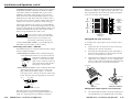
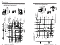
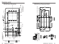
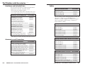
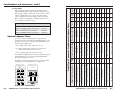
1
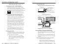
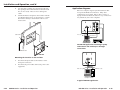
User’s Manual
RGB 400 Series
Mountable Interfaces
Extron Electronics, USA
1230 South Lewis Street, Anaheim, CA 92805
800.633.9876 714.491.1500 FAX 714.491.1517
USA
Extron Electronics, Europe
Beeldschermweg 6C, 3821 AH Amersfoort
+31.33.453.4040 FAX +31.33.453.4050
The Netherlands
Extron Electronics, Asia
135 Joo Seng Rd. #04-01, PM Industrial Bldg.
+65.383.4400 FAX +65.383.4664
Singapore 368363
Extron Electronics Information
ExtronWEB™: www.extron.com
ExtronFAX™: 714.491.0192
24-hour access—worldwide!
68-364-01
Printed in the USA
Precautions
Safety Instructions • English
This symbol is intended to alert the user of important
operating and maintenance (servicing) instructions
in the literature provided with the equipment.
This symbol is intended to alert the user of the
presence of uninsulated dangerous voltage within
the product's enclosure that may present a risk of
electric shock.
Caution
Read Instructions • Read and understand all safety and operating
instructions before using the equipment.
Retain Instructions • The safety instructions should be kept for future
reference.
Follow Warnings • Follow all warnings and instructions marked on the
equipment or in the user information.
Avoid Attachments • Do not use tools or attachments that are not
recommended by the equipment manufacturer because they may be
hazardous.
Consignes de Sécurité • Français
Ce symbole sert à avertir l’utilisateur que la
documentation fournie avec le matériel contient des
instructions importantes concernant l’exploitation
et la maintenance (réparation).
Ce symbole sert à avertir l’utilisateur de la présence
dans le boîtier de l’appareil de tensions dangereuses
non isolées posant des risques d’électrocution.
Attention
Lire les instructions• Prendre connaissance de toutes les consignes de
sécurité et d’exploitation avant d’utiliser le matériel.
Conserver les instructions• Ranger les consignes de sécurité afin de
pouvoir les consulter à l’avenir.
Respecter les avertissements • Observer tous les avertissements et
consignes marqués sur le matériel ou présentés dans la documentation
utilisateur.
Eviter les pièces de fixation • Ne pas utiliser de pièces de fixation ni
d’outils non recommandés par le fabricant du matériel car cela
risquerait de poser certains dangers.
Sicherheitsanleitungen • Deutsch
Dieses Symbol soll dem Benutzer in der im
Lieferumfang enthaltenen Dokumentation
besonders wichtige Hinweise zur Bedienung und
Wartung (Instandhaltung) geben.
Dieses Symbol soll den Benutzer darauf aufmerksam
machen, daß im Inneren des Gehäuses dieses
Produktes gefährliche Spannungen, die nicht isoliert
sind und die einen elektrischen Schock verursachen
können, herrschen.
Achtung
Lesen der Anleitungen • Bevor Sie das Gerät zum ersten Mal verwenden,
sollten Sie alle Sicherheits-und Bedienungsanleitungen genau
durchlesen und verstehen.
Aufbewahren der Anleitungen • Die Hinweise zur elektrischen Sicherheit
des Produktes sollten Sie aufbewahren, damit Sie im Bedarfsfall darauf
zurückgreifen können.
Befolgen der Warnhinweise • Befolgen Sie alle Warnhinweise und
Anleitungen auf dem Gerät oder in der Benutzerdokumentation.
Keine Zusatzgeräte • Verwenden Sie keine Werkzeuge oder Zusatzgeräte,
die nicht ausdrücklich vom Hersteller empfohlen wurden, da diese eine
Gefahrenquelle darstellen können.
Instrucciones de seguridad • Español
Este símbolo se utiliza para advertir al usuario sobre
instrucciones importantes de operación y
mantenimiento (o cambio de partes) que se desean
destacar en el contenido de la documentación
suministrada con los equipos.
Este símbolo se utiliza para advertir al usuario sobre
la presencia de elementos con voltaje peligroso sin
protección aislante, que puedan encontrarse dentro
de la caja o alojamiento del producto, y que puedan
representar riesgo de electrocución.
Precaucion
Leer las instrucciones • Leer y analizar todas las instrucciones de
operación y seguridad, antes de usar el equipo.
Conservar las instrucciones • Conservar las instrucciones de seguridad
para futura consulta.
Obedecer las advertencias • Todas las advertencias e instrucciones
marcadas en el equipo o en la documentación del usuario, deben ser
obedecidas.
Evitar el uso de accesorios • No usar herramientas o accesorios que no
sean especificamente recomendados por el fabricante, ya que podrian
implicar riesgos.
FCC Class A Notice
Warning
Power sources • This equipment should be operated only from the power source
indicated on the product. This equipment is intended to be used with a main
power system with a grounded (neutral) conductor. The third (grounding) pin is
a safety feature, do not attempt to bypass or disable it.
Power disconnection • To remove power from the equipment safely, remove all
power cords from the rear of the equipment, or the desktop power module (if
detachable), or from the power source receptacle (wall plug).
Power cord protection • Power cords should be routed so that they are not likely to
be stepped on or pinched by items placed upon or against them.
Servicing • Refer all servicing to qualified service personnel. There are no userserviceable parts inside. To prevent the risk of shock, do not attempt to service
this equipment yourself because opening or removing covers may expose you to
dangerous voltage or other hazards.
Slots and openings • If the equipment has slots or holes in the enclosure, these are
provided to prevent overheating of sensitive components inside. These openings
must never be blocked by other objects.
Lithium battery • There is a danger of explosion if battery is incorrectly replaced.
Replace it only with the same or equivalent type recommended by the
manufacturer. Dispose of used batteries according to the manufacturer's
instructions.
Avertissement
Alimentations• Ne faire fonctionner ce matériel qu’avec la source d’alimentation
indiquée sur l’appareil. Ce matériel doit être utilisé avec une alimentation
principale comportant un fil de terre (neutre). Le troisième contact (de mise à la
terre) constitue un dispositif de sécurité : n’essayez pas de la contourner ni de la
désactiver.
Déconnexion de l’alimentation• Pour mettre le matériel hors tension sans danger,
déconnectez tous les cordons d’alimentation de l’arrière de l’appareil ou du
module d’alimentation de bureau (s’il est amovible) ou encore de la prise secteur.
Protection du cordon d’alimentation • Acheminer les cordons d’alimentation de
manière à ce que personne ne risque de marcher dessus et à ce qu’ils ne soient
pas écrasés ou pincés par des objets.
Réparation-maintenance • Faire exécuter toutes les interventions de réparationmaintenance par un technicien qualifié. Aucun des éléments internes ne peut être
réparé par l’utilisateur. Afin d’éviter tout danger d’électrocution, l’utilisateur ne
doit pas essayer de procéder lui-même à ces opérations car l’ouverture ou le
retrait des couvercles risquent de l’exposer à de hautes tensions et autres dangers.
Fentes et orifices • Si le boîtier de l’appareil comporte des fentes ou des orifices,
ceux-ci servent à empêcher les composants internes sensibles de surchauffer. Ces
ouvertures ne doivent jamais être bloquées par des objets.
Lithium Batterie • Il a danger d'explosion s'll y a remplacment incorrect de la
batterie. Remplacer uniquement avec une batterie du meme type ou d'un ype
equivalent recommande par le constructeur. Mettre au reut les batteries usagees
conformement aux instructions du fabricant.
Vorsicht
Stromquellen • Dieses Gerät sollte nur über die auf dem Produkt angegebene
Stromquelle betrieben werden. Dieses Gerät wurde für eine Verwendung mit
einer Hauptstromleitung mit einem geerdeten (neutralen) Leiter konzipiert. Der
dritte Kontakt ist für einen Erdanschluß, und stellt eine Sicherheitsfunktion dar.
Diese sollte nicht umgangen oder außer Betrieb gesetzt werden.
Stromunterbrechung • Um das Gerät auf sichere Weise vom Netz zu trennen,
sollten Sie alle Netzkabel aus der Rückseite des Gerätes, aus der externen
Stomversorgung (falls dies möglich ist) oder aus der Wandsteckdose ziehen.
Schutz des Netzkabels • Netzkabel sollten stets so verlegt werden, daß sie nicht
im Weg liegen und niemand darauf treten kann oder Objekte darauf- oder
unmittelbar dagegengestellt werden können.
Wartung • Alle Wartungsmaßnahmen sollten nur von qualifiziertem
Servicepersonal durchgeführt werden. Die internen Komponenten des Gerätes
sind wartungsfrei. Zur Vermeidung eines elektrischen Schocks versuchen Sie in
keinem Fall, dieses Gerät selbst öffnen, da beim Entfernen der Abdeckungen die
Gefahr eines elektrischen Schlags und/oder andere Gefahren bestehen.
Schlitze und Öffnungen • Wenn das Gerät Schlitze oder Löcher im Gehäuse
aufweist, dienen diese zur Vermeidung einer Überhitzung der empfindlichen
Teile im Inneren. Diese Öffnungen dürfen niemals von anderen Objekten
blockiert werden.
Litium-Batterie • Explosionsgefahr, falls die Batterie nicht richtig ersetzt wird.
Ersetzen Sie verbrauchte Batterien nur durch den gleichen oder einen
vergleichbaren Batterietyp, der auch vom Hersteller empfohlen wird. Entsorgen
Sie verbrauchte Batterien bitte gemäß den Herstelleranweisungen.
Advertencia
Alimentación eléctrica • Este equipo debe conectarse únicamente a la fuente/tipo
de alimentación eléctrica indicada en el mismo. La alimentación eléctrica de este
equipo debe provenir de un sistema de distribución general con conductor
neutro a tierra. La tercera pata (puesta a tierra) es una medida de seguridad, no
puentearia ni eliminaria.
Desconexión de alimentación eléctrica • Para desconectar con seguridad la
acometida de alimentación eléctrica al equipo, desenchufar todos los cables de
alimentación en el panel trasero del equipo, o desenchufar el módulo de
alimentación (si fuera independiente), o desenchufar el cable del receptáculo de
la pared.
Protección del cables de alimentación • Los cables de alimentación eléctrica se
deben instalar en lugares donde no sean pisados ni apretados por objetos que se
puedan apoyar sobre ellos.
Reparaciones/mantenimiento • Solicitar siempre los servicios técnicos de personal
calificado. En el interior no hay partes a las que el usuario deba acceder. Para
evitar riesgo de electrocución, no intentar personalmente la reparación/
mantenimiento de este equipo, ya que al abrir o extraer las tapas puede quedar
expuesto a voltajes peligrosos u otros riesgos.
Ranuras y aberturas • Si el equipo posee ranuras o orificios en su caja/alojamiento,
es para evitar el sobrecalientamiento de componentes internos sensibles. Estas
aberturas nunca se deben obstruir con otros objetos.
Batería de litio • Existe riesgo de explosión si esta batería se coloca en la posición
incorrecta. Cambiar esta batería únicamente con el mismo tipo (o su equivalente)
recomendado por el fabricante. Desachar las baterías usadas siguiendo las
instrucciones del fabricante.
Note: This equipment has been tested and found to comply with the limits for a
Class A digital device, pursuant to part 15 of the FCC Rules. These limits are designed
to provide reasonable protection against harmful interference when the equipment is
operated in a commercial environment. This equipment generates, uses and can
radiate radio frequency energy and, if not installed and used in accordance with the
instruction manual, may cause harmful interference to radio communications.
Operation of this equipment in a residential area is likely to cause harmful
interference, in which case the user will be required to correct the interference at his
own expense.
Note: This unit was tested with shielded cables on the peripheral devices. Shielded
cables must be used with the unit to ensure compliance.
Extron’s Warranty
Extron Electronics warrants this product against defects in materials and
workmanship for a period of two years from the date of purchase. In the event of
malfunction during the warranty period attributable directly to faulty workmanship
and/or materials, Extron Electronics will, at its option, repair or replace said products
or components, to whatever extent it shall deem necessary to restore said product to
proper operating condition, provided that it is returned within the warranty period,
with proof of purchase and description of malfunction to:
USA, Canada,
South America, and
Central America:
Extron Electronics
1230 South Lewis Street
Anaheim, CA 92805, USA
Europe, Africa, and
the Middle East:
Asia:
Extron Electronics, Europe
Beeldschermweg 6C
3821 AH Amersfoort
The Netherlands
Extron Electronics, Asia
135 Joo Seng Road, #04-01
PM Industrial Bldg.
Singapore 368363
This Limited Warranty does not apply if the fault has been caused by misuse,
improper handling care, electrical or mechanical abuse, abnormal operating conditions
or non-Extron authorized modification to the product.
If it has been determined that the product is defective, please call Extron and ask for an
Applications Engineer at (714) 491-1500 (USA), 31.33.453.4040 (Europe), or 65.383.4400
(Asia) to receive an RA# (Return Authorization number). This will begin the repair
process as quickly as possible.
Units must be returned insured, with shipping charges prepaid. If not insured, you
assume the risk of loss or damage during shipment. Returned units must include the
serial number and a description of the problem, as well as the name of the person to
contact in case there are any questions.
Extron Electronics makes no further warranties either expressed or implied with
respect to the product and its quality, performance, merchantability, or fitness for any
particular use. In no event will Extron Electronics be liable for direct, indirect, or
consequential damages resulting from any defect in this product even if Extron
Electronics has been advised of such damage.
Please note that laws vary from state to state and country to country, and that some
provisions of this warranty may not apply to you.
Table of Contents
Chapter 1 • Introduction .......................................................... 1-1
About this Manual ................................................................ 1-2
About the RGB 400 Series Interfaces .......................... 1-2
Features ...................................................................................... 1-2
RGB 400 Series features ......................................................... 1-2
Additional RGB 404 features ................................................ 1-2
Additional RGB 406 and RGB 408 features .......................... 1-2
Chapter 2 • Installation and Operation ......................... 2-1
Installation Overview .......................................................... 2-2
Installation and Operation Instructions .................... 2-3
Determining installation location ........................................ 2-3
Preparing the installation site, installing the wall box ....... 2-4
Front and rear panel (circuit board) features ...................... 2-6
RGB 404 front and rear features ........................................... 2-6
RGB 406 front and rear features ........................................... 2-8
RGB 408 front and rear features ........................................ 2-12
Setting DIP switches and jumpers ....................................... 2-12
DIP switches ..................................................................... 2-12
Jumpers ........................................................................... 2-12
Attaching adapter plates (RGB 408) ................................... 2-13
Cabling and connections ..................................................... 2-14
Attaching cables to pass-through connectors .................. 2-14
Connecting shields .............................................................. 2-15
Connecting audio cables — RGB 404 ................................ 2-16
Connecting audio cables — RGB 406, RGB 408 ................ 2-18
Connecting input cables and video output cables ........... 2-18
Attaching power cables ...................................................... 2-18
Using installation cable ...................................................... 2-19
Pre-installation testing/troubleshooting ............................ 2-19
Mounting the interface to the wall box ............................ 2-21
Application diagrams .......................................................... 2-23
Appendix A • Specifications ................................................. A-1
Appendix B • Templates ............................................................ B-1
RGB 406 Cut-out Template ................................................ B-2
RGB 404 Cut-out Template ................................................ B-3
RGB 408 Cut-out Template ................................................ B-4
RGB 400 Series • Table of Contents
i
Table of Contents, cont’d
Appendix C • Dimensions ........................................................ C-1
RGB
RGB
RGB
RGB
404
406
408
408
Panel
Panel
Panel
Panel
Dimensions ............................................... C-2
Dimensions ............................................... C-5
Dimensions ............................................... C-6
Dimension Details ................................. C-7
Appendix D • Accessories and Part Numbers .......... D-1
Interfaces and Included Parts ........................................ D-2
Accessories and Connectors ........................................... D-2
Cables ......................................................................................... D-3
Optional Adapter Plates ................................................... D-4
RGB 400 Series
1
Chapter One
Introduction
About this Manual
About The RGB 400 Series Interfaces
Features
68-364-01 D
Printed in the USA
07 00
ii
RGB 400 Series • Table of Contents
Introduction, cont’d
Introduction
About this Manual
This manual contains information about the RGB 400 Series
interfaces and on how to operate and configure them.
RGB 400 Series
About The RGB 400 Series Interfaces
The RGB 400 Series are 300 MHz (-3dB) bandwidth, analog
computer-video interfaces that can be mounted in walls or
furniture. The RGB 406 is two-gang wall plate size, the
RGB 404 is three-gang size, and the RGB 408 is four-gang
size. All are available with black, white, or gray panels.
Features
RGB 400 Series features
Horizontal centering control — Shifts the image horizontally.
Level control — Adjusts the image brightness.
Peaking control — Adjusts the image sharpness.
Sync output options — Six BNC connectors allow separate
horizontal, vertical and composite sync outputs.
Sync-on-green (SOG) is output only if SOG is input.
Digital Display Sync Processing™ (DDSP™) — Sync is
output in its original state to ensure compatibility
with digital display products.
75 ohm video termination switch — For applications
where a local computer monitor is not being used.
Additional RGB 404 features
The RGB 404 offers the following features in addition to the
RGB 400 Series features listed above:
Composite video pass-through RCA connector
2
Chapter Two
Installation and Operation
Installation Overview
S-video pass-through 4-pin mini DIN connector
Network pass-through (RJ-45 connector)
Two 2-channel audio outputs (unbalanced in, balanced
out) on RCA and PC stereo connectors
Additional RGB 406 and RGB 408 features
The RGB 406 and RGB 408 offer these features in addition
to the RGB 400 Series features listed above:
Two channels of audio (unbalanced in, balanced out)
Optional pass-through adapter plates (RGB 408 only)
1-2
RGB 400 Series • Introduction
Installation and Operation Instructions
Installation and
Operation,
cont’d
Installation
and
Operation
Installation Overview
To install and set up an RGB 400 Series interface, follow
these basic steps:
2-2
1
Determine the installation location.
2
Prepare the site for installation. Use the supplied
template to mark the rough-in cutout, then cut out
the wallboard or wood.
3
Set the DIP (dual in-line package) switches and
jumpers. These items will be inaccessible after
installation.
4
For the RGB 408, attach optional adapter plates, and
attach output cables to the back sides of the adapter
plates.
5
For all models, connect the wires and cables for
power, audio output and pass-through signals.
These items will be inaccessible after installation.
6
For all models, set the front panel High Z/75 Ohm
video termination toggle switch.
7
Temporarily connect the input cables. Connect any
cables whose signals will be routed through the
optional adaptor pass-through plates.
8
Connect power cables to the input and output
devices. Turn on the input and output devices.
9
The image should now display on screen. If it does
not display, or if the picture displays incorrectly,
double check and make adjustments to cables, DIP
switches and jumpers as needed. Refer to the
“Pre-installation testing/troubleshooting” section in
this chapter.
10
Temporarily disconnect the input cables from the
front panel of the interface, and disconnect the power
from the interface.
11
Mount the interface in the wall or furniture.
12
Reconnect the computer video and audio input
cables to the interface, apply power, and readjust
horizontal centering as needed via the front panel
control.
RGB 400 Series • Installation and Operation
Installation and Operation Instructions
Determining installation location
Take cabling and power availability and the location of wall
studs into consideration when selecting an installation site.
You may need to install the cables in the wall, furniture or
conduits before installing the interface. Choose a location
that will allow cable runs without interference, preferably
next to a 2” x 4” wall stud.
The RGB 400 Series interfaces each consist of a front panel
with an attached circuit board. They are typically installed
in standard 2-, 3- or 4-gang, 2.5-inch deep electrical wall
boxes. A metal wall box (provided by Extron) is preferred,
but a plastic box (or no wall box at all) can be used as long
as it conforms to local code restrictions and the interface’s
size requirements. If a wall box is used, it must be attached
to wall studs within the wall.
The drawing below illustrates the typical depth required to
accommodate the maximum bend of high resolution (SHR)
coaxial and miniature coaxial cables inside a wall box.
Approximately 3.3"
Approximately 2.5"
Mini-Coax
Cable
SHR Coax
Cable
Circuit Board
Front Panel
Minimum installation depth needed for
maximum coaxial cable bend
Cut-out (rough-in) templates and dimensional drawings are
provided in the appendices of this manual.
RGB 400 Series • Installation and Operation
2-3
Installation and Operation, cont’d
Preparing the installation site and
installing the wall box
Actual-size rough-in templates for each model are provided
in Appendix B. If needed, make a 100% size photocopy of
the appropriate template to use for installation. Compare
the photocopy with the faceplate and wall box to make sure
the photocopy size is the same as the equipment.
Wall Stud
Wall Box
Use the template as a guide to mark and cut the hole in the
wall or furniture through which the interface will be installed.
The innermost line represents the opening where material
will be removed and the wall box will be installed.
1.
Cut out the center portion (up to the guidelines) of the
cut-out (rough-in) template.
2.
Place the template on the surface where the interface
will be installed. Use a soft pencil to mark the
guidelines for the opening on the wall/furniture.
3.
Cut out the material from the cut-out area with a
jigsaw or small hand saw.
4.
Check the opening size by inserting the wall box (if
used) or the interface (if no wall box is used) into the
opening. The wall box will be mounted flush with the
outer wall or furniture surface. The box and/or
interface should fit easily into the opening.
5.
If needed, use a saw, file or sandpaper to enlarge the
hole. Smooth the edges of the opening to avoid
damage or injury to yourself or the cables during
installation.
6.
2-4
Screws or Nails
Attaching the wall box to wall studs
To attach the wall box to wood, use four #8 to # 10
wood or sheet metal screws. A minimum of 1/2 inch
(1.25 cm) of screw threads must penetrate the wood.
If the wood is a 2 x 4, such as a wall stud, 10-penny or
larger nails can be used.
To attach the electrical wall box to metal, use four #8
or #10 sheet metal screws (self-tapping) or #8 or #10
machine bolts with matching nuts.
7.
Output cables will usually be out of sight inside a
wall, for example. Feed the cables through the wall
box “punch-out” holes for connection to the interface.
Cable clamps should be used to hold the cables in
place for strain relief.
8.
Exposed cable shields (braids or foil) are potential
sources of short circuits. Trim back and/or insulate
shields with heat shrink. Details for typical maximum
coaxial cable bend inside a wall box are given on
page 2-3.
9.
Configure, cable and test the interface before securing
the interface to the wall box. Configuration consists of
setting circuit board DIP switches and jumpers based
on installation requirements. See page 2-14 for more
information.
Attach the wall box to the wall stud (2” x 4”) with
nails or screws, leaving the front edge flush with the
wall surface, as shown in the following illustration.
RGB 400 Series • Installation and Operation
Flush with
Wall Surface
RGB 400 Series • Installation and Operation
2-5
Installation and Operation, cont’d
Front and rear panel (circuit board) features
18
17
Yellow
18
17
16
19
Red
Black
Green
J11
RGB 404 front and rear features
J12
J9
3
4
5
CH1R
6
8
9
10
CH1R
1 2
1 = +5V 20 mA max.
2 = –5V 20 mA max.
3 = Ground
PC
H. SHIFT
RGB 404
8
7
6
5
9
.8V .9V
3 2 1
J13
1. ON = Remove
serration pulses.
2. ON = Digital
display sync.
SW1
NETWORK
Extron
J8
J10
J13
ON
AUTO POWER
A
U
D
I
O
7
75 Ohm
SW1
ON
2
R
CH1L
L
1
S-VIDEO
33-323-01
L
3.5 mm
Signal
RCA
REV. A 79-08
R
Ground
Ground
CH1L & CH1R outputs are CH2L & CH2R outputs are
generated from RCA inputs.
generated from 3.5 mm inputs.
VIDEO
HIGH Z
INPUT
10
H
J9
RGB 406/
RGB 408
Captive
Screw
Connector
B
.7V
.7V
J10
11 12
13
.8V
.7V
V
J8
14
G
J9
R
CS
.9V
J10
J8
33-398-01 B 08 99
15
REAR
2
1
3
4
5
6
7
FRONT
1
Auto power LED — If active sync pulses are present, power
and this LED turn on. If not, power and this LED turn off.
2
H. Shift (horizontal shift) control — This controls the
horizontal centering. If output is SOG or if DIP SW1-2
(DDSP) is set to On, the horizontal shift control is disabled.
3
Input — This 9-pin D-sub male connector is for RGB input.
4
High Z/75 Ohm switch — For proper video termination, set
this switch to 75 Ohms if no local monitor will be
connected.
5
PC type 3.5 mm stereo audio input connector — This
connector is for unbalanced
Tip (+)
Sleeve (GND)
input to audio channel 2. Wire
the input plug as shown here.
Ring (R, -)
8
Pin assignment label for the audio output captive screw
connector (item 9) — Audio output wiring is discussed in
the cabling section of this chapter.
9
Audio output captive screw connector — Use this
connector for the balanced output from both audio channels
(1 and 2). See the wiring diagram label (item 8) and the
cabling section in this manual for wiring instructions.
10
J13 jumper — Pin 1 = +5V, pin 2 = -5V, pin 3 = ground.
11
SW1 DIP switches — 1. On = Removes serration pulses.
2. On = Enables Digital Display Sync Processing (DDSP).
12
J10 blue gain/peaking jumper — Settings are shown on
the label located below the circuit board.
13
J9 green gain/peaking jumper
14
J8 red gain/peaking jumper
15
Circuit board — Only key components are shown here.
16
Twisted-pair wires — Splice these wires to a 12 to 24VAC or
VDC power source.
17
Composite video pass-through RCA connector—If unused,
this connector can be replaced with a 0.31” diam. plug.
18
S-video pass-through 4-pin mini DIN connector — This
connector can be replaced with a 0.50” diam. plug.
19
BNC output connectors — These 6 connectors are for video
and sync output. Connect the coax cables’ BNC connectors
as shown here for red, green and blue
H
G
video output, and either separate
B
R
V
horizontal and vertical sync or
CS
composite sync.
Tip (L, +)
Sleeve (GND)
6
Left and right audio channel RCA connectors — These
connectors are for unbalanced input to audio channel 1.
Wire the input plugs as shown below.
Tip
7
2-6
Sleeve ( )
Network pass-through RJ-45 connector
RGB 400 Series • Installation and Operation
RGB 400 Series • Installation and Operation
2-7
Installation and Operation, cont’d
RGB 406 front and rear features
14
9
SW1 DIP switches —
1. On = Removes serration pulses.
2. On = Enables Digital Display Sync Processing
(DDSP).
J11
J12
J9
10
J10 blue gain/peaking jumper — Settings are shown on
the label located below the circuit board.
11
J9 green gain/peaking jumper
12
J8 red gain/peaking jumper
13
Circuit board — Only key components are shown here.
14
Twisted-pair wires — Splice these wires to a
12 to 24VAC or VDC power source.
HIGH Z
INPUT
1 2
SW1
J8
J10
ON
75 Ohm
AUTO POWER
AUDIO
J13
H. SHIFT
1 = +5V 20 mA max.
2 = –5V 20 mA max.
3 = Ground
1
RGB 406
2
3
5
4
ON
Extron
SW1
7
RGB 406/
RGB 408
Captive
Screw
Connector
8
B
.7V
.7V
J10
9 10
FRONT
2-8
H
J9
J13
1. ON = Remove
serration pulses.
2. ON = Digital
display sync.
6
.8V .9V
3 2 1
11
.8V
.7V
V
.9V
J8
12
G
J9
R
CS
J10
J8
33-398-01 B 08 99
13
REAR
1
Auto power LED — If this LED is on, power and sync
pulses are present. If no sync is present, power and
this LED turn off.
2
H. Shift (horizontal shift) control — This controls
horizontal centering. If output is SOG or if DIP SW1-2
(DDSP) is set to On, the horizontal shift control is
disabled.
3
Input — This 9-pin D-sub male connector is for RGB
analog input.
4
Audio 3.5 mm stereo PC-type connector for unbalanced
input — See page 2-12 for an input plug wiring diagram.
5
High Z/75 Ohm switch — For proper video termination,
set this switch to 75 Ohms if no local monitor will be
connected.
6
BNC output connectors — These 6 connectors are for
video and sync output. Connect the coaxial cables’ BNC
connectors as shown here for red,
H
G
green and blue video output, and
B
R
V
either separate horizontal and
CS
vertical sync or composite sync.
7
J13 jumper — Pin 1 = +5V, pin 2 = -5V, pin 3 = ground.
8
Audio output 3.5 mm, 5-pole captive screw connector —
The label below this connector provides a wiring
diagram for balanced audio output.
RGB 400 Series • Installation and Operation
RGB 400 Series • Installation and Operation
2-9
Installation and Operation, cont’d
RGB 408 front and rear features
15
J11
J12
J9
HIGH Z
INPUT
1 2
SW1
J8
J10
ON
75 Ohm
AUTO POWER
AUDIO
J13
H. SHIFT
1 = +5V 20 mA max.
2 = –5V 20 mA max.
3 = Ground
Extron
2
3
4
5
6
1
Auto power LED — If this LED is on, power and video
sync pulses are present. If no sync is present, power
and this LED turn off.
2
H. Shift (horizontal shift) control — This controls
horizontal centering. If output is SOG or if DIP SW1-2
(DDSP) is set to On, the horizontal shift control is disabled.
3
Input — This 9-pin D-sub male connector is for RGB
analog input.
4
Audio input 3.5 mm stereo PC-type connector for
unbalanced input — Wire the PC audio input plug as
shown here.
Tip (+)
ON
RGB 408
FRONT
1
SW1
.8V .9V
3 2 1
J13
1. ON = Remove
serration pulses.
2. ON = Digital
display sync.
H
J9
RGB 406/
RGB 408
Captive
Screw
Connector
B
.7V
.7V
J10
.8V
.7V
.9V
J8
V
G
J9
R
CS
J10
J8
33-398-01 B 08 99
REAR
6
7
8
9 10 11
12
13
14
7
BNC output connectors — These 6 connectors are for
video and sync output. Connect the coaxial cables’
BNC connectors as shown here for red, green and blue
video output, and either separate
H
G
B
R
horizontal and vertical sync or
V
CS
composite sync.
8
J13 jumper — Pin 1 = +5V, pin 2 = -5V, pin 3 = ground.
9
Audio output 3.5 mm, 5-pole captive screw connector
— The label below this connector provides a wiring
diagram for balanced audio output.
10
SW1 DIP switches —
1. On = Remove serration pulses.
2. On = Enable Digital Display Sync Processing
(DDSP).
11
J10 blue gain/peaking jumper — Settings are shown on
the label located below the circuit board.
12
J9 green gain/peaking jumper
13
J8 red gain/peaking jumper
14
Circuit board — Only key components are shown here.
15
Twisted-pair wire — Splice these wires to a
12 to 24VAC or VDC power source.
Sleeve (GND)
Ring (R, -)
Tip (L, +)
Sleeve (GND)
5
6
2-10
High Z/75 Ohm switch — For proper video
termination, set this switch to 75 Ohms if no local
monitor will be connected.
Architectural adapter plates installation bay — Up to
four adapter plates for pass-through audio/video
connections can be attached at one time to the interface.
See the “Attaching adapter plates” section in this
chapter for installation instructions.
RGB 400 Series • Installation and Operation
RGB 400 Series • Installation and Operation
2-11
Installation and Operation, cont’d
Setting DIP switches and jumpers
DIP switches and jumpers must be set and tested before the
interface is secured into the wall box, wall or furniture.
DIP switches
ON
1 2
DIP switch module SW1 contains two DIP switches (SW1-1
and SW1-2). The module is located on the circuit board on
the back of the interface, as shown on pages 2-6,
SW1
2-7, 2-9, 2-11 and 2-13. In these illustrations, the
On position is to the left.
Different video projectors may have slightly different sync
requirements. Use the DIP switches on the interface to
make the interface’s output compatible with the projector.
DIP switch 1 (SW1-1) controls serration pulse output.
ON = No serration pulses will be output in the
composite sync signal.
OFF = Serration pulses will be output.
DIP switch 2 (SW1-2) controls sync processing.
ON = Digital Display Sync Processing (DDSP) will be
used. This may be required in order to obtain a
stable picture on some digital display devices.
When DDSP is on, horizontal shift (centering) is
disabled.
OFF = DDSP will not be used.
Jumpers
Video signals passing through long cable runs (over 125
feet) or through poor quality cables can decrease in
strength, creating signal loss. The longer the cable, the
higher the video level and the greater the peaking that will
be needed to compensate for the loss.
The gain/peaking adjustment jumpers are located on the
circuit board on the back of the interface, as shown in the
rear features sections of this manual. To configure the
jumpers, use pliers to pull the jumper shunt off the pins,
then place the jumper on the appropriate pins.
Each red (J8), green (J9) and blue (J10) jumper can be set to
one of three positions to provide unity gain (0.7 volts p-p),
0.8 volts p-p, or 0.9 volts p-p output. Select the setting that
yields the best image display. Use the diagram on the
product label (shown below) as a guide to setting the
output gain/peaking for each color.
2-12
RGB 400 Series • Installation and Operation
.7V
.8V
.7V
.9V
J10
.8V
.7V
.9V
J8
RGB 400 Series gain/peaking jumpers
0.7V — Use this for short cable runs (under 125 feet).
0.8V — Use this for long cable runs for all frequencies.
0.9V — Use this setting for long cable runs and high
frequency video signals.
Attaching adapter plates (RGB 408)
The RGB 408 can have up to 4 optional adapter plates. The
adapter plates allow for a variety of types of pass-through
audio and/or video connectors to be added to the
interface’s front panel faceplate.
Blank plates (two single-height and one double-height
plate) are included with the RGB 408 to cover unused
spaces. Other adapter plates must be ordered separately.
They also must be attached to the faceplate and cabled
before the interface is installed in the wall or furniture. The
screws needed for installing the adapter plates are built into
the plates, so no additional screws will be needed.
1.
Remove the blank plates from the interface by
unscrewing the nuts that fasten the plates to the
faceplate.
2.
Insert the adapter plate screws through the holes in
the faceplate. Attach the adapter plates to the
faceplate with the provided captive washers and
#4-40 nuts. See the illustration “Installing optional
adapter plates” on the next page.
3.
Attach the output cables to the connectors on the back
side of the adapter plates. Several adapter plates
require conductors to be soldered to the connectors.
Attach foil and braided shields to ground connections.
Make sure the interface is disconnected from
the power source before configuring jumpers.
Changing jumper settings
.9V
J9
.8V
RGB 400 Series • Installation and Operation
2-13
Installation and Operation, cont’d
Cabling RCA connectors
Adapter Plate
INP
UT
AU
TO
HIG
HZ
PO
WER
75
H.
SH
IFT
For composite video, solder the center conductor of a
coaxial cable to the central solder cup of the RCA connector.
Solder the cable’s shield to the grounded grounding tab.
See the leftmost and center illustrations below.
AU
Oh
m
DIO
#4-40 Nut w/Captive
Washer
Center
Conductor
Shield
RGB 408 (Up to 4 Plates)
RG
B4
08
Coaxial Cable
Installing optional adapter plates
Cabling and connections
Attaching cables to pass-through connectors
The RGB 404 provides pass-through connectors for
composite video, S-video, RJ-45 network These connectors
are mounted on the faceplate. The RJ-45 cable can be
plugged in from the back. Coaxial cables and/or twisted
pair wires must be soldered to the back side of the S-video
and RCA connectors, as described in this section.
Optional adapter plates with various types and
combinations of pass-through audio and video connectors
are available for the RGB 408. Many adapter plates also
require cables and wires to be soldered to the rear
connectors.
S-video connector wiring diagram
Twisted Pair
For audio, solder the signal wire of a shielded twisted-pair
cable to the central solder cup of the RCA connector. Solder
the ground wire to the grounded tab, as shown above at right.
Connecting shields
Multiconductor cables such as Extron’s Install Plenum bulk
cable contain several braided and foil shields. At the
interface end of the cable, the outer braided and foil
shields should be connected to the grounded metal wall
box (or to a grounding wire if a metal wall box is not used).
The wires that make up the braided shield can be
unbraided, then twisted together to form a large, multistrand wire that can be folded back under the wall box
cable clamp or attached to the metal wall box with a screw.
See the illustration below.
To prevent short circuits, the outer foil shield
can be cut back to the point where the cable
exits the cable clamp. Both the braided and foil
shields should be connected to an equipment
ground at the other end of the cable.
Red
Green
Yellow
The illustration below identifies the S-video connector
signal leads. For the RGB 404, splice and solder the four
wires from this connector
Luminance
Chrominance
to user-supplied coaxial
signal
signal
cables. Insulate the
soldered connections to
Shield tab
prevent shorts. You can
also use the connector’s
shield tabs for
chrominance and
Luminance
Chrominance
luminance ground tie
ground
ground
points.
RCA Connector
Attaching coaxial and twisted-pair cables to
RCA connectors
Cabling S-video connectors
Black
Central Solder
Cup
Grounding Tab
Metal Wall Box
Screw
Cable Clamp
Braided Shield
Install Cable
Foil Shield
Grounding outer braided and foil shields
2-14
RGB 400 Series • Installation and Operation
RGB 400 Series • Installation and Operation
2-15
Installation and Operation, cont’d
If shielded twisted-pair wires are used for audio output for
the RGB 404, RGB 406 or RGB 408, the shields should be
connected to either pin 3 (RGB 406/408) or pins 3 and 8
(RGB 404) of the audio output captive screw connector.
Twist the wires from the braided shield together to form a
multi-strand wire, then insert it into the receptacle side of
the captive screw connector. See the “Wiring audio output
captive screw connectors” illustration on the next page.
Twisted-pair shields are not used for most other RGB 400
Series applications, even when twisted-pair wires are used.
For those other applications, twist the shields together, and
fold them back under the wall box cable clamp or attach
them to the grounded wall box with a screw.
To prevent short circuits, unused shielded
twisted-pair wires and exposed cable shields
(braided or foil) must be insulated with
electrical tape or heat shrink, and secured.
Connect coaxial cables’ shields to a ground through the
individual connectors (BNC, S-video or RCA).
Connecting audio cables — RGB 404
The RGB 404 creates two 2-channel, balanced audio outputs
from two unbalanced inputs.
• Audio channel one (CH1) consists of unbalanced input
on two RCA input connectors (one each for left and
right input), and balanced output
on pins 1 – 5 of the 10-pole audio
captive screw connector on the rear
Tip Sleeve ( )
of the circuit board. Wire the RCA
input plugs as shown at left.
signal. For example, the input signals from the left side of
channel one (CH1L) are output as CH1L+ and CH1L-. The
following illustration shows the audio inputs and outputs
and how to wire the audio connectors.
L
Channel 1
L
GND
GND
R
R
L
Channel 2
L
GND
GND
R
R
Female
Male
Captive Screw
Connector
Base
Channel 1
from Audio L, R
RCA
Connectors
Channel 2
from PC
3.5mm
Connector
Circuit Board
Wiring RGB 404 audio connectors
To wire the audio output captive screw connector, follow
these steps:
1.
Prepare the wires for insertion into the connector by
trimming off 3/16 inch of insulation.
2.
Following the wiring diagram found on the label on
the back of the faceplate or in this manual, insert the
wires one at a time into the connector.
3.
Tighten the wire clamp in the connector by turning the
appropriate screw clockwise. Do not overtighten the
screw. Avoid touching circuit board components with
the ends of the wires. See the illustration below.
Ground/Shield
• Audio channel two (CH2) consists of unbalanced left and
right input from the single PC-type 3.5 mm audio
plug, and balanced output on pins 6 – 10 of the 10pole captive screw connector on the rear of the circuit
board. Wire the stereo PC input plug as shown here:
Ground/Shield
Tip (+)
Sleeve (GND)
Base
Ring (R, -)
Circuit Board
Tip (L, +)
RGB 404
Sleeve (GND)
Circuit Board
RGB 406 and RGB 408
Wiring audio output captive screw connectors
The audio signals are converted from unbalanced to
balanced signals as they pass through the RGB 404. As a
result, two output signals are produced for each input
2-16
RGB 400 Series • Installation and Operation
4.
The cable shields should be connected to either pins 3
and 8 (RGB 404) or pin 3 (RGB 406/408) of the audio
RGB 400 Series • Installation and Operation
2-17
Installation and Operation, cont’d
output captive screw connector. See “Connecting
shields” earlier in this chapter for details.
Connecting audio cables — RGB 406, RGB 408
Using installation cable
Extron’s Install Plenum bulk cable (shown here) is ideal for
mountable interfaces such as the RGB 400 Series models.
Six Mini, High-resolution
Coaxial Conductors
Each RGB 406 or RGB 408 accepts an unbalanced audio
input from a front panel 3.5 mm PC-type stereo connector,
and it outputs two channels of balanced audio on a 3.5 mm,
5-pole captive screw connector on the rear of the circuit
board. Follow the steps listed for the RGB 404
12345
for inserting wires into captive screw
connectors. Use the label on the rear of the
faceplate (excerpted here) as a wiring guide.
Center Conductor
(Stranded)
Polyethylene Foam
Sheath
Three 20-gauge Wires
Plenum Jacket, Double Shielded
Foil and Copper Strand
Connecting input cables and video output cables
With appropriate cables, connect the computer and audio
device(s) to the interface via the front panel input
connectors. Connect all the devices for pass-through input
(network, composite video, S-video and/or other inputs)
via front panel or front adapter plate connectors.
Determine what computer-video format the display device
requires: separate horizontal and vertical sync (RGBHV),
composite sync (RGBS), or sync on green (RGsB or SOG).
No matter what format the computer outputs to the
interface, the output from the interface to the display device
can be RGBHV or RGBS. If the video format input to the
interface is RGsB (SOG), RGsB can be output to the display
device; otherwise only RGBHV and RGBS are available as
output options.
Connect the display device to the interface using coaxial
cables. Attach the cable’s BNC connectors to the
appropriate rear panel BNC connectors on the interface
based on the video format required by the display device.
Attaching power cables
Each RGB 400 Series interface requires an external voltage
source of 12 to 24 volts AC or DC (250 mA maximum, 5 W).
The interfaces are supplied with a power cord of twistedpair wire soldered to the circuit board.
1.
2.
2-18
Splice these wires to the cord of a user-supplied
power source. Polarity is not important, even if the
power source supplies DC voltage. Extron offers an
optional external power supply. See Appendix D for
the part number.
Solder and insulate the connections.
RGB 400 Series • Installation and Operation
Double Shielded
Foil and Copper Strand
Four Sets of Twisted Pair
(Stranded), Wire Braid Shield
17-Conductor Install Plenum Cable
Below is an example of how the cable can be used.
White Mini-Coax
Black Mini-Coax
Shield to Green
Blue Mini-Coax
Yellow Mini-Coax
Green Mini-Coax
Shield to Black
Red Mini-Coax
Yellow
Red
Red & Black
Twisted Pair
20 Gauge Violet
Green
20 Gauge Gray
Black
White & Black
Twisted Pair
RGB 404 Rear
Using installation cable with an RGB 404
Pre-installation testing/troubleshooting
Before installing the interface into the wall or furniture, test
the system to make sure that the connections and interface
settings are correct.
Turn on the input device(s) (computer, audio device) and
output device(s) (projector and/or monitor, speakers). The
image should now appear on the screen, and sound should
be audible.
If the image does not appear or there is no sound
1.
Ensure that all devices are plugged in.
2.
Make sure that each device is receiving power. The
interface’s Auto power indicator LED will light if the
interface is receiving power and an active sync signal.
RGB 400 Series • Installation and Operation
2-19
Installation and Operation, cont’d
3.
Check the cabling and the audio connector wiring,
and make adjustments as needed.
4.
Verify that the High Z/75 Ohm video input
termination toggle switch on the front panel has been
set correctly.
5.
For digital display devices (including LCD, DLP and
plasma devices), try turning DDSP on or off using the
rear panel SW1-2 DIP switch.
6.
Call Extron’s customer support hotline if needed.
If the image does not display correctly
1.
If the output image looks too green, the computer may
be sending video with sync on green (SOG), and the
display device may not be configured to handle SOG
signals. The RGB 400 Series interfaces do not strip
sync from the video input signals.
2.
If the picture bends or flags at the top of the screen, set
the serration pulse DIP switch (SW1-1) to Off.
3.
For a display device that experiences intermittent
glitches, try turning DDSP on or off using the rear
panel SW1-2 DIP switch.
4.
If the picture “hangs off” the edges of the screen,
adjust the H. Shift horizontal centering control.
5.
If the edges of the image seem to exceed their
boundaries or if thin lines and sharp edges look thick
and fuzzy, try changing the gain/peaking jumper (J10,
J9, J8) settings. If the image is too bright, decrease the
gain/peaking level.
6.
If the image appears and is stable, but it has ghosting
or blooming, check the High Z/75 Ohm video input
termination. If changing the termination doesn’t solve
the problem, try using a different input cable.
7.
If the image still does not display correctly, call
Extron’s customer support hotline.
the situation, either the pass-through connector or any
cable that was part of the installation but not used for
this test may be the source of the problem. If this test
does not produce an image or sound, the problem
may lie with an input device or an output device.
Mounting the interface to the wall box
Once the system has been cabled and tested, the interface
can be installed in the wall or furniture.
1.
Remove power from the interface and input and
output devices by disconnecting the power cords from
the power supply.
2.
Detach the input cables from the front panel.
3.
For the RGB 408 only, install the EMI strips.
To maintain proper grounding connections between
the interface faceplate and the wall box, adequate
contact between the faceplate and wall box must be
ensured. Installing the supplied EMI (electromagnetic
interference) strips will ensure the proper contact and
maintain the ground. To install the strips, do the
following:
a.
Peel off the protective, papery coating from the
back of an EMI strip.
b.
Apply the EMI strip to the center of the upper lip
of the 4-gang wall box, pressing firmly to ensure
contact. See the illustration below.
c.
Repeat steps 1 and 2 to install the other EMI conductive strip onto the lower lip of the wall box.
EMI Strips
Remove Adhesive
Backing
If no image or sound results from pass-through
connections
1.
2-20
Make sure each input device is connected to the
correct pass-through connector, which in turn is
connected to the appropriate output device.
2.
Ensure that each connector is properly wired and
grounded, and that each device is powered on.
3.
If there still is no image or sound, try cabling the input
device directly to the output device. If that resolves
RGB 400 Series • Installation and Operation
4-gang Wall Box
EMI Strip
HZ
HIG
T
INPU
75
m
Oh
8
B 40
RG
DIO
AU
RGB 408
Installing EMI strips on the wall box
RGB 400 Series • Installation and Operation
2-21
Installation and Operation, cont’d
4.
5.
For all models, carefully place the interface through
the opening in the wall or furniture and into the wall
box (if one is used). Take care not to damage the
cables.
Mount the interface faceplate to the wall box with the
provided machine screws (as shown below), or attach
the interface directly to the furniture with wood or
metal screws.
Application diagrams
Below are examples of typical system installations that
incorporate RGB 400 series interfaces. Many other
configurations are possible. Extron offers a variety of
laptop and monitor breakout cables for easy connection of
PCs, Macintosh, Sun or SGI computers.
VIDEO
S-VIDEO
L
R
HIGH Z
INPUT
75 Ohm
AUTO POWER
A
U
D
I
O
PC
NETWORK
H. SHIFT
Extron
RGB 404
LBC Cable
Cable Clamp
RJ45 Network
Cable
Laptop Computer
S-V
VID
ID
EO
EO
R
HIG
T
PU
IN
75
H
Z
Oh
m
L
A
U
D
I
O
PC
NE
OR
TW
K
Video Cassette Player
An RGB 404 application featuring a laptop
and network and S-video pass-through
connections
Install Cable
RGB 404
Mounting the interface to the wall box
INPUT
HIGH Z
75 Ohm
6.
7.
Reconnect the input cables to the interface via the
front panel connectors.
AUTO POWER
AUDIO
H. SHIFT
Extron
Reconnect the power cables and restore power to the
equipment.
RGB 406
MBC Cable
Audio Cable
SVGA Compatible
Computer w/ Audio
A typical RGB 406 application
2-22
RGB 400 Series • Installation and Operation
RGB 400 Series • Installation and Operation
2-23
Installation and Operation, cont’d
RGB 400 Series
A
Appendix A
Specifications
Specifications
2-24
RGB 400 Series • Installation and Operation
Specifications, cont’d
Specifications
These specifications apply to all models unless otherwise noted.
Video input
Number/type ............................... 1 analog RGBHV, RGBS, RGsB
Connectors .................................... 1 9-pin male D connector for
MBC/LBC cable or buffer
Nominal level(s) .......................... Analog ....... 0.3V to 1.45V p-p
Impedance .................................... 75 ohms or Hi Z, switchable (set to
75 ohms if no local monitor is connected)
Horizontal frequency .................. 15 kHz to 150 kHz
(optimum 15 kHz to 62 kHz)
Vertical frequency ....................... 30 Hz to 170 Hz
Return loss .................................... -30dB @ 5 MHz
Video throughput
Gain ............................................... Unity (0.7V), 15% with 3dB peaking (0.8V),
30% with 6dB peaking (0.9V)
Bandwidth .................................... 300 MHz (-3dB)
Video output
Number/type/format ................ 1 analog RGBHV, RGBS, RGsB
Connectors .................................... 6 BNC female
Nominal level ............................... Analog ....... 0.7V p-p, 0.8V p-p, or
0.9V p-p (internal jumperselectable) w/peaking
Impedance .................................... 75 ohms
Return loss .................................... -30dB @ 5 MHz
Sync
Input type ..................................... Autodetect RGBHV, RGBS, RGsB (accepts
RGsB but does not strip from video)
Output type .................................. RGBHV ...... at all times
RGBS .......... at all times
RGsB .......... only when input is RGsB
Input level ..................................... 2.0V to 5.5V p-p with +0.2VDC offset max.
Output level .................................. 4.0V to 5.0V p-p
Input impedance .......................... 10 kohms
Output impedance ....................... 75 ohms
Max propagation delay ............... 50 nS
Max rise/fall time ........................ 2.5 nS
Polarity .......................................... Positive or negative
A-2
RGB 400 Series • Specifications
Audio input — RGB 404
Number/type ............................... 2 stereo, unbalanced; 1.0Vrms (+4dBu),
20 Hz to 20 kHz
Connectors .................................... Ch. 1 ........... 2 RCA female jacks
Ch. 2 ........... 3.5 mm stereo female jack
(2 channel), unbalanced;
tip (L), ring (R), sleeve (gnd)
Impedance .................................... 10 kohms, DC coupled
Minimum level ............................. 100mV
Maximum level ............................ +8.5dBu
Audio input — RGB 406 and RGB 408
Number/type ............................... 1 stereo, unbalanced; 1.0Vrms (+4dBu),
20 Hz to 20 kHz
Connectors .................................... 3.5 mm stereo female jack (2 channel),
unbalanced; tip (L), ring (R), sleeve (gnd)
Impedance .................................... 10 kohms, DC coupled
Minimum level ............................. 100mV
Maximum level ............................ +8.5dBu
Audio throughput — RGB 404 (channels 1 and 2),
RGB 406 and RGB 408
Gain ............................................... Unbalanced 0dB, balanced +6dB
Response ....................................... ±0.5dB @ 20 Hz to 20 kHz
THD + Noise ................................ 0.03% @1 kHz, 0.3% @ 20 kHz
at rated maximum output drive
S/N ................................................ >90dB, output 14dBu, balanced
Stereo channel separation ........... >95dB @ 1 kHz to 20 kHz
Audio output — RGB 404 (channels 1 and 2)
Number/type ............................... 2 buffered, stereo (2 channel),
balanced/unbalanced
Connectors .................................... 3.5 mm captive screw terminal,
5 conductor
Impedance .................................... 50 ohms unbalanced, 100 ohms balanced
Gain error ...................................... ±0.1dB channel to channel
Drive (600 ohm) ........................... +14dBu, balanced at stated %THD+N
Audio output — RGB 406 and RGB 408
Number/type ............................... 1 buffered, stereo (2 channel),
balanced/unbalanced
Connectors .................................... 3.5 mm captive screw terminal, 5 conductor
RGB 400 Series • Specifications
A-3
Specifications, cont’d
Impedance .................................... 50 ohms, unbalanced, 100 ohms balanced
Gain error ...................................... ±0.1dB channel to channel
Drive (600 ohm) ........................... +14dBu, balanced at stated %THD+N
General
Approvals ..................................... UL, CE, FCC Class A
MTBF ............................................. 30,000 hours
Warranty ....................................... 2 years parts and labor
Specifications are subject to change without notice.
Power ............................................. 12 to 24VAC or VDC, 0.25 A, 5 watts,
external (Order the power supply
separately.)
Temperature/humidity .............. Storage -40° to +158°F (-40° to +70°C) /
10% to 90%, non condensing
Operating +32° to +122°F (0° to +50°C) /
10% to 90%, non condensing
Rack mount ................................... No, but wall or furniture mountable
Enclosure type .............................. Metal
Enclosure dimensions (RGB RGB 404)
Plate ................................... 4.50” H x 6.40” W
(11.43 cm H x 16.26 cm W)
Box ..................................... 3.75" H x 5.3" W x 2.5" D
(9.5 cm H x 14.2 cm W x 6.35 cm D) 3-gang
Interface ............................. 2.8" H x 5.3" W x 2.5” D
(7.1 cm H x 13.5 cm W x 6.4 cm D)
(depth is given with an HR cable attached)
Enclosure dimensions (RGB 406)
Plate ................................... 4.50” H x 4.60” W
(11.43 cm H x 11.68 cm W)
Box ..................................... 3.75" H x 3.75" W x 2.5" D
(9.5 cm H x 9.5 cm W x 6.35 cm D) 2-gang
Interface ............................. 2.8" H x 3.5" W x 2.5” D
(7.1 cm H x 8.9 cm W x 6.4 cm D)
(depth is given for the circuit board with
an HR cable attached)
Enclosure dimensions (RGB 408)
Plate ................................... 4.50” H x 8.33” W
(11.43 cm H x 21.15 cm W)
Box ..................................... 3.75" H x 7.38" W x 2.50" D
(9.50 cm H x 18.73 cm W x 6.35 cm D) 4-gang
Interface ............................. 2.8" H x 3.5" W x 2.5” D
(7.1 cm H x 8.9 cm W x 6.4 cm D)
(depth is given for the circuit board
with an HR cable attached)
Shipping weight (all models) ..... 3 lbs (1.4 kg)
Vibration ....................................... NSTA 1A in carton
(National Safe Transit Association)
A-4
RGB 400 Series • Specifications
RGB 400 Series • Specifications
A-5
Specifications, cont’d
RGB 400 Series
B
Appendix B
Templates
RGB 406 Cut-out Template
RGB 404 Cut-out Template
RGB 408 Cut-out Template
A-6
RGB 400 Series • Specifications
Templates, cont’d
Templates
All the templates in this section are actual size. Also, they
all include the recommended 0.1” (0.25 cm) clearance on all
sides of the electrical wall box to allow room for the raised
areas surrounding the knockouts.
RGB 404 Cut-out Template
Use this template for cutting a hole in a wall or furniture for
the 3-gang size electrical box for an RGB 404.
The dashed line in each template indicates the cut-out area
for installing a wall box. If you plan to install the interface
without a wall box, use the smaller cut-out area indicated
by the dotted lines.
B-2
RGB 400 Series • Templates
The dashed line indicates the cut-out area
(3.95"H x 5.80"W) for installing
the electrical wall box.
The light gray area represents the layout of the
electrical box (3.75"H x 5.60"W) against
the rear of the RGB 404 front panel.
The dashed line indicates the cut-out
area (3.95"H x 3.95"W) for installing
the electrical wall box.
To install the interface without a wall box,
use the cut-out area (3.00"H)
indicated by the dotted line.
The light gray area represents the layout of the
electrical box (3.75"H x 3.75"W) against
the rear of the RGB 406 front panel.
Use this template as a guide for cutting a hole in a wall or
furniture for the 2-gang size electrical box in order to install
an RGB 406.
To install the interface without a wall box,
use the cut-out area (3.00"H)
indicated by the dotted line.
RGB 406 Cut-out Template
RGB 400 Series • Templates
B-3
B-4
RGB 400 Series • Templates
The dashed line indicates the cut-out area (3.95"H x 7.58"W)
for installing the electrical wall box.
Use this template for cutting a hole in a wall or
furniture for the electrical box and pass-through
connections for the 4-gang size RGB 408.
RGB 408 Cut-out Template
To install the interface without a wall box,
use the cut-out area (3.00"H)
indicated by the dotted line.
The light gray area represents the layout of the electrical box (3.75"H x 7.38"W)
against the rear of the RGB 408 front panel.
Templates, cont’d
RGB 400 Series
Appendix C
C
Dimensions
RGB 404 Panel Dimensions
RGB 406 Panel Dimensions
RGB 408 Panel Dimensions
RGB 408 Panel Dimension Details
C-2
RGB 400 Series • Dimensions
ø.125 THRU
ø.230 THRU
DETAIL A
H. SHIFT
ø.230 THRU
ø.125 THRU
DETAIL A
E
B
ø.213
A
U
D
I
O
Extron
H. SHIFT
AUTO POWER
E
E
C
PC
L
VIDEO
C
AUDIO
R
75 Ohm
HIGH Z
RGB 404
NETWORK
C
S- VIDEO
2 REQ'D
ø.085
THRU
(2 PLACES)
ø.156 THRU
C'SINK ø.290 x 82˚
(4 PLACES)
ø.236 THRU
C'BORE ø.400
x .060 DEEP
DETAIL C
STANDOFFS:
2 REQ'D
(VIEWED FROM BACK SIDE)
DETAIL C
DETAIL B
SCALE: 2/1
DETAIL A
ø.120 THRU, WITH ø.250 C'BORE ON
BOTH SIDES, .040 DEPTH ON THE
NEAR SIDE, AND .020 DEPTH
ON THE FAR SIDE. (2 PLCS.)
RGB 400 Series • Dimensions
ø.156 THRU
WITH C'SINK ø.290 x 82˚
ON NEAR SIDE (4 PLACES MARKED ' ' )
DETAIL C
DETAIL B
.184
DETAIL B
ø.200
DETAIL A
DETAIL C
.06
ø.120 THRU, WITH ø.250 C'BORE ON
BOTH SIDES, .040 DEPTH ON THE
NEAR SIDE, AND .020 DEPTH
ON THE FAR SIDE. (2 PLCS.)
ø.213
THRU
(2 PLACES MARKED 'b')
ø.323 THRU (3 PLACES
MARKED C)
RGB 406
THRU (2 PLACES MARKED B)
INPUT
( 4 PLACES MARKED E )
E
75 Ohm
HIGH Z
ø.111
HAND SAND TO 0.06" RADIUS
AROUND THE TOP OF
THESE EDGES.
Extron
B
AUTO POWER
INPUT
DETAIL B
HAND SAND TO
0.06" RADIUS
AROUND TOP EDGES.
RGB 404 Panel Dimensions
ø.400
The diagrams in this appendix have been reduced to fit on the pages.
All dimensions are given in inches. The symbol “ø” indicates a diameter.
ø.240
THRU
STANDOFFS: 2 REQ'D
Dimensions, cont’d
Dimensions
RGB 406 Panel Dimensions
C-3
.225
.190
DETAIL B
ø.201
DETAIL A
RGB 400 Series • Dimensions
DETAIL C
H. SHIFT
AUTO POWER
Extron
.449
4– R .132
0.000
.06
ø.120 THRU, WITH ø.250 C'BORE ON
BOTH SIDES, .040 DEPTH ON THE
NEAR SIDE, AND .020 DEPTH
ON THE FAR SIDE. (2 PLCS.)
.403
0.000
0.609
ø 0.230 THRU
1.395
1.140
1.055
1.050
2.280
2.175
ø 0.125 THRU
0.744
DETAIL A
1.154
3.450
AUDIO
INPUT
1.375
2.750
1.444
3.891
ø.400
75 Ohm
HIGH Z
DETAIL B
2.740
3.520
3.844
1.370
1.760
3.000
DETAIL D
1.500
0.040 DEEP RECESS
DETAIL C
0.350
ø.213
THRU
(2 PLACES MARKED 'b')
8.325
R 0.250
(4 PLCS)
2.250
0.700
1.405
2.100
1.050
2.810
R 0.050 (4 PLACES)
ø 0.170 THRU (8 PLACES)
ø.156 THRU
WITH C'SINK
ø.290 x 82˚ ON NEAR SIDE
(4 PLACES MARKED ' ' )
RGB 408
DETAIL D
RGB 408 Panel Dimensions
ø.240
THRU
1.929
4.500
2.174
RGB 400 Series • Dimensions
3.104
STANDOFFS:
2 REQ'D
6.025
C-4
6.881
HAND SAND TO 0.06" RADIUS
AROUND THE TOP OF
THESE EDGES.
Dimensions, cont’d
RGB 408 Panel Dimension Details
C-5
Dimensions, cont’d
RGB 400 Series
D
Appendix D
Accessories and Part Numbers
Interfaces and Included Parts
Accessories and Connectors
Cables
Optional Adapter Plates
C-6
RGB 400 Series • Dimensions
Part Numbers
Accessories,
cont’d
Part
Numbersand
and
Accessories
Interfaces and Included Parts
Cables
This section lists the interfaces and the main parts that are
shipped with each model. All models include:
• this manual, part number 68-364-01,
• one standard cable clamp with two machine screws, and
• four 3/8 inch, flathead screws (for attaching the faceplate).
Interfaces and included parts
Part number
RGB 404G (gray faceplate)
RGB 404B (black faceplate)
RGB 404W (white faceplate)
0.31” diameter plastic plug (1) *
0.50” diameter plastic plug (1) *
3.5 mm, 10-pole captive screw connector
60-237-01
60-237-02
60-237-03
RGB 406G (gray faceplate)
RGB 406B (black faceplate)
RGB 406W (white faceplate)
60-249-01
60-249-02
60-249-03
RGB 408G (gray faceplate)
RGB 408B (black faceplate)
RGB 408W (white faceplate)
EMI strips (two, 4-inch)
Blank, single-height adapter plates
Blank, double-height adapter plate
10-319-11
60-307-01
60-307-02
60-307-03
100-107-01
70-090-01/-11/-21
70-090-02/-12/-22
Monitor breakout cables
Part number
MBC VGA/XGA HR
MBC Mac/Quadra
MBC Sun/Sparc HR
MBC SGI/13W3 HR
26-162-01
26-018-02
26-424-01
26-425-01
Below is a listing of some of the laptop breakout cables and
other cables available for use with RGB 400 Series
interfaces. A variety of lengths is available for each type of
cable. See the Extron product catalog or call Extron’s
support hotline for details.
Laptop breakout cables
Part number
LBC VGA HR 3’
LBC VGA HR 6’
LBC VGA HR 12’
LBC Mac HR 6’
LBC Sun HR 6’ (61 kHz)
LBC Sun HR 6’ (71 kHz)
LBC Sun HR 6’ (81 kHz)
LBC Mac/VGA HR
26-224-02
26-224-01
26-224-03
26-363-01
26-413-01
26-413-02
26-413-03
26-394-01
* These plugs can replace unused pass-through connectors.
Laptop breakout cables w/audio Part number
Accessories and Connectors
Accessories/connectors
Part number
12VDC, 1A external power supply
(from 100 to 240 VAC, 50/60 Hz)
3.5 mm, 5-pole captive screw connector
BNC mini HR crimp connectors (qty. = 50)
BNC SHR crimp connectors (qty. = 50)
BNC bulkhead connectors (qty. = 50)
(for custom wallplates)
BNC 5½” extension male-female
mini HR RGBHV 5 cable kit
D-2
RGB 400 Series • Part Numbers and Accessories
70-055-01
10-319-10
100-074-51
100-075-51
LBC VGA HR 3’A
LBC VGA HR 6’A
LBC VGA HR 12’A
LBC Mac HR 6’A
LBC Sun HR 6’A (61 kHz)
LBC Sun HR 6’A (71 kHz)
LBC Sun HR 6’A (81 kHz)
26-441-01
26-441-02
26-441-03
26-442-02
26-443-02
26-444-02
26-445-02
100-076-51
Bulk cables (without connectors)
70-113-01
Bulk SHR-1, 500’
Bulk SHR-4, 500’
Bulk SHR-5, 500’
Bulk BNC 4-500’ mini HR
Bulk BNC 5-500’ mini HR
Bulk plenum BNC-5 mini HRP, 500’
Bulk plenum 17-conductor installation, 500’
Part number
22-098-02
22-099-02
22-100-02
22-032-02
22-020-02
22-103-02
22-111-03
RGB 400 Series • Part Numbers and Accessories
D-3
D-4
RGB 400 Series • Part Numbers and Accessories
-21
-11
-01
70-106
solder cups
1
1 contact closure switch/LED show-me
and 3.5mm stereo mini jack
contact closure switch and
3.5mm mini stereo jack
-21
-11
-01
70-105
solder cups
1
1 3.5mm, 5 pole captive screw terminal
3.5mm, 5 pole captive screw
-21
-11
-01
70-104
6-pin mini DIN female
1
2 6-pin mini DIN (keyboard/mouse)
6-pin mini DIN female
-21
-11
-01
70-103
3 solder lug terminals
2
1 3-pin XLR female
3-pin XLR female
-21
-11
-01
70-102
9-pin D female
1
1 D-9 (female to female)
9-pin D female
-21
-11
-01
70-101
15-pin HD female
1
1 HD-15 (female to female)
15-pin HD female
-21
-11
-01
70-100
RJ-45 female
2
2 RJ-45 (female to female)
RJ-45 female
-21
-11
-01
70-098
3 solder lug terminals
3.5mm mini stereo female
-21
-11
-01
70-097
3 solder lug terminals
¼" stereo phono female
-21
-11
-01
70-095
4-pin mini DIN female
4-pin mini DIN female
-22
-12
-02
70-094
BNC female
RCA female (red/black)
-21
-11
-01
70-094
BNC female
RCA female (red/black)
-23
-13
-03
70-091
BNC female
BNC female
-22
-12
-02
70-091
-11
-01
70-091
BNC female
BNC female
1
Architectural adapter plates
2 3.5mm mini stereo female
1 - D-9 Pass Through Connector
1
2 - S-video
2 ¼" stereo phono female
2 - RJ-11
3 - RCA to Solder Cups
1
2 - RCA to Solder Cups
2 S-video to S-video barrel (fem. to fem.)
5 - BNC (Double)
3 - BNC
1
Double Space
2 - BNC
3 RCA to BNC barrel (female to female)
Blank Plate (no connector)
Single Space
1
Blank Plate (no connector)
2 RCA to BNC barrel (female to female)
The tables on the following page list some of the available
adapter plates. Contact Extron for a complete list.
2
The RGB 408 is shipped with two single height blank plates
(part #70-090-01/-11/-21) and one double height blank
plate (part #70-090-02/-12/-22).
5 BNC barrel (female to female)
• or two adapter plates with a plate size of two.
BNC female
• two adapter plates with a plate size of one and one
adapter plate with a plate size of two,
1
• four adapter plates with a “plate size” of one,
3 BNC barrel (female to female)
A variety of optional adapter plates for pass-through
connections may be ordered for the RGB 408 interface. The
RGB 408 can have up to 4 adapter plates installed in one of
the following configurations:
BNC female
Optional Adapter Plates
1
26-210-04
26-210-53
26-260-03
26-260-14
2 BNC barrel (female to female)
BNC-4-25’MHR (25 feet/7.5 meters)
BNC-4-300’MHR (300 feet/90.0 meters)
BNC-5-25’MHR (25 feet/7.5 meters)
BNC-5-300’MHR (300 feet/90.0 meters)
Plate
size
Part number
Adapter plate description
Pre-cut high resolution cables
Single Type Connector Architectural Adapter Plates
BNC-5 cables are primarily used for applications that
require RGBHV signals. BNC-4 cables are mainly used for
RGBS signals. Either can be used to route composite video,
S-video or RGB with sync on green. All of these cables
come in lengths from 3 feet to 300 feet, and all have male
BNC connectors on both ends. The BNC-5 HR cables are
also available in a plenum version.
Front connector type Rear connector type Part #
Gray Black White
Pre-cut cables
-21
Part Numbers and Accessories, cont’d
RGB 400 Series • Part Numbers and Accessories
D-5
D-6
Plate
size
2
1
Adapter plate description
1 S-video female and 3 RCA female
1 BNC female and
1 3.5mm mini stereo jack
BNC female and
3 solder cups
4-pin mini DIN female
and RCA female
4-pin mini DIN female and
RCA female
BNC female and
3.5mm mini stereo jack
Rear
connector type
Front
connector type
70-108
70-107
Part #
Multi Type Connector Architectural Adapter Plates
-02
-02
Gray
-12
-12
-22
-22
Black White
Part Numbers and Accessories, cont’d
RGB 400 Series • Part Numbers and Accessories
RGB 400 Series • Part Numbers and Accessories
D-7
Part Numbers and Accessories, cont’d
D-8
RGB 400 Series • Part Numbers and Accessories