1
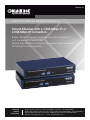
LR0301A-KIT 1-Port T1/E1 Ethernet Network Extender Kit Extend Ethernet with a 1.544-Mbps T1 or BLACK BOX 2.048-Mbps E1 connection. ® Bridges 10BASE-T/100BASE-TX Ethernet across full or Fractional T1 or E1 in unframed or framed mode. Ethernet Auto MDI/MDI-X function so no crossover cables are needed. DIP switches for easy configuration. • Customer Support Information Order toll-free in the U.S.: Call 877-877-BBOX (outside U.S. call 724-746-5500) • FREE technical support 24 hours a day, 7 days a week: Call 724-746-5500 or fax 724-746-0746 • Mailing address: Black Box Corporation, 1000 Park Drive, Lawrence, PA 15055-1018 • Web site: www.blackbox.com • E-mail: [email protected] 1-Port T1/E1 Ethernet Network Extender Kit Trademarks Used in this Manual Black Box and the Double Diamond logo are registered trademarks of BB Technologies, Inc. Any other trademarks mentioned in this manual are acknowledged to be the property of the trademark owners. We‘re here to help! If you have any questions about your application or our products, contact Black Box Tech Support at 724-746-5500 or go to blackbox.com and click on “Talk to Black Box.” You’ll be live with one of our technical experts in less than 30 seconds. Page 2 724-746-5500 | blackbox.com FCC and IC RFI Statements Federal Communications Commission and Industry Canada Radio Frequency Interference Statements This equipment generates, uses, and can radiate radio-frequency energy, and if not installed and used properly, that is, in strict accordance with the manufacturer’s instructions, may cause interference to radio communication. It has been tested and found to comply with the limits for a Class A computing device in accordance with the specifications in Subpart J of Part 15 of FCC rules, which are designed to provide reasonable protection against such interference when the equipment is operated in a commercial environment. Operation of this equipment in a residential area is likely to cause interference, in which case the user at his own expense will be required to take whatever measures may be necessary to correct the interference. Changes or modifications not expressly approved by the party responsible for compliance could void the user’s authority to operate the equipment. This digital apparatus does not exceed the Class A limits for radio noise emission from digital apparatus set out in the Radio Interference Regulation of Industry Canada. Le présent appareil numérique n’émet pas de bruits radioélectriques dépassant les limites applicables aux appareils numériques de la classe A prescrites dans le Règlement sur le brouillage radioélectrique publié par Industrie Canada. Page 3 1-Port T1/E1 Ethernet Network Extender Kit Normas Oficiales Mexicanas (NOM) Electrical Safety Statement INSTRUCCIONES DE SEGURIDAD 1. Todas las instrucciones de seguridad y operación deberán ser leídas antes de que el aparato eléctrico sea operado. 2. Las instrucciones de seguridad y operación deberán ser guardadas para referencia futura. 3. Todas las advertencias en el aparato eléctrico y en sus instrucciones de operación deben ser respetadas. 4. Todas las instrucciones de operación y uso deben ser seguidas. 5. El aparato eléctrico no deberá ser usado cerca del agua—por ejemplo, cerca de la tina de baño, lavabo, sótano mojado o cerca de una alberca, etc.. 6. El aparato eléctrico debe ser usado únicamente con carritos o pedestales que sean recomendados por el fabricante. 7. El aparato eléctrico debe ser montado a la pared o al techo sólo como sea recomendado por el fabricante. 8. Servicio—El usuario no debe intentar dar servicio al equipo eléctrico más allá a lo descrito en las instrucciones de operación. Todo otro servicio deberá ser referido a personal de servicio calificado. 9. El aparato eléctrico debe ser situado de tal manera que su posición no interfiera su uso. La colocación del aparato eléctrico sobre una cama, sofá, alfombra o superficie similar puede bloquea la ventilación, no se debe colocar en libreros o gabinetes que impidan el flujo de aire por los orificios de ventilación. 10. El equipo eléctrico deber ser situado fuera del alcance de fuentes de calor como radiadores, registros de calor, estufas u otros aparatos (incluyendo amplificadores) que producen calor. 11. El aparato eléctrico deberá ser connectado a una fuente de poder sólo del tipo descrito en el instructivo de operación, o como se indique en el aparato. 12. Precaución debe ser tomada de tal manera que la tierra fisica y la polarización del equipo no sea eliminada. 13. Los cables de la fuente de poder deben ser guiados de tal manera que no sean pisados ni pellizcados por objetos colocados sobre o contra ellos, poniendo particular atención a los contactos y receptáculos donde salen del aparato. 14. El equipo eléctrico debe ser limpiado únicamente de acuerdo a las recomendaciones del fabricante. 15. En caso de existir, una antena externa deberá ser localizada lejos de las lineas de energia. 16. El cable de corriente deberá ser desconectado del cuando el equipo no sea usado por un largo periodo de tiempo. 17. Cuidado debe ser tomado de tal manera que objectos liquidos no sean derramados sobre la cubierta u orificios de ventilación. 18. Servicio por personal calificado deberá ser provisto cuando: A: El cable de poder o el contacto ha sido dañado; u B: Objectos han caído o líquido ha sido derramado dentro del aparato; o C: El aparato ha sido expuesto a la lluvia; o D: El aparato parece no operar normalmente o muestra un cambio en su desempeño; o E: El aparato ha sido tirado o su cubierta ha sido dañada. Page 4 724-746-5500 | blackbox.com CE Statement European Community (CE) Electromagnetic Compatibility Directive This equipment has been tested and found to comply with the protection requirements of European Emission Standard EN55022/EN61000-3 and the Generic European Immunity Standard EN55024. EMC: EN55022(2003)/CISPR-2 (2002): Class A IEC61000-4-2 (2001): 4 KV CD, 8 KV AD IEC61000-4-3( 2002): 3 V/m IEC61000-4-4(2001): 1 KV (power line), 0.5 KV (signal line) Page 5 1-Port T1/E1 Ethernet Network Extender Kit 1. Specifications........................................................................................................................................................................................... 7 2. Overview . ............................................................................................................................................................................................. 8 2.1 Introduction.................................................................................................................................................................................... 8 2.2 Features.......................................................................................................................................................................................... 8 2.3 What’s Included.............................................................................................................................................................................. 8 2.4 LED Description............................................................................................................................................................................... 9 2.5 Front and Back Panels...................................................................................................................................................................... 9 3. Installation.............................................................................................................................................................................................10 4. DIP Switches...........................................................................................................................................................................................13 4.1 Definition of DIP Switches..............................................................................................................................................................13 4.2 Factory Default DIP Switch Configuration.......................................................................................................................................15 Page 6 724-746-5500 | blackbox.com Chapter 1: Specifications 1. Specifications Line Code: T1: AMI B8ZS; E1: AMI HDB3 Line Impedance: T1: 100 ohm; E1: 75, 120 ohm Line Rate: T1: 1.544 Mbps ± 32 ppm; E1: 2.048 Mbps ±50 ppm Frame Format: T1: ESF, SF, Unframed; E1: Framed, Unframed Standards: IEEE 802.3, IEEE 802.3u, EMI, Auto MDI/MDI-X, FCC Class A, CE Mark LAN Interface: Auto detection for 10BASE-T/100BASE-TX and full-/half-duplex Line Interface: T1: ANSI T1.403; E1: ITU-T G.703, G.704, ETSI ETR 152 Connectors: E1: (2) BNC; T1/E1: (1) RJ-48; Ethernet: (2) RJ-45; RS-232 console port: (1) DB9 F Indicators: (6) LEDs: Power, E1, T1, LOS, 10/100M, LAN Power: Input: 110/220 VAC, 50–60 Hz Temperature Tolerance: Operating: 32 to 122° F (0 to 50° C) Humidity Tolerance: 5 to 95% noncondensing Size: 1.7"H x 9.8"W x 5.9"D (4.3 x 25 x 15 cm) Page 7 1-Port T1/E1 Ethernet Network Extender Kit 2. Overview 2.1 Introduction The LR0301A 1-Port T1/ E1 Network Extender (LR0301A-KIT) is an Ethernet extender that converts protocols and data from Fractional T1/E1 to Ethernet 10BASE-T/100BASE-TX interfaces. It’s a symmetrical broadband solution for Intranet LAN-to-LAN connection with Nx64kbps bandwidth. The pair of extenders included with this kit acts as a bridge, enabling you to link two Ethernet networks across T1/E1. It supports T1/E1 framed and unframed modes with different line codes plus line build-out (LBO) capability. Because you are using leased lines provided by your telco, there are no distance limitations—you can extend your network anywhere you can get a T1 line. It’s ideal for various Ethernet LAN services (for example, videoconferencing, routing, etc.) through a fractional T1/E1 network. 2.2 Features • Supports Fractional T1/E1 framed and unframed modes • BNC connectors for E1 unbalanced 75 ohm • RJ-48 connector for E1 balanced 120 ohm and T1 balanced 100 ohm • Autosensing, autonegotiating for 10BASE-T/100BASE-TX and half-/full-duplex • Ethernet Auto MDI/MDI-X function for auto Tx/Rx swap so you don’t need a crossover cable • 6 LED indicators for status monitoring • DIP switches make configuration easy • Plug-and-play 2.3 What’s Included Your package should include the following items. If anything is missing or damaged, contact Black Box Technical Support at 724-746-5500. • (2) LR0301A 1-Port T1/ E1 Network Extenders • (2) Power cords • (2) CAT5e Ethernet cables • This user’s manual on CD-ROM Page 8 724-746-5500 | blackbox.com Chapter 2: Overview 2.4 LED Descriptions Table 2-1. Indicators. LED Color Function POWER Green Lit when power is on. E1 Green Lit when E1 is selected (SW1-1 is OFF). T1 Green Lit when T1 is selected (SW1-1 is ON). LOS Red Lit when signal is lost for selected E1/T1. 10/100M Green Lit when Ethernet is connected at 100 Mbps. Off when Ethernet is connected at 10 Mbps. LAN Green Lit when Ethernet is connected. Blinks when transmitting/receiving data. 2.5 Front and Back Panels Reset Button LED Indicators DIP Switches (SW1-1–SW1-8) DIP Switches (SW2-1–SW2-8) Figure 2-1. Front panel. Ethernet Port Power Input E1 BNC Interface Power Switch E1/T1 RJ-48 Interface Figure 2-2. Rear panel. Page 9 1-Port T1/E1 Ethernet Network Extender Kit 3. Installation The 1-Port T1/ E1 Network Extender uses DIP switches for fast and easy configuration, so it can be installed quickly. Follow the steps listed below to complete the installation and configuration. There are two external DIP switches on the front of the unit and four internal DIP switches on the circuit board inside the unit. You will use the external DIP switches for both full and Fractional T1/E1. You will only use the internal DIP switches for Fractional T1/E1 configuration. 1. Select the Fractional E1/ T1 interface configurations via SW1-1–SW1-7 DIP switches. The default setup is T1. The DIP switches are on the front panel. Refer to Figure 3-1 and Table 3-1 to see the DIP switches’ locations and definitions. Figure 3-1. SW1-1–SW1-7 DIP switches. NOTE: Table 3-1 describes DIP switches SW1-1–SW1-7. Tables 3-2 through 3-5 describe these switches in more detail. Table 3-5 also describes DIP switch SW2-1. Table 3-1. SW1-1–SW1-7 DIP switches. DIP Switches OFF ON Function SW1-1 E1 T1 E1/ T1 selection SW1-2 See Table 3-2 See Table 3-2 Impedance SW1-3 See Table 3-3 See Table 3-3 Frame Mode SW1-4 See Table 3-3 See Table 3-3 Frame Mode SW1-5 See Table 3-4 See Table 3-4 Line Code SW1-6 See Table 3-5 See Table 3-5 LBO SW1-7 See Table 3-5 See Table 3-5 LBO Table 3-2. Impedance configuration. Page 10 SW1-1 SW1-2 Impedance OFF ON 75 ohm OFF OFF 120 ohm ON OFF 100 ohm ON ON 100 ohm 724-746-5500 | blackbox.com Chapter 3: Installation Table 3-3. Frame mode configuration. SW1-1 SW1-3 SW1-4 Frame Mode OFF OFF OF E1 Unframed OFF ON OFF E1 CRC4 OFF OF ON E1 CAS OFF ON ON E1 CRC4+CAS ON OFF OFF T1 Unframed ON ON OFF T1 SF ON OFF ON T1 ESF Table 3-4. Line code configuration. SW1-1 SW1-5 Line Code OFF OFF HDB3 OFF ON AMI ON OFF B8ZS ON ON AMI Table 3-5. DS-1 LBO and DSX-1 transmit pulse template. SW1-1 SW1-6 SW1-7 SW1-8 SW2-1 E1 or DS1/DSX-1 LBO OFF X X X X E1 ON OFF OFF OFF OFF DS-1, 0 dB, LBO ON ON OFF OFF OFF DS-1, 7.5 dB, LBO ON OFF ON OFF OFF DS-1, 15 dB, LBO ON ON ON OFF OFF DS-1, 22.5 dB, LBO ON X X ON OFF DSX-1, 0–133 feet ON X X OFF ON DSX-1, 133–266 feet ON OFF OFF ON ON DSX-1, 266–399 feet ON ON OFF ON ON DSX-1, 399–533 feet ON X ON ON ON DSX-1, 533–655 feet Page 11 1-Port T1/E1 Ethernet Network Extender Kit 2. Connect the T1/E1 line to the BNC or RJ-48 connectors on the back panel. Figure 3-2 describes the RJ-48 pin assignment. Pin 4 and Pin 5 (to input of demarc) Pin 1 and Pin 2 (to output of demarc) Figure 3-2. RJ-48 port pin assignment. 3. Connect the Ethernet cable to the RJ-45 LAN connector. 4. Connect the power cord to the AC outlet and turn on the power switch. 5. The T1/E1 and LAN LED indicators will light and the LAN indicator will flash to show the Ethernet data activity. The LOS LED indicator will light RED when E1/T1 is in Loss of Signal. Page 12 724-746-5500 | blackbox.com Chapter 4: DIP Switches 4. DIP Switches 4.1 Definition of DIP switches Table 4-1 describes the DIP switches that are located on the extender’s front panel. You will use these switches for either full or Fractional T1/E1. Table 4-1. Description of DIP switches for full or Fractional T1/E1. DIP Switches OFF ON Function SW1-1 E1 T1 T1/E1 selection SW1-2 See Table 3-2 See Table 3-2 Impedance SW1-3 See Table 3-3 See Table 3-3 Frame Mode SW1-4 See Table 3-3 See Table 3-3 Frame Mode SW1-5 See Table 3-4 See Table 3-4 Line Code SW1-6 See Table 3-5 See Table 3-5 LBO SW1-7 See Table 3-5 See Table 3-5 LBO SW1-8 See Table 3-5 See Table 3-5 DSX-1 SW2-1 See Table 3-5 See Table 3-5 DSX-1 SW2-2 Reserved Reserved Reserved SW2-3 Reserved Reserved Reserved SW2-4 Reserved Reserved Reserved SW2-5 Nx64 Nx56(T1 only) 64K/56K Channel SW2-6 Full E1/T1 Fractional E1/T1 Fractional SW2-7 All zeros All ones Stuff bits SW2-8 Internal External E1/T1 Clock Mode Page 13 1-Port T1/E1 Ethernet Network Extender Kit The SW4-1–4-8, SW5-1–5-8, SW6-1–6-8, SW7-1–7-8 DIP switches are on the PC board. You need to open the top of the case to configure these DIP switches. Refer to the Figure 4-1 to see the DIP switches’ locations. DIP switch “ON” means selected, and “OFF” means unselected. NOTE: SW4-1–4-8, SW5-1–5-8, SW6-1–6-8, and SW7-1–7-8 DIP switches are active only in Fractional T1 or Fractional E1 mode. Tables 4-2 and 4-3 describe their functions. Figure 4-1. SW4-1–4-8, SW5-1–5-8, SW6-1–6-8, and SW7-1–7-8 DIP switches. Table 4-2. Fractional T1 (24 channels) selections. Fractional T1 SW4-1 SW4-2 SW4-3 SW4-4 SW4-5 SW4-6 SW4-7 SW4-8 Channel No. 1 2 3 4 5 6 7 8 SW5-1 SW5-2 SW5-3 SW5-4 SW5-5 SW5-6 SW5-7 SW5-8 9 10 11 12 13 14 15 16 SW6-1 SW6-2 SW6-3 SW6-4 SW6-5 SW6-6 SW6-7 SW6-8 17 18 19 20 21 22 23 24 Channel No. Channel No. Page 14 724-746-5500 | blackbox.com Chapter 4: DIP Switches Table 4-3. Fractional E1 (31 channels) selections. Fractional E1 SW4-1 SW4-2 SW4-3 SW4-4 SW4-5 SW4-6 SW4-7 SW4-8 Channel No. OFF 2 3 4 5 6 7 8 SW5-1 SW5-2 SW5-3 SW5-4 SW5-5 SW5-6 SW5-7 SW5-8 9 10 11 12 13 14 15 16 SW6-1 SW6-2 SW6-3 SW6-4 SW6-5 SW6-6 SW6-7 SW6-8 17 18 19 20 21 22 23 24 SW7-1 SW7-2 SW7-3 SW7-4 SW7-5 SW7-6 SW7-7 SW7-8 25 26 27 28 29 30 31 32 Channel No. Channel No. Channel No. NOTE: SW4-1 (Channel 1) is NOT available, and must be set to“OFF”. SW6-1 (Channel 17) can be selected “ON” only when E1 CRC4 framing mode is selected. SW4–SW7 DIP switches defaults are set to “OFF.” 4.2 Factory Default DIP Switch Configuration The factory default DIP switches setting are shown in Table 4-4. Before you change any settings, make sure every parameter and all the configurations for both pairs of T1/E1 Ethernet Network Extenders are the same. Call Black Box Tech Support for details. Table 4-4. Factory default configuration. DIP Switches ON/OFF DIP Switches ON/OFF SW1-1 ON (T1) SW2-1 OFF SW1-2 OFF (100 ohm) SW2-2 OFF SW1-3 OFF (Unframed) SW2-3 OFF SW1-4 OFF (Unframed) SW2-4 OFF SW1-5 OFF (B8ZS) SW2-5 OFF (Nx64) SW1-6 OFF (DS1) SW2-6 OFF (Full T1) SW1-7 OFF (0 db) SW2-7 OFF (All zeros) SW1-8 OFF (LBO) SW2-8 OFF (Internal) Page 15 Black Box Tech Support: FREE! Live. 24/7. Tech support the way it should be. Great tech support is just 30 seconds away at 724-746-5500 or blackbox.com. About Black Box Black Box Network Services is your source for an extensive range of networking and infrastructure products. You’ll find everything from cabinets and racks and power and surge protection products to media converters and Ethernet switches all supported by free, live 24/7 Tech support available in 30 seconds or less. © Copyright 2011. All rights reserved. LR0301A-KIT, version 2 724-746-5500 | blackbox.com