1
OWNER’S MANUAL
Thank you, and congratulations on your choice of the Roland XP-30 64 Voice Expandable
Synthesizer.
Before using this unit, carefully read the sections entitled: “IMPORTANT SAFETY
INSTRUCTIONS” (p. 2), “USING THE UNIT SAFELY” (p. 3), and “IMPORTANT
NOTES” (p. 5). These sections provide important information concerning the proper
operation of the unit. Additionally, in order to feel assured that you have gained a good
grasp of every feature provided by your new unit, Owner’s manual should be read in
its entirety. The manual should be saved and kept on hand as a convenient reference.
*
*
*
*
*
Apple is a registered trademark of Apple Computer, Inc.
Macintosh is a registered trademark of Apple Computer, Inc.
IBM is a registered trademark of International Business Machines Corporation.
IBM PC is a registered trademark of International Business Machines Corporation.
SmartMedia is a trademark of Toshiba Corporation.
Copyright © 1999 ROLAND CORPORATION
All rights reserved. No part of this publication may be reproduced in any form without the
written permission of ROLAND CORPORATION.
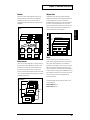
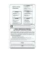
The lightning flash with arrowhead symbol, within an
equilateral triangle, is intended to alert the user to the
presence of uninsulated “dangerous voltage” within the
product’s enclosure that may be of sufficient magnitude to
constitute a risk of electric shock to persons.
CAUTION
RISK OF ELECTRIC SHOCK
DO NOT OPEN
ATTENTION: RISQUE DE CHOC ELECTRIQUE NE PAS OUVRIR
CAUTION: TO REDUCE THE RISK OF ELECTRIC SHOCK,
DO NOT REMOVE COVER (OR BACK).
NO USER-SERVICEABLE PARTS INSIDE.
REFER SERVICING TO QUALIFIED SERVICE PERSONNEL.
The exclamation point within an equilateral triangle is
intended to alert the user to the presence of important
operating and maintenance (servicing) instructions in the
literature accompanying the product.
INSTRUCTIONS PERTAINING TO A RISK OF FIRE, ELECTRIC SHOCK, OR INJURY TO PERSONS.
IMPORTANT SAFETY INSTRUCTIONS
SAVE THESE INSTRUCTIONS
WARNING - When using electric products, basic precautions should always be followed, including the following:
1.
2.
3.
4.
5.
6.
7.
8.
9.
Read these instructions.
Keep these instructions.
Heed all warnings.
Follow all instructions.
Do not use this apparatus near water.
Clean only with a dry cloth.
Do not block any of the ventilation openings. Install in
accordance with the manufacturers instructions.
Do not install near any heat sources such as radiators,
heat registers, stoves, or other apparatus (including
amplifiers) that produce heat.
Do not defeat the safety purpose of the polarized or
grounding-type plug. A polarized plug has two blades with
one wider than the other. A grounding type plug has two
blades and a third grounding prong. The wide blade or the
third prong are provided for your safety. When the provided
plug does not fit into your outlet, consult an electrician for
replacement of the obsolete outlet.
10. Protect the power cord from being walked on or pinched
particularly at plugs, convenience receptacles, and the
point where they exit from the apparatus.
11. Only use attachments/accessories specified by the
manufacturer.
12. Never use with a cart, stand, tripod, bracket,
or table except as specified by the
manufacturer, or sold with the apparatus.
When a cart is used, use caution when
moving the cart/apparatus combination to
avoid injury from tip-over.
13. Unplug this apparatus during lightning storms or when
unused for long periods of time.
14. Refer all servicing to qualified service personnel. Servicing
is required when the apparatus has been damaged in any
way, such as power-supply cord or plug is damaged, liquid
has been spilled or objects have fallen into the apparatus,
the apparatus has been exposed to rain or moisture, does
not operate normally, or has been dropped.
For the U.K.
IMPORTANT: THE WIRES IN THIS MAINS LEAD ARE COLOURED IN ACCORDANCE WITH THE FOLLOWING CODE.
BLUE:
NEUTRAL
BROWN: LIVE
As the colours of the wires in the mains lead of this apparatus may not correspond with the coloured markings identifying
the terminals in your plug, proceed as follows:
The wire which is coloured BLUE must be connected to the terminal which is marked with the letter N or coloured BLACK.
The wire which is coloured BROWN must be connected to the terminal which is marked with the letter L or coloured RED.
Under no circumstances must either of the above wires be connected to the earth terminal of a three pin plug.
CAUTION: Danger of explosion if battery is incorrectly replaced.
Replace only with same or equivalent type.
2
Used for instructions intended to alert
the user to the risk of death or severe
injury should the unit be used
improperly.
Used for instructions intended to alert
the user to the risk of injury or material
damage should the unit be used
improperly.
* Material damage refers
other adverse effects
respect to the home
furnishings, as well
animals or pets.
to damage or
caused with
and all its
to domestic
001
• Before using this unit, make sure to read the
instructions below, and the Owner’s Manual.
..........................................................................................................
002b
• Do not open or perform any internal modifications
on the unit. (The only exception would be where
this manual provides specific instructions which
should be followed in order to put in place userinstallable options; see p. 17, 21.)
..........................................................................................................
006
• When using the unit with a rack or stand recommended by Roland, the rack or stand must be
carefully placed so it is level and sure to remain
stable. If not using a rack or stand, you still need to
make sure that any location you choose for placing
the unit provides a level surface that will properly
support the unit, and keep it from wobbling.
..........................................................................................................
008e
• Use only the attached power-supply cord.
..........................................................................................................
009
• Avoid damaging the power cord. Do not bend it
excessively, step on it, place heavy objects on it,
etc. A damaged cord can easily become a shock or
fire hazard. Never use a power cord after it has
been damaged.
..........................................................................................................
013
• In households with small children, an adult
should provide supervision until the child is
capable of following all the rules essential for the
safe operation of the unit.
..........................................................................................................
014
• Protect the unit from strong impact.
The
symbol alerts the user to important instructions
or warnings.The specific meaning of the symbol is
determined by the design contained within the
triangle. In the case of the symbol at left, it is used for
general cautions, warnings, or alerts to danger.
The
symbol alerts the user to items that must never
be carried out (are forbidden). The specific thing that
must not be done is indicated by the design contained
within the circle. In the case of the symbol at left, it
means that the unit must never be disassembled.
The ● symbol alerts the user to things that must be
carried out. The specific thing that must be done is
indicated by the design contained within the circle. In
the case of the symbol at left, it means that the powercord plug must be unplugged from the outlet.
015
• Do not force the unit’s power-supply cord to share
an outlet with an unreasonable number of other
devices. Be especially careful when using
extension cords—the total power used by all
devices you have connected to the extension cord’s
outlet must never exceed the power rating (watts/
amperes) for the extension cord. Excessive loads
can cause the insulation on the cord to heat up and
eventually melt through.
..........................................................................................................
016
• Before using the unit in a foreign country, consult
with your retailer, the nearest Roland Service
Center, or an authorized Roland distributor, as
listed on the “Information” page.
..........................................................................................................
022a
• Always turn the unit off and unplug the power
cord before attempting installation of the circuit
board (SR-JV80 series).
..........................................................................................................
023
• DO NOT play a CD-ROM disc on a conventional
audio CD player. The resulting sound may be of a
level that could cause permanent hearing loss.
Damage to speakers or other system components
may result.
..........................................................................................................
(Do not drop it!)
..........................................................................................................
3
USING THE UNIT SAFELY
102b
• Always grasp only the plug on the power-supply
cord when plugging into, or unplugging from, an
outlet or this unit.
..........................................................................................................
104
• Try to prevent cords and cables from becoming
entangled. Also, all cords and cables should be
placed so they are out of the reach of children.
..........................................................................................................
106
• Never climb on top of, nor place heavy objects on
the unit.
..........................................................................................................
107b
• Never handle the power cord or its plugs with wet
hands when plugging into, or unplugging from,
an outlet or this unit.
..........................................................................................................
108a
• Before moving the unit, disconnect the power plug
from the outlet, and pull out all cords from
external devices.
..........................................................................................................
109a
• Before cleaning the unit, turn off the power and
unplug the power cord from the outlet.
..........................................................................................................
110a
• Whenever you suspect the possibility of lightning
in your area, pull the plug on the power cord out
of the outlet.
..........................................................................................................
115a
• Install only the specified circuit board(s) (SR-JV80
series). Remove only the specified screws (p. 17,
21).
..........................................................................................................
4
Important Notes
In addition to the items listed under “IMPORTANT SAFETY
INSTRUCTIONS” and “USING THE UNIT SAFELY” on
pages 2 and 3, please read and observe the following:
Power Supply
• Do not use this unit on the same power circuit with any
device that will generate line noise (such as an electric
motor or variable lighting system).
• Before connecting this unit to other devices, turn off the
power to all units. This will help prevent malfunctions
and/or damage to speakers or other devices.
Placement
• Using the unit near power amplifiers (or other equipment
containing large power transformers) may induce hum. To
alleviate the problem, change the orientation of this unit;
or move it farther away from the source of interference.
• This device may interfere with radio and television
reception. Do not use this device in the vicinity of such
receivers.
• Do not expose the unit to direct sunlight, place it near
devices that radiate heat, leave it inside an enclosed
vehicle, or otherwise subject it to temperature extremes.
Excessive heat can deform or discolor the unit.
• To avoid possible breakdown, do not use the unit in a wet
area, such as an area exposed to rain or other moisture.
Maintenance
• For everyday cleaning wipe the unit with a soft, dry cloth
or one that has been slightly dampened with water. To
remove stubborn dirt, use a cloth impregnated with a
mild, non-abrasive detergent. Afterwards, be sure to
wipe the unit thoroughly with a soft, dry cloth.
Additional Precautions
• Please be aware that the contents of memory can be
irretrievably lost as a result of a malfunction, or the
improper operation of the unit. To protect yourself against
the risk of loosing important data, we recommend that
you periodically save a backup copy of important data
you have stored in the unit’s memory on a memory card.
• Unfortunately, it may be impossible to restore the
contents of data that was stored in the unit’s memory, a
memory card or another MIDI device (e.g., a sequencer)
once it has been lost. Roland Corporation assumes no
liability concerning such loss of data.
• Use a reasonable amount of care when using the unit’s
buttons, sliders, or other controls; and when using its
jacks and connectors. Rough handling can lead to
malfunctions.
• Never strike or apply strong pressure to the display.
• When connecting / disconnecting all cables, grasp the
connector itself—never pull on the cable. This way you
will avoid causing shorts, or damage to the cable’s
internal elements.
• A small amount of heat will radiate from the unit during
normal operation.
• To avoid disturbing your neighbors, try to keep the unit’s
volume at reasonable levels. You may prefer to use
headphones, so you do not need to be concerned about
those around you (especially when it is late at night).
• When you need to transport the unit, package it in the box
(including padding) that it came in, if possible. Otherwise,
you will need to use equivalent packaging materials.
• Use only the specified expression pedal (EV-5; sold
separately). By connecting any other expression pedals,
you risk causing malfunction and/or damage to the unit.
• Never use benzine, thinners, alcohol or solvents of any kind,
to avoid the possibility of discoloration and/or deformation.
Before Using Memory Cards
Repairs and Data
Using Memory Cards
• Please be aware that all data contained in the unit’s
memory may be lost when the unit is sent for repairs.
Important data should always be backed up memory
card, or written down on paper (when possible). During
repairs, due care is taken to avoid the loss of data.
However, in certain cases (such as when circuitry related
to memory itself is out of order), we regret that it may not
be possible to restore the data, and Roland assumes no
liability concerning such loss of data.
• Carefully insert the Memory card all the way in—until it
is firmly in place.
Memory Backup
• This unit contains a battery which powers the unit’s
memory circuits while the main power is off. When this
battery becomes weak, the message shown below will
appear in the display. Once you see this message, have
the battery replaced with a fresh one as soon as possible
to avoid the loss of all data in memory. To have the
battery replaced, consult with your retailer, the nearest
Roland Service Center, or an authorized Roland
distributor, as listed on the “Information” page.
“Battery Low”
• Never touch the terminals of the Memory card. Also,
avoid getting the terminals dirty.
Handling CD-ROMs
• Avoid touching or scratching the shiny underside
(encoded surface) of the disc. Damaged or dirty CD-ROM
discs may not be read properly. Keep your discs clean
using a commercially available CD cleaner.
5
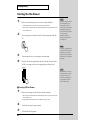
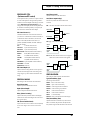
How to Read This Owner’s Manual
This owner’s manual is organized as follows.
Quick Start
Chapter 6. Getting the Full Potential of
the XP-30
This section is intended for those using the XP-30 for the first
time, and explains how to use various functions in a simple
way. Please read Quick Start and follow along by actually
operating the XP-30. This will help you understand most of
what you need to know for basic operations. More advanced
ways of using the XP-30 or details of other operations are
explained the Advanced Use section.
This chapter includes various techniques that expand the XP30’s operational scope. It includes use with external MIDI
devices, live performance applications and others.
Advanced Use
The Advanced Use section is divided into 6 chapters. But
before you start reading it, we’d like to suggest going
through the Quick Start section.
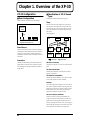
Chapter 1. Overview of the XP-30
This chapter covers XP-30 sound source section
configurations, as well as basic operation. Please be sure to
read this chapter in order to fully understand the XP-30.
Appendices
This chapter contains a troubleshooting section for use when
the XP-30 is not functioning as expected. There is also a list of
error messages that you can refer to if an error message
appears on the display. A list of parameters and MIDI
implementation chart are also provided.
■ Notation Used in This Owner’s
Manual
To make operation procedures easy to understand, the
following notation system is adopted:
Chapter 2. Playing
Characters and numbers in square brackets [ ] indicate
buttons on the front panel. For example, [PATCH] represents
the PATCH button and [ENTER] the ENTER button.
This chapter explains how to use the XP-30 in Patch,
Performance and Rhythm Set modes. Reading it is essential
for understanding XP-30 operational procedures.
An asterisk (*) at the beginning of a paragraph indicates a
note or precaution. These should not be ignored. In the Quick
Start section, such material is indicated by (
).
Chapter 3. Creating Your Own Sounds
(p. **) refers to pages within the manual.
This chapter covers creating sounds, the parameters that make
up a Patch, Performance, or Rhythm Set, and the System
parameters that determine global XP-30 operation, as well as
their functions. Comprehending the information in the
chapter is an essential prerequisite before creating your own
sounds.
In this manual, when any particular parameter is referred to,
the name of the parameter is given, and this is then followed
(in parenthesis) by information detailing its mode, display
group, and display. For example: Key Mode parameter
(PERFORM/COMMON/PERFORM COMMON).
Chapter 4. Memory Settings
(Utility/Card Mode)
This chapter goes over the various Utility functions such as
storing Patch, Performance or Rhythm Set data, clearing the
internal memory, etc. Being familiar with these will
streamline operation procedures.
Chapter 5. Using the XP-30 as the GM
Sound Module
This chapter explains needed procedures and parameters for
using the XP-30 as a General MIDI System-compatible sound
source. Read this chapter before attempting to play back
commercial General MIDI System score data.
6
* The display screens printed in this owner’s manual are based on
the factory settings. However, please be aware that in some cases
they may differ from the actual factory settings.
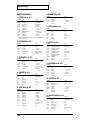
Contents
Main Features........................................................................................11
Front and Rear Panel............................................................................12
Quick Start ........................................................ 15
Getting Ready........................................................................................16
Installing the Wave Expansion Board ................................................................................................... 16
Cautions When Installing an Wave Expansion Board............................................................. 16
Installation de la carte d’extension Wave (French language for Canadian Safety Standard) ....... 20
Precautions lors de l’installation de la carte d’extension Wave ............................................. 20
Making Connections ................................................................................................................................ 24
Turning On the Power ............................................................................................................................. 26
Turning Off the Power ................................................................................................................. 26
Reset to Default Factory Settings (Factory Reset) ................................................................................ 27
Listening to the Demo Song ................................................................28
Profile of the Composer ............................................................................................................... 29
Playing the Sounds...............................................................................30
Selecting Patches and Playing the Sounds............................................................................................ 30
Selecting Wave Expansion Patches........................................................................................................ 31
Selecting Patches by Category (Patch Search Function) ..................................................................... 32
Auditioning the Patches (Phrase Preview) ........................................................................................... 33
Try Out Performance Functions............................................................................................................. 34
Velocity/Aftertouch ..................................................................................................................... 34
Pitch Bend/Modulation Lever .................................................................................................... 34
C1–C4 Slider................................................................................................................................... 34
Hold Pedal...................................................................................................................................... 35
Expression Pedal ........................................................................................................................... 35
Solo .................................................................................................................................................. 35
Portamento..................................................................................................................................... 35
Sound Palette ................................................................................................................................. 36
Play Arpeggios (Arpeggiator) ................................................................................................................ 36
Play Percussion Sounds from the Keyboard ........................................................................................ 38
Advanced Use ................................................... 39
Chapter 1. Overview of the XP-30........................................................40
XP-30 Configuration................................................................................................................................. 40
Basic Configuration....................................................................................................................... 40
Classification of XP-30 Sound Types.......................................................................................... 40
Number of Simultaneous Voices ................................................................................................ 42
Basic Operation......................................................................................................................................... 42
Switching Modes........................................................................................................................... 42
About the Function Buttons ........................................................................................................ 43
About the Cursor Buttons............................................................................................................ 44
Modifying a Value ........................................................................................................................ 45
Assigning a Name ......................................................................................................................... 46
7
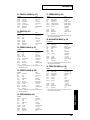
Contents
Chapter 2. Playing.................................................................................47
Playing in Patch Mode............................................................................................................................. 47
Selecting a Patch ............................................................................................................................ 47
Using Phrase Preview to Play Patches....................................................................................... 49
Making a Patch Sound Thick or Thin (Turning a Tone On/Off) ........................................... 50
Playing Single Notes (Solo) ......................................................................................................... 50
Creating Smooth Pitch Changes (Portamento) ......................................................................... 50
Using the Sliders to Modify the Sound in Realtime (Sound Palette Function).................... 50
Playing in Performance Mode ................................................................................................................ 51
Selecting a Performance ............................................................................................................... 51
Playing Fatter and Richer Sounds by Combining Patches (Layer)........................................ 52
Splitting the Keyboard to Play Separate Patches in Different Sections (Split)..................... 52
Playing Along with a Song Playback (XP-30 Used as a Multitimbral Sound Source) ........ 53
Assigning a Different Patch to a Part ......................................................................................... 54
Using the Sliders to Modify the Sound in Realtime (Sound Palette Function).................... 54
Playing in Rhythm Set Mode .................................................................................................................. 55
Selecting a Rhythm Set ................................................................................................................. 55
Playing Percussion Instruments ................................................................................................. 56
Playing an Arpeggio ................................................................................................................................ 56
Playing an Arpeggio Over a Preset Keyboard Area ................................................................ 57
Holding an Arpeggio.................................................................................................................... 58
Simulating a Guitar Cutting Technique..................................................................................... 58
Playing an Arpeggio from an External MIDI Device............................................................... 58
Creating an Arpeggio Pattern ..................................................................................................... 58
Convenient Functions for Performance ................................................................................................ 59
Transposing the Keyboard in Octave Units (Octave Shift)..................................................... 59
Transposing the Keyboard in Semitone Steps (Transpose) .................................................... 60
If “Stuck” Notes Occur or a Note Does Not Sound (Panic) .................................................... 60
Chapter 3. Creating Your Own Sounds...............................................61
Regarding Effects...................................................................................................................................... 61
How Effects Units Work in Different Modes ............................................................................ 61
Turning Effects On/Off................................................................................................................ 62
Sound Editing Procedures....................................................................................................................... 62
Editing a Patch............................................................................................................................... 62
Editing a Performance .................................................................................................................. 65
Editing a Rhythm Set.................................................................................................................... 66
Keeping Edited Sound ............................................................................................................................. 67
Memory and Data Storage ........................................................................................................... 67
Storing a Sound You Modify into User Memory ..................................................................... 68
Functions of Patch Parameters ............................................................................................................... 68
Settings Common to the Entire Patch (COMMON)................................................................. 68
Setting Effects for a Patch (EFFECTS) ........................................................................................ 71
Using Controllers to Change How Sounds Are Played (CONTROL)................................... 73
Modifying Waveform (WAVE)................................................................................................... 76
Modulating Sounds (LFO) ........................................................................................................... 78
Modifying Pitch (PITCH)............................................................................................................. 79
Modifying the Brightness of Sound with a Filter (TVF).......................................................... 80
Changing the Sound’s Volume and Stereo Location (TVA) ................................................... 81
Functions of Performance Parameters................................................................................................... 83
Settings Common to the Entire Performance (COMMON) .................................................... 83
Setting Effects for a Performance (EFFECTS) ........................................................................... 84
Making MIDI Settings for a Part (MIDI).................................................................................... 86
Making Settings for Each Part (PART)....................................................................................... 87
Confirming MIDI Information for Each Part (INFO) .............................................................. 87
Functions of Rhythm Set Parameters .................................................................................................... 88
Naming a Rhythm Set (COMMON)........................................................................................... 88
8
Contents
Setting Effects for a Rhythm Tone (EFFECTS).......................................................................... 88
Controlling How a Rhythm Tone will Sound with Controllers (CONTROL) ..................... 90
Modifying Waveform of a Rhythm Tone (WAVE) .................................................................. 90
Modifying Pitch of a Rhythm Tone (PITCH) ............................................................................ 91
Changing the Tone (Filter) of a Rhythm Tone (TVF)............................................................... 91
Changing the Volume and Stereo Location of a Rhythm Tone (TVA).................................. 92
Multi-Effects Types (EFX Parameter) .................................................................................................... 93
XP-30 Operating Environment Setup (System Parameters and Their Functions) ........................ 108
Display Screen Contrast and Clock Settings (SETUP)........................................................... 108
Arpeggio Settings (ARPEGGIO)............................................................................................... 108
Keyboard and Controllers Settings (CONTROL)................................................................... 110
MIDI Settings (MIDI).................................................................................................................. 112
Phrase Preview Settings (PREVIEW) ....................................................................................... 113
Adjusting Tuning (TUNE) ......................................................................................................... 113
Program Change (PGM CHNG) ............................................................................................... 114
Checking Things Such as the Installation Status of Wave Expansion Boards (INFO)...... 114
Chapter 4. Memory Settings (Utility/Card Mode) .............................115
About Utility/Card Mode..................................................................................................................... 115
Basic Procedure in Utility/Card Mode ............................................................................................... 115
Storing Sound Data in User Memory (WRITE).................................................................................. 116
Performance Write ...................................................................................................................... 116
Patch Write................................................................................................................................... 116
Rhythm Set Write ........................................................................................................................ 116
Copying Sound Source Settings (COPY) ............................................................................................ 117
Performance Copy ...................................................................................................................... 117
Patch Copy ................................................................................................................................... 117
Rhythm Set Copy ........................................................................................................................ 118
Initializing Sound Source Settings (INIT) ........................................................................................... 119
Performance Initialize................................................................................................................. 119
Patch Initialize ............................................................................................................................. 119
Rhythm Set Initialize .................................................................................................................. 119
Transmitting Sound Settings (XFER)................................................................................................... 119
Transmitting Data to an External MIDI Device...................................................................... 119
Transmitting Data to User Memory ......................................................................................... 120
Preventing User Memory Writing Operation (PROTECT) .............................................................. 121
Memory Card-Related Settings (CARD)............................................................................................. 121
Formatting the Memory Card for the XP-30 (FORMAT) ...................................................... 122
Renaming a File (RENAME)...................................................................................................... 122
Deleting Unwanted Files (DELETE)......................................................................................... 122
Checking the Contents Memory Card (INFO)........................................................................ 122
Loading a File from Memory Card into the XP-30 (LOAD)............................................................. 122
Saving Data to Memory Card (SAVE)................................................................................................. 122
Recalling Factory Default Settings (FACTORY RESET) ................................................................... 123
Chapter 5. Using the XP-30 as the GM Sound Module ....................124
Entering GM Mode................................................................................................................................. 124
Initializing the Sound Source for GM System Basic Settings ............................................... 124
Playing Back a GM Score ........................................................................................................... 124
Modifying GM Mode Settings .............................................................................................................. 125
Making Effects Settings in GM Mode (EFFECTS) .................................................................. 125
Setting a Part (PART).................................................................................................................. 127
Confirming MIDI Information of Each Part (INFO) .............................................................. 127
Convenient Functions in GM Mode (GM Utility) ............................................................................. 127
Copying Effects Settings (COPY).............................................................................................. 128
Initializing GM Mode (INIT) ..................................................................................................... 128
Transmitting GM Mode Settings (XFER)................................................................................. 128
9
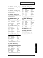
Contents
Chapter 6. Getting the Full Potential of the XP-30 ...........................129
Techniques for Using Patches............................................................................................................... 129
Reinforcing Filter Characteristics ............................................................................................. 129
Making the Up-Beat Note Sound at the Same Time You Play a Down-Beat Note ........... 129
Holding a Note with Modulation Retained ............................................................................ 129
Syncing the LFO Cycle to System Tempo ............................................................................... 129
Modifying Multi-Effects to Match the System’s Tempo........................................................ 130
Using a Pedal Switch to Modify the Rotary Speed of the Rotary Effect ............................. 130
Playing Phrase Loops at a System’s Tempo............................................................................ 130
Using the Slider to Pan Sounds in Real Time ......................................................................... 131
Using the XP-30 to Play Live ................................................................................................................ 131
Changing Multiple Sounds of an External MIDI Device Simultaneously.......................... 131
Changing Sounds with a Pedal Switch .................................................................................... 131
Using External MIDI Devices ............................................................................................................... 132
Using the XP-30 to Control External MIDI Devices............................................................... 132
Playing the XP-30’s Sound Source from an External MIDI Device ..................................... 132
Selecting XP-30 Sounds from an External MIDI Device........................................................ 132
Enjoying Desktop Music ....................................................................................................................... 134
Connecting to Your Computer.................................................................................................. 134
Disconnecting the Keyboard from the Internal Sound Source (Local OFF) ....................... 137
Appendices...................................................... 139
Troubleshooting..................................................................................140
Error Messages ...................................................................................142
Quick Reference of Procedures ........................................................143
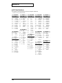
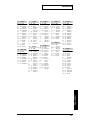
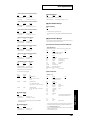
Parameter List .....................................................................................147
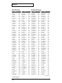
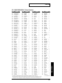
Waveform List .....................................................................................160
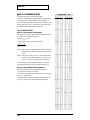
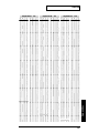
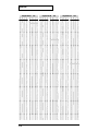
Patch List.............................................................................................168
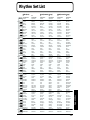
Rhythm Set List...................................................................................177
Performance List.................................................................................181
Arpeggio Style List .............................................................................182
MIDI Implementation...........................................................................183
Specifications......................................................................................207
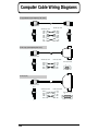
Computer Cable Wiring Diagrams.....................................................208
Index.....................................................................................................209
10
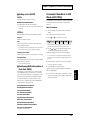
Main Features
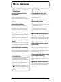
■ High-Performance Synthesizer
Sound Source
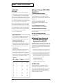
64-Voice Polyphony and 16-Part
Multitimbrality
The XP-30 is a 16-part multitimbral sound source that
produces up to 64 simultaneous polyphonic notes.
Effectively used with an external sequencer or computer, the
XP-30’s true creative potential for music production becomes
apparent (p. 41).
Powerful Onboard Effects
Advanced DSP (Digital Signal Processor) technology
provides a wide array of studio quality effects. In addition to
the Multi-Effects (EFX) section that features 40 different
types of effects, the XP-30 also features an independent
chorus unit and reverb unit (p. 61).
■ Expandability
Allows Two Wave Expansion Boards
to be Installed at the Same Time
Up to two SR-JV80 series Wave Expansion Boards can be
installed simultaneously, allowing you to expand the range
of available sounds (p. 16, 20).
Data from Popular Wave Expansion
Boards Already Onboard
The data of the three popular Wave Expansion Boards, the
SR-JV80-02 “Orchestral,” SR-JV80-09 “Session,” and SR-JV8011 “Techno Collection” is onboard.
This means that for practical purposes, you can have
simultaneous access to the sounds of up to five Wave
Expansion Boards, and can draw on a vast quantity of
waveform data as material for creating your sounds.
Extensive Tone Structure Range
■ Quick and Intuitive Operation
Ten different Structures are available for combining basic
sound elements for more flexible sound making. A ring
modulator and booster enhance creating sounds (p. 70).
Enhanced Operational Ease
An Array of Arpeggio and Cutting
Options
With the [ARPEGGIO] on, you can create various arpeggios
and simulate cutting techniques simply by pressing a chord.
You can even specify the rhythmical “feel” you want (p. 56).
General MIDI System Compatibility
The XP-30 provides a mode compatible with the General
MIDI System, the standard format for desktop music (DTM)
systems, and can play back commercially available General
MIDI System compatible song data (p. 124).
General MIDI System
The General MIDI system is a set of recommendations
which seeks to provide a way to go beyond the
limitations of proprietary designs, and standardize the
MIDI capabilities of sound generating devices. Sound
generating devices and music files that meets the
General MIDI standard bears the General MIDI logo
(
). Music files bearing the General MIDI logo can be
played back using any General MIDI sound generating
unit to produce essentially the same musical
performance.
Dedicated buttons are provided for each function to simplify
operation. The group of function buttons located below the
display allow intuitive editing (p. 43).
Featuring the Patch Search and Phrase
Preview Functions that were Popular
on the JV-2080
The Patch Search function (p. 32, 48) lets you rapidly find the
patch you want simply by specifying a patch category. By
pressing [PHRASE PREVIEW], you can then hear the
selected patch play a phrase suitable for that type of patch.
(Phrase Preview function, p. 33, 49)
Use the Sound Palette Sliders to Make
Quick Changes in the Sound
The four sliders in the PALETTE section let you make
realtime changes in tone and volume while you play (p. 36,
50, 54).
■ Computer Interface Connector
A special computer cable makes it easy for you to connect the
XP-30 to your computer, so that you can enjoy ensemble
playing (p. 134).
11
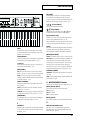
Front and Rear Panel
A
B
C
D
E
H
■ Front Panel
A
Volume Slider
This slider adjusts the overall volume that is output from the
rear panel OUTPUT jacks and PHONES jack. →p. 26
B
PALETTE Section
[+OCT], [-OCT]
These buttons adjust the pitch of the keyboard in octave steps. →p. 59
Pressing either of these buttons while holding down [TRANSPOSE]
allows you to set the desired amount of transposition. →p. 60
D
MODE Section
The buttons in this section select modes. The button indicator
of the selected mode will light. →p. 42
Use the four sliders to modify sounds in real time.
[PERFORM]/[GM]
[FILTER/ENV]
Pressed to get into Performance mode. Hold down [SHIFT]
while you press [PERFORM] to select GM mode. →p. 51, 124
Press this button ON when modifying filter and/or envelope
settings in real time using the four sliders (CUTOFF/RESO./
ATTACK/DECAY). →p. 36, 51, 54
[LEVEL]
Press this button ON when adjusting volume balance in real
time using the four sliders (1/2/3/4). →p. 36, 51, 54
[PATCH]/[PART]
Pressed to get into Patch mode. By holding down [PERFORM]
and pressing [PATCH], you can modify the settings of the patch
that is assigned to each part of the performance. →p. 47, 54, 66
[SYSTEM]
[CONTROLLER]
This selects System mode. →p. 108
Can be switched on when you wish to assign various
parameters to the four sliders, and modify the sound as you
play (C1/C2/C3/C4). →p. 34
[RHYTHM]
C
This selects Utility/Card mode. →p. 115
KEY EFFECTS Section
The buttons in this section allow you to assign various
functions to the keys of the XP-30’s keyboard.
[PORTAMENTO]
Switches Portamento on/off. →p. 35, 50
[SOLO]
Specifies playing a single note at a time. →p. 35, 50
[TRANSPOSE]
Specifies transposing the keyboard in semitone steps. →p. 60
[ARPEGGIO]
Switches Arpeggiator on/off. →p. 36, 56
12
This selects Rhythm Set mode. →p. 55
[UTIL/CARD]
[EFFECTS ON/OFF]
This button turns the internal effects (Multi-Effects, Chorus,
Reverb) on/off. →p. 62
E
Display
Shows various information for the currently selected
function or operation.
[PHRASE PREVIEW]
Press this when you wish to use phrases to audition a patch.
→p. 33, 49
F
Front and Rear Panel
[INC], [DEC]
Use these buttons to modify values. If you keep on holding
down one button and pressing the other, the value change
accelerates. If you press one of these buttons while holding down
[SHIFT], the value will change in bigger increments. →p. 45
[
], [
] (Cursor Buttons)
Move the cursor (underline) with these.
E
F
G
[
], [
] (Page Buttons)
When the left edge of the display shows a or symbol,
use these buttons to move to other parameter displays
[0]–[9] (Numeric Keys)
Use these to set a value. They can be used to enter numeric
values as well as alphabetical characters. →p. 45
When [CATEGORY] is on, this becomes the button for choosing
a category group using the Patch Search function. →p. 32, 48
[SHIFT]
[EDIT]
Press this button when you wish to adjust various settings.
Use the function buttons to select the display screen for the
parameter you wish to modify.
Function Buttons
The function of these buttons will depend on the operational
mode and the status of the [EDIT] indicator. →p. 43
[1–8/9–16]
Use this button to select the group (1–8/9–16) of Parts to be
selected by the function buttons. →p. 43
[EXIT]/[PANIC]
EXIT: Press this button when you wish to return to the Play
display of a mode, or to cancel an operation without executing.
PANIC: If for some reason notes are stuck and continue
sounding, hold down the SHIFT button and press this button
to clear the stuck notes. →p. 60
This is used in combination with other buttons. Some buttons
on the front panel include grey-printed characters. They
indicate the button’s function when [SHIFT] is held down.
[ENTER]/[DIGIT HOLD]
ENTER: Use this button to finalize a value or execute an operation.
DIGIT HOLD: Press this button while holding down [SHIFT] to turn
the Digit Hold function on/off. With the Digit Hold on, the 100’s
place and 10’s place will be fixed and only the 1’s place will change.
This means that you can select Patches simply by pressing the
numeric key for the 1’s place, without having to press [ENTER]. The
same applies when selecting Performances or Rhythm set. →p. 48
[CATEGORY]/[DEMO]
CATEGORY: Use the Patch Search function to select a patch.
→p. 32, 48
DEMO: To hear the demo playback, hold down [SHIFT] and
press this button. →p. 28
[UNDO/COMPARE]
G
The function of these buttons will depend on the operation
being performed.
UNDO: Press this button to restore a modified value to the
original value. →p. 63, 65, 66
COMPARE: When saving or copying Tone settings, press this to check
the sound at the save destination, or at the copy source. →p. 116, 118
Here you can select sounds from a Wave Expansion. →p. 31
[PALETTE EDIT]
Press this button when you wish to use the Palette display to
modify Patch or Performance settings. →p. 63, 65
WAVE EXPANSION Section
[EXP A], [EXP B], [EXP C]
Select sounds from the internal Wave Expansion.
EXP-A: “Session”
EXP-B: “Orchestral”
EXP-C: “Techno Collection”
[EXP D], [EXP E]
Select sounds from the Wave Expansion Board slots (EXP-D and E).
F
H
VALUE Dial
Pitch Bend/Modulation Lever
This dial is used to modify values. If you hold down [SHIFT]
as you turn the VALUE dial, the value will change in greater
increments. →p. 45
This allows you to control pitch bend or apply vibrato.
Depending on the settings, other specified parameters can
also be controlled. →p. 34, 75
13
Front and Rear Panel
■ Rear Panel
Power Switch
CONTROL PEDAL Jack
Press to turn the power on/off. →p. 26
You can connect optional expression pedals to these jacks. By
assigning a desired function to a pedal, you can use it to
select or modify sound or perform various other control. You
can also connect optional pedal switches to sustain sound.
→p. 24, 110
AC Inlet
Connect the AC power cable (included) to this inlet. →p. 24
* With units rated for 117V operation, the AC cable is already
connected to the unit.
fig.0-02a
HOLD PEDAL Jack
An optional pedal switch can be connected to this jack for
use as a hold pedal. →p. 24, 110
fig.0-02e
MEMORY CARD Slot
An optional memory card (SmartMedia) can be inserted here.
→p. 115
fig.0-02b
OUTPUT Jacks (L (MONO), R)
These jacks output the audio signal to the connected mixer/
amplifier system in stereo. For mono output, use the L jack.
→p. 24
PHONES Jack
An optional set of headphones can be connected to this jack.
→p. 24
MIDI Connectors (IN, OUT, THRU)
These connectors can be connected to other MIDI devices to
receive and transmit MIDI messages. →p. 24, 119, 132
fig.0-02c
COMPUTER Switch
Set this switch depending on the type of computer connected
to Computer connector, or the software you are using. Turn
the power off before changing the setting of this switch. If
you wish to use the MIDI connectors, set this switch to MIDI.
→p. 134
COMPUTER Connector
A special Computer cable (sold separately) can be connected
here. The type of cable required will depend on your computer.
When the Computer switch located at the left is set to MIDI,
this connector cannot be used. →p. 134
fig.0-02d
14
fig.0-02f
Quick Start
Quick Start
15
Getting Ready
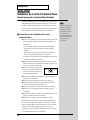
Installing the Wave Expansion Board
Up to two Wave Expansion Boards (SR-JV80 series; sold separately) can be
installed in EXP-D and E Slots in the XP-30. Wave Expansion Boards contain
Wave data, as well as Patches and Rhythm Sets that use this Wave data,
which can be called directly into the temporary area and played.
■ Cautions When Installing an Wave Expansion Board
● To avoid the risk of damage to internal components that can be caused by
static electricity, please carefully observe the following whenever you
handle the board.
• Before you touch the board, always first grasp a metal object (such as
a water pipe), so you are sure that any static electricity you might
have been carrying has been discharged.
• When handling the board, grasp it only by its edges. Avoid touching
any of the electronic components or connectors.
• Save the bag in which the board was originally shipped, and put the
board back into it whenever you need to store or transport it.
● Use a Philips screwdriver that is suitable for the size of the screw (a
number 2 screwdriver). If an unsuitable screwdriver is used, the head of
the screw may be stripped.
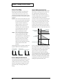
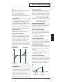
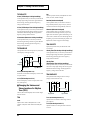
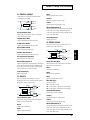
● To remove a screw, rotate the screwdriver
counter-clockwise. To tighten a screw, rotate
loosen
tighten
the screwdriver clockwise.
● When installing Wave Expansion Boards,
remove only the specified screws.
● Be careful that the screws you remove do not drop into the interior of the
XP-30.
● Do not leave the bottom cover in a detached state. Be sure to reattach it
after the Wave Expansion Boards have been installed.
● Do not touch any of the printed circuit pathways or connection terminals.
● Be careful not to cut your hand on the edge of the installation bay.
● Never use excessive force when installing a circuit board. If it doesn’t fit
properly on the first attempt, remove the board and try again.
● When circuit board installation is complete, double-check your work.
To install an optional Wave Expansion Board (SR-JV80 series; sold
separately), the unit’s bottom cover must be removed. There are two slots
(EXP-D and E) into which a board can be installed. Slots EXP-D and E
correspond to the group (XP-D and E) you need to select in order to use a
Wave, Patch or Rhythm Set from the Wave Expansion Board.
16
When playing a Patch or
Rhythm Set that use the
Wave data from a Wave
Expansion Board, the
appropriate Wave
Expansion Board must be
installed in the XP-30 for
the sound to play correctly.
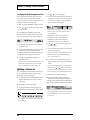
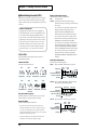
1
2
Before installing the Wave Expansion Board, turn off the
power of the XP-30 and all connected devices, and disconnect
all cables from the XP-30.
Turn the XP-30 on its back, and remove only the screws shown
in the following diagram.
fig.Q-02a.e
Screws to be removed
If the same type of Wave
Expansion Board is
installed in the EXP-D slot
and the EXP-E slot, it will
only be possible to select
data from the Wave
Expansion Board that was
installed in the EXP-D slot.
Also, the XP-30 already
contains the data of the
following three Wave
Expansion Boards, so if one
of these Wave Expansion
Boards is installed, only the
internal data (XP-A–C) can
be selected.
SR-JV80-09 “Session”
(XP-A)
SR-JV80-02 “Orchestral”
(XP-B)
SR-JV80-11 “Techno
Collection” (XP-C)
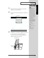
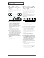
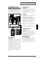
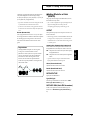
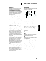
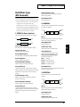
3
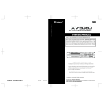
Inside, there are two connectors and six board holders. Insert
the connectors of the Wave Expansion Board into the internal
connectors, and simultaneously insert the board holders into
the holes of the Wave Expansion Board.
fig.Q-02b.e
Wave Expansion Board
EXP E
Board holder
Connector
EXP D
17
Quick Start
Getting Ready
Getting Ready
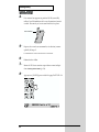
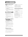
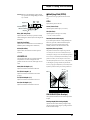
4
Use the Installation Tool supplied with the Wave Expansion
Board to turn the holders in the LOCK direction, so the board
will be fastened in place.
fig.Q-02c.e
Installation tool
5
LOCK
Use the screws that you removed in step 2 to fasten the cover
back in place.
This completes installation of the Wave Expansion Board.
6
7
8
fig.Q-03
18
Connect the cables that you disconnected earlier.
Turn on the power, as described in “Turning On the Power” (p.
26).
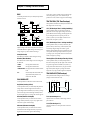
Press [PATCH] to access the PATCH PLAY display.
9
Quick Start
Getting Ready
Press [EXP D] or [EXP E], and verify that you can select
patches from Wave Expansion Boards D or E. [EXP D] or [EXP
E] indicator will light, and the following display will appear.
fig.Q-04
The example here depicts
what you would see if the
SR-JV80-13 “Vocal
Collection” Wave
Expansion Board were
installed in the EXP-D slot.
If you can’t choose any
Wave Expansion Board
patches, it’s possible that
the installed Wave
Expansion Board is not
being recognized correctly.
Turn off the power as
described in “Turning Off
the Power” (p. 26), and
re-install the Wave
Expansion Board correctly.
19
Getting Ready
Installation de la carte d’extension Wave
(French language for Canadian Safety Standard)
Vous pouvez installer jusqu’à 2 cartes d’extension Wave (en option dans la
série SR-JV80) dans les créneaux EXP-D et E du XP-30. Les cartes d’extension Wave contiennent des données Wave, aussi bien que des morceaux
musicaux et des ensembles rythmiques utilisant ces données, auxquelles on
peut directement accéder dans la zone temporaire et les faire jouer.
■ Precautions lors de l’installation de la carte
d’extension Wave
● Pour éviter tout dommage des composants internes pouvant provenir de
l’électricité statique, veuillez suivre les conseils suivants quand vous
installez la carte.
• Avant de toucher la carte, saisissez toujours un objet métallique
(tuyau d’eau ou autre) pour être sûr que l’électricité statique se
décharge.
• Quand vous saisissez la carte, prenez-la par les bords. Evitez de
toucher les composants électroniques ou les connecteurs.
• Conservez le sac dans lequel la carte était emballée et remettez la carte
dedans pour l’expédier ou l’entreposer.
● Utiliser un tournevis cruciforme correspondant à la taille de la vis (un
tournevis numéro 2). En cas d’utilisation d’un tournevis inapproprié, la
tête de la vis pourrait être endommagée.
● Pour enlever les vis, tourner le tournevis
dans le sens contraire des aiguilles d’une
desserrer
resserrer
montre. Pour resserrer, tourner dans le
sens des aiguilles d’une montre.
● Lors de l’insertion de la carte d’extension Wave, enlevez seulement les vis
indiquées dans les instructions.
● Veillez à ne pas laisser tomber de vis dans le châssis du XP-30.
● Ne pas laisser le panneau de protection avant détaché. S’assurer de
l’avoir rattacher après avoir installé le disque dur.
● Ne touchez aucun des circuits imprimés ni les bornes de connexion.
● Veillez à ne pas vous couper les doitgs sur le bord de l’ouverture
d’installation.
● Ne jamais forcer quand vous installez une carte de circuits. Si la carte ne
rentre pas correctement, ressortez-la et ressayez.
● Quand la carte est installée, vérifiez si l’installation est correcte.
Pour installer une carte d’extension Wave optionnelle (série SR-JV80), le
panneau du bas de l’appareil doit être enlevé. Vous trouverez 2 créneaux
(EXP-D et E) dans lesquels vous pourrez installer une carte. Les créneaux
EXP-D et E correspondent au groupe (XP-D et E) que vous devez
sélectionner pour pouvoir utiliser une donnée Wave, un morceau musical
ou un ensemble rythmique de la carte d’extension.
20
Quand vous faites jouer un
morceau ou un ensemble
rythmique qui utilise des
données Wave de la carte
d’extension, une carte
d’extension appropriée doit
être installée dans le XP-30
afin que le son sorte
correctement.
1
2
Éteindre le XP-30 et tous les appareils qui y sont reliés et
débrancher tous les câbles du XP-30.
Retournez le XP-30 et enlevez seulement les vis indiquées sur
la figure.
fig.Q-02a.f
Vis à enlever
Si la même sorte de carte
d’extension Wave est
installée dans les créneaux
EXP-D et EXP-E, il ne sera
possible de sélectionner
que les données de la carte
d’extension Wave installée
dans le créneau EXP-D. De
plus, le XP-30 contient déjà
les données des 3 cartes
d’extension Wave
suivantes si bien que si une
de ces 3 cartes est installée,
seules les données internes
(XP-A–C) pourront être
sélectionnées.
SR-JV80-09 “Session”
(XP-A)
SR-JV80-02 “Orchestral”
(XP-B)
SR-JV80-11 “Techno
Collection” (XP-C)
3
À l’intérieur, il y a 2 connecteurs et 6 supports à carte. Insérer
les connecteurs de la carte d’extension Wave dans les
connecteurs internes tout en insérant simultanément les
supports à carte dans les trous de celle-ci.
fig.Q-02b.f
Carte d'extension Wave
EXP E
Support à carte
Connecteur
EXP D
21
Quick Start
Getting Ready
Getting Ready
4
Pour tourner les supports en position LOCK (verrouillé),
utilisez l’outil d’installation de la carte d’extension fournie à
cet effet. De cette façon, la carte sera bien fixée à sa place.
fig.Q-02c.f
Outil d'installation
5
LOCK
Reposez le couvercle en remettant les vis enlevées (comme
spécifié) à l’étape 2.
L’installation de la carte d’extension Wave est terminée.
6
7
8
fig.Q-03
22
Rabranchez les câbles.
Mettez le XP-30 sous tension en procédant comme indiqué
dans “Turning On the Power” (p. 26).
Appuyer sur [PATCH] pour accéder à la page PATCH PLAY.
9
Quick Start
Getting Ready
Appuyer sur [EXP D] ou [EXP E] et vérifier si vous pouvez
sélectionner les morceaux musicaux des cartes d’extension
Wave D ou E. L’indicateur [EXP D] ou [EXP E] s’allumera et
l’affichage suivant apparaîtra.
fig.Q-04
Ceci est un exemple
d’affichage lorsque la carte
d’extension Wave SR-JV8013 “Vocal Collection” est
installée dans le créneau
EXP-D.
Si vous ne pouvez choisir
aucun des morceaux
musicaux de la carte
d’extension Wave, il est
possible que la carte
installée ne soit pas
reconnue correctement.
Éteignez l’appareil comme
indiqué dans “Turning
Off the Power” (p. 26) et
réinstaller la carte
correctement.
23
Getting Ready
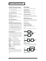
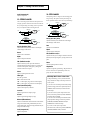
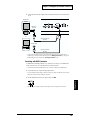
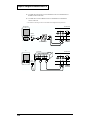
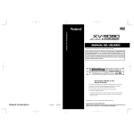
Making Connections
The XP-30 does not contain an amp or speakers. In order to hear sound, you
will need to connect it to a keyboard amp, audio system, or headphones.
Refer to the following diagram and connect the XP-30 to the external
equipment you are using.
fig.Q-05.e
to Power outlet
External MIDI device
Stereo headphones
Roland
Pedal switch
Expression pedal (EV-5) or pedal switch
Stereo set, etc.
1
24
Before you make connections, make sure that power is turned
off for all devices.
Speaker with built-in amp,
keyboard amp, etc.
To prevent malfunction
and/or damage to speakers
or other devices, always
turn down the volume, and
turn off the power on all
devices before making any
connections.
2
3
Connect supplied AC power cable to the XP-30, and plug the
other end into an AC power outlet.
Connect audio cables and MIDI cables as shown in the
diagram. If you are using headphones, plug them into the
PHONES jack. Connect pedal switches or expression pedals as
necessary.
Quick Start
Getting Ready
On 117V models the AC
cable is permanently
attached to the unit.
In order to take full
advantage of the XP-30’s
performance, we
recommend using a stereo
amp/speaker system, If
you are using a mono
system, make you
connections to the
OUTPUT jack L (MONO).
CONTROL PEDAL jack
can also accommodate
pedal switches.
Use only the specified
expression pedal (EV-5;
sold separately). By
connecting any other
expression pedals, you risk
causing malfunction and/
or damage to the unit.
For information on making
the connection with the
computer, take a look at
“Connecting to Your
Computer” (p. 134).
25
Getting Ready
Turning On the Power
1
Before you turn the power on, check to make sure that:
• All external devices are correctly connected to the XP-30.
• The volume controls of the XP-30 and the amp/mixer system are turned
down all the way.
2
Turn on the power switch located on the rear panel of the XP30.
Once the connections have
been completed (p. 24),
turn on power to your
various devices in the order
specified. By turning on
devices in the wrong order,
you risk causing
malfunction and/or
damage to speakers and
other devices.
fig.Q-06
3
4
Turn the power on of your amp or audio system.
This unit is equipped with
a protection circuit. A brief
interval (a few seconds)
after power up is required
before the unit will operate
normally.
Play the XP-30 and gradually raise the volume controls of the
XP-30, your amp or mixer to an appropriate volume level.
fig.Q-07
Be careful not to raise the
VOLUME slider of the XP30 too much. Excessive
volume may damage your
amp/speaker system or
could cause hearing
■ Turning Off the Power
1
Before you turn power off, check to make sure that:
• The volume controls of the XP-30 and the amp/mixer system are turned
down all the way.
• Important data has been saved to a memory card (p. 122).
2
Turn off your amp/mixer system.
3
Turn off the XP-30 power.
26
Getting Ready
Quick Start
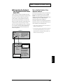
Reset to Default Factory Settings
(Factory Reset)
Before using XP-30 for the first time, reset it to its default factory settings
using Factory Reset. Different settings may result in unexpected effects.
fig.Q-08
1
1
2
Press [UTIL/CARD] to make the indicator blink.
The UTIL 1 display will appear.
fig.Q-09
2
3 4
Press [ ].
The UTIL 2 display will appear.
Factory Reset operation
resets all data in the
internal memory and user
memory to factory presets.
Save any important data to
a memory card before
executing this operation (p.
122).
fig.Q-09a
3
Press the numeric key [4].
The FACTORY RESET display will appear.
fig.Q-10
4
Press [ENTER].
If “Internal Write Protect= ON” message is displayed, press [DEC] to turn
the setting OFF. After pressing [ENTER] to clear the message, press
[ENTER] again to reset to the factory preset settings.
For more information
about the Internal Write
Protect, please refer to
“Preventing User
Memory Writing
Operation (PROTECT)”
(p. 121).
27
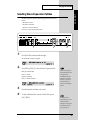
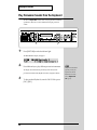
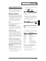
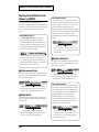
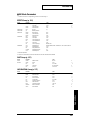
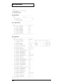
Listening to the Demo Song
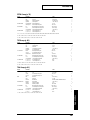
The XP-30 contains 9 demo songs and you use Demo Play to play it. It’s the
easiest introduction to the XP-30’s exceptional sounds and effects.
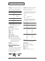
Demo Song
Composer/Copyright
TRANSFERENCE
CHANTERELLE
VECTORIAL
All In Good Time
TEKKNO MILLENNIUM
A Shadow’s March
Guitars Forever
Rude99
Overtime
Scott Tibbs © 1999 Roland Corporation
Scott Tibbs © 1999 Roland Corporation
Scott Tibbs © 1999 Roland Corporation
Scott Wilkie © 1999 Scott Wilkie Media (ASCAP)
MASA © 1999 COPYRIGHT CONTROL
Steve Lu © 1999 Stephen Lu
Gundy Keller © 1999 Gundy Keller / A-TOWN recordings
Hans-Joerg Scheffler © 1999 Hans Scheffler
Hans-Joerg Scheffler © 1999 Hans Scheffler
All rights reserved.
Unauthorized use of this
material for purposes other
than private, personal
enjoyment is a violation of
applicable laws.
fig.Q-11
4
1
2
1
3
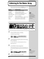
Hold down [SHIFT] and press [CATEGORY].
The DEMO PLAY display will appear.
fig.Q-12
2
Turn the VALUE dial or press [INC]/[DEC] to select the song
that you wish to hear.
If you select “CHAIN-PLAY,” the songs will playback successively,
beginning from the first.
3
Press [ENTER] to start demo song playback.
When a demo song plays all the way to the end, it automatically returns to
the start of the song, and playback is repeated. To interrupt playback, press
[EXIT].
fig.Q-13
4
28
No data for the music that
is played will be output
from MIDI OUT.
To return to the previous display, press [EXIT].
■ Profile of the Composer
Scott Tibbs
Scott Tibbs has performed and conducted for several orchestral groups, including the Atlanta Symphony
Orchestra, throughout the United States, Canada, Latin America, and Japan. His diverse compositional output
ranges from numerous film, theater and television projects to the symphonic concert stage. For the past four years,
he has been teaching music composition and theory at UCLA where he has received a Ph.D. degree in composition.
He has performed with well-known artists Dizzy Gillespie, Bill Cosby, Jerry Sienfeld, and Bobby Shew, amongst
numerous others.
Gundy Keller
Gundy Keller, a Germany-based guitarist, songwriter and producer, has been an international demonstrator for
Roland since 1986. Gundy focuses mainly on the GR synthesizers and the V-Guitar, for international music
conventions as well as recording sessions requesting completely unusual guitar sounds. Besides creating his own
production company, he’s the founder and director of Rocksound Music School, a private institute for music
instruction. Check out some of his other work on the Roland VG-8 Demo CD, or the Roland GR-30 Video.
Steve Lu
Steve Lu is a recent graduate of Berklee College of Music, majoring in Music Production & Engineering. His recent
musical efforts include a soundtrack album, featuring synthesized re-creations of movie themes such as “Titanic”
and “The Rock,” as well as production and arrangements for saxophonist Jimmy Reid’s self-titled album. He is
currently working with artists Brandy and Ray-J on future projects.
Scott Wilkie
Scott Wilkie is a contemporary jazz recording artist, based in southern California. He tours frequently with his own
band, and also appears as an artist for Roland in the U.S., Japan, Europe and South America. His debut solo album,
Boundless, was released worldwide in 1999 on Narada/Virgin Records. You can find him on-line at
www.scottwilkie.com.
Hans-Joerg Scheffler
Born and raised in the Ruhr valley, the biggest industrial area in Germany, Hans’s attraction to noise and rhythm
came naturally.
Today he runs his own company, DIGITAL AUDIO DESIGN, which produces sampling CDs and CD ROMs.
He works for Roland as a pro audio product specialist, as a sound designer for expansion boards, and as a
composer of demo songs. He has released several CDs that use the Roland RSS system.
Soundclips of his work can be downloaded at: http://www.united-sound.com/usmaster/cell2downde.htm
MASA
Masa has performed live, mainly at psychedelic-trance parties since the early 90’s.
In the spring of 1996, he released the album “Just Inside” from East-West. Interest in his work is increasing, and
new releases are appearing under a variety of labels, including Tokyo Tekno Tribe Records and Psy-Harmonics.
Web site: www.ifnet.or.jp/~masa-k/
29
Quick Start
Listening to the Demo Song
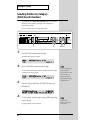
Playing the Sounds
Selecting Patches and Playing the Sounds
The XP-30 contains a large number of sounds ready for you to play. The
sounds that you select and play on the XP-30 are generally called Patches.
Here’s how to select and play Patches.
fig.Q-14
1
1
3
4
Press [PATCH] to make the indicator light.
The PATCH PLAY display will appear.
fig.Q-15
2
3
4
Play the keyboard and listen to the sound.
To select a different Patch, turn the VALUE dial or press
[INC]/[DEC].
To change the Patch Group, hold down [SHIFT] and press any
key from [1] through [6] on the numeric keypad.
[SHIFT] + [1]: PR-A (Preset A)
[SHIFT] + [2]: PR-B (Preset B)
[SHIFT] + [3]: PR-C (Preset C)
[SHIFT] + [4]: PR-D (GM (General MIDI))
[SHIFT] + [5]: PR-E (Preset E)
[SHIFT] + [6]: USER (User)
30
By using the Phrase
Preview function, you can
audition patches by
listening to a preset phrase
suitable for the selected
type of patch (p. 33).
Playing the Sounds
Quick Start
Selecting Wave Expansion Patches
The XP-30 contains the patches of the following popular Wave Expansion
Boards:
• SR-JV80-09 “Session”
• SR-JV80-02 “Orchestral”
• SR-JV80-11 “Techno Collection”
Here’s how to select and play these patches.
fig.Q-16
1
1
4
2
Press [PATCH] to make the indicator light.
The PATCH PLAY display will appear.
fig.Q-15
2
Press [EXP A]–[EXP C] to select the Wave Expansion Patch
that you wish to hear.
[EXP A]: “Session”
[EXP B]: “Orchestral”
[EXP C]: “Techno Collection”
fig.Q-17
3
4
When a Wave Expansion
Board of the SR-JV80 series
(sold separately) is
installed in the EXP-D or
EXP-E Wave Expansion
Board slot, you can press
[EXP D] or [EXP E] to
choose the corresponding
patches.
Play the keyboard and listen to the sound.
To select a different Patch, turn the VALUE dial or press
[INC]/[DEC].
By using the Phrase
Preview function, you can
audition patches by
listening to a preset phrase
suitable for the selected
type of patch (p. 33).
31
Playing the Sounds
Selecting Patches by Category
(Patch Search Function)
The JV-2080 provides a Patch Search Function that allows you to quickly
find Patches of the specified type (Category). The 38 categories are
organized into 10 groups.
Here’s an example of how to find organ-type Patches.
fig.Q-18
1
1
5
2,6 3 4
Press [PATCH] to make the indicator light.
The PATCH PLAY display will appear.
fig.Q-15
2
Press [CATEGORY] to make the indicator light.
The Patch Search function will be turned on, and the patch number display
will change to the category display.
fig.Q-19
3
Now you can select patches
within the specified
category, either by rotating
the VALUE dial, or by
using [INC] or [DEC]. To
change the category group,
use the numeric keys.
Select the category. Hold down [CATEGORY] and press [2
(KEY&ORG)].
fig.Q-20
4
For this example, select the Organ category (ORG) by pressing
numeric key [4].
Organ-type patches can now be selected.
32
For details on the
categories you can select,
refer to page 49.
5
Turn the VALUE dial or press [INC]/[DEC] to select a patch.
6
Press [CATEGORY] to make the indicator go dark.
The Patch Search function will be turned off, and the normal PATCH PLAY
display will reappear.
By using the Phrase
Preview function, you can
audition patches by
listening to a preset phrase
suitable for the selected
type of patch (p. 33).
Auditioning the Patches (Phrase Preview)
The XP-30 allows you to preview Patches by hearing a phrase appropriate
for each type of Patch.
fig.Q-21
1 2,3
1
Press [PATCH] to make the indicator light.
The PATCH PLAY display will appear.
fig.Q-15
2
Press and hold [PHRASE PREVIEW].
If the factory settings have just been restored, the USER: 001 Temple of XP
Patch will sound.
3
Release your finger from [PHRASE PREVIEW], and the phrase
will stop playing.
You can change the phrase
that is played by the Phrase
Preview, and modify the
way in which the phrase is
played. For details, refer to
“Using Phrase Preview
to Play Patches” (p. 49),
and “Phrase Preview
Settings (PREVIEW)”
(p. 113).
33
Quick Start
Playing the Sounds
Playing the Sounds
Try Out Performance Functions
The XP-30 provides various controllers that can modify the sound. While
playing patches, try out these controllers and listen to effects they can
produce.
■ Velocity/Aftertouch
The force with which you play the keyboard (velocity) can affect the volume
or timbre of the sound. Aftertouch (pressure you apply to a key after playing
a note) can also affect the sound.
The effect that the
controllers have will
depend on the settings of
the selected Patch. If the
effects of the controllers are
difficult to detect, select
another Patch.
■ Pitch Bend/Modulation Lever
While playing the keyboard, move the lever to the left to lower the pitch, or
to the right to raise the pitch. This is known as Pitch Bend. You can also
apply vibrato by manipulating the lever away from you. This is known as
Modulation.
If you move the lever away from you and at the same time move it to the
right or left, you can apply both effects simultaneously.
fig.Q-22.e
Modulation
Pitch Bend
■ C1–C4 Slider
By moving the sliders up and down while fingering the keyboard, you can
control the various functions assigned to the sliders.
To control them, press [CONTROLLER] to make the indicators light up,
then move the sliders.
Additionally, if you hold down [CONTROLLER] while moving one of the
C1–C4 sliders, you can go to the ASSIGN display for that slider. There you
can check and make settings for the function that is to be controlled with the
slider. Make changes in the settings while holding down [CONTROLLER].
fig.Q-23
At the factory default
settings, you can use the C1
through C4 sliders to
control the functions
described below.
C1: AFTERTAUCH
C2: BREATH
C3: PORTA-TIME
(Portamento time)
C4: MODULATION
How sound varies depends
on the current setting. For
details, refer to “C1/C2/
C3/C4 ASSIGN (C1/C2/
C3/C4 Slider Assign)”
(p. 111).
34
Playing the Sounds
Quick Start
■ Hold Pedal
If an optional pedal switch is connected to the rear panel HOLD PEDAL
jack, pressing the pedal switch will sustain (hold) the sound even if the keys
are released.
■ Expression Pedal
If an optional expression pedal is connected to any of the rear panel
CONTROL PEDAL jack, you can use the pedal to control the volume or
timbre of sound.
How sound varies depends
on the current setting. For
details, refer to “CONTROL
PEDAL” (p. 110).
■ Solo
You can play using single notes, by pressing [SOLO] (indicator lights). This
function is especially effective when playing a sax, flute or other
monophonic instrument.
Using [PORTAMENTO] with [SOLO] ON allows you to simulate
performance techniques like violin glissandos.
fig.Q-24
For details, refer to
“Playing Single Notes
(Solo)” (p. 50).
■ Portamento
As you play the keyboard, you can make pitch slide smoothly from one key
to another, by pressing [PORTAMENTO] (indicator lights).
fig.Q-25
For details, refer to
“Creating Smooth
Pitch Changes
(Portamento)” (p. 50).
35
Playing the Sounds
■ Sound Palette
While playing the keyboard, you can move the sliders up or down to modify
volume level or sound character.
To change sound character, press [FILTER/ENV] to light the indicator and
move the sliders.
To change the volume level, press [LEVEL] to light the indicator and move
the sliders.
fig.Q-26
For details, refer to “Using
the Sliders to Modify
the Sound in Realtime
(Sound Palette
Function)” (p. 50, 54).
Play Arpeggios (Arpeggiator)
You can play a broken chord (arpeggio) automatically, by simply pressing a
chord. For example, if you press a C major chord, the XP-30 plays an
arpeggio such as C → E → G → C → E → G...
fig.Q-27
6
1
2,4,5,7
1
Press [PATCH] to make the indicator light.
The PATCH PLAY display will appear.
fig.Q-15
2
36
Press [ARPEGGIO] to make the indicator light.
5
3
Quick Start
Playing the Sounds
Play a chord.
XP-30 will play an arpeggio, according to the notes forming the chord you
have just voiced.
4
Continue holding down [ARPEGGIO], and the ARP SELECT
display will appear.
fig.Q-28
In this page you can change the Style, Accent Rate, Octave Range and
Tempo of the arpeggio. Here’s how to change the Style.
5
Hold down [ARPEGGIO], and press [ ] or [ ] to move the
cursor (underline) to the Style parameter. Then rotate the
VALUE dial to select various settings.
For details regarding
playing arpeggios, refer to
“Playing an Arpeggio”
(p. 56) and “Arpeggio
Depending on the value you enter, the way arpeggios play will vary.
Settings (ARPEGGIO)”
(p. 108).
6
Hold down [ARPEGGIO] and press [TRANSPOSE]. The
[ARPEGGIO] indicator will begin blinking, and the arpeggio
will continue sounding even after you take your hand off the
keyboard (Hold).
To stop the arpeggio from being sounded by the Hold function, hold down
[ARPEGGIO] again and press [TRANSPOSE]. The indicator changes from
blinking to lit.
7
To finish playing arpeggios, press [ARPEGGIO] again so the
indicator turns off.
37
Playing the Sounds
Play Percussion Sounds from the Keyboard
The XP-30’s Rhythm Sets contain a wide variety of percussion sounds and
special effects. Here’s how to select a Rhythm Set and play percussion
sounds.
fig.Q-29
1
1
3
Press [RHYTHM] to make the indicator light.
The RHYTHM PLAY display will appear.
fig.Q-30
2
Press different keys to play different percussion instruments.
The display will indicate the last-pressed key (Note name) and the
percussion instrument name (Rhythm Tone name) assigned to that key.
3
38
To select another Rhythm Set, turn the VALUE dial or press
[INC]/[DEC].
The percussion instrument
played by each key will
depend on the selected
Rhythm Set. For details,
refer to “Rhythm Set
List” (p. 177).
Chapter 6 Chapter 5 Chapter 4 Chapter 3 Chapter 2 Chapter 1
Advanced Use
39
Chapter 1. Overview of the XP-30
XP-30 Configuration
■ Classification of XP-30 Sound
Types
■ Basic Configuration
XP-30 sounds are made up of the following types:
The XP-30 consists of a sound source and controllers.
fig.1-01.e
Sound source
section
Play
Tones
In the XP-30, the Tone is the smallest class of sound. Each
Tone consists of one sound. But when you play the XP-30
you will mostly play a Patch, which is made up of several
Tones. Tones therefore are the elements which collectively
form a Patch.
Tone configuration:
fig.1-02.e
Tone
LFO 1
LFO 2
Controller section (controllers such as
keyboard, pitch bend lever, etc.)
Sound Source
The XP-30 sound source produces sound by responding to
commands in the form of MIDI messages received from its
controllers. It will also produce sound by responding to
commands received from various external devices it can be
connected to.
WG
TVF
TVA
Pitch
Envelope
TVF
Envelope
TVA
Envelope
audio signal
Controllers
Controllers include the keyboard, front panel sliders and
pedals which are connected to their respective rear panel
jacks. Adjusting these controllers enable you to produce or
modify sound.
control signal
WG (Wave Generator)
Using the Wave Generator, you select a waveform and set its
pitch.
TVF (Time Variant Filter)
With the Time Variant Filter, you modify the waveform’s
frequency characteristics.
TVA (Time Variant Amplifier)
With the Time Variant Amplifier, you set volume level and
set the sound’s position in a stereo soundfield.
Envelope
You use Envelope to initiate changes to occur to a sound over
time. There are separate Envelopes for the WG (pitch), TVF
(filter) and TVA (volume). For example, to modify a sound’s
attack and decay time, you would use TVA Envelope to
adjust volume changes to the sound over time.
LFO (Low Frequency Oscillator)
Use the LFO to create cyclic changes (modulation) in a
sound. The XP-30 has two LFOs. Either one or both can be
applied to effect the WG (pitch), TVF (filter) and/or TVA
(volume). To illustrate this control’s action, you can apply an
LFO to modify the WG (pitch) to create vibrato. If the LFO is
used to modify the TVA (volume), you’ll get tremolo.
40
Patches
Rhythm Sets
Patches are the basic sound configurations that you play
during a performance. Each Patch can be configured by
combining up to four Tones. How the four Tones are
combined is determined on the STRUCT display (PATCH/
COMMON).
A Rhythm Set is a grouping of percussion instruments
(Rhythm Tones). Since percussion instruments generally do
not play melodies, there is no need for a percussion
instrument sound to be able to play a scale on the keyboard.
It is however, more important that as many as possible
percussion instruments be available to you at the same time.
Therefore, each key (Note number) of a Rhythm Set will
produce a different percussion instrument.
fig.1-03.e
Patch
fig.1-05.e
Rhythm Set
Tone 4
Tone 3
Tone 2
Tone 1
Note Number 98 (D7)
Note Number 97 (C#7)
LFO 1
LFO 2
Note Number 36 (C2)
Note Number 35 (B1)
Rhythm Tone (Percussion instrument sound)
WG
Pitch
Envelope
WG
TVF
TVA
Pitch
Envelope
TVF
Envelope
TVA
Envelope
TVA
TVF
TVF
Envelope
TVA
Envelope
Parts
Performances
The next level in sound configuration. A single Performance
groups 15 Patches and one Rhythm Set so that they can be
combined to play ensembles or produce fabulously rich,
thick sounds. One Performance allows a single XP-30 to
control up to 16 instrument sounds. Because the XP-30 sound
source can control multiple sounds (instruments) it is called a
“multitimbral sound source.”
fig.1-04.e
Performance
For details regarding following items, please refer to each
corresponding page.
About the Memory (p. 67)
About the Effects (p. 61)
Part 16 (MIDI receive ch.)
Part 11 (MIDI receive ch.)
Patch
Keyboard,
MIDI
When the XP-30 is used as a multitimbral sound source,
another sound configuration called a Part comes into play. A
Part contains a Patch or Rhythm Set. For multitimbral
applications, the Performance consists of 16 Parts. A specific
Patch can be assigned to each Part except Part 10 because
Part 10 is universally set as the Drum Part to which a Rhythm
Set (discussed above) is assigned. In a multitimbral context, it
helps to think of a Performance as an orchestra, each Part in
it being a musician, and the Patch or Rhythm Set that
musician’s instrument.
Part 10 (MIDI receive ch.)
Rhythm Set
Sound
Part 9 (MIDI receive ch.)
Part 1 (MIDI receive ch.)
Patch
41
Chapter 1
Chapter 1. Overview of the XP-30
Chapter 1. Overview of the XP-30
■ Number of Simultaneous Voices
The XP-30 is able to produce up to 64 voices simultaneously.
The following paragraphs discuss what this means, and what
will happen when more than 64 simultaneous voices are
requested from the XP-30.
Calculating the Number of Voices
Being Used
The XP-30 is able to produce up to 64 simultaneous voices.
However this number is not simply the number of notes
being played, but depends on the number of Tones used in
each Patch. If you are playing one Patch which uses 4 Tones,
you will be able to play 16 simultaneous notes. If you are
using the XP-30 in Performance mode to play an ensemble,
count the total number of Tones used by all the Parts using
the following formula.
Basic Operation
■ Switching Modes
The XP-30 contains a large number of functions. In order to
organize these functions for easy access, they are grouped
into the following modes. The mode that is selected will
affect the way in which the sound source operates, how data
is shown in the display, and how the function buttons work.
Use the Mode buttons to select the mode. The indicator of the
selected button will light/blink, and the display will change
according to the selected mode.
fig.1-06
(currently sounding notes) x (number of Tones used in the
Patch being played)
How a Patch Uses Notes
When the XP-30 is requested to play more than 64 voices
simultaneously, a currently-sounding note will be turned off
to make room for the newly requested note. The note with
the lowest priority will be turned off first. The order of
priority is determined by the Voice Priority setting.
Voice Priority can be set either to Last or Loudest. When Last
is selected, a newly requested note that exceeds the 64 voice
limit will cause the first-played of the currently sounding
notes to be turned off. When Loudest is selected, the quietest
of the currently sounding notes will be turned off.
Normally you will set Voice Priority to Last.
Note Priority in Performance Mode
Since Performance mode is usually used to play an ensemble
consisting of several Patches, it is important to decide which Parts
take priority. Priority is specified by the Voice Reserve settings.
When a note within a Patch needs to be turned off to make room
for a new note, the Voice Priority setting of the Patch will apply.
Sound Source
Selecting Patch mode, Performance mode, Rhythm Set mode,
and GM mode will determine sound source operation. One
mode always has to be selected.
Patch Mode
In this mode, you can play an individual Patch from the
keyboard or modify Patch settings. If you’re using an
external MIDI device to control the XP-30 in this mode, it will
function as a single-patch sound source.
Performance Mode
This mode makes the XP-30 function as a multitimbral sound
source, and Performance settings can be modified. If you’re
using an external MIDI device to control the XP-30 in this
mode, it will function as a multitimbral sound source.
To modify the settings of a Patch that’s assigned to a Part,
hold down [PERFORM] and press [PATCH]. Both button
indicators will light.
Voice Reserve
Rhythm Set Mode
The XP-30 has a Voice Reserve function that lets you reserve
a minimum number of notes that will always be available for
each Part. For example if Voice Reserve is set to 10 for Part
16, Part 16 will always have 10 notes of sound-producing
capacity available to it even if a total of more than 64 notes
(total for all Parts) are being requested. When you make
Voice Reserve settings, you need to take into account the
number of notes you want to play on each Part as well as the
number of Tones used by the selected Patch.
This is how you can play a Rhythm Set from the keyboard
and modify the Rhythm Set settings. In this mode, the
keyboard will play the Rhythm Set, but the XP-30 continues
to function as a multitimbral sound source. So your effects
settings of the currently selected Performance will be heard
as you play the Rhythm Set. Rhythm Sets are assigned to Part
10 of the Performance. If you’re using an external MIDI
device to control the XP-30 in this mode, it will still function
as a multitimbral sound source.
* It is not possible to make Voice Reserve settings that would
cause the total of all Parts to be greater than 64 voices.
42
Chapter 1. Overview of the XP-30
GM Mode
■ About the Function Buttons
This special mode makes the XP-30 function as a GM
compatible sound source. You should select this mode when
you want to play back a GM score (music files created for
GM sound source).
To set GM mode, hold down [SHIFT] and press [PERFORM].
[PERFORM], [PATCH] and [RHYTHM] indicators will not
light.
Function buttons are buttons that perform a variety of
functions. The function they perform will depend on the
current mode, and on whether [EDIT] is on (lit) or off (dark).
[EDIT] will turn on or off each time you press it.
This mode is for determining global XP-30 settings such as
tuning, display contrast and how MIDI messages are
received.
* Some System mode parameters relate to an entire Patch or an
entire Performance. To set these parameters, press [SYSTEM]
in the selected mode (Patch or Performance).
Utility/Card Mode
Here you can save and transmit settings for the sound
generator, and make settings related to memory cards.
* Some Utility/Card mode parameters relate to an entire Patch,
Performance or Rhythm Set. To set these parameters, press
[UTIL/CARD] in the selected mode (Patch, Performance or
Rhythm Set).
* [EDIT] switches the function of the function buttons, but
pressing [EDIT] will not make the display change. If you wish
to modify a setting, press the [EDIT] to make the indicator light,
and then press a function button to select the display group and
switch the display. When you finish making settings, press
[EXIT] or a mode button to switch the display.
In Performance Mode
([EDIT] Indicator is Dark)
fig.1-08
The function buttons will act as Part buttons ([PART]) that
switch Parts on (lit) or off (dark). Since 16 Parts are being
controlled using only 8 buttons, use [1-8/9-16] to select
which set of Parts you are controlling. When [1-8/9-16]
indicator is dark, you can switch Parts 1–8 on/off. When it is
lit, you can switch Parts 9–16 on/off.
If the [EDIT] indicator is turned off in the Part setting
display, the function buttons will act as PART buttons that
select the Part to be edited.
* The function of the Part on/off setting will depend on the setting
of the Key Mode parameter (PERFORM/COMMON/
PERFORM COMMON) (p. 83).
43
Chapter 1
System Mode
fig.1-07
Chapter 1. Overview of the XP-30
In Patch Mode ([EDIT] Indicator is Dark)
■ About the Cursor Buttons
fig.1-09
The cursor buttons are used to move between display pages
or to move the cursor.
fig.1-12
The function buttons will act as Tone Switch buttons ([TONE
SWITCH]) and Tone Select buttons ([TONE SELECT]).
[TONE SWITCH] allow you to turn each Tone in the Patch
on (lit) or off (dark). When a Tone is turned on, it can be
heard.
Use [TONE SELECT] to select the Tone you wish to modify.
To select a Tone to modify, turn off [EDIT] indicator in the
Tone setting display. To select two or more Tones
simultaneously, hold down one of [TONE SELECT] and
press the other [TONE SELECT]. In this case, the numbers of
Tones other than the first-selected Tone will be displayed as *
symbols.
In Rhythm Set Mode
([EDIT] Indicator is Dark)
fig.1-10
The function buttons (TONE SELECT section) will select the
key shown in the display.
If the [EDIT] indicator is turned off in the Rhythm Set setting
display (the setting display for individual keys), the function
buttons will select the key to be edited.
[TONE SELECT 1]: move to an octave lower key
[TONE SELECT 2]: move to the semitone below
[TONE SELECT 3]: move to the semitone above
[TONE SELECT 4]: move to an octave higher key
When [EDIT] Indicator is Lit
Each mode contains a large number of settable items, and
these items are organized into groups. When [EDIT]
indicator is lit, the function buttons are used to select display
groups. The displays that appear will depend on the current
mode. The groups that can be selected in each mode are
printed on the front panel above the buttons.
fig.1-11
* For information on what the function buttons do in GM mode,
please see “Chapter 5. Using the XP-30 as the GM Sound
Module” (p. 124).
44
Moving Between Display Pages
The various displays are grouped by function button, and
each group contains several display pages. Use the cursor
buttons to move between these display pages and groups.
Moving Between Pages
An upward-pointing arrow ( ) shown in the display
indicates that one or more pages exist before this page. A
downward-pointing arrow ( ) shown in the display
indicates that one or more pages exist after this page. Press
[ ] to move to the previous page, or [ ] to move to the next
page. Pressing [ ] while holding [SHIFT] will jump to the
first page. Pressing [ ] while holding [SHIFT] will jump to
the last page.
fig.1-13
Moving Between Groups
From one of the Play displays, hold down [SHIFT] and press
[ ] to access the left-most function button group display.
In group displays that you select using the function buttons,
you can hold down [SHIFT] and press [ ] to move to the
group of the function button to the left, or hold down
[SHIFT] and press [ ] to move to the group of the function
button to the right.
Whenever you are in any group display, you can move to
another group even if [EDIT] indicator is dark. In other
words, this procedure allows you to move to a different
group without having to turn on [EDIT] indicator, and is a
faster and more efficient way to get around.
Chapter 1. Overview of the XP-30
Moving the Cursor (underline)
[0]–[9] (Numeric Keys)
When two or more items are shown in a single display page,
move the cursor (underline) to the item whose value you
wish to set. Press [ ] to move the cursor to the left, or [ ]
to move it to the right.
[0]–[9] (Numeric Keys) lets you directly specify a numerical
value. When you enter the number, the value will blink. This
indicates that the value has not yet been finalized. To finalize
the value press the ENTER button. To reverse the sign of the
number (+/-), hold down [SHIFT] and press [0].
A symbol appearing in the upper right of the display
indicates that there are other items in this page that the
screen has no room to show. Press [ ] to see these items,
and press [ ] to return to the previous display.
fig.1-15
* Some parameters do not require you to press [ENTER] to
finalize the value.
< Example 1: To enter a value of 38 >
Press [3] → press [8] → press [ENTER]
< Example 2: To enter a value of -60 >
While holding down [SHIFT] press [0] → press [6] → press
[0] → press [ENTER]
* You can switch from a positive to negative numerical value
anytime before you press [ENTER].
Special Functions of the Numeric Keys
■ Modifying a Value
To modify a value, use the VALUE dial, [INC]/[DEC] or [0]–
[9] (numeric keys).
fig.1-16
You can use the numeric keys to specify non-numerical
settings for some parameters.
* For the procedure of using the Numeric Keys to enter the
characters or symbols in a name, refer to “Assigning a
Name” (p. 46).
Performance/Patch/Rhythm Set Group
In the PLAY displays of Performance mode/Patch mode/
Rhythm Set mode, you can use the numeric keys to specify
groups. To specify the group, hold down [SHIFT] and press
numeric keys to specify groups.
* Each parameter has a specific range, so you cannot set any value
smaller than the minimum value or greater than the maximum
value.
VALUE Dial
Rotating the VALUE dial clockwise increases the value,
counterclockwise decreases the value. Holding down
[SHIFT] as you move the VALUE dial increases value
increments so you can make large value changes faster.
[INC] and [DEC]
Pressing [INC] increases the value, and [DEC] decreases it.
Keep [INC] or [DEC] pressed for continuous adjustment. For
faster value increases, keep [INC] pressed down and press
[DEC]. For decreasing value faster, keep [DEC] pressed
down and press [INC].
If you press [INC] or [DEC] while holding down [SHIFT], the
value increments will get bigger.
Buttons
[SHIFT]+[1]
[SHIFT]+[2]
[SHIFT]+[3]
[SHIFT]+[4]
[SHIFT]+[5]
[SHIFT]+[6]
Group
PR-A (preset A)
PR-B (preset B)
PR-C (preset C)
PR-D (GM (General MIDI))
PR-E (preset E)
USER (user)
Restoring a Previous Value (Undo)
If you wish to restore a value to its immediate previous
value, press [UNDO/COMPARE] to return the value to its
pre-modified state.
The Undo function can be used when modifying sound
source settings.
45
Chapter 1
fig.1-14
Chapter 1. Overview of the XP-30
■ Assigning a Name
The XP-30 lets you assign names to Patches, Performances, and
Rhythm Sets. The procedure is the same for any type of data.
To assign a name, use [ ]/[ ] to move the cursor to the
location where you wish to input a character. Then use the
VALUE dial or [INC]/[DEC] or the Numeric Keys to input a
character.
Available characters/symbols:
space, A—Z, a—z, 0—9, + - * / | = ! ? < > ( ) [ ] : ; . , “ ‘ ` # %
&$¥@^_
Using the Numeric Keys
The numeric keys are used to input the numerals printed on
each key as well as the characters assigned to each key (see
the table below). Each time you press a numeric key, the
display will cycle through the numeral and characters
printed above the key. To specify a lowercase character, hold
down [SHIFT] as you press the numeric key.
Numeric Key
[1]
[2]
[3]
[4]
[5]
[6]
[7]
[8]
[9]
[0]
Character
ABC
DEF
GHI
JKL
MNO
PQR
STU
VWX
YZ!
space
Convenient Functions
While you are holding down [SHIFT], the screen will show
three functions that are convenient when entering a name. To
use each function, hold down [SHIFT] and press the
appropriate function button.
fig.1-17
A a: switch between uppercase/lowercase characters
INS: insert a space at the cursor location
DEL: delete the character at the cursor location
46
Chapter 2. Playing
Playing in Patch Mode
1. Press [PATCH] to call up the PATCH PLAY display.
fig.2-01.e
Patch number
Patch group
Patch name
Patches are what you normally play during a performance.
Select a Patch before playing.
■ Selecting a Patch
2. Rotate the VALUE dial or press [INC]/[DEC] to select a
Patch.
Selecting a Patch Using Numeric Keys
You can use numeric keys to directly select a desired Patch.
1. Press [PATCH] to call up the PATCH PLAY display.
USER
2. Press the following buttons to select a Patch group.
The XP-30’s user memory contains 128 Patches that can be
rewritten to create your own Patches.
Button
Patch Group
[SHIFT] + [1]
[SHIFT] + [2]
[SHIFT] + [3]
[SHIFT] + [4]
[SHIFT] + [5]
[SHIFT] + [6]
[EXP A]
[EXP B]
[EXP C]
[EXP D]
[EXP E]
PR-A (Preset A)
PR-B (Preset B)
PR-C (Preset C)
PR-D (GM (General MIDI))
PR-E (Preset E)
USER (User)
XP-A (“Session”)
XP-B (“Orchestral”)
XP-C (“Techno Collection”)
XP-D (Wave Expansion Board D)
XP-E (Wave Expansion Board E)
PR-A–C, E (Presets A–C, E)
The XP-30 includes 512 preset Patches that are not userrewritable. But you can call up preset Patch settings into the
temporary area, modify them, and then store them in User
memory.
PR-D (GM (General MIDI))
GM Patches are for instruments compatible with the GM
System. The aim of this system is to standardize MIDI
specifications among different equipment makers or models.
The XP-30 contains 128 GM Patches that are not userrewritable. But you can call up GM Patch settings into the
temporary area, modify them, and then store them in User
memory.
XP-A–C (Internal Wave Expansion)
The patches of three Wave Expansion Boards (766 patches)
are already built into the XP-30, and cannot be rewritten.
However you may modify the settings of the currently
selected patch, and then store the modified patch in User
memory.
3. Use numeric keys to input a Patch number.
The patch number and name will blink. At this time, the
Patch selection has not yet been finalized.
4. Press [ENTER] to finalize the entry.
XP-D, E (Wave Expansion Boards installed in
EXP-D, E Slots)
The Patches included in optional Wave Expansion Boards are
not user-rewritable. But you can call up those Patch settings
into the temporary area, modify them, and then store them in
User memory.
* A Patch XP-D, E cannot be accessed if the Wave Expansion
Board it belongs to has not been installed.
47
Chapter 2
The 768 patches of the XP-30 are organized into six groups of
128 patches: User, and Preset A–E. In addition, the patches of
three popular Wave Expansion Boards (“Session,”
“Orchestral,” and “Techno Collection”) are also stored
onboard. Furthermore, you can install up to two separately
available Wave Expansion Boards, which will allow you to
choose from as many as 2044 patches.
Chapter 2. Playing
Express Patch Select (Digit Hold)
With the Digit Hold function turned on, the 100’s
position and 10’s position will be fixed when the
numeric keys are used to select a Patch. This means that
the numeric keys will only change the 1’s position, and
you won’t have to press [ENTER] for each selection.
The same applies to selecting Performances and
Rhythm Sets.
1. Hold down [SHIFT] and press [ENTER] to turn on
Digit Hold.
Selecting Patches by Category
(Patch Search Function)
The XP-30 provides a Patch Search function which allows
you to specify a type (category) of Patch so that you can
quickly find the desired Patch. There are a total of 38
categories.
1. Press [PATCH] to call up the PATCH PLAY display.
2. Press [CATEGORY] to turn the Patch Search function is
on.
The patch number display will change to the category
display.
fig.2-02
The numbers in the 100’s position and 10’s position will
be displayed in a smaller size to indicate Digit Hold is
on.
* Now you can select patches within the currently selected
category either by rotating the VALUE dial or by using [INC]/
[DEC]. To change the category group, use the numeric keys.
If you wish to select patches from a different category,
continue with the following procedure.
2. When you enter a numeric key number, the 1’s
position will change immediately without having
3. Hold down [CATEGORY] and press a key [0]–[9]
(numeric keys) to select the category group.
to press [ENTER].
fig.2-03
3. To turn off Digit Hold, hold down [SHIFT] and
press [ENTER] once again.
4. Rotate the VALUE dial or press [INC]/[DEC] to select a
Category.
The selected category display will blink. At this time, the
selected category has not yet been finalized.
* Now if you press [ ] the following display will appear, and you
can select patches while viewing the number of patches (a)
included in the currently selected category, and the order of this
patch among the patches (b) that were selected after the search.
To change the category, use the numeric keys.
fig.2-04
(b)
(a)
5. Press [ENTER] to finalize the entry.
* In step 4, you can also select a category directly by pressing the
corresponding numeric key.
6. Rotate the VALUE dial or press [INC]/[DEC] to select a
Patch.
7. Press [CATEGORY] to turn the Patch Search function is
off.
You will return to the normal PATCH PLAY screen.
48
Chapter 2. Playing
The following categories can be selected.
Category
Group
Category
Contents
NO ASSIGN
No assign
PNO
AC.PIANO
Acoustic Piano
EP
EL.PIANO
Electric Piano
KEYBOARDS
Other Keyboards
(Clav, Harpsichord etc.)
--Piano
■ Using Phrase Preview to Play
Patches
The XP-30 allows you to preview Patches by hearing a
phrase appropriate for each type of Patch.
1. Select a Patch (p. 47).
2. Press and hold [PHRASE PREVIEW].
KEY
BEL
MLT
BELL
Bell, Bell Pad
MALLET
Mallet
ORG
ORGAN
Electric and Church Organ
ACD
ACCORDION
Accordion
HRM
HARMONICA
Harmonica, Blues Harp
AGT
AC.GUITAR
Acoustic Guitar
EGT
EL.GUITAR
Electric Guitar
DGT
DIST.GUITAR
Distortion Guitar
Guitar
Bass
BASS
Acoustic & Electric Bass
SBS
BS
SYNTH BASS
Synth Bass
STR
STRINGS
Strings
ORCHESTRA
Orchestra Ensemble
HIT&STAB
Orchestra Hit, Hit
WND
WIND
Winds (Oboe, Clarinet etc.)
FLT
FLUTE
Flute, Piccolo
BRS
AC.BRASS
Acoustic Brass
SBR
SYNTH BRASS
Synth Brass
SAX
SAX
Sax
HLD
HARD LEAD
Hard Synth Lead
Orchestral
ORC
HIT
Brass
Synth
SLD
SOFT LEAD
Soft Synth Lead
TEK
TECHNO SYNTH
Techno Synth
PLS
PULSATING
Pulsating Synth
SYNTH FX
Synth FX (Noise etc.)
SYN
FX
OTHER SYNTH
Poly Synth
BPD
BRIGHT PAD
Bright Pad Synth
SPD
SOFT PAD
Soft Pad Synth
VOX
VOX
Vox, Choir
Plucked (Harp etc.)
Pad
Ethnic
PLK
PLUCKED
ETH
ETHNIC
Other Ethnic
FRT
FRETTED
Fretted Inst
(Mandolin etc.)
PERCUSSION
Percussion
Rhythm&SFX
PRC
SFX
SOUND FX
Sound FX
BTS
BEAT&GROOVE
Beat and Groove
DRM
DRUMS
Drum Set
CMB
COMBINATION
Other Patches which
use Split and Layer
* When a Performance is selected, the Patch of the Part for which
settings are being made will sound. When a Rhythm Set is
selected, a drum phrase will sound.
* Patches of the USER group or from an optional Wave
Expansion Board (SR-JV80 series) may not sound at the
appropriate pitch range. In this case, use [+OCT] or [-OCT]
(the Octave Shift function) to set an appropriate pitch range.
* If the range of the phrase is wider than the range of the Tones
within the Patch (p. 70), or wider than the range of the Parts
within the Performance (p. 83), the portion of the phrase that
exceeds the range will not sound.
3. The phrase will stop playing when you take your finger
off [PHRASE PREVIEW].
4. Hold down [SHIFT] and press [PHRASE PREVIEW], and
the PREVIEW SELECT display will appear. Here you can
specify how the phrase will be played (Mode), and select
the phrase that will play (Patch Category).
fig.2-05
5. To specify how the phrase will be played, use the cursor
buttons to move the cursor to the Mode parameter.
6. Rotate the VALUE dial or press [INC]/[DEC] to make
the setting.
Mode (Preview Sound Mode)
SINGLE: The notes specified by Note 1–4 parameter
(SYSTEM/PREVIEW/PREVIEW KEY) will
sound successively one by one.
CHORD: The notes specified by Note 1–4 parameter
(SYSTEM/PREVIEW/PREVIEW KEY) will
sound simultaneously.
PHRASE: The phrase prepared for the Patch type (category)
will sound.
* This setting is linked with the Mode parameter (SYSTEM/
PREVIEW/PREVIEW MODE).
7. If you set the Mode parameter to PHRASE, you can
specify the phrase that will sound. Use the cursor
buttons to move the cursor to the Patch Category
parameter.
* If a rhythm set is selected, this will be fixed at DRUMS, and it
will not be possible to change the phrase that is played.
49
Chapter 2
Keys&Organ
Chapter 2. Playing
8. Rotate the VALUE dial or press [INC]/[DEC] to make
the setting. For details on the available categories, refer to
page 49.
* This setting is linked with the Category parameter (PATCH/
COMMON/PATCH CATEGORY).
■ Making a Patch Sound Thick or
Thin (Turning a Tone On/Off)
Since a Patch is a combination of up to four Tones, you can
switch unwanted (Tones out of the four) off and get just the
sound of a specific Tone.
* This setting is linked with the Switch parameter (PATCH/
WAVE/WAVE). If you want just one or two Tones to sound in
a Patch, turn the others off and store that setting on a Patch.
This cuts nonessential use of the XP-30’s simultaneous voices.
1. Make sure that the PATCH PLAY display is showing.
2. Make sure that [EDIT] indicator is dark. If it is lit, press
[EDIT].
At this time, the on/off setting of each Tone in the displayed
Patch will be shown by the indicators of TONE SWITCH [1]–
[4]. Those that are lit are on, and those that are dark are off.
3. Use TONE SWITCH [1]–[4] to switch Tones on/off.
■ Playing Single Notes (Solo)
Normally, the XP-30 allows you to play chords. Pressing
[SOLO] allows performance using single notes. This function
is effective when performing a solo using single-note Patches
like sax and flute.
■ Creating Smooth Pitch Changes
(Portamento)
Portamento ensures a smooth pitch changeover from one
note to the next note played. When [SOLO] is on (indicator
lights), you can simulate techniques like violin glissandos.
1. Make sure that the PATCH PLAY display is showing.
2. Press [PORTAMENTO]. Its indicator lights.
You’re ready to play portamento.
* This setting is linked with the Sw parameter (PATCH/
CONTROL/PORTAMENTO).
3. To change the portamento settings, press [EDIT] to make
the indicator light. Then press the [CONTROL] function
button, and press [ ] or [ ] to access the
PORTAMENTO display.
fig.2-06
4. Move the cursor over to Time, Mode, Type or Start
parameter.
See p. 73 for each parameter’s functions.
5. Rotate the VALUE dial or press [INC]/[DEC] to get the
value you want.
6. Press [EXIT] to return to the PATCH PLAY display and
play.
2. Press [SOLO] so its indicator lights.
Now you can play a solo.
* If you press [PORTAMENTO] when Single Performance is
selected, the Portamento function can be switched on or off for
the current Part. When Layer Performance is selected, the
Portamento function can be switched on or off for the Parts with
the Local parameter (PERFORM/MIDI/MIDI) set ON. If a
Rhythm Set is selected, [PORTAMENTO] cannot be turned on.
* This setting is linked with the Assign parameter (PATCH/
CONTROL/KEY MODE & BENDER). When the [SOLO]
indicator is turned on, the Assign parameter will be set to
SOLO. When the indicator is dark, it will be set to POLY.
■ Using the Sliders to Modify the
Sound in Realtime
(Sound Palette Function)
1. Make sure that the PATCH PLAY display is showing.
3. Play the XP-30 keyboard.
* If you press [SOLO] when Single Performance is selected, the
Solo function can be switched on or off for the current Part.
When Layer Performance is selected, the Solo function can be
switched on or off for the Parts with the Local parameter
(PERFORM/MIDI/MIDI) set ON. If a Rhythm Set is selected,
[SOLO] cannot be turned on.
50
With the four sliders in the PALETTE section, you can create
sound variations or volume changes in real time.
* Sound variations or volume changes made with the Sound
Palette affect only the performance. They have no effect on
current Patch settings. Change the Patch and these Sound
Palette settings will be lost.
* The sound character and volume changes created using the
Sound Palette will also be transmitted to the external MIDI
devices.
Chapter 2. Playing
Changing Sound Characters
■ Selecting a Performance
1. Make sure that the PATCH PLAY display is showing.
The XP-30 offers three groups of Performances (User, Presets
A and B) with each group having 32 Performances. A total of
96 Performances is available.
3. Move the sliders while you play to vary the sound.
To modify the brightness, move the CUTOFF slider.
To change resonance, move the RESO. slider.
To change attack time, move the ATTACK slider.
To change decay time, move the DECAY slider.
Changing the Volume of Each Tone
1. Make sure that the PATCH PLAY display is showing.
2. Press [LEVEL] and its indicator lights.
3. Move the LEVEL slider as you play the keyboard to
adjust volume as desired.
Sliders 1, 2, 3, and 4 are used to change the volume of Tones
1, 2, 3, and 4, respectively.
USER
The XP-30 user memory includes 32 Performances that can
be rewritten to produce your own Performances.
PR-A–B (Preset A–B)
The XP-30 contains 64 preset Performances that cannot be
rewritten. But you can call up preset Performance settings
into the temporary area, modify them, and then store them in
user memory.
1. Press [PERFORM] to call up the 52
PERFORM PLAY display.
Chapter 2
2. Press [FILTER/ENV] and its indicator lights.
fig.2-07.e
Performance number
Performance group
Performance name
Playing in Performance Mode
There are two types of performances: Layer performances
and Single performances. The upper right of the display
will indicate “LAYER p* “ (* is the part number) for a layer
performance, and “part=* “ (* is the part number) for a single
performance.
Layer Performance allows playing two or more Parts
simultaneously on the keyboard. Select Layer Performance if
you want fat, rich sounds of two or more Patches, or play
different Patches in a split keyboard’s different sections.
Single Performance plays only the Part shown in the display
(current Part). Select Single Performance for playing a song
using two or more instruments.
* Make your Performance type selection with the Key Mode
parameter (PERFORM/COMMON/PERFORM COMMON).
The Key Mode parameter determines how the XP-30 keyboard
will play the internal sound source. It has no effect on how the
XP-30 sound source is played from the built-in sequencer or an
external MIDI device.
* You can toggle between SINGLE and LAYER directly from the
PERFORM PLAY display by pressing [SOLO] while holding
down [SHIFT].
2. Rotate the VALUE dial or press [INC]/[DEC] to select a
Performance.
Selecting a Performance Using
Numeric Keys
You can choose a Performance with direct numeric key
input.
1. Press [PERFORM] to call up the PERFORM PLAY
display.
2. Use the following buttons to select the Performance
group.
Button
Performance Group
[SHIFT] + [1]
[SHIFT] + [2]
[SHIFT] + [6]
PR-A (Preset A)
PR-B (Preset B)
USER (User)
3. Use numeric keys to input the Performance number.
The performance number and name will blink. At this time
the Performance has not yet been finalized.
4. Press [ENTER] to finalize the entry.
* Using Digit Hold, a Performance can be selected simply by
specifying the 1’s place number (p. 48).
51
Chapter 2. Playing
■ Playing Fatter and Richer
Sounds by Combining Patches
(Layer)
■ Splitting the Keyboard to Play
Separate Patches in Different
Sections (Split)
If a Layer Performance is selected, you can play all Parts with
the Local parameter ON. Combining the Parts will produce,
thicker, fatter sounds.
If you’ve selected a Layer Performance, you can split the
keyboard to play separate Patches with different sections of
the keyboard. As the note range that plays each Part can be
specified individually, you can split the keyboard into a
maximum of 16 sections.
For instance, you can play strings in the lower note section,
piano in the higher note section and both sounds in the
middle note section.
fig.2-08.e
Part 1
Part 2
Part 15 Part 16
Local parameters
fig.2-09.e
1. Make sure that PERFORM PLAY display is showing.
2. Make sure that the upper right of the display indicates
“LAYER p* ”(* is the part number). If the display
indicates “part=* ” (* is the part number), the
performance is a “single performance,” so hold down
[SHIFT] and press [SOLO] to change to a layer
performance.
* The setting here is linked to the Key Mode parameter
(PERFORM/COMMON/PERFORM COMMON).
3. Press the function button for the part that you wish to
play, to make the indicator light. When the [1-8/9-16]
indicator is dark, parts 1–8 can be selected, and when the
[1-8/9-16] indicator is lit, parts 9–16 can be selected.
The Local parameter of the selected part will be ON.
* This setting is linked with the Local parameter (PERFORM/
MIDI/MIDI).
4. Repeat step 3 to turn the Local parameter ON for each
part that you wish to play.
Part 1: Strings
Part 1 + Part 2:
(Strings + Piano)
Part 2: Piano
* If a KEY RANG display (PATCH/COMMON) has been set,
sounds are produced in the overlapping sections between the key
ranges specified for the Patch and Performance.
1. Make sure that the PERFORM PLAY display is showing.
2. Make sure that the upper right of the display indicates
“LAYER p* ”(* is the part number). If the display
indicates “part=* ” (* is the part number), the
performance is a “single performance,” so hold down
[SHIFT] and press [SOLO] to change to a layer
performance.
* The setting here is linked to the Key Mode parameter
(PERFORM/COMMON/PERFORM COMMON).
3. Press the function button for the part that you wish to
play, to make the indicator light. When the [1-8/9-16]
indicator is dark, parts 1–8 can be selected, and when the
[1-8/9-16] indicator is lit, parts 9–16 can be selected.
The Local parameter of the selected part will be ON.
* This setting is linked with the Local parameter (PERFORM/
MIDI/MIDI).
4. Repeat step 3 to turn the Local parameter ON for each
part that you wish to play.
5. Press [EDIT] to make the indicator light. Then press the
[COMMON] function button, and press [ ] or [ ] to
access the PERFORM COMMON display.
52
Chapter 2. Playing
6. Make sure that the Key Range parameter is ON. If it is
OFF, use the cursor buttons to move the cursor to the
Key Range parameter, and rotate the VALUE dial or
press [INC]/[DEC] to turn it ON.
* If the Key Range parameter is OFF, the keyboard cannot be split
even when you set the key range.
7. Press [ ] to access the KEY RANG display.
fig.2-10
■ Playing Along with a Song
Playback (XP-30 Used as a
Multitimbral Sound Source)
When a Single Performance is selected, the XP-30’s keyboard
will play only the Part you selected from the keyboard,
convenient when you play the keyboard along with a song
playback.
fig.2-11.e
Part 1
Part 2
Part 15 Part 16
9. Press a function button to select the part whose Local
parameter you wish to turn ON. When the [1-8/9-16]
indicator is dark, you can select parts 1–8. When the [18/9-16] indicator is lit, you can select parts 9–16.
10. Specify the range of notes for which the part will sound.
Use the cursor buttons to move the cursor to the Lower
parameter and set the lowest note of the range. Move the
cursor to the Upper parameter and set the highest note of
the range.
Selecting a Part You Want to Play on
the Keyboard
11. Rotate the VALUE dial or press [INC]/[DEC] to specify
the range of notes.
1. Make sure that the PERFORM PLAY display is showing.
* By specifying sections for different Parts so that they overlap
each other, you can combine two or more Patches only in a
specific section.
12. When you are finished making settings, press [EXIT] to
return to the PERFORM PLAY display, and begin
playing.
If a Single Performance is selected, press [ ] or [ ] to
select the Part you want to play. The selected Part is called
the Current Part.
2. Press [ ] or [ ] to choose the Part to be played.
The part number shown in the upper right of the display will
change.
fig.2-12
* You can also press a function button to select the part that you
wish to play. At this time, the function button indicator of the
selected part will light.
Muting a Specific Part
(Turning Receive Channel On/Off)
While you play along with the playback of a song, you can
turn on/off any specific Part. This allows you to turn off the
melody Part for karaoke applications or for practicing the
muted Part.
1. Make sure that [EDIT] indicator is dark. If it is lit, press
[EDIT] to turn it off.
At this time, the function button indicators will indicate the on/
off status of each Part. When [1-8/9-16] indicator is dark, the
function button indicators will indicate the status of Parts 1-8.
When [1-8/9-16] indicator is lit, the function button indicators
will indicate the status of Parts 9-16. Lit is on, and dark is off.
2. Hold down [SHIFT] and press the function button to
switch Parts on/off.
* This setting is linked with the Rx parameter (PERFORM/
MIDI/MIDI).
53
Chapter 2
8. Press [EDIT] to make the indicator go dark.
Chapter 2. Playing
■ Assigning a Different Patch to a
Part
1. Make sure that the PERFORM PLAY display is showing.
3. Move the sliders while you play the XP-30’s keyboard to
vary the sound.
To change brightness, move the CUTOFF slider.
To change resonance, move the RESO slider.
To change attack time, move the ATTACK slider.
To change decay time, move the DECAY slider.
2. Press [ ] or [ ] to choose the Part to which you want
to assign a different Patch.
Changing the Level (Volume) of Each Part
The Patch assigned to each Part can be stored as a
Performance parameter.
3. While holding down [PERFORM], press [PATCH] to call
up the PLAY display (PART PLAY) of the Patch assigned
to a specific Part.
fig.2-13
The upper right of the display will indicate the number of the
currently selected part (the current part).
4. Use the same procedure as in Patch mode to select a
Patch (p. 47).
1. Make sure that the PERFORM PLAY display is showing.
2. Press [LEVEL] to light its indicator.
3. Press [ ] or [ ] to select the Part whose level (volume)
you want to change.
If you’ve selected any of Parts 1–4, sliders 1, 2, 3, and 4 adjust
Parts 1, 2, 3, and 4, respectively.
If you’ve selected any of Parts 5–8, sliders 1, 2, 3, and 4 adjust
Parts 5, 6, 7, and 8, respectively.
* This setting is linked with the Group parameter and Number
parameter (PERFORM/PART/PATCH).
If you’ve selected any of Parts 9–12, sliders 1, 2, 3, and 4
adjust Parts 9, 10, 11, and 12, respectively.
If you’ve selected any of Parts 13–16, sliders 1, 2, 3, and 4
adjust Parts 13, 14, 15, and 16, respectively.
5. Press [PERFORM] or [EXIT] to return to the PERFORM
PLAY display.
4. Move the slider as you play to adjust the level (volume)
of each Part as desired.
■ Using the Sliders to Modify the
Sound in Realtime
(Sound Palette Function)
Using the Sound Palette function, you can modify sound
characters of the Patch assigned to a Part or adjust the
volume level of each Part.
* Sound variations or volume changes made with the Sound
Palette function affect only the performance. They have no effect
on the currently selected Performance, so the Sound Palette
settings cannot be saved. If you change the Performance, these
settings will be lost.
* The sound character and volume changes created using the
Sound Palette will also be transmitted to the external MIDI
devices.
Changing Sound Characters
* If Single Performance is selected, the effect applies only to the
current Part. With Layer Performance selected, this affects only
the Parts with Local parameter (PERFORM/MIDI/MIDI) set
ON.
1. Make sure that the PERFORM PLAY display is showing.
2. Press [FILTER/ENV] to light its indicator.
54
Chapter 2. Playing
1. Press [RHYTHM] to call up the RHYTHM PLAY display.
fig.2-14.e
Rhythm Set number
Rhythm Set group
Rhythm Set name
In Rhythm Set mode, you can play percussion instruments
(Rhythm Tones) on the keyboard. As the Rhythm Tone
assigned to each key varies by the Rhythm Set selected, you
can play a wide range of percussion instruments.
■ Selecting a Rhythm Set
The XP-30 contains a total of twelve rhythm sets, organized
into six groups (User and Preset A–E) with two rhythm sets
in each group. In addition, the rhythm sets of two popular
Wave Expansion Boards (“Session” and “Techno Collection”)
are onboard. Furthermore, you can install up to two
separately sold Wave Expansion Boards, giving you access to
an even larger number of percussion instruments.
2. Rotate the VALUE dial or press [INC]/[DEC] to select a
Rhythm Set.
* Here, pressing [0] (on the numeric key) while holding down
[CATEGORY] takes you to the display shown below, where you
can verify the total number of selectable Rhythm Sets (a), and
the number within the sequence of the currently selected
Rhythm Set (b), and choose a Rhythm Set.
fig.2-14a
USER
The XP-30’s user memory contains two Rhythm Sets that can
be rewritten to make up your own Rhythm Sets.
PR-A–C, E (Preset A–C, E)
The XP-30 includes eight preset Rhythm Sets that are not
user-rewritable. But you can call up preset Rhythm Set
settings into the temporary area, modify them, and then store
them in user memory.
PR-D (GM (General MIDI))
GM Rhythm Sets are for instruments compatible with the
General MIDI System intended to standardize MIDI
specifications among different equipment makers or models.
The XP-30 offers two GM Rhythm Sets that are not userrewritable. But you can call up GM Rhythm Set settings into
the temporary area, modify them, and then store them in
user memory.
XP-A and C (Internal Wave Expansion)
The rhythm sets of two Wave Expansion Boards (16 rhythm
sets) are already built-in, and cannot be rewritten. However,
you can modify the settings of the currently selected rhythm
set, and then save the modified settings in User memory.
XP-D, E (Wave Expansion Boards installed in
EXP-D, E Slots)
These Rhythm Sets are included in optional Wave Expansion
Boards and are not user-rewritable. But you can call up
Rhythm Set settings into the temporary area, modify them,
and then store them in user memory.
* A Patch XP-D, E cannot be accessed if the Wave Expansion
Board it belongs to has not been installed.
(b)
(a)
Selecting a Rhythm Set Using Numeric
Keys
Using numeric keys, you can direct input a desired Rhythm
Set.
1. Press [RHYTHM] to call up the RHYTHM PLAY display.
2. Press the following buttons to select a Rhythm Set group.
Button
Rhythm Set Group
[SHIFT] + [1]
[SHIFT] + [2]
[SHIFT] + [3]
[SHIFT] + [4]
[SHIFT] + [5]
[SHIFT] + [6]
[EXP A]
[EXP C]
[EXP D]
[EXP E]
PR-A (Preset A)
PR-B (Preset B)
PR-C (Preset C)
PR-D (GM (General MIDI))
PR-E (Preset E)
USER (User)
XP-A (“Session”)
XP-C (“Techno Collection”)
XP-D (Wave Expansion Board D)
XP-E (Wave Expansion Board E)
3. Use numeric keys to input a Rhythm Set number.
The rhythm set number and name will blink. At this point
the Rhythm Set has not yet been finalized.
4. Press [ENTER] to finalize the entry.
* Using Digit Hold, a Rhythm Set can be selected simply by
specifying the 1’s place number (p. 48).
55
Chapter 2
Playing in Rhythm Set Mode
Chapter 2. Playing
■ Playing Percussion Instruments
1. Press [RHYTHM] to call up the RHYTHM PLAY display.
2. Select a desired Rhythm Set.
3. Press a key on the keyboard to play a percussion
instrument.
The key (Note name) you press and its percussion
instrument name (Rhythm Tone name, the same as the Wave
it uses) will be displayed below the Rhythm Set name.
fig.2-15.e
Note name
Rhythm Tone name
You can also use the TONE SELECT buttons to select the
displayed key.
[TONE SELECT 1]: move to an octave lower key
[TONE SELECT 2]: move to the semitone below
[TONE SELECT 3]: move to the semitone above
[TONE SELECT 4]: move to an octave higher key
* When you want to play the percussive instrument sound
assigned to the B1 key, first push [-OCT] once, then press the
B2 key. Similarly, push [+OCT] once then press the C#6 or D6
key to play the percussive instrument sound assigned to the C#7
or D7 key. (On the XP-30, the leftmost white key is C2, and
rightmost white key is C7.)
For details, refer to “Transposing the Keyboard in Octave
Units (Octave Shift)” (p. 59).
Playing an Arpeggio
The XP-30’s Arpeggiator lets you produce an arpeggio
(broken chord) simply by playing a chord. In addition to
normal arpeggios, you can also accurately simulate guitar
cutting or strumming techniques depending on the
Arpeggiator settings. The Arpeggiator can in fact be used as
a handy automatic arranger.
By pressing [ARPEGGIO], the indicator lights and allows
playing arpeggios from the XP-30 keyboard.
* If you press [ARPEGGIO] to turn this function on when Single
Performance is selected, the current Part will play arpeggios.
When a Layer Performance is selected, an arpeggio will sound
for the Part specified by the Part parameter (SYSTEM/
ARPEGGIO/ARPEGGIO).
* The arpeggios played by the arpeggiator are also transmitted
from the MIDI OUT connector to external MIDI devices.
1. Make sure that the PLAY display of the sound source
mode (PERFORM, PATCH, RHYTHM, GM) is
displayed.
2. Press [ARPEGGIO] to turn the Arpeggiator on.
3. If you wish to change how the arpeggio is played, hold
down [ARPEGGIO] to access the ARP SELECT display,
move the cursor to the Style parameter, and change the
setting.
fig.2-16
* The selection you make here will also affect the Style parameter
(SYSTEM/ARPEGGIO/ARPEGGIO) settings.
There are 43 arpeggio styles available. For selection, refer to
the following guideline.
Playing an Arpeggio According to the Timing
Interval of a Note
1/4–1/32
Playing a Glissando
GLISSANDO
Playing a Bass Part
SYNTH BASS, SLAP BASS A, SLAP BASS B, WALK BASS
Playing a Guitar
RHYTHM GTR A, RHYTHM GTR B, RHYTHM GTR C,
RHYTHM GTR D, RHYTHM GTR E, 3FINGER GTR,
STRUMMING GTR
Playing a Keyboard Instrument
KBD COMPING A, KBD COMPING B
Playing a Waltz
KBD COMPING C, KBD COMPING D
56
Chapter 2. Playing
KBD COMPING E
Playing Percussion Instruments
PERCUSSION
* There are also other styles besides the above, including those
used for random play and for creating your own styles. For
details regarding each style, refer to “Arpeggio Settings
(ARPEGGIO)” (p. 108).
4. To change the “groove” feel of the arpeggio, hold down
[ARPEGGIO] to access the ARP SELECT display, move the
cursor to the Accent parameter, and change the setting.
fig.2-16a
A setting of 100% will produce the most pronounced groove
feel.
* This setting will also affect the Accent Rate parameter
(SYSTEM/ARPEGGIO/ARPEGGIO) settings.
5. To change the range in which the arpeggio is played,
hold down [ARPEGGIO] to access the ARP SELECT
display, move the cursor to the Oct parameter, and
change the setting.
fig.2-17
■ Playing an Arpeggio Over a
Preset Keyboard Area
As soon as you press [ARPEGGIO] to turn the Arpeggiator
on, the keyboard will be set to play arpeggios so
conventional keyboard playing is no longer possible.
If you split the keyboard into two different areas, you can use
one area for normal playing and the other for playing
arpeggios. This setting, for instance, allows you to play
arpeggios with the left hand and a melody with the right
hand.
1. Press [PERFORM] to call up the PERFORM PLAY
display.
2. If you have selected a Single Performance, set the Key
Mode parameter (PERFORM/COMMON/PREFROM
COMMON) to LAYER (p. 52).
3. Make sure that the Key Range parameter (PERFORM/
COMMON/PERFORM COMMON) is ON. If it is OFF,
turn it ON (p. 53).
4. Set the Local parameter (PERFORM/MIDI/MIDI) ON
for the Part you want to hear (p. 52).
5. After pressing [SYSTEM] to make the indicator light up,
press the [ARPEGGIO] function button followed by [ ]
to display an Arpeggio screen like the one shown below.
fig.2-18
If you want the arpeggio to sound using only the notes that
you actually play, set this to 0. With a +1 setting, arpeggio will
take place over a range up to 1 octave higher than the notes
you play. A -1 setting will result in arpeggio occurring over
the range down to 1 octave lower than the notes you play.
* This setting will also affect the Octave Range parameter
(SYSTEM/ARPEGGIO/ARPEGGIO) settings.
6. To change the tempo in which the arpeggio is played,
hold down [ARPEGGIO] to access the ARP SELECT
display, move the cursor to the Tempo parameter, and
change the setting.
fig.2-17a
* This setting will also affect the Tempo parameter (SYSTEM/
ARPEGGIO/ARPEGGIO) settings.
7. Play a chord to produce an arpeggio.
8. To stop the arpeggio, press [ARPEGGIO] to turn off the
indicator.
6. Use the cursor buttons to move the cursor to the Part
parameter.
7. Rotate the VALUE dial or press [INC]/[DEC] to set the
part that will play the arpeggio.
8. Set the Lower or Upper parameter (PERFORM/
COMMON/KEY RANG) to specify the note range of the
part that will play the arpeggio (p. 53).
9. Set the key range of parts other than the arpeggio part so
that they do not overlap the range in which the arpeggio
is played.
10. After you finish settings, press [EXIT] to call up the
PERFORM PLAY display again and play a chord.
* If you play an arpeggio using Layer Performance but without
setting key range, the chords will sound for all Parts except for
the specified Part.
* If you hold down [SHIFT] when you press [ARPEGGIO], the
ARP SELECT display will continue being displayed, without
you having to hold down [ARPEGGIO]. To go back to the
previous display, press [EXIT].
57
Chapter 2
Playing in Reggae Style
Chapter 2. Playing
■ Holding an Arpeggio
If you hold down [ARPEGGIO] and press [TRANSPOSE],
and get the indicator to start blinking, the arpeggio will
continue to be played even if you release the chord.
1. Hold down [ARPEGGIO] and press [TRANSPOSE] to
make the indicator blink.
2. Play a chord.
3. If you play a different chord or notes while the arpeggio
is being held, the arpeggio will change accordingly.
4. To cancel Arpeggio Hold, hold down [ARPEGGIO] and
press [TRANSPOSE] simultaneously once again.
Using a Hold Pedal
If you play an arpeggio while pressing the hold pedal, the
arpeggio will continue to be played even if you release the
chord.
1. Connect an optional pedal switch to the HOLD PEDAL
jack.
2. Play a chord while pressing the hold pedal.
3. To play another chord, release the pedal, press it again as
you play the next chord.
■ Playing an Arpeggio from an
External MIDI Device
The XP-30 can also produce arpeggios with incoming Note
messages from an external MIDI device.
1. Connect the XP-30’s MIDI IN connector and the MIDI
OUT connector of an external MIDI device with a MIDI
cable.
2. Press [PERFORM] to call up the PERFORM PLAY
display.
3. Press [SYSTEM] to make the indicator lit, press the
[MIDI] function button, and then press [ ] to access the
PERFORM MIDI display.
fig.2-19
4. Use the cursor buttons to move the cursor to the Remote
parameter.
5. Rotate the VALUE dial or press [INC]/[DEC] to turn the
setting ON.
6. Play the external MIDI device.
■ Creating an Arpeggio Pattern
3. Press [FILTER/ENV] so the indicator lights.
There are a total of 9 parameters that can be set for the
Arpeggiator, but the most important is the Style parameter
setting. The arpeggio pattern is largely determined by this
setting.
When you set the Style parameter, the Motif, Beat Pattern,
Accent Rate and Shuffle Rate parameters will automatically
be set to optimum settings. After selecting the style, you can
also set Octave Range and Key Velocity parameters, etc.
If this selection does not provide the pattern you want,
modify the settings of the Motif, Beat Pattern, Accent Rate
and Shuffle Rate parameters to add variations to the style as
desired.
4. Move the CUTOFF slider or RESO slider while you play
a chord.
* Motif, Beat Pattern, Accent Rate and Shuffle Rate settings will
be lost if you select another style and then turn the power off.
■ Simulating a Guitar Cutting
Technique
You can simulate a guitar cutting technique by following the
procedure below. By using the Sound Palette, it is also
possible to apply a wah effect as you play.
1. Select a guitar Patch.
2. Set the Style parameter (SYSTEM/ARPEGGIO/
ARPEGGIO) to RHYTHM GTR B, RHYTHM GTR C,
RHYTHM GTR D or RHYTHM GTR E.
* The values you can set with the Motif or Beat Pattern
parameters are normally limited by the selected style. Only
when the Style parameter is set to LIMITLESS will all values be
acceptable.
58
Chapter 2. Playing
1. Press [SYSTEM] to make the indicator lit, and then press
the [ARPEGGIO] function button to access the
ARPEGGIO display.
Convenient Functions for
Performance
fig.2-20
2. Move the cursor to “Style” and specify the style you
want.
3. Move the cursor to “Octave Range” and specify the key
range over which you want arpeggio.
4. Press [ ], move the cursor to “Motif,” and specify the
order in which the notes of the chord will be sounded.
* The available choices depend on the Style parameter setting. For
details, refer to “Arpeggio Style List” (p. 182).
5. Move the cursor to “Beat Pattern” to change the beat
(rhythm).
* The available choices depend on the Style parameter setting. For
details, refer to “Arpeggio Style List” (p. 182).
6. Press [ ], move the cursor to “Accent Rate,” and specify
the groove ratio.
A 100% setting will result in the most pronounced “groove”
feel.
7. Move the cursor to “Shuffle Rate” and specify the swing
rate.
With a setting of 50%, the notes will be spaced evenly. As the
value increases, the note timing will have more of a “swing”
feel.
The Octave Shift function transposes the pitch of the
keyboard in 1 octave units (-3– +3 octaves).
For playing a bass part more easily using your right hand,
transpose the keyboard down by 1 or 2 octaves.
1. Press [+OCT] or [-OCT] and its indicator will light.
Pressing [+OCT] once will raise the keyboard 1 octave and
pressing [-OCT] once will lower it 1 octave.
The specified Octave Shift setting will be shown in the
“center=C4” indication of each Play screen. For example if
you press [+OCT] once to raise the keyboard one octave, the
display will indicate “center=C5.” This means that when you
press the C4 key, the C5 note will sound.
fig.2-21
* There is only one Octave Shift setting in the XP-30 so it remain
valid even if you select a different Patch, Performance or
Rhythm Set or turn power off.
2. To turn off the Octave Shift function, press the other
button [+OCT] or [-OCT] of that pressed in step 1 the
same number of times. The indicator will go off.
8. Press [ ], move the cursor to “Key Velocity,” and specify
the strength with which the notes of the chord will be
sounded.
Move the cursor to “Key Velocity” and specify the force of
the chord.
When REAL is selected, the velocity at which the notes are
actually played will be used. With a setting of 1–127, the
specified velocity value will be used regardless of the force
with which you play the chord.
9. If you want to play an arpeggio using Layer
Performance, move the cursor to “Part” and specify the
Part for which you want arpeggio.
* Parts other than that specified here will not sound as arpeggios,
and the notes of the chord will sound as you play.
10. Move the cursor to “Tempo” and specify the speed of an
arpeggio.
11. After you finish settings, press [EXIT].
59
Chapter 2
* For details regarding each parameter, refer to “Arpeggio
Settings (ARPEGGIO)” (p. 108)
■ Transposing the Keyboard in
Octave Units (Octave Shift)
Chapter 2. Playing
■ Transposing the Keyboard in
Semitone Steps (Transpose)
■ If “Stuck” Notes Occur or a
Note Does Not Sound (Panic)
Transpose changes keyboard pitch in units of semitones (-5–
+6 semitones).
This function is useful when you play transposed
instruments such as trumpet or clarinet following a printed
score.
If a note played on the XP-30 or from an external device
“locks” or keeps sounding and you can’t shut it off, hit the
Panic button. Do the same if a note does not sound.
1. Press [TRANSPOSE] to light indicator.
This turns Transpose on.
1. Hold down [SHIFT] and press [EXIT].
MIDI messages for Note Off and Hold Off will be
transmitted to the Parts (MIDI channels) receiving Note On/
Hold On messages.
2. While holding down [TRANSPOSE], press [+OCT] or [OCT] to transpose the keyboard.
Pressing [+OCT] once while holding down [TRANSPOSE]
will raise the keyboard one semitone. Pressing [-OCT] once
while holding down [TRANSPOSE] will lower the keyboard
one semitone.
The specified Transpose setting will be added to the Octave
Shift value. For example, if you hold down [TRANSPOSE]
and press [+OCT] once to raise the keyboard a semitone, the
display will indicate “center=C#4.” So when C4 is pressed,
the C#4 note will sound.
3. To turn off Transpose, press [TRANSPOSE] once again
so that its indicator goes off.
The Transpose setting you make will be maintained.
* The Transpose setting you make here will also change the
Transpose parameter (SYSTEM/CONTROL/KEYBOARD).
* The setting you make will be maintained even if you select a
different Patch, Performance or Rhythm Set, or turn the power
off.
60
When “Stuck” Notes Occur
2. The display will indicate “Panic! Now Muting.” while
the Panic function is being executed. When this message
goes off, you can start playing.
When a Note Does Not Sound
1. Hold down [SHIFT] and press [EXIT] for more than a
second.
MIDI messages for Volume (127), All Note Off, Pitch Bend
(center), Channel Aftertouch (0), Modulation (0), and Hold 1
(0) will be transmitted to all Parts (MIDI channels).
2. The display will indicate “Panic! Now Transmitting.”
while the Panic function is being executed. When this
message goes off, you can start playing.
Chapter 3. Creating Your Own Sounds
Regarding Effects
In Performance Mode/GM Mode
The XP-30 contains three independent effects units.
Multi-Effects (EFX)
The Multi-Effects offers 40 different effects ranging from
single effects such as distortion and delay to powerful
combination effects. The Multi-Effects also includes chorus
and reverb effects which are independent of the Chorus and
Reverb outlined below.
The Multi-Effects, Chorus and Reverb effects can be set
individually for each Performance and GM mode. The
intensity of each effect will be set for each Part (Fig. 1), but
the Send Level setting for each Tone can also influence effect
intensity (Fig. 2). Effects settings of the Patch assigned to
each Part will be ignored, but Multi-Effects applied to a Patch
assigned to a given Part can also be applied to the entire
Performance.
fig.3-02.e
Chorus
Chorus adds depth and spaciousness to the sound.
Fig.1 – When Output Assign is set to “EFX” in the Performance
mode (the output settings for Tone are ignored)
Performance
Reverb
Part 1
Patch
Part16
TONE
Multi-Effects
Chorus
Reverb
■ How Effects Units Work in
Different Modes
Chapter 3
Reverb adds reverberation characteristics of hall or
auditorium ambiences.
Connection of the three effects units depend on the mode
you’ve selected.
In Patch Mode
The Multi-Effects, Chorus and Reverb effects can be set
individually for each Patch. Adjusting the signal level to be
sent to each effects unit (Send Level) provides control over
the effect intensity that’s applied to each Tone.
fig.3-03.e
Fig.2 – When Output Assign is set to “PATCH” in the Performance
mode (the output settings for Tone are valid)
Performance
fig.3-01
Part 1
Patch
Patch
Part16
TONE
TONE
Multi-Effects
Multi-Effects
Chorus
Reverb
Chorus
Reverb
In Rhythm Set Mode
Because in Rhythm Set mode, only Part 10 of a Performance
is called up, the effects settings of a Performance in the
temporary area will be used.
61
Chapter 3. Creating Your Own Sounds
■ Turning Effects On/Off
Built-in effects units (Multi-Effects, Chorus and Reverb) can
be turned on/off for the XP-30 as a whole. Turn them off if
you want to edit sound while listening to the original sound
or if you want to use external effects units.
1. Press [EFFECTS ON/OFF] to call up the EFFECTS ON/
OFF display.
Sound Editing Procedures
With the XP-30, you have total control over various settings.
Each item to be set is a parameter. Editing refers to
modifying any parameter value. This section goes over
editing procedures for Patches, Performances and Rhythm
Sets.
■ Editing a Patch
fig.3-04
2. Press [ ] or [ ] to move the cursor to the effect that
you wish to modify.
3. Rotate the VALUE dial or press [INC]/[DEC] to switch it
on/off.
4. When you finish making settings, press [EFFECTS ON/
OFF] or [EXIT] to return to the previous display.
* When the EFX (multi-effects), Chorus, and Reverb processors
are all off, the [EFFECTS ON/OFF] indicator goes out, showing
that the onboard effects processors are not used.
Start by editing a preexisting Patch to create a new one. Since
a Patch is a combination of up to any four Tones, you should
listen to how the individual Tones sound before you edit.
Four Tips for Editing Patches
Start with a Patch that’s somewhat familiar sounding
It’s hard to create a new sound that’s exactly what you
want if you just select a Patch and modify its
parameters at random. It makes sense to start with a
Patch whose sound is related to what you have in mind.
Deciding on the Tone to use
When creating a Patch, deciding on the Tones you’ll use
is crucial. For each Tone, use the TONE SWITCH [1]–[4]
to decide whether to turn it on (have it sound) or off.
Turn off Tones you don’t need to avoid using more
voices than required. A Tone switches on/off each time
its respective button is pressed. When a Tone’s
indicator lights, it’ll sound.
Check the Structure setting
The important Type parameter (PATCH/COMMON/
STRUCT) determines how the four Tones combine.
Before editing Tones, make sure you really understand
how they work together.
Turn off effects
Since XP-30 effects really influence the sound, turn
them off to listen to the sound itself so you can better
evaluate the changes you’re making. Sometimes just
changing effects settings can give you the sound you
want.
62
Chapter 3. Creating Your Own Sounds
1. Press [PATCH] to access the PATCH PLAY display, and
select the Patch whose settings you wish to modify (p.
47).
An asterisk (*) will be displayed at the left of the Patch group.
This shows Patch settings have been modified.
fig.3-07
2. Press [EDIT] to make the indicator light.
3. Use the function buttons to select the display group.
The button indicator of the selected display group will blink.
fig.3-05
* If you select another Patch in the group with an asterisk (*), the
modified Patch settings will be lost. If you wish to keep these
modified settings, you must write them into user memory (p. 68).
Editing Patches Using the Palette Display
4. Use [ ] or [ ] to select a display page.
5. If you have selected a parameter display that can be set
independently for each Tone, the number of the Tone
selected for editing will be shown in the display. To
select a different Tone, press [EDIT] to temporarily turn
off the indicator, and use TONE SELECT [1]–[4] (located
in the row of function buttons) to select a Part.
When editing a Tone in a Patch, the parameter values of the
four Tones can be displayed together on a single display called
the Palette display. Use it when you want to modify
parameter values as you compare the settings of the four Tones.
1. When modifying a Tone, use [ ] or [ ] to move the
cursor to the parameter you wish to modify.
2. Press [PALETTE EDIT] to call up the Palette display.
fig.3-08
For simultaneously modifying the same parameter for two or
more Tones, hold down one of TONE SELECT [1]–[4]
buttons and press another TONE SELECT [1]–[4] button,
then another if so desired. An asterisk (*) will be indicated for
Tones other than the first-selected Tone.
* To switch Tones on/off, turn off [EDIT] indicator and then use
the TONE SWITCH [1]–[4] located in the row of function
buttons.
6. Use [ ] or [ ] to move the cursor to the parameter
you wish to modify.
7. Use the VALUE dial, [INC]/[DEC] or numeric keys and
modify the parameter value.
* If you’ve selected two or more Tones, your editing will modify
the parameter values for all selected Tones by the same amount.
* If you’ve made a mistake in setting the parameter value or you
don’t like the changes, just press [UNDO/COMPARE] to
restore the value to what it was.
8. If you wish to move to another display group, press
[EDIT] to make the indicator light, and use the function
buttons.
* You can also move to another display group by holding down
[SHIFT] and using [ ] or [ ]. Since this can be done even
when [EDIT] indicator is dark, it is a faster way to get around
because you don’t have to turn on [EDIT] indicator each time.
9. Repeat steps 3–8 to complete a Patch.
10. When you finish making settings, press [EXIT] or
[PATCH] to return to the PATCH PLAY display.
Chapter 3
fig.3-06
3. Press a TONE SELECT [1]–[4] buttons, [ ] or [ ] to
choose the Tone to modify.
The button indicator for the selected Tone will light and the
Tone number and Wave name appear in the display.
For modifying the same parameter of two or more Tones
simultaneously, hold down one of TONE SELECT [1]–[4]
buttons and press another.
4. Use the VALUE dial, [INC]/[DEC] or numeric keys to
change the parameter value.
If you’ve selected two or more Tones, your editing will
modify the parameter values for all selected Tones by the
same amount.
If you want to set all selected Tones to the same value, select
the Tone having that value by pressing [ ] or [ ] and
while holding down [SHIFT], press [ENTER].
* If you’ve made a mistake in setting the parameter value or you
don’t like the changes, press [UNDO/COMPARE] to restore
the value to what it was.
5. If you wish to edit other parameters, press [ ] or [ ] to
select the parameter that you wish to edit.
6. Repeat steps 3–5 to complete a Patch.
7. To cancel the palette display, press [PALETTE EDIT] to
make the button indicator go dark.
63
Chapter 3. Creating Your Own Sounds
Note on Tone Editing
Notes for Editing Looped Waveforms
Because the XP-30 is designed to create wholly realistic
sounds, editing necessarily affects the complex PCM
waveforms sound are based on. So if you try to create a
sound which is totally different from the original waveform,
the results may not be what you want. XP-30 waveforms are
divided into:
One-Shot: These waveforms contain sounds that have short
decays. A one-shot waveform records the initial
rise and fall of the sound. Some of the XP-30’s
one-shot waveforms are sounds that are
complete in themselves, such as percussive
instrument sounds. The XP-30, however,
contains many other one-shot waveforms that
are only partial elements of sounds. These
include attack components such as piano
hammer sounds and guitar fret noises.
Looped: These waveforms contain sounds with long
decays or sustained sounds. With looped
waveforms, the latter part of the sound is
generated repeatedly over a specified portion of
the waveform for as long as the note is held
(allowing wave memory to be used more
efficiently). The XP-30’s looped waveforms
include such sound components as piano string
vibrations and hollow sounds of brass
instruments.
The following diagram shows an example of sound (electric
organ) that combines one-shot and looped waveforms.
With many acoustic instruments like piano and sax, radical
timbral changes occur during the first few moments of the
note. This initial attack is what defines much of the
instrument’s character. The XP-30 provides a variety of
waveforms containing realistic acoustic instrument attacks.
To obtain the maximum realism when using these
waveforms, it is best to leave the filter wide open during the
attack. This way, all the complex timbral changes can be
heard. For the decay portion of the sound, you can use the
envelope to produce the desired changes. If you use the
envelope to modify the attack portion as well, the natural
attack contained in the waveform itself will not be heard to
full advantage, and you may not achieve the result you want.
fig.3-09.e
TVA ENV for looped Organ
waveform (sustain portion)
TVA ENV for one-shot Keyclick waveform (attack portion)
+
Resulting TVA ENV change
=
Key-off
Key-off
Notes for Editing One-Shot Waveforms
An envelope cannot be used for giving a one-shot waveform
a longer decay than the original waveform’s, or make it a
sustaining sound. Even if you were to make such envelope
settings, you would simply be controlling a non-existent
portion of the sound, so such settings would have no
meaning.
64
fig.3-10.e
Looped Portion
Tone change stored
with the wave
Envelope
for the TVF filter
Resulting tone change
If you try to make just the attack brighter and subdue just the
decay using the TVF filter, you need to keep in mind the
timbral characters of the original waveform. And particularly
if you’re making a part of the sound brighter than the
original waveform, you should first generate upper
harmonics (not present in the original waveform) using
Color and Depth parameters (PATCH/WAVE/FXM) before
filtering. If you don’t, the results will be disappointing. To
make the entire sound brighter than the original waveform,
try adjusting effects such as enhancer and equalizer before
modifying the TVF parameter (PATCH/TVF).
Chapter 3. Creating Your Own Sounds
Start with an existing Performance and edit it to create a new
Performance. But before you do, try to envision what the
entire Performance will sound like and decide which Patch to
assign to each of 16 Parts.
1. Press [PERFORM] to access the PERFORM PLAY
display, and select the Performance whose settings you
wish to modify (p. 51).
2. Press [EDIT] to make the indicator light.
3. Use the function buttons to select the display group.
The button indicator of the selected display group will blink.
fig.3-11
4. Use [ ] or [ ] to select a display page.
5. If you have selected a parameter display that can be set
independently for each Part, the number of the Part
selected for editing will be shown in the display. To
select a different Part, press [EDIT] to temporarily turn
An asterisk (*) will be displayed at the left of the Performance
group. This shows Performance settings have been modified.
fig.3-13
* If you select another Performance in the group with an asterisk
(*), the modified Performance settings will be lost. If you wish to
keep these modified settings, you must write them into user
memory (p. 68).
Editing Performance Using the Palette
Display
You can also edit a Performance using the Palette display in
Performance mode. When modifying Part settings for a
Performance, the values for eight Parts (Part 1–8 or Part 9–16)
will be displayed together on a single display. This is useful
when you wish to change parameter values while comparing
each Part settings.
1. When modifying a Part, use [ ] or [ ] to move the
cursor to the parameter you wish to modify.
2. Press [PALETTE EDIT] to call up the Palette display.
fig.3-14
off the indicator, and use [1-8/9-16] and the function
buttons to select a Part.
fig.3-12
6. Use [ ] or [ ] to move the cursor to the parameter
you wish to modify.
7. Use the VALUE dial, [INC]/[DEC] or numeric keys and
modify the parameter value.
* If you’ve selected two or more Tones, your editing will modify
the parameter values for all selected Tones by the same amount.
* If you’ve made a mistake in setting the parameter value or you
don’t like the changes, just press [UNDO/COMPARE] to
restore the value to what it was.
3. Press [ ] or [ ] to choose the Part to modify.
The Part number and the Patch name assigned to the Part
will be shown in the display.
* To switch between the palette page for parts 1–8 and the palette
page for parts 9–16, press [1-8/9-16].
4. Use the VALUE dial, [INC]/[DEC] or numeric keys to
change the parameter value.
8. If you wish to move to another display group, press
[EDIT] to make the indicator light, and use the function
buttons.
* If you’ve made a mistake in setting the parameter value or you
don’t like the changes, press [UNDO/COMPARE] to restore
the value to what it was.
* You can also move to another display group by holding down
[SHIFT] and using [ ] or [ ]. Since this can be done even
when [EDIT] indicator is dark, it is a faster way to get around
because you don’t have to turn on [EDIT] indicator each time.
5. If you wish to edit other parameters, press [ ] or [ ] to
select the parameter that you wish to edit.
9. Repeat steps 3–8 to complete a Performance.
6. Repeat steps 3–5 to complete a Performance.
7. To cancel the palette display, press [PALETTE EDIT] to
make the button indicator go dark.
10. When you finish making settings, press [EXIT] or
[PERFORM] to return to the PERFORM PLAY display.
65
Chapter 3
■ Editing a Performance
Chapter 3. Creating Your Own Sounds
Modifying the Patch Assigned to a Part
4. Use [ ] or [ ] to select a display page.
When using Patches in Performance mode, some settings
such as effects settings will be affected by Performance
settings. If you wish to edit a Patch while hearing how it will
sound in the Performance, use this procedure:
5. If you have selected a parameter display that can be set
independently for each key, the key selected for editing
will be shown in the display. To select a different key,
play the desired key on the keyboard.
1. Make sure that the PERFORM PLAY display is showing.
2. Press [ ] or [ ] to select the Part to which the selected
Patch is assigned.
3. While holding down [PERFORM], press [PATCH].
Both button indicators will light. This will call up the PLAY
display of the Patch assigned to the currently selected Part.
fig.3-15
fig.3-17
* If [EDIT] indicator is turned off, you can also use the TONE
SELECT [1]–[4] (located in the row of function buttons) to
select the displayed key.
TONE SELECT [1]: move to an octave lower key
TONE SELECT [2]: move to the semitone below
TONE SELECT [3]: move to the semitone above
TONE SELECT [4]: move to an octave higher key
4. The following steps are the same as when you modify a
Patch in Patch mode.
6. Use [ ] or [ ] to move the cursor to the parameter
you wish to modify.
5. When you finish making settings, press [EXIT] to call up
the PLAY display of the Patch assigned to the Part.
An asterisk (*) will be displayed at the left of the Patch group.
7. Use the VALUE dial, [INC]/[DEC] or numeric keys and
modify the parameter value.
This indicates the Patch settings have been modified.
6. To return to the PERFORM PLAY display, press
[PERFORM] or [EXIT].
* If you select another Patch in the group with an asterisk (*), the
modified Patch settings will be lost. To keep these modified
settings, you must write them into user memory (p. 68).
■ Editing a Rhythm Set
You can change the percussion instrument assigned to each
key. As each percussion instrument consists of a single
Rhythm Tone, there is no Palette display.
1. Press [RHYTHM] to access the RHYTHM PLAY display,
and select the Rhythm Set whose settings you wish to
modify (p. 55).
2. Press [EDIT] to make the indicator light.
3. Use the function buttons to select the display group.
The button indicator of the selected display group will blink.
fig.3-16
* Since Rhythm Sets do not have an LFO, it will not be possible to
select the LFO group.
66
* If you’ve made a mistake in setting the parameter value or you
don’t like the changes, just press [UNDO/COMPARE] to
restore the value to what it was.
8. If you wish to move to another display group, press
[EDIT] to make the indicator light, and use the function
buttons.
* You can also move to another display group by holding down
[SHIFT] and using [ ] or [ ]. Since this can be done even
when [EDIT] indicator is dark, it is a faster way to get around
because you don’t have to turn on [EDIT] indicator each time.
9. Repeat steps 3–8 to complete a Rhythm Set.
10. When you finish making settings, press [EXIT] or
[RHYTHM] to return to the RHYTHM PLAY display.
An asterisk (*) will be displayed at the left of the Rhythm Set
group. This shows Rhythm Set settings have been modified.
fig.3-18
* If you select another Rhythm Set in the group with an asterisk
(*), the modified Rhythm Set settings will be lost. If you wish to
keep these modified settings, you must write them into user
memory (p. 68).
Chapter 3. Creating Your Own Sounds
Keeping Edited Sound
Rewritable Memory
■ Memory and Data Storage
The location where Patch and Performance settings, etc. are
stored is Memory. There are three memory types: temporary
memory, rewritable memory and non-rewritable memory.
fig.3-19.e
XP-30 Sound
Preset B (PR-B)
XP-C
XP-B
Performance
32
XP-A
Patch
128
Patch
Rhythm Set
2
Rhythm Set
User memory contains data for 32 Performances, 128 Patches
and two Rhythm Sets.
Performance
32
Memory Card (optional: SmartMedia)
Patch
128
Rhythm Set
2
Write
Temporary Area
Load
User Memory
User (USER)
Preset C (PR-C)
Preset A (PR-A)
System memory stores system parameter settings that
determine how the XP-30 functions. When you modify these
settings, the system memory settings are rewritten directly.
These settings are non-volatile, being retained even when the
power is turned off.
These are read/write cards which can store data from
internal system memory and user memory. You can use
memory cards to store data for which there is no room in
internal user memory, or data which you wish to use on
another XP-30.
Before a memory card can be used, it must be formatted (p.
122).
Chapter 3
Preset E (PR-E)
Preset D (GM)
System Memory
* Either “S2M-5” or “S4M-5” memory cards can be used.
Memory cards are not included, but may be purchased from
your dealer.
Save
Expansion Board
Data File (.SVD)
Performance
32
Patch
128
EXP-E Slot (XP-E)
EXP-D Slot (XP-D)
Patch
Rhythm Set
Rhythm Set
2
System
Memory Card
Temporary Memory
Temporary Area
This area holds data for the Performance, Patch, and Rhythm
Set you select using the front panel buttons, etc. When you
play the keyboard or play back an external sequence, sound
is produced based on data in the temporary area. When you
modify a Performance, Patch or Rhythm Set, you are
modifying the data that has been called into the temporary
area instead of the data in memory.
Settings in the temporary area are temporary, and will be lost
when the power is turned off or when you select another
Performance/Patch/Rhythm Set. To keep the settings you
have modified, you must write them into rewritable
memory.
Non-Rewritable Memory
Preset Memory
Data in Preset memory (Patch: PR-A–C, E, GM, XP-A–C,
Performance: PR-A, B, Rhythm Set: PR-A–C, E, GM, XP-A, C)
cannot be rewritten. However, you can call up settings from
preset memory into the temporary area, modify them and
then store the modified data in rewritable memory.
Wave Expansion Boards
(optional: SR-JV80 Series)
Up to four Wave Expansion Boards can be installed in EXPD, E Slots in the XP-30. Wave Expansion Boards contain
Wave data, as well as Patches and Rhythm Sets that use this
Wave data, which can be called directly into the temporary
area and played.
67
Chapter 3. Creating Your Own Sounds
■ Storing a Sound You Modify
into User Memory
The modified settings you make are only temporary, and will
be lost if you turn the power off or select another Patch,
Performance or Rhythm Set. To keep the modified settings,
you must write them into user memory.
1. In Patch mode (when storing a Patch), Performance
mode (when storing a Performance) or in Rhythm Set
mode (when storing a Rhythm Set), press [UTIL/CARD].
The UTIL 1 display will appear.
fig.3-20
Functions of Patch Parameters
fig.3-05
■ Settings Common to the Entire
Patch (COMMON)
On this display you can assign a name to a Patch and set the
volume and pan of the entire Patch.
PATCH NAME
You can assign a name of up to 12 characters to the Patch.
2. Use [ ] or [ ] to make “1: WRITE” blink. Then press
[ENTER].
The WRITE display will appear.
fig.3-21.e
* For details on assigning names, refer to “Assigning a Name”
(p. 46).
PATCH CATEGORY
Category
Writing destination
3. Use the VALUE dial, [INC]/[DEC] or numeric keys to
specify the Patch, Performance or Rhythm Set number of
the destination of writing.
4. Press [ENTER].
If Internal Write Protect is turned off, the specified writing
destination Patch, Performance or Rhythm Set will be
overwritten.
5. If Internal Write Protect (p. 121) is turned on, the
following display will appear. Change the ON setting to
OFF, and press [ENTER]. Internal Write Protect will be
turned off, and you will return to the display of step 2.
Press [ENTER] once again and the selected Patch will be
overwritten.
fig.3-22
* Internal Write Protect is automatically turned ON when the
XP-30’s power is turned on.
Specify the type (category) of the Patch.
The Patch Search function uses this setting. This setting also
determines the phrase that will be sounded by the Phrase
Preview function.
* For details on the category names, refer to p. 49.
PATCH CLOCK
Some parameters allow you to set a time value in terms of a
note length which is determined by a tempo setting or tempo
source you specify; Rate parameters (PATCH/ LFO/ LFO1,
2), Time parameter (PATCH/WAVE/TONE DELAY), and
some Multi-Effects parameters. This Patch Clock setting sets
the tempo which can be used by these parameters.
* When using a Patch in Performance mode, the setting of this
parameter will be ignored, and the setting of the PERFORM
CLOCK display (PERFORM/COMMON) will be used instead.
Source (Patch Clock Source)
Select the source of the Patch Clock.
PATCH: Synchronize to the Patch Tempo setting.
SYSTEM: Synchronize to the tempo clock of the sequencer.
* The Patch Clock does not transmit clock messages from MIDI
OUT connector.
Tempo (Patch Tempo)
Set the Patch Tempo setting.
* When Source (Patch Clock Source) is set to SYSTEM,
synchronization will be according to the tempo clock of the
system, so it will not be possible to set the tempo value. The
tempo of the system will be displayed in parentheses ( ).
PATCH COMMON
Level
Adjust the volume level of the Patch.
68
Chapter 3. Creating Your Own Sounds
Pan
Priority (Voice Priority)
Adjust the stereo position of the Patch. A setting of L64 is far
left, 0 is center, and 63R is far right.
Specify which currently-sounding notes will take priority
when notes are turned off to make room for newly-requested
notes that would exceed the limit of 64 simultaneous voices.
LAST:
Notes played later will take priority. When the
65th voice is requested, the first-played of the
currently sounding notes will be turned off.
LOUDEST: Louder notes will take priority. When the 65th
voice is requested, the softest of the currently
sounding notes will be turned off.
Adjust the depth at which 1/f modulation is applied to the Patch.
1/f Modulation
“1/f” is a mathematical ratio that expresses the amount
of “predictable randomness” occurring in natural
sounds that the human ear finds pleasing, such as soft
breezes or gentle brooks. The XP-30 is able to modulate
the pitch and volume of sounds by this ratio to create
the warmth characteristic of early analog synthesizers.
VelRang (Velocity Range Switch)
Specify whether the Velocity Range setting (see following
display) will be used or not. The Velocity Range setting will
be used when the VelRange parameter is ON.
Octave (Octave Shift)
VELOCITY (Velocity Range)
Specify the transposition of the Patch when played on the
keyboard, in units of one octave (-3–+3 octaves).
These parameters specify the range of velocities that will
play the Tone. This can be used to make notes of different
strengths play different Tones.
Stretch (Stretch Tuning Depth)
Select the stretch tuning curve. The selected curve will affect the
way in which notes of a chord sound with each other. The diagram
below shows the tuning curves which can be selected. In the
“tuning curve,” the horizontal axis represents the scale, and the
vertical axis represents pitch difference relative to equal
temperament. When OFF is selected for this parameter, the notes of
the keyboard will be in mathematically equal temperament. With a
setting of 3, the high and low note ranges will be stretched the most.
* To make Velocity Range settings, the Velocity Range Switch in
the previous display must be turned ON.
fig.3-23.e
Specify the upper velocity limit. Although it also depends on
the Cross Fade settings, notes played more strongly than this
limit will not sound the Tone, or will produce extremely
quiet sounds.
Pitch difference from
equal temperament
Parameter value
3
2
1
OFF
OFF
1
2
3
Low note range
High note range
Lower (Velocity Range Lower)
Specify the lower velocity limit. Although it also depends on
the Cross Fade settings, notes played softer than this limit will
not sound the Tone, or will produce extremely quiet sounds.
Upper (Velocity Range Upper)
* It is not possible to set Lower to a value greater than Upper, nor
Upper to a value less than Lower. If you attempt to do so, the
two values will change together.
Cross Fade (Velocity Cross Fade)
Specify the way in which the volume of the Tone will change
when the velocity of a note falls outside of the specified Velocity
Range. Higher settings will result in a more gradual change in
volume. If you do not want the Tone to sound at all for
velocities outside the specified range, set this parameter to 0.
fig.3-24.e
Level
Stretched Tuning
Acoustic pianos are normally tuned so that the high note
range is a bit sharper and the low note range is a bit flatter
than a mathematically calculated equal temperament (i.e.,
where each octave would be precisely double the
frequency of the previous octave). This is done simply
because pianos sound better when tuned this way.
1
Velocity
Lower
parameter value
Upper
parameter value
69
Chapter 3
Analog Feel (Analog Feel Depth)
Chapter 3. Creating Your Own Sounds
KEY RANG (Key Range)
fig.3-25e
These parameters specify the range of notes that will play the
Tone. This can be used to make notes in different areas of the
keyboard play different Tones.
TYPE 5
TONE 1 (3)
WG
TVA
TVF
R
Lower (Key Range Lower)
TONE 2 (4)
Specify the lowest note that will play the Tone.
Upper (Key Range Upper)
WG
TVF
TVA
TVF
TVA
TVF
TVA
TVF
TVA
fig.3-25f
Specify the highest note that will play the Tone.
TYPE 6
* It is not possible to set Lower to a value greater than Upper, nor
Upper to a value less than Lower. If you attempt to do so, the
two values will change together.
TONE 1 (3)
WG
TONE 2 (4)
WG
* If you have used Octave Shift (System) or the Transpose
parameter (SYSTEM/CONTROL/KEYBOARD) to transpose
the pitch of the XP-30’s keyboard, the keyboard area specified by
Key Range will also be shifted.
STRUCT (Structure)
TVA
TVF
R
fig.3-25g
TYPE 7
TONE 1 (3)
WG
TVF
TVA
Type (Structure Type)
R
The Structure parameter determines how Tones 1 and 2 (and
3 and 4) are connected.
TONE 2 (4)
WG
fig.3-25a
fig.3-25h
TYPE 1
TYPE 8
TONE 1 (3)
WG
TVF
TVA
TONE 2 (4)
WG
TVF
TVA
TONE 1 (3)
WG
TVF
TVA
R
TONE 2 (4)
WG
fig.3-25b
fig.3-25i
TYPE 2
TYPE 9
TONE 1 (3)
WG
TONE 2 (4)
WG
TVF
TVA
TONE 1 (3)
WG
TVF
TVA
R
TVF
TVA
TONE 2 (4)
WG
TVF
WG
TVF
TVA
fig.3-25c
fig.3-25j
TYPE 3
TONE 1 (3)
TYPE 10
WG
TVA
TVF
TONE 1 (3)
B
TONE 2 (4)
WG
R
TVF
TVA
TVF
TVA
fig.3-25d
TYPE 4
TONE 1 (3)
WG
TVA
TVF
B
TONE 2 (4)
70
WG
TVA
TONE 2 (4)
WG
TVF
TVA
Chapter 3. Creating Your Own Sounds
The display will graphically indicate the selected Structure.
The symbols displayed have the following meanings.
W1 (WG1), W2 (WG2), F1 (TVF1), F2 (TVF2), A1 (TVA1), A2
(TVA2), B (booster), R (ring modulator)
* If you select a Tone while in the Structure display, the Tone that
is paired with the selected Tone will also be selected.
* If a Structure 2–10 is selected, turning off one Tone will cause
the other Tone to be connected in the simple order of WG/TVF/
TVA.
Booster (Booster Gain)
If the Type parameter has been set to 3 or 4, you can adjust
how strongly the Booster will function. The Booster amplifies
the incoming signal, causing it to distort. This creates an
effect similar to the distortion often used on an electric
guitar.
■ Setting Effects for a Patch
(EFFECTS)
This group contains settings for the Multi-Effects/Chorus/
Reverb effects used by a Patch.
* If an “x” mark is displayed at the right of the display name, the
effect for that display has been turned off. Turn the
corresponding effect on before you make settings (p. 62).
OUTPUT
These parameters specify how the output of each Tone will
be sent to the effects.
* When the Type parameter (PATCH/COMMON/STRUCT) has
a setting of 2–10, the outputs of Tones 1 (3) and 2 (4) will be
combined with Tone 2 (4). This means that the setting for Tone
1 (3) will be ignored.
Ring Modulator
The Ring Modulator multiplies two Tones together,
creating a new sound that includes overtones
(inharmonic overtones) that were not present in either
of the two original Tones. Since the pitch difference
between the two Tones will change the overtone
structure, the result will be an unpitched metallic
sound. This is especially suitable for creating bells and
other metallic sounds.
fig.3-26
Select whether or not the output of each Tone will be sent
through Multi-Effects, and adjust the volume of each Tone.
MIX: Output the Tone to the OUTPUT jack without passing
through Multi-Effects.
EFX: Output the Tone to the OUTPUT jack through MultiEffects.
* If you select MIX, the settings in the PATCH EFX OUT
display (PATCH/EFFECTS) will be ignored.
Chorus (Chorus Send Level)
Adjust the amount of Chorus for each Tone.
Reverb (Reverb Send Level)
Adjust the amount of Reverb for each Tone.
PATCH EFX TYPE
Specify the Patch Multi-Effects.
Type (EFX Type)
Select the type of Multi-Effects. For details refer to “MultiEffects Types (EFX Parameter)” (p. 93).
PATCH EFX PRM (Patch EFX Parameters)
Set the various parameters of the selected EFX type. For
details refer to “Multi-Effects Types (EFX Parameter)” (p.
93).
71
Chapter 3
Output Assign (Output Assign/Output Level)
Chapter 3. Creating Your Own Sounds
PATCH EFX OUT (Patch EFX Output)
PATCH CHORUS
These parameters specify the output for the Tone for which
EFX was selected in Output Assign.
These parameters control the Chorus effect of the Patch.
* For Tones which have an Output Assign setting of MIX, the
settings of this display will be ignored.
Adjust the speed of modulation for the Chorus effect.
Mix Out (EFX Output Level)
Adjust the depth of modulation for the Chorus effect.
Adjust the volume level of the original sound and the MultiEffects sound.
Delay (Chorus Pre Delay)
Chorus (Chorus Send Level)
Adjust the amount of Chorus for the sound that passes
through Multi-Effects.
Reverb (Reverb Send Level)
Rate (Chorus Rate)
Depth (Chorus Depth)
Adjust the time delay after the original sound begins until
the Chorus effect begins to apply. Higher settings result in a
more spacious effect.
Fbk (Chorus Feedback Level)
Adjust the amount of Reverb for the sound that passes
through Multi-Effects.
Adjust the amount of sound from the Chorus output that is
returned (fed back) to the Chorus. Higher settings result in a
more intense effect.
PATCH EFX CTRL (Patch EFX Control)
Level (Chorus Level)
Use this setting when you wish to use a specific controller to
control an EFX parameter. The EFX parameters available for
control will depend on the selected EFX type. For details
refer to “Multi-Effects Types (EFX Parameter)” (p. 93). The
upper line of the display will show the EFX parameters that
can be controlled. For each EFX parameter, you can specify
the EFX Control Source and the EFX Control Depth.
EFX Control Source 1, 2
The following MIDI controllers can be used. If you wish to
use a controller that will apply to all Patches, or a controller
that cannot be directly specified here, select SYS-CTRL1 or
SYS-CTRL2, and then select the controller using the Control
1/2 parameter (SYSTEM/CONTROL/SYS-CTRL ASSIGN).
OFF:
controller not used
SYS-CTRL1:
System controller (control 1)
SYS-CTRL2:
System controller (control 2)
MODULATION: Modulation (MIDI controller number 1)
BREATH:
Breath (MIDI controller number 2)
FOOT:
Foot (MIDI controller number 4)
VOLUME:
Volume (MIDI controller number 7)
PAN:
Pan (MIDI controller number 10)
EXPRESSION: Expression (MIDI controller number 11)
BENDER:
Pitch bend
AFTERTOUCH: Aftertouch
EFX Control Depth 1, 2
Adjust the amount of change that will occur in response to
controller movements. Higher settings will result in greater
change. Negative (-) settings will reverse the direction of
change.
72
Adjust the volume of the Chorus effect.
Out (Chorus Output Assign)
Select the way in which the Chorus and Reverb are
connected.
MIX:
The Chorus sound and the Reverb sound are mixed.
fig.3-27.e
Chorus input
Reverb
OUTPUT
Reverb input
Chorus
REV:Apply reverb to the chorus sound.
fig.3-28.e
Chorus
input
Chorus
Reverb
OUTPUT
Reverb
input
M+R: Mix the chorus sound to which reverb is not applied
and the chorus sound to which reverb is applied.
fig.3-29.e
Reverb
input
Chorus
input
Chorus
Reverb
OUTPUT
Chapter 3. Creating Your Own Sounds
These parameters control the Reverb effect of the Patch.
Type (Reverb/Delay Type)
Select the type of Reverb effect.
ROOM1: dense reverb with short decay
ROOM2: sparse reverb with short decay
STAGE1: reverb with greater late reverberation
STAGE2: reverb with strong early reflections
HALL1:
reverb with clear reverberance
HALL2:
reverb with rich reverberance
DELAY:
a conventional delay
PAN-DLY: a delay with echoes that move left and right
Time (Reverb/Delay Time)
Adjust the time of reverberation. If you have selected DELAY
or PAN-DLY, this parameter will adjust the time delay from
the original sound until the first echo will sound.
Fbk (Delay Feedback Level)
Adjust the amount of delayed sound that is returned (fed
back) to the delay. Higher values result in more delay
repeats.
* If you have selected any one of the Reverb types (ROOM1–
HALL2), this parameter has no effect.
HF Damp (Reverb/Delay HF Damp)
Adjust the frequency above which the reverberant sound will
be cut. As the frequency is set lower, more of the high
frequencies will be cut, resulting in a softer and more muted
reverberance. If you do not want the high frequencies to be
cut, set this parameter to BYPASS.
Level (Reverb/Delay Level)
Adjust the volume of the reverberant (or delayed) sound.
■ Using Controllers to Change How
Sounds Are Played (CONTROL)
The parameters in this group determine how the controllers
will function.
KEY MODE & BENDER
(Key Assign Mode & Bender)
Assign (Key Assign Mode)
Specify how notes will be played. When playing a solo instrument
Patch (such as sax or flute) it is effective to use a setting of SOLO.
POLY: Two or more notes can be played simultaneously.
SOLO: Only one note will sound at a time.
Legato (Solo Legato Switch)
Turn this parameter ON when you use Solo Legato, and OFF when
you do not. Solo Legato is a function that works only when the Key
Assign Mode is SOLO. When Solo Legato is ON, pressing a key
while a previous key is already pressed will cause the note to
change pitch to the pitch of the newly pressed key while continuing
to sound. This is effective when you wish to simulate performance
techniques such as a guitarist’s hammering on and pulling off.
Bend Range
Specify the amount of pitch change that will occur when you
move the Pitch Bend Lever. The left value specifies the pitch
change that will occur when the lever is moved fully left. The
right value specifies the pitch change that will occur when the
lever is moved fully right. The left value has a range of -48–0 (-4–
0 octaves), and the right value has a range of 0–+12 (0–1 octaves).
PORTAMENTO
Portamento is a function that causes the pitch to change
smoothly from one note to the next played note. When the
Key Assign Mode is SOLO, this is effective when simulating
performance techniques such as a violinist’s glissando.
Sw (Portamento Switch)
Set this to ON when you wish to use Portamento.
Time (Portamento Time)
Adjust the time over which the pitch will change to the new pitch.
Mode (Portamento Mode)
Select the way in which Portamento will be applied.
NORMAL: Portamento will always be applied.
LEGATO: Portamento will be applied only for notes played
legato (i.e., when you press the next key before
releasing the previous key.
Type (Portamento Type)
Select the way in which the pitch difference between the two
notes will be related to the time of movement.
RATE: Time of movement will change in relation to the
pitch difference.
TIME: Time of movement will be constant, regardless of the
pitch difference.
73
Chapter 3
PATCH REVERB
Chapter 3. Creating Your Own Sounds
Start (Portamento Start Pitch)
Pan (Receive Pan Control Switch)
Portamento will begin anew if you press another key during
a pitch movement. This setting specifies how the new
portamento will start.
PITCH: Pitch will begin changing when the new key is
pressed.
Specify how Pan messages will be received.
OFF:
Not received.
CONT:
Whenever a Pan message is received, it will
immediately change the stereo location of the
sound.
KEY-ON: The stereo location of the sound will be changed
when the next note is played. If a Pan message is
received while a note is sounding, the current
stereo location will not change until the next note.
In this case, the stereo location will change only
for the note played later, and the currently
sounding note will not move.
fig.3-30.e
Pitch
C5
D4
C4
Pitch Bend (Receive Pitch Bend Switch)
Time
press D4 key
press C5 key
press C4 key
If you want Pitch Bend messages to be received, turn this
parameter ON. If not, turn it OFF.
DAMPER
NOTE: Pitch will begin changing from the destination of the
current movement.
Specify how Hold 1 (sustain pedal) messages will be received
by each Tone.
fig.3-31.e
Pitch
Hold-1 RxSwitch (Receive Hold 1 Switch)
C5
If you want Hold 1 messages to be received, turn this
parameter ON. If not, turn it OFF.
Redamper (Redamper Switch)
D4
C4
Time
press D4 key
press C5 key
press C4 key
RxSWITCH (Receive Switch)
These parameters determine how Volume/Pan/Pitch Bend
MIDI messages will be received by each Tone.
* In general, Volume messages control the volume, Pan messages
control the stereo location, and Pitch Bend messages control the
pitch of. However the XP-30 allows you to use these MIDI
messages to control other parameters that you specify. Thus, if
you are using a message to control another (i.e., a non-standard)
parameter, you should turn off reception for that MIDI message.
If reception is turned on, that MIDI message will control its
standard function in addition to the special assignment you
have made.
Volume (Receive Volume Switch)
If you want Volume messages to be received, turn this
parameter ON. If not, turn it OFF.
74
If a Hold 1 message is received during the time between a
note-off (when you release the key) until when the sound
disappears, the currently sounding sounds will be sustained
if this Redamper setting is ON. If you use this function, you
must also turn on the Receive Hold 1 switch.
PEAK & HOLD
Hold messages (Hold 1, Hold 2, Sostenuto, Soft) are used to
sustain the sound. The XP-30 allows you to use these Hold
messages to hold the values of specific parameters.
* If you use this function, you must also turn on the Receive Hold
1 switch for the Patch (previous screen).
* If you select HOLD for the following parameters, you must also
set the Hold parameter (SYSTEM/CONTROL/CONTROL
SOURCE) to the type of Hold message being controlled.
* If you select PEAK for the following parameters, you must also
set the Peak parameter (SYSTEM/CONTROL/CONTROL
SOURCE) to the type of Hold message being controlled.
Chapter 3. Creating Your Own Sounds
Specify how Hold messages will affect the parameters you
specify in the PATCH EFX CTRL display (PATCH/
EFFECTS).
OFF: Parameter values will not be held even if Hold
messages are received.
HOLD: Parameter values will be held when Hold messages
are received.
PEAK: Parameter values will be held when Hold messages
are received. However if a parameter value higher
than the current one is received while Hold is still
on, that new value will be held.
Ctrl 1 (Control 1 Peak/Hold)
Specify how Hold messages will affect the parameters
controlled by Control Source 1 (Modulation: MIDI controller
number 1). The settings are the same as for EFX Control.
Ctrl 2 (Control 2 Peak/Hold)
This parameter specifies the way in which Hold messages
will control the parameter selected as Control Source 2 in the
following display. The range of values is the same as for EFX
control.
AFTERTOUCH:
LFO1:
LFO2:
VELOCITY:
KEYFOLLOW:
PLAYMATE:
Aftertouch
LFO1 rate
LFO2 rate
Velocity
Key follow (adjust the parameter value
depending on the keyboard location, relative
to a standard value (0) at the C4 key)
Playmate (adjust the parameter value
depending on the time length that the key is
pressed)
Control 3 (Control Source 3)
Assign a controller to Control Source 3. The controllers
available for selection are the same as for Control Source 2.
CONTROL 1–3
Specify the parameters to be controlled by Control Sources 1–3
and the depth of each parameter. The upper line of the display
will show the Control Source selected in the previous display.
* From the PATCH PLAY display you can switch directly to the
CONTROL1 display by pressing [CONTROLLER] while
holding down [SHIFT].
Ctrl 3 (Control 3 Peak/Hold)
Destination 1–4
This parameter specifies the way in which Hold messages
will control the parameter selected as Control Source 3 in the
following display. The range of values is the same as for EFX
control.
Select the parameters to be controlled. Up to four parameters can
be specified for each controller, and controlled simultaneously.
OFF: no control
PCH: WG Pitch
CUT: TVF Cutoff Frequency
RES: TVF Resonance
LEV: TVA Level
PAN: TVA Pan
MIX: Output level of Tone
CHO: Chorus Send level of Tone
REV: Reverb Send level of Tone
PL1: LFO1 depth of WG Pitch
PL2: LFO2 depth of WG Pitch
FL1: LFO1 depth of TVF Cutoff Frequency
FL2: LFO2 depth of TVF Cutoff Frequency
AL1: LFO1 depth of TVA Level
AL2: LFO2 depth of TVA Level
pL1: LFO1 depth of TVA Pan
pL2: LFO2 depth of TVA Pan
L1R: LFO1 rate
L2R: LFO2 rate
CONTROL SOURCE
If you wish to use controllers to control a specific Tone
parameter, select the controller in this display. Each Patch
can have up to 3 control source assigned to it, but the
function of control source 1 is fixed at Modulation (MIDI
controller number 1).
Control 2 (Control Source 2)
Assign one of the following controllers to Control Source 2. If
you want to use a controller that will be common to all
Patches, or to use a controller that is not available for
selection here, first select SYS-CTRL 1 or SYS-CTRL 2 then set
the Control 1/2 parameter (SYSTEM/CONTROL/SYS-CTRL
ASSIGN) to select the controller.
OFF:
a controller will not be used
SYS-CTRL1:
System controller (Control 1)
SYS-CTRL2:
System controller (Control 2)
MODULATION: Modulation (MIDI controller number 1)
BREATH:
Breath (MIDI controller number 2)
FOOT:
Foot (MIDI controller number 4)
VOLUME:
Volume (MIDI controller number 7)
PAN:
Pan (MIDI controller number 10)
EXPRESSION: Expression (MIDI controller number 11)
BENDER:
Pitch bend
Depth 1–4
Adjust the amount of change that will occur in response to
controller movement. Higher value will cause greater
change. Negative (-) values will reverse the direction of the
change. For LFO rates, negative (-) values will lengthen the
period (causing slower modulation), and positive (+) values
will shorten the period (causing faster modulation).
75
Chapter 3
EfxCtrl (EFX Control Peak/Hold)
Chapter 3. Creating Your Own Sounds
■ Modifying Waveform (WAVE)
Mode (Tone Delay Mode)
This group contains parameters related to the basic
waveform (Wave) of the Tone.
Select the way in which the Tone will sound.
NORMAL:
The Tone will sound after the specified
Delay Time.
WAVE
fig.3-32.e
Group (Wave Group)
Select the Group of the Wave.
INT-A, B: Internal A, B
EXP-A–E: Wave Expansion Boards A–E
* It is not possible to select a Group of a Wave Expansion Board
that is not installed.
Delay Time
press key
HOLD:
Number (Wave Number)
Select the Wave number. The name of the Wave will be
displayed in parentheses ( ).
release key
If the key is pressed for longer than the
specified Delay Time, the Tone will sound after
the Delay Time. If the key is released earlier
than the Delay Time, the Tone will not sound.
fig.3-33.e
Gain (Wave Gain)
Adjust the gain (volume boost) of the Wave. The setting
range is -6–+12 dB, in steps of 6 dB. An increase of 6 dB
doubles the gain. When using the Booster to distort the
sound, it is effective to use the maximum Gain setting.
Delay Time
press key
Delay
Time
release key press key
Tone does
not sound
release key
Switch (Tone Switch)
When you wish to use the Tone, set this ON. When not using
the Tone, set this OFF. In order to make best use of the
available number of simultaneous voices, unused Tones
should be turned off.
* When you use TONE SWITCH [1]–[4] to turn Tones on/off,
this is the parameter that is being set.
FXM (Frequency cross modulation)
FXM is a function that uses frequency modulation to add
new harmonic components to the sound. It can be used as a
simple ring modulator in order to add a metallic flavor.
Switch (FXM Switch)
When you wish to use FXM turn this ON. If not, turn it OFF.
Color (FXM Color)
Select one of four ways in which FXM will use frequency
modulation.
Depth (FXM Depth)
Adjust the depth of the frequency modulation created by
FXM.
TONE DELAY
This parameter produces a time delay from the moment the
key is pressed (or released) until when the Tone begins to
sound. Since you can adjust the timing of each Tone, you can
create effects in which pressing a single key produces two or
more sounds at different times.
* If you do not wish to use Tone Delay, set Mode to NORMAL
and Delay Time to 0.
76
If 2 seconds or more pass before the next key is
pressed, the Tone will sound after the Delay
Time. If less than 2 seconds pass before the next
key is pressed, that interval will become the
Delay Time after which the Tone will sound.
CLOCK-SYNC: Synchronize the Delay Time to either the Patch
Tempo (PATCH/COMMON/PATCH
CLOCK), the Performance Tempo
(PERFORM/COMMON/PERFORM CLOCK),
or the tempo clock of the XP-30’s system.
If you want to use a fixed tempo in Patch
mode (Tempo parameter setting), set the
Source parameter (PATCH/COMMON/
PATCH CLOCK) to PATCH and set the
desired tempo.
If you want to use the system’s tempo clock
in Patch mode, set the Source parameter
(PATCH/COMMON/PATCH CLOCK) to
SYSTEM.
If you want to use a fixed tempo in
Performance mode (Tempo parameter
setting), set the Source parameter
(PERFORM/COMMON/PERFORM
CLOCK) to PERFORM and set the desired
tempo.
If you want to use the system’s tempo clock
in Performance mode, set the Source
parameter (PERFORM/COMMON/
PERFORM CLOCK) to SYSTEM.
PLAYMATE:
Chapter 3. Creating Your Own Sounds
The Tone will not sound while the key is
being pressed, but will sound after the
Delay Time when the key is released.
fig.3-34.e
Delay
Time
press key
KEY-OFF-D:
release key
The Tone will not sound while the key is
being pressed, but will sound after the
Delay Time when the key is released.
However for this setting, the TVA envelope
of the Tone will begin when the key is
pressed, so in most cases only the decay
portion of the sound will be heard.
fig.3-35.e
Time (Tone Delay Time)
Specify the time after when the Tone will sound when using
Tone Delay.
If PLAYMATE has been selected in Tone Delay mode, a
setting of 64 will mean that the delay time will be set to the
interval between the previous Note On and the current Note
On. A setting of 127 will result in a time that is twice as long
as for a setting of 64, and a setting of 32 will result in a time
that is 1/2 as long.
If the Tone Delay Mode is set to CLOCK-SYNC, the setting
will be in quarter-note steps, and the corresponding note
value symbol will also be displayed. This lets you specify the
delay time in note lengths relative to the synchronization
tempo.
* If the Type parameter (PATCH/COMMON/STRUCT) is set to
a selection of 2–10, the outputs of Tone 1 (3) and 2 (4) will be
combined into Tone 2 (4). This means that the settings of Tone 1
(3) will be ignored.
Chapter 3
KEY-OFF-N:
Delay
Time
press key
release key
* If you have selected a Wave that is a decay-type sound (i.e., a
sound that fades away naturally even if the key is not released),
selecting KEY-OFF-N or KEY-OFF-D may result in no sound
being heard.
TEMPO-SYNC: If you select a Wave with tempo (BPM)
being displayed, the Tone will synchronize
to the tempo clock of the system regardless
of which key is pressed. This is most
effective when playing phrase loops in sync
with the tempo of a song (p. 130).
If you want to sync to the tempo of a system
in Patch mode, set the Source parameter
(PATCH/COMMON/PATCH CLOCK) to
SYSTEM.
If you want to sync to the tempo of a system
in Performance mode, set the Source
parameter (PERFORM/COMMON/
PERFORM CLOCK) to SYSTEM.
* When TEMPO-SYNC is selected, pitch and FXM settings will
be ignored.
* When selecting TEMPO-SYNC, also set the Time parameter to
0. If other values are set, Tone Delay will be activated.
77
Chapter 3. Creating Your Own Sounds
■ Modulating Sounds (LFO)
ExtSync (LFO External Sync)
The LFO (Low Frequency Oscillator) creates cyclic change.
Each Tone has two LFOs, and these can be used to apply
change to the WG Pitch/TVF Cutoff Frequency/TVA Level/
TVA Pan.
Select how the LFO will be synchronized.
OFF:
Unsynchronized
CLOCK: Synchronize the LFO to the Patch Tempo,
Performance Tempo, or the tempo clock of the XP30’s system.
If you want to use a fixed tempo in Patch mode
(Tempo parameter setting), set the Source
parameter (PATCH/COMMON/PATCH
CLOCK) to PATCH and set the desired tempo.
If you want to use the system’s tempo clock in
Patch mode, set the Source parameter (PATCH/
COMMON/PATCH CLOCK) to SYSTEM.
If you want to use a fixed tempo in Performance
mode (Tempo parameter setting), set the Source
parameter (PERFORM/COMMON/PERFORM
CLOCK) to PERFORM and set the desired tempo.
If you want to use the system’s tempo clock in
Performance mode, set the Source parameter
(PERFORM/COMMON/PERFORM CLOCK) to
SYSTEM.
How to Use the LFO
Applying LFO to the Pitch creates vibrato, applying it to
TVF Cutoff Frequency creates wah, and applying it to TVA
Level creates tremolo. When LFO is applied to the TVA
Pan, the stereo location of the sound will change cyclically.
Depending on the settings, LFO can be used to cyclically
exchange two Tones. For example if you wish to shift
back and forth between Tones 1 and 2, select the same
LFO settings for both, but make LFO Depth settings of
opposite polarity (+/-) for their TVA Level settings.
LFO1/LFO2
Since both LFOs have the same parameters, there are
explained here together.
Form (LFO Form)
Mode (LFO Fade Mode)
Select the waveform of the LFO.
Select how the LFO will be applied.
ON-IN:
The LFO will fade in after the key is pressed.
fig.3-36.e
fig.3-37.e
TRI
SIN
SAW
SQR
high (more)
WG Pitch /
TVF Cutoff Frequency /
TVA Level / TVA Pan
triangle wave
sine wave
sawtooth wave
square wave
low (less)
TRP
S&H
RND
CHS
Delay
Time
Fade
Time
Depth
key is
pressed
ON-OUT: The LFO will be immediately applied when the
key is pressed, and will then fade out.
fig.3-38.e
high (more)
trapezoidal wave
sample &
hold wave
random wave
chaos wave
Key Sync (LFO Key Sync)
Specifies whether you want the LFO cycle to start in sync
with the timing of a key press (ON) or not (OFF).
Rate (LFO Rate)
Adjust the modulation rate of the LFO.
* If you have set the External Sync value to CLOCK, this
parameter will indicate a note value in multiples of a quarter
note, and the corresponding note value symbol will also be
displayed. This allows you to set the LFO rate in terms of a note
length in the synchronization tempo.
* The Chaos waveform has no wavelength. When the Chaos
waveform is selected, the Rate setting has no effect.
78
WG Pitch /
TVF Cutoff Frequency /
TVA Level / TVA Pan
low (less)
OFF-IN:
Delay Time
Fade Time
Depth
key is
pressed
The LFO will fade in after the key is released.
fig.3-39.e
high (more)
Delay
Time
WG Pitch /
TVF Cutoff Frequency /
TVA Level / TVA Pan key is
key is
pressed released
low (less)
Fade
Time
Depth
Chapter 3. Creating Your Own Sounds
OFF-OUT:The LFO will be immediately applied when the
key is pressed, and will begin fading out when the
key is released.
■ Modifying Pitch (PITCH)
The parameters in this group affect the WG Pitch of each
Tone.
fig.3-40.e
Delay
Time
high (more)
Fade
Time
PITCH
Specify the basic pitch of each Tone.
Depth
Coarse (Coarse Tune)
key is
released
Adjust the pitch in semitone steps (-4–+4 octaves).
Fine (Fine Tune)
Delay (LFO Delay Time)
Adjust the pitch in 1-cent steps (-50–+50 cents).
Adjust the time from when the key is pressed (or released)
until the LFO begins to take effect. (Refer to the diagrams for
Fade Mode.)
* One cent is 1/100th of a semitone.
Random (Random Pitch Depth)
Adjust the time over which the LFO rises to its full effect (or
diminishes). (Refer to the diagrams for Fade Mode.)
If you want the pitch of the Tone to change randomly each
time the key is pressed, set the desired amount of pitch
change here. If you do not want the pitch to change
randomly, set this to 0. The value is in units of 1 cent.
Offset (LFO Offset)
Keyfollow (Pitch Key Follow)
Adjust the basic value of the LFO waveform upward or
downward.
This parameter sets the amount of pitch change that will
occur when you move one octave on the keyboard. If you
want the pitch to change 1 octave when the keyboard position
rises 1 octave (as on normal keyboard instruments), set this
parameter to +100. If you want the pitch to rise 2 octaves
when the keyboard position rises 1 octave, set this parameter
to +200. Negative (-) settings will make the pitch become
lower as you play up the keyboard. If you want all keys of the
keyboard to produce the same pitch, set this parameter to 0.
Fade (LFO Fade Time)
LFO DEPTH 1:2
These parameters adjust the way in which the LFO affects
each parameter. Two values are displayed for each
parameter. The left one is for LFO1, and the right one is for
LFO2.
Pitch (Pitch LFO Depth 1, 2)
Adjust how much the LFO will affect the WG Pitch.
TVF (TVF LFO Depth 1, 2)
fig.3-41.e
+200 +150
Pitch
+120
+100
Adjust how much the LFO will affect the TVF Cutoff
Frequency.
+70
+50
+40
+30
+20
+10
0
–10
TVA (TVA LFO Depth 1, 2)
Adjust how much the LFO will affect the TVA Level.
–30
–50
–70
–100
Pan (Pan LFO Depth 1, 2)
Adjust how much the LFO will affect the TVA Pan.
C2
C3
C4
C5
C6
C7
Keyboard position
PCH ENVELOPE (Pitch Envelope)
These parameters determine how the Pitch Envelope affects
the pitch.
Envelope Depth (Pitch Envelope Depth)
Adjust the amount of the Pitch Envelope. Higher settings
will result in greater change. Negative (-) settings will invert
the direction of the envelope.
79
Chapter 3
WG Pitch /
TVF Cutoff Frequency /
TVA Level / TVA Pan key is
pressed
low (less)
Chapter 3. Creating Your Own Sounds
Velocity Sens (Pitch Envelope Velocity Sensitivity)
Set this parameter when you want your keyboard playing dynamics
to affect the amount of pitch change. For higher settings, there will
be a greater difference between softly and strongly played notes.
Negative (-) settings will invert the direction of change.
PCH TIME ENV (Pitch Time Envelope)
These parameters determine how keyboard playing
dynamics will affect the times of the Pitch Envelope.
V-T4 (Pitch Envelope Time 4 Velocity Sensitivity)
Use this parameter when you want keyboard playing
dynamics (velocity) to affect T4 (time) of the Pitch Envelope.
For higher settings, there will be a greater difference between
softly and strongly played notes. For positive (+) settings,
keyboard velocity will speed up the T4 time. For negative (-)
settings, keyboard velocity will slow down the T4 time.
Time Keyfollow (Pitch Envelope Time Key Follow)
Use this parameter when you want the keyboard location of the
note to affect the times (T2–T4) of the Pitch Envelope. Higher
settings of this parameter will cause greater time change
relative to the envelope time at middle C (C4). Positive (+)
settings will cause the time change to become shorter for notes
to the right of middle C. Negative (-) settings will cause the
time change to become longer for notes to the right of middle C.
PCH ENVELOPE (Pitch Envelope)
These parameters set the Pitch Envelope (the shape of the
pitch change over time).
fig.3-42.e
T3
FILTER
These parameters are the TVF filter settings.
Select the filter type.
OFF:
filter not used.
LPF (Low Pass Filter): Cut the frequencies above the
Cutoff Frequency. This is the most
common type of filter used in
synthesizers.
BPF (Band Pass Filter): Pass only the frequencies in the
area of the Cutoff Frequency.
HPF (High Pass Filter): Cut the frequencies below the
Cutoff Frequency.
PKG (Peaking Filter): Emphasize the frequencies in the
area of the Cutoff Frequency.
Cut (Cutoff Frequency)
Set the frequency of the filter.
Res (Resonance)
Emphasize the frequencies in the area of the Cutoff
Frequency. For some settings, excessive levels can cause
oscillation and distortion.
fig.3-43.e
LPF
BPF
HPF
PKG
Level
High
Frequency
parameter value
Use this parameter when you want keyboard playing
dynamics (velocity) to affect T1 (time) of the Pitch Envelope.
For higher settings, there will be a greater difference between
softly and strongly played notes. For positive (+) settings,
keyboard velocity will speed up the T1 time. For negative (-)
settings, keyboard velocity will slow down the T1 time.
T2
The parameters in this group allow you to use the TVF (Time
Variant Filter) to modify the frequency characteristics of the sound.
Type (Filter Type)
V-T1 (Pitch Envelope Time 1 Velocity Sensitivity)
T1
■ Modifying the Brightness of
Sound with a Filter (TVF)
Cutoff frequency
T4
L1
Low
Keyfollow (Cutoff Frequency Key Follow)
L3
Pitch
Time
key is
pressed
L2
key is
released L4
T1–4 (Pitch Envelope Time 1–4)
Set the times over which the pitch will change from one point
to the next.
L1–L4 (Pitch Envelope Level 1–4)
Set the amount of pitch change (relative to the basic pitch) for
each point.
80
Use this parameter when you want the Cutoff Frequency to
be affected by the keyboard position.
Higher values will result in greater change relative to middle
C (C4). Positive (+) settings will make the Cutoff Frequency
rise as you play further the right of the keyboard. Negative () settings will make the Cutoff Frequency fall.
EnvDepth (TVF Envelope Depth)
Adjust the depth of the TVF envelope. Higher settings will
result in greater change. Negative (-) values will invert the
envelope.
Chapter 3. Creating Your Own Sounds
TVF VELOCITY
TVF ENVELOPE
These parameters determine how keyboard velocity will
affect TVF Envelope/Cutoff Frequency/Resonance.
These parameters set the TVF envelope (the way in which the
cutoff frequency will change over time).
Use this parameter when you want velocity to affect the TVF
Envelope. Higher settings will result in a greater difference
between strongly and softly played notes. Negative (-)
settings will invert the effect.
fig.3-44.e
T1
T2
T3
T4
L1
L2
L3
Cutoff
Frequency
L4
V-Curve (TVF Envelope Velocity Curve)
Select one of 7 types of curve with which velocity will affect
the Cutoff Frequency. The curve is displayed graphically at
the right of the value.
V-Resonance (Resonance Velocity Sensitivity)
Use this parameter when you want velocity to affect the
Resonance. Higher settings will result in a greater difference
between strongly and softly played notes. Negative (-)
settings will invert the effect.
TVF TIME ENV (TVF Time Envelope)
Time
key is pressed
key is released
T1–T4 (TVF Envelope Time 1–4)
Set the times over which the cutoff frequency will move from
one point to the next.
L1–L4 (TVF Envelope Level 1–4)
Set the cutoff frequency levels for each point, relative to the
basic
cutoff frequency.
These parameters determine how keyboard velocity will
affect the times of the TVF envelope.
■ Changing the Sound’s Volume
and Stereo Location (TVA)
V-T1 (TVF Envelope Time 1 Velocity Sensitivity)
The TVA (Time Variant Amplifier) controls volume changes
and stereo location.
Use this parameter when you want velocity to affect T1
(time) of the TVF envelope. Higher settings will result in a
greater difference between strongly and softly played notes.
If you want higher keyboard velocities to speed up the T1
time, use positive (+) settings. To slow down the T1 time, use
negative (-) settings.
TVA
Level
Adjust the basic volume of the Tone. Use this parameter to
adjust the volume balance between Tones.
V-T4 (TVF Envelope Time 4 Velocity Sensitivity)
Pan
Use this parameter when you want Key Off Velocity (the
speed at which you release a key) to affect T4 (time) of the
TVF envelope. Higher settings will result in a greater
difference between quickly and slowly released notes. If you
want a quicker release to speed up the T4 time, use positive
(+) settings. To slow down the T4 time, use negative (-)
settings.
Adjust the pan (stereo location) of the Tone. L64 is full left, 0
is center, and 63R is full right.
Time Keyfollow (TVF Envelope Time Key Follow)
Use this parameter when you want keyboard position to
affect the times (T2–T4) of the TVF envelope. Higher settings
will result in greater changes relative to middle C (C4).
Positive (+) settings will result in shorter times as you play
toward the right of the keyboard. Negative (-) settings will
conversely result in longer times.
V-Sens (TVA Envelope Velocity Sensitivity)
Use this parameter when you want keyboard velocity to
affect the amount of change produced by the TVA envelope.
Higher settings will result in a greater difference between
strongly and softly played notes. Negative (-) settings will
invert the effect.
V-Curve (TVA Envelope Velocity Curve)
Select one of 7 curves that will determine how keyboard
playing dynamics will affect the TVA envelope. The selected
curve will be displayed at the right of the numerical value.
81
Chapter 3
V-Sens (TVF Envelope Velocity Sensitivity)
Chapter 3. Creating Your Own Sounds
BIAS
Use the Bias parameter when you want keyboard position to
affect the TVA level.
L or R values can be set, and this will reverse the left/right
order of the panning. If you want to alternate the pan
position of two Tones, set them to opposite L and R settings.
fig.3-45.e
LOWER
+
Level
TVA TIME ENV (TVA Time Envelope)
UPPER
Level
+
–
–
C-1
Key
G9
Bias Point
LOWER&UPPER
+
Level
C-1
These parameters determine how the keyboard will affect the
time changes of the TVA envelope.
0
0
+
0
0
–
–
Bias Point
Key
C-1
ALL
Level
–
+
0
0
+
Key
G9
G9
Bias Point
C-1
–
Bias Point
Key
V-T1 (TVF Envelope Time 1 Velocity Sensitivity)
Use this parameter when you want velocity to affect T1
(time) of the TVA envelope. Higher settings will result in a
greater difference between strongly and softly played notes.
If you want higher velocities to speed up T1 time, use
positive (+) values. If you want higher velocities to slow
down T1 time, use negative (-) values.
G9
V-T4 (TVA Envelope Time 4 Velocity Sensitivity)
Select the key at which the volume will begin to change.
Use this parameter when you want Key Off Velocity (the
speed at which you release a key) to affect T4 (time) of the
TVA envelope. Higher settings will result in a greater
difference between quickly and slowly released notes. If you
want a quicker release to speed up the T4 time, use positive
(+) settings. If you want a quicker release to slow down the
T4 time, use negative (-) settings.
Direction (Bias Direction)
Time Keyfollow (TVA Envelope Time Key Follow)
Select the direction in which change will occur starting from
the Bias Point.
LOWER:
the range below the Bias Point
UPPER:
the range above the Bias Point
LOWER&UPPER: the ranges both above and below the Bias
Point
ALL:
the entire keyboard will be biased at the
angle determined by the Bias Level,
relative to the Bias Point
Use this parameter when you want keyboard position to
affect TVA envelope times (T2–T4). Higher values will result
in a greater change relative to middle C (C4). Positive (+)
settings will result in shorter times as you play toward the
right of the keyboard. Negative (-) settings will result in
longer times as you play toward the right of the keyboard.
PAN MODULATE
fig.3-46.e
Bias (Bias Level)
Adjust the angle of the volume change that will occur in the
selected Bias Direction. Higher settings will result in greater
change. Negative (-) values will invert the change.
Point (Bias Point)
Use these parameters to affect the location of the TVA Pan.
TVA ENVELOPE (TVA Envelope)
These parameters make settings for the TVA envelope
(changes over time in the TVA level).
T1
Level
T2
T4
L1
Keyfollow (Pan Key Follow)
Use this parameter when you want the keyboard position to
change the stereo location. Higher values will result in
greater change relative to middle C (C4). Positive (+) settings
will cause notes played toward the right of the keyboard to
be panned right. Negative (-) settings will cause the opposite.
T3
L2
L3
Time
key is pressed
key is released
Random (Random Pan Depth)
T1–T4 (TVA Envelope 1–4)
Use this parameter when you want the stereo location to
change randomly each time you press a key. Higher values
will result in a greater width of change.
Adjust the time over which the volume changes from one
point to the next.
Alternate (Alternate Pan Depth)
Adjust the volume level of each point relative to the basic
TVA level.
Use this parameter when you want the stereo location to
alternate between left and right each time you press a key.
Higher values will result in a greater width of change.
82
L1–L3 (TVA Envelope 1–3)
Chapter 3. Creating Your Own Sounds
fig.3-11
■ Settings Common to the Entire
Performance (COMMON)
This display is used when setting parameters that are not part of
other groups. These include Performance Name and Key Mode.
PERFORM NAME (Performance Name)
You can assign a name to the Performance of up to 12 characters.
* For details on assigning names, refer to “Assigning a Name”
(p. 46).
PERFORM CLOCK
SINGLE: When you play the keyboard, only the specified
Part (the Part shown in the display) will sound.
MIDI messages will be transmitted from the
controller section to the external MIDI devices
even if the Local parameter and Tx parameter
settings for each Part (PERFORM/MIDI/MIDI)
are turned off.
* If you have selected a Layer-type Performance, the upper right of
the PERFORM PLAY display will indicate “LAYER p*” (* is
the part number). If you have selected a Single-type
Performance, the number of the Part that can be played from the
keyboard will be displayed.
* If LAYER has been selected and you try to play Patches of all
Parts, you probably won’t be able to play many simultaneous
voices. When layering Patches, be aware of the number of voices
available and turn off unnecessary Parts. Making Key Range
settings for each Part allows you to split the keyboard to play
different Parts in separate sections.
Some parameters allow you to set a time value in terms of a
note length which is determined by a specified tempo; Rate
parameters (PATCH/LFO/LFO1, 2), Time parameter
(PATCH/WAVE/TONE DELAY), and some Multi-Effects
parameters. The specified tempo used by these parameters
can be set for each Patch. However when a Patch is used in
Performance mode, the Patch settings will be ignored, and
the settings of this display will be used instead.
* To switch between SINGLE and LAYER from the PERFORM
Source (Performance Clock Source)
Set the range in which each Part will sound. Use this when
you wish to play different Patches in different areas of the
keyboard.
Select the source of the Performance Clock.
PERFORM: Synchronize to the Performance Tempo setting.
SYSTEM:
Synchronize to the tempo clock of the ststem.
PLAY display, hold down [SHIFT] while you press [SOLO].
Key Range (Key Range Switch)
This parameter determines whether or not the Key Range
settings (next display) will be applied or not. If you want
them to be applied, turn this ON.
KEY RANG (Key Range)
Lower (Key Range Lower)
* The Performance Clock does not transmit clock messages from
MIDI OUT connector.
Set the lowest note that the Part will play.
Tempo (Performance Tempo)
Set the highest note that the Part will play.
Set the Performance Tempo setting.
* If Key Range settings have been made for the Patch, only the
notes for which the Key Range settings of the Patch and
Performance overlap will play.
* When Source (Performance Clock Source) is set to SYSTEM,
synchronization will be according to the tempo clock of the
system, so it will not be possible to set the tempo value. The
tempo of the system will be displayed in parentheses ( ).
PERFORM COMMON
Key Mode
This parameter determines how the sound source will be
played from the XP-30’s keyboard.
LAYER: When you play the keyboard, all Parts whose Local
parameter (PERFORM/MIDI/MIDI) is turned on
will sound. Transmission of MIDI messages from
the controller section to external MIDI devices will
be determined by the Tx parameter setting
(PERFORM/MIDI/MIDI) of each Part.
Upper (Key Range Upper)
* It is not possible to set Lower to a value greater than Upper, nor
Upper to a value less than Lower. If you attempt to do so, both
values will change together.
* If you have used Octave Shift (System) or the Transpose
parameter (SYSTEM/CONTROL/KEYBOARD) to transpose
the pitch of the XP-30’s keyboard, the keyboard area specified by
Key Range will also be shifted.
KEYBOARD
Octave Shift
This parameter adjusts the pitch of each Part in units of an
octave (-3–+3 octaves).
83
Chapter 3
Functions of Performance
Parameters
Chapter 3. Creating Your Own Sounds
■ Setting Effects for a
Performance (EFFECTS)
This group contains settings for the Multi-Effects/Chorus/
Reverb effects used by a Performance.
OUTPUT
Specify how each Part will be output.
Output Assign (Output Assign/Output Level)
Select whether the output of each Part will be sent through
Multi-Effects, and adjust the volume level of each Part.
MIX:
output to the OUTPUT jack without passing
through Multi-Effects.
EFX:
output to the OUTPUT jack through Multi-Effects.
PATCH: use the Output Assign settings (for each Tone) of
the Patch assigned to each Part.
* If you select MIX or EFX, the setting of the Output Assign
parameter (PATCH/EFFECTS/OUTPUT) will be ignored.
Chorus (Chorus Send Level)
Adjust the amount of Chorus that is applied to each Part.
When the EFX Parameter Settings of a
Patch Are Selected
When the EFX parameter settings of a Patch are
selected, those settings will be displayed in the EFX
parameter setting display of the Performance, and you
will be able to modify them. If you wish to keep the
Patch EFX parameter settings that you modify, rewrite
the Patch settings. The modified Patch EFX parameter
settings will be lost if you select a different Patch.
PERFORM EFX PRM
(Performance EFX Parameters)
The EFX parameters for the selected EFX Type will be
displayed. For details refer to “Multi-Effects Types (EFX
Parameter)” (p. 93).
* If EFX Source has been set to use the EFX parameter settings of
the Patch assigned to one of the Parts, the Part number will be
shown in the upper left of the display.
Reverb (Reverb Send Level)
Adjust the amount of Reverb that is applied to each Part.
PERFORM EFX TYPE
(Performance EFX TYPE)
These parameters set the Performance Multi-Effects.
* If EFX Source has been set to use the EFX settings of the Patch
assigned to one of the Parts, the Part number will be shown in
the upper left of the display.
fig.3-47
Type (EFX Type)
Select the type of Multi-Effects. For details refer to “MultiEffects Types (EFX Parameter)” (p. 93).
* If you have selected the EFX parameter settings of one of the
Patches assigned to a Part as the EFX Source, the EFX Type of
that Patch will be displayed.
Source (EFX Source)
Select the EFX parameter settings that will be used by the
Performance. If you wish to use the EFX parameter settings
of the Performance, select PERFORM. If you wish to use the
EFX parameter settings of the Patch assigned to one of the
Parts, select the Part number. Since the Rhythm Set does not
have EFX parameter settings, it is not possible to select Part
10.
84
PERFORM EFX OUT
(Performance EFX Output)
These parameters specify the output for the Part for which
EFX was selected in Output Assign.
* For Parts which have an Output Assign setting of MIX, the
settings of this display will be ignored.
* For Parts which have an Output Assign setting of PATCH, the
Output Assign settings of each Tone of the Patch will be used.
In other words, the settings of this display will apply only to
Tones for which EFX is selected.
Mix Out (EFX Output Level)
Adjust the volume of the direct sound and Multi-Effects sound.
Chorus (Chorus Send Level)
Adjust the amount of Chorus applied to the sound that
passes through Multi-Effects.
Reverb (Reverb Send Level)
Adjust the amount of Reverb applied to the sound that
passes through Multi-Effects.
PERFORM EFX CTRL
(Performance EFX Control)
Use this parameter when you wish to use a specific controller
to control an EFX parameter. The types of EFX parameters
available for control will depend on the EFX type. For details
refer to “Multi-Effects Types (EFX Parameter)” (p. 93).
The upper line of the display will show the EFX parameter to
be controlled. For each EFX parameter you can specify the
EFX Control Source and the EFX Control Depth.
Chapter 3. Creating Your Own Sounds
EFX Control Source 1, 2
Out (Chorus Output Assign)
The MIDI controllers that can be used are shown below. If
you wish to use a controller that is common to all Patches, or
a controller that cannot be selected here, first select SYSCTRL1 or SYS-CTRL2, and then use the Control 1/2
parameter (SYSTEM/CONTROL/SYS-CTRL ASSIGN) to
select the controller.
OFF:
a controller will not be used
SYS-CTRL1:
System controller (Control 1)
SYS-CTRL2:
System controller (Control 2)
MODULATION: Modulation (MIDI controller number 1)
BREATH:
Breath (MIDI controller number 2)
FOOT:
Foot (MIDI controller number 4)
VOLUME:
Volume (MIDI controller number 7)
PAN:
Pan (MIDI controller number 10)
EXPRESSION: Expression (MIDI controller number 11)
PITCH BEND: Pitch bend
AFTERTOUCH: Aftertouch
Select the way in which the Chorus and Reverb are
connected.
MIX:
The Chorus sound and the Reverb sound are mixed.
fig.3-27.e
Chorus input
Reverb
OUTPUT
Reverb input
Chorus
REV:Apply reverb to the chorus sound.
fig.3-28.e
Chorus
input
Chorus
Reverb
OUTPUT
EFX Control Depth 1, 2
Adjust the amount of change that will occur in response to
controller movement. Higher values will result in greater
change. Negative (-) values will invert the direction of the
change.
PERFORM CHORUS
M+R: Mix the chorus sound to which reverb is not applied
and the chorus sound to which reverb is applied.
fig.3-29.e
Reverb
input
Chorus
Reverb
OUTPUT
Make settings for the Chorus effect of the Performance.
* In Performance mode, the Chorus settings of the Patches used
by each Part will be ignored (except for the Send Level
parameter).
Chorus
input
PERFORM REVERB
Rate (Chorus Rate)
Make settings for the Reverb effect of the Performance.
Adjust the speed of modulation for the chorus.
Depth (Chorus Depth)
* In Performance mode, the Reverb settings of the Patches used by
each Part will be ignored (except for the Send Level parameter).
Adjust the depth of modulation for the chorus.
Type (Reverb/Delay Type)
Delay (Chorus Pre Delay)
Adjust the amount of chorus sound that is returned (fed
back) into the chorus. Higher values will create a more
intense effect.
Select the type of Reverb effect.
ROOM1: dense reverb with short decay
ROOM2: sparse reverb with short decay
STAGE1: reverb with greater late reverberation
STAGE2: reverb with strong early reflections
HALL1: reverb with clear reverberance
HALL2: reverb with rich reverberance
DELAY: a conventional delay
PAN-DLY: a delay with echoes that move left and right
Level (Chorus Level)
Time (Reverb/Delay Time)
Adjust the time delay from when the direct sound begins
until the chorus sound is heard. Higher values will create a
more spacious sound.
Fbk (Chorus Feedback Level)
Adjust the volume level of the chorus sound.
Adjust the time of reverberation. If you have selected DELAY
or PAN-DLY, this parameter will adjust the time delay from
the original sound until the first echo will sound.
85
Chapter 3
Reverb
input
Chapter 3. Creating Your Own Sounds
Fbk (Delay Feedback Level)
Local (Local Switch)
Adjust the amount of delayed sound that is returned (fed
back) to the delay. Higher values result in more delay repeats.
Specify for each Part whether or not you want to disconnect
the controller section from the internal sound source when
the Key Mode parameter (PERFORM/COMMON/
PERFORM COMMON) is set to LAYER..
Normally you will leave this ON, but you can turn it OFF
when you want to use the XP-30 only to control an external
sound source.
* If you have selected any one of the Reverb types (ROOM1–
HALL2), this parameter has no effect.
HF Damp (Reverb/Delay HF Damp)
Adjust the frequency above which the reverberant sound will
be cut. As the frequency is set lower, more of the high
frequencies will be cut, resulting in a softer and more muted
reverberance. If you do not want the high frequencies to be
cut, set this parameter to BYPASS.
Level (Reverb/Delay Level)
Adjust the volume of the reverberant (or delayed) sound.
■ Making MIDI Settings for a Part
(MIDI)
MIDI
These parameters determine how each Part will transmit and
receive MIDI messages.
Channel (MIDI Channel)
* To switch between ON and OFF from the PERFORM PLAY
display, press the function button for the Part you want to alter.
* When the Key Mode parameter (PERFORM/COMMON/
PERFORM COMMON) is at SINGLE, the setting for the
Local parameter is deactivated, and when you finger the
keyboard, only the patch for the current Part sounds.
RxSWITCH (Receive Switch)
Specify whether each Part will receive certain MIDI messages
or not.
Volume (Receive Volume Switch)
If you want the Part to receive Volume messages, turn this
ON. If not, turn this OFF.
Set the MIDI channel of each Part.
Hold-1 (Receive Hold 1 Switch)
* If this is set to the same channel as the Control Channel
parameter (SYSTEM/MIDI/PERFORM MIDI), attempting to
use MIDI messages (Program Change and Bank Select) from an
external device to select Patches will select Performances
instead. If you want to select Patches, change the Control
Channel to a different setting.
If you want the Part to receive Hold 1 messages, turn this
ON. If not, turn this OFF.
Rx (Receive Switch)
* If you want a Part to receive Program Change messages, you
must also turn the Program Change parameter ON (SYSTEM/
MIDI/RECEIVE MIDI).
Specify whether or not you want each Part to receive MIDI
messages from the external MIDI devices.
Normally you will leave this ON, but you can turn it OFF
when you do not want a specific Part to be playing during a
song playback.
* To switch between ON and OFF from the PERFORM PLAY
display, hold down [SHIFT] while you press the function button
for the Part you want to alter.
Tx (Transmit Switch)
This determines, for each Part, whether or not data generated
by the controller section is sent as MIDI messages from the
MIDI OUT connector when the Key Mode parameter
(PERFORM/COMMON/PERFORM COMMON) is set to
LAYER.
Normally you will leave this ON, but you can turn it OFF when
you do not want the XP-30 to control external sound sources.
* When the Key Mode parameter (PERFORM/COMMON/
PERFORM COMMON) is set to SINGLE, the setting for the
Tx parameter is deactivated, and only the MIDI messages of the
current Part are sent from the MIDI OUT connector.
86
Program Change
(Receive Program Change Switch)
If you want the Part to receive Program Change messages,
turn this ON. If not, turn this OFF.
TRANSMIT (Transmit Bank Select)
BankSelectGroup (Transmit Bank Select Group)
When you select a Performance, Bank Select and Program
Change messages will be transmitted for the Patch or Rhythm
Set assigned to each Part as determined by this setting.
PATCH: When you select a Performance, Bank Select
messages and Program Change messages for the
Patch/Rhythm Set that is assigned to each Part will
not be transmitted.
BS1-7: When you select a Performance, Bank Select and
Program Change messages will be transmitted for
the Patch/Rhythm Set that is assigned to each Part.
In this case, the Bank Select Number that is
transmitted will be determined by the Bank Select
Group (BS1–7) setting. In the BANK SEL GROUP
display (SYSTEM/MIDI) you can set the Bank
Select number for each Bank Select Group.
Chapter 3. Creating Your Own Sounds
Transmit Volume
If you want Volume messages to also be transmitted when you
select a Performance, specify the desired volume here. If you do
not want Volume messages to be transmitted, set this to OFF.
■ Making Settings for Each Part
(PART)
■ Confirming MIDI Information
for Each Part (INFO)
INFO (Part Information)
The displays in this group allow you to check various
settings such as MIDI message reception status for each Part.
This is convenient when you need to check that the sound
source is responding correctly to messages from the
keyboard or external MIDI controller.
Mod (Modulation Information)
PATCH
Breath (Breath Information)
Select the Patch for each Part.
Foot (Foot Information)
Group (Patch Group)
Vol (Volume Information)
Select the group of the Patch (or Rhythm Set for Part 10).
USER:
User memory
PR-A–C, E: Preset memory A–C, E
GM:
Preset memory GM
XP-A–E:
Wave Expansion Board A–E
Pan (Pan Information)
* It is not possible to select a group for a Wave Expansion Board
that has not been installed.
Aft (Aftertouch Information)
Number (Patch Number)
The MIDI message specified as the Control 1 parameter
(SYSTEM/CONTROL/SYS-CTRL ASSIGN)
Specify the number of the Patch. The Patch name will be
displayed in parentheses ( ).
SETTING
Make volume, pan, and pitch settings for each Part.
Level
Adjust the volume of each Part. Use this parameter to adjust
the volume balance between Parts.
Pan
Adjust the stereo location of the Part. L64 is full left, 0 is
center, and 63R is full right.
Coarse (Coarse Tune)
Adjust the pitch of the Part in semitone steps (-4–+4 octaves).
Fine (Fine Tune)
Adjust the pitch of the Part in 1-cent steps (-50–+50 cents).
* One cent is 1/100th of a semitone.
RESERVE (Voice Reserve)
Voice Reserve
This setting determine how many voices will be reserved for
each Part when more than 64 simultaneous voices are
requested.
Exp (Expression Information)
Hold (Hold 1 Information)
Bend (Bender Information)
Chapter 3
* Bank Select and Program Change messages will not be
transmitted for Parts whose Tx parameter (PERFORM/MIDI/
MIDI) is turned off.
Sys1 (System Controller 1 Information)
Sys2 (System Controller 2 Information)
The MIDI message specified as the Control 2 parameter
(SYSTEM/CONTROL/SYS-CTRL ASSIGN)
Voices (Voice Information)
The number of voices used
MIDI Message Transmission
When you modify a value (other than Voice) in the
INFO display, the MIDI message of the modified value
will be transmitted to the internal sound source and to
external MIDI devices. The way in which the message
will be transmitted will depend on the settings of the
currently selected Performance.
If you have selected a Single-type Performance, the
MIDI message will be transmitted to the specified Part,
and will simultaneously be transmitted to external
MIDI devices on the MIDI channel of that Part.
If you have selected a Layer-type Performance, the
MIDI message will be transmitted to all Parts whose Tx
parameter (PERFORM/MIDI/MIDI) is turned on, and
will also be transmitted to external MIDI devices on the
MIDI channel of each of these Parts.
* It is not possible to make Voice Reserve settings that would cause
the total of all Parts to be greater than 64 voices. The number of
remaining voices available is indicated at the right of the
parameter name (rest=). Keep this in mind as you make settings.
87
Chapter 3. Creating Your Own Sounds
Functions of Rhythm Set
Parameters
Type (EFX Type)
fig.3-16
* If you have selected the EFX parameter settings of one of the
Patches assigned to a Part as the EFX Source, the EFX Type of
that Patch will be displayed.
■ Naming a Rhythm Set
(COMMON)
RHYTHM NAME (Rhythm Set Name)
You can assign a name of up to 12 characters to a Rhythm
Set.
Select the type of EFX. For details refer to “Multi-Effects
Types (EFX Parameter)” (p. 93).
Source (EFX Source)
Select the EFX parameter settings that will be used by the
Performance. If you wish to use the EFX parameter settings
of the Performance, select PERFORM. If you wish to use the
EFX parameter settings of the Patch assigned to one of the
Parts, select the Part number.
* For details on assigning names, refer to “Assigning a Name”
(p. 46).
When the EFX Parameter Settings of a
Patch Are Selected
■ Setting Effects for a Rhythm Tone
(EFFECTS)
When the EFX parameter settings of a Patch are
selected, those settings will be displayed in the EFX
parameter setting display of the Performance, and you
will be able to modify them. If you wish to keep the
Patch EFX parameter settings that you modify, rewrite
the Patch settings. The modified Patch EFX parameter
settings will be lost if you select a different Patch.
* Rhythm Sets use the effect settings of the Performance currently
selected in Performance mode. You can modify the Performance
effect settings from inside Rhythm Set mode, but they are not
stored as Rhythm Set settings. If you wish to keep the effect
settings, you need to store them as Performance settings.
OUTPUT
Specify the output for each key.
Output Assign (Output Assign/Output Level)
For the output of each key, specify whether or not it will be
sent through Multi-Effects, and adjust the volume level.
MIX: output to the OUTPUT jack without passing through
Multi-Effects.
EFX: output to the OUTPUT jack after passing through
Multi-Effects.
Chorus (Chorus Send Level)
Adjust the amount of Chorus for each key.
Reverb (Reverb Send Level)
Adjust the amount of Reverb for each key.
PERFORM EFX TYPE
(Performance EFX Type)
* If EFX Source has been set to use the EFX parameter settings of
the Patch assigned to one of the Parts, the Part number will be
shown in the upper left of the display.
PERFORM EFX PRM
(Performance EFX Parameters)
The EFX parameters for the selected EFX Type will be
displayed. For details refer to “Multi-Effects Types (EFX
Parameter)” (p. 93).
* If EFX Source has been set to use the EFX parameter settings of
the Patch assigned to one of the Parts, the Part number will be
shown in the upper left of the display.
PERFORM EFX OUT
(Performance EFX Output)
These parameters specify the output for the keys for which
EFX was selected in Output Assign.
* For keys which have an Output Assign setting of MIX, the
settings of this display will be ignored.
Mix Out (EFX Output Level)
Adjust the volume of the direct sound and Multi-Effects
sound.
Chorus (Chorus Send Level)
Adjust the amount of Chorus applied to the sound that
passes through Multi-Effects.
Reverb (Reverb Send Level)
Adjust the amount of Reverb applied to the sound that
passes through Multi-Effects.
88
Chapter 3. Creating Your Own Sounds
PERFORM EFX CTRL
(Performance EFX control)
Level (Chorus Level)
Use this parameter when you wish to use a specific controller
to control an EFX parameter. The types of EFX parameters
available for control will depend on the EFX type. For details
refer to “Multi-Effects Types (EFX Parameter)” (p. 93).
The upper line of the display will show the EFX parameter to
be controlled. For each EFX parameter you can specify the
EFX Control Source and the EFX Control Depth.
Out (Chorus Output Assign)
Adjust the volume level of the chorus sound.
Select the way in which the Chorus and Reverb are
connected.
MIX:
The Chorus sound and the Reverb sound are mixed.
fig.3-27.e
Chorus input
Reverb
EFX Control Source 1, 2
OUTPUT
Reverb input
Chorus
REV:Apply reverb to the chorus sound.
fig.3-28.e
Chorus
input
Chorus
Reverb
OUTPUT
Reverb
input
M+R: Mix the chorus sound to which reverb is not applied
and the chorus sound to which reverb is applied.
fig.3-29.e
Reverb
input
Chorus
Reverb
OUTPUT
EFX Control Depth 1, 2
Adjust the amount of change that will occur in response to
controller movement. Higher values will result in greater
change. Negative (-) values will invert the direction of the
change.
Chorus
input
PERFORM REVERB
Make settings for the Reverb effect of the Performance.
PERFORM CHORUS
Type (Reverb/Delay Type)
Make settings for the Chorus effect of the Performance.
Select the type of Reverb effect.
ROOM1: dense reverb with short decay
ROOM2: sparse reverb with short decay
STAGE1: reverb with greater late reverberation
STAGE2: reverb with strong early reflections
HALL1:
reverb with clear reverberance
HALL2:
reverb with rich reverberance
DELAY:
a conventional delay
PAN-DLY: a delay with echoes that move left and right
Rate (Chorus Rate)
Adjust the speed of modulation for the chorus.
Depth (Chorus Depth)
Adjust the depth of modulation for the chorus.
Delay (Chorus Pre Delay)
Adjust the time delay from when the direct sound begins
until the chorus sound is heard. Higher values will create a
more spacious sound.
Fbk (Chorus Feedback Level)
Adjust the amount of chorus sound that is returned (fed back)
into the chorus. Higher values will create a more intense
effect.
Time (Reverb/Delay Time)
Adjust the time of the reverberation. If you have selected
DELAY or PAN-DLY, this parameter will adjust the time
delay from the original sound until the first echo will sound.
89
Chapter 3
The MIDI controllers that can be used are shown below. If
you wish to use a controller that is common to all Patches, or
a controller that cannot be selected here, first select SYSCTRL1 or SYS-CTRL2, and then use the Control 1/2
parameter (SYSTEM/CONTROL/SYS-CTRL ASSIGN) to
select the controller.
OFF:
a controller will not be used
SYS-CTRL1:
System controller (Control 1)
SYS-CTRL2:
System controller (Control 2)
MODULATION: Modulation (MIDI controller number 1)
BREATH:
Breath (MIDI controller number 2)
FOOT:
Foot (MIDI controller number 4)
VOLUME:
Volume (MIDI controller number 7)
PAN:
Pan (MIDI controller number 10)
EXPRESSION: Expression (MIDI controller number 11)
PITCH BEND: Pitch bend
AFTERTOUCH: Aftertouch
Chapter 3. Creating Your Own Sounds
Fbk (Delay Feedback Level)
Volume (Receive Volume Switch)
Adjust the amount of delayed sound that is returned (fed
back) to the delay. Higher values result in more delay repeats.
If you want Volume messages to be received, turn this
parameter ON. If not, turn it OFF.
* If you have selected any one of the Reverb types (ROOM1–
HALL2), this parameter has no effect.
* In order for Volume messages to be received, the Volume
parameter (PERFORM/MIDI/RxSWITCH) must also be
turned ON for Part 10 of the currently selected Performance.
HF Damp (Reverb/Delay HF Damp)
Adjust the frequency above which the reverberant sound will
be cut. As the frequency is set lower, more of the high
frequencies will be cut, resulting in a softer and more muted
reverberance. If you do not want the high frequencies to be
cut, set this parameter to BYPASS.
Level (Reverb/Delay Level)
Adjust the volume of the reverberant (or delayed) sound.
■ Controlling How a Rhythm
Tone will Sound with
Controllers (CONTROL)
The parameters in this group determine how the controllers
function and how instruments in a Rhythm Set will sound.
CONTROL
These parameters determine how each note is controlled.
Bend Range
Specify the amount of pitch change (in semitones) that will occur
when the Pitch Bend Lever is moved (maximum +1 octave).
Env Mode (Envelope Mode)
When a loop-type Wave is selected, it will normally continue
to sound as long as the key is pressed. If you want it to decay
naturally even if the key remains pressed, set this to NO-SUS.
Pan (Receive Pan Control Switch)
Specify how Pan messages will be received.
OFF:
Not received.
CONT:
Whenever a Pan message is received, it will
immediately change the stereo location of the sound.
KEY-ON: The stereo location of the sound will be changed
when the next note is played. If a Pan message is
received while a note is sounding, the current
stereo location will not change until the next note.
In this case, the stereo location will change only
for the note played later, and the currently
sounding note will not move.
Hold-1 (Receive Hold 1 Switch)
If you want Hold 1 messages to be received, turn this
parameter ON. If not, turn it OFF.
* In order for Hold 1 messages to be received, the Hold-1
parameter (PERFORM/MIDI/RxSWITCH) must also be
turned ON for Part 10 of the currently selected Performance.
■ Modifying Waveform of a
Rhythm Tone (WAVE)
Make settings for the basic waveform (Wave) of the Rhythm
Tone assigned to each key.
* If a one-shot type Wave is selected, it will not sustain even if
this parameter is set to SUSTAIN.
WAVE
Mute Group
Select the Group of the Wave.
INT-A, B: Internal A, B
EXP-A–E: Wave Expansion Boards A–E
The Mute Group function lets you specify that certain Rhythm
Tones not be allowed to sound simultaneously. Taking the
example of an acoustic drum set, it is obviously impossible for
an open hi-hat and a closed hi-hat sound to occur
simultaneously. To simulate this type of situation on the XP30, set each hi-hat sound to the same Mute Group number.
Up to 31 Mute Groups can be used. If you do not want a
Rhythm Tone to use a Mute Group, turn it OFF.
RxSWITCH (Receive Switch)
These parameters determine how each key will receive
Volume / Pan / Hold 1 MIDI messages.
Group (Wave Group)
* It is not possible to select a Group of a Wave Expansion Board
that is not installed.
Number (Wave Number)
Select the Wave number. The name of the Wave will be
displayed in parentheses ( ).
Gain (Wave Gain)
Adjust the gain (volume boost) of the Wave. The setting
range is -6–+12 dB, in steps of 6 dB. An increase of 6 dB
doubles the gain.
Switch (Key Switch)
Turn this ON for keys you wish to sound, and OFF for keys
you do not wish to sound.
90
Chapter 3. Creating Your Own Sounds
■ Modifying Pitch of a Rhythm
Tone (PITCH)
This group contains parameters that affect the pitch of the
Rhythm Tone for each key.
T1–4 (Pitch Envelope Time 1–4)
Specify the time over which the pitch will change from one
point to the next.
L1–4 (Pitch Envelope Level 1–4)
Specify the pitch change for each point relative to the basic
pitch.
Specify the basic pitch for the Rhythm Tone.
Coarse (Coarse Tune)
Select the key corresponding to the pitch at which you wish
to sound the Rhythm Tone.
Fine (Fine Tune)
■ Changing the Tone (Filter) of a
Rhythm Tone (TVF)
The TVF (Time Variant Filter) uses a filter to modify the
frequency characteristics of the sound.
Adjust the pitch in 1-cent steps (-50–+50 cents).
FILTER
* One cent is 1/100th of a semitone.
Make TVF filter settings.
Random (Random Pitch Depth)
Type (Filter Type)
If you want the pitch to change randomly each time you
press a key, specify the width of the change. If you do not
want random pitch change, set this parameter to 0. The value
is in units of 1 cent.
Select the filter type.
OFF:
filter not used.
LPF (Low Pass Filter): Cut the frequencies above the
Cutoff Frequency. This is the most
common type of filter used in
synthesizers.
BPF (Band Pass Filter): Pass only the frequencies in the
area of the Cutoff Frequency.
HPF (High Pass Filter): Cut the frequencies below the
Cutoff Frequency.
PKG (Peaking Filter): Emphasize the frequencies in the
area of the Cutoff Frequency.
Adjust the effect of the Pitch Envelope. Higher settings will result
in greater change. Negative (-) settings will invert the envelope.
PCH VELOCITY
Specify how key velocity will change the effect of the Pitch
Envelope.
Velocity Sens (Pitch Envelope Velocity Sensitivity)
Use this parameter if you want key velocity to change the
effect of the Pitch Envelope. Higher settings will result in a
greater difference between strongly and softly played notes.
Negative (-) settings will invert the change.
Velocity Time
(Pitch Envelope Time Velocity Sensitivity)
Use this parameter if you want key velocity to change the
overall time of the Pitch Envelope. Higher settings will result
in a greater time difference between strongly and softly
played notes. Negative (-) settings will invert the change.
PCH ENVELOPE
Make settings for the Pitch Envelope (changes in pitch over time).
fig.3-42.e
T1
T2
T3
T4
Cutoff (Cutoff Frequency)
Set the basic frequency of the filter.
Resonance
Emphasize the frequencies in the area of the Cutoff
Frequency. For some settings, excessive levels can cause
oscillation and distortion.
fig.3-43.e
LPF
BPF
HPF
PKG
Level
High
Frequency
parameter value
Env Depth (Pitch Envelope Depth)
Cutoff frequency
L1
L3
Low
Pitch
Time
key is
pressed
L2
key is
released L4
Env Depth (TVF Envelope Depth)
Adjust the depth of the TVF envelope. Higher settings will
result in greater change. Negative (-) values will invert the
envelope.
91
Chapter 3
PITCH
Chapter 3. Creating Your Own Sounds
TVF VELOCITY
Pan
V-Sens (TVF Envelope Velocity Sensitivity)
Adjust the pan (stereo location) of the Rhythm Tone. L64 is
full left, 0 is center, and 63R is full right.
Use this parameter when you want velocity to affect the TVF
Envelope. Higher settings will result in a greater difference
between strongly and softly played notes. Negative (-)
settings will invert the effect.
V-Time (TVF Envelope Time Velocity Sensitivity)
Use this parameter when you want velocity to affect the time
of the TVF envelope. Higher settings will result in a greater
time difference between strongly and softly played notes.
Negative (-) settings will invert the effect.
V-Resonance (Resonance Velocity Sensitivity)
Use this parameter when you want velocity to affect the
Resonance. Higher settings will result in a greater difference
between strongly and softly played notes. Negative (-)
settings will invert the effect.
TVF ENVELOPE
These parameters set the TVF envelope (the way in which the
cutoff frequency will change over time).
fig.3-44.e
T1
T2
T3
T4
L1
L2
L3
Cutoff
Frequency
L4
Time
key is pressed
key is released
T1–T4 (TVF Envelope Time 1–4)
Set the times over which the cutoff frequency will move from
one point to the next.
L1–L4 (TVF Envelope Level 1–4)
Set the cutoff frequency levels for each point, relative to the
basic cutoff frequency.
Random (Random Pan Depth)
Use this parameter when you want the stereo location to
change randomly each time you press a key. If you do not
want the stereo location to change randomly, set this to 0.
Alternate (Alternate Pan Depth)
Use this parameter when you want the stereo location to
alternate between left and right each time you press a key.
Higher values will result in a greater width of change. L or R
values can be set, and this will reverse the left/right order of
the panning. If you want to alternate the pan position of two
Rhythm Tones, set them to opposite L and R settings.
TVA VELOCITY
Specify how keyboard velocity will affect the time of the
TVA envelope.
Velocity Sens (TVA Envelope Velocity Sensitivity)
Use this parameter when you want velocity to affect the TVA
Envelope. Higher settings will result in a greater difference
between strongly and softly played notes. Negative (-)
settings will invert the effect.
Velocity Time
(TVA Envelope Time Velocity Sensitivity)
Use this parameter when you want velocity to affect the time
of the TVA envelope. Higher settings will result in a greater
time difference between strongly and softly played notes.
Negative (-) settings will invert the effect.
TVA ENVELOPE
These parameters make settings for the TVA envelope
(changes over time in the TVA level).
fig.3-46.e
T1
Level
T2
T4
L1
■ Changing the Volume and
Stereo Location of a Rhythm
Tone (TVA)
The TVA (Time Variant Amplifier) controls volume changes
and stereo location.
T3
L2
L3
Time
key is pressed
key is released
TVA
T1–T4 (TVA Envelope Time 1–4)
Level
Adjust the time over which the volume changes from one
point to the next.
Adjust the basic volume of the Rhythm Tone. Use this
parameter to adjust the volume balance between Rhythm
Tones.
92
L1–L3 (TVA Envelope Level 1–3)
Adjust the volume level of each point relative to the basic
TVA level.
Chapter 3. Creating Your Own Sounds
Multi-Effects Types
(EFX Parameter)
P2 Gain (Peaking 2 Gain)
Multi-Effects provides 40 types of effect. Some of these
consist of two different effects connected in series or parallel.
Level (Output Level) #
Adjust the gain for the area specified by the Peaking 2
Frequency and Q settings.
* Parameters marked with a sharp “#” can be controlled using a
specified controller (Two setting items will change
simultaneously for “#1” and “#2”). Settings in the Patch or
Performance EFX Control display (PATCH/EFFECTS/PATCH
EFX CTRL or PERFORM/EFFECTS/PERFORM EFX CTRL)
will determine how these parameters are controlled.
1: STEREO-EQ (Stereo Equalizer)
This is a four-band stereo equalizer (low, mid x 2, high).
fig.3-48
Adjust the output level.
2: OVERDRIVE
This effect creates a soft distortion similar to that produced
by vacuum tube amplifiers.
fig.3-49
L in
L out
Over
drive
Amp
Simulator
2-Band
EQ
Pan L
Pan R
R in
R out
Drive #
L in
4-Band EQ
L out
Adjust the degree of distortion. The volume will change
together with the degree of distortion.
R in
4-Band EQ
R out
Level (Output Level)
Select the frequency of the low range (200 Hz/400 Hz).
LowGain (Low Gain)
Adjust the gain of the low frequency.
Hi Freq (High Frequency)
Select the frequency of the high range (4000 Hz/8000 Hz).
Chapter 3
Adjust the output level.
LowFreq (Low Frequency)
LowGain (Low Gain)
Adjust the gain of the low frequency range.
Hi Gain (High Gain)
Adjust the gain of the high frequency range.
Amp Type (Amp Simulator Type)
Adjust the frequency of Peaking 1 (mid range).
Select the type of guitar amp.
SMALL:
small amp
BUILT-IN: single-unit type amp
2-STACK: large double stack amp
3-STACK: large triple stack amp
P1 Q (Peaking 1 Q)
Pan (Output Pan) #
This parameter adjusts the width of the area around the
Peaking 1 Frequency that will be affected by the Gain setting.
Higher values of Q will result in a narrower area being
affected.
Adjust the stereo location of the output sound. L64 is far left,
0 is center, and 63R is far right.
Hi Gain (High Gain)
Adjust the gain of the high frequency.
P1 Freq (Peaking 1 Frequency)
P1 Gain (Peaking 1 Gain)
Adjust the gain for the area specified by the Peaking 1
Frequency and Q settings.
3: DISTORTION
This effect produces a more intense distortion than
Overdrive.
fig.3-50
L in
Distortion
P2 Freq (Peaking 2 Frequency)
Adjust the frequency of Peaking 2 (mid range).
P2 Q (Peaking 2 Q)
This parameter adjusts the width of the area around the
Peaking 2 Frequency that will be affected by the Gain setting.
Higher values of Q will result in a narrower area being
affected.
L out
Amp
Simulator
2-Band
EQ
R in
Pan L
Pan R
R out
Drive #
Adjust the degree of distortion. The volume will change
together with the degree of distortion.
Level (Output Level)
Adjust the output level.
LowGain (Low Gain)
Adjust the gain of the low frequency range.
93
Chapter 3. Creating Your Own Sounds
Hi Gain (High Gain)
5: SPECTRUM
Adjust the gain of the high frequency range.
Spectrum is a type of filter which modifies the timbre by
boosting or cutting the level at specific frequencies. It is
similar to an equalizer, but has 8 frequency points fixed at
locations most suitable for adding character to the sound.
Amp Type (Amp Simulator Type)
Select the type of guitar amp.
SMALL:
small amp
BUILT-IN: single-unit type amp
2-STACK: large double stack amp
3-STACK: large triple stack amp
fig.3-52
L in
L out
Pan L
Spectrum
Pan R
Pan (Output Pan) #
R in
Adjust the stereo location of the output sound. L64 is far left,
0 is center, and 63R is far right.
Band 1 (Band 1 Gain)
4: PHASER
Band 2 (Band 2 Gain)
A phaser adds a phase-shifted sound to the original sound,
producing a twisting modulation that creates spaciousness
and depth.
Band 3 (Band 3 Gain)
fig.3-51
L in
L out
Mix
Resonance
Adjust the 250 Hz level.
Adjust the 500 Hz level.
Adjust the 1000 Hz level.
Band 4 (Band 4 Gain)
Pan L
Adjust the 1250 Hz level.
Pan R
Band 5 (Band 5 Gain)
Phaser
R in
R out
R out
Manual #
Adjust the basic frequency from which the sound will be
modulated.
Rate #
Adjust the frequency (period) of modulation.
Depth
Adjust the depth of modulation.
Res (Resonance)
Adjust the amount of feedback for the phaser.
Mix (Mix Level)
Adjust the ratio with which the phase-shifted sound is
combined with the direct sound.
Pan (Output Pan)
Adjust the stereo location of the output sound. L64 is far left,
0 is center, and 63R is far right.
Adjust the 2000 Hz level.
Band 6 (Band 6 Gain)
Adjust the 3150 Hz level.
Band 7 (Band 7 Gain)
Adjust the 4000 Hz level.
Band 8 (Band 8 Gain)
Adjust the 8000 Hz level.
Q
Simultaneously adjust the width of the adjusted areas for all
the frequency bands.
Pan (Output Pan) #
Adjust the stereo location of the output sound. L64 is far left,
0 is center, and 63R is far right.
Level (Output Level) #
Adjust the output level.
Level (Output Level)
6: ENHANCER
Adjust the output level.
The Enhancer controls the overtone structure of the high
frequencies, adding sparkle and tightness to the sound.
fig.3-53
L in
R in
2-Band
EQ
L out
Mix
2-Band
EQ
R out
Mix
Enhancer
Enhancer
Sens (Sensitivity) #
Adjust the sensitivity of the enhancer.
94
Chapter 3. Creating Your Own Sounds
Mix (Mix Level) #
8: ROTARY
Adjust the ratio with which the overtones generated by the
enhancer are combined with the direct sound.
The Rotary effect simulates the sound of the rotary speakers
often used with the electric organs of the past. Since the
movement of the high range and low range rotors can be set
independently, the unique type of modulation characteristic
of these speakers can be simulated quite closely. This effect is
most suitable for electric organ Patches.
LowGain (Low Gain)
Adjust the gain of the low frequency range.
Hi Gain (High Gain)
Adjust the gain of the high frequency range.
fig.3-55
L in
Level (Output Level)
Rotary
Adjust the output level.
R in
7: AUTO-WAH
The Auto Wah cyclically controls a filter to create cyclic
change in timbre.
fig.3-54
L out
Auto Wah
R in
R out
LowSlow (Low Frequency Slow Rate)
Adjust the slow speed (SLOW) of the low frequency rotor.
LowFast (Low Frequency Fast Rate)
Adjust the fast speed (FAST) of the low frequency rotor.
LowAccl (Low Frequency Acceleration)
R out
Filter (Filter Type)
Select the type of filter.
LPF: The wah effect will be applied over a wide frequency
range.
BPF: The wah effect will be applied over a narrow
frequency range.
Sens
Adjust the sensitivity with which the filter is controlled.
Manual #
Adjust the center frequency from which the effect is applied.
Peak
Adjust the amount of the wah effect that will occur in the
area of the center frequency. Lower settings will cause the
effect to be applied in a broad area around the center
frequency. Higher settings will cause the effect to be applied
in a more narrow range.
Adjust the time it takes the low frequency rotor to reach the
newly selected speed when switching from fast to slow (or
slow to fast) speed. Lower values will require longer times.
Low Lvl (Low Frequency Level)
Adjust the volume of the low frequency rotor.
Hi Slow (High Frequency Slow Rate)
Adjust the slow speed (SLOW) of the high frequency rotor.
Hi Fast (High Frequency Fast Rate)
Adjust the fast speed (FAST) of the high frequency rotor.
Hi Accl (High Frequency Acceleration)
Adjust the time it takes the high frequency rotor to reach the
newly selected speed when switching from fast to slow (or
slow to fast) speed. Lower values will require longer times.
Hi Lvl (High Frequency Level)
Adjust the volume of the high frequency rotor.
Separation
Rate #
Adjust the spatial dispersion of the sound.
Adjust the frequency of the modulation.
Speed #
Depth
Simultaneously switch the rotational speed of the low
frequency rotor and high frequency rotor.
SLOW: Slow down the rotation to the specified speed (the
Low Slow / Hi Slow values).
FAST: Speed up the rotation to the specified speed (the
Low Fast / Hi Fast values).
Adjust the depth of the modulation.
Level (Output Level)
Adjust the output level.
Level (Output Level) #
Adjust the output level.
95
Chapter 3
L in
L out
Chapter 3. Creating Your Own Sounds
9: COMPRESSOR
Pan (Output Pan) #
The Compressor flattens out high levels and boosts low
levels, smoothing out unevenness in volume.
Adjust the stereo location of the output sound. L64 is far left,
0 is center, and 63R is far right.
fig.3-56
Level (Output Level) #
L in
L out
2-Band
EQ
Compressor
R in
Pan L
Adjust the output level.
Pan R
11: HEXA-CHORUS
R out
Hexa-chorus uses a six-phase chorus (six layers of chorused
sound) to give richness and spatial spread to the sound.
Attack
Adjust the attack time of an input sound.
fig.3-58
L in
Sustain
Balance W
Adjust the time over which low level sounds are boosted
until they reach the specified volume.
Post Gain
Hexa Chorus
Balance W
R in
R out
Balance D
Adjust the output gain.
Pre Dly (Pre Delay Time)
LowGain
Adjust the time delay from when the direct sound begins
until the chorus sound is heard.
Adjust the low frequency gain.
Hi Gain
Rate #
Adjust the high frequency gain.
Adjust the rate of modulation.
Pan (Output Pan) #
Adjust the stereo location of the output sound. L64 is far left,
0 is center, and 63R is far right.
Adjust the output level.
10: LIMITER
The Limiter compresses signals that exceed a specified
volume level, preventing distortion from occurring.
fig.3-57
L in
2-Band
EQ
R in
Pan Dev (Pan Deviation)
R out
Ratio (Compression Ratio)
Adjust the compression ratio.
Release (Release Time)
Adjust the time from when the volume falls below the
Threshold Level until compression is no longer applied.
LowGain
Adjust the low frequency gain.
Hi Gain
Adjust the high frequency gain.
Dpt Dev (Depth Deviation)
Pan R
Adjust the volume at which compression will begin.
Adjust the output gain.
Pre Delay determines the time from when the direct sound
begins until the processed sound is heard. Pre Delay
Deviation adjusts the differences in Pre Delay between each
chorus sound.
Pan L
Thresh (Threshold Level)
Gain (Post Gain)
Adjust the depth of modulation.
Adjust the difference in modulation depth between each
chorus sound.
L out
Limiter
Depth
Dly Dev (Pre Delay Deviation)
Level (Output Level) #
96
L out
Balance D
Adjust the difference in stereo location between each chorus
sound. With a setting of 0, all chorus sounds will be in the
center. With a setting of 20, each chorus sound will be spaced
at 60 degree intervals relative to the center.
Balance (Effect Balance) #
Adjust the volume balance between the direct sound and the
chorus sound. With a setting of D100:0W only the direct
sound will be output, and with a setting of D0:100W only the
chorus sound will be output.
Level (Output Level)
Adjust the output level.
Chapter 3. Creating Your Own Sounds
12: TREMOLO-CHORUS
Phase
Tremolo Chorus is a chorus effect with added Tremolo
(cyclic modulation of volume).
Adjust the spatial spread of the sound.
fig.3-59
L in
LowGain
Adjust the gain of the low frequency range.
L out
Balance D
Hi Gain
Balance W
Adjust the gain of the high frequency range.
Tremolo Chorus
Balance W
R in
Balance (Effect Balance) #
R out
Balance D
Pre Dly (Pre Delay Time)
Adjust the time delay from when the direct sound begins
until the chorus sound is heard.
ChoRate (Chorus Rate)
Adjust the volume balance between the direct sound and the
chorus sound. With a setting of D100:0W only the direct
sound will be output, and with a setting of D0:100W only the
chorus sound will be output.
Level (Output Level)
Adjust the output level.
Adjust the modulation speed of the chorus effect.
14: STEREO-CHORUS
ho Dpt (Chorus Depth)
This is a stereo chorus. A filter is provided so that you can
adjust the timbre of the chorus sound.
Adjust the modulation depth of the chorus effect.
Phase (Tremolo Phase)
Balance D
2-Band
EQ
L in
TrmRate (Tremolo Rate) #
Adjust the modulation speed of the tremolo effect.
Trm Sep (Tremolo Separation)
Chorus
Balance W
Chorus
Balance W
R in
Adjust the spread of the tremolo effect.
Balance D
2-Band
EQ
L out
R out
Balance (Effect Balance) #
Pre Dly (Pre Delay Time)
Adjust the volume balance between the direct sound and the
tremolo chorus sound. With a setting of D100:0W only the
direct sound will be output, and with a setting of D0:100W
only the tremolo chorus sound will be output.
Adjust the time delay from when the direct sound begins
until the processed sound is heard.
Level (Output Level)
Depth
Adjust the output level.
Chapter 3
fig.3-61
Adjust the spread of the tremolo effect.
Rate #
Adjust the rate of modulation.
Adjust the depth of modulation.
13: SPACE-D
Phase
Space-D is a multiple chorus that applies two-phase
modulation in stereo. It gives no impression of modulation,
but produces a transparent chorus effect.
Adjust the spatial spread of the sound.
fig.3-60
Balance D
2-Band
EQ
L in
Space D
Balance W
Space D
Balance W
R in
Balance D
2-Band
EQ
L out
Filter (Filter Type)
Select the type of filter.
OFF: a filter will not be used
LPF: cut the frequency range above the cutoff frequency
HPF: cut the frequency range below the cutoff frequency
Cutoff (Cutoff Frequency)
Adjust the basic frequency of the filter.
R out
LowGain
Pre Dly (Pre Delay Time)
Adjust the gain of the low frequency range.
Adjust the time delay from when the direct sound begins
until the processed sound is heard.
Hi Gain
Rate #
Balance (Effect Balance) #
Adjust the rate of modulation.
Adjust the volume balance between the direct sound and the
chorus sound. With a setting of D100:0W only the direct
sound will be output, and with a setting of D0:100W only the
chorus sound will be output.
Depth
Adjust the depth of modulation.
Adjust the gain of the high frequency range.
97
Chapter 3. Creating Your Own Sounds
Level (Output Level)
16: STEP-FLANGER
Adjust the output level.
The Step Flanger effect is a flanger in which the flanger pitch
changes in steps. The speed at which the pitch changes can
also be specified in terms of a note-value of a specified tempo.
15: STEREO-FLANGER
This is a stereo flanger. (The LFO has the same phase for left
and right.) It produces a metallic resonance that rises and falls
like a jet airplane taking off or landing. A filter is provided so
that you can adjust the timbre of the flanged sound.
fig.3-62a
Balance D
L in
Step Flanger
fig.3-62
Balance D
L in
Flanger
2-Band
EQ
Flanger
R in
Step Flanger
Balance W
R in
Balance D
Balance D
R out
Pre Dly (Pre Delay Time)
Adjust the time delay from when the direct sound begins
until the flanger sound is heard.
R out
Adjust the rate of modulation.
Depth
Adjust the rate of modulation.
Fbk (Feedback Level) #
Depth
Adjust the depth of modulation.
Fbk (Feedback Level) #
Adjust the amount (%) of the processed sound that is
returned (fed back) into the input. Positive (+) settings will
return the sound in phase, and negative (-) settings will
return the sound in reverse phase.
Phase
Adjust the spatial spread of the sound.
Filter Type
Select the type of filter.
OFF: a filter will not be used
LPF: cut the frequency range above the cutoff frequency
HPF: cut the frequency range below the cutoff frequency
Cutoff (Cutoff Frequency)
Adjust the basic frequency of the filter.
LowGain
Adjust the gain of the low frequency range.
Hi Gain
Adjust the gain of the high frequency range.
Balance (Effect Balance)
Adjust the volume balance between the direct sound and the
flanger sound. With a setting of D100:0W only the direct
sound will be output, and with a setting of D0:100W only the
flanger sound will be output.
98
2-Band
EQ
Rate
Adjust the depth of modulation.
Adjust the output level.
Balance W
Adjust the time delay from when the direct sound begins
until the flanger sound is heard.
Rate #
Level (Output Level)
Balance W
Pre Dly (Pre Delay Time)
Balance W
2-Band
EQ
L out
Feedback
Feedback
L out
Feedback
Feedback
2-Band
EQ
Adjust the amount (%) of the flanger sound that is returned
(fed back) into the input. Negative (-) settings will invert the
phase.
Phase
Adjust the spatial spread of the sound.
Step Rate #
Adjust the rate (period) of pitch change. This parameter can
be set as a note-value of a specified tempo. In this case,
specify the value of the desired note.
When Step Rate is Set as a Note Value
As the specified tempo, you may use either the Patch
Tempo, Performance Tempo, or the tempo clock of the
XP-30’s system.
If you want to use a fixed tempo in Patch mode (Tempo
parameter setting), set the Source parameter (PATCH/
COMMON/PATCH CLOCK) to PATCH and set the
desired tempo.
If you want to use the system’s tempo clock in Patch
mode, set the Source parameter (PATCH/COMMON/
PATCH CLOCK) to SYSTEM.
If you want to use a fixed tempo in Performance mode
(Tempo parameter setting), set the Source parameter
(PERFORM/COMMON/PERFORM CLOCK) to
PERFORM and set the desired tempo.
If you want to use the system’s tempo clock in
Performance mode, set the Source parameter (PERFORM/
COMMON/PERFORM CLOCK) to SYSTEM.
Chapter 3. Creating Your Own Sounds
LowGain
Phase L (Feedback Phase Left)
Adjust the gain of the low frequency range.
Adjust the gain of the high frequency range.
Select the phase of the left delay sound.
NORMAL: Phase is not changed.
INVERT: Phase is inverted.
Balance (Effect Balance)
Phase R (Feedback Phase Right)
Adjust the volume balance between the direct sound and the
flanger sound. With a setting of D100:0W only the direct
sound will be output, and with a setting of D0:100W only the
chorus sound will be output.
Select the phase of the right delay sound.
NORMAL: Phase is not changed.
INVERT: Phase is inverted.
HF Damp
Level (Output Level)
Adjust the output level.
Adjust the frequency above which sound fed back to the
effect will be cut. If you do not want to cut the high
frequencies of the feedback, set this parameter to BYPASS.
17: STEREO-DELAY
LowGain
This is a stereo delay.
Adjust the gain of the low frequency range.
Hi Gain
When Feedback Mode is NORMAL:
Hi Gain
fig.3-63a
2-Band
EQ
L in
Delay
Adjust the gain of the high frequency range.
L out
Balance W
Adjust the volume balance between the direct sound and the
delay sound. With a setting of D100:0W only the direct sound
will be output, and with a setting of D0:100W only the delay
sound will be output.
Feedback
Feedback
Delay
Balance W
2-Band
EQ
R in
Balance D
R out
fig.3-63b
Balance D
Delay
Level (Output Level)
Adjust the output level.
When Feedback Mode is CROSS:
2-Band
EQ
L in
Balance (Effect Balance) #
18: MODULATION-DELAY
L out
Balance W
This effect adds modulation to the delayed sound, producing
an effect similar to a flanger.
When Feedback Mode is NORMAL:
Feedback
Feedback
fig.3-63c
Balance D
Delay
R in
Balance D
2-Band
EQ
2-Band
EQ
L in
Balance W
Delay
R out
Delay
Fbk (Feedback Level) #
Balance W
Balance D
2-Band
EQ
R out
2-Band
EQ
L out
When Feedback Mode is CROSS:
fig.3-63d
Balance D
L in
Delay
Adjust the proportion (%) of the delay sound that is fed back
into the effect. Negative (-) settings will invert the phase.
Modulation
Balance W
Modulation
Balance W
Feedback
Feedback
Mode (Feedback Mode)
Select the way in which delay sound is fed back into the
effect.
NORMAL: The left delay sound will be fed back into the left
delay, and the right delay sound into the right delay.
CROSS: The left delay sound will be fed back into the right
delay, and the right delay sound into the left delay.
Modulation
R in
Delay R (Delay Time Right)
Adjust the time from the original sound until when the right
delay sound is heard.
Balance W
Feedback
Feedback
Delay L (Delay Time Left)
Adjust the time from the original sound until when the left
delay sound is heard.
Modulation
L out
Delay
R in
Balance D
2-Band
EQ
R out
Delay L (Delay Time Left)
Adjust the time from the original sound until when the left
delay sound is heard.
99
Chapter 3
Balance D
Chapter 3. Creating Your Own Sounds
Delay R (Delay Time Right)
Adjust the time from the original sound until when the right
delay sound is heard.
Fbk (Feedback Level)
Adjust the proportion (%) of the delay sound that is fed back
into the effect. Negative (-) settings will invert the phase.
Delay C (Delay Time Center)
Delay L (Delay Time Left)
Delay R (Delay Time Right)
Adjust the time delay from the direct sound until when the
delay sound is heard. This parameter can be set as a notevalue of a specified tempo. In this case, specify the value of
the desired note.
Mode (Feedback Mode)
Select the way in which delay sound is fed back into the
effect.
NORMAL: The left delay sound will be fed back into the left
delay, and the right delay sound into the right delay.
CROSS: The left delay sound will be fed back into the right
delay, and the right delay sound into the left delay.
Rate #
Adjust the speed of the modulation.
Depth
Adjust the depth of the modulation.
Phase
Adjust the spatial spread of the sound.
HF Damp
Adjust the frequency above which sound fed back to the
effect will be cut. If you do not want to cut the high
frequencies of the feedback, set this parameter to BYPASS.
LowGain
Adjust the gain of the low frequency range.
Hi Gain
When Step Rate is Set as a Note Value
As the specified tempo, you may use either the Patch
Tempo, Performance Tempo, or the tempo clock of the
XP-30’s system.
If you want to use a fixed tempo in Patch mode (Tempo
parameter setting), set the Source parameter (PATCH/
COMMON/PATCH CLOCK) to PATCH and set the
desired tempo.
If you want to use the system’s tempo clock in Patch
mode, set the Source parameter (PATCH/COMMON/
PATCH CLOCK) to SYSTEM.
If you want to use a fixed tempo in Performance mode
(Tempo parameter setting), set the Source parameter
(PERFORM/COMMON/PERFORM CLOCK) to
PERFORM and set the desired tempo.
If you want to use the system’s tempo clock in
Performance mode, set the Source parameter
(PERFORM/COMMON/PERFORM CLOCK) to
SYSTEM.
Fbk (Feedback Level) #
Adjust the gain of the high frequency range.
Balance (Effect Balance) #
Adjust the proportion (%) of the delay sound that is fed back
into the effect. Negative (-) settings will invert the phase.
Adjust the volume balance between the direct sound and the
modulation delay sound. With a setting of D100:0W only the
direct sound will be output, and with a setting of D0:100W
only the modulation delay sound will be output.
Level C (Center Level)
Level L (Left Level)
Level R (Right Level)
Level (Output Level)
HF Damp
Adjust the output level.
19: TRIPLE-TAP-DELAY
The Triple Tap Delay produces three delay sounds; center,
left and right. The center delay time can be specified as a note
value of a specified tempo.
fig.3-64
Balance D
L in
Feedback
Right Tap
Balance D
L out
LowGain
Adjust the gain of the low frequency range.
Adjust the gain of the high frequency range.
Balance (Effect Balance) #
Balance W
2-Band
EQ
Adjust the frequency above which sound fed back to the
effect will be cut. If you do not want to cut the high
frequencies of the feedback, set this parameter to BYPASS.
Hi Gain
Center Tap
R in
100
2-Band
EQ
Balance W
Left Tap
Triple Tap Delay
Adjust the volume of each delay sound.
R out
Adjust the volume balance between the direct sound and the
delay sound. With a setting of D100:0W only the direct sound
will be output, and with a setting of D0:100W only the delay
sound will be output.
Chapter 3. Creating Your Own Sounds
Level (Output Level)
Level
Level
Level
Level
Adjust the output level.
20: QUADRUPLE-TAP-DELAY
The Quadruple Tap Delay has four delays. Each of the Delay
Time parameters can be specified as a note length of the
selected tempo.
fig.3-65a
Balance D
L in
L out
Delay 1
Feedback
Balance D
The stereo location of each delay sound is as follows.
fig.3-65b
3
Adjust the output level.
R
1
2
3
4
(Delay
(Delay
(Delay
(Delay
Time
Time
Time
Time
1)
2)
3)
4)
Adjust the time delay from the direct sound until when each
delay sound is heard. These parameters can be set as a notevalue of a specified tempo. In this case, specify the value of
the desired note.
21: TIME-CONTROL-DELAY
This effect allows you to use a specified controller (the
controller selected in EFX Control Source) to control the
delay time and pitch in realtime. Lengthening the delay will
lower the pitch, and shortening it will raise the pitch.
fig.3-66
L in
Balance D
2-Band
EQ
L out
Balance W
Time Control Delay
Balance W
When Step Rate is Set as a Note Value
As the specified tempo, you may use either the Patch
Tempo, Performance Tempo, or the tempo clock of the
XP-30’s system.
If you want to use a fixed tempo in Patch mode (Tempo
parameter setting), set the Source parameter (PATCH/
COMMON/PATCH CLOCK) to PATCH and set the
desired tempo.
If you want to use the system’s tempo clock in Patch
mode, set the Source parameter (PATCH/COMMON/
PATCH CLOCK) to SYSTEM.
If you want to use a fixed tempo in Performance mode
(Tempo parameter setting), set the Source parameter
(PERFORM/COMMON/PERFORM CLOCK) to
PERFORM and set the desired tempo.
If you want to use the system’s tempo clock in
Performance mode, set the Source parameter
(PERFORM/COMMON/PERFORM CLOCK) to
SYSTEM.
Feedback
R in
Balance D
2-Band
EQ
R out
Delay (Delay time) #
Adjust the time delay from the direct sound until when each
delay sound is heard.
Accel (Acceleration)
This parameter adjusts the time over which the Delay Time
will change from the current setting to a newly specified
setting. The rate of change for the Delay Time directly affects
the rate of pitch change.
Fbk (Feedback Level) #
Adjust the proportion (%) of the delay sound that is fed back
into the effect. Negative (-) settings will invert the phase.
HF Damp
Adjust the frequency above which sound fed back to the
effect will be cut. If you do not want to cut the high
frequencies of the feedback, set this parameter to BYPASS.
Pan (Output Pan)
Adjust the stereo location of the delay sound. L64 is far left, 0
is center, and 63R is far right.
101
Chapter 3
Delay
Delay
Delay
Delay
Adjust the volume balance between the direct sound and the
delay sound. With a setting of D100:0W only the direct sound
will be output, and with a setting of D0:100W only the delay
sound will be output.
Level (Output Level)
4
L
HF Damp
Balance (Effect Balance) #
R out
2
Adjust the proportion (%) of the delay sound that is fed back
into the effect. Negative (-) settings will invert the phase.
Balance W
Delay 3
1
Fbk (Feedback Level) #
Adjust the frequency above which sound fed back to the
effect will be cut. If you do not want to cut the high
frequencies of the feedback, set this parameter to BYPASS.
Quadruple Tap Delay
R in
Adjust the volume of each delay sound.
Balance W
Delay 2
Delay 4
1
2
3
4
Chapter 3. Creating Your Own Sounds
LowGain
PreDlyB (Pre Delay Time B)
Adjust the gain of the low frequency range.
Adjust the time delay from when the direct sound begins
until the Pitch Shift A sound is heard.
Hi Gain
Adjust the gain of the high frequency range.
Mode (Pitch Shifter Mode)
Balance (Effect Balance)
Higher settings of this parameter will result in slower
response, but steadier pitch.
Adjust the volume balance between the direct sound and the
delay sound. With a setting of D100:0W only the direct sound
will be output, and with a setting of D0:100W only the delay
sound will be output.
Lvl Bal (Level Balance)
Adjust the volume balance between the Pitch Shift A and
Pitch Shift B sounds.
Balance (Effect Balance)
Level (Output Level)
Adjust the output level.
22: 2VOICE-PITCH-SHIFTER
A Pitch Shifter shifts the pitch of the original sound. This 2voice pitch shifter has two pitch shifters, and can add two
pitch shifted sounds to the original sound.
Adjust the volume balance between the direct sound and the
pitch shift sound. With a setting of D100:0W only the direct
sound will be output, and with a setting of D0:100W only the
pitch shift sound will be output.
Level (Output Level)
Adjust the output level.
fig.3-67
Balance D
L in
L out
Level Balance A
2Voice Pitch Shifter
PanA L
Balance W
23: FBK-PITCH-SHIFTER
(Feedback Pitch Shifter)
This pitch shifter allows the pitch shifted sound to be fed
back into the effect.
PanA R
PanB L
fig.3-68
Level Balance B
PanB R
R in
Balance W
L in
Balance D
R out
Pitch Shifter
Balance W
CoarseA (Coarse Pitch A) #1
Fine A (Fine Pitch A) #1
Make fine adjustments to the pitch of Pitch Shift A in 2-cent
steps (-100–+100 cents).
* One cent is 1/100th of a semitone.
Pan A (Output Pan A)
L out
Balance W
Balance D
Adjust the pitch of Pitch Shift A in semitone steps (-2–+1
octaves).
2-Band
EQ
Feedback
R in
Balance D
2-Band
EQ
R out
Coarse (Coarse Pitch) #1
Adjust the pitch of the pitch shifted sound in semitone steps
(-2–+1 octaves).
Fine (Fine Pitch) #1
Make fine adjustments to the pitch of the pitch shifted sound
in 2-cent steps (-100–+100 cents).
Adjust the stereo location of the Pitch Shift A sound. L64 is
far left, 0 is center, and 63R is far right.
* One cent is 1/100th of a semitone.
PreDlyA (Pre Delay Time A)
Adjust the proportion (%) of the processed sound that is fed
back into the effect. Negative (-) settings will invert the phase.
Adjust the time delay from when the direct sound begins
until the Pitch Shift A sound is heard.
CoarseB (Coarse Pitch B) #2
Adjust the pitch of Pitch Shift B in semitone steps (-2–+1
octaves).
Fine B (Fine Pitch B) #2
Make fine adjustments to the pitch of Pitch Shift B in 2-cent
steps (-100–+100 cents).
* One cent is 1/100th of a semitone.
Pan B (Output Pan B)
Adjust the stereo location of the Pitch Shift B sound. L64 is
far left, 0 is center, and 63R is far right.
102
Fbk (Feedback Level) #
Pre Dly (Pre Delay Time)
Adjust the time delay from when the direct sound begins
until the pitch shifted sound is heard.
Mode (Pitch Shifter Mode)
Higher settings of this parameter will result in slower
response, but steadier pitch.
Pan (Output Pan)
Adjust the stereo location of the pitch shifted sound. L64 is
far left, 0 is center, and 63R is far right.
LowGain
Adjust the gain of the low frequency range.
Chapter 3. Creating Your Own Sounds
Hi Gain
25: GATE-REVERB
Adjust the gain of the high frequency range.
Gate Reverb is a special type of reverb in which the
reverberant sound is cut off before its natural length.
Balance (Effect Balance)
fig.3-70
Adjust the volume balance between the direct sound and the
pitch shift sound. With a setting of D100:0W only the direct
sound will be output, and with a setting of D0:100W only the
pitch shift sound will be output.
Level (Output Level)
L in
L out
Balance W
Gate Reverb
Balance W
R in
Balance D
Adjust the output level.
2-Band
EQ
R out
Type (Gate Reverb Type)
The Reverb effect adds reverberation to the sound,
simulating an acoustic space.
fig.3-69
2-Band
EQ
Balance D
L out
Select the type of reverb.
NORMAL: conventional gate reverb
REVERSE: backwards reverb
SWEEP1: the reverberant sound moves from right to left
SWEEP2: the reverberant sound moves from left to right
Balance W
Pre Dly (Pre Delay Time)
Balance W
Adjust the time delay from when the direct sound begins
until the reverb sound is heard.
Reverb
R in
Balance D
2-Band
EQ
R out
Type (Reverb Type)
Select the type of Reverb effect.
ROOM1:dense reverb with short decay
ROOM2:sparse reverb with short decay
STAGE1:reverb with greater late reverberation
STAGE2:reverb with strong early reflections
HALL1:reverb with clear reverberance
HALL2:reverb with rich reverberance
Gate Time
Adjust the time from when the reverb is heard until when it
disappears.
LowGain
Adjust the gain of the low frequency range.
Hi Gain
Adjust the gain of the high frequency range.
Balance (Effect Balance) #
Adjust the time delay from when the direct sound begins
until the reverb sound is heard.
Adjust the volume balance between the direct sound and the
reverb sound. With a setting of D100:0W only the direct
sound will be output, and with a setting of D0:100W only the
reverb sound will be output.
Time (Reverb Time) #
Level (Output Level) #
Adjust the time length of reverberation.
Adjust the output level.
Pre Dly (Pre Delay Time)
HF Damp
Adjust the frequency above which the reverberant sound will
be cut. As the frequency is set lower, more of the high
frequencies will be cut, resulting in a softer and more muted
reverberance. If you do not want the high frequencies to be
cut, set this parameter to BYPASS.
LowGain
Adjust the gain of the low frequency range.
26: OVERDRIVE→CHORUS
This effect connects an overdrive and a chorus in series.
fig.3-71
L out
L in
Balance D
Balance W
Overdrive
Chorus
Balance W
R out
R in
Balance D
Hi Gain
OD Drive
Adjust the gain of the high frequency range.
Adjust the degree of overdrive distortion. The volume will
change together with the degree of distortion.
Balance (Effect Balance) #
Adjust the volume balance between the direct sound and the
reverb sound. With a setting of D100:0W only the direct
sound will be output, and with a setting of D0:100W only the
reverb sound will be output.
OD Pan (Overdrive Pan) #
Level (Output Level)
Adjust the time delay from when the direct sound begins
until the chorus sound is heard.
Adjust the output level.
Adjust the stereo location of the overdrive sound. L64 is far
left, 0 is center, and 63R is far right.
Cho Dly (Chorus Pre Delay Time)
103
Chapter 3
24: REVERB
L in
2-Band
EQ
Balance D
Chapter 3. Creating Your Own Sounds
ChoRate (Chorus Rate)
28: OVERDRIVE→DELAY
Adjust the modulation speed of the chorus effect.
This effect connects an overdrive and a delay in series.
Chorus Depth
fig.3-73
Adjust the modulation depth of the chorus effect.
L out
L in
Balance D
Balance W
Chorus Balance #
Overdrive
Adjust the volume balance between the overdrive sound that
is sent through the chorus and the overdrive sound that is
not sent through the chorus. With a setting of “D100: 0W,”
only the overdrive sound will be output. With a setting of
“D0: 100W,” only the overdrive sound that is sent through
the chorus will be output.
Level (Output Level)
Delay
Balance W
Feedback
R out
R in
Balance D
OD Drive
Adjust the degree of overdrive distortion. The volume will
change together with the degree of distortion.
OD Pan (Overdrive Pan) #
Adjust the output level.
Adjust the stereo location of the overdrive sound. L64 is far
left, 0 is center, and 63R is far right.
27: OVERDRIVE→FLANGER
This effect connects an overdrive and a flanger in series.
fig.3-72
Balance D
L out
L in
Feedback
Overdrive
Balance W
Flanger
Balance W
R out
R in
Balance D
OD Drive
Adjust the degree of overdrive distortion. The volume will
change together with the degree of distortion.
OD Pan (Overdrive Pan) #
DlyTime (Delay Time)
Adjust the time delay from when the direct sound begins
until the delay sound is heard.
Dly Fbk (Delay Feedback Level)
Adjust the proportion (%) of the delay sound that is fed back
into the effect. Negative (-) settings will invert the phase.
Delay HF Damp
Adjust the frequency above which delayed sound fed back to
the effect will be cut. If you do not want to cut the high
frequencies of the feedback, set this parameter to BYPASS.
Delay Balance (Delay Balance) #
Adjust the time delay from when the direct sound begins
until the flanger sound is heard.
Adjust the volume balance between the overdrive sound that
is sent through the delay and the overdrive sound that is not
sent through the delay. With a setting of “D100: 0W,” only
the overdrive sound will be output. With a setting of “D0:
100W,” only the overdrive sound that is sent through the
delay will be output.
FlgRate (Flanger Rate)
Level (Output Level)
Adjust the modulation speed of the flanger effect.
Adjust the output level.
Adjust the stereo location of the overdrive sound. L64 is far
left, 0 is center, and 63R is far right.
Flg Dly (Flanger Pre Delay Time)
Flg Dpt (Flanger Depth)
Adjust the modulation depth of the flanger effect.
Flg Fbk (Flanger Feedback Level)
Adjust the proportion (%) of the flanger sound that is fed
back into the effect. Negative (-) settings will invert the phase.
Flanger Balance #
Adjust the volume balance between the overdrive sound that
is sent through the flanger and the overdrive sound that is
not sent through the flanger. With a setting of “D100: 0W,”
only the overdrive sound will be output. With a setting of
“D0: 100W,” only the overdrive sound that is sent through
the flanger will be output.
Level (Output Level)
Adjust the output level.
104
29: DISTORTION→CHORUS
This effect connects distortion and chorus in series. The
parameters are essentially the same as “26:
OVERDRIVE→CHORUS,” with the exception of the
following two.
OD Drive → Dist Drive (Specify the amount of distortion.)
OD Pan → Dist Pan (Specify the stereo location of the
distortion sound.)
fig.3-74
L out
L in
Balance D
Balance W
Distortion
Chorus
Balance W
R out
R in
Balance D
Chapter 3. Creating Your Own Sounds
30: DISTORTION→FLANGER
Chorus Depth
This effect connects distortion and flanger in series. The
parameters are essentially the same as in “27:
OVERDRIVE→FLANGER,” with the exception of the
following two.
OD Drive → Dist Drive (Specify the amount of distortion.)
OD Pan → Dist Pan (Specify the stereo location of the
distortion sound.)
Adjust the modulation depth of the chorus effect.
fig.3-75
Balance D
L out
L in
Feedback
Distortion
Chorus Balance #
Adjust the volume balance between the enhancer sound that
is sent through the chorus and the enhancer sound that is not
sent through the chorus. With a setting of “D100: 0W,” only
the enhancer sound will be output. With a setting of “D0:
100W,” only the enhancer sound that is sent through the
chorus will be output.
Level (Output Level)
Balance W
Adjust the output level.
Balance W
33: ENHANCER→FLANGER
Flanger
R out
R in
This effect connects an enhancer and a flanger in series.
Balance D
fig.3-78
Balance D
L in
This effect connects distortion and delay in series. The
parameters are essentially the same as in “28:
OVERDRIVE→DELAY,” with the exception of the following
two.
OD Drive → Dist Drive (Specify the amount of distortion.)
OD Pan → Dist Pan (Specify the stereo location of the
distortion sound.)
fig.3-76
Balance D
Delay
Balance W
Balance W
Flanger
Balance W
R in
R out
Enhancer
Mix
Balance D
Enhancer Sens #
Adjust the sensitivity of the enhancer.
Flg Dly (Flanger Pre Delay Time)
Feedback
Adjust the time delay from when the direct sound begins
until the flanger sound is heard.
R out
R in
Feedback
Adjust the ratio with which the overtones generated by the
enhancer are combined with the direct sound.
Balance W
Distortion
Mix
Enhancer Mix (Enhancer Mix Level)
L out
L in
L out
Enhancer
Balance D
32: ENHANCER→CHORUS
FlgRate (Flanger Rate)
This effect connects an enhancer and a chorus in series.
Adjust the modulation speed of the flanger effect.
fig.3-77
L in
L out
Enhancer
Mix
Balance D
Balance W
Adjust the modulation depth of the flanger effect.
Balance W
Flg Fbk (Flanger Feedback Level)
Chorus
R in
R out
Enhancer
Mix
Flg Dpt (Flanger Depth)
Balance D
Enhancer Sens #
Adjust the proportion (%) of the flanger sound that is fed
back into the effect. Negative (-) settings will invert the
phase.
Adjust the sensitivity of the enhancer.
Flanger Balance #
Enhancer Mix (Enhancer Mix Level)
Adjust the volume balance between the enhancer sound that
is sent through the flanger and the enhancer sound that is not
sent through the flanger. With a setting of “D100: 0W,” only
the enhancer sound will be output. With a setting of “D0:
100W,” only the enhancer sound that is sent through the
flanger will be output.
Adjust the ratio with which the overtones generated by the
enhancer are combined with the direct sound.
Cho Dly (Chorus Pre Delay Time)
Adjust the time delay from when the direct sound begins
until the chorus sound is heard.
ChoRate (Chorus Rate)
Level (Output Level)
Adjust the output level.
Adjust the modulation speed of the chorus effect.
105
Chapter 3
31: DISTORTION→DELAY
Chapter 3. Creating Your Own Sounds
34: ENHANCER→DELAY
Cho Bal (Chorus Balance) #
This effect connects an enhancer and a delay in series.
Adjust the volume balance between the direct sound and the
chorus sound. With a setting of “D100: 0W,” only the direct
sound will be output. With a setting of “D0: 100W,” only the
chorus sound will be output.
fig.3-79
L in
L out
Enhancer
Mix
Balance D
Balance W
Delay
Balance W
Feedback
R in
R out
Enhancer
Mix
Balance D
DlyTime (Delay Time)
Adjust the time delay from when the direct sound begins
until the delay sound is heard.
Enhancer Sens #
Dly Fbk (Delay Feedback Level)
Adjust the sensitivity of the enhancer.
Adjust the proportion (%) of the delay sound that is fed back
into the delay input. Negative (-) settings will invert the phase.
Enhancer Mix (Enhancer Mix Level)
Adjust the ratio with which the overtones generated by the
enhancer are combined with the direct sound.
DlyTime (Delay Time)
Adjust the time delay from when the direct sound begins
until the delay sound is heard.
Dly Fbk (Delay Feedback Level)
Adjust the proportion (%) of the delay sound that is fed back
into the delay input. Negative (-) settings will invert the phase.
Delay HF Damp
Adjust the frequency above which delayed sound fed back to
the delay input will be cut. If you do not want to cut the high
frequencies of the delay feedback, set this parameter to BYPASS.
Delay Balance #
Adjust the volume balance between the enhancer sound that
is sent through the delay and the enhancer sound that is not
sent through the delay. With a setting of “D100: 0W,” only
the enhancer sound will be output. With a setting of “D0:
100W,” only the enhancer sound that is sent through the
delay will be output.
Adjust the volume balance between the chorus sound that is
sent through the delay and the chorus sound that is not sent
through the delay. With a setting of “D100: 0W,” only the
chorus sound will be output. With a setting of “D0: 100W,” only
the chorus sound that is sent through the delay will be output.
Level (Output Level)
Adjust the output level.
36: FLANGER→DELAY
This effect connects a flanger and a delay in series.
fig.3-81
Balance D
L in
L out
Balance D
Feedback
Flanger
Balance W
Balance W
Balance W
Delay
Balance W
Feedback
R in
R out
Balance D
Adjust the time delay from when the direct sound begins
until the flanger sound is heard.
35: CHORUS→DELAY
This effect connects a chorus and a delay unit in series.
FlgRate (Flanger Rate)
Adjust the modulation speed of the flanger effect.
fig.3-80
Balance D
L in
L out
Balance D
Balance W
Balance W
Delay
Balance W
Feedback
R in
R out
Balance D
Delay Balance #
Flg Dly (Flanger Pre Delay Time)
Adjust the output level.
Balance W
Adjust the frequency above which delayed sound fed back to
the delay input will be cut. If you do not want to cut the high
frequencies of the feedback, set this parameter to BYPASS.
Balance D
Level (Output Level)
Chorus
Delay HF Damp
Balance D
Cho Dly (Chorus Pre Delay Time)
Adjust the time delay from when the direct sound begins
until the chorus sound is heard.
ChoRate (Chorus Rate)
Flg Dpt (Flanger Depth)
Adjust the modulation depth of the flanger effect.
Flg Fbk (Flanger Feedback Level)
Adjust the proportion (%) of the flanger sound that is fed
back into the effect. Negative (-) settings will invert the phase.
Flg Bal (Flanger Balance) #
Adjust the volume balance between the direct sound and the
flanger sound. With a setting of “D100: 0W,” only the direct
sound will be output. With a setting of “D0: 100W,” only the
flanger sound will be output.
Adjust the modulation speed of the chorus effect.
DlyTime (Delay Time)
Cho Dpt (Chorus Depth)
Adjust the time delay from when the direct sound begins
until the delay sound is heard.
Adjust the modulation depth of the chorus effect.
106
Chapter 3. Creating Your Own Sounds
Dly Fbk (Delay Feedback Level)
Flanger Balance #
Adjust the proportion (%) of the delay sound that is fed back
into the delay input. Negative (-) settings will invert the phase.
Adjust the volume balance between the chorus sound and
the chorus sound that is passed through the flanger. With a
setting of “D100: 0W,” only the chorus sound will be output.
With a setting of “D0: 100W,” only the chorus sound that
passes through the flanger will be output.
HF Damp
Adjust the frequency above which delayed sound fed back to
the delay input will be cut. If you do not want to cut the high
frequencies of the delay feedback, set this parameter to BYPASS.
Level (Output Level)
Delay Balance #
Adjust the output level.
Adjust the volume balance between the flanger sound that is
sent through the delay and the flanger sound that is not sent
through the delay. With a setting of “D100: 0W,” only the
flanger sound will be output. With a setting of “D0: 100W,” only
the flanger sound that is sent through the delay will be output.
38: CHORUS/DELAY
Level (Output Level)
This effect connects a chorus and a delay in parallel. The
parameters are the same as for “35: CHORUS→DELAY.”
However, the Delay Balance parameter adjusts the volume
balance between the direct sound and the delay sound.
fig.3-83
Balance D
Adjust the output level.
L in
37: CHORUS→FLANGER
L out
Chorus
Delay
fig.3-82
Chapter 3
This effect connects a chorus and a flanger in series.
Balance W
Balance D
Balance D
L in
L out
Balance W
Balance W
Feedback
R in
Chorus
Balance W
Flanger
Balance W
Balance W
R in
R out
Balance D
R out
Balance D
Feedback
Balance D
Cho Dly (Chorus Pre Delay Time)
Adjust the time delay from when the direct sound begins
until the chorus sound is heard.
39: FLANGER/DELAY
This effect connects a flanger and a delay in parallel. The
parameters are the same as for “36: FLANGER→DELAY.”
However, the Delay Balance parameter adjusts the volume
balance between the direct sound and the delay sound.
fig.3-84
Balance D
L in
ChoRate (Chorus Rate)
Flanger
Adjust the modulation speed of the chorus effect.
Adjust the modulation depth of the chorus effect.
Adjust the volume balance between the direct sound and the
chorus sound. With a setting of “D100: 0W,” only the direct
sound will be output. With a setting of “D0: 100W,” only the
chorus sound will be output.
Flg Dly (Flanger Pre Delay Time)
Adjust the time delay from when the direct sound begins
until the flanger sound is heard.
Balance W
Feedback
Feedback
Cho Dpt (Chorus Depth)
Cho Bal (Chorus Balance) #
L out
Delay
Balance W
R in
R out
Balance D
40: CHORUS/FLANGER
This effect connects a chorus and a flanger in parallel. The
parameters are the same as for “37: CHORUS→FLANGER.”
However, the Flanger Balance parameter adjusts the volume
balance between the direct sound and the flanger sound.
fig.3-85
Balance D
FlgRate (Flanger Rate)
L in
Adjust the modulation speed of the flanger effect.
L out
Chorus
Flg Dpt (Flanger Depth)
Feedback
Adjust the modulation depth of the flanger effect.
Flanger
Flg Fbk (Flanger Feedback Level)
Adjust the proportion (%) of the flanger sound that is fed
back into the effect. Negative (-) settings will invert the phase.
R in
Balance W
Balance W
R out
Balance D
107
Chapter 3. Creating Your Own Sounds
XP-30 Operating Environment
Setup (System Parameters
and Their Functions)
fig.3-86
■ Display Screen Contrast and
Clock Settings (SETUP)
SYSTEM SETUP
LCD Contrast
Adjust the contrast (brighthess) of the display.
Power Up Mode
Select the condition that the XP-30 will be in when the power
is turned on.
LAST-SET: The XP-30 will be in the condition it was in
when power was last turned off.
DEFAULT: The XP-30 will be ready to play Patch
“USER:001.”
Patch Remain (Patch Remain Switch)
If you want currently-sounding notes to be turned off when a
new Patch (Rhythm Set) is selected, set this parameter OFF.
* Effects settings change as soon as you switch to a new Patch or
Rhythm Set, without being influenced by the Patch Remain
setting. Because of this, certain effects settings can cause notes
that were until then sounding to no longer be heard, even
though Patch Remain has been set to on.
Clock Source
Specify the tempo clock of the system.
INT: The internal clock will be the tempo clock for the
system.
MIDI: An external clock will be the tempo clock for the
system.
System Tempo
Set the system tempo.
* When Clock Source is set to MIDI, the tempo will synchronize
to the clock messages received from an external MIDI device, so
it will not be possible to set the tempo value. The tempo of the
external clock will be displayed in parentheses.
Category Select Mode
When searching for patches, specify the patch that will be
selected when you press the numeric key.
LAST-SET: The patch last-selected during the previous
patch search will be selected.
DEFAULT: The patch specified as the factory default will be
selected.
108
■ Arpeggio Settings (ARPEGGIO)
This is where to set Arpeggiator parameters.
ARPEGGIO
Style
Sets the style of the arpeggio. Select from the following 43
options. For creating your own style, choose LIMITLESS.
1/4: The rhythm will be divided in quarter notes.
1/6: The rhythm will be divided in quarter note triplets.
1/8: The rhythm will be divided in eighth notes.
1/12: The rhythm will be divided in eighth note triplets.
1/16: The rhythm will be divided in 16th notes.
1/32: The rhythm will be divided in 32nd notes.
PORTAMENTO A, B: A style using the portamento effect.
GLISSANDO: A glissando style.
SEQUENCE A–D: Styles for sequenced patterns.
ECHO: An echo-like style.
SYNTH BASS, SLAP BASS A, SLAP BASS B, WALK BASS:
Styles appropriate for bass playing.
RHYTHM GTR A–E: Styles for guitar cutting. Styles B–E are
effective when 3–4 notes are held.
3 FINGER GTR: Three-finger guitar style.
STRUMMING GTR: A style simulating a guitar chord
strummed upward (downward).
Effective when 5–6 notes are held.
KBD COMPING A, B: Styles for keyboard instrument
backing.
KBD COMPING C, D: Styles in triple meter.
KBD COMPING E: A reggae-type style. Effective when 3
notes are held.
PERCUSSION: A style suitable for percussive instrument
sounds.
HARP: The playing style of a harp.
SHAMISEN: The playing style of a Shamisen.
BOUND BALL: A style suggestive of a bouncing ball.
RANDOM: A style in which the notes sound in random order.
BOSSANOVA: A style with bossanova guitar cutting. Hold
3–4 notes for best results. You can increase
the tempo and use this as a Samba.
SALSA: Typical salsa style. Hold 3–4 notes for best results.
MAMBO: Typical mambo style. Hold 3–4 notes for best
results.
LATIN PERCUSION: A rhythm style with Latin percussion
instruments such as Clave, Cowbell,
Clap, Bongo, Conga, Agogo etc.
SAMBA: Typical samba style. Use for rhythm patterns or
bass lines.
TANGO: Typical tango rhythm style. Hold the root, 3rd and
5th of a triad etc. for best results.
HOUSE: A style for house piano backing. Hold 3–4 notes for
best results.
Chapter 3. Creating Your Own Sounds
* Choices can be set for the Motif, Beat Pattern, Shuffle Rate and
Accent Rate parameters for each style. Refer to the “Arpeggio
Style List” (p. 182).
Octave Range
Sets the key range in octaves over which arpeggio will take
place. If you want the arpeggio to sound using only the notes
that you actually play, set this parameter to 0. To have the
arpeggio sound using the notes you play and notes 1 octave
higher, set this parameter to +1. A setting of -1 will make the
arpeggio sound using the notes you play and notes l octave
lower.
Motif
Sets the order in which notes of the chord will sound. Some
settings will not be available depending on the Style
parameter setting.
SINGLE UP:
Notes will sound singly, starting
from the lowest key pressed.
SINGLE DOWN:
Notes will sound singly, starting
from the highest key pressed.
SINGLE UP&DOWN: Notes will sound singly, starting
from the lowest key pressed, going
up and then back down.
SINGLE RANDOM:
Notes will sound singly in random
order.
DUAL UP:
Notes will sound in pairs, starting
from the lowest key pressed.
DUAL DOWN:
Notes will sound in pairs, starting
from the highest key pressed.
DUAL UP&DOWN:
Notes will sound in pairs, starting
from the lowest key pressed, going
up and then back down.
DUAL RANDOM:
Notes will sound in pairs, in random
order.
TRIPLE UP:
Notes you press will sound three at a
time, from low to high.
TRIPLE DOWN:
Notes you press will sound three at a
time, from high to low.
TRIPLE UP&DOWN: Notes you press will sound three at a
time, from low to high and then back
down from high to low.
TRIPLE RANDOM:
Notes you press will sound three at a
time, in random order.
NOTE ORDER:
Notes will sound in the order that
they were pressed. Up to 32 notes can
be stored, so you can create melody
lines by pressing keys in the
appropriate order.
Notes will be played in an ascending
and descending chromatic scale
between the lowest and the highest
keys that are pressed. Simply press
two notes, the lowest and highest.
CHORD:
All notes that are pressed will sound
simultaneously.
BASS+CHORD1–5: The lowest note that is pressed and
other notes will sound as a chord.
BASS+UP1–8:
The lowest note that is pressed and
other notes will sound as an
arpeggio.
BASS+RANDOM1–3: The lowest note that is pressed and
other notes will sound randomly.
TOP+UP1–6:
The highest note that is pressed and
other notes will sound as an
arpeggio.
BASS+UP+TOP:
Simulated fingering of folk guitar’s
three-finger picking technique.
GLISSANDO:
Beat Pattern
Select the beat pattern from the choices below. This setting
will affect the location of the accent and length of the notes to
determine the beat (rhythm).
Some settings will not be available depending on the Style
parameter setting.
1/4, 1/6, 1/8, 1/12, 1/16 1–3, 1/32 1–3, PORTA-A 01–11,
PORTA-B 01–15, SEQ-A 1–7, SEQ-B 1–5, SEQ-C 1–2,
SEQ-D 1–8, ECHO 1–3, MUTE 01–16, STRUM1–8,
REGGAE1–2, REFRAIN1–2, PERC1–4, WALKBS, HARP,
BOUND, RANDOM, BOSSA NOVA, SALSA 1–4, MAMBO
1–2, CLAVE, REV CLA, GUIRO, AGOGO, SAMBA, TANGO
1–4, HOUSE 1–2
Accent Rate
Modifies the strength of accents and the length of the notes to
adjust the “groove” feel of the arpeggio. A setting of 100%
will produce the most pronounced groove feel.
Shuffle Rate
This parameter allows you to modify the timing of an upbeat between two down-notes next to each other, to create
shuffle rhythms. With a setting of 50%, the notes will be
spaced evenly. Higher values will give more of a “dotted”
(shuffle) feel.
Key Velocity
Sets the force of the chord. If you wish to use the velocity at
which the notes are actually played, set this parameter to
REAL. To use a constant velocity regardless of the force with
which you play the keyboard, choose a desired value from 1–
127.
109
Chapter 3
LIMITLESS: The settings of all parameters can be freely
combined without restriction.
Chapter 3. Creating Your Own Sounds
Part (Arpeggio Part)
HOLD PEDAL
When using a Layer performance, you can use this parameter
to specify the Part for playing an arpeggio. Parts other than
that you specify will sound as you play on the keyboard.
Set the function of the pedal connected to the HOLD PEDAL
jack.
* This setting will be invalid if Single performance, Patch mode or
Rhythm Set mode is selected.
Tempo
Sets the speed of the arpeggio. This setting is the same as the
tempo of the song. Changing this setting will also affect the
song’s playback tempo.
When the Clock Source parameter (SYSTEM/SETUP/
SYSTEM SETUP) is set to INT, the display will indicate
Tempo(=SYS), and this will be the same value as the system
tempo. With a setting of MIDI, the display will indicate
Tempo(=EXT), and you will be synchronized to the clock of
the external MIDI device.
■ Keyboard and Controllers
Settings (CONTROL)
KEYBOARD
Transpose (Transpose Switch/Value)
If you wish to transpose the range of the keyboard, turn this
switch ON and set the desired amount of transposition (in
semitone steps). Tonic is indicated in parentheses ( ).
* The transposed note name will be shown in the lower right of the
Performance/Patch/Rhythm Set play display.
* When transposing the keyboard range, press [TRANSPOSE]
and indicator lights.
* To change transpose amount on a PLAY display, hold down
[TRANSPOSE] and press [-OCT] or [+OCT].
Sens (Keyboard Sensitivity)
Select the keyboard sensitivity.
LIGHT: light
MEDIUM: normal
HEAVY: heavy
Vel (Keyboard Velocity)
Specify the velocity value that will be transmitted when you
play the keyboard. If you want the actual keyboard velocity
to be transmitted, set this to REAL. If you want a fixed
velocity value to be transmitted regardless of how you play,
specify the desired value.
Aft (Aftertouch Sensitivity)
Specify the Aftertouch sensitivity. Higher values will allow
Aftertouch to be applied more easily. Normally you should
leave this set to 100.
110
Output (Pedal Output)
Select the sound source(s) (the internal sound source and/or
external sound sources connected to MIDI OUT connector)
which will be controlled by the pedal.
OFF: Neither will be controlled.
INT:
Only the internal sound source will be controlled.
MIDI: Only external sound sources will be controlled.
BOTH: Both the internal sound source and external sound
sources will be controlled.
Polarity (Pedal Polarity)
This parameter switches the polarity of the Hold pedal. On
some pedals, the electrical signal output by the pedal when it
is pressed or released is the opposite of other pedals. If your
pedal has an effect opposite of what you expect, set this
parameter to REVERSE. If you are using a Roland pedal (that
has no polarity switch), set this parameter to STANDARD.
CONTROL PEDAL
Assign the function of the pedals connected to the
CONTROL PEDAL jack.
Assign (Pedal Assign)
Select the function controlled by the pedal.
CC01–95:
Controller numbers 1–95 (except for 6, 32–63).
PITCH BEND: Pitch bend
AFTERTOUCH: Aftertouch
PROG-UP:
Every press of the pedal selects the next
Performance number, Patch number, or
Rhythm Set.
PROG-DOWN: Every press of the pedal selects the
previous Performance number, Patch
number, or Rhythm Set.
TAP-TEMPO:
Tap tempo (a tempo specified by the
interval at which you press the pedal).
OCT-UP:
Each pedal press raises the key range in
octave steps (up to 3 octaves higher).
OCT-DOWN:
Each pedal press lowers the key range in
octave steps (up to 3 octaves lower).
Output (Pedal Output)
Select the sound source(s) (the internal sound source and/or
external sound sources connected to MIDI OUT connector)
which will be controlled by the pedals.
OFF: Neither will be controlled.
INT:
Only the internal sound source will be controlled.
MIDI: Only external sound sources will be controlled.
BOTH: Both the internal sound source and external sound
sources will be controlled.
Chapter 3. Creating Your Own Sounds
Polarity (Pedal Polarity)
CONTROL SOURCE
This parameter switches the polarity of the pedals. On some
pedals, the electrical signal output by the pedal when it is
pressed or released is the opposite of other pedals. If your
pedal has an effect opposite of what you expect, set this
parameter to REVERSE. If you are using a Roland pedal (that
has no polarity switch), set this parameter to STANDARD.
Select the type of MIDI message that will be used to control
each of the following functions.
These parameters set the functions controlled by the C1–C4
sliders.
Assign (C1/C2/C3/C4 Slider Assign)
Select the function controlled by each slider.
CC01–95:
Controller numbers 1–95 (except for 6, 32–63).
PITCH BEND: Pitch bend
AFTERTOUCH: Aftertouch
* Depending on the functions being controlled, the value may
remain unchanged when the slider is moved, even if the Patch or
Performance is switched.
Output (C1/C2/C3/C4 Slider Output)
Select the sound source(s) (the internal sound source and/or
external sound sources connected to MIDI OUT connector)
which will be controlled by the sliders.
OFF: Neither will be controlled.
INT:
Only the internal sound source will be controlled.
MIDI: Only external sound sources will be controlled.
BOTH: Both the internal sound source and external sound
sources will be controlled.
SYS-CTRL ASSIGN (System Control Assign)
Control 1/2 (System Control Assign 1/2)
These settings allow you to choose two controllers for
common use when controlling the parameters of a Patch or
Performance. The settings in each Patch (or Performance)
will determine whether the two controllers you choose here
will actually be used. You will also need to specify for each
Patch (or Performance) the parameters that will be
controlled.
CC01–95:
Controller numbers 1–95 (except for 6, 32–63).
PITCH BEND: Pitch bend
AFTERTOUCH: Aftertouch
Select the type of pedal message that will be used to hold the
current parameter values.
OFF:
not used
HOLD1: Hold 1 (controller number 64)
SOST:
Sostenuto (controller number 66)
SOFT:
Soft pedal (controller number 67)
HOLD2: Hold 2 (controller number 69)
Peak (Peak Control Source)
Select the type of pedal message that will used to hold the
highest received parameter values.
OFF:
not used
HOLD1: Hold 1 (controller number 64)
SOST:
Sostenuto (controller number 66)
SOFT:
Soft pedal (controller number 67)
HOLD2: Hold 2 (controller number 69)
Volume (Volume Control Source)
Specify whether or not Expression messages (controller
number 11) will affect the volume of a Patch or Part as well
as Volume messages (controller number 7).
VOLUME: Only Volume messages and not Expression
messages will affect the volume.
VOL&EXP: Both Volume messages and Expression
messages will affect the volume.
Aftertouch (Aftertouch Control Source)
Specify the type(s) of aftertouch message that will affect the
internal sound source.
CHANNEL: Channel pressure
(the aftertouch that applies equally to all keys)
POLY:
Polyphonic key pressure (the aftertouch that
applies independently to each key)
CH&POLY: Channel pressure and Polyphonic key pressure
* The XP-30’s keyboard is not able to transmit Polyphonic Key
Pressure messages.
* To use the selected controllers, you need to make System
settings and Patch/Performance settings so that the MIDI
messages transmitted by the selected controllers will be received.
* For many control change messages, the function performed by
each number is defined in the MIDI specification. These settings
allow you to use control change messages without regard to
their officially defined function, so please be aware of what you
are doing.
111
Chapter 3
C1/C2/C3/C4 ASSIGN
(C1/C2/C3/C4 Slider Assign)
Hold (Hold Control Source)
Chapter 3. Creating Your Own Sounds
■ MIDI Settings (MIDI)
Tx-Ch (Patch Mode Transmit Channel)
These parameters determine MIDI channel settings and how
exclusive data is handled.
This parameter selects the transmit channel for MIDI
messages in Patch mode. If you do not want to transmit
MIDI messages to external MIDI devices, turn this parameter
off. If you want the transmit channel to always match the
Patch Mode Receive Channel, set this parameter to Rx-Ch.
* The first display of the MIDI group will be different depending
on the mode you were in when you pressed [SYSTEM] (Patch
mode/Performance mode/GM mode).
PERFORM MIDI (Performance MIDI)
Make MIDI settings for Performance mode. To make these
settings, press [SYSTEM] when you are in Performance mode,
and then press [MIDI] located in the row of function buttons.
Control Channel (Performance Control Channel)
Select the receive channel used for selecting Performances via
MIDI (Program Change and Bank Select messages). If you do
not wish to use MIDI messages to select Performances, turn
this OFF. If you set this to the same channel as the receive
channel of a Part, Performance selection will take priority and
it will not be possible to select Patches on that Part via MIDI.
* The MIDI Receive Channel of each Part is set independently for
each Performance.
Local (Local Switch)
Specify whether or not the controller section will be
connected to the internal sound source (all Parts). Normally
you will leave this ON, but if you wish to use the XP-30’s
keyboard and controllers to control only external sound
sources, turn this OFF.
* If you want the keyboard controller section to be disconnected
only from a specific Part or Parts, use the Local parameter
(PERFORM/MIDI/MIDI).
Local (Local Switch)
Specify whether or not the controller section will be
connected to the internal sound source (all Parts). Normally
you will leave this ON, but if you wish to use the XP-30’s
keyboard and controllers to control only external sound
sources, turn this OFF.
Remote (Remote Keyboard Switch)
Turn this parameter on when you want to use an external
MIDI keyboard in place of the XP-30’s keyboard. In this case,
the transmit channel of the external MIDI keyboard can be
set to any channel. Normally you will leave this parameter
off.
GM MIDI
Make MIDI settings for GM mode. To make these settings,
press [SYSTEM] when you are in GM mode, and then press
[MIDI] located in the row of function buttons.
Local (Local Switch)
Specify whether or not the controller section will be
connected to the internal sound source (all Parts). Normally
you will leave this ON, but if you wish to use the XP-30’s
keyboard and controllers to control only external sound
sources, turn this OFF.
Remote (Remote Keyboard Switch)
RECEIVE MIDI
Turn this parameter on when you want to use an external
MIDI keyboard in place of the XP-30’s keyboard. In this case,
the transmit channel of the external MIDI keyboard can be set
to any channel. Normally you will leave this parameter off.
Select whether or not to receive MIDI messages to select
Patches, Rhythm Sets, or Performances.
* Set this parameter ON if you want performance using the
Arpeggiator to be controlled by an external MIDI device.
If you want Program Change messages to be received, turn
this ON. If not, turn it OFF.
* When the Remote keyboard switch is on, all messages that arrive
at MIDI IN are output from MIDI OUT.
Bank Select (Receive Bank Select Switch)
PATCH MIDI
Make MIDI settings for Patch mode. To make these settings,
press [SYSTEM] when you are in Patch mode, and then press
[MIDI] located in the row of function buttons.
Rx-Ch (Patch Mode Receive Channel)
Select the channel on which MIDI messages will be received
in Patch mode.
Program Change
(Receive Program Change Switch)
If you want Bank Select messages to be received, turn this
ON. If not, turn it OFF.
TRANSMIT MIDI
Specify how MIDI messages will be transmitted.
Program (Transmit Program Change Switch)
If you want Program Change messages to be transmitted,
turn this ON. If not, turn it OFF.
Bank Sel (Transmit Bank Select Switch)
If you want Bank Select messages to be transmitted, turn this
ON. If not, turn it OFF.
112
Chapter 3. Creating Your Own Sounds
If you want Active Sensing messages to be transmitted, turn
this ON. If not, turn it OFF.
SYS-EXC MIDI (Exclusive MIDI)
■ Phrase Preview Settings
(PREVIEW)
Specify how the phrase will play when you press [PHRASE
PREVIEW].
Specify how Exclusive messages will be transmitted and
received.
PREVIEW MODE
Device# (Exclusive Device ID Number)
SINGLE: The notes specified by Note 1–4 will sound
successively one by one.
CHORD: The notes specified by Note 1–4 will sound
simultaneously.
PHRASE: The phrase prepared for the Patch type (category)
will sound.
When you want to transmit or receive Exclusive messages,
set this parameter to match the Device ID number of the
other MIDI device.
Rx.Exc (Receive Exclusive Switch)
If you want Exclusive messages to be received, turn this ON.
If not, turn it OFF.
Tx.Edit (Transmit Edit Data Switch)
If you want Exclusive messages to be transmitted for each
change you make while editing a Patch, Performance, or
Rhythm Set, turn this ON. If not, turn it OFF.
Rx.GM (Receive GM Exclusive Switch)
If you want GM-related Exclusive messages to be received,
turn this ON. If not, turn it OFF.
* For details on the GM MIDI messages, refer to “Chapter 5.
Using the XP-30 as the GM Sound Module” (p. 124).
BANK-SEL GROUP (Bank Select Group)
Each Performance has a Bank Select Group setting
(PERFORM/MIDI/TRANSMIT). The Bank Select Group
parameter of each Performance specifies how Bank Select
messages are transmitted when the Performance is selected.
Here, you can specify the actual Bank Select Number that is
transmitted for each of the BS1–7 selections that were made
in Performance mode.
Number (Bank Select Group Number)
Select the Bank select group you wish to set. The contents of
each BS number are determined by the following settings for
Switch, MSB and LSB.
Switch (Back Select Transmit Switch)
If you want the selected Bank select group to transmit its
assigned Bank Select number, turn this ON. If you do not
want the selected BS number to transmit a Bank Select
message, turn this OFF.
Mode (Preview Sound Mode)
PREVIEW KEY
Note 1–4 (Preview Note Set 1–4)
Specify the pitch (C-1–G9) of the four notes that will sound
when Mode (Preview Sound Mode) is set to either SINGLE
or CHORD.
* If PHRASE is selected for Mode, these settings will have no
effect.
PREVIEW VELOCITY
Specify the velocity (0–127) of the four notes that will sound
when Mode (Preview Sound Mode) is set to either SINGLE
or CHORD.
* If PHRASE is selected for Mode, these settings will have no
effect.
■ Adjusting Tuning (TUNE)
Parameters in this group adjust the tuning of the internal
sound source, or change the temperament of the keyboard.
* The SCALE display of TUNE group will be different depending
on the mode you were in when you pressed [SYSTEM].
TUNE
Master (Master Tune)
This parameter tunes the internal sound source. The
displayed value indicates the pitch (frequency) of the A4 key.
Key Shift
Adjust the pitch of the internal sound source in semitone
steps.
MSB (Bank Select MSB)
Scale Tune (Scale Tune Switch)
Specify the MSB of the Bank Select number transmitted by
the selected BS number.
Turn this ON when you wish to play a scale other than equal
temperament. You can specify one scale for Patch mode and
one scale for Performance mode/GM mode. To set the tuning
of each note in the scale, use the following SCALE display.
LSB (Bank Select LSB)
Specify the LSB of the Bank Select number transmitted by the
selected BS number.
* The selected scale is used even for MIDI messages received from
an external MIDI device.
113
Chapter 3
Active Sensing (Transmit Active Sensing Switch)
Chapter 3. Creating Your Own Sounds
■ Program Change (PGM CHNG)
PATCH SCALE
KEY SCALE
If you wish to define a scale for use in Patch mode, press
[SYSTEM] while in Patch mode, and then press [TUNE] located
in the row of function buttons. to access the PATCH SCALE
display. If you wish to define a scale for use in Performance
mode/GM mode, press [SYSTEM] while in Performance mode,
and then press [TUNE] located in the row of function buttons
to access the KEY SCALE display. To make settings for another
Part, use the cursor buttons to select the desired Part.
Define a scale by specifying how much the pitch will differ
from the equal tempered pitch (in steps of 1 cent). In Patch
mode there are separate screens for the white keys and black
keys, and the settings for one octave (C–G) will determine
the tuning for all octaves. In Performance mode/GM mode,
you can make settings for each key in each Part.
* One cent is 1/100th of a semitone.
TRANSMIT P.C
(Transmit Program Change)
When you want to transmit MIDI messages (Program
Change and Bank Select) to select sounds on an external
MIDI device, make settings in this display and then press the
ENTER button.
Channel (Transmit MIDI Channel)
Select the channel on which the MIDI message will be
transmitted.
P.C# (Transmit Program Change)
Select the Program Number you wish to transmit.
Bnk-MSB (Transmit Bank Select MSB)
Select the MSB (control number 0) of the Bank Select number
you wish to transmit.
Bnk-LSB (Transmit Bank Select LSB)
Equal Temperament
This scale divides an octave into 12 equal parts for the
tuning system that is most widely used in Western
music. The XP-30 employs equal temperament when
the Scale Tune Switch is set OFF.
Pure Temperament (Tonic is C)
With this tuning, the three fundamental chords sound richer
compared to equal temperament. This effect only applies to
one key, and transposition makes the chord ambiguous.
Arabian Scale
In this scale, E and B are a quarter-note lower and C#, F#
and G# are quarter-note higher compared to equal
temperament. The intervals between G and B, C and E, F
and G#, A# and C#, and D# and F# have a natural third (the
interval between a major third and a minor third). With the
XP-30, you can play Arabian scale in G, C and F keys.
<Examples>
Note
Equal
Pure temperament
name temperament
(tonic C)
C
C#
D
Eb
E
F
F#
G
G#
A
Bb
B
114
0
0
0
0
0
0
0
0
0
0
0
0
0
-8
+4
+16
-14
-2
-10
+2
+14
-16
+14
-12
Arabian scale
-6
+45
-2
-12
-51
-8
+43
-4
+47
0
-10
-49
Select the LSB (control number 32) of the Bank Select number
you wish to transmit.
■ Checking Things Such as the
Installation Status of Wave
Expansion Boards (INFO)
INFO EXP (Information Expansion Board)
The names of Wave Expansion Boards installed in slots EXPD and E are displayed. Slots without any boards installed are
indicated “----------------.”
* If for both Expansion D: and Expansion E: an identically named
Wave Expansion Board is displayed, it will be possible to select
data only from the Wave Expansion Board installed in the EXPD slot. Also, the XP-30 already contains the data of the three
Wave Expansion Boards listed below, and if the names of any of
these Wave Expansion Boards are displayed, it will be possible
to select only the onboard data (XP-A–C).
- SR-JV80-09 “Session” (XP-A)
- SR-JV80-02 “Orchestral” (XP-B)
- SR-JV80-11 “Techno Collection” (XP-C)
BATTERY CHECK
The XP-30 contains a battery that backs up the data in
internal memory. This display allows you to check the
battery voltage. If the display indicates OK, there is sufficient
battery voltage. If the display indicates LOW, the battery
voltage has run down. Contact your nearby Roland service
station to have the battery replaced.
Chapter 4. Memory Settings (Utility/Card Mode)
The Utility mode allows you to store Patch/Performance/
Rhythm Set settings (Write), and transmit data (Data
Transfer), as well as other global XP-30 memory settings.
Basic Procedure in Utility/
Card Mode
About Utility/Card Mode
* In order to use a memory card, you must first turn off the
power, and then insert a memory card into the card slot.
fig.4-02
The XP-30 goes into Utility/Card mode if you press [UTIL/
CARD]. The indicator will blink.
Utility/Card mode offers nine functions categorized into two
groups—UTIL 1 and UTIL 2.
UTIL 1 (Utility 1)
fig.3-20
WRITE
This function writes Patch, Performance or Rhythm Set
settings you’ve modified into user memory (p. 116).
1. Press [UTIL/CARD] so its indicator blinks.
The XP-30 will switch to Utility/Card mode.
fig.3-20
This function copies data from a Patch, Performance or
Rhythm Set into the current Patch, Performance or Rhythm
Set (p. 117).
* The type of data that will be written, copied and initialize
depends on the mode you are in when you press [UTIL/CARD].
INIT (Initialize)
2. Press [ ] or [ ] to select the group (UTIL 1, UTIL 2)
containing the function you want.
This resets parameters of the current Patch, Performance or
Rhythm Set to default factory settings (p. 119).
XFER (Data Transfer)
This function transmits Patch, Performance, Rhythm Set or
System settings to an external MIDI device (p. 119).
PROTECT (User Memory Protect)
This function prevents user memory from being accidentally
rewritten (p. 121).
UTIL 2 (Utility 2)
fig.4-01
3. Use [ ] or [ ] to select the desired function (the
function name will blink), and press [ENTER].
The display of the function you’ve selected will appear.
* You can also access the desired function display by using the
numeric keys or function buttons to specify the number of the
function.
* If you selected the UTIL 2 group function “1: CARD,” the
CARD display will appear. Here you can once again select the
desired function.
4. Set parameters as necessary on each function’s display.
* To cancel the operation, press [EXIT].
CARD
Here you can make settings related to memory cards (p. 121).
LOAD
This function loads data from memory card into the XP-30’s
memory (p. 122).
SAVE
5. Press [ENTER] to execute the function.
When the operation is completed, the display will briefly
indicate “COMPLETED.”
6. To return to the UTIL 1 or UTIL 2 displays, press [EXIT].
To return to the display of the previous mode, press
[UTIL/CARD] to make the indicator go dark.
This function saves data to memory card (p. 122).
FACTORY RESET
This function resets all the settings stored in the XP-30 to the
factory default settings (p. 123).
115
Chapter 4
COPY
Chapter 4. Memory Settings (Utility/Card Mode)
Storing Sound Data in User
Memory (WRITE)
If you turn the power off or select another Patch,
Performance, or Rhythm Set after you have modified a Patch,
Performance, or Rhythm Set settings, the modified data will
be lost. If you wish to keep the data, store it into user
memory.
Internal Write Protect
An Internal Write Protect setting is provided to
prevent the settings in user memory from being
overwritten accidentally. When rewriting user memory
settings, you need to turn off Internal Write Protect. If
you attempt to write data when Internal Write Protect is
on, the following display will appear.
fig.3-22
Change the displayed ON to OFF and press [ENTER] to
turn Internal Write Protect off. Press [ENTER] once
again, and the data will be written into user memory.
Once you turn Internal Write Protect off, it will remain
off until the XP-30’s power is turned off.
The Compare Function
The Compare function allows you to play the Patch
currently occupying the writing destination, so that you
can check whether you really want to overwrite it. To
play the Patch of the writing destination, press
[UNDO/COMPARE] to access the PATCH COMPARE
display. You can select the writing destination Patch in
this display as well. After selecting the writing
destination Patch, press [EXIT] to return to the previous
display.
fig.4-05.e[
Writing destination Patch (group, number, name)
* Please be aware that when the Compare function is used to
play a Patch, it may sound slightly different than when it
is played normally.
■ Rhythm Set Write
The settings of the current Rhythm Set will be written into
user memory. Press [UTIL/CARD] in Rhythm Set mode,
then perform Write operation.
fig.4-06.e
■ Performance Write
The settings of the current Performance will be written into
user memory. Press [UTIL/CARD] in Performance mode,
and perform Write operation.
fig.4-03.e
Writing destination Rhythm Set (group, number, name)
* By holding down [SHIFT] and pressing [UTIL/CARD], you
can move directly to the RHYTHM WRITE display.
The Compare Function
Writing destination Performance (group, number, name)
* By holding down [SHIFT] and pressing [UTIL/CARD], you
can move directly to the PERFORM WRITE display.
■ Patch Write
The settings of the current Patch will be written into user
memory. Press [UTIL/CARD] in Patch mode, then perform
Write operation.
fig.4-04.e
The Compare function allows you to play the Rhythm
Set currently occupying the writing destination, so that
you can check whether you really want to overwrite it.
To play the Rhythm Set of the writing destination, press
[UNDO/COMPARE] to access the RHYTHM
COMPARE display. You can select the writing
destination Rhythm Set in this display as well. After
selecting the writing destination Rhythm Set, press
[EXIT] to return to the previous display.
fig.4-07.e
Writing destination Patch (group, number, name)
* By holding down [SHIFT] and pressing [UTIL/CARD], you
can move directly to the PATCH WRITE display.
116
Writing destination Rhythm Set (group, number, name)
* Please be aware that when the Compare function is used to
play a Rhythm Set, it may sound slightly different than
when it is played normally.
Chapter 4. Memory Settings (Utility/Card Mode)
Copying Sound Source
Settings (COPY)
Performance Name Copy
This function lets you copy data of any Patch, Performance,
or Rhythm Set into the current Patch, Performance, or
Rhythm Set. Using this function effectively makes editing
easier.
fig.4-11.e
■ Performance Copy
■ Patch Copy
To copy the settings of a Performance, press [UTIL/CARD]
in Performance mode, then perform Copy operation.
When you want to copy Patch settings to the current Patch,
press [UTIL/CARD] in Patch mode and perform Copy
operation.
Performance Part Copy
The Part settings of a Performance will be copied to the Part
you specify of the current Performance.
fig.4-08.e
The name of a Performance will be copied to the current
Performance.
Copy source Performance (group, number, name)
Patch Tone Copy
Tone settings of a Patch will be copied to the Tone you
specify of the current Patch.
fig.4-12.e
Copy source
Performance name
Copy source Part
Copy source Patch
(group, number)
Copy source Patch name
Copy destination Tone
Copy source Tone
Copy destination Part
* To specify the currently selected Performance as the copy source,
set Source to TEMP.
* When the Copy operation is executed, an “*” will be displayed
in front of the copy-destination part name.
Performance Effects Copy
The effects settings of a Performance or Patch will be copied
to the current Performance.
fig.4-09.e
* To specify the currently selected Patch as the copy source, set
Source to TEMP.
* When the Copy operation is executed, an “*” will be displayed
in front of the copy-destination tone.
Patch Effects Copy
The effects settings of a Patch or Performance will be copied
to the current Patch.
fig.4-13.e
Copy source
Copy source Patch/Performance
(group, number, name)
Press [ ] to move to the next display, and then select the
contents of the effect that you wish to copy.
fig.4-10.e
Copy source Copy source Patch/Performance
(group, number, name)
Press [ ] to move to the next display, and then select the
contents of the effect that you wish to copy.
fig.4-14.e
Copy type
ALL:
EFX:
CHORUS:
REVERB:
CHO&REV:
Multi-effects, chorus, and reverb settings
Multi-effects settings
Chorus settings
Reverb settings
Chorus and reverb settings
Copy type
ALL:
EFX:
CHORUS:
REVERB:
CHO&REV:
Multi-effects, chorus, and reverb settings
Multi-effects settings
Chorus settings
Reverb settings
Chorus and reverb settings
117
Chapter 4
Copy source Performance
(group, number)
Chapter 4. Memory Settings (Utility/Card Mode)
The Compare Function
For the Patch Tone Copy and Patch Effect Copy
operations, you can use the Compare function.
The Compare function allows you to play the Patch
currently occupying the copy source. To play the Patch
of the copy source, press [UNDO/COMPARE] to access
the PATCH COMPARE display. The copy-source Patch
can be changed in this display as well, but it is not
possible to select patches from XP-A–E. After selecting
the copy source Patch, press [EXIT] to return to the
previous display.
fig.4-15.e
■ Rhythm Set Copy
When you want to copy Rhythm Set settings to the current
Rhythm Set, press [UTIL/CARD] in Rhythm Set mode and
perform Copy operation.
Rhythm Key Copy
Individual key settings in a Rhythm Set will be copied to
each key in the current Rhythm Set.
fig.4-17.e
Copy source Rhythm Set
(group, number)
Copy source
Rhythm Set name
Copy source Key
Copy source Patch (group, number, name)
* The Compare function cannot be used with Patch Tone
Copy if either TEMP or an XP-A–E patch is selected as
the copy source patch (Source).
* The Compare function cannot be used with Patch Effect
Copy if PERFORM is selected as the copy source (Source).
* Please be aware that when the Compare function is used to
play a Patch, it may sound slightly different than when it
is played normally.
Patch Name Copy
The name of a Patch will be copied to the current Patch.
fig.4-16.e
Copy source Patch (group, number, name)
Copy destination Key
* The copy source and copy destination Key parameters can also
be set by pressing a key on the keyboard.
* When the Copy operation is executed, an “*” will be displayed
in front of the copy-destination key.
The Compare Function
The Compare function can be used during the Rhythm
Key Copy operation.
The Compare function allows you to play the Rhythm
Set currently occupying the copy source. To play the
Rhythm Set of the copy source, press [UNDO/
COMPARE] to access the RHYTHM COMPARE
display. The copy-source Rhythm Set can be changed in
this display as well, but it is not possible to select
patches from XP-A–E. After selecting the copy source
Rhythm Set, press [EXIT] to return to the previous
display.
fig.4-18.e
Copy source Rhythm Set (group, number, name)
* If one of the XP-A–E Rhythm Sets is selected as the copysource Rhythm Set (Source), the Compare function is not
available.
* Please be aware that when the Compare function is used to
play a Rhythm Set, it may sound slightly different than
when it is played normally.
Rhythm Set Name Copy
The name of a Rhythm Set will be copied to the current
Rhythm Set.
fig.4-19.e
Copy source Rhythm Set (group, number, name)
118
Chapter 4. Memory Settings (Utility/Card Mode)
Initializing Sound Source
Settings (INIT)
This function resets settings of the current Patch,
Performance, or Rhythm Set to a standard value or to factory
default settings.
* Only current data will be initialized, and data resident in user
memory will not be rewritten. To reset all settings to factory
defaults, execute Factory Reset (UTILITY/UTIL 2/FACTORY
RESET).
Data can be initialized in two ways depending on the
application.
■ Rhythm Set Initialize
To initialize Rhythm Set settings, press [UTIL/CARD] in
Rhythm Set mode and execute initialization.
The Rhythm Set Initialize operation can also be used to
initialize the settings of only an individual percussion
instrument sound (key) that you specify. In this case, move
the cursor to Key, and select the percussion instrument
sound that you wish to initialize. You can specify the
percussion instrument sound either from the keyboard, or by
pressing TONE SELECT [1]–[4].
fig.4-22
Mode (Initialize Mode)
* If the current data is a Patch, Performance or Rhythm Set in
preset memory (PR-A–PR-C, E, GM), and initialization is
performed with PRESET specified, the data will be reset to the
value of the correspondingly numbered user memory.
■ Performance Initialize
To initialize Performance settings, press [UTIL/CARD] in
Performance mode and execute initialization.
fig.4-20
■ Patch Initialize
To initialize Patch settings, press [UTIL/CARD] in Patch
mode and execute initialization.
Transmitting Sound Settings
(XFER)
This function lets you transmit sound source or System
settings that are in the XP-30’s memory or stored on memory
card to an external MIDI device or User memory.
■ Transmitting Data to an
External MIDI Device
The process of transmitting Patch, Performance, Rhythm Set
or System data to an external MIDI device is called Bulk
dump. This process is used when two XP-30s with the same
Patch, Performance and/or Rhythm Set settings are
connected for performance or when recording Patch,
Performance, Rhythm Set or System data into an external
MIDI device as a backup for accidental data deletion.
fig.4-23.e
fig.4-21
Data type
Source block
Destination
While data is being transmitted, the following display will
appear.
fig.4-24
* To cancel data transmission, press [EXIT].
* If you expect to successfully use settings that stipulate the use of
XP-A/B/C waves and patches after they’ve been sent to another
unit (XP-50/60/80; or JV-1010/1080/2080), you first need to
make sure that the relevant Wave Expansion Boards are
installed in the other unit.
119
Chapter 4
DEFAULT: Resets current data to the standard values called
“Initial data” (INIT PATCH, INIT PERFORM or
INIT SET). This mode is selected when creating
sound from scratches.
PRESET: Resets the current data in user memory to the
factory settings.
Chapter 4. Memory Settings (Utility/Card Mode)
Specifies the data to be transmitted through the combinations
as shown below.
For example, if you wish to transmit the USER group Patches
001–020, you would specify “PATCH USER:001-020.”
Specifies the data to be transmitted through the combinations
as shown below.
For example if you wish to transmit only the PR-A group
Patch 001, specify “PATCH PR-A:001-001”
Type
* If the specified data will not fit completely into the transmission
destination, as much of the data as will fit will be transmitted,
starting at the first number of the specified transmission
destination.
Block
ALL
USER
TEMP
PERFORM
USER
TEMP
01–32
-PATCH
+PATCH
(Example)
Block
Destination
*1
*2
CTRL
PATCH
USER
001–128
If the above settings are made and transmission is
executed, only the two PR-A group Patches 01 and 02 will
be transmitted to USER group Patches 127 and 128.
TEMP
RHYTHM
USER
001–002
TEMP
SYSTEM
*1
*2
Type
USER
Block
ALL
The current Performance
The current Performance and the Patch or Rhythm Set
assigned to each Part of the Performance
PR-A
PR-B
PERFORM
Type (Data Type)
Specify the type of data to be transmitted.
ALL:
Performance, Patch, and Rhythm Set
PERFORM: Performance
PATCH:
Patch
RHYTHM: Rhythm Set
SYSTEM: System
PATCH
Block (Source Block)
RHYTHM
Specify the source of the data to be transmitted.
USER: Transmit the data from user memory.
TEMP: Transmit the data from the temporary area.
CTRL: Transmit messages for Performance bank select,
Performance program change, and Volume and Pan
messages for the Parts whose Rx parameter
(PERFORM/MIDI/MIDI) is turned ON.
PATCH PR-A:001—005
User:127
SYSTEM
*1
*2
USER
PR-A, B
01–32
01–32
CARD
**
*1
USER
PR-A–C, GM, PR-E
XP-A, B
XP-C
XP-D, E
CARD
001–128
001–128
001–255
001–256
001–***
**
*2
*1
USER
PR-A–C, GM, PR-E
XP-A, C
XP-D, E
001–002
001–002
001–008
001–***
*2
CARD
**
*1
Card
**
*1
Specified by file number
Depends on the Wave Expansion Board installed
Destination
Type (Data Type)
Set the transmission destination to MIDI.
Specify the type of data to be transmitted.
ALL:
Performance, Patch, and Rhythm Set
PERFORM: Performance
PATCH:
Patch
RHYTHM: Rhythm Set
SYSTEM: System (other than sequencer section)
■ Transmitting Data to User
Memory
You can transmit Patch, Performance or Rhythm Set settings
to the user memory and System settings to the system
memory. By loading sound data from memory card or Wave
Expansion Boards to user memory, you can add many
different sounds to your performance.
fig.4-27.e
Data type
Source block
120
Destination
Chapter 4. Memory Settings (Utility/Card Mode)
Block (Source Block)
Specify the source of the data to be transmitted.
USER:
Data from user memory will be transmitted.
PR-A–C, E: Preset A/B/C/E data will be transmitted.
GM:
GM data will be transmitted.
XP-A–E:
Data from an Wave Expansion Board will be
transmitted.
* XP-D, E can be selected only if the corresponding Wave
Expansion Board is installed.
CARD:
Performance/Patch/Rhythm Set/System data
stored on memory card will be transmitted.
fig.4-29.e
Memory Card-Related
Settings (CARD)
XP-30 can use an optional memory card (S2M-5 (2MByte) or
S4M-5 (4MByte)).
Use this card when you wish to save data for which there is
no more space in the internal USER group, or so that the data
you created can be used on another XP-30.
Memory card must be formatted before they can be used.
* When you select “1: CARD” in the UTIL 2 group, the following
CARD display will appear. Select the function you wish to
execute.
fig.4-31
File number
File name
Destination
Before Using a Memory Card
Set the transmission destination to USER.
* The power of the XP-30 must be turned off before inserting or
removing a memory card. If a memory card is inserted when the
power is turned on, the data in the memory card may be
destroyed, or the memory card may become unusable.
* If the Type parameter has been set to PERFORM, PATCH, or
RHYTHM, specify the first number of the transmission
destination.
Preventing User Memory
Writing Operation (PROTECT)
* Do not touch the contacts of the memory card, or allow them to
become soiled.
This function prevents user memory from being rewritten to
ensure Patch, Performance or Rhythm Set data will not
accidentally be lost.
* Never remove the memory card or turn off the power while an
operation (formatting, or data read/write) is being performed on
the memory card. Doing so will destroy the data in the memory
card and/or render the memory card unusable.
fig.4-30
Internal (Internal Write Protect)
The Internal write Protect setting prevents the Write
operation from rewriting user memory. When this setting is
ON, the data cannot be rewritten. When this is OFF, the data
can be rewritten. When the XP-30’s power is turned on, this
setting is always turned ON, so you will need to turn it OFF
before rewriting user memory settings. It is also possible to
turn this setting OFF as part of the Write procedure.
* If you affix the write protect label to the write protect area of the
memory card, it will be impossible to format the card or write
data to it. If you wish to format the card or write data to it, do so
without the label affixed. For details on the write protect label,
refer to the instruction included with your memory card.
If you attempt to format the card or write data to it when the
write protect label is affixed, the following message will
appear.
fig.4-32
Exclusive (Exclusive Protect)
The Exclusive Protect setting prevents System Exclusive
messages received from an external MIDI device from
rewriting user memory settings. When this setting is ON, the
data cannot be rewritten. When this is OFF, the data can be
rewritten by an incoming exclusive message, even if the
Internal Write Protect setting is ON.
121
Chapter 4
* Be sure to insert the memory card all the way into the slot.
Chapter 4. Memory Settings (Utility/Card Mode)
■ Formatting the Memory Card
for the XP-30 (FORMAT)
This function initializes (formats) a memory card so that XP30 data can be saved to it. Before a new memory card or a
memory card used on another device can be used on the XP30, it must be formatted on the XP-30.
* Please be aware that formatting will erase all the data already
resident on the memory card.
fig.4-33
Loading a File from Memory
Card into the XP-30 (LOAD)
A data file containing Patch, Performance, Rhythm Set
settings and System settings will be loaded into internal
memory.
* Loading a new file will rewrite data currently resident in
memory. To keep existing data, save it to memory card before
loading new data.
fig.4-38
■ Renaming a File (RENAME)
This function changes the name of a file on the memory card.
* A file name of up to eight characters can be assigned. For details
on assigning a name, refer to “Assigning a Name” (p. 46).
* File name extensions cannot be changed.
fig.4-34.e
* If you wish to load only a portion of data from the file, refer to
“Transmitting Data to User Memory” (p. 120).
Saving Data to Memory Card
(SAVE)
Original file name
The Patch, Performance, Rhythm Set, and System settings in
internal memory will be saved as a single file to memory
card, with the name you specify.
To overwrite a previously existing file on the memory card,
select the file number of that file.
New file name
■ Deleting Unwanted Files
(DELETE)
fig.4-39
Use this function to delete unwanted files from memory
card.
* Data files contain an entire set of parameter settings for the
sound source. It is not possible to save individual Patches or
Performances to memory card.
fig.4-35
* A file name of up to eight characters can be assigned. For details
on assigning a name, refer to “Assigning a Name” (p. 46).
■ Checking the Contents Memory
Card (INFO)
This function displays the number of files on the memory
card, the free area of the disk, and the size of each file.
fig.4-36.e
File number
File name
Number of files on memory card
122
File size
Free area
The number of files that can be saved will depend on the
memory card you use.
S2M-5 (2MB type): approximately 29 files
S4M-5 (4MB type): approximately 59 files
Chapter 4. Memory Settings (Utility/Card Mode)
Recalling Factory Default
Settings (FACTORY RESET)
This operation will restore all the data in the XP-30 to the
factory settings.
* If the XP-30 internal memory already contains important data
that you have created, this operation will cause all of this data to
be lost. If you wish to keep the data, you must save it on an
optional memory card (p. 122) or on an external MIDI
sequencer (p. 119).
fig.4-40
* If Internal Write Protect is turned ON, the following display
will appear, and the Factory Reset operation will not be
executed.
fig.3-22
Chapter 4
Change the displayed ON to OFF and press [ENTER] to turn
Internal Write Protect off.
“Are You Sure?” will be displayed, press [ENTER].
123
Chapter 5. Using the XP-30 as the GM Sound Module
The XP-30 features a GM mode—a convenient way to play
back or create GM score data (music files for GM sound
module). You’re able to play back commercial GM score data
releases and even modify various parameter settings for
enhanced musical expression.
Entering GM Mode
Use GM mode to place the XP-30’s sound source in GM
System compatible mode. Basically GM mode is similar to a
special kind of Performance in which a GM System Rhythm
Set is assigned to Part 10, and GM System Patches are
assigned to other Parts. But however, you can’t store GM
mode settings in user memory.
fig.5-01.e
GM Patch/Rhythm Set (number, group)
Part number
The GM PLAY display shows a Patch or Rhythm Set
assigned to each Part. Each time you enter GM mode, the GM
Drum Set is assigned to Part 10, and Piano 1 is assigned to
other Parts. You can also select other GM Patches and GM
Drum Sets for each Part to match the performance.
1. Hold down [SHIFT] and press [PERFORM] to call up the
GM PLAY display.
When you switch the XP-30 into GM mode, the sound source
initializes itself for basic GM System settings.
2. To change the current Part, press [
] or [
].
3. To change the GM Patch or GM Rhythm Set assigned to
the Part, perform the same procedure as you do when
you select a Patch or Rhythm Set.
■ Initializing the Sound Source
for GM System Basic Settings
To play back a GM score correctly, the sound source must
first be initialized to basic GM system settings. The XP-30’s
sound source is initialized in the following situations:
- When the XP-30 is switched to GM mode
- When it receives a GM System On message from an
external MIDI device
- When a GM System On message is encountered in the
song data being played back
At power on
- When you execute the GM Initialize function (p. 128).
* Because effects settings are not defined in the GM System, they
will not initialize to factory settings unless the GM Initialize
(DEFAULT) or Factory Reset is executed.
124
GM System On Message
The GM System On message puts the unit in a state that
conforms to the GM System and initializes a GMcompatible sound module.
* If the Rx GM parameter (SYSTEM/MIDI/SYS-EXC
MIDI) is set OFF, GM System On messages cannot be
received.
■ Playing Back a GM Score
When the XP-30 is in GM mode, it plays back GM scores
correctly. But beyond this, the XP-30 provides many
extended features not defined in GM System specifications,
and if you create music files using these extended features,
your song may not play back correctly on other GMcompatible sound modules.
* The XP-30 is not compatible with the GS format (standard
format for multitimbral sound sources advocated by Roland).
Music files bearing the GS logo (GS music data) may therefore
not play back correctly on the XP-30.
* The beginning of a GM score normally contains a GM System
On message. So if you play back a GM score starting in the top
of a song, XP-30 will switch itself to GM mode. But if you play
back a GM score starting in the middle of a song, XP-30 may
not switch itself to GM mode, and the GM score may not play
back correctly. So to be safe, it’s recommended to manually set
the XP-30 to GM mode before playing back a GM score.
Muting a Specific Part
When you switch over to GM mode, all Parts will be set to
receive MIDI messages. To turn off a specific Part so that it
will not sound, set the Recieve Switch to OFF for the Part.
1. Make sure that [EDIT] indicator is dark. If it is lit, press
[EDIT] to turn it off.
At this time, the function button indicators will indicate the
on/off status of each Part. When [1-8/9-16] indicator is dark,
the function button indicators will indicate the status of Parts
1-8. When [1-8/9-16] indicator is lit, the function button
indicators will indicate the status of Parts 9-16. Lit is on, and
dark is off.
2. Press the function button to switch Parts on/off.
Chapter 5. Using the XP-30 as the GM Sound Module
Modifying GM Mode Settings
GM mode also offers parameters that you can modify for
each Part. You can modify settings like effects, pan and level
to customize a GM score playback to your preference.
* When GM mode is initialized (p. 128), all these settings will be
lost.
1. Hold down [SHIFT] and press [PERFORM] to call up the
GM PLAY display.
2. Press [EDIT] to make the indicator light.
3. Use the function buttons to select a display group.
The button indicator of the selected display group will blink.
fig.5-02
■ Making Effects Settings in GM
Mode (EFFECTS)
Parameter configurations of GM effects and Performance
effects are almost the same. For details refer to “Setting
Effects for a Performance (EFFECTS)” (p. 84).
Make settings for the Multi-Effects/Chorus/Reverb effects
used in GM mode.
* If an “x” mark is displayed at the right of the display name, the
effect for that display has been turned off. Turn the
corresponding effect on before you make settings (p. 62).
OUTPUT
Make settings to specify how each Part will be output.
Output Assign (Output Assign/Output Level)
4. Use [ ] or [ ] to select a display page.
5. If you have selected a parameter display that can be set
independently for each Part, the number of the Part
selected for editing will be shown in the display. To
select a different Part, press [EDIT] to temporarily turn
off the indicator, and use [1-8/9-16] and the function
buttons to select a Part.
6. Use [
] or [
] to move the cursor to the parameter
you wish to modify.
7. Use the VALUE dial, [INC]/[DEC] or numeric keys and
modify the parameter value.
* If you’ve made a mistake in setting the parameter value or you
don’t like the changes, just press [UNDO/COMPARE] to
restore the value to what it was.
8. If you wish to move to another display group, press
[EDIT] to make the indicator light, and use the function
buttons.
* You can also move to another display group by holding down
[SHIFT] and using [ ] or [ ]. Since this can be done even
when [EDIT] indicator is dark, it is a faster way to get around
because you don’t have to turn on [EDIT] indicator each time.
9. Repeat steps 3–8 to complete a GM mode settings.
10. When you finish making settings, press [EXIT] to return
to the GM PLAY display.
* You can also use the Palette display in the same manner when
you edit in Performance mode (p. 65).
Chorus (Chorus Send Level)
Adjust the amount of chorus for each Part.
Reverb (Reverb Send Level)
Adjust the amount of reverb for each Part.
GM EFX TYPE (EFX Type)
Specify the type of Multi-Effects that will be used in GM mode.
Type (EFX Type)
Select the type of Multi-Effects. For details refer to “MultiEffects Types (EFX Parameter)” (p. 93).
GM EFX PRM (GM EFX Parameters)
Make parameter settings for the EFX type selected by the
Type parameter. For details refer to “Multi-Effects Types
(EFX Parameter)” (p. 93).
GM EFX OUT (GM EFX Output)
Specify the output routing for Parts whose Output Assign is
set to EFX.
* The settings in this display have no effect on Parts whose
Output Assign is set to MIX.
Mix Out (EFX Output Level)
Adjust the volume balance of the direct sound and the MultiEffects sound.
Chorus (Chorus Send Level)
Adjust the amount of chorus applied to the sound that
passed through Multi-Effects.
125
Chapter 5
* In GM mode, you can press the function buttons [2/
10(EFFECTS)], [4/12(PART)], and [8/16(INFO)].
When the Output Assign parameter is set to MIX, the output
of each Part will be sent to the OUTPUT jacks without
passing through Multi-Effects. If this parameter is set to EFX,
the output will be passed through Multi-Effects. If PATCH is
selected, the output assign settings of the GM Patch assigned
to the Part will be used.
The Output Level parameter adjusts the volume of each Part.
Chapter 5. Using the XP-30 as the GM Sound Module
Reverb (Reverb Send Level)
GM REVERB
Adjust the amount of reverb applied to the sound that
passed through Multi-Effects.
Make GM mode reverb settings.
GM CHORUS
Make settings for the chorus effect used in GM mode.
* In GM mode, the chorus effect settings for the GM Patch assigned
to each Part will be ignored (except for the Send Level parameter).
Rate (Chorus Rate)
Adjust the speed of modulation for the chorus sound.
Depth (Chorus Depth)
Adjust the depth of modulation for the chorus sound.
Delay (Chorus Pre Delay)
Adjust the time delay from the original sound until when the
chorus sound is heard. Higher settings will create a more
spacious sound.
Fbk (Chorus Feedback Level)
Adjust the amount of sound from the chorus that is returned
(fed back) to the input of the chorus. Higher settings will
result in a more intense effect.
Out (Chorus Output Assign)
Select the way in which the Chorus and Reverb are connected.
The Chorus sound and the Reverb sound are mixed.
fig.3-27.e
Reverb
Chorus
Chorus
input
Chorus
Reverb
OUTPUT
Reverb
input
M+R: Mix the chorus sound to which reverb is not applied
and the chorus sound to which reverb is applied.
fig.3-29.e
126
* If you have selected any one of the Reverb types (ROOM1–
HALL2), this parameter has no effect.
Chorus
Reverb
Adjust the frequency above which the reverberant sound will
be cut. As the frequency is set lower, more of the high
frequencies will be cut, resulting in a softer and more muted
reverberance. If you do not want the high frequencies to be
cut, set this parameter to BYPASS.
Adjust the volume of the reverberant (or delayed) sound.
fig.3-28.e
Chorus
input
Adjust the time of reverberation. If the Type parameter is set
to DELAY or PAN-DLY, this parameter will adjust the time
delay from the original sound until when the first echo will
sound.
Level (Reverb/Delay Level)
REV: Apply reverb to the chorus sound.
Reverb
input
Time (Reverb/Delay Time)
HF Damp (Reverb/Delay HF Damp)
OUTPUT
Reverb input
Select the type of Reverb effect.
ROOM1: dense reverb with short decay
ROOM2: sparse reverb with short decay
STAGE1: reverb with greater late reverberation
STAGE2: reverb with strong early reflections
HALL1:
reverb with clear reverberance
HALL2:
reverb with rich reverberance
DELAY:
a conventional delay
PAN-DLY: a delay with echoes that move left and right
Adjust the amount of delayed sound that is returned (fed
back) to the delay. Higher values result in more delay
repeats.
Adjust the volume of the chorus sound.
Chorus input
Type (Reverb/Delay Type)
Fbk (Delay Feedback Level)
Level (Chorus Level)
MIX:
* In GM mode, the reverb effect settings for the GM Patch
assigned to each Part will be ignored (except for the Send Level
parameter).
OUTPUT
About Effects for GM-Compatible Sound
Modules
Most GM-compatible sound sources provide effects
such as reverb and chorus, but the use of effects is not
included in the GM System Level 1 guidelines. This
means that song data created for the XP-30’s GM mode
that uses Multi-Effects/Reverb/Chorus may not
playback correctly on other GM-compatible sound
sources.
Chapter 5. Using the XP-30 as the GM Sound Module
■ Setting a Part (PART)
PATCH
Select the GM Patch assigned to each Part.
Number (GM Patch Number)
Select the number (001–128) of the GM Patch.
Convenient Functions in GM
Mode (GM Utility)
In the GM mode, you can copy effects settings, initialize GM
mode, and transmit GM mode settings, using the Utility
functions.
* In GM mode it is not possible to select USER or PRESET A/B/
C/E Patches.
Basic Procedure
SETTING
Make settings for the volume, pan, and pitch of each Part.
1. In the GM mode, press [UTIL/CARD] so its indicator
blinks.
The XP-30 will switch to Utility/Card mode.
Volume
2. Press [ ] or [ ] to select the UTIL 1 group.
Adjust the volume of each Part.
fig.5-03
Pan
* If you modify the settings of the Volume parameter or Pan parameter,
they will be reflected in the following INFO group displays.
Coarse (Coarse Tune)
Adjust the pitch of each Part in semitone steps (-4–+4 octaves).
Fine (Fine Tune)
Make fine adjustments in 1-cent steps to the pitch specified in
Coarse Tune. (-50–+50 cents)
* 1 cent is 1/100th of a semitone.
■ Confirming MIDI Information of
Each Part (INFO)
In this display you can check the receive status of various
types of MIDI message for each Part. This is a convenient
way to check that the sound source is responding correctly to
messages from the keyboard or external MIDI controllers.
For items other than Voice, you may modify the values.
When you do so, a MIDI message will be transmitted, and
can be recorded on the sequencer, etc.
* The functions of the UTIL 2 group can also be executed from
GM mode. The operation is the same as in other modes.
3. Press [ ] or [ ] to select the desired function (the
function name will blink), and press [ENTER].
The display of the function you’ve selected will appear.
* You can also access the desired function display by using the
numeric keys or function buttons to specify the number of the
function.
4. Set parameters as necessary on each function’s display.
* To cancel the operation, press [EXIT].
5. Press [ENTER] to execute the function.
When the operation is completed, the display will briefly
indicate “COMPLETED.”
6. To return to the UTIL 1 display, press [EXIT]. To return
to the GM PLAY display, press [UTIL/CARD] to make
the indicator go dark.
Mod (Modulation Information)
Breath (Breath Information)
Foot (Foot Information)
Vol (Volume Information)
Pan (Pan Information)
Exp (Expression Information)
Hold (Hold 1 Information)
Bend (Pitch Bend Information)
Aftertouch (Aftertouch Information)
Voices (Voice Information)
The number of voices used.
127
Chapter 5
Adjust the stereo position of each Part. L64 is full left, 0 is
center, and 63R is full right.
Chapter 5. Using the XP-30 as the GM Sound Module
■ Copying Effects Settings (COPY)
This function copies effects settings from a Patch or
Performance to the GM mode.
■ Transmitting GM Mode Settings
(XFER)
fig.5-07
fig.5-04.e
Copy source
Copy source Patch/Performance
(group, number, name)
Press [ ] to move to the next display, and then select the
contents of the effect that you wish to copy.
fig.5-05.e
Copy type
ALL:
EFX:
CHORUS:
REVERB:
CHO&REV:
Multi-effects, chorus, and reverb settings
Multi-effects settings
Chorus settings
Reverb settings
Chorus and reverb settings
■ Initializing GM Mode (INIT)
fig.5-06
* As GM Initialize initializes only GM mode data, data stored in
user memory will not be initialized. To initialize all settings to
factory settings, use Factory Reset (UTILITY/UTIL 2/
FACTORY RESET) (p. 27).
There are two initialize methods.
GM-ON:
Initializes GM mode settings using a GM System
On message.
DEFAULT: Initializes all GM mode settings including effects
settings to factory settings.
128
It is not possible to store GM mode settings in user memory.
If you wish to keep your GM mode settings, you can transmit
them as a MIDI message to an external MIDI device.
Prepare the external MIDI device to record data, and press
[ENTER].
The following GM mode settings for each Part are
transmitted.
- Program number of the GM Patch
- Volume (control number 7)
- Pan (control number 10)
- Reverb send level (control number 91)
- Chorus send level (control number 93)
- Pitch bend sensitivity
- Fine tune
- Coarse tune
* If you do not want the settings of a specific Part to be
transmitted, turn off the Recieve Switch for that Part (p. 124).
Chapter 6. Getting the Full Potential of the XP-30
Techniques for Using Patches
■ Reinforcing Filter Characteristics
If you want to reinforce filter characteristics, set the Type
parameter (PATCH/COMMON/STRUCT) to 2, and seriesconnect the TVFs of Tones 1 and 2.
This example shows how to boost the effectiveness of the
filter for “PR-C:014 MKS-80 Brass.”
■ Holding a Note with
Modulation Retained
In general, pressing the Hold pedal makes a note continue to
sound. However, other effects will go off. To keep other
effects effective as well, perform the following procedure.
1. Connect an optional pedal switch to the HOLD PEDAL
jack.
2. Select a Patch (PR-C:110 Crash Pad, etc.) to which an
effect will be applied when the modulation lever is
moved on the PATCH PLAY display.
3. Set the Hold parameter (SYSTEM/CONTROL/
CONTROL SOURCE) to HOLD1.
1. Select PR-C:014 MKS-80 Brass on the Play display
(PATCH).
4. Call up the PEAK & HOLD display (PATCH/
CONTROL) and set Ctrl 1 parameter to HOLD.
2. Press [FILTER/ENV] to light the indicator.
5. Press a note and press the pedal switch as you move the
modulation lever forward.
3. Move the CUTOFF and RESO. sliders while you play
notes and hear how sound changes.
4. Set the Type parameter (PATCH/COMMON/STRUCT)
to 2.
5. Again, move the CUTOFF and RESO. sliders and hear
how the sound changes.
Notice the effectiveness of the filter has changed.
* If the result is difficult to hear, press [EFFECTS ON/OFF] to
turn off each effect unit (Multi-Effects, Chorus, Reverb) (p. 62).
■ Making the Up-Beat Note
Sound at the Same Time You
Play a Down-Beat Note
6. When the note and modulation lever are released, both
the note and the effect produced by the modulation lever
will be held.
■ Syncing the LFO Cycle to
System Tempo
1. Select PR-B:052 Blade Racer on the PATCH PLAY
display.
2. Set the Source parameter (PATCH/COMMON/PATCH
CLOCK) to SYSTEM.
3. Make sure that each Tone’s EXTSync parameter
(PATCH/LFO/LFO 1, 2) is set to CLOCK. If not, reset.
1. Select PR-A:087 Music Bells on the PATCH PLAY
display and listen to the sound.
4. Set the Clock Source parameter (SYSTEM/SETUP/
SYSTEM SETUP) to INT.
2. Call up the TONE DELAY display (PATCH/WAVE).
* When the Clock Source parameter is set to MIDI, you can
achieve synchronization with the tempo of an external MIDI
device.
3. Select Tone 1.
4. Set Tone 1’s Mode parameter to PLAYMATE and the
Time parameter to 32.
5. Play the XP-30’s keyboard keeping a constant tempo.
Tones 1 and 2 sound alternately. Tone 1 will sound at the
timing point exactly between a note you press and the
following note. Try various settings, for instance use
different wave or modify the pitch.
* Tone 1 will not sound if the two keys are pressed at an interval
of 2 seconds or longer.
5. Try playing the keyboard while you change the System
Tempo parameter (SYSTEM/SETUP/SYSTEM SETUP)
to various values.
6. Set the modulation depth as desired using LFO
DEPTH1:2 display (PATCH/LFO) of each Tone.
* When you have selected PR-B:047, 049, 051–056, 069, PRC:034, 093, 097, 099, or 123, it is also possible to synchronize
the LFO to the system’s tempo clock by setting the Source
parameter (PATCH/COMMON/PATCH CLOCK) to
SYSTEM. Try it.
129
Chapter 6
This section discusses various techniques for effectively
using the XP-30 for specific applications. The more you use
the XP-30, the faster you’ll appreciate the real power of this
unit.
Chapter 6. Getting the Full Potential of the XP-30
■ Modifying Multi-Effects to
Match the System’s Tempo
■ Playing Phrase Loops at a
System’s Tempo
1. Select PR-C:094 Albion on the PATCH PLAY display.
2. Set the Source parameter (PATCH/COMMON/PATCH
CLOCK) to SYSTEM.
The internal wave expansion XP-C group contains Patches
derived from waveforms with tempo (BPM) indication
(phrase loops). You can play these phrase loops in sync with
the system’s tempo.
3. Make sure that the Type parameter (PATCH/EFFECTS/
PATCH EFX TYPE) is set to STEP-FLANGER. If not, reset.
1. Select XP-C:001 Teknoperator on the PATCH PLAY
display.
4. Make sure that the Step Rate parameter (PATCH/
EFFECTS/PATCH EFX PRM) is set as a note value. If
not, reset using a note value.
2. Set the Source parameter (PATCH/COMMON/PATCH
CLOCK) to SYSTEM.
5. Set the Clock Source parameter (SYSTEM/SETUP/
SYSTEM SETUP) to INT.
6. Try playing the keyboard while you change the System
Tempo parameter (SYSTEM/SETUP/SYSTEM SETUP)
to various values.
You’ll notice that the tempo of the Patch’s modulation
changes in accordance to the tempo clock of the XP-30’s
system.
You can modify EFX parameter values in accordance to the
system’s tempo clock, when you have selected the following
types for the EFX Type parameter.
Type
EFX Parameter
16: STEP-FLANGER
19: TRIPLE-TAP-DELAY
20: QUADRUPLE-TAP-DELAY
Step Rate parameter
Delay L–R parameter
Delay 1–4 parameter
* When you have selected PR-B:057, 065, 068, PR-C:094, 096, and
098, it is also possible to sync the EFX parameter variations of the
sequencer’s tempo clock by setting the Source parameter (PATCH/
COMMON/PATCH CLOCK) to SYSTEM. Try it and see.
■ Using a Pedal Switch to Modify
the Rotary Speed of the Rotary
Effect
1. Call up the CONTROL PEDAL display (SYSTEM/
CONTROL) and set the Assign parameter to
CC04:FOOT-TYPE.
2. Select PR-A:054 Rocker Spin on the PATCH PLAY
display.
This Patch uses ROTARY as the EFX type.
3. Call up the PATCH EFX CTRL display (PATCH/
EFFECTS), then set the Speed parameter to FOOT:+63.
4. Connect an optional pedal switch to the CONTROL
PEDAL jack.
5. When you wish to speed up the rotary effect, press the
pedal switch. Releasing the pedal switch will slow down
the rotary effect.
130
3. Call up the WAVE display (PATCH/WAVE).
4. Change the Tone by pressing TONE SELECT [1]–[4] and
look for the Tone that uses waveforms with BPM
indication.
The wave name will appear in parentheses ( ) below the
Number parameter. You’ll notice that for this example, Patch
Tone 1 uses a phrase loop called 132:Detroit.
5. Call up the TONE DELAY display (PATCH/WAVE).
6. Set the Tone 1’s Mode parameter to TEMPO-SYNC.
7. Set the Clock Source parameter (SYSTEM/SETUP/
SYSTEM SETUP) to INT.
8. Try playing the keyboard while you change the System
Tempo parameter (SYSTEM/SETUP/SYSTEM SETUP)
to various values.
The phrase loop speed will change in accordance to the
system’s tempo clock.
* The phrase loop will sound with the system’s tempo regardless
of which key you press. The settings for pitch and FXM will be
ignored.
Chapter 6. Getting the Full Potential of the XP-30
■ Using the Slider to Pan Sounds
in Real Time
You can assign various functions to the C1 slider. In this
example, the stereo location (pan position) of a Patch will
change by moving the C1 sliders up or down.
1. Call up the C1 ASSIGN display (SYSTEM/CONTROL).
2. Set the Assign parameter to CC10:PANPOT.
* With other Assign parameter settings, you can try different
variations.
6. Call up the PATCH display (PERFORM/PART) and set
the Number parameter to the same number as the
Program number of the sound you wish to play from the
external MIDI device.
* If the Program number of the external MIDI device reads 0–127,
set the P.C Number parameter by adding 1 to the external MIDI
device’s value.
7. Save the Performance.
4. Press [CONTROLLER] to light the indicator.
8. Try changing from another Performance to the
Performance just saved, and see if the sound of the
external MIDI device changes to what you want. If not,
check your settings and the external MIDI device.
5. Move the C1 slider while you play the keyboard.
You’ll notice that sound will pan right and left.
■ Changing Sounds with a Pedal
Switch
* If the stereo location of the sound is difficult to hear, press
[EFFECTS ON/OFF] to turn off each effect unit (Multi-Effects,
Chorus, Reverb) (p. 62).
You can change Patch/Performance/Rhythm Set in
succession using a pedal switch.
Using the XP-30 to Play Live
2. Call up the CONTROL PEDAL display (SYSTEM/
CONTROL) and set the Assign parameter to 98:PROGUP.
3. Select a Patch on the PATCH PLAY display.
■ Changing Multiple Sounds of
an External MIDI Device
Simultaneously
When a different Performance is selected, the sound
corresponding to the Bank Select number and Program
number of the selected Performance will usually be chosen
on the external MIDI device.
Once you have set the Bank Select number and Program
number for each Part to match the desired sound of the
external MIDI device, you can select several sounds on the
external MIDI device by changing the Performance.
1. Connect a pedal switch to a CONTROL PEDAL jack.
3. Call up the PLAY display of a sound source.
4. Each time you press the pedal, you call up the next Patch,
Performance or Rhythm Set.
Chapter 6
1. Select the Part to be used to control the external MIDI
device.
2. Call up the BANK-SEL GROUP display (SYSTEM/
MIDI).
3. Set the Number parameter to select the appropriate bank
select group to match the bank select of your external
MIDI device, turn the Switch parameter ON for that
group, and set the LSB and MSB parameters.
4. After switching to the MIDI display (PERFORM/MIDI)
for the part that will control the external MIDI device, set
the Channel parameter to match the receive channel of
the external MIDI device, and turn the Tx parameter ON.
5. Select the TRANSMIT (PERFORM/MIDI) display, and
set the Bank Select Group parameter to the bank select
group that you selected in step 3.
131
Chapter 6. Getting the Full Potential of the XP-30
Using External MIDI Devices
■ Using the XP-30 to Control
External MIDI Devices
1. Use a MIDI cable to connect the MIDI OUT connector of the
XP-30 to the MIDI IN connector of the external MIDI device.
fig.6-01.e
MIDI OUT
* If you “daisy-chain” three or more MIDI devices using IN →
THRU → IN → THRU ..., the MIDI signal may become
garbled, and data errors may occur. In such cases, use a MIDI
Thru Box. MIDI Thru Boxes are devices that allow a single
stream of MIDI data to be sent to a large number of MIDI
devices without causing data errors.
■ Playing the XP-30’s Sound
Source from an External MIDI
Device
1. Use a MIDI cable to connect the external MIDI device’s
MIDI OUT connector to the XP-30’s MIDI IN connector.
fig.6-03.e
XP-30
MIDI IN
MIDI IN
MIDI Keyboard
2. Set the XP-30’s transmit channel to match the external
MIDI device’s receive channel.
The transmit channel is determined by the following
parameters.
- Patch mode
Tx-Ch parameter (SYSTEM/MIDI/PATCH MIDI)
- Performance mode
Channel parameter (PERFORM/MIDI/MIDI)
Turn the Tx parameter (PERFORM/MIDI/MIDI) to ON.
3. If you want to play only the sound source of the external
MIDI device, set the Local parameter (SYSTEM/MIDI/
PATCH MIDI) / (SYSTEM/MIDI/PERFORM MIDI) to OFF.
If you wish to connect two or more external MIDI devices,
use the MIDI THRU connector of the external MIDI device.
fig.6-02.e
MIDI OUT
MIDI Keyboard
2. Set the XP-30’s receive channel to match the external
MIDI device’s transmit channel.
The receive channel is determined by the following
parameters.
- Patch mode
Rx-Ch parameter (SYSTEM/MIDI/PATCH MIDI)
- Performance mode
Channel parameter (PERFORM/MIDI/MIDI)
Turn the Rx parameter (PERFORM/MIDI/MIDI) to ON.
■ Selecting XP-30 Sounds from
an External MIDI Device
MIDI OUT
XP-30
MIDI IN
MIDI Keyboard
MIDI IN
MIDI Keyboard
132
XP-30
MIDI
THRU
By transmitting Bank Select messages (controller number 0
and 32) and Program Change messages from the external
MIDI device to the XP-30, you can select Patches,
Performances, or Rhythm Sets. In other words, when you
select sounds on an external MIDI keyboard, the
corresponding MIDI message will be transmitted to the XP30, causing the XP-30 to select the appropriate Patch, etc.
* If the XP-30 receives only Program Change messages without
receiving Bank Select messages, it will select sounds only from
the currently selected group such as PR-A or USER.
Chapter 6. Getting the Full Potential of the XP-30
Selecting Patches
Selecting Rhythm Sets
The MIDI messages transmitted by the external MIDI device
will be received by the XP-30 to select Patches as shown in
the following table.
The MIDI messages transmitted by the external MIDI device
will be received by the XP-30 to select Rhythm Sets as shown
in the following table.
Group
Number
Group
Number
USER
PR-A
PR-B
PR-C
PR-D (GM)
PR-E
XP-A
XP-A
XP-B
XP-B
XP-C
XP-C
XP-D
XP-D
XP-E
XP-E
1–128
1–128
1–128
1–128
1–128
1–128
1–128
129–255
1–128
129–255
1–128
129–256
1–128
129–256
1–128
129–256
USER
PR-A
PR-B
PR-C
PR-D (GM)
PR-E
XP-A
XP-C
XP-D
XP-D
XP-E
XP-E
1, 2
1, 2
1, 2
1, 2
1, 2
1, 2
1–8
1–8
1–128
129–256
1–128
129–256
Bank Select
MSB LSB
80
81
81
81
81
81
84
84
84
84
84
84
84
84
84
84
0
0
1
2
3
4
0
1
2
3
4
5
6
7
8
9
Program Number
1–128
1–128
1–128
1–128
1–128
1–128
1–128
1–127
1–128
1–127
1–128
1–128
1–128
1–128
1–128
1–128
<Example>
Selecting PR-B Patch number 10 from an external MIDI
device
Transmit data to the XP-30 in the following order. (Values
are in decimal.)
Controller number 0 (Bank Select MSB button), value 81
Controller number 32 (Bank Select LSB button), value 1
Program number 10
Bank Select
MSB LSB
80
81
81
81
81
81
84
84
84
84
84
84
0
0
1
2
3
4
0
4
6
7
8
9
Program Number
1, 2
1, 2
1, 2
1, 2
1, 2
1, 2
1–8
1–8
1–128
1–128
1–128
1–128
In order to select Rhythm Sets, the MIDI channel of the
transmitting device must match the receive channel of Part
10 of the Performance. When the XP-30 is shipped, Part 10 is
set to MIDI channel 10.
Selecting Performances
The MIDI messages transmitted by the external MIDI device
will be received by the XP-30 to select Performances as
shown in the following table.
Number
USER
PR-A
PR-B
1–32
1–32
1–32
Bank Select
MSB LSB
80
81
81
0
0
1
Program Number
Chapter 6
Group
1–32
1–32
1–32
In order to select a Performance, the MIDI channel of the
transmitting device must match the XP-30’s Control Channel
parameter (SYSTEM/MIDI/PERFORM MIDI). In order to
select the Patch or Rhythm Set of a Part, the transmit channel
must match the receive channel of the Part. However if the
Control Channel parameter and the receive channel of a Part
have the same setting, the Control Channel parameter setting
will take priority so that messages received on this channel
will select Performances.
133
Chapter 6. Getting the Full Potential of the XP-30
Enjoying Desktop Music
The XP-30 can be controlled by music software running on a
computer. This will allow you to create your own songs, and
also to select sounds or edit sounds from the computer
display. The features available to you when using a
computer will vary greatly, depending on the software you
use, so it is important that you choose software suited to
your needs.
■ Connecting to Your Computer
Two Connection Methods
There are two ways to connect the XP-30 to your computer:
by means of the Computer connector, or by using the MIDI
connectors.
To make connections via the Computer connector, use a
Computer cable to connect the serial port (RS-232C
connector) of your computer to the Computer connector of
the XP-30.
To make connections via MIDI, you will need a MIDI
interface (such as the Roland Super MPU64, etc.). Use MIDI
cables to connect the XP-30’s MIDI connectors to the MIDI
connectors of the MIDI interface, after it has been connected
to your computer.
Connect the XP-30 to your computer using the method that is
appropriate for your setup.
If you are making connections using MIDI, read from p. (p.
135).
Connecting with Computer Connector
1. Turn off the XP-30, your computer and all peripheral
devices.
* To prevent malfunction and/or damage to speakers or other
devices, always turn down the volume, and turn off the power
on all devices before making any connections.
2. Set the COMPUTER switch on the rear panel of the XP-30
as the following figure.
In general, set the switch to PC-2 for PC, and to Mac for
Apple Macintosh series.
fig.6-04.e
Apple Macintosh
PC
* Before changing the setting of the Computer switch, you must
first turn off the power on the XP-30.
134
* This setting determines the transmission speed (baud rate)
between your computer and the MIDI sound module (the XP30), and the setting used by the computer must match the
setting on the XP-30. Here we explained how to make the
setting on the XP-30. To make settings on your computer, you
will need to make settings for your software. If you are using
Windows, settings may be different than the above, depending
on your driver settings. If so, carefully read the owner’s manual
that was included with your driver.
* The PC-1 baud rate is 31.25 (kbit/sec), and the PC-2 baud rate is
38.4 (kbit/sec).
In step 3, the connections will be slightly different depending
on the type of computer you are using, so read the section
(3a, 3b) that applies to you.
3a. If you’re using a PC, connect the computer cable to the
serial port (RS-232C) connector on the rear of the
computer.
Computer cable: RSC-15AT (sold separately)
This is a 9 pin cable. If you need a 25 pin cable, refer to
“Computer Cable Wiring Diagrams” (p. 208) and purchase
an appropriate cable.
3b. If you’re using an Apple Macintosh computer, connect
the computer cable to the modem port or printer port on
the rear of the computer.
Computer cable: RSC-15APL (sold separately)
Chapter 6. Getting the Full Potential of the XP-30
4. Connect the other end of the Computer cable to the COMPUTER connector on the left side of the
XP-30.
fig.6-05.e
Apple Macintosh
Modem Port or
Printer Port
XP-30 Rear Panel
PC
Optional computer cable
RSC-15APL
Serial Port (|O|O|)
Optional computer cable
RSC-15AT
* In order to hear the sounds of the XP-30, you will also need to connect an AC cord, and audio cables or
headphones. If you have not yet made connections, please read “Making Connections” (p. 24). If you are
finished making connections, read from the “Turning On the Power” (p. 26).
Connecting with MIDI Connectors
If a MIDI interface (Roland Super MPU64, etc.) is connected to your computer, or if a MIDI interface
adaptor is connected, you can use the MIDI connectors to make connections.
* For details on how to install the MIDI interface, refer to the owner’s manual for your MIDI interface.
1. Turn off the XP-30, your computer and all peripheral devices.
* To prevent malfunction and/or damage to speakers or other devices, always turn down the volume, and turn
off the power on all devices before making any connections.
2. Set the COMPUTER switch on the rear panel of the XP-30 to MIDI.
Chapter 6
fig.6-06
* Before changing the setting of the Computer switch, you must first turn off the power on the XP-30.
135
Chapter 6. Getting the Full Potential of the XP-30
3. Use a MIDI cable (sold separately) to connect the MIDI OUT connector of the MIDI interface to
the MIDI IN connector of the XP-30.
4. Use a MIDI cable to connect the MIDI IN connector on the MIDI interface to the MIDI OUT
connector on the XP-30.
* This connection is necessary in order to use the controller section (keyboard section) of the XP-30.
fig.6-07.e
Apple Macintosh
IN
MI
DI
Modem or
Printer Port
OU
T
XP-30 Rear Panel
MIDI Interface Adapter
PC
Super MPU64
The setting
is MIDI
XP-30 Rear Panel
USB
Connector
The setting
is MIDI
USB
Cable
136
Chapter 6. Getting the Full Potential of the XP-30
■ Disconnecting the Keyboard
from the Internal Sound Source
(Local OFF)
The XP-30 contains a controller section (keyboard section)
and sound generating section, packaged as a single unit. This
means that you can make a setting (Local Control) that
specifies whether or not the performance data from the
keyboard will be transmitted directly to the sound source.
When you use the XP-30 by itself, you will normally set it to
Local ON. However, when you are using it as a sound
generator for a DTM (desktop music) system, you should set
the Local parameter (SYSTEM/MIDI/PERFORM MIDI) to
OFF so that the keyboard will be disconnected from the
internal sound generator.
fig.6-08.e
Sequencer
Recording
Set to Thru
Function On.
All performance data
that arrives at MIDI IN
will be output from
MIDI OUT.
MIDI IN
MIDI OUT
MIDI OUT
MIDI IN
Turn on the Thru Function of Your
Sequencer Software
In order for the musical data received by the computer from
the XP-30 to be transmitted back to the XP-30, the Thru
function of the sequencing program must be turned on.
When the Thru function of the sequencing program is turned
on, MIDI messages received at MIDI IN will be retransmitted without change from MIDI OUT.
For details on whether or not your sequencing program has a
Thru function, and how to set the Thru function, refer to the
owner’s manual for your sequencing program.
* If your sequencing program does not have a Thru function, set
the XP-30’s Local Control to ON.
* For some sequencing programs, System Exclusive messages are
not transmitted by the Thru function. If you are using such
software and wish to record System Exclusive messages, turn
the XP-30’s Local Control setting ON.
Sound Generating
Section
Keyboard Controller
Section
While at this setting,
the XP-30’s keyboard
and controllers are
disconnected from
the sound generating
section, so they will not
directly control it.
Chapter 6
Set to
Local Off.
XP-30
137
138
Appendices
Appendices
139
Troubleshooting
If the this unit does not function in the way you expect, first
check the following points. If this does not resolve the
problem, consult your dealer or a nearby Roland Service
Station (listed at the end of this manual).
* If a message appears during operation, consult the following
section “Error Messages” (p. 142)
Cannot Turn the Power On
- Is the power cable correctly plugged into an outlet?
No Sound
- Is the power turned on for the other devices connected to
the this unit?
- Is the VOLUME slider turned all the way down?
- Are the connections correct?
When using the XP-30 by itself, connect audio cables or
headphones (p. 24).
When using the XP-30 with a computer, use a Computer
cable or MIDI cables to connect it to the computer (p. 134).
You will also need to connect audio cables or headphones (p.
24).
- Can you hear sound through headphones?
If you can hear sound through headphones, the problem may
be that the audio cable transmitting the sound to the other
devices is broken or incorrectly connected, or that there is a
problem with your mixer/amp/speaker system.
- If you do not hear sound when you play the keyboard,
check whether the Local Switch, a System parameter, is
turned OFF.
Set the Local parameter (SYSTEM/MIDI/PATCH MIDI,
PERFORM MIDI, GM MIDI) to ON (p. 112).
- If a layer-type performance is selected, has the Local
switch of the part been turned off?
Set the Local parameter (PERFORM/MIDI/MIDI) to ON (p.
86).
- Have all tones in the patch been turned off?
Press the TONE SWITCH [1]–[4] buttons to make the
indicators light.
- If you have selected settings that use an XP-D or E Wave,
Patch, or Rhythm Set, is the specified Wave Expansion
Board installed correctly? (p. 16, 20)
- Has the volume been lowered by pedal operations or by
MIDI messages (volume messages or expression
messages) received from an external MIDI device?
Use the Panic function to raise the volume (p. 60).
If you are in Performance mode, access the INFO display
(PERFORM/INFO) to check the settings of the Volume
message (Vol) and Expression message (Exp) parameters,
and make the appropriate settings.
- Is the rear panel COMPUTER switch set to the correct
position?
If you are using the XP-30 while connected to a computer,
make settings as appropriate for the connection method, the
type of computer, and the settings of the driver (p. 134).
* Turn off the XP-30’s power before changing the position of the
COMPUTER switch.
Song Does Not Playback Correctly
- Are you playing a GS format song?
The XP-30 is compatible with the General MIDI System, but
not with the GS format, so a GS format song will not play
back correctly on the XP-30.
- When playing back a GM score, is the sound source set to
GM mode?
Enter GM Mode (p. 124).
- Has the Receive GM Exclusive switch been turned ON?
Set the Rx.GM parameter (SYSTEM/MIDI/SYS-EXC MIDI)
to ON (p. 113).
A Specific Part Does Not Sound
- Has the volume level of the part been lowered?
Adjust the Level parameter (PERFORM/PART/SETTING) to
raise the volume of the part that is not heard (p. 87).
- Is the instrument set to receive MIDI messages?
Set the Rx parameter (PERFORM/MIDI/MIDI) to ON (p.
86).
- Does the MIDI Receive channel of the Part match the
MIDI Transmit channel of the connected MIDI device?
Set the Channel parameter (PERFORM/MIDI/MIDI) to
specify the MIDI receive channel (p. 86).
No Sound from Connected MIDI Device
- Is the instrument set to transmit MIDI messages?
In the Patch mode, make the setting for the Tx-Ch parameter
(SYSTEM/MIDI/PATCH MIDI) (p. 112).
In the Performance mode, set the Tx parameter (PERFORM/
MIDI/MIDI) to ON (p. 86).
140
Troubleshooting
- Does the MIDI send channel for the XP-30’s controller
match the MIDI receive channel for the connected MIDI
instrument?
In the Patch mode, make the setting for the Tx-Ch parameter
(SYSTEM/MIDI/PATCH MIDI) (p. 112).
In the Performance mode, set the MIDI send channel with the
Channel parameter (PERFORM/MIDI/MIDI) (p. 86).
A Specific Keyboard Area Does Not
Sound
- Has a restricted range of notes been set?
If a specific range of notes does not sound, check the Key
Range settings for the patch and performance in the KEY
RANG display (PATCH/COMMON) and KEY RANG
display (PERFORM/COMMON). If both key ranges have
been set, only the notes specified in both settings will sound.
Sound Is Distorted
- Is an effect which distorts the sound being applied? (p. 93)
- If the sound is distorted for specific patches or parts,
lower the volume level of those patches or parts (p. 81, 87).
- If all sounds are distorted, use the VOLUME slider to
lower the volume level.
Pitch Is Incorrect
- Is the tuning of the XP-30 incorrect?
Check the Master parameter (SYSTEM/TUNE/TUNE) (p.
113).
- Has the pitch been changed by pedal operations or by
pitch change messages received from an external MIDI
device?
Use the Panic function to reset the original values (p. 60).
If you are in Performance mode, access the INFO display
(PERFORM/INFO) to check the settings of the Pitch Bend
Message parameter (Bend), and make the appropriate
settings (p. 87).
Sounds Are Interrupted
- If you attempt to play more than 64 voices at once, sounds
will be interrupted (p. 42).
Reduce the number of Tones that you are using (p. 50, 76).
Increase the Voice Reserve setting for parts that must not
drop out (p. 87).
Exclusive Messages Are Not Received
- Does the Device ID number of the transmitted exclusive
message match the Device ID number of this unit?
Check the Device# parameter (SYSTEM/MIDI/SYS-EXC
MIDI) (p. 113).
This Unit Does Not Transmit MIDI Data
- If you wish to transmit this unit data via the Computer
connector, set the COMPUTER switch to PC-1, PC-2 or
Mac, depending on the computer or software you are
using (p. 134).
- When the rear panel COMPUTER switch is set to MIDI,
this unit will not transmit data from the COMPUTER
connector. In this case, data will be transmitted from the
MIDI OUT connector.
When Using Sequencing Software,
Operating the Sliders or Other
Controls Does Not Affect the Sound
- Some sequencer software does not “soft-thru” system
exclusive messages. If you are using this type of sequencer
software and wish to record system exclusive messages,
turn the XP-30’s Local parameter ON (p. 112).
- Have the Coarse Tune or Fine Tune parameters been set
for specific parts?
Check the Coarse parameter and Fine parameter
(PERFORM/PART/SETTING) (p. 87).
Appendices
Effects Do Not Apply
- Is the effect switch turned OFF for Multi-Effects, Chorus,
or Reverb?
To check these settings, press [EFFECTS ON/OFF] (p. 62).
141
Error Messages
If there has been a mistake in operation, or if the XP-30 is
unable to continue processing as you directed, an error
message will appear in the display. Take the appropriate
action for the displayed error message. This section gives the
error messages in alphabetical order.
Battery Low
Situation:
Action:
The internal backup battery that is preserving
the contents of user memory has run down.
Consult your dealer or a nearby Roland service
station to have the battery replaced.
File Format Error
Situation:
The XP-30 cannot handle this file.
Memory Card not Ready
Situation:
Action:
Memory Card Write Protected
Situation:
Action:
It was not possible to save/load a file.
Try the operation once again. If the same
message appears, that file has been damaged.
Delete the damaged file.
File Name Duplicate
Situation:
Action:
A file of the same name exists on the memory
card.
Use a different file name.
File Name Format Error
Situation:
Action:
A file name has not been assigned.
Assign a file name.
Situation:
Action:
The specified file was not found.
Insert the memory card that contains the
specified file, and try the operation once again.
Memory Card Full
Situation:
Action:
There is insufficient space available on the
memory card to save the data.
Either insert a different memory card, or delete
unnecessary data and try the operation once
again.
Memory Card I/O Error
Situation:
Action:
142
It is possible that the memory card has been
scratched or otherwise damaged.
If the memory card has been damaged, do not
use that memory card. If the same error message
appears repeatedly, consult your dealer or a
nearby Roland service station.
Due to an inordinate volume of MIDI messages
received, the XP-30 has failed to process them
properly.
Reduce the amount of MIDI messages to be
transmitted.
MIDI Communication Error
Situation:
Action:
A problem has occurred with the MIDI cable
connections.
Check that MIDI cables are not broken or pulled
out.
Receive Data Error
Situation:
Action:
File not Found
Situation:
Action:
Since a write protect sticker is affixed to the
memory card, data cannot be saved to the card
bank.
Remove the write protect sticker from the
memory card.
MIDI Buffer Full
File I/O Error
Situation:
Action:
A memory card is not inserted in the MEMORY
CARD slot.
Turn off the power, and insert a memory card.
A MIDI message was received incorrectly.
If the same error message is displayed
repeatedly, there is a problem with the MIDI
messages that are being transmitted to the XP30.
Unformatted Memory Card
Situation:
Action:
This memory card cannot be used by the XP-30.
Format the memory card on the XP-30.
User Memory Damaged
Situation:
Action:
The data in user memory has been lost.
Use the Factor Reset function (UTILITY/UTIL
2/FACTORY RESET) to initialize the memory to
the factory settings.
User Memory Write Protected
Situation 1: The Internal parameter (UTILITY/UTIL 1/
PROTECT/WRITE PROTECT) is turned ON.
Action 1: Turn the Internal parameter OFF.
Situation 2: The Exclusive parameter (UTILITY/UTIL 1/
PROTECT/WRITE PROTECT) is turned ON,
and Exclusive messages cannot be received.
Action 2: Turn the Exclusive parameter OFF.
Quick Reference of Procedures
The XP-30 has a large number of functions. This section gives
the procedures for using some of the frequently-used
functions. For functions that are used simply by setting the
applicable parameter, only the “Parameter name (mode/
display group/display)” is listed.
* “[A] + [B]” indicates that you are to hold down [A] and press
[B].
■ Patch Mode
Selecting the Patch Mode PLAY Display
Press [PATCH].
Selecting a Patch
Use the VALUE dial, [INC]/[DEC], or numeric keys to select.
Using the Numeric Keys to Select the
Patch Group
Press [SHIFT] + numeric keys.
Selecting Patches Using the Digit Hold
Function
1. Press [SHIFT] + [ENTER] (turn on the Digit Hold
function).
2. Use the numeric keys to specify the number of the one’s
place.
* To turn off the Digit Hold function, press [SHIFT] + [ENTER]
once again.
Transposing the Keyboard by Octave
7. Use the VALUE dial, [INC]/[DEC], or the numeric keys
to modify the value.
* If you wish to move to a different parameter group, turn on the
[EDIT] indicator.
Changing the Patch Assigned to a
Performance
1. Press [PERFORM] + [PATCH].
2. Use [
]/[
] to select a Part.
3. Use the VALUE dial, [INC]/[DEC], or the numeric keys
to select a Patch.
The rest is the same as for the basic procedure listed above.
Simultaneously Modifying the Values
of Two or More Tones
In a Tone setting display, hold down the TONE SELECT [1]–
[4] (function button) for one Tone, and press the button(s) for
the other Tone(s) you want to edit.
Adjusting the Volume of a Patch
Level parameter (PATCH/COMMON/PATCH COMMON)
Adjusting the Pan Position of a Patch
Pan parameter (PATCH/COMMON/PATCH COMMON)
■ Performance Mode
Selecting the Performance Mode PLAY
Display
Press [PERFORM].
Press [-OCT] or [+OCT].
Transpose on/off:
press [TRANSPOSE]
Lower the keyboard: press [TRANSPOSE] + [-OCT]
Raise the keyboard: press [TRANSPOSE] + [+OCT]
Modifying a Patch (basic procedure)
1. Make the [EDIT] indicator light.
2. Use the function buttons to select the display group.
3. Use [ ]/[ ] to select the desired display page.
4. Turn off the [EDIT] indicator.
5. Use TONE SELECT [1]–[4] (function buttons) to select
the Tone.
6. Use [
]/[
Selecting a Part to Play from the
Keyboard (for a Single-Type
Performance)
Use [
]/[
].
Changing the Patch/Rhythm Set
Assigned to a Part
1. Press [PERFORM] + [PATCH].
2. Use [
]/[
] to select a Part.
3. Use the VALUE dial, [INC]/[DEC], or the numeric keys
to select a Patch or Rhythm Set.
Using the Numeric Keys to Select the
Performance/Patch/Rhythm Set Group
Press [SHIFT] + numeric keys.
] to select a parameter.
143
Appendices
Transposing the Keyboard in Semitone
Steps
Quick Reference of Procedures
Selecting Performances Using the Digit
Hold Function
1. Press [SHIFT] + [ENTER] (turn on the Digit Hold
function).
2. Use the numeric keys to specify the number of the one’s
place.
* To turn off the Digit Hold function, press [SHIFT] + [ENTER]
once again.
Modifying a Performance (basic
procedure)
1. Make the [EDIT] indicator light.
2. Use the function buttons to select the display group.
3. Use [ ]/[ ] to select the desired display page.
6. Use [ ]/[ ] to select the desired display page.
7. Use [
]/[
] to select a parameter.
8. Use the keyboard to select a rhythm instrument.
9. Use the VALUE dial, [INC]/[DEC], or the numeric keys
to modify the value.
■ Controller Settings
Changing the Range of the Pitch Bend
Lever (for each Patch)
Bend Range parameter (PATCH/CONTROL/KEY
MODE&BENDER)
Selecting the MIDI Messages
Controlled by the C1–C4 Sliders
Assign parameter (SYSTEM/CONTROL/C1–C4 ASSIGN)
4. Turn off the [EDIT] indicator.
5. Use [PART] (function button) to select the Tone.
6. Use [
]/[
] to select a parameter.
7. Use the VALUE dial, [INC]/[DEC], or the numeric keys
to modify the value.
* If you wish to move to a different parameter group, turn on the
[EDIT] indicator.
Selecting the MIDI Messages
Controlled by the CONTROL PEDAL
Polarity parameter (SYSTEM/CONTROL/CONTROL PEDAL)
Reversing the Polarity of CONTROL
PEDAL (when using a pedal of another
manufacturer whose polarity is
reversed)
Adjusting the Volume of a Part
Polarity parameter (SYSTEM/CONTROL/CONTROL PEDAL)
1. Turn on the [EDIT] indicator.
Controlling Patch Parameters with a
Slider or Pedal
2. Press [PART] (function button).
3. Use [ ]/[ ] to select the PART SETTING display.
4. Set the Level parameter.
Adjusting the Pan Position of a Part
1. Turn on the [EDIT] indicator.
2. Press [PART] (function button).
3. Use [ ]/[ ] to select the PART SETTING display.
4. Set the Pan parameter.
Modifying a Rhythm Set (basic
procedure)
1. Press [PERFORM] + [PATCH].
2. Use [
]/[
] to select Part 10.
3. Use the VALUE dial, [INC]/[DEC], or the numeric keys
to select a Rhythm Set.
4. Make the [EDIT] indicator light.
5. Use the function buttons to select the parameter group.
144
You can specify up to three control sources (MIDI messages
used for control). However control source 1 is fixed at
“modulation”. For each control source, you can specify up to
four control destinations (parameters to be controlled).
1. Specify the MIDI message to be controlled by each
controller (C1–C4, CONTROL PEDAL) (see above).
2. Select the control source.
Control 2/3 parameter (PATCH/CONTROL/CONTROL
SOURCE)
3. Specify the control destination (the parameter to be
controlled).
Destination parameter (PATCH/CONTROL/CONTROL1–3)
* If you do not need to set different control sources for each Patch,
set the Control 2/3 parameters (PPATCH/CONTROL/
CONTROL SOURCE) to “SYS-CTRL1” or “SYS-CTRL2,”
and set the Control 1/2 parameters (SYSTEM/CONTROL/
SYS-CTRL ASSIGN) to the MIDI messages that you wish to
use for control.
Quick Reference of Procedures
Adjusting the Keyboard Response
Sens parameter (SYSTEM/CONTROL/KEYBOARD)
Set the Keyboard to Produce a Fixed
Velocity
Saving User Memory Settings and System
Settings to Memory Card as a Unit
1. Press [UTIL/CARD].
2. Select “3: SAVE” on the UTIL 2 display.
Vel parameter (SYSTEM/CONTROL/KEYBOARD)
3. Assign a file name.
■ Saving and Loading Data
4. Press [ENTER].
* After completing these procedures, press [UTIL/CARD] to
return to the PLAY display.
Deleting a File from Memory Card
Formatting a Memory Card
1. Press [UTIL/CARD].
2. Select “1: CARD” on the UTIL 2 display.
3. Select “1: FORMAT.”
1. Press [UTIL/CARD].
2. Select “1: CARD” on the UTIL 2 display.
3. Select “3: DELETE.”
4. Select the file that you wish to delete.
5. Press [ENTER].
4. Press [ENTER].
Saving Patch Settings
Checking the Free Area of a Memory
Card, etc.
1. In Patch mode, press [UTIL/CARD].
1. Press [UTIL/CARD].
2. Select “1: WRITE” on the UTIL 1 display.
2. Select “1: CARD” on the UTIL 2 display.
3. Specify the writing destination.
3. Select “4: INFO.”
4. Press [ENTER].
If a message of “Internal Write Protect=ON” appears, change
it to “OFF” and press [ENTER] twice.
■ Controlling External MIDI
Devices
* If you wish to hear the sound of the Patch in the selected writing
destination, press [UNDO/COMPARE]. Press it once again to
return to the previous display.
Changing the Transmit Channel for
Patch Mode
1. In Performance mode, press [UTIL/CARD].
2. Select “1: WRITE” on the UTIL 1 display.
3. Specify the writing destination.
4. Press [ENTER].
If a message of “Internal Write Protect=ON” appears, change
it to “OFF” and press [ENTER] twice.
Saving Rhythm Set Settings
1. In Rhythm Set mode, press [UTIL/CARD].
2. Select “1: WRITE” on the UTIL 1 display.
Changing the Transmit Channel for
Performance Mode (for each Part)
Channel parameter (PERFORM/MIDI/MIDI)
* Keyboard and controller movements (MIDI messages) from the
controller section are transmitted differently depending on
whether a single-type Performance or a layer-type Performance
is selected. If a single-type Performance is selected, MIDI
messages will be transmitted on the MIDI channel of the Part
that is being played by the keyboard. If a layer-type Performance
is selected, MIDI messages will be transmitted on the MIDI
channel of the Parts whose Tx parameter (PERFORM/MIDI/
MIDI) is turned ON.
3. Specify the writing destination.
4. Press [ENTER].
If a message of “Internal Write Protect=ON” appears, change
it to “OFF” and press [ENTER] twice.
145
Appendices
Saving Performance Settings
Tx-Ch parameter (SYSTEM/MIDI/PATCH MIDI)
Quick Reference of Procedures
Turning Off Transmission of Program
Change/Bank Select MIDI Messages
(System)
TRANSMIT MIDI display (SYSTEM/MIDI)
Transmitting Bank Select Messages for
the Patch Assigned to a Specific Part
when a Performance is Selected
1. Set the Bank Select Group parameter (PERFORM/MIDI/
TRANSMIT) to the desired Bank Select Group number
(BS1–BS7).
2. Save the Performance.
3. In the BANK SEL-GROUP display (SYSTEM/MIDI/
BANK SEL-GROUP), select the Bank Select Group that
you specified in step 1.
4. Turn the Switch parameter ON, and specify the MSB and
LSB.
■ Controlling the XP-30 from an
External MIDI Device
Changing the Receive Channel on
which Performances will be Selected
Control Channel parameter (SYSTEM/MIDI/PERFORM
MIDI)
Changing the Receive Channel of a
Part (Performance)
Channel parameter (PERFORM/MIDI/MIDI)
Checking the MIDI Message Reception
Status (Performance mode)
INFO display (PERFORM/INFO)
■ Other
Using the Panic Function
Press [SHIFT] + [PANIC].
Adjusting the Tuning
Master parameter (SYSTEM/TUNE/TUNE)
Adjusting the Display Contrast
LCD Contrast parameter (SYSTEM/SETUP/SYSTEM
SETUP)
Restoring the Temporary
Performance/Patch/Rhythm Set to the
Factory Setting
1. Select a Performance, Patch, or Rhythm Set.
2. Press [UTIL/CARD].
3. Select “3: INIT” on the UTIL 1 display.
4. Select “PRESET”.
5. Press [ENTER].
Restoring the XP-30 to the Factory
Settings
1. Select a Performance, Patch, or Rhythm Set.
2. Press [UTIL/CARD].
Changing the Receive Channel (Patch)
Rx-Ch parameter (SYSTEM/MIDI/PATCH MIDI)
3. Select “4: FACTORY RESET” on the UTIL 2 display.
4. Press [ENTER].
Turning Off Reception of Program
Change/Bank Select MIDI Messages
(System)
RECEIVE MIDI display (SYSTEM/MIDI)
Turning Reception of Volume/Hold 1/
Program Change MIDI Messages ON/
OFF for Each Part (Performance)
Rx SWITCH display (PERFORM/MIDI)
Turning Reception of Volume/Pan/Pitch
Bend/Hold 1/Redamper MIDI Messages
ON/OFF for Each Tone (Patch)
Rx SWITCH/DAMPER display (PATCH/CONTROL)
146
Parameter List
■ Patch Parameters
* Parameters that can be set independently for each Tone are indicated by “T.”
COMMON Group (p. 68)
Display
PATCH NAME
PATCH CATEGORY
PATCH CLOCK
PATCH COMMON
VELOCITY
KEY RANG
STRUCT
Parameter
—
Category
Source
Tempo
Level
Pan
Analog Feel
Octave
Stretch
Priority
VelRang
Lower
Upper
Cross Fade
Lower
Upper
Type
Booster
Value
Patch name
Patch category
Patch clock source
Patch tempo
Level
Pan
Analog feel depth
Octave shift
Stretch tune depth
Voice priority
Velocity range switch
Velocity range lower
Velocity range upper
Velocity cross fade
Key range lower
Key range upper
Structure type
Booster gain
ASCII Characters (max. 12)
(*1)
PATCH, SYSETEM
20–250
0–127
L64–0–63R
0–127
-3–0–+3
OFF, 1, 2, 3
LAST, LOUDEST
OFF, ON
1–Upper
Lower–127
0–127
C-1–Upper
Lower–G9
1–10
0, +6, +12, +18 dB
T
T
T
T
T
T
T
*1: NO ASSIGN, AC.PIANO, EL.PIANO, KEYBOARDS, BELL, MALLET, ORGAN, ACCORDION, HARMONICA, AC.GUITAR, EL.GUITAR, DIST.GUITAR, BASS,
SYNTH BASS, STRINGS, ORCHESTRA, HIT&STAB, WIND, FLUTE, AC.BRASS, SYNTH BRASS, SAX, HARD LEAD, SOFT LEAD, TECHNO SYNTH,
PULSATING, SYNTH FX, OTHER SYNTH, BRIGHT PAD, SOFT PAD, VOX, PLUCKED, ETHNIC, FRETTED, PERCUSSION, SOUND FX, BEAT&GROOVE,
DRUMS, COMBINATION
EFFECTS Group (p. 71)
Display
Parameter
OUTPUT
Output Assign
PATCH EFX TYPE
PATCH EFX PRM
PATCH EFX OUT
PATCH EFX CTRL
PATCH CHORUS
PATCH REVERB
Chorus
Reverb
Type
(*1)
Mix Out
Chorus
Reverb
—
—
Rate
Depth
Delay
Fbk
Level
Out
Type
Time
Fbk
HF Damp
Level
Value
Output assign
Output level
Chorus send level
Reverb send level
EFX type
Patch EFX parameter
EFX output level
Chorus send level
Reverb send level
EFX control source1, 2
EFX control depth1, 2
Chorus rate
Chorus depth
Chorus pre delay
Chorus feedback level
Chorus level
Chorus output assign
Reverb/Delay type
Reverb/Delay time
Delay feedback level
Reverb/Delay HF damp
Reverb/Delay level
MIX, EFX
0–127
0–127
0–127
(*1)
T
T
T
T
0–127
0–127
0–127
(*2)
-63–+63
0–127
0–127
0–127
0–127
0–127
MIX, REV, M+R
ROOM1, ROOM2, STAGE1, STAGE2, HALL1, HALL2, DELAY, PAN-DLY
0–127
0–127
(*3)
0–127
*1: Refer to EFX parameters.
Appendices
*2: OFF, SYS-CTRL1, SYS-CTRL2, MODULATION, BREATH, FOOT, VOLUME, PAN, EXPRESSION, PITCH BEND, AFTERTOUCH
*3: 200, 250, 315, 400, 500, 630, 800, 1000, 1250, 1600, 2000, 2500, 3150, 4000, 5000, 6300, 8000 Hz, BYPASS
147
Parameter List
CONTROL Group (p. 73)
Display
Parameter
KEY MODE&BENDER
Assign
Legato
Bend Range
PORTAMENTO
Sw
Time
Mode
Type
Start
Volume
Pan
Pitch Bend
Hold-1 RxSwitch
Redamper
EfxCtrl
Ctrl 1
Ctrl 2
Ctrl 3
Control 2
Control 3
Destination
Depth
Destination
Depth
Destination
Depth
RxSWITCH
DAMPER
PEAK & HOLD
CONTROL SOURCE
CONTROL 1
CONTROL 2
CONTROL 3
Value
Key assign mode
Solo legato switch
Bend range down
Bend range up
Portamento switch
Portamento time
Portamento mode
Portamento type
Portamento start pitch
Receive volume switch
Receive pan control switch
Receive pitch bend switch
Receive hold-1 switch
Redamper switch
EFX control peak/hold
Control1 peak/hold
Control2 peak/hold
Control3 peak/hold
Control source 2
Control source 3
Control destination 1–4
Control depth 1–4
Control destination 1–4
Control depth 1–4
Control destination 1–4
Control depth 1–4
POLY, SOLO
OFF, ON
-48–0 semitone
0–+12 semitone
OFF, ON
0–127
NORMAL, LEGATO
RATE, TIME
PITCH, NOTE
OFF, ON
OFF, CONT, KEY-ON
OFF, ON
OFF, ON
OFF, ON
OFF, HOLD, PEAK
OFF, HOLD, PEAK
OFF, HOLD, PEAK
OFF, HOLD, PEAK
(*1)
(*1)
(*2)
-63–+63
(*2)
-63–+63
(*2)
-63–+63
T
T
T
T
T
T
T
T
T
T
T
*1: OFF, SYS-CTRL1, SYS-CTRL2, MODULATION, BREATH, FOOT, VOLUME, PAN, EXPRESSION, PITCH BEND, AFTERTOUCH, LFO1, LFO2, VELOCITY,
KEYFOLLOW, PLAYMATE
*2: OFF, PCH, CUT, RES, LEV, PAN, MIX, CHO, REV, PL1, PL2, FL1, FL2, AL1, AL2, pL1, pL2, L1R, L2R
WAVE Group (p. 76)
Display
WAVE
FXM
TONE DELAY
Parameter
Group
Number
Gain
Switch
Switch
Color
Depth
Mode
Time
Value
Wave group
Wave number
Wave gain
Tone switch
Frequency cross modulation switch
Frequency cross modulation color
Frequency cross modulation depth
Tone delay mode
Tone delay time
INT-A, INT-B, XP-A, XP-B, XP-C, XP-D, XP-E
001–255
-6, 0, +6, +12 dB
OFF, ON
OFF, ON
1–4
1–16
(*1)
0–127/0–880/0–5000 (*2)
T
T
T
T
T
T
T
T
T
*1: NORMAL, HOLD, PLAYMATE, CLOCK-SYNC, KEY-OFF-N, KEY-OFF-D, TEMPO-SYNC
*2: When the Tone Delay Mode parameter is set to “CLOCK-SYNC” this is set as a Note value.
LFO Group (p. 78)
Display
Parameter
LFO1
Form
Key Sync
Rate
ExtSync
Mode
Delay
Fade
Offset
(*2)
Pitch
TVF
TVA
Pan
LFO2
LFO DEPTH1:2
Value
LFO form
LFO key Sync
LFO rate
LFO external sync
LFO fade mode
LFO delay time
LFO fade time
LFO offset
Pitch LFO depth 1, 2
TVF LFO depth 1, 2
TVA LFO depth 1, 2
Pan LFO depth 1, 2
*1: When the LFO External Sync parameter is set to “CLOCK” this is set as a Note value.
*2: Same as LFO1.
148
TRI, SIN, SAW, SQR, TRP, S&H, RND, CHS
OFF, ON
0–127, 0–880 (*1)
OFF, CLOCK
ON-IN, ON-OUT, OFF-IN, OFF-OUT
0–127
0–127
-100, -50, 0, +50, +100
-63–+63
-63–+63
-63–+63
-63–+63
T
T
T
T
T
T
T
T
T
T
T
T
T
Parameter List
PITCH Group (p. 79)
Display
Parameter
PITCH
Coarse
Fine
Random
Keyfollow
Envelope Depth
Velocity Sens
V-T1
V-T4
Time Keyfollow
T1, T2, T3, T4
L1, L2, L3, L4
PCH ENVELOPE
PCH TIME ENV
PCH ENVELOPE
Value
Coarse tune
Fine tune
Random pitch depth
Pitch keyfollow
Pitch envelope depth
Pitch envelope velocity sens
Pitch envelope time1 velocity sens
Pitch envelope time4 velocity sens
Pitch envelope time keyfollow
Pitch envelope time 1–4
Pitch envelope level 1–4
-48–+48 semitone
-50–+50 cent
0–1200 cent (*1)
-100–+200 (*2)
-12–+12
-100–+150
-100–+100 (*3)
-100–+100 (*3)
-100–+100 (*3)
0–127
-63–+63
T
T
T
T
T
T
T
T
T
T
T
*1: 0, 1, 2, 3, 4, 5, 6, 7, 8, 9, 10, 20, 30, 40, 50, 60, 70, 80, 90, 100, 200, 300, 400, 500, 600, 700, 800, 900, 1000, 1100, 1200
*2: -100, -70, -50, -30, -10, 0, +10, +20, +30, +40, +50, +70, +100, +120, +150, +200
*3: -100, -70, -50, -40, -30, -20, -10, 0, +10, +20, +30, +40, +50, +70, +100
TVF Group (p. 80)
Display
FILTER
TVF VELOCITY
TVF TIME ENV
TVF ENVELOPE
Parameter
Type
Cut
Res
Keyfollow
Env Depth
V-Sens
V-Curve
V-Resonance
V-T1
V-T4
Time Keyfollow
T1, T2, T3, T4
L1, L2, L3, L4
Value
Filter type
Cutoff frequency
Resonance
Cutoff frequency keyfollow
TVF envelope depth
TVF envelope velocity sens
TVF envelope velocity curve
Resonance velocity sens
TVF envelope time1 velocity sens
TVF envelope time4 velocity sens
TVF envelope time keyfollow
TVF envelope time 1–4
TVF envelope level 1–4
OFF, LPF, BPF, HPF, PKG
0–127
0–127
-100–+200 (*1)
-63–+63
-100–+150
1–7
-100–+150
-100–+100 (*2)
-100–+100 (*2)
-100–+100 (*2)
0–127
0–127
T
T
T
T
T
T
T
T
T
T
T
T
T
*1:-100, -70, -50, -30, -10, 0, +10, +20, +30, +40, +50, +70, +100, +120, +150, +200
*2: -100, -70, -50, -40, -30, -20, -10, 0, +10, +20, +30, +40, +50, +70, +100
TVA Group (p. 81)
Display
TVA
BIAS
PAN MODULATE
TVA TIME ENV
TVA ENVELOPE
Parameter
Level
Pan
V-Sens
V-Curve
Bias
Point
Direction
Keyfollow
Random
Alternate
V-T1
V-T4
Time Keyfollow
T1, T2, T3, T4
L1, L2, L3
Value
Level
Pan
TVA envelope velocity sens
TVA envelope velocity curve
Bias level
Bias point
Bias direction
Pan keyfollow
Random pan depth
Alternate pan depth
TVA envelope time1 velocity sens
TVA envelope time4 velocity sens
TVA envelope time keyfollow
TVA envelope time 1–4
TVA envelope level 1–3
0–127
L64–0–63R
-100–+150
1–7
-100–+100 (*1)
C-1–G9
LOWER, UPPER, LOWER&UPPER, ALL
-100–+100 (*1)
0–63
L63–0–63R
-100–+100 (*1)
-100–+100 (*1)
-100–+100 (*1)
0–127
0–127
T
T
T
T
T
T
T
T
T
T
T
T
T
T
T
Appendices
*1: -100, -70, -50, -40, -30, -20, -10, 0, +10, +20, +30, +40, +50, +70, +100
149
Parameter List
■ Performance Parameters
* Parameters that can be set independently for each Part are indicated by “P.”
COMMON Group (p. 83)
Display
Parameter
PERFORM NAME
PERFORM CLOCK
—
Source
Tempo
Key Mode
Key Range
Lower
Upper
Octave Shift
PERFORM COMMON
KEY RANG
KEYBOARD
Value
Performance name
Performance clock source
Performance tempo
Key mode
key range switch
Key range lower
Key range upper
Octave shift
ASCII Characters (max. 12)
PERFORM, SYSTEM
20–250
LAYER, SINGLE
OFF, ON
C-1–Upper
Lower–G9
-3–+3
P
P
P
EFFECTS Group (p. 84)
Display
Parameter
OUTPUT
Output Assign
PERFORM EFX TYPE
PERFORM EFX PRM
PERFORM EFX OUT
Chorus
Reverb
Type
Source
(*1)
Mix Out
Chorus
Reverb
PERFORM EFX CTRL
PERFORM CHORUS
PERFORM REVERB
Rate
Depth
Delay
Fbk
Level
Out
Type
Time
Fbk
HF Damp
Level
Value
Output assign
Output level
Chorus send level
Reverb send level
EFX type
EFX source
Performance EFX parameters
EFX output level
Chorus send level
Reverb send level
EFX control source 1
EFX control depth 1
EFX control source 2
EFX control depth 2
Chorus rate
Chorus depth
Chorus pre delay
Chorus feedback level
Chorus level
Chorus output assign
Reverb/Delay type
Reverb/Delay time
Delay feedback level
Reverb/Delay HF damp
Reverb/Delay level
MIX, EFX, PATCH
0–127
0–127
0–127
(*1)
PERFORM, 1–9, 11–16
P
P
P
P
0–127
0–127
0–127
(*2)
-63–+63
(*2)
-63–+63
0–127
0–127
0–127
0–127
0–127
MIX, REV, M+R
ROOM1, ROOM2, STAGE1, STAGE2, HALL1, HALL2, DELAY, PAN-DLY
0–127
0–127
(*3)
0–127
*1: Refer to EFX parameters.
*2: OFF, SYS-CTRL1, SYS-CTRL2, MODULATION, BREATH, FOOT, VOLUME, PAN, EXPRESSION, PITCH BEND, AFTERTOUCH
*3: 200, 250, 315, 400, 500, 630, 800, 1000, 1250, 1600, 2000, 2500, 3150, 4000, 5000, 6300, 8000 Hz, BYPASS
MIDI Group (p. 86)
Display
Parameter
MIDI
Channel
MIDI channel
Rx
Receive switch
Tx
Transmit switch
Local
Local switch
Volume
Receive volume switch
Hold-1
Receive hold-1 switch
Program Change Receive program change switch
BankSelectGroup Transmit bank select group
Transmit Volume Transmit volume
RxSWITCH
TRANSMIT
150
Value
1–16
OFF, ON
OFF, ON
OFF, ON
OFF, ON
OFF, ON
OFF, ON
PATCH, BS1–BS7
0–127, OFF
P
P
P
P
P
P
P
P
P
Parameter List
PART Group (p. 87)
Display
Parameter
PATCH
Group
Patch group
Number
Level
Pan
Coarse
Fine
Voice Reserve
Patch number
Level
Pan
Coarse tune
Fine tune
Voice reserve
SETTING
RESERVE
Value
USER, PR-A, PR-B, PR-C, GM, PR-E,
XP-A, XP-B, XP-C, XP-D, XP-E
001–256
0–127
L64–0–63R
-48–+48 semitone
-50–+50 cent
0–64
P
P
P
P
P
P
P
INFORMATION Group (p. 87)
Display
Parameter
INFO
Mod
Breath
Foot
Vol
Pan
Exp
Hold
Bend
Aft
Sys1
Sys2
Voices
Value
Modulation information
Breath information
Foot information
Volume information
Pan information
Expression information
Hold1 information
Pitch bend information
Aftertouch information
System control 1 information
System control 2 information
Voice information
0–127
0–127
0–127
0–127
L64–0–63R
0–127
0–127
-128–+127
0–127
0–127/-128–+127
0–127/-128–+127
0–64
P
P
P
P
P
P
P
P
P
P
P
P
■ Rhythm Set Parameters
COMMON Group (p. 88)
Display
Parameter
RHYTHM NAME
—
Value
Rhythm set name
ASCII Characters (max. 12)
EFFECTS Group (p. 88)
Parameter
OUTPUT
Output Assign
PERFORM EFX TYPE
PERFORM EFX PRM
PERFORM EFX OUT
Chorus
Reverb
Type
Source
(*1)
Mix Out
Chorus
Reverb
PERFORM EFX CTRL
PERFORM CHORUS
PERFORM REVERB
Rate
Depth
Delay
Fbk
Level
Out
Type
Time
Fbk
HF Damp
Level
Value
Output assign
Output level
Chorus send level
Reverb send level
EFX type
EFX source
Performance EFX parameters
EFX output level
Chorus send level
Reverb send level
EFX control source 1
EFX control depth 1
EFX control source 2
EFX control depth 2
Chorus rate
Chorus depth
Chorus pre delay
Chorus feedback level
Chorus level
Chorus output assign
Reverb/Delay type
Reverb/Delay time
Delay feedback level
Reverb/Delay HF damp
Reverb/Delay level
MIX, EFX
0–127
0–127
0–127
(*1)
PERFORM, 1–9, 11–16
0–127
0–127
0–127
(*2)
-63–+63
(*2)
-63–+63
0–127
0–127
0–127
0–127
0–127
MIX, REV, M+R
ROOM1, ROOM2, STAGE1, STAGE2, HALL1, HALL2, DELAY, PAN-DLY
0–127
0–127
(*3)
0–127
*1: Refer to EFX parameters.
*2: OFF, SYS-CTRL1, SYS-CTRL2, MODULATION, BREATH, FOOT, VOLUME, PAN, EXPRESSION, PITCH BEND, AFTERTOUCH
*3: 200, 250, 315, 400, 500, 630, 800, 1000, 1250, 1600, 2000, 2500, 3150, 4000, 5000, 6300, 8000 Hz, BYPASS
151
Appendices
Display
Parameter List
CONTROL Group (p. 90)
Display
Parameter
CONTROL
Bend Range
Env Mode
Mute Group
Volume
Pan
Hold-1
RxSWITCH
Value
Bend range
Envelope mode
Mute group
Receive volume switch
Receive pan control switch
Receive hold-1 switch
0–12
NO-SUS, SUSTAIN
OFF, 1–31
OFF, ON
OFF, CONT, KEY-ON
OFF, ON
Wave group
Wave number
Wave gain
Key switch
INT-A, INT-B, XP-A, XP-B, XP-C, XP-D, XP-E
001–255
-6, 0, +6, +12 dB
OFF, ON
WAVE Group (p. 90)
Display
WAVE
Parameter
Group
Number
Gain
Switch
Value
PITCH Group (p. 91)
Display
Parameter
PITCH
Coarse
Fine
Random
Env Depth
Velocity Sens
Velocity Time
T1, T2, T3, T4
L1, L2, L3, L4
PCH VELOCITY
PCH ENVELOPE
Value
Coarse tune
Fine tune
Random pitch depth
Pitch envelope depth
Pitch envelope velocity sens
Pitch envelope time velocity sens
Pitch envelope time 1–4
Pitch envelope level 1–4
C-1–G9
-50–+50 cent
0–1200 cent (*1)
-12–+12
-100–+150
-100–+100 (*2)
0–127
-63–+63
*1: 0, 1, 2, 3, 4, 5, 6, 7, 8, 9, 10, 20, 30, 40, 50, 60, 70, 80, 90, 100, 200, 300, 400, 500, 600, 700, 800, 900, 1000, 1100, 1200
*2: -100, -70, -50, -40, -30, -20, -10, 0, +10, +20, +30, +40, +50, +70, +100
TVF Group (p. 91)
Display
FILTER
TVF VELOCITY
TVF ENVELOPE
Parameter
Type
Cutoff
Resonance
Env Depth
V-Sens
V-Time
V-Resonance
T1–4
L1–4
Value
Filter type
Cutoff frequency
Resonance
TVF Envelope depth
TVF envelope velocity sens
TVF envelope time velocity sens
Resonance velocity sens
TVF envelope time 1–4
TVF envelope level 1–4
OFF, LPF, BPF, HPF, PKG
0–127
0–127
-63–+63
-100–+150
-100–+100 (*1)
-100–+150
0–127
0–127
*2: -100, -70, -50, -40, -30, -20, -10, 0, +10, +20, +30, +40, +50, +70, +100
TVA Group (p. 92)
Display
TVA
TVA VELOCITY
TVA ENVELOPE
Parameter
Level
Pan
Random
Alternate
Velocity Sens
Velocity Time
T1–4
L1–3
Value
Level
Pan
Random pan depth
Alternate pan depth
TVA envelope velocity sens
TVA envelope time velocity sens
TVA envelope time 1–4
TVA envelope level 1–3
*1: -100, -70, -50, -40, -30, -20, -10, 0, +10, +20, +30, +40, +50, +70, +100
152
0–127
L64–0–63R
0–63
L63–0–63R
-100–+150
-100–+100 (*1)
0–127
0–127
Parameter List
■ GM Mode Parameters
* Parameters that can be set independently for each Part are indicated by “P.”
EFFECTS Group (p. 125)
Display
Parameter
OUTPUT
Output Assign
GM EFX TYPE
GM EFX PRM
GM EFX OUT
GM CHORUS
GM REVERB
Chorus
Reverb
Type
(*1)
Mix Out
Chorus
Reverb
Rate
Depth
Delay
Fbk
Level
Out
Type
Time
Fbk
HF Damp
Level
Value
Output assign
Output level
Chorus send level
Reverb send level
EFX type
GM EFX parameters
EFX output level
Chorus send level
Reverb send level
Chorus rate
Chorus depth
Chorus pre delay time
Chorus feedback level
Chorus level
Chorus output assign
Reverb/Delay type
Reverb/Delay time
Delay Feedback level
Reverb/Delay HF damp
Reverb/Delay level
MIX, EFX
0–127
0–127
0–127
(*1)
P
P
P
P
0–127
0–127
0–127
0–127
0–127
0–127
0–127
0–127
MIX, REV, M+R
ROOM1, ROOM2, STAGE1, STAGE2, HALL1, HALL2, DELAY, PAN-DLY
0–127
0–127
(*2)
0–127
*1: Refer to EFX parameters.
*2: 200, 250, 315, 400, 500, 630, 800, 1000, 1250, 1600, 2000, 2500, 3150, 4000, 5000, 6300, 8000 Hz, BYPASS
PART Group (p. 127)
Display
Parameter
PATCH
SETTING
Number
Volume
Pan
Coarse
Fine
Value
GMPatch number
Volume
Pan
Coarse tune
Fine tune
001–128
0–127
L64–0–63R
-48–+48 semitone
-50–+50 cent
P
P
P
P
P
INFORMATION Group (p. 127)
Parameter
INFO
Mod
Breath
Foot
Vol
Pan
Exp
Hold
Bend
Aftertouch
Voices
Value
Modulation information
Breath information
Foot information
Volume information
Pan information
Expression information
Hold1 information
Pitch bend information
Aftertouch information
Voice information
0–127
0–127
0–127
0–127
L64–0–63R
0–127
0–127
-128–+127
0–127
0–64
P
P
P
P
P
P
P
P
P
P
Appendices
Display
153
Parameter List
■ EFX Parameters
6: ENHANCER (p. 94)
Parameter
1: STEREO-EQ (p. 93)
Parameter
LowFreq
LowGain
Hi Freq
Hi Gain
P1 Freq
P1 Q
P1 Gain
P2 Freq
P2 Q
P2 Gain
Level
Value
Low frequency
Low gain
High frequency
Hi gain
Peaking1 frequency
Peaking1 Q
Peaking1 gain
Peaking2 frequency
Peaking2 Q
Peaking2 gain
Output level
200, 400 Hz
-15–+15 dB
4000, 8000 Hz
-15–+15 dB
200–8000Hz (*1)
0.5, 1.0, 2.0, 4.0, 8.0
-15–+15 dB
200–8000 Hz (*1)
0.5, 1.0, 2.0, 4.0, 8.0
-15–+15 dB
0–127
Sens
Mix
Low Gain
Hi Gain
Level
Value
Sens
Mix level
Low gain
High gain
Output level
7: AUTO-WAH (p. 95)
Parameter
Value
*1: 200, 250, 315, 400, 500, 630, 800, 1000, 1250, 1600, 2000, 2500, 3150,
4000, 5000, 6300, 8000 Hz
Filter
Sens
Manual
Peak
Rate
Depth
Level
2: OVERDRIVE (p. 93)
8: ROTARY (p. 95)
Parameter
Value
Drive
Level
LowGain
Hi Gain
AmpType
Drive
Output level
Low gain
High gain
Amp simulator type
Pan
Output pan
0–127
0–127
-15–+15 dB
-15–+15 dB
SMALL, BUILT-IN,
2-STACK, 3-STACK
L64–0–63R
3: DISTORTION (p. 93)
Parameter
Value
Drive
Level
LowGain
Hi Gain
AmpType
Drive
Output level
Low gain
High gain
Amp simulator type
Pan
Output pan
0–127
0–127
-15–+15 dB
-15–+15 dB
SMALL, BUILT-IN,
2-STACK, 3-STACK
L64–0–63R
4: PHASER (p. 94)
Parameter
Manual
Rate
Depth
Res
Mix
Pan
Level
Value
Manual
Rate
Depth
Resonance
Mix level
Output pan
Output level
100–8000 Hz
0.05–10.00 Hz
0–127
0–127
0–127
L64–0–63R
0–127
5: SPECTRUM (p. 94)
Parameter
Band 1
Band 2
Band 3
Band 4
Band 5
Band 6
Band 7
Band 8
Q
Pan
Level
154
Value
Band1 gain
Band2 gain
Band3 gain
Band4 gain
Band5 gain
Band6 gain
Band7 gain
Band8 gain
Q
Output pan
Output level
-15–+15 dB
-15–+15 dB
-15–+15 dB
-15–+15 dB
-15–+15 dB
-15–+15 dB
-15–+15 dB
-15–+15 dB
0.5, 1.0, 2.0, 4.0, 8.0
L64–0–63R
0–127
0–127
0–127
-15–+15 dB
-15–+15 dB
0–127
Filter type
Sens
Manual
Peak
Rate
Depth
Output level
Parameter
LowSlow
LowFast
LowAccl
Low Lvl
Hi Slow
Hi Fast
Hi Accl
Hi Lvl
Separation
Speed
Level
LPF, BPF
0–127
0–127
0–127
0.05–10.00 Hz
0–127
0–127
Value
Low frequency slow rate
Low frequency fast rate
Low frequency acceleration
Low frequency level
High frequency slow rate
High frequency fast rate
High frequency acceleration
High frequency level
Separation
Speed
Output level
0.05–10.00 Hz
0.05–10.00 Hz
0–15
0–127
0.05–10.00 Hz
0.05–10.00 Hz
0–15
0–127
0–127
SLOW, FAST
0–127
9: COMPRESSOR (p. 96)
Parameter
Attack
Sustain
Post Gain
LowGain
Hi Gain
Pan
Level
Value
Attack
Sustain
Post gain
Low gain
High gain
Output pan
Output level
0–127
0–127
0, +6, +12, +18 dB
-15–+15 dB
-15–+15 dB
L64–0–63R
0–127
10: LIMITER (p. 96)
Parameter
Thresh
Ratio
Release
Gain
LowGain
Hi Gain
Pan
Level
Value
Threshold level
Compression ratio
Release time
Post gain
Low gain
High gain
Output pan
Output level
0–127
1.5:1, 2:1, 4:1, 100:1
0–127
0, +6, +12, +18 dB
-15–+15 dB
-15–+15 dB
L64–0–63R
0–127
11: HEXA-CHORUS (p. 96)
Parameter
Pre Dly
Rate
Depth
Dly Dev
Dpt Dev
Pan Dev
Balance
Level
Value
Pre delay time
Rate
Depth
Pre delay deviation
Depth deviation
Pan deviation
Effect balance
Output level
0.0–100.0 ms
0.05–10.00 Hz
0–127
0–20
-20–+20
0–20
D100:0W–D0:100W
0–127
Parameter List
12: TREMOLO-CHORUS (p. 97)
17: STEREO-DELAY (p. 99)
Parameter
Value
Parameter
0.0–100.0 ms
0.05–10.00 Hz
0–127
0–180 degree
0.05–10.00 Hz
0–127
D100:0W–D0:100W
0–127
Delay L
Delay R
Fbk
Mode
Phase L
Phase R
HF Damp
Delay time left
Delay time right
Feedback level
Feedback mode
Feedback phase left
Feedback phase right
HF damp
LowGain
Hi Gain
Balance
Level
Low gain
High gain
Effect balance
Output level
Pre Dly
ChoRate
Cho Dpt
Phase
TrmRate
Trm Sep
Balance
Level
Pre delay time
Chorus rate
Chorus depth
Tremolo phase
Tremolo rate
Tremolo separation
Effect balance
Output level
13: SPACE-D (p. 97)
Parameter
Pre Dly
Rate
Depth
Phase
LowGain
Hi Gain
Balance
Level
Value
Pre delay time
Rate
Depth
Phase
Low gain
High gain
Effect balance
Output level
0.0–100.0 ms
0.05–10.00 Hz
0–127
0–180 degree
-15–+15 dB
-15–+15 dB
D100:0W–D0:100W
0–127
14: STEREO-CHORUS (p. 97)
Parameter
Pre Dly
Rate
Depth
Phase
Filter Type
Cutoff
LowGain
Hi Gain
Balance
Level
Value
Pre delay time
Rate
Depth
Phase
Filter type
Cutoff frequency
Low gain
High gain
Effect balance
Output level
0.0–100.0 ms
0.05–10.00 Hz
0–127
0–180 degree
OFF, LPF, HPF
200–8000 Hz (*1)
-15–+15 dB
-15–+15 dB
D100:0W–D0:100W
0–127
*1: 200, 250, 315, 400, 500, 630, 800, 1000, 1250, 1600, 2000, 2500, 3150,
4000, 5000, 6300, 8000 Hz
Value
*1: 200, 250, 315, 400, 500, 630, 800, 1000, 1250, 1600, 2000, 2500, 3150,
4000, 5000, 6300, 8000 Hz, BYPASS
18: MODULATION-DELAY (p. 99)
* ParameterValue
Delay L
Delay R
Fbk
Mode
Rate
Depth
Phase
HF Damp
Delay time left
Delay time right
Feedback level
Feedback mode
Rate
Depth
Phase
HF damp
LowGain
Hi Gain
Balance
Level
Low gain
High gain
Effect balance
Output level
Parameter
Pre Dly
Rate
Depth
Fbk
Phase
Filter Type
Cutoff
LowGain
Hi Gain
Balance
Level
Value
Pre delay time
Rate
Depth
Feedback level
Phase
Filter type
Cutoff frequency
Low gain
High gain
Effect balance
Output level
0.0–100.0 ms
0.05–10.00 Hz
0–127
-98–+98%
0–180 degree
OFF, LPF, HPF
200–8000 Hz (*1)
-15–+15 dB
-15–+15 dB
D100:0W–D0:100W
0–127
*1: 200, 250, 315, 400, 500, 630, 800, 1000, 1250, 1600, 2000, 2500, 3150,
4000, 5000, 6300, 8000 Hz
0.0–500.0 ms
0.0–500.0 ms
-98–+98%
NORMAL, CROSS
0.05–10.00 Hz
0–127
0–180 degree
200–8000 Hz,
BYPASS (*1)
-15–+15 dB
-15–+15 dB
D100:0W–D0:100W
0–127
*1: 200, 250, 315, 400, 500, 630, 800, 1000, 1250, 1600, 2000, 2500, 3150,
4000, 5000, 6300, 8000 Hz, BYPASS
19: TRIPLE-TAP-DELAY (p. 100)
Parameter
15: STEREO-FLANGER (p. 98)
0.0–500.0 ms
0.0–500.0 ms
-98–+98%
NORMAL, CROSS
NORMAL, INVERT
NORMAL, INVERT
200–8000 Hz,
BYPASS (*1)
-15–+15 dB
-15–+15 dB
D100:0W–D0:100W
0–127
Value
Delay C
Delay L
Delay R
Fbk
Level C
Level L
Level R
HF Damp
Delay time center
Delay time left
Delay time right
Feedback level
Center level
Left level
Right level
HF damp
LowGain
Hi Gain
Balance
Level
Low gain
High gain
Effect balance
Output level
200–1000 ms, note
200–1000 ms, note
200–1000 ms, note
-98–+98%
0–127
0–127
0–127
200–8000 Hz,
BYPASS (*1)
-15–+15 dB
-15–+15 dB
D100:0W–D0:100W
0–127
*1: 200, 250, 315, 400, 500, 630, 800, 1000, 1250, 1600, 2000, 2500, 3150,
4000, 5000, 6300, 8000 Hz, BYPASS
Parameter
Pre Dly
Rate
Depth
Fbk
Phase
Step Rate
LowGain
Hi Gain
Balance
Level
Appendices
16: STEP-FLANGER (p. 98)
Value
Pre delay time
Rate
Depth
Feedback level
Phase
Step rate
Low gain
High gain
Effect balance
Output level
0.0–100.0 ms
0.05–10.00 Hz
0–127
-98–+98%
0–180 degree
0.10–20.00 Hz, note
-15–+15 dB
-15–+15 dB
D100:0W–D0:100W
0–127
155
Parameter List
20: QUADRUPLE-TAP-DELAY (p. 101)
24: REVERB (p. 103)
Parameter
Parameter
Value
Delay 1
Delay 2
Delay 3
Delay 4
Level 1
Level 2
Level 3
Level 4
Fbk
HF Damp
Delay time 1
Delay time 2
Delay time 3
Delay time 4
Level 1
Level 2
Level 3
Level 4
Feedback level
HF damp
Balance
Level
Effect balance
Output level
200–1000 ms, note
200–1000 ms, note
200–1000 ms, note
200–1000 ms, note
0–127
0–127
0–127
0–127
-98–+98%
200–8000 Hz,
BYPASS (*1)
D100:0W–D0:100W
0–127
*1: 200, 250, 315, 400, 500, 630, 800, 1000, 1250, 1600, 2000, 2500, 3150,
4000, 5000, 6300, 8000 Hz, BYPASS
21: TIME-CONTROL-DELAY (p. 101)
Parameter
Value
Delay
Accel
Fbk
HF Damp
Delay time
Acceleration
Feedback level
HF damp
Pan
LowGain
Hi Gain
Balance
Level
Output pan
Low gain
High gain
Effect balance
Output level
200–1000 ms
0–15
-98–+98%
200–8000 Hz,
BYPASS (*1)
L64–0–63R
-15–+15 dB
-15–+15 dB
D100:0W–D0:100W
0–127
*1: 200, 250, 315, 400, 500, 630, 800, 1000, 1250, 1600, 2000, 2500, 3150,
4000, 5000, 6300, 8000 Hz, BYPASS
22: 2 VOICE-PITCH-SHIFTER (p. 102)
Parameter
CoarseA
Fine A
Pan A
PreDlyA
CoarseB
Fine B
Pan B
PreDlyB
Mode
Lvl Bal
Balance
Level
Value
Coarse pitch A
Fine pitch A
Output pan A
Pre delay time A
Coarse pitch B
Fine pitch B
Output pan B
Pre delay time B
Pitch shifter mode
Level balance
Effect balance
Output level
-24–+12 semitone
-100–+100 cent
L64–0–63R
0.0–500.0 ms
-24–+12 semitone
-100–+100 cent
L64–0–63R
0.0–500.0 ms
1, 2, 3, 4, 5
A100:0B–A0:100B
D100:0W–D0:100W
0–127
Value
Type
Reverb type
Pre Dly
Time
HF Damp
Pre delay time
Gate time
HF damp
LowGain
Hi Gain
Balance
Level
Low gain
High gain
Effect balance
Output level
ROOM1, ROOM2,
STAGE1, STAGE2,
HALL1, HALL2
0.0–100.0 ms
0–127
200–8000 Hz,
BYPASS (*1)
-15–+15 dB
-15–+15 dB
D100:0W–D0:100W
0–127
*1: 200, 250, 315, 400, 500, 630, 800, 1000, 1250, 1600, 2000, 2500, 3150,
4000, 5000, 6300, 8000 Hz, BYPASS
25: GATE-REVERB (p. 103)
Parameter
Value
Type
Gate-Reverb type
Pre Dly
Gate Time
LowGain
Hi Gain
Balance
Level
Pre delay time
Gate time
Low gain
High gain
Effect balance
Output level
NORMAL, REVERSE,
SWEEP1, SWEEP2
0.0–100.0 ms
5–500 ms
-15–+15 dB
-15–+15 dB
D100:0W–D0:100W
0–127
26: OVERDRIVE→CHORUS (p. 103)
Parameter
OD Drive
OD Pan
Cho Dly
ChoRate
Chorus Depth
Chorus Balance
Level
Value
Drive
Over drive pan
Chorus pre delay time
Chorus Rate
Chorus depth
Chorus balance
Output level
0–127
L64–0–63R
0.0–100.0 ms
0.05–10.00 Hz
0–127
D100:0W–D0:100W
0–127
27: OVERDRIVE→FLANGER (p. 104)
Parameter
OD Drive
OD Pan
Flg Dly
FlgRate
Flg Dpt
Flg Fbk
Flanger Balance
Level
Value
Drive
Over drive pan
Flanger pre delay time
Flanger rate
Flanger depth
Flanger feedback level
Flanger balance
Output level
0–127
L64–0–63R
0.0–100.0 ms
0.05–10.00 Hz
0–127
-98–+98%
D100:0W–D0:100W
0–127
23: FBK-PITCH-SHIFTER (p. 102)
28: OVERDRIVE→DELAY (p. 104)
Parameter
Parameter
Coarse
Fine
Fbk
Pre Dly
Mode
Pan
LowGain
Hi Gain
Balance
Level
156
Value
Coarse pitch
Fine pitch
Feedback level
Pre delay time
Pitch shifter mode
Output pan
Low gain
High gain
Effect balance
Output level
-24–+12 semitone
-100–+100 cent
-98–+98%
0.0–500.0 ms
1, 2, 3, 4, 5
L64–0–63R
-15–+15 dB
-15–+15 dB
D100:0W–D0:100W
0–127
Value
OD Drive
OD Pan
DlyTime
Dly Fbk
Delay HF Damp
Drive
Over drive pan
Delay time
Delay feedback level
Delay HF damp
Delay Balance
Level
Delay balance
Output level
0–127
L64–0–63R
0.0–500.0 ms
-98–+98%
200–8000 Hz,
BYPASS (*1)
D100:0W–D0:100W
0–127
*1: 200, 250, 315, 400, 500, 630, 800, 1000, 1250, 1600, 2000, 2500, 3150,
4000, 5000, 6300, 8000 Hz, BYPASS
Parameter List
29: DISTORTION→CHORUS (p. 104)
36: FLANGER→DELAY (p. 106)
The parameters are essentially the same as "26: OVERDRIVE →CHORUS,"
with the exception of the following two.
OD Drive →Dist Drive, OD Pan →Dist Pan
Parameter
30: DISTORTION→FLANGER (p. 105)
The parameters are essentially the same as "27: OVERDRIVE →FLANGER,"
with the exception of the following two.
OD Drive →Dist Drive, OD Pan →Dist Pan
31: DISTORTION→DELAY (p. 105)
Value
Flg Dly
FlgRate
Flg Dpt
Flg Fbk
Flg Bal
DlyTime
Dly Fbk
HF Damp
Flanger pre delay time
Flanger rate
Flanger depth
Flanger feedback level
Flanger balance
Delay time
Delay feedback level
HF damp
Delay Balance
Level
Delay balance
Output level
0.0–100.0 ms
0.05–10.00 Hz
0–127
-98–+98%
D100:0W–D0:100W
0.0–500.0 ms
-98–+98%
200–8000 Hz,
BYPASS (*1)
D100:0W–D0:100W
0–127
The parameters are essentially the same as "28: OVERDRIVE →DELAY," with
the exception of the following two.
OD Drive →Dist Drive, OD Pan →Dist Pan
*1: 200, 250, 315, 400, 500, 630, 800, 1000, 1250, 1600, 2000, 2500, 3150,
4000, 5000, 6300, 8000 Hz, BYPASS
32: ENHANSER→CHORUS (p. 105)
37: CHORUS→FLANGER (p. 107)
Parameter
Parameter
Enhancer Sens
Enhancer Mix
Cho Dly
ChoRate
Chorus Depth
Chorus Balance
Level
Value
Enhancer sens
Enhancer mix level
Chorus pre delay time
Chorus rate
Chorus depth
Chorus balance
Output level
0–127
0–127
0.0–100.0 ms
0.05–10.00 Hz
0–127
D100:0W–D0:100W
0–127
33: ENHANSER→FLANGER (p. 105)
Parameter
Enhancer Sens
Enhancer Mix
Flg Dly
FlgRate
Flg Dpt
Flg Fbk
Flanger Balance
Level
Value
Enhancer sens
Enhancer mix level
Flanger pre delay time
Flanger rate
Flanger depth
Flanger feedback level
Flanger balance
Output level
0–127
0–127
0.0–100.0 ms
0.05–10.00 Hz
0–127
-98–+98%
D100:0W–D0:100W
0–127
34: ENHANSER→DELAY (p. 106)
Parameter
Cho Dly
ChoRate
Cho Dpt
Cho Bal
Flg Dly
FlgRate
Flg Dpt
Flg Fbk
Flanger Balance
Level
Value
Chorus pre delay time
Chorus rate
Chorus depth
Chorus balance
Flanger pre delay time
Flanger rate
Flanger depth
Flanger feedback level
Flanger balance
Output level
0.0–100.0 ms
0.05–10.00 Hz
0–127
D100:0W–D0:100W
0.0–100.0 ms
0.05–10.00 Hz
0–127
-98–+98%
D100:0W–D0:100W
0–127
38: CHORUS/DELAY (p. 107)
Refer to “35: CHORUS→DELAY.”
39: FLANGER/DELAY (p. 107)
Refer to “36: FLANGER→DELAY.”
40: CHORUS/FLANGER (p. 107)
Refer to “37: CHORUS→FLANGER.”
Value
Enhancer Sens
Enhancer Mix
Delay
Dly Fb
Delay HF Damp
Enhancer sens
Enhancer mix level
Delay time
Delay feedback level
Delay HF damp
Delay Balance
Level
Delay balance
Output level
0–127
0–127
0.0–500.0 ms
-98–+98%
200–8000 Hz,
BYPASS (*1)
D100:0W–D0:100W
0–127
*1: 200, 250, 315, 400, 500, 630, 800, 1000, 1250, 1600, 2000, 2500, 3150,
4000, 5000, 6300, 8000 Hz, BYPASS
35: CHORUS→DELAY (p. 106)
Value
Cho Dly
ChoRate
Cho Dpt
Cho Bal
DlyTime
Dly Fbk
Delay HF Damp
Chorus pre delay time
Chorus rate
Chorus depth
Chorus balance
Delay time
Delay Feedback level
Delay HF damp
Delay Balance
Level
Delay balance
Output level
0.0–100.0 ms
0.05–10.00 Hz
0–127
D100:0W–D0:100W
0.0–500.0 ms
-98–+98%
200–8000 Hz,
BYPASS (*1)
D100:0W–D0:100W
0–127
Appendices
Parameter
*1: 200, 250, 315, 400, 500, 630, 800, 1000, 1250, 1600, 2000, 2500, 3150,
4000, 5000, 6300, 8000 Hz, BYPASS
157
Parameter List
■ System Parameters
SETUP Group (p. 108)
Display
Parameter
SYSTEM SETUP
LCD
Power Up Mode
Patch Remain
Clock Source
System Tempo
Category Select Mode
Value
LCD contrast
Power up mode
Patch remain switch
Clock source
System tempo
Category select mode
1–10
LAST-SET, DEFAULT
OFF, ON
INT, MIDI
20–250
LAST-SET, DEFAULT
ARPEGGIO Group (p. 108)
Display
Parameter
ARPEGGIO
Style
Octave Range
Motif
Beat Pattern
Accent Rate
Shuffle Rate
Key Velocity
Part
Tempo
Value
Style
Octave range
Motif
Beat pattern
Accent rate
Shuffle rate
Key velocity
Arpeggio part
Tempo
(*1)
-3–+3
(*2)
(*3)
0–100%
50–90%
REAL, 1–127
1–16
20–250
*1: 1/4, 1/6, 1/8, 1/12, 1/16, 1/32, PORTAMENTO A, PORTAMENTO B, GLISSANDO, SEQUENCE A, SEQUENCE B, SEQUENCE C, SEQUENCE D, ECHO, SYNTH
BASS, SLAP BASS A, SLAP BASS B, WALK BASS, RHYTHM GTR A, RHYTHM GTR B, RHYTHM GTR C, RHYTHM GTR D, RHYTHM GTR E, 3 FINGER GTR,
STRUMMING GTR, KBD COMPING A, KBD COMPING B, KBD COMPING C, KBD COMPING D, KBD COMPING E, PERCUSSION, HARP, SHAMISEN, BOUND
BALL, RANDOM, BOSSA NOVA, SALSA, MAMBO, LATIN PERCUSSION, SAMBA, TANGO, HOUSE, LIMITLESS
*2: SINGLE UP, SINGLE DOWN, SINGLE UP&DOWN, SINGLE RANDOM, DUAL UP, DUAL DOWN, DUAL UP&DOWN, DUAL RANDOM, TRIPLE UP, TRIPLE
DOWN, TRIPLE UP&DOWN, TRIPLE RANDOM, NOTE ORDER, GLISSANDO, CHORD, BASS+CHORD1–5, BASS+UP1–8, BASS+RANDOM1–3, TOP+UP1–6,
BASS+UP+TOP
*3: 1/4, 1/6, 1/8, 1/12, 1/16 1–3, 1/32 1–3, PORTA-A 01–11, PORTA-B 01–15, SEQ-A 1–7, SEQ-B 1–5, SEQ-C 1–2, SEQ-D 1–8, ECHO 1–3, MUTE 01–16, STRUM
1–8, REGGAE1–2, REFRAIN 1–2, PERC1–4, WALKBS, HARP, BOUND, RANDOM, BOSSA NOVA, SALSA 1–4, MAMBO 1–2, CLAVE, REV CLA, GUIRO,
AGOGO, SAMBA, TANGO 1–4, HOUSE 1–2
CONTROL Group (p. 110)
Display
Parameter
KEYBOARD
Transpose
HOLD PEDAL
CONTROL PEDAL
C1/2/3/4 ASSIGN
SYS-CTRL ASSIGN
CONTROL SOURCE
Sens
Vel
Aft
Output
Polarity
Assign
Output
Polarity
Assign
Output
Control 1/2
Hold
Peak
Volume
Aftertouch
Value
Transpose switch
Transpose value
Keyboard sens
Keyboard velocity
Aftertouch sens
Pedal output
Pedal polarity
Pedal assign
Pedal output
Pedal polarity
C1/C2/C3/C4 slider assign
C1/C2/C3/C4 slider output
System control assign 1/2
Hold control source
Peak control source
Volume control source
Aftertouch control source
OFF, ON
-5 (G)–+6 (F#)
LIGHT, MEDIUM, HEAVY
REAL, 1–127
0–100
OFF, INT, MIDI, BOTH
STANDARD, REVERSE
(*1)
OFF, INT, MIDI, BOTH
STANDARD, REVERSE
(*2)
OFF, INT, MIDI, BOTH
(*2)
OFF, HOLD1, SOST, SOFT, HOLD2
OFF, HOLD1, SOST, SOFT, HOLD2
VOLUME, VOL&EXP
CHANNEL, POLY, CH&POLY
*1: CC00–95 (except for 6, 32-63), PITCH BEND, AFTERTOUCH, PROG-UP, PROG-DOWN, TAP-TEMPO, OCT-UP, OCT-DOWN
*2: CC00–95 (except for 6, 32-63), PITCH BEND, AFTERTOUCH
158
Parameter List
MIDI Group (p. 112)
Display
PERFORM MIDI
PATCH MIDI
GM MIDI
RECEIVE MIDI
TRANSMIT MIDI
SYS-EXC MIDI
BANK-SEL GROUP
Parameter
Control Channel
Local
Remote
Rx-Ch
Tx-Ch
Local
Remote
Local Switch
Program Change
Bank Select
Program
Bank Sel
Active Sensing
Device#
Rx.Exc
Tx.Edit
Rx.GM
Number
Switch
MSB
LSB
Value
Performance control channel
Local switch
Remote keyboard switch
Patch mode receive channel
Patch mode transmit channel
Local switch
Remote keyboard switch
Local switch
Receive program change switch
Receive bank select switch
Transmit program change switch
Transmit bank select switch
Transmit active sensing switch
Exclusive device ID number
Receive exclusive switch
Transmit edit data switch
Receive GM exclusive switch
Bank select group number
Bank select transmit switch
Bank select MSB
Bank select LSB
1–16, OFF
OFF, ON
OFF, ON
1–16
1–16, Rx-Ch, OFF
OFF, ON
OFF, ON
OFF, ON
OFF, ON
OFF, ON
OFF, ON
OFF, ON
OFF, ON
17–32
OFF, ON
OFF, ON
OFF, ON
1–7
OFF, ON
0–127
0–127
PREVIEW Group (p. 113)
Display
PREVIEW MODE
PREVIEW KEY
PREVIEW VELOCITY
Parameter
Mode
Note 1–4
Note 1–4
Value
Preview sound mode
Preview Note Set 1–4
Preview velocity
SINGLE, CHORD, PHRASE
C-1–G9
0–127
Master tune
Key shift
Scale tune switch
Scale tune C–B
Scale tune C–B
427.4–452.6 Hz
-12–+12 semitone
OFF, ON
-64–+63 cent
-64–+63 cent
TUNE Group (p. 113)
Display
Parameter
TUNE
Master
Key Shift
Scale Tune
C–B
C–B
PATCH SCALE
KEY SCALE
Value
PGM CHNG Group (p. 114)
Display
Parameter
TRANSMIT P.C
Channel
P.C#
Bnk-MSB
Bnk-LSB
Value
Transmit MIDI channel
Transmit program change
Transmit bank select MSB
Transmit bank select LSB
1–16
1–128
0–127
0–127
INFO Group (p. 114)
Parameter
INFO EXP
Expansion D
Expansion E
Internal Battery
BATTERY CHECK
Value
Expansion board name D
Expansion board name E
Battery check
LOW, OK
Appendices
Display
159
Waveform List
INT-A (Internal A)
No.
Name
No.
Name
No.
Name
No.
Name
No.
Name
001
002
003
004
005
006
007
008
009
010
011
012
013
014
015
016
017
018
019
020
021
022
023
024
025
026
027
028
029
030
031
032
033
034
035
036
037
038
039
040
041
042
043
044
045
046
047
048
049
050
051
Ac Piano1 A
Ac Piano1 B
Ac Piano1 C
Ac Piano2 pA
Ac Piano2 pB
Ac Piano2 pC
Ac Piano2 fA
Ac Piano2 fB
Ac Piano2 fC
Piano Thump
Piano Up TH
MKS-20 P3 A
MKS-20 P3 B
MKS-20 P3 C
SA Rhodes 1A
SA Rhodes 1B
SA Rhodes 1C
SA Rhodes 2A
SA Rhodes 2B
SA Rhodes 2C
E.Piano 1A
E.Piano 1B
E.Piano 1C
E.Piano 2A
E.Piano 2B
E.Piano 2C
E.Piano 3A
E.Piano 3B
E.Piano 3C
MK-80 EP A
MK-80 EP B
MK-80 EP C
D-50 EP A
D-50 EP B
D-50 EP C
Celesta
Music Box
Clav 1A
Clav 1B
Clav 1C
Organ 1
Jazz Organ 1
Jazz Organ 2
Organ 2
Organ 3
Organ 4
Rock Organ
Dist. Organ
Rot.Org Slw
Rot.Org Fst
Pipe Organ
052
053
054
055
056
057
058
059
060
061
062
063
064
065
066
067
068
069
070
071
072
073
074
075
076
077
078
079
080
081
082
083
084
085
086
087
088
089
090
091
092
093
094
095
096
097
098
099
100
101
102
Nylon Gtr A
Nylon Gtr B
Nylon Gtr C
6-Str Gtr A
6-Str Gtr B
6-Str Gtr C
Gtr Harm A
Gtr Harm B
Gtr Harm C
Comp Gtr A
Comp Gtr B
Comp Gtr C
Comp Gtr A+
Mute Gtr 1
Mute Gtr 2A
Mute Gtr 2B
Mute Gtr 2C
Pop Strat A
Pop Strat B
Pop Strat C
Jazz Gtr A
Jazz Gtr B
Jazz Gtr C
JC Strat A
JC Strat B
JC Strat C
JC Strat A+
JC Strat B+
JC Strat C+
Clean Gtr A
Clean Gtr B
Clean Gtr C
Stratus A
Stratus B
Stratus C
OD Gtr A
OD Gtr B
OD Gtr C
OD Gtr A+
Heavy Gtr A
Heavy Gtr B
Heavy Gtr C
Heavy Gtr A+
Heavy Gtr B+
Heavy Gtr C+
PowerChord A
PowerChord B
PowerChord C
EG Harm
Gt.FretNoise
Syn Gtr A
103
104
105
106
107
108
109
110
111
112
113
114
115
116
117
118
119
120
121
122
123
124
125
126
127
128
129
130
131
132
133
134
135
136
137
138
139
140
141
142
143
144
145
146
147
148
149
150
151
152
153
Syn Gtr B
Syn Gtr C
Harp 1A
Harp 1B
Harp 1C
Banjo A
Banjo B
Banjo C
Sitar A
Sitar B
Sitar C
Dulcimer A
Dulcimer B
Dulcimer C
Shamisen A
Shamisen B
Shamisen C
Koto A
Koto B
Koto C
Pick Bass A
Pick Bass B
Pick Bass C
Fingerd Bs A
Fingerd Bs B
Fingerd Bs C
E.Bass
Fretless A
Fretless B
Fretless C
UprightBs 1
UprightBs 2A
UprightBs 2B
UprightBs 2C
Slap Bass 1
Slap & Pop
Slap Bass 2
Slap Bass 3
Jz.Bs Thumb
Jz.Bs Slap 1
Jz.Bs Slap 2
Jz.Bs Slap 3
Jz.Bs Pop
Syn Bass A
Syn Bass C
Mini Bs 1A
Mini Bs 1B
Mini Bs 1C
Mini Bs 2
Mini Bs 2+
MC-202 Bs A
154
155
156
157
158
159
160
161
162
163
164
165
166
167
168
169
170
171
172
173
174
175
176
177
178
179
180
181
182
183
184
185
186
187
188
189
190
191
192
193
194
195
196
197
198
199
200
201
202
203
204
MC-202 Bs B
MC-202 Bs C
Flute 1A
Flute 1B
Flute 1C
Blow Pipe
Bottle
Shakuhachi
Clarinet A
Clarinet B
Clarinet C
Oboe mf A
Oboe mf B
Oboe mf C
Sop.Sax mf A
Sop.Sax mf B
Sop.Sax mf C
Alto Sax 1A
Alto Sax 1B
Alto Sax 1C
Tenor Sax A
Tenor Sax B
Tenor Sax C
Bari.Sax f A
Bari.Sax f B
Bari.Sax f C
Harmonica A
Harmonica B
Harmonica C
Chanter
Tpt Sect. A
Tpt Sect. B
Tpt Sect. C
Trumpet 1A
Trumpet 1B
Trumpet 1C
Trumpet 2A
Trumpet 2B
Trumpet 2C
HarmonMute1A
HarmonMute1B
HarmonMute1C
Trombone 1
French 1A
French 1C
F.Horns A
F.Horns B
F.Horns C
Violin A
Violin B
Violin C
205
206
207
208
209
210
211
212
213
214
215
216
217
218
219
220
221
222
223
224
225
226
227
228
229
230
231
232
233
234
235
236
237
238
239
240
241
242
243
244
245
246
247
248
249
250
251
252
253
254
255
Cello A
Cello B
Cello C
ST.Strings-R
ST.Strings-L
MonoStringsA
MonoStringsC
Pizz
JP Strings1A
JP Strings1B
JP Strings1C
JP Strings2A
JP Strings2B
JP Strings2C
Soft Pad A
Soft Pad B
Soft Pad C
Fantasynth A
Fantasynth B
Fantasynth C
D-50 HeavenA
D-50 HeavenB
D-50 HeavenC
Fine Wine
D-50 Brass A
D-50 Brass B
D-50 Brass C
D-50 BrassA+
DualSquare A
DualSquare C
DualSquareA+
Pop Voice
Syn Vox 1
Syn Vox 2
Voice Aahs A
Voice Aahs B
Voice Aahs C
Voice Oohs1A
Voice Oohs1B
Voice Oohs1C
Voice Oohs2A
Voice Oohs2B
Voice Oohs2C
Voice Breath
Male Ooh A
Male Ooh B
Male Ooh C
Org Vox A
Org Vox B
Org Vox C
Vox Noise
*
*
*
*
*
*
*: Waveform marked “*” are One-shot type waveforms (non-sustaining).
160
*
Waveform List
INT-B (Internal B)
No.
Name
No.
Name
No.
Name
001
002
003
004
005
006
007
008
009
010
011
012
013
014
015
016
017
018
019
020
021
022
023
024
025
026
027
028
029
030
031
032
033
034
035
036
037
038
039
040
041
042
043
044
045
046
047
048
049
050
051
Kalimba
Marimba Wave
Log Drum
Vibes
Bottle Hit
Glockenspiel
Tubular
Steel Drums
Fanta Bell A
Fanta Bell B
Fanta Bell C
FantaBell A+
Org Bell
Agogo
DIGI Bell 1
DIGI Bell 1+
DIGI Chime
Wave Scan
Wire String
2.2 Bellwave
2.2 Vibwave
Spark VOX
MMM VOX
Lead Wave
Synth Reed
Synth Saw 1
Synth Saw 2
Syn Saw 2inv
Synth Saw 3
JP-8 Saw A
JP-8 Saw B
JP-8 Saw C
P5 Saw A
P5 Saw B
P5 Saw C
D-50 Saw A
D-50 Saw B
D-50 Saw C
Synth Square
JP-8 SquareA
JP-8 SquareB
JP-8 SquareC
Synth Pulse1
Synth Pulse2
Triangle
Sine
Org Click
White Noise
Pink Noise
Metal Wind
Wind Agogo
052
053
054
055
056
057
058
059
060
061
062
063
064
065
066
067
068
069
070
071
072
073
074
075
076
077
078
079
080
081
082
083
084
085
086
087
088
089
090
091
092
093
094
095
096
097
098
099
100
101
102
Feedbackwave
Spectrum
BreathNoise
Rattles
Ice Rain
Tin Wave
Anklungs
Wind Chimes
Orch. Hit
Tekno Hit
Back Hit
Philly Hit
Scratch 1
Scratch 2
Scratch 3
Natural SN1
Natural SN2
Piccolo SN
Ballad SN
SN Roll
808 SN
Brush Slap
Brush Swish
Brush Roll
Dry Stick
Side Stick
Lite Kick
Hybrid Kick1
Hybrid Kick2
Old Kick
Verb Kick
Round Kick
808 Kick
Verb Tom Hi
Verb Tom Lo
Dry Tom Hi
Dry Tom Lo
Cl HiHat 1
Cl HiHat 2
Op HiHat
Pedal HiHat
606 HiHat Cl
606 HiHat Op
808 Claps
Hand Claps
Finger Snaps
Ride 1
Ride 2
Ride Bell 1
Crash 1
China Cym
103
104
105
106
107
108
109
110
111
112
113
114
115
116
117
118
119
120
121
122
123
124
125
126
127
128
129
130
131
132
133
134
135
136
137
138
139
140
141
142
143
144
145
146
147
148
149
150
151
152
153
Cowbell 1
Wood Block
Claves
Bongo Hi
Bongo Lo
Cga Open Hi
Cga Open Lo
Cga Mute Hi
Cga Mute Lo
Cga Slap
Timbale
Cabasa Up
Cabasa Down
Cabasa Cut
Maracas
Long Guiro
Tambourine
Open Triangl
Cuica
Vibraslap
Timpani
Applause
REV Orch.Hit
REV TeknoHit
REV Back Hit
REV PhillHit
REV Steel DR
REV Tin Wave
REV NatrlSN1
REV NatrlSN2
REV PiccloSN
REV BalladSN
REV Side Stk
REV SN Roll
REV Brush 1
REV Brush 2
REV Brush 3
REV LiteKick
REV HybridK1
REV HybridK2
REV Old Kick
REV Timpani
REV VerbTomH
REV VerbTomL
REV DryTom H
REV DryTom M
REV ClHiHat1
REV ClHiHat2
REV Op HiHat
REV Pedal HH
REV 606HH Cl
*
*
*
*
*
*
*
*
*
*
*
*
*
*
*
*
*
*
*
*
*
*
*
*
*
*
*
*
*
*
*
*
*
*
*
*
*
*
*
*
*
*
*
*
*
*
*
*
*
*
*
*
*
*
*
*
*
*
*
*
*
*
*
*
*
*
*
*
*
*
No.
Name
154
155
156
157
158
159
160
161
162
163
164
165
166
167
168
169
170
171
172
173
174
175
176
177
178
179
180
181
182
183
184
185
186
187
188
189
190
191
192
193
REV 606HH Op
REV Ride
REV Cup
REV Crash 1
REV China
REV DrySick
REV RealCLP
REV FingSnap
REV Cowbell
REV WoodBlck
REV Clve
REV Conga
REV Tamb
REV Maracas
REV Guiro
REV Cuica
REV Metro
Loop 1
Loop 2
Loop 3
Loop 4
Loop 5
Loop 6
Loop 7
R8 Click
Metronome 1
Metronome 2
MC500 Beep 1
MC500 Beep 2
Low Saw
Low Saw inv
Low P5 Saw
Low Pulse 1
Low Pulse 2
Low Square
Low Sine
Low Triangle
Low White NZ
Low Pink NZ
DC
*
*
*
*
*
*
*
*
*
*
*
*
*
*
*
*
*
*
*
*
*
*
*
*
Appendices
*: Waveform marked “*” are One-shot type waveforms (non-sustaining).
161
Waveform List
XP-A (WAVE EXPANSION A: Session)
No.
Name
No.
Name
No.
Name
No.
Name
No.
Name
001
002
003
004
005
006
007
008
009
010
011
012
013
014
015
016
017
018
019
020
021
022
023
024
025
026
027
028
029
030
031
032
033
034
035
036
037
038
039
040
041
042
StGrand L pA
StGrand L pB
StGrand L pC
StGrand R pA
StGrand R pB
StGrand R pC
StGrand L fA
StGrand L fB
StGrand L fC
StGrand R fA
StGrand R fB
StGrand R fC
OrcStrings A
OrcStrings B
OrcStrings C
Choir Aah A
Choir Aah B
Choir Aah C
Choir Mmh A
Choir Mmh B
Choir Mmh C
D.Solo Gtr A
D.Solo Gtr B
D.Solo Gtr C
D.MuteGt p A
D.MuteGt p B
D.MuteGt p C
D.MuteGt mpA
D.MuteGt mpB
D.MuteGt mpC
D.MuteGt mfA
D.MuteGt mfB
D.MuteGt mfC
Clean TC 1 A
Clean TC 1 B
Clean TC 1 C
Clean TC2 pA
Clean TC2 pB
Clean TC2 pC
Clean TC2 fA
Clean TC2 fB
Clean TC2 fC
043
044
045
046
047
048
049
050
051
052
053
054
055
056
057
058
059
060
061
062
063
064
065
066
067
068
069
070
071
072
073
074
075
076
077
078
079
080
081
082
083
084
NylonGt2 p A
NylonGt2 p B
NylonGt2 p C
NylonGt2 mfA
NylonGt2 mfB
NylonGt2 mfC
NylonGt2 f A
NylonGt2 f B
NylonGt2 f C
P.Bass 3 A
P.Bass 3 B
P.Bass 3 C
Jazz Bass3 A
Jazz Bass3 B
Jazz Bass3 C
Muted Bass A
Muted Bass B
Muted Bass C
Blow Sax A
Blow Sax B
Blow Sax C
T.Sax hrd A
T.Sax hrd B
T.Sax hrd C
Flute Vib A
Flute Vib B
Flute Vib C
R&R Horns A
R&R Horns B
R&R Horns C
Solo Tpt. A
Solo Tpt. B
Solo Tpt. C
F.AccordionA
F.AccordionB
F.AccordionC
Vibraphone A
Vibraphone B
Vibraphone C
VocalWave2 A
VocalWave2 B
VocalWave2 C
085
086
087
088
089
090
091
092
093
094
095
096
097
098
099
100
101
102
103
104
105
106
107
108
109
110
111
112
113
114
115
116
117
118
119
120
121
122
123
124
125
126
JP Hollo A
JP Hollo B
JP Hollo C
Hard 5ths A
Hard 5ths B
Hard 5ths C
Blaster A
Blaster B
Blaster C
Juno Rave A
Juno Rave B
Juno Rave C
Wah Gtr MENU
Wah Down 1
Wah Up 1
Wah Down 2
Wah Up 2
Gtr FX MENU
Gtr Feedback
Gtr Scrap
Gtr Slid Nz
Gtr Cut Nz
Gtr Slap
FX MENU
Sm.Club
Sm.Club fw
Sm.Club lp
FX Bell 1
FX Bell 1fw
FX Bell 2
FX Bell 2fw
Auhvox
Tekno Hit 2
Tekno Hit 3
Tekno Loop
FX Bomb
Kick MENU
Deep Kick 3
TD7 Kick
Dance Kick 2
Dance Kick 3
Mix Kick
127
128
129
130
131
132
133
134
135
136
137
138
139
140
141
142
143
144
145
146
147
148
149
150
151
152
153
154
155
156
157
158
159
160
161
162
163
164
165
166
167
168
Kick Ghost
Snr&Tom MENU
Loose Snr
Ring Snr
808 Snr 2
909 Snr 2
909 Snr 3
90’s Snare
Solo Snr
Rap Snr
Talk Snr
Jingle Snr
House Snr
Snr Buzz
Tiny Snr 2
Mute Snr
909 Rim 2
909 Tom 2
Clp&Snp MENU
909 Claps 2
HC2 Claps 1
707 Claps
HC2 Claps 2
FingerSnaps2
FingerSnap 3
Bongo3 MENU
Bongo3 Low
Bongo3 High
Tambrin MENU
Tamb.Short
Tamb.Long
CR78 Tamb.
Shaker MENU2
626 Shaker
Shaker 3
Shaker 4
Shaker 5
REV Gt Scrap
REV Gt SldNz
REV Gt CutNz
REV Gt Slap
REV TeknHit2
169
170
171
172
173
174
175
176
177
178
179
180
181
182
183
184
185
186
187
188
189
190
191
192
193
194
195
196
197
198
199
200
201
202
203
204
205
206
REV TeknHit3
REV Deep K 3
REV TD7 Kick
REV Dance K2
REV Dance K3
REV Mix Kick
REV K.Ghost
REV LooseSnr
REV Ring Snr
REV 808 Snr2
REV 909 Snr2
REV 909 Snr3
REV 90’s Snr
REV Solo Snr
REV Rap Snr
REV Talk Snr
REV JinglSnr
REV HouseSnr
REV Snr Buzz
REV TinySnr2
REV Mute Snr
REV 909 Rim2
REV 909 Tom2
REV 909 Clp2
REV HC2 Clp1
REV 707 Clps
REV HC2 Clp2
REV F.Snaps2
REV F.Snap 3
REV Bongo3 L
REV Bongo3 H
REV Tamb.Sht
REV Tamb.Lng
REV CR78Tamb
REV 626Shakr
REV Shaker 3
REV Shaker 4
REV Shaker 5
*
*
*
*
*:These are Menu Waveforms. Many different Waveforms are provided, each one assigned to a different key.
162
*
*
*
*
*
Waveform List
● XP-A Menu Waveforms
Menu Waveforms provide multiple Waveforms, with each one assigned to a different key.
Key
C
D
E
F
Wah Gtr MENU
No.
4
98
4
99
4 100
4 101
102
Clp&Snp MENU
Key
No.
Name
Key
No.
Name
C
D
E
F
G
A
122
123
124
125
126
127
Deep Kick 3
TD7 Kick
Dance Kick 2
Dance Kick 3
Mix Kick
Kick Ghost
C
D
E
F
G
A
146
147
148
149
150
151
909 Claps 2
HC2 Claps 1
707 Claps
HC2 Claps 2
FingerSnaps2
FingerSnap 3
Gtr FX MENU
No.
Name
103
104
105
106
107
Gtr Feedback
Gtr Scrap
Gtr Slid Nz
Gtr Cut Nz
Gtr Slap
FX MENU
Key
No.
Name
C
D
E
F
G
A
B
C
D
E
F
G
116
109
110
111
112
113
114
115
117
118
119
120
Auhvox
Sm.Club
Sm.Club fw
Sm.Club lp
FX Bell 1
FX Bell 1fw
FX Bell 2
FX Bell 2fw
Tekno Hit 2
Tekno Hit 3
Tekno Loop
FX Bomb
4
4
4
4
4
4
4
5
5
5
5
5
145
Name
C
D
E
F
G
108
Kick MENU
Wah Down 1
Wah Up 1
Wah Down 2
Wah Up 2
Key
4
4
4
4
4
121
4
4
4
4
4
4
128
Snr&Tom MENU
4
4
4
4
4
4
152
Bongo3 MENU
Key
No.
Name
Key
C
D
E
F
G
A
B
C
D
E
F
G
A
B
C
D
129
130
131
132
133
134
135
136
137
138
139
140
141
142
143
144
Loose Snr
Ring Snr
808 Snr 2
909 Snr 2
909 Snr 3
90’s Snare
Solo Snr
Rap Snr
Talk Snr
Jingle Snr
House Snr
Snr Buzz
Tiny Snr 2
Mute Snr
909 Rim 2
909 Tom 2
C 4 153
D 4 154
4
4
4
4
4
4
4
5
5
5
5
5
5
5
6
6
155
Key
No.
Tambrin MENU
No.
C 4 156
D 4 157
E 4 158
159
Name
Bongo3 Low
Bongo3 High
Name
Tamb.Short
Tamb.Long
CR78 Tamb.
Shaker MENU2
Key
No.
Name
C
D
E
F
160
161
162
163
626 Shaker
Shaker 3
Shaker 4
Shaker 5
4
4
4
4
Appendices
97
163
Waveform List
XP-B (WAVE EXPANSION B: Orchestral)
No.
Name
No.
Name
No.
Name
No.
Name
No.
Name
001
002
003
004
005
006
007
008
009
010
011
012
013
014
015
016
017
018
019
020
021
022
023
024
025
026
027
028
029
030
031
032
033
034
035
Vl Sect A
Vl Sect B
Vl Sect C
Va Sect A
Va Sect B
Va Sect C
Vc Sect A
Vc Sect B
Vc Sect C
Cb Sect
Multi STR A
Multi STR B
Multi STR C
Vl Sect Lp
Va Sect Lp
Vc Sect Lp
Cb Sect Lp
Multi STR Lp
Vl Solo A
Vl Solo B
Vl Solo C
Va Solo A
Va Solo B
Va Solo C
Vc Solo A
Vc Solo B
Vc Solo C
Cb Solo
Multi Solo 1
Multi Solo 2
Vls Spicc A
Vls Spicc B
Vls Spicc C
Vas Spicc A
Vas Spicc B
036
037
038
039
040
041
042
043
044
045
046
047
048
049
050
051
052
053
054
055
056
057
058
059
060
061
062
063
064
065
066
067
068
069
070
Vas Spicc C
Vcs Spicc A
Vcs Spicc B
Vcs Spicc C
Cbs Spicc A
Cbs Spicc B
Cbs Spicc C
Multi Spicc
VlSolo Spicc
VcSolo Spicc
MultSl Spicc
STR Attack
Pizzicato 1
Pizzicato 2
Piccolo
Oboe 1A
Oboe 1B
Oboe 1C
Oboe 2A
Oboe 2B
Oboe 2C
Eng.Horn A
Eng.Horn B
Eng.Horn C
Clarinet
Bs Clarinet
Multi Cla
Bassoon
Multi Reed
Tnr.Recorder
F.Horn Solo
F.Horn Sect1
F.Horn Sect2
F.Horn Mute
Trumpet 2
071
072
073
074
075
076
077
078
079
080
081
082
083
084
085
086
087
088
089
090
091
092
093
094
095
096
097
098
099
100
101
102
103
104
105
Flugelhorn
Cornet
HarmonMute2A
HarmonMute2B
HarmonMute2C
Solo Tb A
Solo Tb B
Solo Tb C
Bass Tb
Tb Sect
Tuba
BRS Ensemble
Brass ff
Full Orch.
Orch Hit Maj
Orch Hit Min
Orch Hit Dim
Choir A
Choir B
Choir C
F.Hrn Sc1 Lp
F.Hrn Sc2 Lp
F.Hrn MuteLp
Tb Sect Lp
BRS Ens Lp
ff Brass Lp
Full Orch Lp
Breath Wind
Breath Atack
Breath Whisl
Breath Hrmon
EuroPiano pA
EuroPiano pB
EuroPiano pC
EuroPiano fA
106
107
108
109
110
111
112
113
114
115
116
117
118
119
120
121
122
123
124
125
126
127
128
129
130
131
132
133
134
135
136
137
138
139
140
EuroPiano fB
EuroPiano fC
Harpsichord
Celesta A
Celesta B
Celesta C
Harp A
Harp B
Harp C
Glockenspiel
Xylophone
Bass Marimba
TubularBells
Church Bells
Timpani p
Timpani f
Timp Roll p
Timp Roll f
Concert SNR1
Concert SNR2
Concert SNR3
SNR Roll
Concert BD 1
Concert BD 2
Concert BD 3
BD Roll
Crash Cymbal
Crash Cym Lp
Cymbal Hit
Tam Tam
Gong
Perc Hit 1
Perc Hit 2
Triangle
Castanets 1
141
142
143
144
145
146
147
148
149
150
151
152
153
154
155
156
157
158
159
160
161
162
163
164
165
166
167
168
169
170
171
172
173
174
Castanets 2
Slapstick
Ratchet
Sleigh Bell
Tambourine
Wind Chime 2
REV Hit Maj
REV Hit Min
REV Hit Dim
REV Bell
REV Timp 1
REV Timp 2
REV SNR 1
REV SNR 2
REV SNR 3
REV BD 1
REV BD 2
REV BD 3
REV BD Roll
REV Crash
REV Cym Hit
REV Tam Tam
REV Gong
REV PercHit1
REV PercHit2
REV Casta 1
REV Casta 2
REV S.Stick
REV Sleigh
REV Tamb
SNR Set
Perc Set 1
Perc Set 2
Perc Set 3
164
Waveform List
XP-C (WAVE EXPANSION C: Techno Collection)
No.
Name
001
002
003
004
005
006
007
008
009
010
011
012
013
014
015
016
017
018
019
020
021
022
023
024
025
026
027
028
029
030
031
032
033
034
035
036
037
038
039
040
041
042
043
044
045
046
047
048
049
050
051
PHRASE MENU
120:House 1
120:House 2
120:House 3
120:TeknoBNG
144:Tekno BD
144:TeknoHAT
160:Drum’nBs
184:Gabba
132:Detroit
132:Agogo
116:Elect’80
120:Electro1
138:Electro2
TB Dst Saw
TB Dst Sqr 1
TB Dst Sqr 2
TB Reso Sqr1
TB Reso Sqr2
TB Reso Sqr3
TB Saw
TB Solid Saw
TB Reso Saw
TB Square 1
TB Square 2
TB Square 3
Octa Bass
Rave Bass
FM Pluck Bs
FM Slide Bs
Solid Bass
JUNO-60 Bass
SH-5 Bass
Dirty Bass
Sub Bass
Jungle Bass
JP8000 Saw 1
JP8000 Saw 2
JP-6 Saw
Techno Saw
SH-1 Square
SH-1 Pulse
JP8000 PWM
JP8000 FBK
260 Sub OSC
Dist Synth
Dist Square
P5 Pipe
FM Garage
JUNO Pluck
Funky Synth
*
**
**
**
**
**
**
**
**
**
**
**
**
**
No.
Name
No.
Name
No.
Name
No.
Name
052
053
054
055
056
057
058
059
060
061
062
063
064
065
066
067
068
069
070
071
072
073
074
075
076
077
078
079
080
081
082
083
084
085
086
087
088
089
090
091
092
093
094
095
096
097
098
099
100
101
102
JUNO Bowing
JUNO Synth
JX Synth
Alpha Wave
Killer
Detuned Saw
Fat JP-6
Euro Dance
Noisy 101
Daft Wave
Pizzy Techno
Organ Pizz
Garage Org
FM Club Org
Org Chord
Dist TekGtr1
Dist TekGtr2
GTR FX MENU
JP Siren
Cold Dress
HIT MENU 1
HIT MENU 2
Beam HiQ
Analog Bird
ElectronFall
Retro UFO
Jungle Beep
PC-2 Machine
Dr.Beat
Mental Perc
May Day Perc
PC-2 Spacers
Techno Scene
Pure Psycho
TAO Hit
Thin Beef
Organ Hit 2
INDUST. MENU
PCM Press
ElectricDunk
Thrill
Drill Hit
MachineShout
Air Gun
Emergency
Buzzer
Tonality
Aah Formant
Eeh Formant
Iih Formant
Ooh Formant
103
104
105
106
107
108
109
110
111
112
113
114
115
116
117
118
119
120
121
122
123
124
125
126
127
128
129
130
131
132
133
134
135
136
137
138
139
140
141
142
143
144
145
146
147
148
149
150
151
152
153
Uuh Formant
Dist Ooh Vox
Talkbox
VOCODER MENU *
TOM MENU
*
TR909 Tom
TR909 DstTom
TR808 Tom
TR606 Tom
TR606 CmpTom
TR707 Tom
TR707 CmpTom
Deep Tom
Kick Tom
Natural Tom
Can Tom
PERCUSS MENU *
TR808 Conga1
TR808 Conga2
Surdo mute
Surdo open
TMB&SKR MENU *
Tambourine 2
Rattle Tamb
TechnoShaker
Dance Shaker
COW&RIM MENU *
TR808Cowbell
TR707Cowbell
CR78 Cowbell
TR727 Agogo
TR909 Rim
TR808 Rim
TR808 RimLng
TR808 Claves
CHH MENU 1
*
CHH MENU 2
*
TR909 CHH 1
TR909 CHH 2
TR909 CHH 3
TR808 CHH 1
TR808 CHH 2
TR606 CHH
TR707 CHH
CR78 CHH
Pop CHH
Bristol CHH
PHH MENU
*
TR909 PHH 1
TR909 PHH 2
TR808 PHH
154
155
156
157
158
159
160
161
162
163
164
165
166
167
168
169
170
171
172
173
174
175
176
177
178
179
180
181
182
183
184
185
186
187
188
189
190
191
192
193
194
195
196
197
198
199
200
201
202
203
204
TR606 PHH
TR707 PHH
OHH MENU
TR909 OHH 1
TR909 OHH 2
TR909 OHH 3
TR909 DstOHH
TR808 OHH
TR606 DstOHH
TR707 OHH
CR78 OHH
R8 OHH
Cym OHH
CYMBAL MENU
TR606 Cym 1
TR606 Cym 2
TR606 DstCym
TR909 Ride
TR909DstRide
TR707 Ride
TR909 Crash
TR909DsCrash
CLAP MENU
TR909 Clap
TS Clap
Clap Stop
TR707 Clap
HC2 Dry Clap
Scratch Clap
Comp Clap
Claptail
SNR MENU 1
SNR MENU 2
SNR MENU 3
SNR MENU 4
SNR MENU 5
TR909 Snr 1
TR909 Snr 2
TR909 Snr 3
TR909 Snr 4
TR909 Snr 5
TR909 Snr 6
TR909 Snr 7
TR808 Snr 1
TR808 Snr 2
TR808 Snr 3
TR808 Snr 4
TR606 Snr 1
TR606 Snr 2
TR606 Snr 3
TR707 Snr 1
205
206
207
208
209
210
211
212
213
214
215
216
217
218
219
220
221
222
223
224
225
226
227
228
229
230
231
232
233
234
235
236
237
238
239
240
241
242
243
244
245
246
247
248
249
250
251
252
253
254
255
TR707 Snr 2
CR78 Snare
Headz Snare
Deep Snare
Fat Snare
Antigua Snr
MC Snare
DJ Snare
Macho Snare
Clap Snare
Rage Snare
Indus Snare
TekRok Snare
Jungle Snr 1
Jungle Snr 2
Jungle Snr 3
Jungle Snr 4
SideStiker
Ragga Snr 2
Lo-Fi Snare
Jungle Snr 5
Urban Snare
Sim Snare
Roll Snare
KICK MENU 1
KICK MENU 2
TR909 Kick 1
TR909 Kick 2
Plastic BD 1
Plastic BD 2
TR808 Kick 1
TR808 Kick 2
TR808 Kick 3
TR606 Kick 1
TR606 Kick 2
TR707 Kick 1
TR707 Kick 2
Culture Kick
Optic Kick
Lo-Fi BD
Wet Kick
Video Kick
JungleKick 1
Street Kick
Turbo Kick
JungleKick 2
Tekno Kick
Sim Kick
Amsterdam BD
TR909 Dst BD
Roll Kick
*
*
*
*
*
*
*
*
*
*
*
*
*
*
**: These are the phrase loop waveforms. The numbers (116–184) included in the wave name represent the B.P.M. (tempo) when played at the C4 key. And these
waveforms can be synchronized to a device such as a sequencer.
165
Appendices
*: These are Menu Waveforms. Many different Waveforms are provided, each one assigned to a different key.
Waveform List
● XP-C Menu Waveforms
Menu Waveforms provide multiple Waveforms, with each one assigned to a different key.
*: This waveform is used only in the MENU WAVEFORM.
1
PHRASE MENU
Key
No.
C 4
C# 4
D 4
D# 4
E 4
F 4
F# 4
G 4
G# 4
A 4
A# 4
B 4
C 5
2
3
4
5
6
7
8
9
10
11
12
13
14
73
Name
Key
No.
120:House 1
120:House 2
120:House 3
120:TeknoBNG
144:Tekno BD
144:TeknoHat
160:Drum’nBs
184:Gabba
132:Detroit
132:Agogo
116:Elect’80
120:Electro1
138:Electro2
C 4
C# 1
D 4
D# 4
E 4
F 4
F# 4
G 4
G# 4
A 4
A# 4
84
85
86
87
89
Key
69
Key
GTR FX MENU
No.
C 4
C# 4
Name
GTR FX 1
GTR FX 2
72
*
*
HIT MENU 1
Key
No.
C 4
C# 4
D 4
D# 4
E 4
F 4
F# 4
G 4
G# 4
A 4
A# 4
B 4
C 5
# 5
74
166
75
76
77
78
79
80
81
82
83
HIT MENU 2
Name
Beam Hiq
Noise Click
*
Electro Prc
*
Anaolog Bird
ElectronFall
Retro UFO
Jungle Beep
PC-2 Machine
Dance Prc
*
Dr.Beat
CR78 Beat
*
Mental Perc
May Day Perc
PC-2 Spacers
C 4
C# 4
D 4
D# 4
E 4
F 4
F# 4
G 4
G# 4
A 4
A# 4
B 4
C 5
88
106
Name
Key
Techno Scene
Pure Psycho
TAO Hit
Thin Beef
Techno Tone *
Organ Hit 2
Scratch 4
*
Scratch PUSH *
Scratch PULL *
Tape RWD
*
Reel Stop
*
C 4
C# 4
D 4
D# 4
E 4
F 4
F# 4
G 4
G# 4
A 4
A# 4
B 4
C 5
C# 5
D 5
D# 5
INDUST MENU
No.
90
91
92
93
94
95
96
97
98
Name
Indust Bomb
Door Comp
PCM Press
ElectricDunk
Thrill
Drill Hit
MachineShout
Air Gun
Swish
Emergency
Buzzer
TB reso
Tonality
*
*
107
Key
*
*
VOCODER MENU
No.
C 4 108
C# 4 109
D 4 110
D# 4 111
E 4 112
CmpTom
F 4 113
F# 4 114
CmpTom
G 4 115
G# 4 116
A 4 117
A# 4 118
PERCUSS MENU
138
CHH MENU 1
Name
Key
No.
Name
Key
No.
Name
VP “ei”
*
VP “ii”
*
VP “ai”
*
VP “ou”
*
VP “ju”
*
VP “one”
*
VP “two”
*
VP “three”
*
VP “four”
*
VP “music”
*
VP “techno” *
VP “groove” *
VP “dance” *
VP “funky”
*
VP “rhythm” *
VP “machine” *
C 4
C# 4
D 4
D# 4
E 4
F 4
F# 4
G 4
G# 4
A 4
A# 4
B 4
C 5
120
TR808 Conga1
TR808 Conga3*
TR808 Conga2
Hi Bongo L.F *
Lo Bongo L.F *
Mute CGA L.F *
Hi Conga L.F *
Lo Conga L.F *
Surdo mute
Surdo open
H Timbal L.F *
L Timbal L.F *
Tabla Comp *
C 4
C# 4
D 4
D# 4
E 4
F 4
F# 4
G 4
G# 4
A 4
A# 4
B 4
C 5
140
141
142
143
TR909 CHH 1
TR909 CHH 2
TR909 CHH 3
TR808 CHH 1
TR808 CHH 3
TR808 CHH 2
TR808 CHH 3
TR606 CHH
TR606 CHH 2
TR606 CHH 3
TR707 CHH
CR78 CHH
DM CHH
TOM MENU
No.
119
Name
TR909 Tom
TR909 DstTom
TR808 Tom
TR606 Tom
TR606
TR707 Tom
TR707
Deep Tom
Kick Tom
Natural Tom
Can Tom
124
121
122
123
TMB&SKR MENU
139
Key
No.
Name
Key
C
C#
D
D#
E
*
F
125
126
127
128
Tambourine 2
Battle Tamb
TechnoShaker
Dance Shaker
TR808 Maracas
C
C#
D
D#
E
4
4
4
4
4
4
129
CR78 Guiro
*
COW&RIM MENU
Key
No.
Name
C 4
C# 4
D 4
D# 4
E 4
F 4
F# 4
G 4
G# 4
A 4
A# 4
130
131
132
133
134
TR808Cowbell
TR707Cowbell
CR78 Cowbell
TR727 Agogo
TR909 Rim
TR909 Dst Rim*
TR808 Rim
TR808 RimLng
TR707 Rim
*
Ragga Rim
*
TR808 Claves
135
136
137
144
145
146
147
*
*
*
*
CHH MENU 2
No.
4 148
4
4 149
4
4
150
*
Name
Pop CHH
Pop CHH 2
Bristol CHH
Lithe CHH
R8 CHH
*
*
*
PHH MENU
Key
No.
Name
C 4
C# 4
D 4
D# 4
E 4
F 4
F# 4
G 4
151
152
153
TR909 PHH 1
TR909 PHH 2
TR808 PHH
TR808 PHH 2 *
TR606 PHH
TR606 PHH 2 *
TR707 PHH
HH Pedal
*
154
155
Waveform List
156
OHH MENU
176
CLAP MENU
186
SNR MENU 2
188
SNR MENU 4
229
KICK MENU 1
Key
No.
Name
Key
No.
Name
Key
No.
Name
Key
No.
Name
Key
No.
Name
C 4
C# 4
D 4
D# 4
E 4
F 4
F# 4
G 4
G# 4
A 4
A# 4
B 4
C 5
C# 5
D 5
D# 5
157
158
TR909 OHH 1
TR909 OHH 2
TR909 OHH 4 *
TR909 OHH 3
TR909 DstOHH
TR808 OHH 2 *
TR808 OHH
TR808 OHH 3 *
TR606 DstOHH
TR707 HH
*
TR707 OHH
CR78 OHH
DM OHH
*
Hop OHH
*
R8 OHH
Cym OHH
C 4
C# 4
D 4
D# 4
E 4
F 4
F# 4
G 4
G# 4
A 4
A# 4
B 4
C 5
C# 5
177
178
TR909 Clap
TS Clap
TR909 Clap 2 *
Clap Stop
808 Comp Clp *
TR707 Clap
HC2 Dry Clap
DM Clap
*
Scratch Clap
Real Clap
*
Groove Clap *
Comp Clap
Claptail
909 Clp Fuzz *
C 4
C# 4
D 4
D# 4
E 4
F 4
F# 4
G 4
G# 4
A 4
A# 4
B 4
C 5
201
202
TR606 Snr 1
TR606 Snr 2
606 Snr Dst
TR606 Snr 3
TR707 Snr 1
TR707 Snr 3
TR707 snr 2
CR78 Snare
Clap Snare 2
Jungle Snr 9
Rage Snare 2
Clap Snare 3
Clap Snare 4
C 4
C# 4
D 4
D# 4
E 4
F 4
F# 4
G 4
G# 4
A 4
A# 4
218
219
220
Jungle Snr 1
Jungle Snr 2
Jungle Snr 3
Jungle Snr 6 *
Jungle Snr 4
Jungle Snr 7 *
SideStickr
Cross Snr
*
Jungle Rim
*
Ragga Snr 2
Lo-fi Snare
C 4
C# 4
D 4
D# 4
E 4
F 4
F# 4
G 4
G# 4
A 4
A# 4
B 4
C 5
C# 5
D 5
231
232
TR909 Kick 1
TR909 Kick 2
TR909 Kick 3 *
Plastic BD 1
Plastic BD 2
TR909 Kick 4 *
TR808 Kick 1
TR808 Kick 2
TR808 Kick 3
TR606 Kick 1
TR606 Kick 2
606 Dst Kick *
TR707 Kick 1
TR707 Kick 1
Culture Kick
161
162
163
164
165
166
CYMBAL MENU
Key
No.
Name
C 4
C# 4
D 4
D# 4
E 4
F 4
F# 4
G 4
168
169
170
171
172
173
174
175
TR606 Cym 1
TR606 Cym 2
TR606 DstCym
TR909 Ride
TR909DstRide
TR707 Ride
TR909 Crash
TR909DsCrash
179
180
181
182
183
184
203
204
205
206
*
*
*
*
*
*
*
189
Key
187
185
SNR MENU 1
Key
No.
Name
C 4
C# 4
D 4
D# 4
E 4
F 4
F# 4
G 4
G# 4
A 4
A# 4
B 4
C 5
C# 5
D 5
D# 5
190
191
192
193
194
TR909 Snr 1
TR909 Snr 2
TR909 Snr 3
TR909 Snr 4
TR909 Snr 5
TR909 Snr 8
TR909 Snr 6
TR909 Snr 7
909 Snr Dst
909 Snr Fuzz
TR808 Snr 5
TR808 Snr 1
TR808 Snr 2
TR808 Snr 3
TR808 Snr 4
TR808 Snr 6
195
196
197
198
199
200
*
*
*
*
*
SNR MENU 3
Key
No.
Name
C 4
C# 4
D 4
D# 4
E 4
F 4
F# 4
G 4
G# 4
A 4
A# 4
B 4
C 5
C# 5
D 5
207
208
209
Headz Snare
Deep Snare
Fat Snare
R&B Snare
*
Antigua Snr
MC Snare
DJ Snare
Macro Snare
Lofi Snare
*
Pistol Snr
*
Clap Snare
Rage Snare
Indus Snare
TekRok Snare
Indus Snare *
210
211
212
213
214
215
216
217
C 4
C# 4
D 4
D# 4
E 4
F 4
F# 4
G 4
221
222
223
224
SNR MENU 5
No.
225
226
227
228
Name
Jungle Snr 10
Jungle Snr 5
Jungle Snr 8
Urban Snare
Lite Snare
Sim Snare
Electro Snr
Roll Snare
233
234
235
236
237
238
239
240
241
242
*
*
230
Key
*
*
C 4
C# 4
D 4
D# 4
E 4
F 4
F# 4
G 4
G# 4
A 4
A# 4
B 4
C 5
C# 5
D 5
D# 5
KICK MENU 2
No.
243
244
245
246
247
248
249
250
251
252
253
254
255
Name
Hop Kick
*
Optic Kick
Lo-Fi BD
Wet Kick
DR Cmp Kick *
Video Kick
JungleKick 1
Street Kick
Turbo Kick
JungleKick 2
Tekno KIck
Sim Kick
Dance Kick 2 *
Amsterdam BD
TR909 Dst BD
Roll Kick
Appendices
167
159
160
167
Patch List
USER (User Group)
No. Name
001
002
003
004
005
006
007
008
009
010
011
012
013
014
015
016
017
018
019
020
021
022
023
024
025
026
027
028
029
030
031
032
033
034
035
036
037
038
039
040
041
042
043
044
045
046
047
048
049
050
051
052
053
054
055
056
057
058
059
060
061
062
063
064
Voice Key Assign
Temple of XP 4
Power Split
4
Symphonique2 4
Robot Voice
4
St.Concert
4
ViennaStrgs2 4
R&R Brass
3
Disto Stack
4
Tone Wh.Solo 3
Combing Slow 3
SessionNyln2 3
Celestial 2
4
Poly Brs
4
DanceStack 1 3
303 Ow Bass 1
Flying Waltz
4
Silky Way
2
Simply June
1
Solo Vln 1 /
4
Super Tenor 3
Metal Solo
4
Creator
3
Amsterdamer 2
Techno Pizz
1
SA Rhodes 3 3
Dim Hit 1
4
Pan Pipes
2
JP-8 Str 1
2
Pretty Bells
2
Aurora
4
Breathy Humz 2
Full Orch.2
4
Clean Tele
4
Dunes
4
Cyber-Trance 3
RiversOfTime 4
F.Hrn Sect5/ 3
DreamVoices2 2
HeavenlyPad 2
Sop.Sax mf
2
Sweep Clav 2 3
Cold JX
1
Solo Vc 1 /
3
RichStrings2 4
Techno Dream 3
StateXLChord 4
Delicate EP
2
Bassic Needs 2
Perky B
2
SquareLead 2 2
Earth Blow
2
BassMarimba1 2
Morning Lite 2
Raggatronic
4
Brass ff 1
2
Acc.de Paris 2
Oboe 1
2
Velo Power
4
Vintage Call
4
Steel Away
3
Spectrum Mod 4
Raverborg
4
Poly Saws
4
Adrenaline
4
POLY
POLY
POLY
POLY
POLY
POLY
POLY
POLY
POLY
POLY
POLY
POLY
POLY
POLY
SOLO
POLY
POLY
POLY
POLY
POLY
POLY
POLY
POLY
POLY
POLY
POLY
POLY
POLY
POLY
POLY
POLY
POLY
POLY
POLY
POLY
POLY
POLY
POLY
POLY
POLY
POLY
POLY
POLY
POLY
POLY
SOLO
POLY
SOLO
POLY
POLY
POLY
POLY
POLY
POLY
POLY
POLY
POLY
POLY
POLY
POLY
POLY
POLY
POLY
POLY
PR-A (Preset A Group)
No. Name
065
066
067
068
069
070
071
072
073
074
075
076
077
078
079
080
081
082
083
084
085
086
087
088
089
090
091
092
093
094
095
096
097
098
099
100
101
102
103
104
105
106
107
108
109
110
111
112
113
114
115
116
117
118
119
120
121
122
123
124
125
126
127
128
Voice Key Assign
Heirborne
4
Trumpet
2
Glistening
4
Banded Jupe 1
Singing’Mini
1
Chamber Ens2 2
DanceStack 5 4
SA Rhodes 4 4
Breathy Brs
3
Atmos Harp
4
303 Bass
2
Flute
1
Perc Hit 2 /
4
Oldies Organ 2
Dulcimer
2
Warmer Pad 2 2
ARPsychea
4
Choir 1
3
Agitato Str2
4
Pure Tibet
1
Flugelhorn 1 2
D-50 Stack
4
Noiz Mania
4
Slap Bass 2
1
Amazing Echo 4
Moving Glass 1
BluesHarp
1
Tria Bells
4
DirtyOrgan 2 2
Dawn 2 Dusk 3
Just Lovely
1
SquareKeys 2 1
Natural Vlns 2
Arasian Morn 4
Euro-Dance 2 3
5th Pad
4
Liquid Sky
4
Sci-Fi Bells
3
Nomad Perc
3
Orn.Recorder 3
FXM Saw Lead 4
Atlantis 2
4
Taj Mahal
1
X-hale
4
Stacc.Heaven 4
Altamira
2
Hit House
4
Solo F.Horn1 1
Celesta 1
1
ORBit Pad
2
SessionBrass 4
Sugar Bell
4
ChristmasFlt 2
Strobe Mode 4
Cave
4
TenorExprss2 2
Impact
4
X-Tronic Jam 4
WarmViolins2 4
Rain Forest
4
Brass Ens 4
3
Perelandra
4
Teknoperator 4
Crowds
4
POLY
POLY
POLY
POLY
SOLO
POLY
POLY
POLY
POLY
POLY
POLY
POLY
POLY
POLY
POLY
POLY
POLY
POLY
POLY
POLY
POLY
POLY
POLY
SOLO
POLY
POLY
POLY
POLY
POLY
POLY
POLY
POLY
POLY
POLY
POLY
POLY
POLY
POLY
POLY
POLY
SOLO
POLY
POLY
POLY
POLY
POLY
POLY
POLY
POLY
POLY
POLY
POLY
POLY
POLY
POLY
POLY
POLY
SOLO
POLY
POLY
POLY
POLY
POLY
POLY
No. Name
001
002
003
004
005
006
007
008
009
010
011
012
013
014
015
016
017
018
019
020
021
022
023
024
025
026
027
028
029
030
031
032
033
034
035
036
037
038
039
040
041
042
043
044
045
046
047
048
049
050
051
052
053
054
055
056
057
058
059
060
061
062
063
064
Voice Key Assign
64voicePiano 1
Bright Piano
1
Classique
2
Nice Piano
3
Piano Thang 3
Power Grand 3
House Piano 2
E.Grand
1
MIDIed Grand 3
Piano Blend
3
West Coast
4
PianoStrings 4
Bs/Pno+Brs
4
Waterhodes 2
S.A.E.P.
3
SA Rhodes 1 4
SA Rhodes 2 2
Stiky Rhodes 3
Dig Rhodes
2
Nylon EPiano 4
Nylon Rhodes 4
Rhodes Mix
3
PsychoRhodes 2
Tremo Rhodes 4
MK-80 Rhodes 1
MK-80 Phaser 1
Delicate EP
2
Octa Rhodes1 4
Octa Rhodes2 4
JV Rhodes+ 4
EP+Mod Pad 4
Mr.Mellow
4
Comp Clav
1
Klavinet
4
Winger Clav 4
Phaze Clav 1 2
Phaze Clav 2 1
Phuzz Clav
2
Chorus Clav 1
Claviduck
2
Velo-Rez Clv 1
Clavicembalo 4
Analog Clav1 1
Analog Clav2 1
Metal Clav
3
Full Stops
2
Ballad B
3
Mellow Bars
4
AugerMentive 3
Perky B
2
The Big Spin 3
Gospel Spin
3
Roller Spin
3
Rocker Spin
3
Tone Wh.Solo 3
Purple Spin
4
60’s LeadORG 2
Assalt Organ 3
D-50 Organ
2
Cathedral
4
Church Pipes 4
Poly Key
3
Poly Saws
4
Poly Pulse
4
POLY
POLY
POLY
POLY
POLY
POLY
POLY
POLY
POLY
POLY
POLY
POLY
POLY
POLY
POLY
POLY
POLY
POLY
POLY
POLY
POLY
POLY
POLY
POLY
POLY
POLY
POLY
POLY
POLY
POLY
POLY
POLY
POLY
POLY
POLY
POLY
POLY
POLY
POLY
POLY
POLY
POLY
POLY
POLY
POLY
POLY
POLY
POLY
POLY
POLY
POLY
POLY
POLY
POLY
POLY
POLY
POLY
POLY
POLY
POLY
POLY
POLY
POLY
POLY
No. Name
065
066
067
068
069
070
071
072
073
074
075
076
077
078
079
080
081
082
083
084
085
086
087
088
089
090
091
092
093
094
095
096
097
098
099
100
101
102
103
104
105
106
107
108
109
110
111
112
113
114
115
116
117
118
119
120
121
122
123
124
125
126
127
128
Voice Key Assign
Dual Profs
3
Saw Mass
4
Poly Split
4
Poly Brass
3
Stackoid
4
Poly Rock
4
D-50 Stack
4
Fantasia JV
4
Jimmee Dee
4
Heavenals
4
Mallet Pad
4
Huff N Stuff
3
Puff 1080
2
BellVox 1080 4
Fantasy Vox 4
Square Keys 2
Childlike
4
Music Box
3
Toy Box
2
Wave Bells
4
Tria Bells
4
Beauty Bells
4
Music Bells
2
Pretty Bells
2
Pulse Key
3
Wide Tubular 4
AmbienceVibe 4
Warm Vibes 2
Dyna Marimba 1
Bass Marimba 4
Nomad Perc
3
Ethno Metals 4
Islands Mlt
4
Steelin Keys 3
Steel Drums
1
Voicey Pizz
3
Sitar
2
Drone Split
4
Ethnopluck
4
Jamisen
2
Dulcimer
2
East Melody 2
MandolinTrem 4
Nylon Gtr
1
Gtr Strings
3
Steel Away
3
Heavenly Gtr 4
12str Gtr 1
2
12str Gtr 2
3
Jz Gtr Hall
1
LetterFrmPat 4
Jazz Scat
3
Lounge Gig
3
JC Strat
1
Twin Strats
3
JV Strat
2
Syn Strat
2
Rotary Gtr
2
Muted Gtr
1
SwitchOnMute 2
Power Trip
2
Crunch Split
4
Rezodrive
2
RockYurSocks 4
POLY
POLY
POLY
POLY
POLY
POLY
POLY
POLY
POLY
POLY
POLY
POLY
POLY
POLY
POLY
POLY
POLY
POLY
POLY
POLY
POLY
POLY
POLY
POLY
POLY
POLY
POLY
POLY
POLY
POLY
POLY
POLY
POLY
POLY
POLY
POLY
POLY
POLY
POLY
POLY
POLY
POLY
POLY
POLY
POLY
POLY
POLY
POLY
POLY
POLY
POLY
POLY
POLY
POLY
POLY
POLY
POLY
POLY
POLY
POLY
POLY
POLY
SOLO
SOLO
Voice: number of voice
168
Patch List
No. Name
001
002
003
004
005
006
007
008
009
010
011
012
013
014
015
016
017
018
019
020
021
022
023
024
025
026
027
028
029
030
031
032
033
034
035
036
037
038
039
040
041
042
043
044
045
046
047
048
049
050
051
052
053
054
055
056
057
058
059
060
061
062
063
064
Voice Key Assign
Dist Gtr 1
3
Dist Gtr 2
3
R&R Chunk
4
Phripphuzz
1
Grungeroni
3
Black Widow 4
Velo-Wah Gtr 1
Mod-Wah Gtr 2
Pick Bass
1
Hip Bass
2
Perc.Bass
3
Homey Bass 2
Finger Bass
1
Nylon Bass
2
Ac.Upright
1
Wet Fretls
1
Fretls Dry
2
Slap Bass 1
2
Slap Bass 2
1
Slap Bass 3
1
Slap Bass 4
2
4 Pole Bass
1
Tick Bass
4
House Bass
3
Mondo Bass 3
Clk AnalogBs 2
Bass In Face 2
101 Bass
2
Noiz Bass
2
Super Jup Bs 2
Occitan Bass 3
Hugo Bass
4
Multi Bass
2
Moist Bass
2
BritelowBass 4
Untamed Bass 3
Rubber Bass 3
Stereoww Bs 3
Wonder Bass 3
Deep Bass
2
Super JX Bs 2
W<RED>-Bass 4
HI-Ring Bass 3
Euro Bass
2
SinusoidRave 1
Alternative
2
Acid Line
1
Auto TB-303 3
Hihat Tekno
2
Velo Tekno 1 3
Raggatronic
4
Blade Racer
4
S&H Pad
1
Syncrosonix
3
Fooled Again 1
Alive
3
Velo Tekno 2 2
Rezoid
4
Raverborg
4
Blow Hit
4
Hammer Bell 3
Seq Mallet
2
Intentions
3
Pick It
3
POLY
POLY
POLY
SOLO
POLY
POLY
POLY
POLY
SOLO
POLY
SOLO
SOLO
SOLO
POLY
SOLO
SOLO
POLY
POLY
SOLO
SOLO
POLY
SOLO
SOLO
SOLO
SOLO
SOLO
POLY
SOLO
SOLO
POLY
POLY
SOLO
POLY
SOLO
SOLO
SOLO
SOLO
SOLO
SOLO
POLY
SOLO
POLY
POLY
SOLO
SOLO
SOLO
SOLO
SOLO
POLY
SOLO
POLY
POLY
POLY
POLY
POLY
POLY
POLY
POLY
POLY
POLY
POLY
POLY
POLY
POLY
PR-C (Preset C Group)
No. Name
065
066
067
068
069
070
071
072
073
074
075
076
077
078
079
080
081
082
083
084
085
086
087
088
089
090
091
092
093
094
095
096
097
098
099
100
101
102
103
104
105
106
107
108
109
110
111
112
113
114
115
116
117
118
119
120
121
122
123
124
125
126
127
128
Voice Key Assign
Analog Seq
2
Impact Vox
4
TeknoSoloVox 2
X-Mod Man
2
Paz <==> Zap 1
4 Hits 4 You
4
Impact
4
Phase Hit
3
Tekno Hit 1
2
Tekno Hit 2
2
Tekno Hit 3
4
Reverse Hit
3
SquareLead 1 3
SquareLead 2 2
You and Luck 2
Belly Lead
4
WhistlinAtom 2
Edye Boost
2
MG Solo
4
FXM Saw Lead 4
Sawteeth
3
Smoothe
2
MG Lead
2
MG Interval
4
Pulse Lead 1 3
Pulse Lead 2 4
Little Devil
4
Loud SynLead 4
Analog Lead 2
5th Lead
2
Flute
2
Piccolo
1
VOX Flute
4
Air Lead
2
Pan Pipes
2
Airplaaane
4
Taj Mahal
1
Raya Shaku
3
Oboe mf
1
Oboe Express 2
Clarinet mp
1
ClariExpress 2
Mitzva Split
4
ChamberWinds4
ChamberWoods3
Film Orch
4
Sop.Sax mf
2
Alto Sax
3
AltoLead Sax 3
Tenor Sax
3
Baritone Sax 3
Take A Tenor 4
Sax Section
4
Bigband Sax 4
Harmonica
2
Harmo Blues 2
BluesHarp
1
Hillbillys
4
French Bags 4
Majestic Tpt 1
Voluntare
2
2Trumpets
2
Tpt Sect
4
Mute TP mod 4
POLY
POLY
POLY
POLY
SOLO
POLY
POLY
POLY
POLY
POLY
POLY
POLY
POLY
POLY
SOLO
POLY
POLY
SOLO
SOLO
SOLO
SOLO
SOLO
SOLO
SOLO
POLY
SOLO
SOLO
SOLO
SOLO
SOLO
POLY
POLY
POLY
POLY
POLY
POLY
POLY
POLY
POLY
POLY
POLY
POLY
POLY
POLY
POLY
POLY
POLY
POLY
POLY
POLY
POLY
POLY
POLY
POLY
POLY
POLY
POLY
POLY
POLY
SOLO
POLY
POLY
POLY
POLY
No. Name
001
002
003
004
005
006
007
008
009
010
011
012
013
014
015
016
017
018
019
020
021
022
023
024
025
026
027
028
029
030
031
032
033
034
035
036
037
038
039
040
041
042
043
044
045
046
047
048
049
050
051
052
053
054
055
056
057
058
059
060
061
062
063
064
Voice Key Assign
Harmon Mute 1
Tp&Sax Sect 4
Sax+Tp+Tb
3
Brass Sect
4
Trombone
1
Hybrid Bones 4
Noble Horns 4
Massed Horns 3
Horn Swell
4
Brass It!
4
Brass Attack 3
Archimede
3
Rugby Horn
3
MKS-80 Brass 2
True ANALOG 2
Dark Vox
2
RandomVowels 4
Angels Sing
2
Pvox Oooze
3
Longing...
3
Arasian Morn 4
Beauty Vox
3
Mary-AnneVox 4
Belltree Vox
4
Vox Panner
2
Spaced Voxx 4
Glass Voices 3
Tubular Vox
4
Velo Voxx
2
Wavox
3
Doos
1
Synvox Comps 4
Vocal Oohz
3
LFO Vox
1
St.Strings
2
Warm Strings 4
Somber Str
4
Marcato
2
Bright Str
2
String Ens
4
TremoloStrng 2
Chambers
3
ViolinCello
4
Symphonique 4
Film Octaves 4
Film Layers
4
Bass Pizz
4
Real Pizz
3
Harp On It
3
Harp
2
JP-8 Str 1
2
JP-8 Str 2
3
E-Motion Pad 4
JP-8 Str 3
4
Vintage Orch 4
JUNO Strings 3
Gigantalog
4
PWM Strings 3
Warmth
2
ORBit Pad
2
Deep Strings 2
Pulsify
4
Pulse Pad
4
Greek Power 4
POLY
POLY
POLY
POLY
POLY
POLY
POLY
POLY
POLY
POLY
POLY
POLY
POLY
POLY
POLY
POLY
POLY
POLY
POLY
POLY
POLY
POLY
POLY
POLY
POLY
POLY
POLY
POLY
POLY
POLY
POLY
POLY
POLY
POLY
POLY
POLY
POLY
POLY
POLY
POLY
POLY
POLY
POLY
POLY
POLY
POLY
POLY
POLY
POLY
POLY
POLY
POLY
POLY
POLY
POLY
POLY
POLY
POLY
POLY
POLY
POLY
POLY
POLY
POLY
No. Name
065
066
067
068
069
070
071
072
073
074
075
076
077
078
079
080
081
082
083
084
085
086
087
088
089
090
091
092
093
094
095
096
097
098
099
100
101
102
103
104
105
106
107
108
109
110
111
112
113
114
115
116
117
118
119
120
121
122
123
124
125
126
127
128
Voice Key Assign
Harmonicum 2
D-50 Heaven 2
Afro Horns
3
Pop Pad
4
Dreamesque 4
Square Pad
4
JP-8 Hollow
4
JP-8Haunting 4
Heirborne
4
Hush Pad
4
Jet Pad 1
2
Jet Pad 2
2
Phaze Pad
3
Phaze Str
4
Jet Str Ens
2
Pivotal Pad
4
3D Flanged
1
Fantawine
4
Glassy Pad
3
Moving Glass 1
Glasswaves
3
Shiny Pad
4
ShiftedGlass 2
Chime Pad
3
Spin Pad
2
Rotary Pad
4
Dawn 2 Dusk 3
Aurora
4
Strobe Mode 4
Albion
2
Running Pad 4
Stepped Pad 4
Random Pad 4
SoundtrkDANC 4
Flying Waltz
4
Vanishing
1
5th Sweep
4
Phazweep
4
Big BPF
4
MG Sweep
4
CeremonyTimp 3
Dyno Toms
4
Sands ofTime 4
Inertia
4
Vektogram
4
Crash Pad
4
Feedback VOX4
Cascade
1
Shattered
2
NextFrontier
2
Pure Tibet
1
Chime Wash 4
Night Shade
4
Tortured
4
Dissimilate
4
Dunes
4
Ocean Floor 1
Cyber Space 3
Biosphere
2
Variable Run 4
Ice Hall
2
ComputerRoom 4
Inverted
4
Terminate
3
POLY
POLY
POLY
POLY
POLY
POLY
POLY
POLY
POLY
POLY
POLY
POLY
POLY
POLY
POLY
POLY
POLY
POLY
POLY
POLY
POLY
POLY
POLY
POLY
POLY
POLY
POLY
POLY
POLY
POLY
POLY
POLY
POLY
POLY
POLY
POLY
POLY
POLY
POLY
POLY
POLY
POLY
POLY
POLY
POLY
POLY
POLY
POLY
POLY
POLY
POLY
POLY
POLY
POLY
POLY
POLY
POLY
POLY
POLY
POLY
POLY
POLY
POLY
POLY
Voice: number of voice
169
Appendices
PR-B (Preset B Group)
Patch List
PR-D (GM Group)
No. Name
001
002
003
004
005
006
007
008
009
010
011
012
013
014
015
016
017
018
019
020
021
022
023
024
025
026
027
028
029
030
031
032
033
034
035
036
037
038
039
040
041
042
043
044
045
046
047
048
049
050
051
052
053
054
055
056
057
058
059
060
061
062
063
064
Voice Key Assign
Piano 1
Piano 2
Piano 3
Honky-tonk
E.Piano 1
E.Piano 2
Harpsichord
Clav.
Celesta
Glockenspiel
Music Box
Vibraphone
Marimba
Xylophone
Tubular-bell
Santur
Organ 1
Organ 2
Organ 3
Church Org.1
Reed Organ
Accordion Fr
Harmonica
Bandoneon
Nylon-str.Gt
Steel-str.Gt
Jazz Gt.
Clean Gt.
Muted Gt.
Overdrive Gt
DistortionGt
Gt.Harmonics
Acoustic Bs.
Fingered Bs.
Picked Bs.
Fretless Bs.
Slap Bass 1
Slap Bass 2
Synth Bass 1
Synth Bass 2
Violin
Viola
Cello
Contrabass
Tremolo Str
PizzicatoStr
Harp
Timpani
Strings
Slow Strings
Syn.Strings1
Syn.Strings2
Choir Aahs
Voice Oohs
SynVox
OrchestraHit
Trumpet
Trombone
Tuba
MutedTrumpet
French Horn
Brass 1
Synth Brass1
Synth Brass2
2
2
2
2
2
4
1
2
1
2
1
1
1
2
2
2
1
1
2
2
1
1
1
2
1
1
1
1
1
1
1
3
3
1
1
1
1
2
1
1
1
2
2
2
1
1
1
2
2
1
2
2
1
1
1
2
1
2
2
1
2
1
1
2
POLY *1
POLY *2
POLY
POLY
POLY
POLY
POLY *2
POLY
POLY *2
POLY *2
POLY
POLY
POLY *2
POLY *2
POLY *2
POLY
POLY
POLY
POLY
POLY
POLY
POLY *1
POLY
POLY
POLY *1
POLY
POLY
POLY *1
POLY
POLY
POLY *1
POLY
POLY
POLY
POLY *1
POLY
POLY
POLY
POLY
POLY
POLY *2
POLY *2
POLY *2
POLY *2
POLY
POLY *2
POLY *2
POLY *2
POLY
POLY
POLY
POLY
POLY *1
POLY
POLY
POLY *2
POLY *1
POLY *2
POLY *2
POLY *2
POLY *2
POLY *2
POLY
POLY
*1: Uses XP-A (Session) waves.
*2: Uses XP-B (Orchestral) waves.
170
PR-E (Preset E Group)
No. Name
065
066
067
068
069
070
071
072
073
074
075
076
077
078
079
080
081
082
083
084
085
086
087
088
089
090
091
092
093
094
095
096
097
098
099
100
101
102
103
104
105
106
107
108
109
110
111
112
113
114
115
116
117
118
119
120
121
122
123
124
125
126
127
128
Voice Key Assign
Soprano Sax
Alto Sax
Tenor Sax
Baritone Sax
Oboe
English Horn
Bassoon
Clarinet
Piccolo
Flute
Recorder
Pan Flute
Bottle Blow
Shakuhachi
Whistle
Ocarina
Square Wave
Saw Wave
Syn.Calliope
Chiffer Lead
Charang
Solo Vox
5th Saw Wave
Bass & Lead
Fantasia
Warm Pad
Polysynth
Space Voice
Bowed Glass
Metal Pad
Halo Pad
Sweep Pad
Ice Rain
Soundtrack
Crystal
Atmosphere
Brightness
Goblin
Echo Drops
Star Theme
Sitar
Banjo
Shamisen
Koto
Kalimba
Bag Pipe
Fiddle
Shanai
Tinkle Bell
Agogo
Steel Drums
Woodblock
Taiko
Melo. Tom 1
Synth Drum
Reverse Cym.
Gt.FretNoise
Breath Noise
Seashore
Bird
Telephone 1
Helicopter
Applause
Gun Shot
1
1
1
2
1
1
2
1
1
1
2
2
2
1
1
2
2
2
2
2
3
2
3
2
3
2
2
2
3
2
3
2
2
2
2
2
3
2
2
2
1
1
2
1
1
3
1
1
4
1
1
1
4
2
2
1
1
2
3
4
1
2
4
2
POLY
POLY
POLY *1
POLY
POLY *2
POLY *2
POLY *2
POLY
POLY *2
POLY
POLY *2
POLY
POLY
POLY
POLY
POLY
POLY
POLY
POLY
POLY
POLY
POLY
POLY
POLY
POLY
POLY
POLY
POLY
POLY
POLY
POLY
POLY
POLY
POLY
POLY
POLY
POLY
POLY
POLY
POLY
POLY
POLY
POLY
POLY
POLY
POLY
POLY
POLY
POLY
POLY
POLY
POLY
POLY
POLY
POLY
POLY *2
POLY
POLY
POLY
POLY
POLY
POLY
POLY
POLY
No. Name
001
002
003
004
005
006
007
008
009
010
011
012
013
014
015
016
017
018
019
020
021
022
023
024
025
026
027
028
029
030
031
032
033
034
035
036
037
038
039
040
041
042
043
044
045
046
047
048
049
050
051
052
053
054
055
056
057
058
059
060
061
062
063
064
Voice Key Assign
Echo Piano
3
Upright Pno
3
RD-1000
3
Player’s EP
2
D-50 Rhodes 4
Innocent EP
2
Echo Rhodes 4
See-Thru EP 3
FM BellPiano 3
Ring E.Piano 4
Soap Opera
1
Dirty Organ
3
Surf’s Up!
2
Organesque 3
pp Harmonium 1
PieceOfCheez 1
Harpsy Clav
2
Exotic Velo
4
HolidayCheer 4
Morning Lite 2
Prefab Chime 3
Belfry Chime
3
Stacc.Heaven 4
2.2 Bell Pad
4
Far East
4
Wire Pad
3
PhaseBlipper 2
Sweep Clav
3
Glider
2
Solo Steel
4
DesertCrystl 4
Clear Guitar
3
Solo Strat
3
Feed Me!
4
Tube Smoke 2
Creamy
2
Blusey OD
2
Grindstone
2
OD 5ths
3
East Europe
2
Dulcitar
4
Atmos Harp
4
Pilgrimage
4
202 Rude Bs 2
2pole Bass
2
4pole Bass
2
Phaser MC
2
Miniphaser
2
Acid TB
1
Full Orchest
4
Str + Winds
4
Flute 2080
2
Scat Flute
2
Sax Choir
4
Ballad Trump 4
Sm.Brass Grp 4
Royale
4
Brass Mutes 2
Breathy Brs
3
3 Osc Brass 3
P5 Polymod
2
Triumph Brs
3
Techno Dream 3
Organizer
3
POLY
POLY
POLY
POLY
POLY
POLY
POLY
POLY
POLY
POLY
POLY
POLY
POLY
POLY
POLY
POLY
POLY
POLY
POLY
POLY
POLY
POLY
POLY
POLY
POLY
POLY
POLY
POLY
POLY
POLY
POLY
POLY
POLY
POLY
POLY
POLY
POLY
POLY
POLY
POLY
POLY
POLY
POLY
SOLO
SOLO
SOLO
POLY
POLY
SOLO
POLY
POLY
POLY
POLY
POLY
POLY
POLY
POLY
POLY
POLY
POLY
POLY
POLY
POLY
POLY
No. Name
065
066
067
068
069
070
071
072
073
074
075
076
077
078
079
080
081
082
083
084
085
086
087
088
089
090
091
092
093
094
095
096
097
098
099
100
101
102
103
104
105
106
107
108
109
110
111
112
113
114
115
116
117
118
119
120
121
122
123
124
125
126
127
128
Voice Key Assign
Civilization
3
Mental Chord 4
House Chord 4
Sequalog
4
Booster Bips 2
VintagePlunk 4
Plik-Plok
2
RingSequence 4
Cyber Swing
4
Keep :-)
2
Resojuice
2
B’on d’moov! 3
Dist TB-303
2
Temple of JV 4
Planet Asia
4
Afterlife
3
Trancing Pad 2
Pulsatronic
3
Cyber Dreams 3
Warm Pipe
1
Pure Pipe
2
SH-2000
2
X..? Whistle
3
Jay Vee Solo 3
Progresso Ld 4
Adrenaline
4
Enlighten
4
Glass Blower 3
Earth Blow
2
JX SqrCarpet 2
Dimensional
2
Jupiterings
2
Analog Drama 3
Rich Dynapad 4
Silky Way
2
Gluey Pad
3
BandPass Mod 2
Soundtraque 2
Translucence 4
Darkshine
4
D’light
2
December Sky 4
Octapad
3
JUNO Power! 4
Spectrum Mod 4
Stringsheen
3
GR500 TmpDly 2
Mod DirtyWav 3
Silicon Str
4
D50FantaPerc 3
Rotodreams
3
Blue Notes
4
RiversOfTime 4
Phobos
2
2 0 8 0
4
Unearthly
4
Glistening
4
Sci-Fi Str
3
Shadows
4
Helium Queen 4
Sci-Fi FX x4
1
Perky Noize
3
Droplet
3
Rain Forest
4
POLY
SOLO
SOLO
POLY
POLY
SOLO
POLY
POLY
POLY
POLY
SOLO
POLY
SOLO
POLY
POLY
POLY
POLY
POLY
POLY
SOLO
POLY
SOLO
POLY
POLY
SOLO
POLY
POLY
POLY
POLY
POLY
POLY
POLY
POLY
POLY
POLY
POLY
POLY
POLY
POLY
POLY
POLY
POLY
POLY
POLY
POLY
POLY
POLY
POLY
POLY
POLY
POLY
POLY
POLY
POLY
POLY
POLY
POLY
POLY
POLY
SOLO
POLY
POLY
POLY
POLY
Voice: number of voice
Patch List
XP-A (WAVE EXPANSION A: Session)
Name
001
002
003
004
005
006
007
008
009
010
011
012
013
014
015
016
017
018
019
020
021
022
023
024
025
026
027
028
029
030
031
032
033
034
035
036
037
038
039
040
041
042
043
044
045
046
047
048
049
050
051
052
053
054
055
056
057
058
059
060
061
062
063
064
St.Concert
9ft.Grand 1
9ft.Grand 2
Euro Classic
St.Pno & Str
Compress Pno
LA Session
Water Piano
Vibra Rhodes
Stack Rhodes
ArcoEnsemble
Vienna Strgs
Str Adagio
Oct Strings
Silky Filter
Soft Strings
SlowStr.Sect
GiantStrings
Str+Choir 1
Str+Choir 2
Str+Choir 3
Breathy Humz
Dream Voices
Mmmms
Chorale
Space Men
Choir Mm+Aah
Ivory Mist
PercussiVox
Mysteriouso
Phase Mmhs
AmbientStory
Venus
SessionBrass
Port.Tpts
R&R Brass
Echo Brass
E.Coast Brs
Bop Soli
Soft Saxes
Orchestral
Octalog Hrn
Tpt Soloist
Legato Tpt
Dyno Trumpet
Ethno-Trumps
Super Tenor
TenorExpress
T.Sax f
Legato Flute
Touch Flute
NewAge Flute
Flute inMist
Hybrid Flute
Flute & Cla
ChristmasFlt
Fifth Flute
Cosmic Flute
Acc.de Paris
Paris 50’s
Musette Ens
Montmartre
Sad Akordion
Fr.Accordion
Voice
No.
Name
4
4
4
2
4
1
4
4
3
4
2
3
2
3
2
2
2
4
4
4
4
2
2
2
1
3
4
4
4
3
3
4
3
4
2
3
4
4
2
4
4
2
1
2
2
2
3
2
1
2
2
1
2
2
3
2
2
2
2
4
4
2
3
1
065
066
067
068
069
070
071
072
073
074
075
076
077
078
079
080
081
082
083
084
085
086
087
088
089
090
091
092
093
094
095
096
097
098
099
100
101
102
103
104
105
106
107
108
109
110
111
112
113
114
115
116
117
118
119
120
121
122
123
124
125
126
127
128
Fr.Accord 2
Troubadour
SessionNylon
Solo Nylon 1
Solo Nylon 2
Nylon & Str
Nylon & Flt
Nylon Chord
Stratar
Clean Tele
Nashville
Super Trem
SpaghettiGtr
Duanne’sTone
Big Hair Ld
Metal Solo
Crunch Tone
Overdriven
Blues Tele
Tube Double
Neil’s Rust
Short Crunch
X-Fade Metal
Velo Power
Phazy Chunk
Reso Tele
Wah Wah BPM
Rock P.Bass1
Rock P.Bass2
Rock P.Bass3
Big Jazz Bs
BriteJazz Bs
Ch.Jazz Bs
Mellow Jz Bs
Mute E.Bs
Octabahn Bs
Slobbery Bs
Phase Worm
Euro Rave Bs
Pumpin’ Bs
Tech NoBase
Bad Acid Bs
CheepEcho Bs
Manic Bs
JP6 Sqr Key
Square drops
Celestial
Heavenly Eko
JD-800 Nomad
Vibrolater
MartianChime
Big Wet Blip
Amazing Echo
DelaySession
Deletex
Tarlia
Mahoroba
Eurotek Clav
Dope Resoclv
Tekno Juno
Buzzzzzzzzzz
Slop-a-rama
Isn’t Pretty
Polywasp
Voice
No.
Name
2
3
3
3
2
4
3
3
2
4
1
4
2
2
2
4
1
1
4
2
4
4
4
4
4
1
4
1
2
4
3
1
2
2
1
4
2
2
2
3
2
2
3
4
2
1
3
4
3
4
4
4
4
4
4
3
4
2
1
2
2
2
3
1
129
130
131
132
133
134
135
136
137
138
139
140
141
142
143
144
145
146
147
148
149
150
151
152
153
154
155
156
157
158
159
160
161
162
163
164
165
166
167
168
169
170
171
172
173
174
175
176
177
178
179
180
181
182
183
184
185
186
187
188
189
190
191
192
Quixelate
Trangoa Wave
Spiked Cheez
Glassy Cheez
Super 808Cow
Arpeggiatoid
Euro Hit 1
Euro Hit 2
Rave Slice
Str Torture
Juno Harpsi
Big Mess Pad
Harpsichoir
Echo Juno
Phazerave
DanceStack 1
DanceStack 2
DanceStack 3
DanceStack 4
DanceStack 5
DanceStack 6
DanceStack 7
DanceStack 8
Eurotek Brs
Synergy Brs
PortaSynthex
Razor VCOs
Big PWM
Flutey Stack
Wobbly 5th
Tekno Square
Trance VoXxX
Random Rave
Raver Circus
Resorave
Flangomatic
O-Zu-Nu
Sub Divided
Ancient Sqr
Fat Flange
Phaze NRG
Phase Vox
Systekno
On the move!
XP’ration
Big Ensemble
Lazerette
Fazed String
Combing Slow
Jet Stack
Phazeslopad
Rize Mass
Portent
DCO Sweeper
Sweep Rain
Sweep Stack
Big Vectors
Poly Swell
Alchemy
Soli-na
90s Str Mach
Ultra Cheez
Juno-60 Pad
Progressive
Voice
No.
Name
4
2
3
3
4
4
4
2
1
2
3
4
4
3
2
3
4
4
3
4
3
4
4
4
4
3
4
2
2
4
3
4
3
4
2
2
4
1
2
2
1
3
4
2
2
4
3
4
3
4
4
3
2
3
4
3
4
2
3
2
4
2
3
2
193
194
195
196
197
198
199
200
201
202
203
204
205
206
207
208
209
210
211
212
213
214
215
216
217
218
219
220
221
222
223
224
225
226
227
228
229
230
231
232
233
234
235
236
237
238
239
240
241
242
243
244
245
246
247
248
249
250
251
252
253
254
255
Build-Up Syn
Atlantis 2
Perelandra
Plutonium
Nautilus
Metal Dreams
Glass Clouds
Harmonicloud
Shining Veil
Ethereal JX
Striking 5th
Meow 5ths
Stepflanger
Happy LFOs
Aero Insect
Beat Sweeper
Wormy Lead
Atmo Lead
Caliolead
Tweedles
Raw PWM
Voc Solo 5th
Dirty Lead
Boostweeper1
Boostweeper2
B3 Filth
Phazed Organ
VSw Vibrafon
SA Vibe
Rich Vibes
SpaceGamelan
Toy Vibe
Analog Bomb
Seashore 2
Creation
Cyberjunkie
Sci-Fi Bells
Shine on
DEMO Piano1
DEMO Piano2
DEMO PnoVox
DEMO Str 1
DEMO Str 2
DEMO Str 3
DEMO SynPuls
DEMO 5thPad
DEMO Choir
DEMO Brass
DEMO Tenor
DEMO Tpt
DEMO Flute
DEMO Nylon
DEMO PhaseGt
DEMO DistGt1
DEMO DistGt2
DEMO Strat
DEMO SlapBs
DEMO P.Bass
DEMO SynBs
DEMO SynLead
DEMO Insect
DEMO Buzzzzz
DEMO Crowd
Voice
3
4
4
4
2
2
4
4
3
2
4
2
3
4
3
2
3
3
3
2
2
4
2
2
2
4
3
3
1
2
4
3
2
4
4
4
3
1
4
4
3
2
2
2
2
4
2
1
3
1
2
4
4
4
3
3
2
1
2
4
4
2
4
Voice: number of voice
171
Appendices
No.
Patch List
XP-B (WAVE EXPANSION B: Orchestral)
No.
Name
Voice
No.
Name
001
002
003
004
005
006
007
008
009
010
011
012
013
014
015
016
017
018
019
020
021
022
023
024
025
026
027
028
029
030
031
032
033
034
035
036
037
038
039
040
041
042
043
044
045
046
047
048
049
050
051
052
053
054
055
056
057
058
059
060
061
062
063
064
Warm Violins
Slow Vlns 1
Vlns+Vlas 1
Vl Sect mono
Arco Violins
Marcato Vls1
Vlns+Vlas 2
Agitato Vls1
Rosin Pad 1
Dry Mid-High
Natural Vlns
Sad Vln Sect
Marcato Vas
Arco Violas
Thick Violas
Va Sect f
Va Small Sec
Agitato Vas1
Sad Violas
Fast Cellos1
Vcs Legato 1
Marcato Vcs1
Small Vc Sec
Agitato Vcs1
Small Cellos
Sad CelloSec
Cb Sect ff
Wide Basses
mf Basses
Agitato Cbs1
Vcs+Cbs
2 Basses
Euro Strings
Rich Strings
Multi Strs 1
VlsVasVcsCbs
Bright Strs
Classicl Str
Full Strings
Med Str Sec
Small Strngs
Strings Arco
Vivace Strs
Agitato STR1
LowSTR Attak
Bad Guy STR
Ominous
Lo Express
DramaStrings
Solo Vln 1 /
Solo Vln 2
Chorus Vln
Stereo Vln
Agitato Vln1
Solo Vla 1 /
Solo Vla 2
Chorus Viola
Stereo Viola
Agitato Vla
Solo Vc 1 /
Solo Vc 2
Stereo Cello
Chorus Cello
Marcato Vc 1
3
3
4
2
4
4
2
4
2
4
2
2
2
2
2
1
3
4
2
4
1
3
2
4
1
2
4
2
1
4
2
2
4
4
2
4
4
3
4
2
1
4
4
4
4
3
4
4
4
4
2
2
3
2
3
2
2
3
2
3
2
3
2
1
065
066
067
068
069
070
071
072
073
074
075
076
077
078
079
080
081
082
083
084
085
086
087
088
089
090
091
092
093
094
095
096
097
098
099
100
101
102
103
104
105
106
107
108
109
110
111
112
113
114
115
116
117
118
119
120
121
122
123
124
125
126
127
128
Solo Cb 1 /
Solo Cb 2
Marcato Cb 1
Chamber Ens1
Chamber Ens2
Vln+Vla Dble
Vln+Vc Dbl1
Vla+Vc Dbl2
Vla+Vc Dble
Pizzicato 1
Mono Pizz
Pizzicato 2
Room Pizz
Hall Pizz
Tight Pizz
Short Pizz
STR Marcato1
Oct Marcato
Lower Marc!!
Big Marc!
STR Spiccato
Fast Attacks
Flute
Flute V-Sw
Piccolo
Piccolo Flt
Recorder
Oboe 1
Oboe 2
Oboe 3
Oboe 4
Oboe 5
English Hrn1
English Hrn2
English Hrn3
Bassoon 1
Bassoon 2
Clarinet 1
Clarinet 2
Bs Clarinet1
Bs Clarinet2
Trumpet 1
Trumpet 2
Trumpet 3
Flugelhorn 1
Flugelhorn 2
Cornet 1
Cornet 2
Solo Tb 1
Solo Tb 2
Solo Tb 3 /
Solo Tb 4 /
Bs Tb 1
Bs Tb 2 /
Harmon Mute1
Harmon Mute2
Tuba 1
Tuba 2
Solo F.Horn1
Solo F.Horn2
Sml F.Hrn sc
Horn Sect 1/
F.Horn sc x4
Fr.Horn sfz
Voice
No.
Name
3
2
1
1
2
2
2
2
2
3
1
2
1
4
3
2
2
4
4
4
3
4
1
4
1
2
1
2
2
2
2
2
1
1
1
1
1
1
2
2
2
1
3
2
2
1
1
2
1
1
4
2
1
2
1
2
2
2
1
1
3
4
1
2
129
130
131
132
133
134
135
136
137
138
139
140
141
142
143
144
145
146
147
148
149
150
151
152
153
154
155
156
157
158
159
160
161
162
163
164
165
166
167
168
169
170
171
172
173
174
175
176
177
178
179
180
181
182
183
184
185
186
187
188
189
190
191
192
F.Hrn Sect2/
F.Hrn Sect3
F.Hrn Sect4
F.Hrn Sect5/
F.Hrn Sect6
F.Hrn Sect7
F.Hrn Sect8
MuteHrn Sect
Horn+Wood 1
Horn+Wood 2
Horn+Wood 3
Wood Sect 1
Wood Sect 2
Wood Sect 3
Wood Sect 4
2 Oboes
Oboe + Cla
Flt + Piccl
Flute + Cla
Bassoon+EHrn
Hi Woodwinds
WoodwindSplt
Multi Reed
4Trombones
Tb Sect 1
Tb + Tp
4Trumpets
3 Trumpets
Brass ff 1
Brass ff 2
Brass ff 3
McArthur Brs
Big Bones
BassBoneSect
Brass Swell1
Full Brs 1
Brass Sect1/
Brass Ens 1
Brass Ens 2
Brass Ens 3
Brass Ens 4
Brass Ens 5
Brass Ens 6
Brass Ens 7
Brass Ens 8
Horn Strings
Full Orch.1
Full Orch.2
Full Orch.3
Full Orch.4
Maj Hit 1
Min Hit 1
Dim Hit 1
Major Stab!
Maj Hit 2
Min Hit 2
Classical Gt
Harp 1
Harp 2
Plucked Harp
Harp StrumMj
Harp StrumMn
Water Harp
ClasclPiano1
Voice
No.
Name
2
2
4
3
2
4
2
1
4
4
3
3
4
3
3
2
2
2
2
3
4
2
1
2
3
2
4
3
2
3
4
4
4
3
3
4
4
3
3
3
3
3
3
3
3
4
2
4
4
4
4
4
4
4
4
4
3
1
2
3
4
4
3
2
193
194
195
196
197
198
199
200
201
202
203
204
205
206
207
208
209
210
211
212
213
214
215
216
217
218
219
220
221
222
223
224
225
226
227
228
229
230
231
232
233
234
235
236
237
238
239
240
241
242
243
244
245
246
247
248
249
250
251
252
253
254
255
ClasclPiano2
ClasclPiano3
ClasclPiano4
Harpsichord1
Harpsichord2
Harpsichord3
Harpsichord4
Celesta 1
Celesta 2
Celesta 3
Glockenleste
Marimba
BassMarimba1
BassMarimba2
Vibe
Xylophone 1
Xylophone 2
Xylophone 3
Glocken 1
Glocken 2
ChurchBells1
ChurchBells2
ChurchBells3
TubulaBells1
TubulaBells2
Big Tubulars
Dawning
MalletStack1
MalletStack2
MalletStack3
MalletStack4
MalletStack5
MalletStack6
MalletStack7
Choir 1
Choir 2
Snare Drum
ConcertSNR1/
ConcertSNR2/
SNR Roll /
Concert BD1
Concert BD2/
BD Roll /
Timpani 1 /
Timpani 2 /
Timpani 3
Timpani 4 /
Tam Tam
Gong
Piatti!!
Sleigh Bells
Slapstick /
Wind Chimes1
Wind Chimes2
Tambourine /
Castanets /
Rhythm Set
Perc Hit 1
Perc Hit 2 /
Perc Hit 3
Presenting!
Presto!
Christmas!!!
Voice
3
2
2
2
3
4
3
1
2
1
2
1
2
1
1
2
3
1
1
1
3
4
3
2
2
4
4
4
3
4
4
4
4
4
3
1
2
4
3
4
3
3
3
2
4
4
3
2
2
2
1
3
1
3
2
2
3
4
4
3
4
4
3
Voice: number of voice
172
Patch List
XP-C (WAVE EXPANSION C: Techno Collection)
Name
001
002
003
004
005
006
007
008
009
010
011
012
013
014
015
016
017
018
019
020
021
022
023
024
025
026
027
028
029
030
031
032
033
034
035
036
037
038
039
040
041
042
043
044
045
046
047
048
049
050
051
052
053
054
055
056
057
058
059
060
061
062
063
064
Teknoperator(132)
Transmission(144)
X-Tronic Jam(120)
Dirt Jungle(160)
DJ Spinnin(151)
Zipper Beat(151)
Tribal House(151)
Obsession(144)
Sonic Empire(144)
Double Dutch(140)
E-tronicBoom(116)
Chillout =->(116)
MecaTrip-Hop( 90)
Hero Beat( 90)
Hit House(120)
Voco Groove(122)
Hell Fire(151)
Lo:BD Hi:HH(144)
Detroit+Perc(132)
Crossfader(120)
Soft & Hard(120)
Space Shake(130)
Under Ether( 85)
Confusion(147)
Amsterdamer(184)
House that?(120)
Phrase Menu
Cyber-Trance
Creator
Etherality
Unplugged
Acid Melt
Brain Waves
1Shot Groove
FirstContact
Ambient S/H
Deep Machine
Big Blue
TeeBee V/Sw
303 Agressor
TB or not TB
HiLo303ModSw
2Square Bass
303 HollowBS
303 Bass
TB Saw Bass
303 Ow Bass
TB Square 1
TB Square 2
TB Square 3
Solid Bass 1
Solid Bass 2
FM Tube Bass
Drum’n’Bass
Sub Bass
Dirty Bass
Gate Me Buzz
Comprex Bass
Bass Invader
Ovdrive Bass
Housy Bella
Bassic Needs
Raver Bass 1
Raver Bass 2
Voice
No.
Name
4
4
4
2
4
4
3
4
4
4
3
4
4
4
4
4
4
2
2
2
2
4
2
4
2
4
1
3
3
4
4
3
4
1
2
4
2
2
4
2
3
2
2
2
2
1
1
2
2
2
2
1
3
3
1
2
1
1
2
1
4
2
2
2
065
066
067
068
069
070
071
072
073
074
075
076
077
078
079
080
081
082
083
084
085
086
087
088
089
090
091
092
093
094
095
096
097
098
099
100
101
102
103
104
105
106
107
108
109
110
111
112
113
114
115
116
117
118
119
120
121
122
123
124
125
126
127
128
Jericho Bass
Slippy Bass
Rise Bass
Cyber Bass
SH-2000 Bass
FM Bass
Razor Bass
SquelchyBass
RaversBass
Compu Bass
Jump Bass
VocoBass
Vocoder Menu
1.2.3.4. BPM
TeknoMusic
Retrocoder
u/i/e/o V/Sw
Talk Box 1
Talk Box 2
VT Vox
Artificial
BariVoise
After D !
ARPsychea
Vintage Call
HarmoChimer
Ring Bell
260 & JUNO
260 MIDI
SquareKeys 2
Pure Sine
Ambient ORG
JX Planet
Clavi-Club
Sweep Clav 2
SquareTek
Retro Party
Rave Nature
Alias Square
Dirty Stack
Phenomena
Music Hi
Euro-Dance 1
Euro-Dance 2
Dance Stack
Raver Blade
White Gloves
Touchdown
Rave Station
Time Warp
Thin Rave
Igor Circus
Alpha Zone
Stars March
JP Velo-Saw
Rich Teeth
After Saw
Saw Cocktail
Poly Message
Xpressive
Earblower
Cutting Edge
Stalactica
LA Heaven
Voice
No.
Name
2
2
2
2
2
1
2
2
4
2
2
2
1
4
3
2
4
3
1
2
4
1
4
4
4
2
2
3
1
1
1
2
1
2
3
2
3
2
2
1
4
1
3
3
4
4
1
4
2
3
4
3
4
4
2
4
4
3
2
4
3
4
4
4
129
130
131
132
133
134
135
136
137
138
139
140
141
142
143
144
145
146
147
148
149
150
151
152
153
154
155
156
157
158
159
160
161
162
163
164
165
166
167
168
169
170
171
172
173
174
175
176
177
178
179
180
181
182
183
184
185
186
187
188
189
190
191
192
Euforia
Labo-Feedbak
Banded Jupe
Killer Pad
Mystic Pad
D-Mention
X-hale
Sirena
After’s Pad
Warmer Pad
Phatt Pad
OB Sweep Pad
Murk Pad
Dense Floor
SecretMelody
Vaporish
Vintage Revo
Liquid Sky
Exploration
Drama Pad
Vapor Style
JP-6 Stack
Obilator
Glamour
Medium Solo
Singing’Mini
Analog Flute
SH-5 Bs/Lead
Classy Pulse
Jupiter-6 Ld
Just Lovely
DJ Devil
Simply June
Mr.Raw SAW
Crispy Lead
Dirty Lead 2
Disto Stack
Velo Cheese
Noiz Mania
Power Mutes
V-Beep
Freaky Fry
SQ Formule
DirtyOrgan 2
Oldies Organ
Edgy Organ
Juno Organ
Space Org X
Cabin Organ
Dream Organ
Club Organ
Perc. Organ
Organ Stabs
Techno Pizz
Captain Pizz
Pizzatek
Sleepless
Mega 5th 2
Chord maj7th
Chord min7th
5thDimension
StateXLChord
Sixth Sense
Garage Chord
Voice
No.
Name
3
4
1
1
4
4
4
4
3
2
2
3
4
4
4
4
3
4
3
4
4
1
1
3
3
1
1
2
1
2
1
1
1
1
4
3
4
3
4
2
1
1
1
2
2
4
2
3
2
3
2
2
2
1
4
2
4
2
4
4
4
4
4
4
193
194
195
196
197
198
199
200
201
202
203
204
205
206
207
208
209
210
211
212
213
214
215
216
217
218
219
220
221
222
223
224
225
226
227
228
229
230
231
232
233
234
235
236
237
238
239
240
241
242
243
244
245
246
247
248
249
250
251
252
253
254
255
256
Chordmaj7/5Planet EKNO
Optimum Rave
Arpege Me
VTransformer
Analog Attax
Maxi Fuzzy !
Only by FXM
Hit & Run
Photon Attak
Predator
Village Hit
Hardcore Hit
Short Chord
ShortCircuit
SonofaPitch
Flutish SQUR
FazzyCow 808
Blurpy
Static Hit
Hi Attack
TonalTension
Jungle Stabs
Buzz Machine
Zapper
Blip
Iron Hit
Headz Direct
Scratchy Hit
Hit&IndsMenu
GTR FX Menu
GTR Power 1
GTR Power 2
Snr Menu 1
Snr Menu 2
Kick Menu
Hi Hat Menu
Perc Menu
Tom&Cym Menu
Metal Dream
System D
Mayday Ring
Industrial
Tranceporter
Acid Copter
Roll Over
Gimme aBreak
RadicalAbuse
Echodrome
Trance Chime
Altamira
Locko Motif
SpaceFactory
Get Busy
Ayers Rock
Altern Saw
JP-6 Sync
Cold JX
Fancy Pad
Tune Breath
OrchestraGTR
Gtr Sweep
Trilly
Good Bye Spk
* The numbers in parenthesis following the Patch name represent the B.P.M. (tempo) when played at the C4 key.
* Note that the Release Time has been set to a fairly long value for some of the patches. As a result, if your sound generator has been set
so “Patch Remain” is “ON,” the release portion of a previously sounding patch may continue to be heard even after switching to a new
Voice
4
3
4
2
4
4
2
3
4
4
4
4
4
4
4
4
4
3
3
3
3
4
2
2
1
1
2
1
2
3
1
1
1
3
2
2
4
4
2
4
4
2
4
3
1
4
4
2
1
2
2
1
2
4
4
1
1
1
1
2
2
2
2
4
Voice: number of voice
173
Appendices
No.
Patch List
■ B.P.M. CONVERSION TABLE
By changing the pitch, you can change the B.P.M. (tempo).
The B.P.M. used when sampling the original (Original B.P.M.) is reproduced by
the C4 key when both “c.t.” (Coarse Tune) and “f.t.” (Fine Tune) are at “0.”
If you want to obtain twice the tempo of the original B.P.M., either play the C5 key
(key one octave above), or set “c.t.” (Coarse Tune) to +12 and play the C4 key.
For specifics, refer to the separate B.P.M. Conversion Table.
How to Read the Table
● B.P.M. Conversion When Creating Patches
The Original B.P.M. is the B.P.M. obtained when the Waveform is played by the
C4 key (when both Coarse and Fine Tune are at “0”).
(Marked with
in table.)
For example, to play a B.P.M. 116 Waveform at B.P.M. 120:
dst
116
:
120
key
C 4
: :
C# 4
c.t
00
:
+01
f.t
00
-41
Method 1: Look up the “f.t.” (Fine Tune) parameter in the table, and you will see
that the setting for “f.t.” should be -41 and that the C#4 key should be
played.
Method 2: Look up the “c.t.”(Coarse Tune) and “f.t.” (Fine Tune) parameters in
the table, and you will see that the setting for “c.t.”should be +1, and
that for “f.t.” should be -41, and that the C4 key should be played.
So, as you can see from the above example, the settings you should make
change depending on whether you want to play using the same key or not.
● B.P.M. Conversion When Creating Rhythm Sets
Given that the Original Pitch for the Rhythm Set is C4, you need to set
“c.t.”(Coarse Tune) for the range C-1 through G9.
To play a Phrase Loop Waveform at the Original B.P.M., set “c.t.” (Coarse Tune)
to C4, and “f.t.” (Fine Tune) to “0.”
To change the B.P.M. for a Phrase Loop Waveform in a Rhythm Set, look up
“key” and “f.t.” (Fine Tune) in the table, and make the necessary settings.
174
Original B.P.M.
dst
41
42
43
44
45
46
47
48
49
50
51
52
53
54
55
56
57
58
59
60
61
62
63
64
65
66
67
68
69
70
71
72
73
74
75
76
77
78
79
80
81
82
83
84
85
86
87
88
89
90
91
92
93
94
95
96
97
98
99
100
101
102
103
104
105
106
107
108
109
110
111
112
113
114
115
116
117
118
119
120
121
122
123
124
125
126
127
128
129
130
131
132
133
134
135
136
137
138
139
140
key
F# 2
F# 2
G 2
G 2
G# 2
G# 2
G# 2
A 2
A 2
A 2
A# 2
A# 2
A# 2
B 2
B 2
B 2
C 3
C 3
C 3
C# 3
C# 3
C# 3
C# 3
D 3
D 3
D 3
D 3
D# 3
D# 3
D# 3
E 3
E 3
E 3
E 3
E 3
F 3
F 3
F 3
F 3
F# 3
F# 3
F# 3
F# 3
F# 3
G 3
G 3
G 3
G 3
G 3
G# 3
G# 3
G# 3
G# 3
G# 3
A 3
A 3
A 3
A 3
A 3
A 3
A# 3
A# 3
A# 3
A# 3
A# 3
A# 3
B 3
B 3
B 3
B 3
B 3
B 3
C 4
C 4
C 4
C 4
C 4
C 4
C 4
C# 4
C# 4
C# 4
C# 4
C# 4
C# 4
C# 4
D 4
D 4
D 4
D 4
D 4
D 4
D 4
D 4
D# 4
D# 4
D# 4
D# 4
D# 4
D# 4
c.t
-18
-18
-17
-17
-16
-16
-16
-15
-15
-15
-14
-14
-14
-13
-13
-13
-12
-12
-12
-11
-11
-11
-11
-10
-10
-10
-10
-09
-09
-09
-08
-08
-08
-08
-08
-07
-07
-07
-07
-06
-06
-06
-06
-06
-05
-05
-05
-05
-05
-04
-04
-04
-04
-04
-03
-03
-03
-03
-03
-03
-02
-02
-02
-02
-02
-02
-01
-01
-01
-01
-01
-01
00
00
00
00
00
00
00
+01
+01
+01
+01
+01
+01
+01
+02
+02
+02
+02
+02
+02
+02
+02
+03
+03
+03
+03
+03
+03
f.t
-01
+41
-18
+22
-39
-01
+36
-28
+08
+43
-23
+11
+44
-24
+08
+39
-30
00
+30
-41
-13
+15
+43
-30
-03
+24
+50
-25
+01
+26
-50
-26
-02
+22
+45
-32
-09
+13
+35
-43
-22
-01
+20
+41
-38
-18
+02
+22
+41
-39
-20
-01
+17
+36
-46
-28
-10
+08
+26
+43
-40
-23
-06
+11
+28
+44
-40
-24
-08
+08
+24
+39
-45
-30
-15
00
+15
+30
+44
-41
-27
-13
+01
+15
+29
+43
-43
-30
-16
-03
+11
+24
+37
+50
-37
-25
-12
+01
+13
+26
dst
141
142
143
144
145
146
147
148
149
150
151
152
153
154
155
156
157
158
159
160
161
162
163
164
165
166
167
168
169
170
171
172
173
174
175
176
177
178
179
180
181
182
183
184
185
186
187
188
189
190
191
192
193
194
195
196
197
198
199
200
201
202
203
204
205
206
207
208
209
210
211
212
213
214
215
216
217
218
219
220
221
222
223
224
225
226
227
228
229
230
231
232
233
234
235
236
237
238
239
240
116
key
D# 4
E 4
E 4
E 4
E 4
E 4
E 4
E 4
E 4
E 4
F 4
F 4
F 4
F 4
F 4
F 4
F 4
F 4
F 4
F# 4
F# 4
F# 4
F# 4
F# 4
F# 4
F# 4
F# 4
F# 4
G 4
G 4
G 4
G 4
G 4
G 4
G 4
G 4
G 4
G 4
G# 4
G# 4
G# 4
G# 4
G# 4
G# 4
G# 4
G# 4
G# 4
G# 4
G# 4
A 4
A 4
A 4
A 4
A 4
A 4
A 4
A 4
A 4
A 4
A 4
A# 4
A# 4
A# 4
A# 4
A# 4
A# 4
A# 4
A# 4
A# 4
A# 4
A# 4
A# 4
B 4
B 4
B 4
B 4
B 4
B 4
B 4
B 4
B 4
B 4
B 4
B 4
B 4
C 5
C 5
C 5
C 5
C 5
C 5
C 5
C 5
C 5
C 5
C 5
C 5
C 5
C# 5
C# 5
c.t
+03
+04
+04
+04
+04
+04
+04
+04
+04
+04
+05
+05
+05
+05
+05
+05
+05
+05
+05
+06
+06
+06
+06
+06
+06
+06
+06
+06
+07
+07
+07
+07
+07
+07
+07
+07
+07
+07
+08
+08
+08
+08
+08
+08
+08
+08
+08
+08
+08
+09
+09
+09
+09
+09
+09
+09
+09
+09
+09
+09
+10
+10
+10
+10
+10
+10
+10
+10
+10
+10
+10
+10
+11
+11
+11
+11
+11
+11
+11
+11
+11
+11
+11
+11
+11
+12
+12
+12
+12
+12
+12
+12
+12
+12
+12
+12
+12
+12
+13
+13
f.t
+38
-50
-38
-26
-14
-02
+10
+22
+33
+45
-43
-32
-21
-09
+02
+13
+24
+35
+46
-43
-32
-22
-11
-01
+10
+20
+31
+41
-49
-38
-28
-18
-08
+02
+12
+22
+32
+41
-49
-39
-30
-20
-11
-01
+08
+17
+27
+36
+45
-46
-37
-28
-19
-10
-01
+08
+17
+26
+34
+43
-48
-40
-31
-23
-14
-06
+03
+11
+19
+28
+36
+44
-48
-40
-32
-24
-16
-08
00
+08
+16
+24
+32
+39
+47
-45
-38
-30
-23
-15
-07
00
+07
+15
+22
+30
+37
+44
-49
-41
Patch List
dst
41
42
43
44
45
46
47
48
49
50
51
52
53
54
55
56
57
58
59
60
61
62
63
64
65
66
67
68
69
70
71
72
73
74
75
76
77
78
79
80
81
82
83
84
85
86
87
88
89
90
91
92
93
94
95
96
97
98
99
100
101
102
103
104
105
106
107
108
109
110
111
112
113
114
115
116
117
118
119
120
121
122
123
124
125
126
127
128
129
130
131
132
133
134
135
136
137
138
139
140
key
F 2
F# 2
F# 2
G 2
G 2
G 2
G# 2
G# 2
G# 2
A 2
A 2
A# 2
A# 2
A# 2
A# 2
B 2
B 2
B 2
C 3
C 3
C 3
C# 3
C# 3
C# 3
C# 3
D 3
D 3
D 3
D 3
D# 3
D# 3
D# 3
D# 3
E 3
E 3
E 3
E 3
F 3
F 3
F 3
F 3
F 3
F# 3
F# 3
F# 3
F# 3
F# 3
G 3
G 3
G 3
G 3
G 3
G# 3
G# 3
G# 3
G# 3
G# 3
G# 3
A 3
A 3
A 3
A 3
A 3
A# 3
A# 3
A# 3
A# 3
A# 3
A# 3
A# 3
B 3
B 3
B 3
B 3
B 3
B 3
C 4
C 4
C 4
C 4
C 4
C 4
C 4
C# 4
C# 4
C# 4
C# 4
C# 4
C# 4
C# 4
D 4
D 4
D 4
D 4
D 4
D 4
D 4
D 4
D# 4
D# 4
c.t
-19
-18
-18
-17
-17
-17
-16
-16
-16
-15
-15
-14
-14
-14
-14
-13
-13
-13
-12
-12
-12
-11
-11
-11
-11
-10
-10
-10
-10
-09
-09
-09
-09
-08
-08
-08
-08
-07
-07
-07
-07
-07
-06
-06
-06
-06
-06
-05
-05
-05
-05
-05
-04
-04
-04
-04
-04
-04
-03
-03
-03
-03
-03
-02
-02
-02
-02
-02
-02
-02
-01
-01
-01
-01
-01
-01
00
00
00
00
00
00
00
+01
+01
+01
+01
+01
+01
+01
+02
+02
+02
+02
+02
+02
+02
+02
+03
+03
f.t
+41
-17
+23
-37
+02
+40
-23
+14
+49
-16
+19
-48
-15
+18
+49
-19
+11
+41
-29
00
+29
-43
-16
+12
+39
-35
-09
+17
+42
-33
-09
+16
+40
-37
-14
+09
+32
-46
-24
-02
+20
+41
-38
-17
+03
+23
+43
-37
-17
+02
+21
+40
-41
-23
-04
+14
+32
+49
-33
-16
+02
+19
+36
-48
-31
-15
+01
+18
+34
+49
-35
-19
-04
+11
+26
+41
-44
-29
-14
00
+14
+29
+43
-43
-29
-16
-02
+12
+25
+39
-48
-35
-22
-09
+04
+17
+29
+42
-46
-33
dst
141
142
143
144
145
146
147
148
149
150
151
152
153
154
155
156
157
158
159
160
161
162
163
164
165
166
167
168
169
170
171
172
173
174
175
176
177
178
179
180
181
182
183
184
185
186
187
188
189
190
191
192
193
194
195
196
197
198
199
200
201
202
203
204
205
206
207
208
209
210
211
212
213
214
215
216
217
218
219
220
221
222
223
224
225
226
227
228
229
230
231
232
233
234
235
236
237
238
239
240
Original B.P.M.
120
key
D# 4
D# 4
D# 4
D# 4
D# 4
D# 4
E 4
E 4
E 4
E 4
E 4
E 4
E 4
E 4
E 4
F 4
F 4
F 4
F 4
F 4
F 4
F 4
F 4
F 4
F# 4
F# 4
F# 4
F# 4
F# 4
F# 4
F# 4
F# 4
F# 4
F# 4
G 4
G 4
G 4
G 4
G 4
G 4
G 4
G 4
G 4
G 4
G 4
G# 4
G# 4
G# 4
G# 4
G# 4
G# 4
G# 4
G# 4
G# 4
G# 4
G# 4
A 4
A 4
A 4
A 4
A 4
A 4
A 4
A 4
A 4
A 4
A 4
A# 4
A# 4
A# 4
A# 4
A# 4
A# 4
A# 4
A# 4
A# 4
A# 4
A# 4
A# 4
A# 4
B 4
B 4
B 4
B 4
B 4
B 4
B 4
B 4
B 4
B 4
B 4
B 4
B 4
C 5
C 5
C 5
C 5
C 5
C 5
C 5
c.t
+03
+03
+03
+03
+03
+03
+04
+04
+04
+04
+04
+04
+04
+04
+04
+05
+05
+05
+05
+05
+05
+05
+05
+05
+06
+06
+06
+06
+06
+06
+06
+06
+06
+06
+07
+07
+07
+07
+07
+07
+07
+07
+07
+07
+07
+08
+08
+08
+08
+08
+08
+08
+08
+08
+08
+08
+09
+09
+09
+09
+09
+09
+09
+09
+09
+09
+09
+10
+10
+10
+10
+10
+10
+10
+10
+10
+10
+10
+10
+10
+11
+11
+11
+11
+11
+11
+11
+11
+11
+11
+11
+11
+11
+12
+12
+12
+12
+12
+12
+12
f.t
-21
-09
+04
+16
+28
+40
-49
-37
-25
-14
-02
+09
+21
+32
+43
-46
-35
-24
-13
-02
+09
+20
+30
+41
-49
-38
-28
-17
-07
+03
+13
+23
+33
+43
-47
-37
-27
-17
-08
+02
+12
+21
+31
+40
+49
-41
-32
-23
-14
-04
+05
+14
+23
+32
+41
+49
-42
-33
-24
-16
-07
+02
+10
+19
+27
+36
+44
-48
-39
-31
-23
-15
-07
+01
+10
+18
+26
+34
+41
+49
-43
-35
-27
-19
-12
-04
+04
+11
+19
+26
+34
+41
+49
-44
-36
-29
-22
-14
-07
00
dst
41
42
43
44
45
46
47
48
49
50
51
52
53
54
55
56
57
58
59
60
61
62
63
64
65
66
67
68
69
70
71
72
73
74
75
76
77
78
79
80
81
82
83
84
85
86
87
88
89
90
91
92
93
94
95
96
97
98
99
100
101
102
103
104
105
106
107
108
109
110
111
112
113
114
115
116
117
118
119
120
121
122
123
124
125
126
127
128
129
130
131
132
133
134
135
136
137
138
139
140
key
E 2
E 2
F 2
F 2
F 2
F# 2
F# 2
F# 2
G 2
G 2
G# 2
G# 2
G# 2
A 2
A 2
A 2
A 2
A# 2
A# 2
A# 2
B 2
B 2
B 2
B 2
C 3
C 3
C 3
C# 3
C# 3
C# 3
C# 3
D 3
D 3
D 3
D 3
D 3
D# 3
D# 3
D# 3
D# 3
E 3
E 3
E 3
E 3
E 3
F 3
F 3
F 3
F 3
F 3
F# 3
F# 3
F# 3
F# 3
F# 3
F# 3
G 3
G 3
G 3
G 3
G 3
G# 3
G# 3
G# 3
G# 3
G# 3
G# 3
A 3
A 3
A 3
A 3
A 3
A 3
A 3
A# 3
A# 3
A# 3
A# 3
A# 3
A# 3
A# 3
B 3
B 3
B 3
B 3
B 3
B 3
B 3
C 4
C 4
C 4
C 4
C 4
C 4
C 4
C# 4
C# 4
C# 4
C# 4
C# 4
c.t
-20
-20
-19
-19
-19
-18
-18
-18
-17
-17
-16
-16
-16
-15
-15
-15
-15
-14
-14
-14
-13
-13
-13
-13
-12
-12
-12
-11
-11
-11
-11
-10
-10
-10
-10
-10
-09
-09
-09
-09
-08
-08
-08
-08
-08
-07
-07
-07
-07
-07
-06
-06
-06
-06
-06
-06
-05
-05
-05
-05
-05
-04
-04
-04
-04
-04
-04
-03
-03
-03
-03
-03
-03
-03
-02
-02
-02
-02
-02
-02
-02
-01
-01
-01
-01
-01
-01
-01
00
00
00
00
00
00
00
+01
+01
+01
+01
+01
f.t
-24
+18
-42
-02
+37
-25
+12
+49
-16
+19
-46
-13
+20
-47
-16
+16
+46
-24
+06
+35
-36
-08
+19
+47
-26
00
+26
-48
-23
+02
+26
-49
-25
-02
+21
+44
-33
-11
+11
+33
-45
-24
-03
+18
+38
-42
-22
-02
+18
+37
-44
-25
-06
+12
+31
+49
-33
-16
+02
+19
+37
-46
-29
-13
+04
+20
+36
-47
-31
-16
00
+16
+31
+46
-39
-24
-09
+06
+21
+35
+49
-36
-22
-08
+06
+19
+33
+47
-40
-26
-13
00
+13
+26
+39
-48
-36
-23
-11
+02
dst
141
142
143
144
145
146
147
148
149
150
151
152
153
154
155
156
157
158
159
160
161
162
163
164
165
166
167
168
169
170
171
172
173
174
175
176
177
178
179
180
181
182
183
184
185
186
187
188
189
190
191
192
193
194
195
196
197
198
199
200
201
202
203
204
205
206
207
208
209
210
211
212
213
214
215
216
217
218
219
220
221
222
223
224
225
226
227
228
229
230
231
232
233
234
235
236
237
238
239
240
132
key
C# 4
C# 4
C# 4
D 4
D 4
D 4
D 4
D 4
D 4
D 4
D 4
D 4
D# 4
D# 4
D# 4
D# 4
D# 4
D# 4
D# 4
D# 4
D# 4
E 4
E 4
E 4
E 4
E 4
E 4
E 4
E 4
E 4
E 4
F 4
F 4
F 4
F 4
F 4
F 4
F 4
F 4
F 4
F 4
F# 4
F# 4
F# 4
F# 4
F# 4
F# 4
F# 4
F# 4
F# 4
F# 4
F# 4
G 4
G 4
G 4
G 4
G 4
G 4
G 4
G 4
G 4
G 4
G 4
G# 4
G# 4
G# 4
G# 4
G# 4
G# 4
G# 4
G# 4
G# 4
G# 4
G# 4
G# 4
A 4
A 4
A 4
A 4
A 4
A 4
A 4
A 4
A 4
A 4
A 4
A 4
A 4
A# 4
A# 4
A# 4
A# 4
A# 4
A# 4
A# 4
A# 4
A# 4
A# 4
A# 4
A# 4
c.t
+01
+01
+01
+02
+02
+02
+02
+02
+02
+02
+02
+02
+03
+03
+03
+03
+03
+03
+03
+03
+03
+04
+04
+04
+04
+04
+04
+04
+04
+04
+04
+05
+05
+05
+05
+05
+05
+05
+05
+05
+05
+06
+06
+06
+06
+06
+06
+06
+06
+06
+06
+06
+07
+07
+07
+07
+07
+07
+07
+07
+07
+07
+07
+08
+08
+08
+08
+08
+08
+08
+08
+08
+08
+08
+08
+09
+09
+09
+09
+09
+09
+09
+09
+09
+09
+09
+09
+09
+10
+10
+10
+10
+10
+10
+10
+10
+10
+10
+10
+10
Original B.P.M.
f.t
+14
+26
+39
-49
-37
-25
-14
-02
+10
+21
+33
+44
-44
-33
-22
-11
00
+11
+22
+33
+44
-45
-35
-24
-14
-03
+07
+18
+28
+38
+48
-42
-32
-22
-12
-02
+08
+18
+27
+37
+47
-44
-34
-25
-16
-06
+03
+12
+21
+31
+40
+49
-42
-33
-24
-16
-07
+02
+11
+19
+28
+37
+45
-46
-38
-29
-21
-13
-04
+04
+12
+20
+28
+36
+45
-47
-39
-31
-24
-16
-08
00
+08
+16
+23
+31
+39
+46
-46
-39
-31
-24
-16
-09
-01
+06
+13
+21
+28
+35
dst
41
42
43
44
45
46
47
48
49
50
51
52
53
54
55
56
57
58
59
60
61
62
63
64
65
66
67
68
69
70
71
72
73
74
75
76
77
78
79
80
81
82
83
84
85
86
87
88
89
90
91
92
93
94
95
96
97
98
99
100
101
102
103
104
105
106
107
108
109
110
111
112
113
114
115
116
117
118
119
120
121
122
123
124
125
126
127
128
129
130
131
132
133
134
135
136
137
138
139
140
key
D# 2
D# 2
E 2
E 2
F 2
F 2
F 2
F# 2
F# 2
F# 2
G 2
G 2
G 2
G# 2
G# 2
G# 2
A 2
A 2
A 2
A# 2
A# 2
A# 2
A# 2
B 2
B 2
B 2
B 2
C 3
C 3
C 3
C 3
C# 3
C# 3
C# 3
C# 3
D 3
D 3
D 3
D 3
D# 3
D# 3
D# 3
D# 3
D# 3
E 3
E 3
E 3
E 3
E 3
F 3
F 3
F 3
F 3
F 3
F# 3
F# 3
F# 3
F# 3
F# 3
F# 3
G 3
G 3
G 3
G 3
G 3
G 3
G# 3
G# 3
G# 3
G# 3
G# 3
G# 3
A 3
A 3
A 3
A 3
A 3
A 3
A 3
A# 3
A# 3
A# 3
A# 3
A# 3
A# 3
A# 3
B 3
B 3
B 3
B 3
B 3
B 3
B 3
B 3
C 4
C 4
C 4
C 4
C 4
C 4
c.t
-21
-21
-20
-20
-19
-19
-19
-18
-18
-18
-17
-17
-17
-16
-16
-16
-15
-15
-15
-14
-14
-14
-14
-13
-13
-13
-13
-12
-12
-12
-12
-11
-11
-11
-11
-10
-10
-10
-10
-09
-09
-09
-09
-09
-08
-08
-08
-08
-08
-07
-07
-07
-07
-07
-06
-06
-06
-06
-06
-06
-05
-05
-05
-05
-05
-05
-04
-04
-04
-04
-04
-04
-03
-03
-03
-03
-03
-03
-03
-02
-02
-02
-02
-02
-02
-02
-01
-01
-01
-01
-01
-01
-01
-01
00
00
00
00
00
00
f.t
-01
+41
-19
+21
-40
-02
+35
-28
+07
+42
-23
+10
+43
-24
+07
+39
-31
-01
+29
-42
-13
+15
+43
-30
-03
+23
+49
-25
00
+25
+49
-26
-02
+21
+44
-33
-10
+12
+34
-44
-22
-01
+20
+41
-39
-19
+01
+21
+41
-40
-21
-02
+17
+35
-46
-28
-10
+07
+25
+42
-40
-23
-06
+10
+27
+43
-40
-24
-08
+07
+23
+39
-46
-31
-16
-01
+14
+29
+44
-42
-28
-13
+01
+15
+29
+43
-44
-30
-17
-03
+10
+23
+36
+49
-38
-25
-13
00
+12
+25
dst
141
142
143
144
145
146
147
148
149
150
151
152
153
154
155
156
157
158
159
160
161
162
163
164
165
166
167
168
169
170
171
172
173
174
175
176
177
178
179
180
181
182
183
184
185
186
187
188
189
190
191
192
193
194
195
196
197
198
199
200
201
202
203
204
205
206
207
208
209
210
211
212
213
214
215
216
217
218
219
220
221
222
223
224
225
226
227
228
229
230
231
232
233
234
235
236
237
238
239
240
138
key
C 4
C 4
C# 4
C# 4
C# 4
C# 4
C# 4
C# 4
C# 4
C# 4
D 4
D 4
D 4
D 4
D 4
D 4
D 4
D 4
D 4
D# 4
D# 4
D# 4
D# 4
D# 4
D# 4
D# 4
D# 4
D# 4
E 4
E 4
E 4
E 4
E 4
E 4
E 4
E 4
E 4
E 4
F 4
F 4
F 4
F 4
F 4
F 4
F 4
F 4
F 4
F 4
F 4
F# 4
F# 4
F# 4
F# 4
F# 4
F# 4
F# 4
F# 4
F# 4
F# 4
F# 4
G 4
G 4
G 4
G 4
G 4
G 4
G 4
G 4
G 4
G 4
G 4
G 4
G# 4
G# 4
G# 4
G# 4
G# 4
G# 4
G# 4
G# 4
G# 4
G# 4
G# 4
G# 4
G# 4
A 4
A 4
A 4
A 4
A 4
A 4
A 4
A 4
A 4
A 4
A 4
A 4
A 4
A# 4
A# 4
c.t
00
00
+01
+01
+01
+01
+01
+01
+01
+01
+02
+02
+02
+02
+02
+02
+02
+02
+02
+03
+03
+03
+03
+03
+03
+03
+03
+03
+04
+04
+04
+04
+04
+04
+04
+04
+04
+04
+05
+05
+05
+05
+05
+05
+05
+05
+05
+05
+05
+06
+06
+06
+06
+06
+06
+06
+06
+06
+06
+06
+07
+07
+07
+07
+07
+07
+07
+07
+07
+07
+07
+07
+08
+08
+08
+08
+08
+08
+08
+08
+08
+08
+08
+08
+08
+09
+09
+09
+09
+09
+09
+09
+09
+09
+09
+09
+09
+09
+10
+10
f.t
+37
+49
-38
-26
-14
-02
+09
+21
+33
+44
-44
-33
-21
-10
+01
+12
+23
+34
+45
-44
-33
-22
-12
-01
+09
+20
+30
+41
-49
-39
-29
-19
-09
+01
+11
+21
+31
+41
-50
-40
-30
-21
-11
-02
+07
+17
+26
+35
+44
-46
-37
-28
-19
-10
-01
+07
+16
+25
+34
+42
-49
-40
-32
-23
-15
-06
+02
+10
+19
+27
+35
+43
-49
-40
-32
-24
-16
-08
00
+07
+15
+23
+31
+39
+46
-46
-38
-31
-23
-16
-08
-01
+07
+14
+22
+29
+36
+44
-49
-42
175
Appendices
Original B.P.M.
Patch List
Original B.P.M.
dst
41
42
43
44
45
46
47
48
49
50
51
52
53
54
55
56
57
58
59
60
61
62
63
64
65
66
67
68
69
70
71
72
73
74
75
76
77
78
79
80
81
82
83
84
85
86
87
88
89
90
91
92
93
94
95
96
97
98
99
100
101
102
103
104
105
106
107
108
109
110
111
112
113
114
115
116
117
118
119
120
121
122
123
124
125
126
127
128
129
130
131
132
133
134
135
136
137
138
139
140
key
D 2
D# 2
D# 2
D# 2
E 2
E 2
F 2
F 2
F 2
F# 2
F# 2
F# 2
G 2
G 2
G 2
G# 2
G# 2
G# 2
A 2
A 2
A 2
A 2
A# 2
A# 2
A# 2
A# 2
B 2
B 2
B 2
C 3
C 3
C 3
C 3
C 3
C# 3
C# 3
C# 3
C# 3
D 3
D 3
D 3
D 3
D 3
D# 3
D# 3
D# 3
D# 3
D# 3
E 3
E 3
E 3
E 3
E 3
F 3
F 3
F 3
F 3
F 3
F# 3
F# 3
F# 3
F# 3
F# 3
F# 3
G 3
G 3
G 3
G 3
G 3
G 3
G 3
G# 3
G# 3
G# 3
G# 3
G# 3
G# 3
A 3
A 3
A 3
A 3
A 3
A 3
A 3
A# 3
A# 3
A# 3
A# 3
A# 3
A# 3
A# 3
A# 3
B 3
B 3
B 3
B 3
B 3
B 3
B 3
C 4
176
c.t
-22
-21
-21
21
-20
-20
-19
-19
-19
-18
-18
-18
-17
-17
-17
-16
-16
-16
-15
-15
-15
-15
-14
-14
-14
-14
-13
-13
-13
-12
-12
-12
-12
-12
-11
-11
-11
-11
-10
-10
-10
-10
-10
-09
-09
-09
-09
-09
-08
-08
-08
-08
-08
-07
-07
-07
-07
-07
-06
-06
-06
-06
-06
-06
-05
-05
-05
-05
-05
-05
-05
-04
-04
-04
-04
-04
-04
-03
-03
-03
-03
-03
-03
-03
-02
-02
-02
-02
-02
-02
-02
-02
-01
-01
-01
-01
-01
-01
-01
00
f.t
+25
-33
+08
+47
-14
+24
-38
-02
+34
-31
+03
+37
-30
+02
+34
-35
-04
+26
-45
-16
+13
+41
-31
-04
+23
+49
-25
+01
+26
-49
-24
00
+24
+47
-29
-06
+16
+39
-39
-18
+04
+25
+46
-33
-13
+08
+28
+47
-33
-14
+05
+24
+43
-38
-20
-02
+16
+34
-49
-31
-14
+03
+20
+37
-47
-30
-14
+02
+18
+34
+49
-35
-20
-04
+11
+26
+41
-45
-30
-16
-01
+13
+27
+41
-45
-31
-17
-04
+10
+23
+36
+49
-38
-25
-12
+01
+14
+26
+39
-49
dst
141
142
143
144
145
146
147
148
149
150
151
152
153
154
155
156
157
158
159
160
161
162
163
164
165
166
167
168
169
170
171
172
173
174
175
176
177
178
179
180
181
182
183
184
185
186
187
188
189
190
191
192
193
194
195
196
197
198
199
200
201
202
203
204
205
206
207
208
209
210
211
212
213
214
215
216
217
218
219
220
221
222
223
224
225
226
227
228
229
230
231
232
233
234
235
236
237
238
239
240
Original B.P.M.
144
key
C 4
C 4
C 4
C 4
C 4
C 4
C 4
C 4
C# 4
C# 4
C# 4
C# 4
C# 4
C# 4
C# 4
C# 4
C# 4
D 4
D 4
D 4
D 4
D 4
D 4
D 4
D 4
D 4
D# 4
D# 4
D# 4
D# 4
D# 4
D# 4
D# 4
D# 4
D# 4
D# 4
E 4
E 4
E 4
E 4
E 4
E 4
E 4
E 4
E 4
E 4
F 4
F 4
F 4
F 4
F 4
F 4
F 4
F 4
F 4
F 4
F 4
F# 4
F# 4
F# 4
F# 4
F# 4
F# 4
F# 4
F# 4
F# 4
F# 4
F# 4
F# 4
G 4
G 4
G 4
G 4
G 4
G 4
G 4
G 4
G 4
G 4
G 4
G 4
G 4
G# 4
G# 4
G# 4
G# 4
G# 4
G# 4
G# 4
G# 4
G# 4
G# 4
G# 4
G# 4
G# 4
A 4
A 4
A 4
A 4
A 4
c.t
00
00
00
00
00
00
00
00
+01
+01
+01
+01
+01
+01
+01
+01
+01
+02
+02
+02
+02
+02
+02
+02
+02
+02
+03
+03
+03
+03
+03
+03
+03
+03
+03
+03
+04
+04
+04
+04
+04
+04
+04
+04
+04
+04
+05
+05
+05
+05
+05
+05
+05
+05
+05
+05
+05
+06
+06
+06
+06
+06
+06
+06
+06
+06
+06
+06
+06
+07
+07
+07
+07
+07
+07
+07
+07
+07
+07
+07
+07
+07
+08
+08
+08
+08
+08
+08
+08
+08
+08
+08
+08
+08
+08
+09
+09
+09
+09
+09
f.t
-36
-24
-12
00
+12
+24
+36
+47
-41
-29
-18
-06
+05
+16
+27
+39
+50
-39
-28
-18
-07
+04
+15
+25
+36
+46
-43
-33
-23
-13
-02
+08
+18
+28
+38
+47
-43
-33
-23
-14
-04
+05
+15
+24
+34
+43
-48
-38
-29
-20
-11
-02
+07
+16
+25
+34
+43
-49
-40
-31
-23
-14
-06
+03
+11
+20
+28
+37
+45
-47
-39
-30
-22
-14
-06
+02
+10
+18
+26
+34
+42
+49
-43
-35
-27
-20
-12
-04
+03
+11
+18
+26
+33
+41
+48
-45
-37
-30
-23
-16
dst
41
42
43
44
45
46
47
48
49
50
51
52
53
54
55
56
57
58
59
60
61
62
63
64
65
66
67
68
69
70
71
72
73
74
75
76
77
78
79
80
81
82
83
84
85
86
87
88
89
90
91
92
93
94
95
96
97
98
99
100
101
102
103
104
105
106
107
108
109
110
111
112
113
114
115
116
117
118
119
120
121
122
123
124
125
126
127
128
129
130
131
132
133
134
135
136
137
138
139
140
key
C 2
C# 2
C# 2
D 2
D 2
D 2
D# 2
D# 2
E 2
E 2
E 2
F 2
F 2
F 2
F# 2
F# 2
F# 2
F# 2
G 2
G 2
G 2
G# 2
G# 2
G# 2
G# 2
A 2
A 2
A 2
A 2
A# 2
A# 2
A# 2
A# 2
B 2
B 2
B 2
B 2
C 3
C 3
C 3
C 3
C 3
C# 3
C# 3
C# 3
C# 3
C# 3
D 3
D 3
D 3
D 3
D 3
D# 3
D# 3
D# 3
D# 3
D# 3
E 3
E 3
E 3
E 3
E 3
E 3
F 3
F 3
F 3
F 3
F 3
F 3
F# 3
F# 3
F# 3
F# 3
F# 3
F# 3
F# 3
G 3
G 3
G 3
G 3
G 3
G 3
G 3
G# 3
G# 3
G# 3
G# 3
G# 3
G# 3
G# 3
A 3
A 3
A 3
A 3
A 3
A 3
A 3
A 3
A# 3
A# 3
c.t
-24
-23
-23
-22
-22
-22
-21
-21
-20
-20
-20
-19
-19
-19
-18
-18
-18
-18
-17
-17
-17
-16
-16
-16
-16
-15
-15
-15
-15
-14
-14
-14
-14
-13
-13
-13
-13
-12
-12
-12
-12
-12
-11
-11
-11
-11
-11
-10
-10
-10
-10
-10
-09
-09
-09
-09
-09
-08
-08
-08
-08
-08
-08
-07
-07
-07
-07
-07
-07
-06
-06
-06
-06
-06
-06
-06
-05
-05
-05
-05
-05
-05
-05
-04
-04
-04
-04
-04
-04
-04
-03
-03
-03
-03
-03
-03
-03
-03
-02
-02
f.t
+43
-16
+25
-35
+04
+42
-21
+16
-49
-14
+21
-46
-13
+20
-49
-17
+13
+43
-27
+02
+31
-41
-14
+14
+41
-33
-07
+19
+44
-31
-07
+18
+41
-35
-12
+11
+34
-44
-22
00
+22
+43
-36
-16
+05
+25
+45
-35
-15
+04
+23
+42
-39
-21
-02
+16
+34
-49
-31
-14
+04
+21
+37
-46
-29
-13
+03
+20
+36
-49
-33
-17
-02
+13
+28
+43
-42
-27
-13
+02
+16
+31
+45
-41
-27
-14
00
+14
+27
+41
-46
-33
-20
-07
+06
+19
+31
+44
-44
-31
dst
141
142
143
144
145
146
147
148
149
150
151
152
153
154
155
156
157
158
159
160
161
162
163
164
165
166
167
168
169
170
171
172
173
174
175
176
177
178
179
180
181
182
183
184
185
186
187
188
189
190
191
192
193
194
195
196
197
198
199
200
201
202
203
204
205
206
207
208
209
210
211
212
213
214
215
216
217
218
219
220
221
222
223
224
225
226
227
228
229
230
231
232
233
234
235
236
237
238
239
240
160
key
A# 3
A# 3
A# 3
A# 3
A# 3
A# 3
B 3
B 3
B 3
B 3
B 3
B 3
B 3
B 3
B 3
C 4
C 4
C 4
C 4
C 4
C 4
C 4
C 4
C 4
C# 4
C# 4
C# 4
C# 4
C# 4
C# 4
C# 4
C# 4
C# 4
C# 4
D 4
D 4
D 4
D 4
D 4
D 4
D 4
D 4
D 4
D 4
D# 4
D# 4
D# 4
D# 4
D# 4
D# 4
D# 4
D# 4
D# 4
D# 4
D# 4
E 4
E 4
E 4
E 4
E 4
E 4
E 4
E 4
E 4
E 4
E 4
E 4
F 4
F 4
F 4
F 4
F 4
F 4
F 4
F 4
F 4
F 4
F 4
F 4
F# 4
F# 4
F# 4
F# 4
F# 4
F# 4
F# 4
F# 4
F# 4
F# 4
F# 4
F# 4
F# 4
G 4
G 4
G 4
G 4
G 4
G 4
G 4
G 4
c.t
-02
-02
-02
-02
-02
-02
-01
-01
-01
-01
-01
-01
-01
-01
-01
00
00
00
00
00
00
00
00
00
+01
+01
+01
+01
+01
+01
+01
+01
+01
+01
+02
+02
+02
+02
+02
+02
+02
+02
+02
+02
+03
+03
+03
+03
+03
+03
+03
+03
+03
+03
+03
+04
+04
+04
+04
+04
+04
+04
+04
+04
+04
+04
+04
+05
+05
+05
+05
+05
+05
+05
+05
+05
+05
+05
+05
+06
+06
+06
+06
+06
+06
+06
+06
+06
+06
+06
+06
+06
+07
+07
+07
+07
+07
+07
+07
+07
Original B.P.M.
f.t
-19
-07
+06
+18
+30
+41
-47
-35
-23
-12
00
+11
+23
+34
+45
-44
-33
-22
-11
00
+11
+22
+32
+43
-47
-36
-26
-16
-05
+05
+15
+25
+35
+45
-45
-35
-25
-15
-06
+04
+14
+23
+33
+42
-49
-39
-30
-21
-12
-02
+07
+16
+25
+34
+42
-49
-40
-31
-22
-14
-05
+04
+12
+21
+29
+37
+46
-46
-37
-29
-21
-13
-05
+03
+12
+20
+28
+36
+43
-49
-41
-33
-25
-17
-10
-02
+06
+13
+21
+28
+36
+43
-49
-42
-34
-27
-20
-13
-05
+02
dst
41
42
43
44
45
46
47
48
49
50
51
52
53
54
55
56
57
58
59
60
61
62
63
64
65
66
67
68
69
70
71
72
73
74
75
76
77
78
79
80
81
82
83
84
85
86
87
88
89
90
91
92
93
94
95
96
97
98
99
100
101
102
103
104
105
106
107
108
109
110
111
112
113
114
115
116
117
118
119
120
121
122
123
124
125
126
127
128
129
130
131
132
133
134
135
136
137
138
139
140
key
A# 1
A# 1
B 1
B 1
C 2
C 2
C 2
C# 2
C# 2
C# 2
D 2
D 2
D 2
D# 2
D# 2
D# 2
E 2
E 2
E 2
F 2
F 2
F 2
F 2
F# 2
F# 2
F# 2
G 2
G 2
G 2
G 2
G# 2
G# 2
G# 2
G# 2
G# 2
A 2
A 2
A 2
A 2
A# 2
A# 2
A# 2
A# 2
A# 2
B 2
B 2
B 2
B 2
B 2
C 3
C 3
C 3
C 3
C 3
C# 3
C# 3
C# 3
C# 3
C# 3
C# 3
D 3
D 3
D 3
D 3
D 3
D 3
D# 3
D# 3
D# 3
D# 3
D# 3
D# 3
E 3
E 3
E 3
E 3
E 3
E 3
E 3
F 3
F 3
F 3
F 3
F 3
F 3
F 3
F# 3
F# 3
F# 3
F# 3
F# 3
F# 3
F# 3
G 3
G 3
G 3
G 3
G 3
G 3
G 3
c.t
-26
-26
-25
-25
-24
-24
-24
-23
-23
-23
-22
-22
-22
-21
-21
-21
-20
-20
-20
-19
-19
-19
-19
-18
-18
-18
-17
-17
-17
-17
-16
-16
-16
-16
-16
-15
-15
-15
-15
-14
-14
-14
-14
-14
-13
-13
-13
-13
-13
-12
-12
-12
-12
-12
-11
-11
-11
-11
-11
-11
-10
-10
-10
-10
-10
-10
-09
-09
-09
-09
-09
-09
-08
-08
-08
-08
-08
-08
-08
-07
-07
-07
-07
-07
-07
-07
-06
-06
-06
-06
-06
-06
-06
-05
-05
-05
-05
-05
-05
-05
f.t
+01
+43
-17
+23
-38
00
+37
-26
+09
+44
-21
+12
+45
-22
+09
+41
-29
+01
+31
-40
-11
+17
+44
-28
-01
+25
-49
-23
+02
+27
-49
-24
00
+23
+46
-31
-08
+14
+36
-42
-20
+01
+22
+43
-37
-17
+03
+23
+43
-38
-19
00
+19
+37
-44
-26
-08
+09
+27
+44
-38
-21
-04
+12
+29
+45
-39
-22
-06
+09
+25
+41
-44
-29
-14
+01
+16
+31
+46
-40
-26
-11
+03
+17
+31
+44
-42
-28
-15
-01
+12
+25
+38
-49
-36
-23
-11
+02
+14
+27
dst
141
142
143
144
145
146
147
148
149
150
151
152
153
154
155
156
157
158
159
160
161
162
163
164
165
166
167
168
169
170
171
172
173
174
175
176
177
178
179
180
181
182
183
184
185
186
187
188
189
190
191
192
193
194
195
196
197
198
199
200
201
202
203
204
205
206
207
208
209
210
211
212
213
214
215
216
217
218
219
220
221
222
223
224
225
226
227
228
229
230
231
232
233
234
235
236
237
238
239
240
184
key
G 3
G# 3
G# 3
G# 3
G# 3
G# 3
G# 3
G# 3
G# 3
G# 3
A 3
A 3
A 3
A 3
A 3
A 3
A 3
A 3
A 3
A# 3
A# 3
A# 3
A# 3
A# 3
A# 3
A# 3
A# 3
A# 3
B 3
B 3
B 3
B 3
B 3
B 3
B 3
B 3
B 3
B 3
C 4
C 4
C 4
C 4
C 4
C 4
C 4
C 4
C 4
C 4
C 4
C# 4
C# 4
C# 4
C# 4
C# 4
C# 4
C# 4
C# 4
C# 4
C# 4
C# 4
D 4
D 4
D 4
D 4
D 4
D 4
D 4
D 4
D 4
D 4
D 4
D 4
D# 4
D# 4
D# 4
D# 4
D# 4
D# 4
D# 4
D# 4
D# 4
D# 4
D# 4
D# 4
D# 4
E 4
E 4
E 4
E 4
E 4
E 4
E 4
E 4
E 4
E 4
E 4
E 4
E 4
F 4
F 4
c.t
-05
-04
-04
-04
-04
-04
-04
-04
-04
-04
-03
-03
-03
-03
-03
-03
-03
-03
-03
-02
-02
-02
-02
-02
-02
-02
-02
-02
-01
-01
-01
-01
-01
-01
-01
-01
-01
-01
00
00
00
00
00
00
00
00
00
00
00
+01
+01
+01
+01
+01
+01
+01
+01
+01
+01
+01
+02
+02
+02
+02
+02
+02
+02
+02
+02
+02
+02
+02
+03
+03
+03
+03
+03
+03
+03
+03
+03
+03
+03
+03
+03
+04
+04
+04
+04
+04
+04
+04
+04
+04
+04
+04
+04
+04
+05
+05
f.t
+39
-49
-36
-24
-12
00
+11
+23
+35
+46
-42
-31
-19
-08
+03
+14
+25
+36
+47
-42
-31
-20
-10
+01
+11
+22
+32
+43
-47
-37
-27
-17
-07
+03
+13
+23
+33
+43
-48
-38
-28
-19
-09
00
+09
+19
+28
+37
+46
-44
-35
-26
-17
-08
+01
+09
+18
+27
+36
+44
-47
-38
-30
-21
-13
-04
+04
+12
+21
+29
+37
+45
-47
-39
-30
-22
-14
-06
+01
+09
+17
+25
+33
+41
+48
-44
-36
-29
-21
-14
-06
+01
+09
+16
+24
+31
+38
+46
-47
-40
USER (User)
PR-A (Preset A Group)
PR-B (Preset B Group)
001
HouseDrumSet 1
002
JazzDrumSet1
001
PopDrumSet 1
002
PopDrumSet 2
001
PowerDrumSet
002
RaveDrumSet
808 SN
Dry Stick
808 SN
808 Claps
808 SN
808 Kick
606 HiHat Cl
808 SN
606 HiHat Cl
808 Kick
606 HiHat Op
808 SN
808 Kick
Crash 1
808 SN
Ride 2
REV Crash 1
Ride Bell 1
Tambourine
Crash 1
Cowbell 1
Crash 1
Vibraslap
Ride 2
Bongo Hi
Bongo Lo
Cga Mute Hi
Cga Open Hi
Cga Open Lo
Timbale
Timbale
Agogo
Agogo
Cabasa Cut
Maracas
Soft Pad B
Soft Pad A
Long Guiro
Long Guiro
Claves
Wood Block
Wood Block
Cuica
Cuica
Open Triangl
Open Triangl
Cabasa Cut
Tambourine
Old Kick
Scratch 1
Piccolo SN
Scratch 3
White Noise
Synth Saw 1
Synth Pulse1
Back Hit
Tekno Hit
Orch. Hit
Philly Hit
REV Back Hit
MC500 Beep 1
R8 Click
MC500 Beep 2
Hybrid Kick2
Hybrid Kick1
Side Stick
Ballad SN
Brush Slap
Brush Swish
Verb Tom Lo
Cl HiHat 1
Verb Tom Lo
Pedal HiHat
Verb Tom Hi
Op HiHat
Verb Tom Hi
Verb Tom Hi
Crash 1
Verb Tom Hi
Ride 2
China Cym
Ride Bell 1
Tambourine
Crash 1
Cowbell 1
Crash 1
Vibraslap
Ride 2
Bongo Hi
Bongo Lo
Cga Mute Hi
Cga Open Hi
Cga Open Lo
Timbale
Timbale
Agogo
Agogo
Cabasa Up
Maracas
Soft Pad B
Soft Pad A
Long Guiro
Long Guiro
Claves
Wood Block
Wood Block
Cuica
Cuica
Open Triangl
Open Triangl
Cabasa Cut
Spectrum
Wind Chimes
Wood Block
Cga Slap
Dry Tom Lo
Lite Kick
Hybrid Kick2
Old Kick
808 Kick
Natural SN1
Natural SN2
SN Roll
Natural SN2
Metronome 2
R8 Click
Metronome 1
Verb Kick
Hybrid Kick1
Side Stick
Natural SN2
808 Claps
SN Roll
Verb Tom Lo
Cl HiHat 1
Verb Tom Lo
Cl HiHat 2
Verb Tom Hi
Op HiHat
Verb Tom Hi
Verb Tom Hi
Crash 1
Verb Tom Hi
Ride 2
China Cym
Ride Bell 1
Tambourine
Crash 1
Cowbell 1
Crash 1
Cowbell 1
Ride Bell 1
Cga Mute Hi
Cga Mute Lo
Cga Slap
Cga Open Hi
Cga Open Lo
Timbale
Timbale
Agogo
Agogo
Cabasa Up
Maracas
Soft Pad A
Soft Pad B
Long Guiro
Long Guiro
Claves
Wood Block
Wood Block
Cuica
Cuica
Open Triangl
Open Triangl
Cabasa Cut
Spectrum
Wind Chimes
Wood Block
Cga Slap
Dry Tom Lo
Lite Kick
Hybrid Kick2
Old Kick
Pop Voice
Wind Agogo
Op HiHat
Anklungs
Op HiHat
Metronome 2
R8 Click
Metronome 1
Hybrid Kick1
Round Kick
Dry Stick
Piccolo SN
Hand Claps
Piccolo SN
Verb Tom Lo
Cl HiHat 1
Verb Tom Lo
Cl HiHat 2
Verb Tom Hi
Op HiHat
Verb Tom Hi
Verb Tom Hi
Crash 1
Verb Tom Hi
Ride 1
China Cym
Ride Bell 1
Tambourine
Crash 1
Cowbell 1
Crash 1
Cowbell 1
Ride Bell 1
Cga Mute Hi
Cga Mute Lo
Cga Slap
Cga Open Hi
Cga Open Lo
Timbale
Timbale
Agogo
Agogo
Cabasa Up
Maracas
Cabasa Down
Cabasa Cut
808 Kick
808 SN
DIGI Bell 1
808 SN
808 Kick
Spectrum
808 Kick
Spectrum
808 Kick
Spectrum
808 Kick
808 Kick
Feedbackwave
808 Kick
Feedbackwave
Pop Voice
Pop Voice
Wind Agogo
Pop Voice
Wind Agogo
Op HiHat
Anklungs
Op HiHat
Metronome 2
R8 Click
Metronome 1
Verb Kick
Round Kick
Dry Stick
Piccolo SN
808 Claps
Natural SN2
Verb Tom Lo
Cl HiHat 1
Verb Tom Lo
Pedal HiHat
Verb Tom Lo
Op HiHat
Verb Tom Lo
Verb Tom Hi
Crash 1
Verb Tom Hi
Ride 1
China Cym
Ride Bell 1
Tambourine
Crash 1
Cowbell 1
Crash 1
Vibraslap
Ride 1
Bongo Hi
Bongo Lo
Cga Mute Hi
Cga Open Hi
Cga Open Lo
Timbale
Timbale
Agogo
Agogo
Cabasa Up
Maracas
Soft Pad A
Soft Pad B
Long Guiro
Long Guiro
Claves
Wood Block
Wood Block
Cuica
Cuica
Open Triangl
Open Triangl
Maracas
Ice Rain
Wind Chimes
Claves
808 SN
Verb Tom Hi
Piccolo SN
Scratch 3
Tin Wave
Spectrum
REV Steel DR
REV Tin Wave
REV PiccloSN
REV Crash 1
Metronome 2
R8 Click
Metronome 1
808 Kick
Round Kick
Side Stick
808 SN
808 Claps
808 SN
808 Kick
606 HiHat Cl
Tekno Hit
606 HiHat Cl
808 Kick
606 HiHat Op
Tekno Hit
808 Kick
Crash 1
Tekno Hit
Voice Breath
MC500 Beep 1
MC500 Beep 2
R8 Click
Pizz
DIGI Bell 1
Rattles
Ride Bell 1
REV Tamb
2.2 Vibwave
Low Pink NZ
Kalimba
Metal Wind
Lead Wave
Tin Wave
Agogo
Lite Kick
Agogo
Lite Kick
Agogo
Gtr Harm A
Gtr Harm A
Piano Thump
Natural SN1
Hand Claps
Natural SN1
808 SN
PowerChord B
Hybrid Kick2
PowerChord B
Gt.FretNoise
Banjo B
Slap Bass 1
Oboe mf A
Shakuhachi
Pizz
Syn Vox 1
Voice Aahs A
Voice Oohs2A
Pop Voice
Male Ooh A
Voice Breath
Org Vox C
Vox Noise
Vox Noise
Applause
R8 Click
Metronome 2
Note No.
35
Scratch 1
C2 36
37
38
39
40
41
42
43
44
45
46
47
C3 48
49
50
51
52
53
54
55
56
57
58
59
C4 60
61
62
63
64
65
66
67
68
69
70
71
C5 72
73
74
75
76
77
78
79
80
81
82
83
C6 84
85
86
87
88
89
90
91
92
93
94
95
C7 96
97
98
177
Appendices
Rhythm Set List
Rhythm Set List
PR-C (Preset C Group)
PR-D (GM Group)
PR-E (Preset E Group)
001
JazzDrumSet2
002
OrchDrumSet
001
GM Drum Set
002
BrushDrumSet
001
PowerDrmSet2
002
PowerRaveSet
Old Kick
Side Stick
Ballad SN
Hand Claps
SN Roll
Verb Tom Lo
Cl HiHat 2
Dry Tom Lo
Pedal HiHat
Verb Tom Lo
Op HiHat
Dry Tom Lo
Verb Tom Hi
Crash 1
Dry Tom Hi
Ride 2
China Cym
Ride Bell 1
Tambourine
Crash 1
Cowbell 1
Crash 1
Vibraslap
Ride 2
Bongo Hi
Bongo Lo
Cga Mute Hi
Cga Open Hi
Cga Open Lo
Timbale
Timbale
Agogo
Agogo
Cabasa Up
Maracas
Soft Pad A
Brush Swish
Long Guiro
Long Guiro
Claves
Wood Block
Metronome 2
Cuica
Cuica
Open Triangl
Open Triangl
Cabasa Cut
Spectrum
Wind Chimes
Wood Block
Cga Slap
Dry Tom Lo
Lite Kick
Hybrid Kick2
Old Kick
Natural SN2
Natural SN1
Brush Swish
Brush Roll
Brush Slap
Metronome 2
R8 Click
Metronome 1
Old Kick
Round Kick
Side Stick
Ballad SN
808 Claps
SN Roll
Timpani
Timpani
Timpani
Timpani
Timpani
Timpani
Timpani
Timpani
Timpani
Timpani
Timpani
Timpani
Timpani
Tambourine
Crash 1
Cowbell 1
Crash 1
Ride 1
Ride 2
Bongo Hi
Bongo Lo
Cga Mute Hi
Cga Open Hi
Cga Open Lo
Timbale
Timbale
Agogo
Agogo
Cabasa Up
Maracas
Soft Pad A
Soft Pad B
Long Guiro
Long Guiro
Claves
Wood Block
Wood Block
Cuica
Cuica
Open Triangl
Open Triangl
Cabasa Cut
Spectrum
Wind Chimes
Wood Block
Cga Slap
Dry Tom Lo
Applause
Hybrid Kick2
Cl HiHat 1
Round Kick
Pedal HiHat
Natural SN2
Op HiHat
Brush Slap
Brush Swish
Brush Roll
SN Roll
Verb Kick
Hybrid Kick1
Side Stick
Ballad SN
808 Claps
Piccolo SN
Verb Tom Lo
Cl HiHat 1
Verb Tom Lo
Pedal HiHat
Verb Tom Hi
Op HiHat
Verb Tom Hi
Verb Tom Hi
Crash 1
Verb Tom Hi
Ride 2
China Cym
Ride Bell 1
Tambourine
Crash 1
Cowbell 1
Crash 1
Vibraslap
Ride 2
Bongo Hi
Bongo Lo
Cga Mute Hi
Cga Open Hi
Cga Open Lo
Timbale
Timbale
Agogo
Agogo
Cabasa Up
Maracas
Soft Pad A
Soft Pad B
Long Guiro
Long Guiro
Claves
Wood Block
Wood Block
Cuica
Cuica
Open Triangl
Open Triangl
Cabasa Cut
Spectrum
Wind Chimes
Wood Block
Cga Slap
Dry Tom Lo
Lite Kick
Hybrid Kick2
Old Kick
808 Kick
Natural SN1
Natural SN2
808 SN
Brush Slap
Brush Swish
Brush Roll
SN Roll
Hybrid Kick2
Hybrid Kick1
Side Stick
Brush Swish
Brush Slap
Brush Roll
Dry Tom Lo
Cl HiHat 1
Dry Tom Lo
Pedal HiHat
Dry Tom Hi
Op HiHat
Dry Tom Hi
Dry Tom Hi
Crash 1
Dry Tom Hi
Ride 2
China Cym
Ride Bell 1
Tambourine
Crash 1
Cowbell 1
Crash 1
Vibraslap
Ride 2
Cga Mute Hi
Cga Mute Lo
Cga Slap
Cga Open Hi
Cga Open Lo
Timbale
Timbale
Agogo
Agogo
Cabasa Up
Maracas
Soft Pad A
Soft Pad B
Long Guiro
Long Guiro
Claves
Wood Block
Wood Block
Cuica
Cuica
Open Triangl
Open Triangl
Cabasa Cut
Spectrum
Wind Chimes
Wood Block
Cga Slap
Dry Tom Lo
Lite Kick
Hybrid Kick2
Old Kick
808 Kick
Natural SN1
Natural SN2
SN Roll
Brush Slap
Metronome 2
R8 Click
Metronome 1
Verb Kick
Round Kick
Dry Stick
Piccolo SN
808 Claps
SN Roll
Verb Tom Lo
Cl HiHat 1
Verb Tom Lo
Pedal HiHat
Verb Tom Lo
Op HiHat
Verb Tom Lo
Verb Tom Hi
Crash 1
Verb Tom Hi
Ride 1
China Cym
Ride Bell 1
Tambourine
Crash 1
Cowbell 1
Crash 1
Vibraslap
Ride 1
Bongo Hi
Bongo Lo
Cga Mute Hi
Cga Open Hi
Cga Open Lo
Timbale
Timbale
Agogo
Agogo
Cabasa Up
Maracas
Soft Pad A
Soft Pad B
Long Guiro
Long Guiro
Claves
Wood Block
Wood Block
Cuica
Cuica
Open Triangl
Open Triangl
Maracas
Ice Rain
Wind Chimes
Claves
808 SN
Verb Tom Hi
Piccolo SN
Scratch 3
Tin Wave
Spectrum
REV Steel DR
REV Tin Wave
REV PiccloSN
REV Crash 1
Metronome 2
R8 Click
Metronome 1
Verb Kick
Round Kick
Dry Stick
Piccolo SN
808 Claps
Natural SN2
Verb Tom Lo
Cl HiHat 1
Verb Tom Lo
Pedal HiHat
Verb Tom Lo
Op HiHat
Verb Tom Lo
Verb Tom Hi
Crash 1
Verb Tom Hi
Ride 1
China Cym
Ride Bell 1
Tambourine
Crash 1
Cowbell 1
Crash 1
Vibraslap
Ride 1
Bongo Hi
Bongo Lo
Cga Mute Hi
Cga Open Hi
Cga Open Lo
Timbale
Timbale
Agogo
Agogo
Agogo
Maracas
606 HiHat Cl
606 HiHat Cl
606 HiHat Op
Long Guiro
Claves
Wood Block
Wood Block
Pizz
Syn Vox 1
Voice Aahs A
Voice Oohs2A
Male Ooh A
Ice Rain
808 SN
808 SN
808 SN
Hand Claps
Voice Breath
Scratch 3
Tin Wave
Crash 1
Ride Bell 1
REV Tin Wave
DIGI Bell 1
Metal Wind
Applause
R8 Click
Metronome 1
Note No.
35
Round Kick
C2 36
37
38
39
40
41
42
43
44
45
46
47
C3 48
49
50
51
52
53
54
55
56
57
58
59
C4 60
61
62
63
64
65
66
67
68
69
70
71
C5 72
73
74
75
76
77
78
79
80
81
82
83
C6 84
85
86
87
88
89
90
91
92
93
94
95
C7 96
97
98
178
Rhythm Set List
001
Note No. SessionSet 1
35
Deep Kick 3
C2 36
37
38
39
40
41
42
43
44
45
46
47
C3 48
49
50
51
52
53
54
55
56
57
58
59
C4 60
61
62
63
64
65
66
67
68
69
70
71
C5 72
73
74
75
76
77
78
79
80
81
82
83
C6 84
85
86
87
88
89
90
91
92
93
94
95
C7 96
97
98
Mix Kick
Side Stick
Solo Snr
HC2 Claps 1
90’s Snare
Verb Tom Lo
Cl HiHat 1
Verb Tom Lo
Cl HiHat 2
Verb Tom Hi
Op HiHat
Verb Tom Hi
Verb Tom Hi
Crash 1
Verb Tom Hi
Ride 2
China Cym
Ride Bell 1
Tamb.Long
Crash 1
Cowbell 1
Crash 1
Cowbell 1
Ride Bell 1
Bongo3 High
Bongo3 Low
Cga Slap
Cga Open Hi
Cga Open Lo
Timbale
Timbale
Agogo
Agogo
Shaker 4
Shaker 5
Soft Pad A
Soft Pad B
Long Guiro
Long Guiro
Claves
Wood Block
Wood Block
Cuica
Cuica
Open Triangl
Open Triangl
Cabasa Cut
Auhvox
Tekno Hit 3
Tekno Hit 3
Tekno Hit 2
Tekno Hit 2
FX Bell 2fw
FX Bell 1fw
FX Bomb
Sm.Club fw
HC2 Claps 2
Gtr Scrap
707 Claps
Gtr Slid Nz
Gtr Cut Nz
R8 Click
Gtr Slap
002
SessionSet 2
003
SessionSet 3
004
SessionSet 4
005
SessionSet 5
006
SessionSet 6
007
SessionSet 7
008
Demo Drum
Mix Kick
Deep Kick 3
Side Stick
Loose Snr
HC2 Claps 1
Ring Snr
Verb Tom Lo
Cl HiHat 1
Verb Tom Lo
Cl HiHat 2
Verb Tom Hi
Op HiHat
Verb Tom Hi
Verb Tom Hi
Crash 1
Verb Tom Hi
Ride 2
China Cym
Ride Bell 1
Tamb.Long
Crash 1
Cowbell 1
Crash 1
Cowbell 1
Ride Bell 1
Bongo3 High
Bongo3 Low
Cga Slap
Cga Open Hi
Cga Open Lo
Timbale
Timbale
Agogo
Agogo
Shaker 4
Shaker 5
Soft Pad A
Soft Pad B
Long Guiro
Long Guiro
Claves
Wood Block
Wood Block
Cuica
Cuica
Open Triangl
Open Triangl
Cabasa Cut
Auhvox
Gtr Feedback
Gtr Scrap
Gtr Slid Nz
Gtr Cut Nz
Gtr Slap
Wah Down 1
Wah Up 1
Wah Down 2
Wah Up 2
Sm.Club
Sm.Club fw
FX Bell 1fw
FX Bell 2fw
R8 Click
REV Snr Buzz
Deep Kick 3
TD7 Kick
Side Stick
Rap Snr
707 Claps
House Snr
Verb Tom Lo
Cl HiHat 1
Verb Tom Lo
Cl HiHat 2
Verb Tom Hi
Op HiHat
Verb Tom Hi
Verb Tom Hi
Crash 1
Verb Tom Hi
Ride 2
China Cym
Ride Bell 1
Tamb.Long
Crash 1
Cowbell 1
Crash 1
Cowbell 1
Ride Bell 1
Bongo3 High
Bongo3 Low
Cga Slap
Cga Open Hi
Cga Open Lo
Timbale
Timbale
Agogo
Agogo
Shaker 4
Shaker 5
Soft Pad A
Soft Pad B
Long Guiro
Long Guiro
Claves
Wood Block
Wood Block
Cuica
Cuica
Open Triangl
Open Triangl
Cabasa Cut
REV Gt Scrap
REV Gt SldNz
REV Gt CutNz
REV Gt Slap
REV TeknHit2
REV TeknHit3
REV Dance K3
REV 909 Snr2
REV 909 Snr3
REV Rap Snr
REV Talk Snr
REV JinglSnr
REV HouseSnr
REV Mute Snr
R8 Click
REV 909 Rim2
Dance Kick 2
Dance Kick 3
909 Rim 2
909 Snr 2
909 Claps 2
808 Snr 2
909 Tom 2
606 HiHat Cl
Verb Tom Lo
606 HiHat Op
909 Tom 2
606 HiHat Op
Verb Tom Hi
909 Tom 2
Crash 1
Verb Tom Hi
Ride 2
China Cym
Ride Bell 1
CR78 Tamb.
Crash 1
Cowbell 1
Crash 1
Cowbell 1
Ride Bell 1
Bongo3 High
Bongo3 Low
Cga Slap
Cga Open Hi
Cga Open Lo
Timbale
Timbale
Agogo
Agogo
Shaker 4
Shaker 5
Soft Pad A
Soft Pad B
Long Guiro
Long Guiro
Claves
Wood Block
Wood Block
Cuica
Cuica
Open Triangl
Open Triangl
Cabasa Cut
Auhvox
Tekno Hit 3
Tekno Hit 3
Tekno Hit 2
Tekno Hit 2
FX Bell 2fw
FX Bell 1fw
FX Bomb
Sm.Club fw
HC2 Claps 2
FingerSnaps2
707 Claps
626 Shaker
Tamb.Short
R8 Click
Tamb.Long
Kick Ghost
Dance Kick 3
909 Rim 2
909 Snr 3
HC2 Claps 2
Talk Snr
909 Tom 2
606 HiHat Cl
Verb Tom Lo
606 HiHat Op
909 Tom 2
606 HiHat Op
Verb Tom Hi
909 Tom 2
Crash 1
Verb Tom Hi
Ride 2
China Cym
Ride Bell 1
CR78 Tamb.
Crash 1
Cowbell 1
Crash 1
Cowbell 1
Ride Bell 1
Bongo3 High
Bongo3 Low
Cga Slap
Cga Open Hi
Cga Open Lo
Timbale
Timbale
Agogo
Agogo
626 Shaker
Shaker 4
Soft Pad A
Soft Pad B
Long Guiro
Long Guiro
Claves
Wood Block
Wood Block
Cuica
Cuica
Open Triangl
Open Triangl
Cabasa Cut
Auhvox
Tekno Hit 3
Tekno Hit 3
Tekno Hit 2
Tekno Hit 2
REV Dance K3
REV TeknHit3
REV TeknHit3
REV TeknHit2
REV TeknHit2
REV 808 Snr2
REV 909 Snr2
REV 909 Snr3
REV HC2 Clp1
R8 Click
REV 707 Clps
Dance Kick 3
Dance Kick 2
Mute Snr
Jingle Snr
HC2 Claps 2
Tiny Snr 2
909 Tom 2
606 HiHat Cl
Verb Tom Lo
606 HiHat Op
909 Tom 2
606 HiHat Op
Verb Tom Hi
909 Tom 2
Crash 1
Verb Tom Hi
Ride 2
China Cym
Ride Bell 1
CR78 Tamb.
Crash 1
Cowbell 1
Crash 1
Cowbell 1
Ride Bell 1
Bongo3 High
Bongo3 Low
Cga Slap
Cga Open Hi
Cga Open Lo
Timbale
Timbale
Agogo
Agogo
626 Shaker
Shaker 4
Soft Pad A
Soft Pad B
Long Guiro
Long Guiro
Claves
Wood Block
Wood Block
Cuica
Cuica
Open Triangl
Open Triangl
Cabasa Cut
Auhvox
Tekno Hit 3
Tekno Hit 3
Tekno Hit 2
Tekno Hit 2
Tekno Loop
REV TeknHit3
REV TeknHit3
REV TeknHit2
REV TeknHit2
Blaster A
Juno Rave A
Hard 5ths A
CR78 Tamb.
R8 Click
FingerSnap 3
Deep Kick 3
Mix Kick
Side Stick
Solo Snr
707 Claps
Ring Snr
909 Tom 2
606 HiHat Cl
Verb Tom Lo
606 HiHat Cl
909 Tom 2
606 HiHat Op
Verb Tom Hi
909 Tom 2
Crash 1
Verb Tom Hi
Ride 2
China Cym
Ride Bell 1
CR78 Tamb.
Crash 1
Cowbell 1
Crash 1
Cowbell 1
Ride Bell 1
Bongo3 High
Bongo3 Low
Cga Slap
Cga Open Hi
Cga Open Lo
Timbale
Timbale
Agogo
Agogo
626 Shaker
Shaker 4
Soft Pad A
Soft Pad B
Long Guiro
Long Guiro
Claves
Wood Block
Wood Block
Cuica
Cuica
Open Triangl
Open Triangl
Cabasa Cut
REV Shaker 5
REV Shaker 4
REV Shaker 3
REV 626Shakr
REV CR78Tamb
REV Tamb.Lng
REV Tamb.Sht
REV Bongo3 H
REV Bongo3 L
REV F.Snap 3
REV F.Snaps2
REV HC2 Clp2
REV 707 Clps
REV HC2 Clp1
R8 Click
REV 909 Clp2
Old Kick
Hybrid Kick1
Side Stick
Loose Snr
Tambrin MENU
Natural SN2
Verb Tom Lo
Cl HiHat 1
Verb Tom Lo
Pedal HiHat
Verb Tom Hi
Op HiHat
Verb Tom Hi
Verb Tom Hi
Crash 1
Verb Tom Hi
Ride 1
China Cym
Ride Bell 1
Tamb.Long
Crash 1
Cowbell 1
Crash 1
Vibraslap
Ride 2
Bongo Hi
Bongo Lo
Cga Mute Hi
Cga Open Hi
Cga Open Lo
Timbale
Timbale
Agogo
Agogo
Cabasa Up
Maracas
Soft Pad A
Soft Pad B
Long Guiro
Long Guiro
Claves
Wood Block
Wood Block
Shaker 3
Cuica
606 HiHat Cl
Open Triangl
606 HiHat Op
Ride 2
Dance Kick 2
Dance Kick 2
House Snr
Tiny Snr 2
Tiny Snr 2
Hybrid Kick2
Old Kick
Dance Kick 2
Loose Snr
Natural SN2
Tiny Snr 2
Wind Chimes
Dry Tom Lo
Piccolo SN
Dry Tom Lo
179
Appendices
XP-A (WAVE EXPANSION A: Session)
Rhythm Set List
XP-C (WAVE EXPANSION C: Techno Collection)
001
Note No. TR-909 SET
35
Plastic BD 1
C2 36
37
38
39
40
41
42
43
44
45
46
47
C3 48
49
50
51
52
53
54
55
56
57
58
59
C4 60
61
62
63
64
65
66
67
68
69
70
71
C5 72
73
74
75
76
77
78
79
80
81
82
83
C6 84
85
86
87
88
89
90
91
92
93
94
95
C7 96
97
98
180
TR909 Kick 1
TR909 Rim
TR909 Snr 5
TR909 Clap
TR909 Snr 1
TR909 DstTom
TR909 CHH 3
TR909 Tom
TR909 OHH 3
TR909 DstTom
TR909 OHH 3
TR909 Tom
TR909 DstTom
TR909 Crash
TR909 Tom
TR909 Ride
TR909 Crash
TR909 Ride
Tambourine 2
TR909DsCrash
TR808Cowbell
TR606 Cym 1
PC-2 Machine
TR707 Ride
Mental Perc
Dr.Beat
Cga Open Hi
Cga Mute Hi
Cga Open Lo
Timbale
PC-2 Spacers
TR727 Agogo
TR727 Agogo
TMB&SKR MENU
TMB&SKR MENU
Plastic BD 2
TR909 Kick 2
TR808 Rim
TR909 Snr 1
CLAP MENU
TR909 Snr 6
TR707 Tom
TR909 CHH 3
TR707 Tom
TR909 PHH 2
TR707 Tom
TR909 OHH 1
Beam HiQ
HIT MENU 1
May Day Perc
Techno Scene
Air Gun
Tekno Hit
Organ Hit 2
Analog Bird
Retro UFO
ElectronFall
JP8000 FBK
SNR MENU 2
TR808 Kick 1
KICK MENU 2
MC500 Beep 1
MC500 Beep 2
002
TR-808 SET
003
TR-606 SET
004
Techno SET
005
House SET
006
Jungle SET
007
Gabba SET
008
Indust. SET
TR808 Kick 1
TR808 Kick 1
TR808 Rim
TR808 Snr 1
Clap Stop
TR808 Snr 3
TR808 Tom
TR808 CHH 1
TR808 Tom
TR808 CHH 2
TR808 Tom
OHH MENU
TR808 Tom
TR808 Tom
TR606 Cym 1
TR808 Tom
TR606 Cym 1
TR909 Crash
TR909 Ride
Tambourine 2
TR909 Crash
TR808Cowbell
TR606 Cym 1
TMB&SKR MENU
TR707 Ride
Mental Perc
Dr.Beat
Cga Open Hi
Cga Mute Hi
Cga Open Lo
Timbale
PC-2 Spacers
TR727 Agogo
TR727 Agogo
Cabasa Up
TMB&SKR MENU
TR808 Kick 3
TR808 Kick 2
TR808 RimLng
TR808 Snr 2
Clap Stop
TR808 Snr 4
TR606 Tom
TR808 CHH 2
TR606 Tom
PHH MENU
TR606 Tom
OHH MENU
Beam HiQ
HIT MENU 1
May Day Perc
Techno Scene
Air Gun
Tekno Hit
White Noise
ElectricDunk
TR808 PHH
SNR MENU 2
JP8000 FBK
VOCODER MENU
TR808 Kick 1
KICK MENU 2
MC500 Beep 1
MC500 Beep 2
KICK MENU 1
TR606 Kick 1
TR808 Rim
TR606 Snr 2
HC2 Dry Clap
TR606 Snr 1
TR606 Tom
TR606 CHH
TR606 Tom
PHH MENU
TR606 Tom
TR606 DstOHH
TR606 Tom
TR606 Tom
TR606 Cym 2
TR606 Tom
TR909 Ride
TR606 Cym 1
TR707 Ride
Tambourine
TR909 Crash
TR808Cowbell
TR909 Crash
TMB&SKR MENU
TR707 Ride
Mental Perc
Dr.Beat
Cga Open Hi
Cga Mute Hi
Cga Open Lo
Timbale
PC-2 Spacers
TR727 Agogo
TR727 Agogo
Cabasa Up
TMB&SKR MENU
Plastic BD 1
Culture Kick
TR808 Rim
CR78 Snare
TS Clap
TR606 Snr 3
TR606 CmpTom
CR78 CHH
TR606 CmpTom
TR606 PHH
TR606 CmpTom
CR78 OHH
Beam HiQ
HIT MENU 1
May Day Perc
Techno Scene
Air Gun
Tekno Hit
Organ Hit 2
Analog Bird
Retro UFO
ElectronFall
JP8000 FBK
SNR MENU 2
TR808 Kick 1
KICK MENU 2
MC500 Beep 1
MC500 Beep 2
Plastic BD 1
TR909 Kick 1
TR909 Rim
TR909 Snr 5
CLAP MENU
TR909 Snr 6
TR909 Tom
TR909 CHH 1
TR909 Tom
TR909 PHH 2
TR909 Tom
OHH MENU
TR909 Tom
TR909 Tom
TR909 Crash
TR909 Tom
TR707 Ride
TR909 Crash
China Cym
Tambourine 2
TR909 Crash
TR707Cowbell
TR606 Cym 1
TR808Cowbell
TR606 Cym 1
PERCUSS MENU
PERCUSS MENU
PERCUSS MENU
PERCUSS MENU
PERCUSS MENU
PERCUSS MENU
PERCUSS MENU
HIT MENU 1
HIT MENU 1
TechnoShaker
Dance Shaker
TR909 Kick 2
Plastic BD 2
COW&RIM MENU
TR909 Snr 3
TR909 Clap
TR909 Snr 4
TR909 DstTom
TR909 CHH 3
TR909 DstTom
TR909 PHH 1
TR909 DstTom
TR909 OHH 3
Air Gun
VOCODER MENU
Beam HiQ
VOCODER MENU
May Day Perc
VOCODER MENU
VOCODER MENU
Techno Scene
VOCODER MENU
Analog Bird
VOCODER MENU
144:TeknoHAT
144:Tekno BD
120:TeknoBNG
MC500 Beep 1
MC500 Beep 2
TR909 Kick 1
Tekno Kick
TR909 Rim
DJ Snare
TR909 Clap
TR909 Snr 5
TR707 Tom
TR909 CHH 1
TR707 Tom
TR909 PHH 1
TR707 Tom
OHH MENU
TR707 Tom
TR707 Tom
TR909 Crash
TR707 Tom
TR909 Ride
TR909 Crash
Rattle Tamb
Tambourine 2
TR909 Crash
TR707Cowbell
Crash 1
TR808Cowbell
TR606 Cym 1
PERCUSS MENU
PERCUSS MENU
PERCUSS MENU
PERCUSS MENU
PERCUSS MENU
PERCUSS MENU
PERCUSS MENU
HIT MENU 1
HIT MENU 1
Cabasa Up
TechnoShaker
Wet Kick
Plastic BD 2
TR808 Rim
SNR MENU 2
CLAP MENU
SNR MENU 1
TR808 Tom
TR707 CHH
TR808 Tom
TR707 PHH
TR808 Tom
OHH MENU
Beam HiQ
GTR FX MENU
Org Chord
GTR FX MENU
Noisy 101
Claptail
VOCODER MENU
VOCODER MENU
VOCODER MENU
VOCODER MENU
120:House 1
120:House 2
120:House 3
120:TeknoBNG
MC500 Beep 1
MC500 Beep 2
Tekno Kick
JungleKick 2
Lo-Fi Snare
Urban Snare
SNR MENU 5
Jungle Snr 4
TR606 CmpTom
CHH MENU 2
TR606 CmpTom
Rattle Tamb
TR606 CmpTom
TR909 DstOHH
TR606 CmpTom
TR606 CmpTom
R8 OHH
TR606 CmpTom
TR707 Ride
TR909 Crash
China Cym
Tambourine 2
TR606 Cym 1
Cowbell 1
TR909 Crash
MachineShout
TR606 DstOHH
PERCUSS MENU
PERCUSS MENU
PERCUSS MENU
PERCUSS MENU
PERCUSS MENU
PERCUSS MENU
PERCUSS MENU
Surdo open
Surdo mute
TechnoShaker
Dance Shaker
KICK MENU 1
JungleKick 1
SideStiker
MC Snare
Comp Clap
Ragga Snr 2
Jungle Snr 5
TR909 CHH 3
Jungle Snr 5
Tambourine 2
Jungle Snr 5
Cym OHH
Beam HiQ
HIT MENU 1
Thin Beef
Analog Bird
HIT MENU 2
Scratch Clap
Emergency
TR808Cowbell
Talkbox
Jungle Beep
TR808 Kick 1
Roll Snare
Roll Kick
160:Drum’nBs
MC500 Beep 1
MC500 Beep 2
Amsterdam BD
TR909 Dst BD
TR808 RimLng
SNR MENU 1
Comp Clap
SNR MENU 1
TR909 DstTom
TR909 PHH 1
TR909 DstTom
TR909 PHH 2
TR909 DstTom
TR909 DstOHH
TR909 DstTom
TR909 DstTom
TR909 Crash
TR909 DstTom
TR707 Ride
TR909DsCrash
China Cym
CR78 CHH
Crash 1
TR808Cowbell
TR909DsCrash
MachineShout
TR606 Cym 2
PERCUSS MENU
PERCUSS MENU
PERCUSS MENU
PERCUSS MENU
PERCUSS MENU
PERCUSS MENU
PERCUSS MENU
TR727 Agogo
TR727 Agogo
TechnoShaker
Dance Shaker
TR909 Dst BD
KICK MENU 2
SideStiker
Jungle Snr 4
CLAP MENU
TR909 Snr 5
TR606 CmpTom
TR909 CHH 3
TR606 CmpTom
TR909 PHH 1
TR606 CmpTom
TR909 OHH 1
Beam HiQ
Air Gun
ElectricDunk
Thin Beef
Drill Hit
TAO Hit
Daft Wave
Thrill
Emergency
Dist TekGtr1
Dist Synth
120:House 1
120:House 3
184:Gabba
MC500 Beep 1
MC500 Beep 2
INDUST. MENU
INDUST. MENU
Thrill
PCM Press
Air Gun
PCM Press
TekRok Snare
TR909 CHH 3
TekRok Snare
TR909 PHH 1
TekRok Snare
TR909 DstOHH
TekRok Snare
TekRok Snare
Indus Snare
TekRok Snare
TR909 Ride
Drill Hit
ElectricDunk
PCM Press
TR606 Cym 1
PC-2 Machine
TR909 Crash
Crash 1
TR606 DstCym
PERCUSS MENU
PERCUSS MENU
PERCUSS MENU
PERCUSS MENU
PERCUSS MENU
PERCUSS MENU
PERCUSS MENU
Analog Bird
Analog Bird
TechnoShaker
Dance Shaker
TR909 Dst BD
Turbo Kick
Drill Hit
SNR MENU 3
INDUST. MENU
Rage Snare
Can Tom
HIT MENU 1
Can Tom
Beam HiQ
Can Tom
TR909 DstOHH
Beam HiQ
VOCODER MENU
TR606 Cym 1
VOCODER MENU
CLAP MENU
VOCODER MENU
VOCODER MENU
Roll Kick
Organ Hit 2
Roll Snare
TR909 DstOHH
Roll Kick
TR909DsCrash
CLAP MENU
MC500 Beep 1
MC500 Beep 2
Performance List
PR-A (Preset A Group)
PR-B (Preset B Group)
No.
Name
Key Mode
No.
Name
Key Mode
No.
Name
Key Mode
01
02
03
04
05
06
07
08
09
10
11
12
13
14
15
16
17
18
19
20
21
22
23
24
25
26
27
28
29
30
31
32
EasternSplit
Opening Orch
Feedback EP
Humming Vox
Tekno Loop 1
Fr.Horn Sect
SpaceCarrier
Orchestral
Nebular Vox
Terminator
Flying Jazz
Sweeper
Rave Split
Multi Sax
Cosmic Dawn
Bass / Lead
S&H / Pad
AcPiano+Pad
Kicks Attack
Step Brass
Drone / Pipe
Chime Dreams
Tekno Loop 2
Big Band
Labyrinth
White Hole
Cyber Sweep
Tekno Asia
1080 Fantasy
Pop Ballad
Rhythmatic
Power JV
LAYER
LAYER
LAYER
LAYER
LAYER
LAYER
LAYER
LAYER
LAYER
LAYER
LAYER
LAYER
LAYER
LAYER
LAYER
LAYER
LAYER
LAYER
LAYER
LAYER
LAYER
LAYER
LAYER
LAYER
LAYER
LAYER
LAYER
LAYER
LAYER
LAYER
LAYER
LAYER
01
02
03
04
05
06
07
08
09
10
11
12
13
14
15
16
17
18
19
20
21
22
23
24
25
26
27
28
29
30
31
32
House Set
Analectro
Anatronic
Tekno Pop 1
Tekno Pop 2
Hard Core
Hi Energy
Pop Dance
Acid Set
Ambient Set
Electro Pop
Pop Set 1
Pop Set 2
Pop Set 3
Pop Set 4
L.A. Ballad
Hip Hop Set
Funk Rock
Funk Fusion
Heavy Metal
Heavy Kids
Latin Set
BrazilianSet
New Age 1
New Age 2
Orchestra
Concerto
Film Score 1
Film Score 2
Symphonic
Chamber Set
Baroque Set
SINGLE
SINGLE
SINGLE
SINGLE
SINGLE
SINGLE
SINGLE
SINGLE
SINGLE
SINGLE
SINGLE
SINGLE
SINGLE
SINGLE
SINGLE
SINGLE
SINGLE
SINGLE
SINGLE
SINGLE
LAYER
SINGLE
SINGLE
SINGLE
SINGLE
SINGLE
SINGLE
SINGLE
SINGLE
SINGLE
SINGLE
SINGLE
01
02
03
04
05
06
07
08
09
10
11
12
13
14
15
16
17
18
19
20
21
22
23
24
25
26
27
28
29
30
31
32
Africa
World Ethnic
Asian Ethnic
Asian Band
60’s Set
Blues Band
Country Band
Folk Set
Reggae Band
FunkWah Band
Funkin’Phaze
Zydeco Band
New Orleans
Dixieland
Big Band Set
Cont.Jazz 1
Cont.Jazz 2
Ac.Jazz Set
Gospel Set
All Strings
All Brass
All Piano 1
All Piano 2
All Keyboard
All Organ
All Winds
All Bells
Mlt & Perc
All Seq
All Bass
All Pad
All FX
SINGLE
SINGLE
SINGLE
SINGLE
SINGLE
SINGLE
SINGLE
SINGLE
SINGLE
SINGLE
SINGLE
SINGLE
SINGLE
SINGLE
SINGLE
SINGLE
SINGLE
SINGLE
SINGLE
SINGLE
SINGLE
SINGLE
SINGLE
SINGLE
SINGLE
SINGLE
LAYER
SINGLE
SINGLE
SINGLE
SINGLE
SINGLE
Appendices
USER (User Group)
181
Arpeggio Style List
Style
1/4
1/6
1/8
1/12
1/16
1/32
PORTAMENTO A
PORTAMENTO B
GLISSANDO
SEQUENCE A
SEQUENCE B
SEQUENCE C
SEQUENCE D
ECHO
SYNTH BASS
SLAP BASS A
SLAP BASS B
WALK BASS
RHYTHM GTR A
RHYTHM GTR B
RHYTHM GTR C
RHYTHM GTR D
RHYTHM GTR E
3 FINGER GTR
STRUMMING GTR
KBD COMPING A
KBD COMPING B
KBD COMPING C
KBD COMPING D
KBD COMPING E
PERCUSSION
HARP
SHAMISEN
BOUND BALL
RANDOM
BOSSA NOVA
SALSA
MAMBO
LATIN PERCUSSION
SAMBA
TANGO
HOUSE
LIMITLESS
Motif
all
all
all
all
all
SINGLE UP, SINGLE DOWN, SINGLE UP&DOWN,
SINGLE RANDOM, DUAL UP, DUAL DOWN, DUAL UP&DOWN,
DUAL RANDOM, NOTE ORDER, GLISSANDO, BASS+UP 1–8,
BASS+RANDOM 1–3, TOP+UP 1–6
all
all
GLISSANDO
all
all
SINGLE UP, SINGLE DOWN, SINGLE UP&DOWN,
SINGLE RANDOM, DUAL UP, DUAL DOWN, DUAL UP&DOWN,
DUAL RANDOM, NOTE ORDER, GLISSANDO, BASS+UP 1–8,
BASS+RANDOM 1–3, TOP+UP 1–6
all
SINGLE UP, SINGLE DOWN, SINGLE UP&DOWN,
SINGLE RANDOM, DUAL UP, DUAL DOWN, DUAL UP&DOWN,
DUAL RANDOM, NOTE ORDER
BASS+UP 2
BASS+UP 5, TOP+UP 5
BASS+UP 5, TOP+UP 5
SINGLE UP, SINGLE DOWN, SINGLE UP&DOWN,
SINGLE RANDOM, NOTE ORDER, GLISSANDO
SINGLE UP, SINGLE DOWN, SINGLE UP&DOWN,
SINGLE RANDOM, DUAL UP, DUAL DOWN, DUAL UP&DOWN,
DUAL RANDOM, NOTE ORDER, BASS+UP 1–8,
BASS+RANDOM 1–3, TOP+UP 1–6
CHORD
CHORD
CHORD
SINGLE UP, SINGLE DOWN
BASS+UP+TOP
SINGLE UP, SINGLE DOWN
CHORD
BASS+CHORD 4, BASS+CHORD 5
BASS+CHORD 2, BASS+UP 2, BASS+RANDOM 2, TOP+UP 2
BASS+CHORD 2, BASS+UP 2, BASS+RANDOM 2, TOP+UP 2
CHORD, BASS+CHORD 1
SINGLE UP, SINGLE DOWN, SINGLE UP&DOWN,
SINGLE RANDOM, DUAL UP, DUAL DOWN, DUAL UP&DOWN,
DUAL RANDOM, NOTE ORDER, BASS+UP 1–8,
BASS+RANDOM 1–3, TOP+UP 1–6
SINGLE UP, SINGLE DOWN, SINGLE UP&DOWN, GLISSANDO
TOP+UP 4–6
SINGLE UP, SINGLE DOWN, SINGLE UP&DOWN,
SINGLE RANDOM, DUAL UP, DUAL DOWN, DUAL UP&DOWN,
DUAL RANDOM, NOTE ORDER, GLISSANDO
SINGLE RANDOM, DUAL RANDOM, BASS+RANDOM 1–3
all
all
all
SINGLE UP, SINGLE DOWN, SINGLE UP&DOWN,
SINGLE RANDOM, DUAL UP, DUAL DOWN, DUAL UP&DOWN,
DUAL RANDOM, NOTE ORDER, GLISSANDO
all
all
all
all
all: there is no restriction on the value which can be set
182
Beat Pattern
Accent Rate Shuffle Rate
1/ 4
1/ 6
1/ 8
1/12
1/16 1–3
1/32 1–3
0–100%
0–100%
0–100%
0–100%
0–100%
0–100%
50–90%
50–90%
50–90%
50–90%
50–90%
50–90%
PORTA-A 01–11
PORTA-B 01–15
1/16 1–3, 1/32 1–3
SEQ-A 1–7
SEQ-B 1–5
SEQ-C 1–2
0–100%
0–100%
0–100%
0–100%
0–100%
0–100%
50–90%
50–90%
50–90%
50–90%
50–90%
50–90%
0–100%
0–100%
50–90%
50–90%
0–100%
0–100%
0–100%
0–100%
50–90%
50–90%
50–90%
50–90%
MUTE 01,04
0–100%
50–90%
MUTE 07, 13, 14
MUTE 08, 12, 15
MUTE 09, 10, 11, 16
STRUM 1–6
SEQ-A 7
STRUM 7, 8
MUTE 12, REFRAIN 2
MUTE 05, 06
1/ 6, 1/12
1/16 1–3
REGGAE1–2
PERC1–4
0–100%
0–100%
0–100%
0–100%
0–100%
0–100%
0–100%
0–100%
0–100%
0–100%
0–100%
0–100%
50–90%
50–90%
50–90%
50–90%
50–90%
50–90%
50–90%
50–90%
50–90%
50–90%
50–90%
50–90%
HARP
SEQ-A 2
BOUND
0–100%
0–100%
0–100%
50–90%
50–90%
50–90%
SEQ-D 1–8
ECHO 1–3
SEQ-A 1, SEQ-C 1
MUTE 02, 03
MUTE 02, 03
WALKBS, REFRAIN 1
1/ 4, 1/6, 1/8, 1/12, 1/16 1–3,
1/32 1–3, RANDOM
BOSSA NOVA
SALSA 1–4
MAMBO 1–2
CLAVE, REV CLA, GUIRO, AGOGO
SAMBA
TANGO 1–4
HOUSE 1–2
all
0–100%
50–90%
0–100%
0–100%
0–100%
0–100%
50–90%
50–90%
50–90%
50–90%
0–100%
0–100%
0–100%
0–100%
50–90%
50–90%
50–90%
50–90%
MIDI Implementation
XP-30 (64 Voice Expandable Synthesizer)
1.00
Jan. 18 1999
1. Data Reception (sound source section)
■ Channel Voice Messages
● Note Off
status
2nd byte
3rd byte
8nH
kkH
vvH
9nH
kkH
00H
n=MIDI channel number:
0H - FH (ch.1 - ch.16)
kk=note number:
00H - 7FH (0 - 127)
vv=Note Off velocity:
00H - 7FH (0 - 127)
*
*
Not received in Performance mode when the Rx parameter (PERFORM/MIDI/MIDI) is
OFF.
Not received by the Rhythm Part (Part 10) when the Env Mode parameter (RHYTHM/
CONTROL/CONTROL) is NO-SUS.
● Note On
status
2nd byte
3rd byte
9nH
kkH
vvH
n=MIDI channel number:
0H - FH (ch.1 - ch.16)
kk=note number:
00H - 7FH (0 - 127)
vv=Note On velocity:
01H - 7FH (1 - 127)
*
Not received in Performance mode when the Rx parameter (PERFORM/MIDI/MIDI) is
OFF.
● Polyphonic Aftertouch
status
2nd byte
3rd byte
AnH
kkH
vvH
n=MIDI channel number:
0H - FH (ch.1 - ch.16)
kk=note number:
00H - 7FH (0 - 127)
vv=Aftertouch:
00H - 7FH (0 - 127)
*
*
*
This message is received if the Aftertouch parameter (SYSTEM/CONTROL/CONTROL
SOURCE) is POLY or CH&POLY.
Not received in Performance mode when the Rx parameter (PERFORM/MIDI/MIDI) is
OFF.
Not received in GM mode.
● Control Change
*
*
*
If the corresponding Controller number is selected for the Control 2 or Control 3
parameter (PATCH/CONTROL/CONTROL SOURCE), the corresponding effect will
occur.
If a Controller number that corresponds to the Control 1 parameter or Control 2
parameter (SYSTEM/CONTROL/SYS-CTRL ASSIGN) is selected, the specified effect
will apply if Control 2 parameter or Control 3 parameter (PATCH/CONTROL/
CONTROL SOURCE) is set to SYS-CTRL1 or SYS-CTRL2.
Not received in Performance mode when the Rx parameter (PERFORM/MIDI/MIDI) or
the Control Change Receive Switch is OFF.
❍Bank Select (Controller number 0,32)
status
2nd byte
3rd byte
BnH
00H
mmH
BnH
20H
llH
n=MIDI channel number:
0H - FH (ch.1 - ch.16)
mm,ll=Bank number:
00 00H - 7F 7FH (bank.1 - bank.16384)
*
*
Not received when the Program Change parameter or Bank Select parameter (SYSTEM/
MIDI/RECEIVE MIDI) is OFF.
Not received in GM mode.
*
The Patches corresponding to each Bank Select are as follows.
Bank Select | Program No | Group
Patch No.
MSB | LSB |
|
——————+—————+————————————+————————————————————————————————————————
80 |
0 |
0 - 127 | User
1 - 128
81 |
0 |
0 - 127 | PR-A
1 - 128
81 |
1 |
0 - 127 | PR-B
1 - 128
81 |
2 |
0 - 127 | PR-C
1 - 128
81 |
3 |
0 - 127 | GM
1 - 128
81 |
4 |
0 - 127 | PR-E
1 - 128
84 |
0 |
0 - 127 | XP-A (Session)
1 - 128
84 |
1 |
0 - 126 | XP-A
129 - 255
84 |
2 |
0 - 127 | XP-B (Orchestral)
1 - 128
84 |
3 |
0 - 126 | XP-B
129 - 255
84 |
4 |
0 - 127 | XP-C (Techno Collection)
1 - 128
84 |
5 |
0 - 127 | XP-C
129 - 256
84 |
6 |
0 - 127 | XP-D
1 - 128
84 |
7 |
0 - 127 | XP-D
129 - 256
84 |
8 |
0 - 127 | XP-E
1 - 128
84 |
9 |
0 - 127 | XP-E
129 - 256
*
The Performance corresponding to each Bank Select are as follows.
Bank Select | Program No | Group
Performance No.
MSB | LSB |
|
——————+—————+————————————+————————————————————————————————————————
80 |
0 |
0 - 31 | User
1 - 32
81 |
0 |
0 - 31 | PR-A
1 - 32
81 |
1 |
0 - 31 | PR-B
1 - 32
*
The Rhythm set corresponding to each Bank Select are as follows.
Bank Select | Program No | Group
Rhythm set No.
MSB | LSB |
|
——————+—————+————————————+————————————————————————————————————————
80 |
0 |
0 - 1 | User
1 - 2
81 |
0 |
0 - 1 | PR-A
1 - 2
81 |
1 |
0 - 1 | PR-B
1 - 2
81 |
2 |
0 - 1 | PR-C
1 - 2
81 |
3 |
0 - 1 | GM
1 - 2
81 |
4 |
0 - 1 | PR-E
1 - 2
84 |
0 |
0 - 7 | XP-A (Session)
1 - 8
84 |
4 |
0 - 7 | XP-C (Techno Collection)
1 - 8
84 |
6 |
0 - 127 | XP-D
1 - 128
84 |
7 |
0 - 127 | XP-D
129 - 256
84 |
8 |
0 - 127 | XP-E
1 - 128
84 |
9 |
0 - 127 | XP-E
129 - 256
❍Modulation (Controller number 1)
status
2nd byte
3rd byte
BnH
01H
vvH
n=MIDI channel number:
0H - FH (ch.1 - ch.16)
vv=Modulation depth:
00H - 7FH (0 - 127)
❍Breath Type (Controller number 2)
status
2nd byte
3rd byte
BnH
02H
vvH
n=MIDI channel number:
0H - FH (ch.1 - ch.16)
vv=control value:
00H - 7FH (0 - 127)
❍Foot Type (Controller number 4)
status
2nd byte
3rd byte
BnH
04H
vvH
n=MIDI channel number:
0H - FH (ch.1 - ch.16)
vv=control value:
00H - 7FH (0 - 127)
❍Portamento Time (Controller number 5)
status
2nd byte
3rd byte
BnH
05H
vvH
n=MIDI channel number:
0H - FH (ch.1 - ch.16)
vv=Portamento Time:
00H - 7FH (0 - 127)
*
The Time parameter (PATCH/CONTROL/PORTAMENTO) will change.
❍Data Entry (Controller number 6, 38)
Appendices
Model:
Version:
Date:
status
2nd byte
3rd byte
BnH
06H
mmH
BnH
26H
llH
n=MIDI channel number:
0H - FH (ch.1 - ch.16)
mm,ll= the value of the parameter specified by RPN/NRPN
mm=MSB, ll=LSB
❍Volume (Controller number 7)
status
2nd byte
3rd byte
BnH
07H
vvH
n=MIDI channel number:
0H - FH (ch.1 - ch.16)
vv=Volume:
00H - 7FH (0 - 127)
183
MIDI Implementation
❍Balance (Controller number 8)
❍Sound Controller 3 (Controller number 72)
status
2nd byte
3rd byte
BnH
08H
vvH
n=MIDI channel number:
0H - FH (ch.1 - ch.16)
vv=Balance:
00H - 7FH (0 - 127)
status
2nd byte
3rd byte
BnH
48H
vvH
n=MIDI channel number:
0H - FH (ch.1 - ch.16)
vv=control value:
00H - 40H - 7FH (-128 - 0 - +126)
❍Panpot (Controller number 10)
*
status
2nd byte
3rd byte
BnH
0AH
vvH
n=MIDI channel number:
0H - FH (ch.1 - ch.16)
vv=Panpot:
00H - 40H - 7FH (left - center - right)
❍Sound Controller 4 (Controller number 73)
*
Adjust the stereo location over 128 steps, where 0 is far left, 64 is center, and 127 is far
right. However this is not received when the Pan parameter (PATCH/CONTROL/
RxSWITCH) is OFF.
status
2nd byte
3rd byte
BnH
49H
vvH
n=MIDI channel number:
0H - FH (ch.1 - ch.16)
vv=control value:
00H - 40H - 7FH (-128 - 0 - +126)
*
❍Expression (Controller number 11)
status
2nd byte
3rd byte
BnH
0BH
vvH
n=MIDI channel number:
0H - FH (ch.1 - ch.16)
vv=Expression:
00H - 7FH (0 - 127)
*
*
If the Volume parameter (SYSTEM/CONTROL/CONTROL SOURCE) is set to
VOL&EXP, the volume of the Part corresponding to the MIDI channel of the received
message will be adjusted. However this is not received if the Volume parameter
(PATCH/CONTROL/RxSWITCH) is OFF.
In GM mode, the volume can always be controlled.
❍Hold 1 (Controller number 64)
status
2nd byte
3rd byte
BnH
40H
vvH
n=MIDI channel number:
0H - FH (ch.1 - ch.16)
vv=control value:
00H - 7FH (0 - 127) 0-63=OFF, 64-127=ON
*
Not received when the Hold-1 RxSwitch parameter (PATCH/CONTROL/DAMPER) is
OFF.
❍Portamento (Controller number 65)
status
2nd byte
3rd byte
BnH
41H
vvH
n=MIDI channel number:
0H - FH (ch.1 - ch.16)
vv=control value:
00H - 7FH (0 - 127) 0-63=OFF, 64-127=ON
The T2–4 parameter (PATCH/TVF/TVF ENVELOPE), The T2–4 parameter (PATCH/
TVA/TVA ENVELOPE) will change relatively.
The T1 parameter (PATCH/TVF/TVF ENVELOPE), The T1 parameter (PATCH/TVA/
TVA ENVELOPE) will change relatively.
❍Sound Controller 5 (Controller number 74)
status
2nd byte
3rd byte
BnH
4AH
vvH
n=MIDI channel number:
0H - FH (ch.1 - ch.16)
vv=control value:
00H - 40H - 7FH (-64 - 0 - +63)
*
The Cut parameter (PATCH/TVF/FILTER) will change relatively.
❍General Purpose Controller 5 (Controller number 80)
status
2nd byte
3rd byte
BnH
50H
vvH
n=MIDI channel number:
0H - FH (ch.1 - ch.16)
vv=control value:
00H - 40H - 7FH (-128 - 0 - +126)
*
The L1–3 parameter (PATCH/TVA/TVA ENVELOPE) of Tone 1 will change relatively.
❍General Purpose Controller 6 (Controller number 81)
status
2nd byte
3rd byte
BnH
51H
vvH
n=MIDI channel number:
0H - FH (ch.1 - ch.16)
vv=control value:
00H - 40H - 7FH (-128 - 0 - +126)
*
The L1–3 parameter (PATCH/TVA/TVA ENVELOPE) of Tone 2 will change relatively.
❍General Purpose Controller 7 (Controller number 82)
*
The Sw parameter (PATCH/CONTROL/PORTAMENTO) will change.
❍Sostenuto (Controller number 66)
status
2nd byte
3rd byte
BnH
42H
vvH
n=MIDI channel number:
0H - FH (ch.1 - ch.16)
vv=control value:
00H - 7FH (0 - 127) 0-63=OFF, 64-127=ON
status
2nd byte
3rd byte
BnH
52H
vvH
n=MIDI channel number:
0H - FH (ch.1 - ch.16)
vv=control value:
00H - 40H - 7FH (-128 - 0 - +126)
*
The L1–3 parameter (PATCH/TVA/TVA ENVELOPE) of Tone 3 will change relatively.
❍General Purpose Controller 8 (Controller number 83)
❍Soft (Controller number 67)
status
2nd byte
3rd byte
BnH
43H
vvH
n=MIDI channel number:
0H - FH (ch.1 - ch.16)
vv=control value:
00H - 7FH (0 - 127) 0-63=OFF, 64-127=ON
status
2nd byte
3rd byte
BnH
53H
vvH
n=MIDI channel number:
0H - FH (ch.1 - ch.16)
vv=control value:
00H - 40H - 7FH (-128 - 0 - +126)
*
The L1–3 parameter (PATCH/TVA/TVA ENVELOPE) of Tone 4 will change relatively.
❍Hold 2 (Controller number 69)
status
2nd byte
3rd byte
BnH
45H
vvH
n=MIDI channel number:
0H - FH (ch.1 - ch.16)
vv=control value:
00H - 7FH (0 - 127)
*
❍Portamento Control (Controller number 84)
status
2nd byte
3rd byte
BnH
54H
kkH
n=MIDI channel number:
0H - FH (ch.1 - ch.16)
kk=source note number:
00H - 7FH (0 - 127)
A hold movement isn't done.
*
❍Sound Controller 2 (Controller number 71)
status
2nd byte
3rd byte
BnH
47H
vvH
n=MIDI channel number:
0H - FH (ch.1 - ch.16)
vv=control value:
00H - 40H - 7FH (-128 - 0 - +126)
*
The Res parameter (PATCH/TVF/FILTER) will change relatively.
184
*
A Note On message received immediately after a Portamento control will be sounded
with the pitch changing smoothly from the source note number. If a voice is already
sounding at the same note number as the source note number, that voice will change
pitch to the pitch of the newly received Note On, and continue sounding (i.e., will be
played legato).
The speed of the pitch change caused by Portamento is determined by the Time
parameter (PATCH/CONTROL/PORTAMENTO) value.
MIDI Implementation
❍Effect 1 (Reverb Send Level) (Controller number 91)
● Program Change
status
2nd byte
3rd byte
BnH
5BH
vvH
n=MIDI channel number:
0H - FH (ch.1 - ch.16)
vv=Reverb Send Level:
00H - 7FH (0 - 127)
status
2nd byte
CnH
ppH
n=MIDI channel number:
0H - FH (ch.1 - ch.16)
pp=Program number:
00H - 7FH (prog.1 - prog.128)
*
*
In Performance mode, the Reverb Send Level parameter of each Part will change.
❍Effect 3 (Chorus Send Level) (Controller number 93)
status
2nd byte
3rd byte
BnH
5DH
vvH
n=MIDI channel number:
0H - FH (ch.1 - ch.16)
vv=Chorus Send Level:
00H - 7FH (0 - 127)
In Performance mode, the Chorus Send Level parameter of each Part will change.
❍RPN MSB/LSB (Controller number 100, 101)
status
2nd byte
3rd byte
BnH
65H
mmH
BnH
64H
llH
n=MIDI channel number:
0H - FH (ch.1 - ch.16)
mm=MSB of the parameter number specified by RPN
ll=LSB of the parameter number specified by RPN
<<< RPN >>>
Control Changes include RPN (Registered Parameter Numbers), which are extended
parameters whose function is defined in the MIDI specification.
When using RPNs, first the RPN (Controller numbers 100 and 101; they can be sent in any
order) is transmitted to specify the parameter you wish to control. Then, Data Entry
messages (Controller numbers 6 and 38) are used to set the value of the specified parameter.
Once a RPN parameter has been specified, all further Data Entry messages on that channel
are considered to apply to that specified parameter. In order to prevent accidents, when the
desired setting has been made for the parameter, it is recommended that RPN be set to Null.
00H 01H
00H 02H
7FH 7FH
Data entry
MSB LSB
mmH -
mmH llH
mmH -
--
status
2nd byte
DnH
vvH
n=MIDI channel number:
0H - FH (ch.1 - ch.16)
vv=Channel Aftertouch:
00H - 7FH (0 - 127)
*
Not received in Performance mode when the Rx parameter (PERFORM/MIDI/MIDI) is
OFF.
● Pitch Bend Change
status
2nd byte
3rd byte
EnH
llH
mmH
n=MIDI channel number:
0H - FH (ch.1 - ch.16)
mm,ll=Pitch Bend value:
00 00H - 40 00H - 7F 7FH (-8192 - 0 - +8191)
*
Not received in Performance mode when the Rx parameter (PERFORM/MIDI/MIDI) is
OFF.
■ Channel Mode Messages
● All Sound Off (Controller number 120)
This device receives the following RPNs.
RPN
MSB LSB
00H 00H
● Channel Aftertouch
Notes
Pitch Bend Sensitivity
mm : 00H - 0CH (0 - 12 semitones)
ll : ignored (processed as 00H)
Up to 1 octave can be specified in semitone steps.
*The Bend Range parameter (PATCH/
CONTROL/KEY MODE & BENDER) will
also be changed.
*Not received by the Rhythm Part (Part 10).
Channel Fine Tuning
mm, ll : 20 00H - 40 00H - 60 00H
( -4096 x 100 / 8192 - 0 - +4096 x 100 / 8192 cent )
*In Patch mode, the Master parameter
(SYSTEM/TUNE/TUNE) will change.
*In Performance mode, the Fine parameter
(PERFORM/PART/SETTING) of each Part
will change. When received on the Control
channel, the Master parameter (SYSTEM/
TUNE/TUNE) will change.
Channel Coarse Tuning
mm : 10H - 40H - 70H (-48 - 0 - +48 semitones)
ll : ignored (processed as 00H)
*Not received in Patch mode.
*In Performance mode, the Coarse parameter
(PERFORM/PART/SETTING) of each Part
will change.
RPN null
RPN and NRPN will be set as “unspecified.”
Once this setting has been made, subsequent
Data Entry messages will be ignored. (It is not
necessary to transmit Data Entry for RPN Null
settings.
Parameter values that were previously set will
not change.
mm, ll: ignored
status
BnH
n=MIDI channel:
*
*
2nd byte
78H
3rd byte
00H
0H - FH (ch.1 - ch.16)
When this message is received, all notes currently sounding on the corresponding
channel will be turned off.
Not received in Performance mode when the Rx parameter (PERFORM/MIDI/MIDI) is
OFF.
● Reset All Controllers (Controller number 121)
status
2nd byte
3rd byte
BnH
79H
00H
n=MIDI channel number:
0H - FH (ch.1 - ch.16)
*
*
Not received in Performance mode when the Rx parameter (PERFORM/MIDI/MIDI) is
OFF.
When this message is received, the following controllers will be set to their reset values.
Controller
Pitch Bend Change
Polyphonic Key Pressure
Channel Pressure
Modulation
Breath type
Expression
Hold 1
Sostenuto
Soft
Hold 2
RPN
NRPN
System General purpose controller 10
System General purpose controller 20
Reset value
[+-]0 (center)
0 (off)
0 (off)
0 (off)
0 (minimum)
127 (maximum)
However the controller will be at minimum.
0 (off)
0 (off)
0 (off)
0 (off)
Unset. Previously set data will not change.
Unset. Previously set data will not change.
(minimum)
(minimum)
185
Appendices
*
*
*
Not received when the Program Change parameter (SYSTEM/MIDI/RECEIVE MIDI) is
OFF.
When received on the Control channel, the Performance will change.
Not received in Performance mode when the Rx parameter (PERFORM/MIDI/MIDI) is
OFF.
MIDI Implementation
● All Note Off (Controller number 123)
■ System Exclusive Messages
status
2nd byte
3rd byte
BnH
7BH
00H
n=MIDI channel number:
0H - FH (ch.1 - ch.16)
status
F0H
data byte
iiH, ddH, ......, eeH
F0H:
ii = ID number:
System Exclusive message status
This is the ID number (manufacturer ID) that specifies the
manufacturer whose exclusive message this is. Roland's manufacturer
ID is 41H.ID numbers 7EH and 7FH are defined in an expansion of the
MIDI standard as Universal Non-realtime messages (7EH) and
Universal Realtime Messages (7FH).
00H - 7FH (0 - 127)
EOX (End Of Exclusive)
*
*
When All Note Off is received, all currently sounding notes of the corresponding
channel will be turned off. However if Hold 1 or Sostenuto are on, the sound will be held
until these are turned off.
Not received in Performance mode if Rx parameter (PERFORM/MIDI/MIDI) is OFF.
● Omni Off (Controller number 124)
status
2nd byte
3rd byte
BnH
7CH
00H
n=MIDI channel number:
0H - FH (ch.1 - ch.16)
*
*
The same processing as when All Note Off is received will be done.
Not received in Performance mode if Rx parameter (PERFORM/MIDI/MIDI) is OFF.
dd,..., ee = data:
F7H:
status
F7H
Of the System Exclusive messages received by this device, the Universal Non-realtime
messages and the Universal Realtime messages and the Data Request (RQ1) messages and
the Data Set (DT1) messages will be set automatically.
● Universal Non-realtime System Exclusive Messages
● Omni On (Controller number 125)
status
2nd byte
3rd byte
BnH
7DH
00H
n=MIDI channel number:
0H - FH (ch.1 - ch.16)
*
*
The same processing as when All Note Off is received will be done. The instrument will
not be set to OMNI ON.
Not received in Performance mode if Rx parameter (PERFORM/MIDI/MIDI) is OFF.
● Mono (Controller number 126)
status
2nd byte
3rd byte
BnH
7EH
mmH
n=MIDI channel number:
0H - FH (ch.1 - ch.16)
mm=Mono number:
00H - 10H (0 - 16)
*
*
The same processing as when All Note Off is received will be done, and the Assign
parameter (PATCH/CONTROL/KEY MODE & BENDER) will be set to SOLO.
Not received in Performance mode if Rx parameter (PERFORM/MIDI/MIDI) is OFF.
● Poly (Controller number 127)
status
2nd byte
3rd byte
BnH
7FH
00H
n=MIDI channel number:0H - FH (ch.1 - ch.16)
*
*
The same processing as when All Note Off is received will be done, and the Assign
parameter (PATCH/CONTROL/KEY MODE & BENDER) will be set to POLY.
Not received in Performance mode if Rx parameter (PERFORM/MIDI/MIDI) is OFF.
■ System Realtime Messages
❍Identity Request Message
When this message is received, Identity Reply message (p. 189) will be transmitted.
status
F0H
data byte
status
7EH, dev, 06H, 01H F7H
Byte
F0H
7EH
dev
06H
01H
F7H
Remarks
Exclusive status
ID number
device ID
sub ID#1
sub ID#2
EOX
*
(Universal Non-realtime message)
(dev: 10H - 1FH)
(General Information)
(Identity Request)
(End Of Exclusive)
The “dev” is own device number or 7FH (Broadcast).
❍GM System On
“GM System On” is a command message that resets the internal settings of the instrument
to the GM initial state (General MIDI System - Level 1). A GM instrument that receives this
message will automatically enter a state in which it can correctly perform a GM score.
status
F0H
data byte
status
7EH, 7FH, 09H, 01H F7H
Byte
F0H
7EH
7FH
09H
01H
F7H
Remarks
Exclusive status
ID number
device ID
sub ID#1
sub ID#2
EOX
(Universal Non-realtime message)
(Broadcast)
(General MIDI Message)
(General MIDI On)
(End Of Exclusive)
● Timing Clock
status
F8H
*
*
When this messages is received, this instrument will return to the performance mode.
This message will be received if the Clock Source parameter (SYSTEM/SETUP/SYSTEM
SETUP) is MIDI (p. 129).
● Active Sensing
status
FEH
*
When an Active Sensing message is received, the unit will begin monitoring the interval
at which MIDI messages are received. During monitoring, if more than 420 ms passes
without a message being received, the same processing will be done as when All Sound
Off, All Note Off, and Reset All Controllers messages are received. Then monitoring will
be halted.
❍GM System Off
status
F0H
data byte
status
7EH, 7FH, 09H, 02H F7H
Byte
F0H
7EH
7FH
09H
02H
F7H
Remarks
Exclusive status
ID number
device ID
sub ID#1
sub ID#2
EOX
*
186
Not received when the Rx.GM parameter (SYSTEM/MIDI/SYS-EXC MIDI) is OFF.
(Universal Non-realtime message)
(Broadcast)
(General MIDI Message)
(General MIDI Off)
(End Of Exclusive)
Not received when the Rx.GM parameter (SYSTEM/MIDI/SYS-EXC MIDI) is OFF.
MIDI Implementation
● Universal Realtime System Exclusive messages
❍Data Set 1
❍Master Volume
This message transmits the actual data, and is used when you wish to set the data of the
receiving device.
data byte
7FH, 7FH, 04H, 01H, llH, mmH
Byte
Remarks
Exclusive status
ID number
(Universal Realtime message)
device ID
(Broadcast)
sub ID#1
(Device Control Message)
sub ID#2
(Master Volume)
LSB of Master Volume
MSB of Master Volume
EOX
(End Of Exclusive)
F0H
7FH
7FH
04H
01H
llH
mmH
F7H
*
*
*
status
F7H
LSB of Master Volume (llH) is processed as 00H.
This message is not received if the Rx.Exc parameter (SYSTEM/MIDI/SYS-EXC MIDI) is
OFF.
This message is not received in GM mode.
● Data Transmission
status
F0H
data byte
41H, dev, 6AH, 12H, aaH, bbH,
ccH, ddH, eeH, ... ffH, sum
Byte
F0H
41H
dev
6AH
12H
aaH
bbH
ccH
ddH
eeH
Remarks
:
ffH
sum
F7H
:
data
checksum
EOX
This instrument can use exclusive messages to exchange many varieties of internal settings
with other devices.
The model ID of the exclusive messages used by this instrument is 6AH.
*
❍Data Request 1 RQ1
*
This message requests the other device to transmit data. The address and size indicate the
type and amount of data that is requested.
When a Data Request message is received, if the device is in a state in which it is able to
transmit data, and if the address and size are appropriate, the requested data is transmitted
as a Data Set 1 (DT1) message. If the conditions are not met, nothing is transmitted.
*
*
*
status
F0H
data byte
41H, dev, 6AH, 11H, aaH, bbH,
ccH, ddH, ssH, ttH, uuH, vvH, sum
Byte
F0H
41H
dev
6AH
11H
aaH
bbH
ccH
ddH
ssH
ttH
uuH
vvH
sum
F7H
Remarks
Exclusive status
ID number
device ID
model ID
command ID
address MSB
address
address
address LSB
size MSB
size
size
size LSB
checksum
EOX
status
F7H
*
*
*
*
(End Of Exclusive)
The size of data that can be transmitted at one time is fixed for each type of data. and
data requests must be made with a fixed starting address and size. Refer to the address
and size given in “Parameter Address Map” (p. 190).
For the checksum, refer to (p. 204).
This message is not received if the Rx.Exc parameter (SYSTEM/MIDI/SYS-EXC MIDI) is
OFF.
This message is not received in GM mode.
(Roland)
(dev: 10H - 1FH)
(XP-30)
(DT1)
The actual data to be transmitted. Multi-byte
data is transmitted in the order of the address.
(End Of Exclusive)
The amount of data that is transmitted at one time is fixed for the type of data, and only
data of the fixed starting address and size will be transmitted. Refer to the address and
size given in “Parameter Address Map” (p. 190).
Data whose size is greater than 128 bytes should be divided into packets of 128 bytes or
less and transmitted. Successive “Data Set 1” messages should have at least 20 ms of
time interval between them.
For the checksum, refer to (p. 204).
This message is not received if Rx.Exc parameter (SYSTEM/MIDI/SYS-EXC MIDI) is
OFF.
This message is not received in GM mode.
This device is able to receive GS Exclusive messages only for Scale Tune settings.
❍Data Set 1
(Roland)
(dev: 10H - 1FH)
(XP-30)
(RQ1)
Exclusive status
ID number
device ID
model ID
command ID
address MSB
address
address
address LSB
data:
status
F7H
DT1
This message transmits the actual data, and is used when you wish to set the data of the
receiving device.
status
F0H
data byte
41H, dev, 42H, 12H, aaH, bbH,
ccH, ddH, ... eeH, sum
Byte
F0H
41H
dev
42H
12H
aaH
bbH
ccH
ddH
Remarks
Exclusive status
ID number
device ID
model ID
command ID
address MSB
address middle byte
address LSB
data:
:
eeH
sum
F7H
:
data
checksum
EOX
*
*
status
F7H
(Roland)
(dev: 10H - 1FH)
(GS)
(DT1)
The actual data to be transmitted. Multi-byte
data is transmitted in the address order.
(End Of Exclusive)
This message is not received when the Rx.Exc parameter (SYSTEM/MIDI/SYS-EXC
MIDI) is OFF.
This message is not received in GM mode.
187
Appendices
status
F0H
DT1
MIDI Implementation
2. Data transmission (sound source section)
■ Channel Voice Messages
❍Panpot (Controller number 10)
status
2nd byte
3rd byte
BnH
0AH
vvH
n=MIDI channel number:
0H - FH (ch.1 - ch.16)
vv=panpot:
00H - 40H - 7FH (left - center - right)
● Note Off
status
2nd byte
3rd byte
8nH
kkH
vvH
n=MIDI channel:
0H - FH (ch.1 - ch.16)
kk=Note Number:
00H - 7FH (0 - 127)
vv=Note Off Velocity:
00H - 7FH (0 - 127)
❍Expression (Controller number 11)
status
2nd byte
3rd byte
BnH
0BH
vvH
n=MIDI channel number:
0H - FH (ch.1 - ch.16)
vv=Expression:
00H - 7FH (0 - 127)
● Note On
❍Hold 1 (Controller number 64)
status
2nd byte
3rd byte
9nH
kkH
vvH
n=MIDI channel number:
0H - FH (ch.1 - ch.16)
kk=note number:
00H - 7FH (0 - 127)
vv=Note On velocity:
01H - 7FH (1 - 127)
status
2nd byte
3rd byte
BnH
40H
vvH
n=MIDI channel number:
0H - FH (ch.1 - ch.16)
vv=control value:
00H - 7FH (0 - 127) 0-63=OFF, 64-127=ON
● Control Change
status
2nd byte
3rd byte
BnH
41H
vvH
n=MIDI channel number:
0H - FH (ch.1 - ch.16)
vv=control value:
00H - 7FH (0 - 127) 0-63=OFF, 64-127=ON
*
By selecting a controller number that corresponds to the setting of the Assign parameter
(SYSTEM/CONTROL/CONTROL PEDAL) or each Assign parameter of C1–4 Slider
(SYSTEM/CONTROL/ASSIGN), you can transmit any desired control change.
❍Bank Select (Controller number 0,32)
status
2nd byte
3rd byte
BnH
00H
mmH
BnH
20H
llH
n=MIDI channel number:
0H - FH (ch.1 - ch.16)
mm,ll=Bank number:
00 00H - 7F 7FH (bank.1 - bank.16384)
*
*
*
This message is not transmitted if Program parameter (SYSTEM/MIDI/TRANSMIT
MIDI) or Bank Sel parameter (SYSTEM/MIDI/TRANSMIT MIDI) is OFF.
For the Bank Select that corresponds to each Patch, refer to section 1.
This message is not transmitted in GM mode
❍Portamento (Controller number 65)
❍Sostenuto (Controller number 66)
status
2nd byte
3rd byte
BnH
42H
vvH
n=MIDI channel number:
0H - FH (ch.1 - ch.16)
vv=control value:
00H - 7FH (0 - 127) 0-63=OFF, 64-127=ON
❍Soft (Controller number 67)
status
2nd byte
3rd byte
BnH
43H
vvH
n=MIDI channel number:
0H - FH (ch.1 - ch.16)
vv=control value:
00H - 7FH (0 - 127) 0-63=OFF, 64-127=ON
❍Modulation (Controller number 1)
❍ Hold 2 (Controller number 69)
status
2nd byte
3rd byte
BnH
01H
vvH
n=MIDI channel number:
0H - FH (ch.1 - ch.16)
vv=Modulation Depth:
00H - 7FH (0 - 127)
status
2nd byte
3rd byte
BnH
45H
vvH
n=MIDI channel number:
0H - FH (ch.1 - ch.16)
vv=control value:
00H - 7FH (0 - 127)
❍Breath type (Controller number 2)
❍Sound Controller 2 (Controller number 71)
status
2nd byte
3rd byte
BnH
02H
vvH
n=MIDI channel number:
0H - FH (ch.1 - ch.16)
vv=control value:
00H - 7FH (0 - 127)
status
2nd byte
3rd byte
BnH
47H
vvH
n=MIDI channel number:
0H - FH (ch.1 - ch.16)
vv=control value:
00H - 40H - 7FH (-128 - 0 - +126)
❍Foot Type (Controller number 4)
❍Sound Controller 3 (Controller number 72)
status
2nd byte
3rd byte
BnH
04H
vvH
n=MIDI channel number:
0H - FH (ch.1 - ch.16)
vv=control value:
00H - 7FH (0 - 127)
status
2nd byte
3rd byte
BnH
48H
vvH
n=MIDI channel number:
0H - FH (ch.1 - ch.16)
vv=control value:
00H - 40H - 7FH (-128 - 0 - +126)
❍Portamento Time (Controller number 5)
❍Sound Controller 4 (Controller number 73)
status
2nd byte
3rd byte
BnH
05H
vvH
n=MIDI channel number:
0H - FH (ch.1 - ch.16)
vv=Portamento Time:
00H - 7FH (0 - 127)
status
2nd byte
3rd byte
BnH
49H
vvH
n=MIDI channel number:
0H - FH (ch.1 - ch.16)
vv=control value:
00H - 40H - 7FH (-128 - 0 - +126)
❍Volume (Controller number 7)
❍Sound Controller 5 (Controller number 74)
status
2nd byte
3rd byte
BnH
07H
vvH
n=MIDI channel number:
0H - FH (ch.1 - ch.16)
vv=Volume:
00H - 7FH (0 - 127)
status
2nd byte
3rd byte
BnH
4AH
vvH
n=MIDI channel number:
0H - FH (ch.1 - ch.16)
vv=control value:
00H - 40H - 7FH (-64 - 0 - +63)
❍Balance (Controller number 8)
❍General Purpose Controller 5 (Controller number 80)
status
2nd byte
3rd byte
BnH
08H
vvH
n=MIDI channel number:
0H - FH (ch.1 - ch.16)
vv=Balance:
00H - 7FH (0 - 127)
status
2nd byte
3rd byte
BnH
50H
vvH
n=MIDI channel number:
0H - FH (ch.1 - ch.16)
vv=control value:
00H - 40H - 7FH (-128 - 0 - +126)
188
MIDI Implementation
❍General Purpose Controller 6 (Controller number 81)
● Pitch Bend Change
status
2nd byte
3rd byte
BnH
51H
vvH
n=MIDI channel number:
0H - FH (ch.1 - ch.16)
vv=control value:
00H - 40H - 7FH (-128 - 0 - +126)
status
2nd byte
3rd byte
EnH
llH
mmH
n=MIDI channel number:
0H - FH (ch.1 - ch.16)
mm,ll=Pitch Bend value:
00 00H - 40 00H - 7F 7FH (-8192 - 0 - +8191)
❍General Purpose Controller 7 (Controller number 82)
status
2nd byte
3rd byte
BnH
52H
vvH
n=MIDI channel number:
0H - FH (ch.1 - ch.16)
vv=control value:
00H - 40H - 7FH (-128 - 0 - +126)
❍General Purpose Controller 8 (Controller number 83)
status
2nd byte
3rd byte
BnH
53H
vvH
n=MIDI channel number:
0H - FH (ch.1 - ch.16)
vv=control value:
00H - 40H - 7FH (-128 - 0 - +126)
❍Portamento Control (Controller number 84)
status
2nd byte
3rd byte
BnH
54H
kkH
n=MIDI channel number:
0H - FH (ch.1 - ch.16)
kk=source note number:
00H - 7FH (0 - 127)
■ System Realtime Messages
● Active Sensing
status
FEH
*
*
Transmitted at intervals of approximately 250ms.
Not transmitted if the Active Sensing parameter (SYSTEM/MIDI/TRANSMIT MIDI) is
OFF.
■ System Exclusive Messages
There is a kind of the Universal Non-realtime messages and the Data Set (DT1) messages in
the System Exclusive messages transmitted by this device.
● Universal Non-realtime System Exclusive Messages
❍Effect 1 (Reverb Send Level) (Controller number 91)
❍Identity Reply Message
When Identity Request message (p. 186) is received, this message will be transmitted.
status
F0H
data byte
7EH, dev, 06H, 02H, 41H, 6AH, 00H,
04H, 00H, 00H, 01H, 00H, 00H
status
2nd byte
3rd byte
BnH
65H
mmH
BnH
64H
llH
n=MIDI channel number:
0H - FH (ch.1 - ch.16)
mm=MSB of the parameter number specified by RPN
ll=LSB of the parameter number specified by RPN
Byte
F0H
7EH
dev
06H
02H
41H
6AH 00H
04H 00H
00H 01H 00H 00H
F7H
Remarks
Exclusive status
ID number
(Universal Non-realtime message)
device ID
(dev: 10H - 1FH)
sub ID#1
(General Information)
sub ID#2
(Identity Reply)
ID number
(Roland)
Device family code
Device family number code
Software revision level
EOX
(End Of Exclusive)
This device transmits the following RPNs.
● Data Transmission
❍Effect 3 (Chorus Send Level) (Controller number 93)
status
2nd byte
3rd byte
BnH
5DH
vvH
n=MIDI channel:
0H - FH (ch.1 - ch.16)
vv=Chorus Send Level:
00H - 7FH (0 - 127)
❍RPN MSB/LSB (Controller number 100,101)
RPN
MSB LSB
00H 00H
Data entry
MSB LSB
mmH -
00H 01H
mmH llH
00H 02H
mmH -
❍Data Set1
Notes
Pitch Bend Sensitivity
mm : 00H - 0CH (0 - 12 semitones)
ll : 00H
Channel Fine Tuning
mm, ll : 20 00H - 40 00H - 60 00H
( -4096 x 100 / 8192 - 0 - +4096 x 100 / 8192 cent )
Channel Coarse Tuning
mm : 10H - 40H - 70H (-48 - 0 - +48 semitones)
ll : 00H
● Program Change
status
2nd byte
CnH
ppH
n=MIDI channel:
0H - FH (ch.1 - ch.16)
pp=Program number:
00H - 7FH (prog.1 - prog.128)
*
This message is not transmitted when the Program parameter (SYSTEM/MIDI/
TRANSMIT MIDI) is OFF.
● Channel Aftertouch
status
2nd byte
DnH
vvH
n=MIDI channel:
0H - FH (ch.1 - ch.16)
vv=Channel Aftertouch:
00H - 7FH (1 - 128)
DT1
status
F0H
data byte
41H, dev, 6AH, 12H, aaH, bbH,
ccH, ddH, eeH, ... ffH, sum
Byte
F0H
41H
dev
6AH
12H
aaH
bbH
ccH
ddH
eeH
Remarks
Exclusive status
ID number
device ID
model ID
command ID
address MSB
address
address
address LSB
data:
:
ffH
sum
F7H
:
data
checksum
EOX
*
*
*
status
F7H
status
F7H
(Roland)
(dev: 10H - 1FH)
(XP-30)
(DT1)
The actual data to be transmitted. Multi-byte
data is transmitted in the address order.
(End Of Exclusive)
The amount of data transmitted at one time is fixed for the type of data, and the data will
be transmitted with the fixed starting address and size. Refer to the address and size
given in “Parameter Address Map” (p. 190).
Large amounts of data must be divided into packets of 128 bytes or less, and transmitted
at intervals of approximately 20 ms.
For the checksum, refer to (p. 204).
189
Appendices
status
2nd byte
3rd byte
BnH
5BH
vvH
n=MIDI channel number:
0H - FH (ch.1 - ch.16)
vv=Reverb Send Level:
00H - 7FH (0 - 127)
MIDI Implementation
3. Parameter Address Map
1. XP-30 (Model ID=6AH)
*
*
For addresses marked by a #, the data must be divided into 2 parts for transmission. For example, data with the hexadecimal value ABH would be divided into 0AH and 0BH, and transmitted
in that order.
Parameter values enclosed in < > are for the JV-1010 / JV-1080 / JV-2080 / XP-50 / XP-60 / XP-80, and will be ignored if received by the XP-30.
+——————————————————————————————————————————————————————————————————————————————+
| Start
|
|
|
Address |
Description
|
|—————————————+————————————————————————————————————————————————————————————————|
| 00 00 00 00 | System
1-1
|
|—————————————+————————————————————————————————————————————————————————————————|
| 01 00 00 00 | Temporary Performance
1-2
|
| 02 00 00 00 | Performance Mode Temporary Patch(part 1)
1-3
|
| 02 01 00 00 | Performance Mode Temporary Patch(part 2)
|
|
:
|
|
| 02 08 00 00 | Performance Mode Temporary Patch(part 9)
|
| 02 09 00 00 | Temporary Rhythm Setup
1-4
|
| 02 0A 00 00 | Performance Mode Temporary Patch(part 11)
1-3
|
|
:
|
|
| 02 0F 00 00 | Performance Mode Temporary Patch(part 16)
|
| 03 00 00 00 | Patch Mode Temporary Patch
1-3
|
|—————————————+————————————————————————————————————————————————————————————————|
| 10 00 00 00 | User Performance USER:01
1-2
|
| 10 01 00 00 | User Performance USER:02
|
|
:
|
|
| 10 1F 00 00 | User Performance USER:32
|
| 10 40 00 00 | User Rhythm Setup USER:1
1-4
|
| 10 41 00 00 | User Rhythm Setup USER:2
|
| 11 00 00 00 | User Patch USER:001
1-3
|
| 11 01 00 00 | User Patch USER:002
|
|
:
|
|
| 11 7F 00 00 | User Patch USER:128
|
+——————————————————————————————————————————————————————————————————————————————+
● 1-1.System
+——————————————————————————————————————————————————————————————————————————————+
| Offset
|
|
|
Address |
Description
|
|—————————————+————————————————————————————————————————————————————————————————|
|
00 00 | System Common
1-1-1 |
|
10 00 | Part 1 Scale Tune
1-1-2 |
|
11 00 | Part 2 Scale Tune
|
|
:
|
|
|
1F 00 | Part 16 Scale Tune
|
|
20 00 | Patch Mode Scale Tune
1-1-2 |
+——————————————————————————————————————————————————————————————————————————————+
● 1-1-1.System Common
+——————————————————————————————————————————————————————————————————————————————+
| Offset
|
|
|
Address | Size
| Description
Data (Value)
|
|—————————————+————————————————————————————————————————————————————————————————|
|
00 00 | 0000 00aa | Sound Mode
0 - 2
*1
|
|
00 01 | 0aaa aaaa | Performance Number
0 - 127 *2
|
|
00 02 | 0000 00aa | Patch Group Type
0 - 2
*3
-> |
|
00 03 | 0aaa aaaa | Patch Group ID
0 - 127
-> |
|#
00 04 | 0000 aaaa | Patch Number
0 - 255
-> |
|
| 0000 bbbb |
(001 - 256) |
|
00 06 | 0aaa aaaa | Master Tune
0 - 126 *4
|
|
00 07 | 0000 000a | Scale Tune Switch
0 - 1 (OFF,ON)
|
|
00 08 | 0000 000a | EFX Switch
0 - 1 (OFF,ON)
|
|
00 09 | 0000 000a | Chorus Switch
0 - 1 (OFF,ON)
|
|
00 0A | 0000 000a | Reverb Switch
0 - 1 (OFF,ON)
|
|
00 0B | 0000 000a | Patch Remain
0 - 1 (OFF,ON)
|
|
00 0C | 0000 000a | Clock Source
0 - 1 (INT,MIDI) |
|
00 0D | 0000 0aaa | TAP Control Source
0 - 4
*5
|
|
00 0E | 0000 0aaa | Hold Control Source
0 - 4
*6
|
|
00 0F | 0000 0aaa | Peak Control Source
0 - 4
*6
|
|
00 10 | 0000 000a | Volume Control Source
0 - 1
*7
|
|
00 11 | 0000 00aa | Aftertouch Source
0 - 2
*8
|
|
00 12 | 0aaa aaaa | System Control Source 1
1 - 97
*9
|
|
00 13 | 0aaa aaaa | System Control Source 2
1 - 97
*9
|
|—————————————+———————————+————————————————————————————————————————————————————|
|
00 14 | 0000 000a | Receive Program Change
0 - 1 (OFF,ON)
|
|
00 15 | 0000 000a | Receive Bank Select
0 - 1 (OFF,ON)
|
|
00 16 | 0000 000a | Receive Control Change
0 - 1 (<OFF,ON>) |
|
00 17 | 0000 000a | Receive Modulation
0 - 1 (<OFF,ON>) |
|
00 18 | 0000 000a | Receive Volume
0 - 1 (<OFF,ON>) |
|
00 19 | 0000 000a | Receive Hold-1
0 - 1 (<OFF,ON>) |
|
00 1A | 0000 000a | Receive Pitch Bend
0 - 1 (<OFF,ON>) |
|
00 1B | 0000 000a | Receive Aftertouch
0 - 1 (<OFF,ON>) |
|
00 1C | 000a aaaa | Control Channel
0 - 16 (1 - 16,OFF)|
|
00 1D | 0000 aaaa | Patch Receive Channel
0 - 15 (1 - 16)
|
|
00 1E | 0000 000a | Rhythm Edit Source
0 - 1
*10
|
|—————————————+———————————+————————————————————————————————————————————————————|
|
00 1F | 0000 00aa | Preview Sound Mode
0 - 2
*11
|
|
00 20 | 0aaa aaaa | Preview Note Set 1
0 - 127 (C-1 - G9) |
|
00 21 | 0aaa aaaa | Preview Velocity Set 1
0 - 127 *12
|
|
00 22 | 0aaa aaaa | Preview Note Set 2
0 - 127 (C-1 - G9) |
|
00 23 | 0aaa aaaa | Preview Velocity Set 2
0 - 127 *12
|
|
00 24 | 0aaa aaaa | Preview Note Set 3
0 - 127 (C-1 - G9) |
|
00 25 | 0aaa aaaa | Preview Velocity Set 3
0 - 127 *12
|
|
00 26 | 0aaa aaaa | Preview Note Set 4
0 - 127 (C-1 - G9) |
|
00 27 | 0aaa aaaa | Preview Velocity Set 4
0 - 127 *12
|
|—————————————+———————————+————————————————————————————————————————————————————|
|
00 28 | 0000 000a | Transmit Program Change
0 - 1
(OFF,ON)
|
|
00 29 | 0000 000a | Transmit Bank Select
0 - 1
(OFF,ON)
|
|
00 2A | 000a aaaa | Patch Transmit Channel
0 - 17
*13
|
|—————————————+———————————+————————————————————————————————————————————————————|
|
00 2B | 0000 000a | Transpose Switch
0 - 1
(OFF,ON)
|
|
00 2C | 0000 aaaa | Transpose Value
0 - 11 (-5 - +6) |
|
00 2D | 0000 0aaa | Octave Shift
0 - 6
(-3 - +3) |
|
00 2E | 0aaa aaaa | Keyboard Velocity
0 - 127 *14
|
|
00 2F | 0000 00aa | Keyboard Sens
0 - 2
*15
|
|
00 30 | 0aaa aaaa | Aftertouch Sens
0 - 100
|
|
00 31 | 0aaa aaaa | Pedal(1) Assign
1 - 104 *16
|
|
00 32 | 0000 00aa | Pedal(1) Output Mode
0 - 3
*18
|
190
+———————————————————————————————————————————————————————————+
| Patch Group | Group Type | Group ID | Number (value)
|
|—————————————+————————————+——————————+—————————————————————|
|
USER
|
0
|
1
| 0 - 127 (001 - 128) |
|
<CARD
|
0
|
2
| 0 - 127 (001 - 128)>|
|
PR-A
|
0
|
3
| 0 - 127 (001 - 128) |
|
PR-B
|
0
|
4
| 0 - 127 (001 - 128) |
|
PR-C
|
0
|
5
| 0 - 127 (001 - 128) |
|
PR-D
|
0
|
6
| 0 - 127 (001 - 128) |
|
PR-E
|
0
|
7
| 0 - 127 (001 - 128) |
|
<PCM
|
1
| 1 - 127 | 0 - 127 (001 - 128)>|
|XP-A(Session)|
2
|
9
| 0 - 254 (001 - 255) |
| XP-B(Orch.) |
2
|
2
| 0 - 254 (001 - 255) |
| XP-C(Techno)|
2
|
11
| 0 - 255 (001 - 256) |
|
XP-D
|
2
| 1 - 127 | 0 - 255 (001 - 256) |
|
XP-E
|
2
| 1 - 127 | 0 - 255 (001 - 256) |
+-----------------------------------------------------------+
MIDI Implementation
|
00 33 | 0000 000a | Pedal(1) Polarity
0 - 1
*20
|
|
00 34 | 0aaa aaaa | Pedal2 Assign
1 - 104 *17
|
|
00 35 | 0000 00aa | Pedal2 Output Mode
0 - 3
*19
|
|
00 36 | 0000 000a | Pedal2 Polarity
0 - 1
*21
|
|
00 37 | 0aaa aaaa | C1 Assign
1 - 97
*9
|
|
00 38 | 0000 00aa | C1 Output Mode
0 - 3
*18
|
|
00 39 | 0aaa aaaa | C2 Assign
1 - 97
*9
|
|
00 3A | 0000 00aa | C2 Output Mode
0 - 3
*18
|
|
00 3B | 0000 00aa | Hold Pedal Output Mode
0 - 3
*18
|
|
00 3C | 0000 000a | Hold Pedal Polarity
0 - 1
*20
|
|—————————————+———————————+————————————————————————————————————————————————————|
|
00 3D | 0000 000a | Bank Select Group1 Switch
0 - 1
(OFF,ON)
|
|
00 3E | 0aaa aaaa | Bank Select Group1 MSB
0 - 127
|
|
00 3F | 0aaa aaaa | Bank Select Group1 LSB
0 - 127
|
|
00 40 | 0000 000a | Bank Select Group2 Switch
0 - 1
(OFF,ON)
|
|
00 41 | 0aaa aaaa | Bank Select Group2 MSB
0 - 127
|
|
00 42 | 0aaa aaaa | Bank Select Group2 LSB
0 - 127
|
|
00 43 | 0000 000a | Bank Select Group3 Switch
0 - 1
(OFF,ON)
|
|
00 44 | 0aaa aaaa | Bank Select Group3 MSB
0 - 127
|
|
00 45 | 0aaa aaaa | Bank Select Group3 LSB
0 - 127
|
|
00 46 | 0000 000a | Bank Select Group4 Switch
0 - 1
(OFF,ON)
|
|
00 47 | 0aaa aaaa | Bank Select Group4 MSB
0 - 127
|
|
00 48 | 0aaa aaaa | Bank Select Group4 LSB
0 - 127
|
|
00 49 | 0000 000a | Bank Select Group5 Switch
0 - 1
(OFF,ON)
|
|
00 4A | 0aaa aaaa | Bank Select Group5 MSB
0 - 127
|
|
00 4B | 0aaa aaaa | Bank Select Group5 LSB
0 - 127
|
|
00 4C | 0000 000a | Bank Select Group6 Switch
0 - 1
(OFF,ON)
|
|
00 4D | 0aaa aaaa | Bank Select Group6 MSB
0 - 127
|
|
00 4E | 0aaa aaaa | Bank Select Group6 LSB
0 - 127
|
|
00 4F | 0000 000a | Bank Select Group7 Switch
0 - 1
(OFF,ON)
|
|
00 50 | 0aaa aaaa | Bank Select Group7 MSB
0 - 127
|
|
00 51 | 0aaa aaaa | Bank Select Group7 LSB
0 - 127
|
|—————————————+———————————+————————————————————————————————————————————————————|
|
00 52 | 0aaa aaaa | Pedal3 Assign
1 - 104 *17
|
|
00 53 | 0000 00aa | Pedal3 Output Mode
0 - 3
*19
|
|
00 54 | 0000 000a | Pedal3 Polarity
0 - 1
*21
|
|
00 55 | 0aaa aaaa | Pedal4 Assign
1 - 104 *17
|
|
00 56 | 0000 00aa | Pedal4 Output Mode
0 - 3
*19
|
|
00 57 | 0000 000a | Pedal4 Polarity
0 - 1
*21
|
|—————————————+———————————+————————————————————————————————————————————————————|
|
00 58 | 00aa aaaa | Arpeggio Style
0 - 42 (1 - 43)
|
|
00 59 | 00aa aaaa | Arpeggio Motif
0 - 37 (1 - 38)
|
|
00 5A | 0aaa aaaa | Arpeggio Beat Pattern
0 - 114 (1 - 115) |
|
00 5B | 0aaa aaaa | Arpeggio Accent Rate
0 - 100
|
|
00 5C | 0aaa aaaa | Arpeggio Shuffle Rate
50 - 90
|
|
00 5D | 0aaa aaaa | Arpeggio Keyboard Velocity
0 - 127 *14
|
|
00 5E | 0000 0aaa | Arpeggio Octave Range
0 - 6
(-3 - +3) |
|
00 5F | 0000 aaaa | Arpeggio Part Number
0 - 15
*22
|
|—————————————+———————————+————————————————————————————————————————————————————|
|#
00 60 | 0000 aaaa | System Tempo
20 - 250
|
|
| 0000 bbbb |
|
|—————————————+———————————+————————————————————————————————————————————————————|
|
00 62 | 0aaa aaaa | C3 Assign
1 - 97
*9
|
|
00 63 | 0000 00aa | C3 Output Mode
0 - 3
*18
|
|
00 64 | 0aaa aaaa | C4 Assign
1 - 97
*9
|
|
00 65 | 0000 00aa | C4 Output Mode
0 - 3
*18
|
|—————————————+————————————————————————————————————————————————————————————————|
|Total size
| 00 00 00 66
|
+——————————————————————————————————————————————————————————————————————————————+
*1
*2
*3
*4
*5
*6
*7
*8
*9
*10
*11
*12
*13
*14
*15
*16
*17
*18
*19
*20
*21
*22
PERFORMANCE, PATCH, GM
USER:01–USER:32, <CARD:01–CARD:32>, PR-A:01–PR-A:32, PR-B:01–PR-B:32
USER&PRESET, <PCM>, EXP
427.4–452.6
<OFF, HOLD-1, SOSTENUTO, SOFT, HOLD-2>
OFF, HOLD-1, SOSTENUTO, SOFT, HOLD-2
VOLUME, VOLUME&EXPRESSION
CHANNEL, POLY, CH&POLY
CC01–CC05, CC07–CC31, CC64–CC95, PITCH BEND, AFTERTOUCH
<PANEL, PANEL&MIDI>
SINGLE, CHORD, PHRASE
OFF, 1–127
1–16, RX-CH, OFF
REAL, 1–127
LIGHT, MEDIUM, HEAVY
CC01–CC05, CC07–CC31, CC64–CC95, PITCH BEND, AFTERTOUCH, PROG-UP, PROG-DOWN, <START/STOP>, <PUNCH-IN/OUT>, TAP-TEMPO, OCTAVE-UP, OCTAVE-DOWN
<CC01–CC05, CC07–CC31, CC64–CC95, PITCH BEND, AFTERTOUCH, PROG-UP, PROG-DOWN, <START/STOP>, <PUNCH-IN/OUT>, TAP-TEMPO, OCTAVE-UP, OCTAVE-DOWN>
OFF, INT, MIDI, INT&MIDI
<OFF, INT, MIDI, INT&MIDI>
STANDARD, REVERSE
<STANDARD, REVERSE>
PART1–PART16
Appendices
● 1-1-2.Scale Tune
+——————————————————————————————————————————————————————————————————————————————+
| Offset
|
|
|
Address | Size
| Description
Data (Value)
|
|—————————————+————————————————————————————————————————————————————————————————|
|
00 00 | 0aaa aaaa | Scale Tune for C
0 - 127 (-64 - +63)|
|
00 01 | 0aaa aaaa | Scale Tune for C#
0 - 127 (-64 - +63)|
|
00 02 | 0aaa aaaa | Scale Tune for D
0 - 127 (-64 - +63)|
|
00 03 | 0aaa aaaa | Scale Tune for D#
0 - 127 (-64 - +63)|
|
00 04 | 0aaa aaaa | Scale Tune for E
0 - 127 (-64 - +63)|
|
00 05 | 0aaa aaaa | Scale Tune for F
0 - 127 (-64 - +63)|
|
00 06 | 0aaa aaaa | Scale Tune for F#
0 - 127 (-64 - +63)|
|
00 07 | 0aaa aaaa | Scale Tune for G
0 - 127 (-64 - +63)|
|
00 08 | 0aaa aaaa | Scale Tune for G#
0 - 127 (-64 - +63)|
|
00 09 | 0aaa aaaa | Scale Tune for A
0 - 127 (-64 - +63)|
|
00 0A | 0aaa aaaa | Scale Tune for A#
0 - 127 (-64 - +63)|
|
00 0B | 0aaa aaaa | Scale Tune for B
0 - 127 (-64 - +63)|
|—————————————+————————————————————————————————————————————————————————————————|
|Total size
| 00 00 00 0C
|
+——————————————————————————————————————————————————————————————————————————————+
191
MIDI Implementation
● 1-2.Performance
+——————————————————————————————————————————————————————————————————————————————+
| Offset
|
|
|
Address |
Description
|
|—————————————+————————————————————————————————————————————————————————————————|
|
00 00 | Performance Common
1-2-1 |
|
10 00 | Performance Part 1
1-2-2 |
|
11 00 | Performance Part 2
|
|
:
|
|
|
1F 00 | Performance Part 16
|
+——————————————————————————————————————————————————————————————————————————————+
● 1-2-1.Performance Common
+——————————————————————————————————————————————————————————————————————————————+
| Offset
|
|
|
Address | Size
| Description
Data (Value)
|
|—————————————+————————————————————————————————————————————————————————————————|
|
00 00 | 0aaa aaaa | Performance Name 1
32 - 127
|
|
00 01 | 0aaa aaaa | Performance Name 2
32 - 127
|
|
00 02 | 0aaa aaaa | Performance Name 3
32 - 127
|
|
00 03 | 0aaa aaaa | Performance Name 4
32 - 127
|
|
00 04 | 0aaa aaaa | Performance Name 5
32 - 127
|
|
00 05 | 0aaa aaaa | Performance Name 6
32 - 127
|
|
00 06 | 0aaa aaaa | Performance Name 7
32 - 127
|
|
00 07 | 0aaa aaaa | Performance Name 8
32 - 127
|
|
00 08 | 0aaa aaaa | Performance Name 9
32 - 127
|
|
00 09 | 0aaa aaaa | Performance Name 10
32 - 127
|
|
00 0A | 0aaa aaaa | Performance Name 11
32 - 127
|
|
00 0B | 0aaa aaaa | Performance Name 12
32 - 127
|
|—————————————+———————————+————————————————————————————————————————————————————|
|
00 0C | 0000 aaaa | EFX Source
0 - 15
*1
|
|
00 0D | 00aa aaaa | EFX Type
0 - 39 (1 - 40)
|
|
00 0E | 0aaa aaaa | EFX Parameter 1
0 - 127
|
|
00 0F | 0aaa aaaa | EFX Parameter 2
0 - 127
|
|
00 10 | 0aaa aaaa | EFX Parameter 3
0 - 127
|
|
00 11 | 0aaa aaaa | EFX Parameter 4
0 - 127
|
|
00 12 | 0aaa aaaa | EFX Parameter 5
0 - 127
|
|
00 13 | 0aaa aaaa | EFX Parameter 6
0 - 127
|
|
00 14 | 0aaa aaaa | EFX Parameter 7
0 - 127
|
|
00 15 | 0aaa aaaa | EFX Parameter 8
0 - 127
|
|
00 16 | 0aaa aaaa | EFX Parameter 9
0 - 127
|
|
00 17 | 0aaa aaaa | EFX Parameter 10
0 - 127
|
|
00 18 | 0aaa aaaa | EFX Parameter 11
0 - 127
|
|
00 19 | 0aaa aaaa | EFX Parameter 12
0 - 127
|
|
00 1A | 0000 00aa | EFX Output Assign
0 - 2
*2
|
|
00 1B | 0aaa aaaa | EFX Mix Out Send Level
0 - 127
|
|
00 1C | 0aaa aaaa | EFX Chorus Send Level
0 - 127
|
|
00 1D | 0aaa aaaa | EFX Reverb Send Level
0 - 127
|
|
00 1E | 0000 aaaa | EFX Control Source 1
0 - 10
*3
|
|
00 1F | 0aaa aaaa | EFX Control Depth 1
0 - 126 (-63 - +63)|
|
00 20 | 0000 aaaa | EFX Control Source 2
0 - 10
*3
|
|
00 21 | 0aaa aaaa | EFX Control Depth 2
0 - 126 (-63 - +63)|
|
00 22 | 0aaa aaaa | Chorus Level
0 - 127
|
|
00 23 | 0aaa aaaa | Chorus Rate
0 - 127
|
|
00 24 | 0aaa aaaa | Chorus Depth
0 - 127
|
|
00 25 | 0aaa aaaa | Chorus Pre-Delay
0 - 127
|
|
00 26 | 0aaa aaaa | Chorus Feedback
0 - 127
|
|
00 27 | 0000 00aa | Chorus Output
0 - 2
*4
|
|
00 28 | 0000 0aaa | Reverb Type
0 - 7
*5
|
|
00 29 | 0aaa aaaa | Reverb Level
0 - 127
|
|
00 2A | 0aaa aaaa | Reverb Time
0 - 127
|
|
00 2B | 000a aaaa | Reverb HF Damp
0 - 17
*6
|
|
00 2C | 0aaa aaaa | Delay Feedback
0 - 127
|
|—————————————+———————————+————————————————————————————————————————————————————|
|#
00 2D | 0000 aaaa | Performance Tempo
20 - 250
|
|
| 0000 bbbb |
|
|
00 2F | 0000 000a | Keyboard Range Switch
0 - 1
(OFF,ON)
|
|—————————————+———————————+————————————————————————————————————————————————————|
|
00 30 | 0aaa aaaa | Voice Reserve 1
0 - 64
|
|
00 31 | 0aaa aaaa | Voice Reserve 2
0 - 64
|
|
00 32 | 0aaa aaaa | Voice Reserve 3
0 - 64
|
|
00 33 | 0aaa aaaa | Voice Reserve 4
0 - 64
|
|
00 34 | 0aaa aaaa | Voice Reserve 5
0 - 64
|
|
00 35 | 0aaa aaaa | Voice Reserve 6
0 - 64
|
|
00 36 | 0aaa aaaa | Voice Reserve 7
0 - 64
|
|
00 37 | 0aaa aaaa | Voice Reserve 8
0 - 64
|
|
00 38 | 0aaa aaaa | Voice Reserve 9
0 - 64
|
|
00 39 | 0aaa aaaa | Voice Reserve 10
0 - 64
|
|
00 3A | 0aaa aaaa | Voice Reserve 11
0 - 64
|
|
00 3B | 0aaa aaaa | Voice Reserve 12
0 - 64
|
|
00 3C | 0aaa aaaa | Voice Reserve 13
0 - 64
|
|
00 3D | 0aaa aaaa | Voice Reserve 14
0 - 64
|
|
00 3E | 0aaa aaaa | Voice Reserve 15
0 - 64
|
|
00 3F | 0aaa aaaa | Voice Reserve 16
0 - 64
|
|—————————————+———————————+————————————————————————————————————————————————————|
|
00 40 | 0000 000a | Keyboard Mode
0 - 1
*7
|
|
00 41 | 0000 000a | Clock Source
0 - 1
*8
|
|—————————————+————————————————————————————————————————————————————————————————|
|Total size
| 00 00 00 42
|
+——————————————————————————————————————————————————————————————————————————————+
*1
*2
*3
*4
*5
*6
*7
*8
PERFORM, 1–9, 11–16
MIX, <DIRECT-1>, <DIRECT-2>
OFF, SYS-CTRL1, SYS-CTRL2, MODULATION, BREATH, FOOT, VOLUME, PAN, EXPRESSION, PITCH BEND, AFTERTOUCH
MIX, REV, MIX+REV
ROOM1, ROOM2, STAGE1, STAGE2, HALL1, HALL2, DELAY, PAN-DLY
200, 250, 315, 400, 500, 630, 800, 1000, 1250, 1600, 2000, 2500, 3150, 4000, 5000, 6300, 8000, BYPASS
LAYER, SINGLE
PERFORMANCE, SYSTEM
192
MIDI Implementation
● 1-2-2.Performance Part
+——————————————————————————————————————————————————————————————————————————————+
| Offset
|
|
|
Address | Size
| Description
Data (Value)
|
|—————————————+————————————————————————————————————————————————————————————————|
|
00 00 | 0000 000a | Receive Switch
0 - 1
(OFF,ON)
|
|
00 01 | 0000 aaaa | MIDI Channel
0 - 15 (1 - 16)
|
|—————————————+———————————+————————————————————————————————————————————————————|
|
00 02 | 0000 00aa | Patch Group Type
0 - 2
*1
-> |
|
00 03 | 0aaa aaaa | Patch Group ID
0 - 127
-> |
|#
00 04 | 0000 aaaa | Patch Number
0 - 255
-> |
|
| 0000 bbbb |
(001 - 256)|
|
00 06 | 0aaa aaaa | Part Level
0 - 127
|
|
00 07 | 0aaa aaaa | Part Pan
0 - 127 (L64 - 63R)|
|
00 08 | 0aaa aaaa | Part Coarse Tune
0 - 96 (-48 - +48)|
|
00 09 | 0aaa aaaa | Part Fine Tune
0 - 100 (-50 - +50)|
|
00 0A | 0000 0aaa | Output Assign
0 - 4
*2
|
|
00 0B | 0aaa aaaa | Mix/EFX Send Level
0 - 127
|
|
00 0C | 0aaa aaaa | Chorus Send Level
0 - 127
|
|
00 0D | 0aaa aaaa | Reverb Send Level
0 - 127
|
|
00 0E | 0000 000a | Receive Program Change Switch
0 - 1
(OFF,ON)
|
|
00 0F | 0000 000a | Receive Volume Switch
0 - 1
(OFF,ON)
|
|
00 10 | 0000 000a | Receive Hold-1 Switch
0 - 1
(OFF,ON)
|
|
00 11 | 0aaa aaaa | Keyboard Range Lower
0 - 127 *3
|
|
00 12 | 0aaa aaaa | Keyboard Range Upper
0 - 127 *4
|
|—————————————+———————————+————————————————————————————————————————————————————|
|
00 13 | 0000 0aaa | Octave Shift
0 - 6
(-3 - +3) |
|
00 14 | 0000 000a | Local Switch
0 - 1
(OFF,ON)
|
|
00 15 | 0000 000a | Transmit Switch
0 - 1
(OFF,ON)
|
|
00 16 | 0000 0aaa | Transmit Bank Select Group
0 - 7
*5
|
|#
00 17 | 0000 aaaa | Transmit Volume
0 - 128
|
|
| 0000 bbbb |
(0 - 127,OFF) |
|—————————————+————————————————————————————————————————————————————————————————|
|Total size
| 00 00 00 19
|
+——————————————————————————————————————————————————————————————————————————————+
*1
*2
*3
*4
*5
+———————————————————————————————————————————————————————————+
| Patch Group | Group Type | Group ID | Number (value)
|
|—————————————+————————————+——————————+—————————————————————|
|
USER
|
0
|
1
| 0 - 127 (001 - 128) |
|
<CARD
|
0
|
2
| 0 - 127 (001 - 128)>|
|
PR-A
|
0
|
3
| 0 - 127 (001 - 128) |
|
PR-B
|
0
|
4
| 0 - 127 (001 - 128) |
|
PR-C
|
0
|
5
| 0 - 127 (001 - 128) |
|
PR-D
|
0
|
6
| 0 - 127 (001 - 128) |
|
PR-E
|
0
|
7
| 0 - 127 (001 - 128) |
|
<PCM
|
1
| 1 - 127 | 0 - 127 (001 - 128)>|
|XP-A(Session)|
2
|
9
| 0 - 254 (001 - 255) |
| XP-B(Orch.) |
2
|
2
| 0 - 254 (001 - 255) |
| XP-C(Techno)|
2
|
11
| 0 - 255 (001 - 256) |
|
XP-D
|
2
| 1 - 127 | 0 - 255 (001 - 256) |
|
XP-E
|
2
| 1 - 127 | 0 - 255 (001 - 256) |
+———————————————————————————————————————————————————————————+
USER&PRESET, <PCM>, EXP
MIX, EFX, <DIRECT-1>, <DIRECT-2>, PATCH
C-1–Upper
Lower–G9
PATCH, GROUP1–GROUP7
● 1-3.Patch
+——————————————————————————————————————————————————————————————————————————————+
| Offset
|
|
|
Address |
Description
|
|—————————————+————————————————————————————————————————————————————————————————|
|
00 00 | Patch Common
1-3-1 |
|
10 00 | Patch Tone 1
1-3-2 |
|
12 00 | Patch Tone 2
|
|
14 00 | Patch Tone 3
|
|
16 00 | Patch Tone 4
|
+——————————————————————————————————————————————————————————————————————————————+
● 1-3-1.Patch Common
Appendices
+——————————————————————————————————————————————————————————————————————————————+
| Offset
|
|
|
Address | Size
| Description
Data (Value)
|
|—————————————+————————————————————————————————————————————————————————————————|
|
00 00 | 0aaa aaaa | Patch Name 1
32 - 127
|
|
00 01 | 0aaa aaaa | Patch Name 2
32 - 127
|
|
00 02 | 0aaa aaaa | Patch Name 3
32 - 127
|
|
00 03 | 0aaa aaaa | Patch Name 4
32 - 127
|
|
00 04 | 0aaa aaaa | Patch Name 5
32 - 127
|
|
00 05 | 0aaa aaaa | Patch Name 6
32 - 127
|
|
00 06 | 0aaa aaaa | Patch Name 7
32 - 127
|
|
00 07 | 0aaa aaaa | Patch Name 8
32 - 127
|
|
00 08 | 0aaa aaaa | Patch Name 9
32 - 127
|
|
00 09 | 0aaa aaaa | Patch Name 10
32 - 127
|
|
00 0A | 0aaa aaaa | Patch Name 11
32 - 127
|
|
00 0B | 0aaa aaaa | Patch Name 12
32 - 127
|
|—————————————+———————————+————————————————————————————————————————————————————|
|
00 0C | 00aa aaaa | EFX Type
0 - 39 (1 - 40)
|
|
00 0D | 0aaa aaaa | EFX Parameter 1
0 - 127
|
|
00 0E | 0aaa aaaa | EFX Parameter 2
0 - 127
|
|
00 0F | 0aaa aaaa | EFX Parameter 3
0 - 127
|
|
00 10 | 0aaa aaaa | EFX Parameter 4
0 - 127
|
|
00 11 | 0aaa aaaa | EFX Parameter 5
0 - 127
|
|
00 12 | 0aaa aaaa | EFX Parameter 6
0 - 127
|
|
00 13 | 0aaa aaaa | EFX Parameter 7
0 - 127
|
|
00 14 | 0aaa aaaa | EFX Parameter 8
0 - 127
|
|
00 15 | 0aaa aaaa | EFX Parameter 9
0 - 127
|
|
00 16 | 0aaa aaaa | EFX Parameter 10
0 - 127
|
|
00 17 | 0aaa aaaa | EFX Parameter 11
0 - 127
|
|
00 18 | 0aaa aaaa | EFX Parameter 12
0 - 127
|
|
00 19 | 0000 00aa | EFX Output Assign
0 - 2
*1
|
|
00 1A | 0aaa aaaa | EFX Mix Out Send Level
0 - 127
|
|
00 1B | 0aaa aaaa | EFX Chorus Send Level
0 - 127
|
|
00 1C | 0aaa aaaa | EFX Reverb Send Level
0 - 127
|
|
00 1D | 0000 aaaa | EFX Control Source 1
0 - 10
*2
|
|
00 1E | 0aaa aaaa | EFX Control Depth 1
0 - 126 (-63 - +63)|
|
00 1F | 0000 aaaa | EFX Control Source 2
0 - 10
|
|
00 20 | 0aaa aaaa | EFX Control Depth 2
0 - 126 (-63 - +63)|
|
00 21 | 0aaa aaaa | Chorus Level
0 - 127
|
|
00 22 | 0aaa aaaa | Chorus Rate
0 - 127
|
|
00 23 | 0aaa aaaa | Chorus Depth
0 - 127
|
|
00 24 | 0aaa aaaa | Chorus Pre-Delay
0 - 127
|
|
00 25 | 0aaa aaaa | Chorus Feedback
0 - 127
|
|
00 26 | 0000 00aa | Chorus Output
0 - 2
*3
|
|
00 27 | 0000 0aaa | Reverb Type
0 - 7
*4
|
|
00 28 | 0aaa aaaa | Reverb Level
0 - 127
|
|
00 29 | 0aaa aaaa | Reverb Time
0 - 127
|
|
00 2A | 000a aaaa | Reverb HF Damp
0 - 17
*5
|
|
00 2B | 0aaa aaaa | Delay Feedback
0 - 127
|
193
MIDI Implementation
|—————————————+———————————+————————————————————————————————————————————————————|
|#
00 2C | 0000 aaaa | Patch Tempo
20 - 250
|
|
| 0000 bbbb |
|
|
00 2E | 0aaa aaaa | Patch Level
0 - 127
|
|
00 2F | 0aaa aaaa | Patch Pan
0 - 127 (L64 - 63R)|
|
00 30 | 0aaa aaaa | Analog Feel
0 - 127
|
|
00 31 | 0000 aaaa | Bend Range Up
0 - 12
|
|
00 32 | 00aa aaaa | Bend Range Down
0 - 48 (0 - -48) |
|
00 33 | 0000 000a | Key Assign Mode
0 - 1
(POLY,SOLO)|
|
00 34 | 0000 000a | Solo Legato
0 - 1
(OFF,ON)
|
|
00 35 | 0000 000a | Portamento Switch
0 - 1
(OFF,ON)
|
|
00 36 | 0000 000a | Portamento Mode
0 - 1
*6
|
|
00 37 | 0000 000a | Portamento Type
0 - 1
(RATE,TIME)|
|
00 38 | 0000 000a | Portamento Start
0 - 1
*7
|
|
00 39 | 0aaa aaaa | Portamento Time
0 - 127
|
|
00 3A | 0000 aaaa | Patch Control Source 2
0 - 15
*8
|
|
00 3B | 0000 aaaa | Patch Control Source 3
0 - 15
*8
|
|
00 3C | 0000 00aa | EFX Control Hold/Peak
0 - 2
*9
|
|
00 3D | 0000 00aa | Control 1 Hold/Peak
0 - 2
*9
|
|
00 3E | 0000 00aa | Control 2 Hold/Peak
0 - 2
*9
|
|
00 3F | 0000 00aa | Control 3 Hold/Peak
0 - 2
*9
|
|
00 40 | 0000 000a | Velocity Range Switch
0 - 1
(OFF,ON)
|
|
00 41 | 0000 0aaa | Octave Shift
0 - 6
(-3 - +3) |
|
00 42 | 0000 00aa | Stretch Tune Depth
0 - 3
(OFF,1 - 3)|
|
00 43 | 0000 000a | Voice Priority
0 - 1
*10
|
|—————————————+———————————+————————————————————————————————————————————————————|
|
00 44 | 0000 aaaa | Structure Type 1&2
0 - 9
(1 - 10)
|
|
00 45 | 0000 00aa | Booster 1&2
0 - 3
*11
|
|
00 46 | 0000 aaaa | Structure Type 3&4
0 - 9
(1 - 10)
|
|
00 47 | 0000 00aa | Booster 3&4
0 - 3
*11
|
|—————————————+———————————+————————————————————————————————————————————————————|
|
00 48 | 0000 000a | Clock Source
0 - 1
*12
|
|
00 49 | 0aaa aaaa | Patch Category
0 - 127 *13
|
|—————————————+————————————————————————————————————————————————————————————————|
|Total size
| 00 00 00 4A
|
+——————————————————————————————————————————————————————————————————————————————+
*1
*2
*3
*4
*5
*6
*7
*8
*9
*10
*11
*12
*13
MIX, <DIRECT-1>, <DIRECT-2>
OFF, SYS-CTRL1, SYS-CTRL2, MODULATION, BREATH, FOOT, VOLUME, PAN, EXPRESSION, PITCH BEND, AFTERTOUCH
MIX, REV, MIX+REV
ROOM1, ROOM2, STAGE1, STAGE2, HALL1, HALL2, DELAY, PAN-DLY
200, 250, 315, 400, 500, 630, 800, 1000, 1250, 1600, 2000, 2500, 3150, 4000, 5000, 6300, 8000, BYPASS
NORMAL, LEGATO
PITCH, NOTE
OFF, SYS-CTRL1, SYS-CTRL2, MODULATION, BREATH, FOOT, VOLUME, PAN, EXPRESSION, PITCH BEND, AFTERTOUCH, LFO1, LFO2, VELOCITY, KEYFOLLOW, PLAYMATE
OFF, HOLD, PEAK
LAST, LOUDEST
0, +6, +12, +18
PATCH, SYSTEM
NO ASSIGN, AC.PIANO, EL.PIANO, KEYBOARDS, BELL, MALLET, ORGAN, ACCORDION, HARMONICA, AC.GUITAR, EL.GUITAR, DIST.GUITAR, BASS, SYNTH BASS, STRINGS,
ORCHESTRA, HIT&STAB, WIND, FLUTE, AC.BRASS, SYNTH BRASS, SAX, HARD LEAD, SOFT LEAD, TECHNO SYNTH, PULSATING, SYNTH FX, OTHER SYNTH, BRIGHT PAD,
SOFT PAD, VOX, PLUCKED, ETHNIC, FRETTED, PERCUSSION, SOUND FX, BEAT&GROOVE, DRUMS, COMBINATION (0–38)
● 1-3-2.Patch Tone
+——————————————————————————————————————————————————————————————————————————————+
| Offset
|
|
|
Address | Size
| Description
Data (Value)
|
|—————————————+————————————————————————————————————————————————————————————————|
|
00 00 | 0000 000a | Tone Switch
0 - 1
(OFF,ON)
|
|
00 01 | 0000 00aa | Wave Group Type
0 - 2
*1
-> |
|
00 02 | 0aaa aaaa | Wave Group ID
0 - 127
-> |
|#
00 03 | 0000 aaaa | Wave Number
0 - 254
-> |
|
| 0000 bbbb |
(001 - 255)|
|
00 05 | 0000 00aa | Wave Gain
0 - 3
*2
|
|
00 06 | 0000 000a | FXM Switch
0 - 1
(OFF,ON)
|
|
00 07 | 0000 00aa | FXM Color
0 - 3
(1 - 4)
|
|
00 08 | 0000 aaaa | FXM Depth
0 - 15 (1 - 16)
|
|
00 09 | 0000 0aaa | Tone Delay Mode
0 - 7
*3
|
|
00 0A | 0aaa aaaa | Tone Delay Time
0 - 127
|
|—————————————+———————————+————————————————————————————————————————————————————|
|
00 0B | 0aaa aaaa | Velocity Cross Fade
0 - 127
|
|
00 0C | 0aaa aaaa | Velocity Range Lower
1 - 127 *4
|
|
00 0D | 0aaa aaaa | Velocity Range Upper
1 - 127 *5
|
|
00 0E | 0aaa aaaa | Keyboard Range Lower
0 - 127 *6
|
|
00 0F | 0aaa aaaa | Keyboard Range Upper
0 - 127 *7
|
|
00 10 | 0000 000a | Redamper Control Switch
0 - 1
(OFF,ON)
|
|
00 11 | 0000 000a | Volume Control Switch
0 - 1
(OFF,ON)
|
|
00 12 | 0000 000a | Hold-1 Control Switch
0 - 1
(OFF,ON)
|
|
00 13 | 0000 000a | Pitch Bend Control Switch
0 - 1
(OFF,ON)
|
|
00 14 | 0000 00aa | Pan Control Switch
0 - 2
*8
|
|
00 15 | 000a aaaa | Controller 1 Destination 1
0 - 18
*9
|
|
00 16 | 0aaa aaaa | Controller 1 Depth 1
0 - 126 (-63 - +63)|
|
00 17 | 000a aaaa | Controller 1 Destination 2
0 - 18
*9
|
|
00 18 | 0aaa aaaa | Controller 1 Depth 2
0 - 126 (-63 - +63)|
|
00 19 | 000a aaaa | Controller 1 Destination 3
0 - 18
*9
|
|
00 1A | 0aaa aaaa | Controller 1 Depth 3
0 - 126 (-63 - +63)|
|
00 1B | 000a aaaa | Controller 1 Destination 4
0 - 18
*9
|
|
00 1C | 0aaa aaaa | Controller 1 Depth 4
0 - 126 (-63 - +63)|
|
00 1D | 000a aaaa | Controller 2 Destination 1
0 - 18
*9
|
|
00 1E | 0aaa aaaa | Controller 2 Depth 1
0 - 126 (-63 - +63)|
|
00 1F | 000a aaaa | Controller 2 Destination 2
0 - 18
*9
|
|
00 20 | 0aaa aaaa | Controller 2 Depth 2
0 - 126 (-63 - +63)|
|
00 21 | 000a aaaa | Controller 2 Destination 3
0 - 18
*9
|
|
00 22 | 0aaa aaaa | Controller 2 Depth 3
0 - 126 (-63 - +63)|
|
00 23 | 000a aaaa | Controller 2 Destination 4
0 - 18
*9
|
|
00 24 | 0aaa aaaa | Controller 2 Depth 4
0 - 126 (-63 - +63)|
|
00 25 | 000a aaaa | Controller 3 Destination 1
0 - 18
*9
|
|
00 26 | 0aaa aaaa | Controller 3 Depth 1
0 - 126 (-63 - +63)|
|
00 27 | 000a aaaa | Controller 3 Destination 2
0 - 18
*9
|
|
00 28 | 0aaa aaaa | Controller 3 Depth 2
0 - 126 (-63 - +63)|
|
00 29 | 000a aaaa | Controller 3 Destination 3
0 - 18
*9
|
|
00 2A | 0aaa aaaa | Controller 3 Depth 3
0 - 126 (-63 - +63)|
|
00 2B | 000a aaaa | Controller 3 Destination 4
0 - 18
*9
|
|
00 2C | 0aaa aaaa | Controller 3 Depth 4
0 - 126 (-63 - +63)|
194
+———————————————————————————————————————————————————————————+
| Wave Group | Group Type | Group ID | Number (value)
|
|—————————————+————————————+——————————+—————————————————————|
|
INT-A
|
0
|
1
| 0 - 254 (001 - 255) |
|
INT-B
|
0
|
2
| 0 - 192 (001 - 193) |
|
<PCM
|
1
| 1 - 127 | 0 - 254 (001 - 255)>|
|XP-A(Session)|
2
|
9
| 0 - 205 (001 - 206) |
| XP-B(Orch.) |
2
|
2
| 0 - 173 (001 - 174) |
| XP-C(Techno)|
2
|
11
| 0 - 254 (001 - 255) |
|
XP-D
|
2
| 1 - 127 | 0 - 254 (001 - 255) |
|
XP-E
|
2
| 1 - 127 | 0 - 254 (001 - 255) |
+———————————————————————————————————————————————————————————+
MIDI Implementation
|—————————————+———————————+————————————————————————————————————————————————————|
|
00 2D | 0000 0aaa | LFO1 Waveform
0 - 7
*10
|
|
00 2E | 0000 000a | LFO1 Key Sync
0 - 1
(OFF,ON)
|
|
00 2F | 0aaa aaaa | LFO1 Rate
0 - 127
|
|
00 30 | 0000 0aaa | LFO1 Offset
0 - 4
*11
|
|
00 31 | 0aaa aaaa | LFO1 Delay Time
0 - 127
|
|
00 32 | 0000 00aa | LFO1 Fade Mode
0 - 3
*12
|
|
00 33 | 0aaa aaaa | LFO1 Fade Time
0 - 127
|
|
00 34 | 0000 00aa | LFO1 External Sync
0 - 2
*13
|
|
00 35 | 0000 0aaa | LFO2 Waveform
0 - 7
*10
|
|
00 36 | 0000 000a | LFO2 Key Sync
0 - 1
(OFF,ON)
|
|
00 37 | 0aaa aaaa | LFO2 Rate
0 - 127
|
|
00 38 | 0000 0aaa | LFO2 Offset
0 - 4
*11
|
|
00 39 | 0aaa aaaa | LFO2 Delay Time
0 - 127
|
|
00 3A | 0000 00aa | LFO2 Fade Mode
0 - 3
*12
|
|
00 3B | 0aaa aaaa | LFO2 Fade Time
0 - 127
|
|
00 3C | 0000 00aa | LFO2 External Sync
0 - 2
*13
|
|—————————————+———————————+————————————————————————————————————————————————————|
|
00 3D | 0aaa aaaa | Coarse Tune
0 - 96 (-48 - +48)|
|
00 3E | 0aaa aaaa | Fine Tune
0 - 100 (-50 - +50)|
|
00 3F | 000a aaaa | Random Pitch Depth
0 - 30
*14
|
|
00 40 | 0000 aaaa | Pitch Keyfollow
0 - 15
*15
|
|
00 41 | 000a aaaa | Pitch Envelope Depth
0 - 24 (-12 - +12)|
|
00 42 | 0aaa aaaa | Pitch Envelope Velocity Sens
0 - 125 *16
|
|
00 43 | 0000 aaaa | Pitch Envelope Velocity Time1
0 - 14
*17
|
|
00 44 | 0000 aaaa | Pitch Envelope Velocity Time4
0 - 14
*17
|
|
00 45 | 0000 aaaa | Pitch Envelope Time Keyfollow
0 - 14
*17
|
|
00 46 | 0aaa aaaa | Pitch Envelope Time 1
0 - 127
|
|
00 47 | 0aaa aaaa | Pitch Envelope Time 2
0 - 127
|
|
00 48 | 0aaa aaaa | Pitch Envelope Time 3
0 - 127
|
|
00 49 | 0aaa aaaa | Pitch Envelope Time 4
0 - 127
|
|
00 4A | 0aaa aaaa | Pitch Envelope Level 1
0 - 126 (-63 - +63)|
|
00 4B | 0aaa aaaa | Pitch Envelope Level 2
0 - 126 (-63 - +63)|
|
00 4C | 0aaa aaaa | Pitch Envelope Level 3
0 - 126 (-63 - +63)|
|
00 4D | 0aaa aaaa | Pitch Envelope Level 4
0 - 126 (-63 - +63)|
|
00 4E | 0aaa aaaa | Pitch LFO1 Depth
0 - 126 (-63 - +63)|
|
00 4F | 0aaa aaaa | Pitch LFO2 Depth
0 - 126 (-63 - +63)|
|—————————————+———————————+————————————————————————————————————————————————————|
|
00 50 | 0000 0aaa | Filter Type
0 - 4
*18
|
|
00 51 | 0aaa aaaa | Cutoff Frequency
0 - 127
|
|
00 52 | 0000 aaaa | Cutoff Keyfollow
0 - 15
*15
|
|
00 53 | 0aaa aaaa | Resonance
0 - 127
|
|
00 54 | 0aaa aaaa | Resonance Velocity Sens
0 - 125 *16
|
|
00 55 | 0aaa aaaa | Filter Envelope Depth
0 - 126 (-63 - +63)|
|
00 56 | 0000 0aaa | Filter Envelope Velocity Curve 0 - 6
(1 - 7)
|
|
00 57 | 0aaa aaaa | Filter Envelope Velocity Sens
0 - 125 *16
|
|
00 58 | 0000 aaaa | Filter Envelope Velocity Time1 0 - 14
*17
|
|
00 59 | 0000 aaaa | Filter Envelope Velocity Time4 0 - 14
*17
|
|
00 5A | 0000 aaaa | Filter Envelope Time Keyfollow 0 - 14
*17
|
|
00 5B | 0aaa aaaa | Filter Envelope Time 1
0 - 127
|
|
00 5C | 0aaa aaaa | Filter Envelope Time 2
0 - 127
|
|
00 5D | 0aaa aaaa | Filter Envelope Time 3
0 - 127
|
|
00 5E | 0aaa aaaa | Filter Envelope Time 4
0 - 127
|
|
00 5F | 0aaa aaaa | Filter Envelope Level 1
0 - 127
|
|
00 60 | 0aaa aaaa | Filter Envelope Level 2
0 - 127
|
|
00 61 | 0aaa aaaa | Filter Envelope Level 3
0 - 127
|
|
00 62 | 0aaa aaaa | Filter Envelope Level 4
0 - 127
|
|
00 63 | 0aaa aaaa | Filter LFO1 Depth
0 - 126 (-63 - +63)|
|
00 64 | 0aaa aaaa | Filter LFO2 Depth
0 - 126 (-63 - +63)|
|—————————————+———————————+————————————————————————————————————————————————————|
|
00 65 | 0aaa aaaa | Tone Level
0 - 127
|
|
00 66 | 0000 00aa | Bias Direction
0 - 3
*19
|
|
00 67 | 0aaa aaaa | Bias Position
0 - 127 (C-1 - G9) |
|
00 68 | 0000 aaaa | Bias Level
0 - 14
*17
|
|
00 69 | 0000 0aaa | Level Envelope Velocity Curve
0 - 6
(1 - 7)
|
|
00 6A | 0aaa aaaa | Level Envelope Velocity Sens
0 - 125 *16
|
|
00 6B | 0000 aaaa | Level Envelope Velocity Time1
0 - 14
*17
|
|
00 6C | 0000 aaaa | Level Envelope Velocity Time4
0 - 14
*17
|
|
00 6D | 0000 aaaa | Level Envelope Time Keyfollow
0 - 14
*17
|
|
00 6E | 0aaa aaaa | Level Envelope Time 1
0 - 127
|
|
00 6F | 0aaa aaaa | Level Envelope Time 2
0 - 127
|
|
00 70 | 0aaa aaaa | Level Envelope Time 3
0 - 127
|
|
00 71 | 0aaa aaaa | Level Envelope Time 4
0 - 127
|
|
00 72 | 0aaa aaaa | Level Envelope Level 1
0 - 127
|
|
00 73 | 0aaa aaaa | Level Envelope Level 2
0 - 127
|
|
00 74 | 0aaa aaaa | Level Envelope Level 3
0 - 127
|
|
00 75 | 0aaa aaaa | Level LFO1 Depth
0 - 126 (-63 - +63)|
|
00 76 | 0aaa aaaa | Level LFO2 Depth
0 - 126 (-63 - +63)|
|
00 77 | 0aaa aaaa | Tone Pan
0 - 127 (L64 - 63R)|
|
00 78 | 0000 aaaa | Pan Keyfollow
0 - 14
*17
|
|
00 79 | 00aa aaaa | Random Pan Depth
0 - 63
|
|
00 7A | 0aaa aaaa | Alternate Pan Depth
1 - 127 (L63 - 63R)|
|
00 7B | 0aaa aaaa | Pan LFO1 Depth
0 - 126 (L63 - 63R)|
|
00 7C | 0aaa aaaa | Pan LFO2 Depth
0 - 126 (L63 - 63R)|
|—————————————+———————————+————————————————————————————————————————————————————|
|
00 7D | 0000 00aa | Output Assign
0 - 3
*20
|
|
00 7E | 0aaa aaaa | Mix/EFX Send Level
0 - 127
|
|
00 7F | 0aaa aaaa | Chorus Send Level
0 - 127
|
|
01 00 | 0aaa aaaa | Reverb Send Level
0 - 127
|
|—————————————+————————————————————————————————————————————————————————————————|
|Total size
| 00 00 01 01
|
+——————————————————————————————————————————————————————————————————————————————+
INT, <PCM>, EXP
-6, 0, +6, +12
NORMAL, HOLD, PLAYMATE, CLOCK-SYNC, <TAP-SYNC>, KEY-OFF-N, KEY-OFF-D, TEMPO-SYNC
1–Upper
Lower–127
C-1–Upper
Lower–G9
OFF, CONTINUOUS, KEY-ON
OFF, PCH, CUT, RES, LEV, PAN, MIX, CHO, REV, PL1, PL2, FL1, FL2, AL1, AL2, pL1, pL2, L1R, L2R
TRI, SIN, SAW, SQR, TRP, S&H, RND, CHS
-100, -50, 0, +50, +100
KEY-ON-IN, KEY-ON-OUT, KEY-OFF-IN, KEY-OFF-OUT
OFF, CLOCK, <TAP>
0, 1, 2, 3, 4, 5, 6, 7, 8, 9, 10, 20, 30, 40, 50, 60, 70, 80, 90, 100, 200, 300, 400, 500, 600, 700, 800, 900, 1000, 1100, 1200
-100, -70, -50, -30, -10, 0, +10, +20, +30, +40, +50, +70, +100, +120, +150, +200
Appendices
*1
*2
*3
*4
*5
*6
*7
*8
*9
*10
*11
*12
*13
*14
*15
195
MIDI Implementation
*16
*17
*18
*19
*20
-100–+150
-100, -70, -50, -40, -30, -20, -10, 0, +10, +20, +30, +40, +50, +70, +100
OFF, LPF, BPF, HPF, PKG
LOWER, UPPER, LOWER&UPPER, ALL
MIX, EFX, <DIRECT-1>, <DIRECT-2>
● 1-4.Rhythm Setup
+——————————————————————————————————————————————————————————————————————————————+
| Offset
|
|
|
Address |
Description
|
|—————————————+————————————————————————————————————————————————————————————————|
|
00 00 | Rhythm Common
1-4-1 |
|
23 00 | Rhythm Note for Key# 35
1-4-2 |
|
24 00 | Rhythm Note for Key# 36
|
|
:
|
|
|
62 00 | Rhythm Note for Key# 98
|
+——————————————————————————————————————————————————————————————————————————————+
● 1-4-1.Rhythm Common
+——————————————————————————————————————————————————————————————————————————————+
| Offset
|
|
|
Address | Size
| Description
Data (Value)
|
|—————————————+————————————————————————————————————————————————————————————————|
|
00 00 | 0aaa aaaa | Rhythm Name 1
32 - 127
|
|
00 01 | 0aaa aaaa | Rhythm Name 2
32 - 127
|
|
00 02 | 0aaa aaaa | Rhythm Name 3
32 - 127
|
|
00 03 | 0aaa aaaa | Rhythm Name 4
32 - 127
|
|
00 04 | 0aaa aaaa | Rhythm Name 5
32 - 127
|
|
00 05 | 0aaa aaaa | Rhythm Name 6
32 - 127
|
|
00 06 | 0aaa aaaa | Rhythm Name 7
32 - 127
|
|
00 07 | 0aaa aaaa | Rhythm Name 8
32 - 127
|
|
00 08 | 0aaa aaaa | Rhythm Name 9
32 - 127
|
|
00 09 | 0aaa aaaa | Rhythm Name 10
32 - 127
|
|
00 0A | 0aaa aaaa | Rhythm Name 11
32 - 127
|
|
00 0B | 0aaa aaaa | Rhythm Name 12
32 - 127
|
|—————————————+————————————————————————————————————————————————————————————————|
|Total size
| 00 00 00 0C
|
+——————————————————————————————————————————————————————————————————————————————+
● 1-4-2.Rhythm Note
+——————————————————————————————————————————————————————————————————————————————+
| Offset
|
|
|
Address | Size
| Description
Data (Value)
|
|—————————————+————————————————————————————————————————————————————————————————|
|
00 00 | 0000 000a | Tone Switch
0 - 1 (OFF,ON)
|
|
00 01 | 0000 00aa | Wave Group Type
0 - 2
*1
-> |
|
00 02 | 0aaa aaaa | Wave Group ID
0 - 127
-> |
|#
00 03 | 0000 aaaa | Wave Number
0 - 254
-> |
|
| 0000 bbbb |
(001 - 255) |
|
00 05 | 0000 00aa | Wave Gain
0 - 3
*2
|
|
00 06 | 0000 aaaa | Bend Range
0 - 12
|
|
00 07 | 000a aaaa | Mute Group
0 - 31 (OFF,1 - 31)|
|
00 08 | 0000 000a | Envelope Mode
0 - 1
*3
|
|
00 09 | 0000 000a | Volume Control Switch
0 - 1 (OFF,ON)
|
|
00 0A | 0000 000a | Hold-1 Control Switch
0 - 1 (OFF,ON)
|
|
00 0B | 0000 00aa | Pan Control Switch
0 - 2
*4
|
|—————————————+———————————+————————————————————————————————————————————————————|
|
00 0C | 0aaa aaaa | Coarse Tune
0 - 127 (C-1 - G9) |
|
00 0D | 0aaa aaaa | Fine Tune
0 - 100 (-50 - +50)|
|
00 0E | 000a aaaa | Random Pitch Depth
0 - 30
*5
|
|
00 0F | 000a aaaa | Pitch Envelope Depth
0 - 24 (-12 - +12)|
|
00 10 | 0aaa aaaa | Pitch Envelope Velocity Sens
0 - 125 *6
|
|
00 11 | 0000 aaaa | Pitch Envelope Velocity Time
0 - 14
*7
|
|
00 12 | 0aaa aaaa | Pitch Envelope Time 1
0 - 127
|
|
00 13 | 0aaa aaaa | Pitch Envelope Time 2
0 - 127
|
|
00 14 | 0aaa aaaa | Pitch Envelope Time 3
0 - 127
|
|
00 15 | 0aaa aaaa | Pitch Envelope Time 4
0 - 127
|
|
00 16 | 0aaa aaaa | Pitch Envelope Level 1
0 - 126 (-63 - +63)|
|
00 17 | 0aaa aaaa | Pitch Envelope Level 2
0 - 126 (-63 - +63)|
|
00 18 | 0aaa aaaa | Pitch Envelope Level 3
0 - 126 (-63 - +63)|
|
00 19 | 0aaa aaaa | Pitch Envelope Level 4
0 - 126 (-63 - +63)|
|—————————————+———————————+————————————————————————————————————————————————————|
|
00 1A | 0000 0aaa | Filter Type
0 - 4
*8
|
|
00 1B | 0aaa aaaa | Cutoff Frequency
0 - 127
|
|
00 1C | 0aaa aaaa | Resonance
0 - 127
|
|
00 1D | 0aaa aaaa | Resonance Velocity Sens
0 - 125 *6
|
|
00 1E | 0aaa aaaa | Filter Envelope Depth
0 - 126 (-63 - +63)|
|
00 1F | 0aaa aaaa | Filter Envelope Velocity Sens
0 - 125 *6
|
|
00 20 | 0000 aaaa | Filter Envelope Velocity Time
0 - 14
*7
|
|
00 21 | 0aaa aaaa | Filter Envelope Time 1
0 - 127
|
|
00 22 | 0aaa aaaa | Filter Envelope Time 2
0 - 127
|
|
00 23 | 0aaa aaaa | Filter Envelope Time 3
0 - 127
|
|
00 24 | 0aaa aaaa | Filter Envelope Time 4
0 - 127
|
|
00 25 | 0aaa aaaa | Filter Envelope Level 1
0 - 127
|
|
00 26 | 0aaa aaaa | Filter Envelope Level 2
0 - 127
|
|
00 27 | 0aaa aaaa | Filter Envelope Level 3
0 - 127
|
|
00 28 | 0aaa aaaa | Filter Envelope Level 4
0 - 127
|
|—————————————+———————————+————————————————————————————————————————————————————|
|
00 29 | 0aaa aaaa | Tone Level
0 - 127
|
|
00 2A | 0aaa aaaa | Level Envelope Velocity Sens
0 - 125 *6
|
|
00 2B | 0000 aaaa | Level Envelope Velocity Time
0 - 14
*7
|
|
00 2C | 0aaa aaaa | Level Envelope Time 1
0 - 127
|
|
00 2D | 0aaa aaaa | Level Envelope Time 2
0 - 127
|
|
00 2E | 0aaa aaaa | Level Envelope Time 3
0 - 127
|
|
00 2F | 0aaa aaaa | Level Envelope Time 4
0 - 127
|
|
00 30 | 0aaa aaaa | Level Envelope Level 1
0 - 127
|
|
00 31 | 0aaa aaaa | Level Envelope Level 2
0 - 127
|
|
00 32 | 0aaa aaaa | Level Envelope Level 3
0 - 127
|
|
00 33 | 0aaa aaaa | Tone Pan
0 - 127 (L64 - 63R)|
|
00 34 | 00aa aaaa | Random Pan Depth
0 - 63
|
|
00 35 | 0aaa aaaa | Alternate Pan Depth
1 - 127 (L63 - 63R)|
|—————————————+———————————+————————————————————————————————————————————————————|
|
00 36 | 0000 00aa | Output Assign
0 - 3
*9
|
|
00 37 | 0aaa aaaa | Mix/EFX Send Level
0 - 127
|
|
00 38 | 0aaa aaaa | Chorus Send Level
0 - 127
|
|
00 39 | 0aaa aaaa | Reverb Send Level
0 - 127
|
|—————————————+————————————————————————————————————————————————————————————————|
|Total size
| 00 00 00 3A
|
+——————————————————————————————————————————————————————————————————————————————+
196
+———————————————————————————————————————————————————————————+
| Wave Group | Group Type | Group ID | Number (value)
|
|—————————————+————————————+——————————+—————————————————————|
|
INT-A
|
0
|
1
| 0 - 254 (001 - 255) |
|
INT-B
|
0
|
2
| 0 - 192 (001 - 193) |
|
<PCM
|
1
| 1 - 127 | 0 - 254 (001 - 255)>|
|XP-A(Session)|
2
|
9
| 0 - 205 (001 - 206) |
| XP-B(Orch.) |
2
|
2
| 0 - 173 (001 - 174) |
| XP-C(Techno)|
2
|
11
| 0 - 254 (001 - 255) |
|
XP-D
|
2
| 1 - 127 | 0 - 254 (001 - 255) |
|
XP-E
|
2
| 1 - 127 | 0 - 254 (001 - 255) |
+———————————————————————————————————————————————————————————+
MIDI Implementation
*1
*2
*3
*4
*5
*6
*7
*8
*9
INT, <PCM>, EXP
-6, 0, +6, +12
NO-SUS, SUSTAIN
OFF, CONTINUOUS, KEY-ON
0, 1, 2, 3, 4, 5, 6, 7, 8, 9, 10, 20, 30, 40, 50, 60, 70, 80, 90, 100, 200, 300, 400, 500, 600, 700, 800, 900, 1000, 1100, 1200
-100–+150
-100, -70, -50, -40, -30, -20, -10, 0, +10, +20, +30, +40, +50, +70, +100
OFF, LPF, BPF, HPF, PKG
MIX, EFX, <DIRECT-1>, <DIRECT-2>
■ Address Block Map
The following is an outline of the address map for Exclusive messages.
Appendices
Address(H)
Block
Sub Block
Reference
=========== ==================== ===========================
=========
00 00 00 00 +——————————————————+......................................+———————+
| System common
|
| 1-1-1 |
+——————————————————+......................................+———————+
+——————————————————+.....+——————————+.....................+———————+
|Scale tune
|
| Part 1
|
| 1-1-2 |
+——————————————————+.
+——————————+.....................+———————+
:
: .
|
:
|
:
: . +——————————+
:
: . | Part 16 |
:
: . +——————————+
:
: . +——————————+
:
:
. | Patch
|
:
:
.+——————————+
01 00 00 00 +——————————————————+.....+——————————+.....................+———————+
| Temporary
|
| Common
|
| 1-2-1 |
| performance
|
+——————————+.....................+———————+
+——————————————————+.
+——————————+.....................+———————+
:
: .
| Part 1
|
| 1-2-2 |
:
: . +——————————+.....................+———————+
:
: . |
:
|
:
: . +——————————+
:
:
. | Part 16 |
:
:
.+——————————+
02 00 00 00 +——————————————————+.....+——————————+.....+——————————+....+———————+
| Performance mode |
| Part 1
|
| Common
|
| 1-3-1 |
| temporary patch |
+——————————+.
+——————————+....+———————+
+——————————————————+..
|
:
| .
+——————————+....+———————+
:
: . +——————————+ . | Tone 1
|
| 1—3—2 |
:
:
. | Part 9
| . +——————————+....+———————+
:
:
.+——————————+ . |
:
|
:
:
. +——————————+
:
:
. | Tone 4
|
:
:
.+——————————+
02 09 00 00 +——————————————————+.....+——————————+.....................+———————+
| Temporary
|
| Common
|
| 1-4-1 |
| rhythm setup
|
+——————————+.....................+———————+
+——————————————————+.
+——————————+.....................+———————+
:
: .
| Note# 35 |
| 1-4-2 |
:
: . +——————————+.....................+———————+
:
: . |
:
|
:
: . +——————————+
:
:
. | Note# 98 |
:
:
.+——————————+
02 0A 00 00 +——————————————————+.....+——————————+.....+——————————+....+———————+
| Performance mode |
| Part 11 |
| Common
|
| 1-3-1 |
| temporary patch |
+——————————+.
+——————————+....+———————+
+——————————————————+..
|
:
| .
+——————————+....+———————+
:
: . +——————————+ . | Tone 1
|
| 1—3—2 |
:
:
. | Part 16 | . +——————————+....+———————+
:
:
.+——————————+ . |
:
|
:
:
. +——————————+
:
:
. | Tone 4
|
:
:
.+——————————+
03 00 00 00 +——————————————————+.....+——————————+.....................+———————+
| Patch mode
|
| Common
|
| 1-3-1 |
| temporary patch |
+——————————+.....................+———————+
+——————————————————+.
+——————————+.....................+———————+
:
: .
| Tone 1
|
| 1-3-2 |
:
: . +——————————+.....................+———————+
:
: . |
:
|
:
: . +——————————+
:
:
. | Tone 4
|
:
:
.+——————————+
10 00 00 00 +——————————————————+.....+——————————+.....+——————————+....+———————+
| User
|
| USER:01 |
| Common
|
| 1-2-1 |
| performance
|
+——————————+.
+——————————+....+———————+
+——————————————————+..
|
:
| .
+——————————+....+———————+
:
: . +——————————+ . | Part 1
|
| 1—2—2 |
:
:
. | USER:32 | . +——————————+....+———————+
:
:
.+——————————+ . |
:
|
:
:
. +——————————+
:
:
. | Part 16 |
:
:
.+——————————+
10 40 00 00 +——————————————————+.....+——————————+.....+——————————+....+———————+
| User
|
| USER:1
|
| Common
|
| 1-4-1 |
| rhythm setup
|
+——————————+.
+——————————+....+———————+
+——————————————————+... +——————————+ .
+——————————+....+———————+
:
:
. | USER:2
| . | Note# 35 |
| 1-4-2 |
:
:
+——————————+ . +——————————+....+———————+
:
:
. |
:
|
:
:
. +——————————+
:
:
. | Note# 98 |
:
:
.+——————————+
11 00 00 00 +——————————————————+.....+——————————+.....+——————————+....+———————+
| User
|
| USER:001 |
| Common
|
| 1-3-1 |
| patch
|
+——————————+.
+——————————+....+———————+
+——————————————————+..
|
:
| .
+——————————+....+———————+
:
: . +——————————+ . | Tone 1
|
| 1—3—2 |
:
:
. | USER:128 | . +——————————+....+———————+
:
:
.+——————————+ . |
:
|
:
:
. +——————————+
:
:
. | Tone 4
|
:
:
.+——————————+
197
MIDI Implementation
2. GS (Model ID = 42H)
+—————————————————————————————————————————————————————————————————————————————+
| Start
|
|
|
address |
Description
|
|—————————————+———————————————————————————————————————————————————————————————|
|
40 10 00 | Scale Tune Part10
2-1
|
|
40 11 00 |
:
Part1
|
|
40 12 00 |
:
Part2
|
|
40 13 00 |
:
Part3
|
|
40 14 00 |
:
Part4
|
|
40 15 00 |
:
Part5
|
|
40 16 00 |
:
Part6
|
|
40 17 00 |
:
Part7
|
|
40 18 00 |
:
Part8
|
|
40 19 00 |
:
Part9
|
|
40 1A 00 |
:
Part11
|
|
40 1B 00 |
:
Part12
|
|
40 1C 00 |
:
Part13
|
|
40 1D 00 |
:
Part14
|
|
40 1E 00 |
:
Part15
|
|
40 1F 00 |
:
Part16
|
+—————————————————————————————————————————————————————————————————————————————+
● 2-1.Scale Tune
+—————————————————————————————————————————————————————————————————————————————+
| Offset
|
|
|
Address |
Description
|
|—————————————+———————————————————————————————————————————————————————————————|
|
40 | 0aaa aaaa | Scale Tune for C
0 - 127
|
|
|
|
(-64 - +63)
|
|
41 | 0aaa aaaa | Scale Tune for C#
0 - 127
|
|
|
|
(-64 - +63)
|
|
42 | 0aaa aaaa | Scale Tune for D
0 - 127
|
|
|
|
(-64 - +63)
|
|
43 | 0aaa aaaa | Scale Tune for D#
0 - 127
|
|
|
|
(-64 - +63)
|
|
44 | 0aaa aaaa | Scale Tune for E
0 - 127
|
|
|
|
(-64 - +63)
|
|
45 | 0aaa aaaa | Scale Tune for F
0 - 127
|
|
|
|
(-64 - +63)
|
|
46 | 0aaa aaaa | Scale Tune for F#
0 - 127
|
|
|
|
(-64 - +63)
|
|
47 | 0aaa aaaa | Scale Tune for G
0 - 127
|
|
|
|
(-64 - +63)
|
|
48 | 0aaa aaaa | Scale Tune for G#
0 - 127
|
|
|
|
(-64 - +63)
|
|
49 | 0aaa aaaa | Scale Tune for A
0 - 127
|
|
|
|
(-64 - +63)
|
|
4A | 0aaa aaaa | Scale Tune for A#
0 - 127
|
|
|
|
(-64 - +63)
|
|
4B | 0aaa aaaa | Scale Tune for B
0 - 127
|
|
|
|
(-64 - +63)
|
|—————————————+———————————————————————————————————————————————————————————————|
|Total Size
| 00 00 0C
|
+—————————————————————————————————————————————————————————————————————————————+
*
In order for a GS Exclusive message to be correctly received by the XP-30, the starting address of the message must be the Start address of each Part (the address of Scale Tune C, i.e., offset 40).
198
MIDI Implementation
4. Supplementary Material
● Type09: COMPRESSOR
■ Correspondence of the EFX Algorithm and
Exclusive Address (EFX Parameter 1–12)
———————+————————————————————————————————+———————————————————————
prm1 | Sustain
| 0 - 127
prm2 | Attack
| 0 - 127
prm3 | Output Pan
| 0 - 127
prm4 | Post Gain
| 0 - 3
prm5 | Low Gain
| 0 - 30
prm6 | HiGH Gain
| 0 - 30
prm7 | Output Level
| 0 - 127
● Type01: STEREO-EQ
———————+————————————————————————————————+———————————————————————
prm1 | Low Frequency
| 0 - 1
prm2 | Low Gain
| 0 - 30
prm3 | High Frequency
| 0 - 1
prm4 | High Gain
| 0 - 30
prm5 | Peaking1 Frequency
| 0 - 16
prm6 | Peaking1 Q
| 0 - 4
prm7 | Peaking1 Gain
| 0 - 30
prm8 | Peaking2 Frequency
| 0 - 16
prm9 | Peaking2 Q
| 0 - 4
prm10 | Peaking2 Gain
| 0 - 30
prm11 | Level
| 0 - 127
● Type02: OVERDRIVE
———————+————————————————————————————————+———————————————————————
prm1 | Drive
| 0 - 127
prm2 | Output Pan
| 0 - 127
prm3 | Amp Simulator Type
| 0 - 3
prm4 | Low Gain
| 0 - 30
prm5 | High Gain
| 0 - 30
prm6 | Output Level
| 0 - 127
● Type03: DISTORTION
———————+————————————————————————————————+———————————————————————
prm1 | Drive
| 0 - 127
prm2 | Output Pan
| 0 - 127
prm3 | Amp Simulator Type
| 0 - 3
prm4 | Low Gain
| 0 - 30
prm5 | High Gain
| 0 - 30
prm6 | Output Level
| 0 - 127
● Type04: PHASER
● Type10: LIMITER
———————+————————————————————————————————+———————————————————————
prm1 | Threshold Level
| 0 - 127
prm2 | Release Time
| 0 - 127
prm3 | Compression Ratio
| 0 - 3
prm4 | Output Pan
| 0 - 127
prm5 | Post Gain
| 0 - 3
prm6 | Low Gain
| 0 - 30
prm7 | High Gain
| 0 - 30
prm8 | Output Level
| 0 - 127
● Type11: HEXA-CHORUS
———————+————————————————————————————————+———————————————————————
prm1 | Pre Delay Time
| 0 - 125
prm2 | Rate
| 0 - 125
prm3 | Depth
| 0 - 127
prm4 | Pre Delay Deviation
| 0 - 20
prm5 | Depth Deviation
| 0 - 40
prm6 | Pan Deviation
| 0 - 20
prm7 | Effect Balance
| 0 - 100
prm8 | Output Level
| 0 - 127
● Type12: TREMOLO-CHORUS
———————+————————————————————————————————+———————————————————————
prm1 | Pre Delay Time
| 0 - 125
prm2 | Chorus Rate
| 0 - 125
prm3 | Chorus Depth
| 0 - 127
prm4 | Tremolo Rate
| 0 - 125
prm5 | Tremolo Separation
| 0 - 127
prm6 | Tremolo Phase
| 0 - 90
prm7 | Effect Balance
| 0 - 100
prm8 | Output Level
| 0 - 127
● Type13: SPACE-D
———————+————————————————————————————————+———————————————————————
prm1 | Manual
| 0 - 125
prm2 | Rate
| 0 - 125
prm3 | Depth
| 0 - 127
prm4 | Resonance
| 0 - 127
prm5 | Mix Level
| 0 - 127
prm6 | Output Pan
| 0 - 127
prm7 | Output Level
| 0 - 127
———————+————————————————————————————————+———————————————————————
prm1 | Pre Delay Time
| 0 - 125
prm2 | Rate
| 0 - 125
prm3 | Depth
| 0 - 127
prm4 | Phase
| 0 - 90
prm5 | Low Gain
| 0 - 30
prm6 | High Gain
| 0 - 30
prm7 | Effect Balance
| 0 - 100
prm8 | Output Level
| 0 - 127
● Type05: SPECTRUM
● Type14: STEREO-CHORUS
———————+————————————————————————————————+———————————————————————
prm1 | Band1 Gain
| 0 - 30
prm2 | Band2 Gain
| 0 - 30
prm3 | Band3 Gain
| 0 - 30
prm4 | Band4 Gain
| 0 - 30
prm5 | Band5 Gain
| 0 - 30
prm6 | Band6 Gain
| 0 - 30
prm7 | Band7 Gain
| 0 - 30
prm8 | Band8 Gain
| 0 - 30
prm9 | Q
| 0 - 4
prm10 | Output Pan
| 0 - 127
prm11 | Output Level
| 0 - 127
———————+————————————————————————————————+———————————————————————
prm1 | Filter Type
| 0 - 2
prm2 | Cutoff Frequency
| 0 - 16
prm3 | Pre Delay Time
| 0 - 125
prm4 | Rate
| 0 - 125
prm5 | Depth
| 0 - 127
prm6 | Phase
| 0 - 90
prm7 | (not used)
|
prm8 | Low Gain
| 0 - 30
prm9 | High Gain
| 0 - 30
prm10 | Effect Balance
| 0 - 100
prm11 | Output Level
| 0 - 127
● Type06: ENHANCER
● Type15: STEREO-FLANGER
———————+————————————————————————————————+———————————————————————
prm1 | Sens
| 0 - 127
prm2 | Mix Level
| 0 - 127
prm3 | Low Gain
| 0 - 30
prm4 | High Gain
| 0 - 30
prm5 | Output Level
| 0 - 127
———————+————————————————————————————————+———————————————————————
prm1 | Filter Type
| 0 - 2
prm2 | Cutoff Frequency
| 0 - 16
prm3 | Pre Delay Time
| 0 - 125
prm4 | Rate
| 0 - 125
prm5 | Depth
| 0 - 127
prm6 | Phase
| 0 - 90
prm7 | Feedback Level
| 0 - 98
prm8 | Low Gain
| 0 - 30
prm9 | High Gain
| 0 - 30
prm10 | Effect Balance
| 0 - 100
prm11 | Output Level
| 0 - 127
● Type07: AUTO-WAH
———————+————————————————————————————————+———————————————————————
prm1 | Filter Type
| 0 - 1
prm2 | Rate
| 0 - 125
prm3 | Depth
| 0 - 127
prm4 | Sens
| 0 - 127
prm5 | Manual
| 0 - 127
prm6 | Peak
| 0 - 127
prm7 | Output Level
| 0 - 127
● Type08: ROTARY
———————+————————————————————————————————+———————————————————————
prm1 | High Frequency Slow Rate
| 0 - 125
prm2 | Low Frequency Slow Rate
| 0 - 125
prm3 | High Frequency Fast Rate
| 0 - 125
prm4 | Low Frequency Fast Rate
| 0 - 125
prm5 | Speed
| 0 - 1
prm6 | High Frequency Acceleration
| 0 - 15
prm7 | Low Frequency Acceleration
| 0 - 15
prm8 | High Frequency Level
| 0 - 127
prm9 | Low Frequency Level
| 0 - 127
prm10 | Separation
| 0 - 127
prm11 | Output Level
| 0 - 127
● Type16: STEP-FLANGER
———————+————————————————————————————————+———————————————————————
prm1 | Pre Delay Time
| 0 - 125
prm2 | Rate
| 0 - 125
prm3 | Depth
| 0 - 127
prm4 | Feedback Level
| 0 - 98
prm5 | Step Rate
| 0 - 125
prm6 | Phase
| 0 - 90
prm7 | Low Gain
| 0 - 30
prm8 | High Gain
| 0 - 30
prm9 | Effect Balance
| 0 - 100
prm10 | Output Level
| 0 - 127
199
Appendices
EFX
| Parameter
| Value
———————+————————————————————————————————+———————————————————————
MIDI Implementation
● Type17: STEREO-DELAY
● Type24: REVERB
———————+————————————————————————————————+———————————————————————
prm1 | Feedback Mode
| 0 - 1
prm2 | Delay Time Left
| 0 - 126
prm3 | Delay Time Right
| 0 - 126
prm4 | Feedback Phase Left
| 0 - 1
prm5 | Feedback Phase Right
| 0 - 1
prm6 | Feedback Level
| 0 - 98
prm7 | HF Damp
| 0 - 17
prm8 | Low Gain
| 0 - 30
prm9 | High Gain
| 0 - 30
prm10 | Effect Balance
| 0 - 100
prm11 | Output Level
| 0 - 127
———————+————————————————————————————————+———————————————————————
prm1 | Reverb Type
| 0 - 5
prm2 | Pre Delay Time
| 0 - 125
prm3 | Gate Time
| 0 - 127
prm4 | HF Damp
| 0 - 17
prm5 | Low Gain
| 0 - 30
prm6 | High Gain
| 0 - 30
prm7 | Effect Balance
| 0 - 100
prm8 | Output Level
| 0 - 127
● Type18: MODULATION-DELAY
———————+————————————————————————————————+———————————————————————
prm1 | Feedback Mode
| 0 - 1
prm2 | Delay Time Left
| 0 - 126
prm3 | Delay Time Right
| 0 - 126
prm4 | Feedback Level
| 0 - 98
prm5 | HF Damp
| 0 - 17
prm6 | Rate
| 0 - 125
prm7 | Depth
| 0 - 127
prm8 | Phase
| 0 - 90
prm9 | Low Gain
| 0 - 30
prm10 | High Gain
| 0 - 30
prm11 | Effect Balance
| 0 - 100
prm12 | Output Level
| 0 - 127
● Type19: TRIPLE-TAP-DELAY
———————+————————————————————————————————+———————————————————————
prm1 | Delay Time Left
| 0 - 125
prm2 | Delay Time Right
| 0 - 125
prm3 | Delay Time Center
| 0 - 125
prm4 | Feedback Level
| 0 - 98
prm5 | HF Damp
| 0 - 17
prm6 | Left Level
| 0 - 127
prm7 | Right Level
| 0 - 127
prm8 | Center Level
| 0 - 127
prm9 | Low Gain
| 0 - 30
prm10 | High Gain
| 0 - 30
prm11 | Effect Balance
| 0 - 100
prm12 | Output Level
| 0 - 127
● Type25: GATE-REVERB
———————+————————————————————————————————+———————————————————————
prm1 | Gate-Reverb Type
| 0 - 3
prm2 | Pre Delay Time
| 0 - 125
prm3 | Gate Time
| 0 - 99
prm4 | Low Gain
| 0 - 30
prm5 | High Gain
| 0 - 30
prm6 | Effect Balance
| 0 - 100
prm7 | Output Level
| 0 - 127
● Type26: OVERDRIVE→CHORUS
———————+————————————————————————————————+———————————————————————
prm1 | Drive
| 0 - 127
prm2 | Over Drive Pan
| 0 - 127
prm3 | Chorus Pre Delay Time
| 0 - 125
prm4 | Chorus Rate
| 0 - 125
prm5 | Chorus Depth
| 0 - 127
prm6 | (not used)
|
prm7 | Chorus Balance
| 0 - 100
prm8 | Output Level
| 0 - 127
● Type27: OVERDRIVE→FLANGER (serial)
———————+————————————————————————————————+———————————————————————
prm1 | Drive
| 0 - 127
prm2 | Over Drive Pan
| 0 - 127
prm3 | Flanger Pre Delay Time
| 0 - 125
prm4 | Flanger Rate
| 0 - 125
prm5 | Flanger Depth
| 0 - 127
prm6 | Flanger Feedback Level
| 0 - 98
prm7 | Flanger Balance
| 0 - 100
prm8 | Output Level
| 0 - 127
● Type20: QUADRUPLE-TAP-DELAY
● Type28: OVERDRIVE→DELAY (serial)
———————+————————————————————————————————+———————————————————————
prm1 | Delay Time 1
| 0 - 125
prm2 | Delay Time 2
| 0 - 125
prm3 | Delay Time 3
| 0 - 125
prm4 | Delay Time 4
| 0 - 125
prm5 | Level 1
| 0 - 127
prm6 | Level 2
| 0 - 127
prm7 | Level 3
| 0 - 127
prm8 | Level 4
| 0 - 127
prm9 | Feedback Level
| 0 - 98
prm10 | HF Damp
| 0 - 17
prm11 | Effect Balance
| 0 - 100
prm12 | Output Level
| 0 - 127
———————+————————————————————————————————+———————————————————————
prm1 | Drive
| 0 - 127
prm2 | Over Drive Pan
| 0 - 127
prm3 | Delay Time
| 0 - 126
prm4 | Delay Feedback Level
| 0 - 98
prm5 | Delay HF Damp
| 0 - 17
prm6 | Delay Balance
| 0 - 100
prm7 | Output Level
| 0 - 127
● Type21: TIME-CONTROL-DELAY
———————+————————————————————————————————+———————————————————————
prm1 | Delay Time
| 0 - 120
prm2 | Feedback Level
| 0 - 98
prm3 | Acceleration
| 0 - 15
prm4 | HF Damp
| 0 - 17
prm5 | Output Pan
| 0 - 127
prm6 | Low Gain
| 0 - 30
prm7 | High Gain
| 0 - 30
prm8 | Effect Balance
| 0 - 100
prm9 | Output Level
| 0 - 127
● Type22: 2VOICE-PITCH-SHIFTER
———————+————————————————————————————————+———————————————————————
prm1 | Pitch Shifter Mode
| 0 - 4
prm2 | Coarse Pitch A
| 0 - 36
prm3 | Coarse Pitch B
| 0 - 36
prm4 | Fine Pitch A
| 0 - 100
prm5 | Fine Pitch B
| 0 - 100
prm6 | Pre Delay Time A
| 0 - 126
prm7 | Pre Delay Time B
| 0 - 126
prm8 | Output Pan A
| 0 - 127
prm9 | Output Pan B
| 0 - 127
prm10 | Level Balance
| 0 - 100
prm11 | Effect Balance
| 0 - 100
prm12 | Output Level
| 0 - 127
● Type23: FBK-PITCH-SHIFTER
———————+————————————————————————————————+———————————————————————
prm1 | Pitch Shifter Mode
| 0 - 4
prm2 | Coarse Pitch
| 0 - 36
prm3 | Fine Pitch
| 0 - 100
prm4 | Pre Delay Time
| 0 - 126
prm5 | Feedback Level
| 0 - 98
prm6 | Output Pan
| 0 - 127
prm7 | Low Gain
| 0 - 30
prm8 | High Gain
| 0 - 30
prm9 | Effect Balance
| 0 - 100
prm10 | Output Level
| 0 - 127
200
● Type29: DISTORTION→CHORUS (serial)
———————+————————————————————————————————+———————————————————————
prm1 | Distortion Drive
| 0 - 127
prm2 | Distortion Pan
| 0 - 127
prm3 | Chorus Pre Delay Time
| 0 - 125
prm4 | Chorus Rate
| 0 - 125
prm5 | Chorus Depth
| 0 - 127
prm6 | (not used)
|
prm7 | Chorus Balance
| 0 - 100
prm8 | Output Level
| 0 - 127
● Type30: DISTORTION→FLANGER (serial)
———————+————————————————————————————————+———————————————————————
prm1 | Distortion Drive
| 0 - 127
prm2 | Distortion Pan
| 0 - 127
prm3 | Flanger Pre Delay Time
| 0 - 125
prm4 | Flanger Rate
| 0 - 125
prm5 | Flanger Depth
| 0 - 127
prm6 | Flanger Feedback Level
| 0 - 98
prm7 | Flanger Balance
| 0 - 100
prm8 | Output Level
| 0 - 127
● Type31: DISTORTION→DELAY (serial)
———————+————————————————————————————————+———————————————————————
prm1 | Distortion Drive
| 0 - 127
prm2 | Distortion Pan
| 0 - 127
prm3 | Delay Time
| 0 - 126
prm4 | Delay Feedback Level
| 0 - 98
prm5 | Delay HF Damp
| 0 - 17
prm6 | Delay Balance
| 0 - 100
prm7 | Output Level
| 0 - 127
● Type32: ENHANCER→CHORUS (serial)
———————+————————————————————————————————+———————————————————————
prm1 | Enhancer Sens
| 0 - 127
prm2 | Enhancer Mix Level
| 0 - 127
prm3 | Chorus Pre Delay Time
| 0 - 125
prm4 | Chorus Rate
| 0 - 125
prm5 | Chorus Depth
| 0 - 127
prm6 | (not used)
|
prm7 | Chorus Balance
| 0 - 100
prm8 | Output Level
| 0 - 127
MIDI Implementation
● Type33: ENHANCER→FLANGER (serial)
———————+————————————————————————————————+———————————————————————
prm1 | Enhancer Sens
| 0 - 127
prm2 | Enhancer Mix Level
| 0 - 127
prm3 | Flanger Pre Delay Time
| 0 - 125
prm4 | Flanger Rate
| 0 - 125
prm5 | Flanger Depth
| 0 - 127
prm6 | Flanger Feedback Level
| 0 - 98
prm7 | Flanger Balance
| 0 - 100
prm8 | Output Level
| 0 - 127
● Type34: ENHANCER→DELAY (serial)
———————+————————————————————————————————+———————————————————————
prm1 | Enhancer Sens
| 0 - 127
prm2 | Enhancer Mix Level
| 0 - 127
prm3 | Delay Time
| 0 - 126
prm4 | Delay Feedback Level
| 0 - 98
prm5 | Delay HF Damp
| 0 - 17
prm6 | (not used)
|
prm7 | Delay Balance
| 0 - 100
prm8 | Output Level
| 0 - 127
● Type35: CHORUS→DELAY (serial)
———————+————————————————————————————————+———————————————————————
prm1 | Chorus Pre Delay Time
| 0 - 125
prm2 | Chorus Rate
| 0 - 125
prm3 | Chorus Depth
| 0 - 127
prm4 | (not used)
|
prm5 | Chorus Balance
| 0 - 100
prm6 | Delay Time
| 0 - 126
prm7 | Delay Feedback Level
| 0 - 98
prm8 | Delay HF Damp
| 0 - 17
prm9 | Delay Balance
| 0 - 100
prm10 | Output Level
| 0 - 127
● Type36: FLANGER→DELAY (serial)
———————+————————————————————————————————+———————————————————————
prm1 | Flanger Pre Delay Time
| 0 - 125
prm2 | Flanger Rate
| 0 - 125
prm3 | Flanger Depth
| 0 - 127
prm4 | Flanger Feedback Level
| 0 - 98
prm5 | Flanger Balance
| 0 - 100
prm6 | Delay Time
| 0 - 126
prm7 | Delay Feedback Level
| 0 - 98
prm8 | Delay HF Damp
| 0 - 17
prm9 | Delay Balance
| 0 - 100
prm10 | Output Level
| 0 - 127
● Type37: CHORUS→FLANGER (serial)
———————+————————————————————————————————+———————————————————————
prm1 | Chorus Pre Delay Time
| 0 - 125
prm2 | Chorus Rate
| 0 - 125
prm3 | Chorus Depth
| 0 - 127
prm4 | Chorus Balance
| 0 - 100
prm5 | Flanger Pre Delay Time
| 0 - 125
prm6 | Flanger Rate
| 0 - 125
prm7 | Flanger Depth
| 0 - 127
prm8 | Flanger Feedback Level
| 0 - 98
prm9 | Flanger Balance
| 0 - 100
prm10 | Output Level
| 0 - 127
● Type38: CHORUS/DELAY (parallel)
———————+————————————————————————————————+———————————————————————
prm1 | Chorus Pre Delay Time
| 0 - 125
prm2 | Chorus Rate
| 0 - 125
prm3 | Chorus Depth
| 0 - 127
prm4 | (not used)
|
prm5 | Chorus Balance
| 0 - 100
prm6 | Delay Time
| 0 - 126
prm7 | Delay Feedback Level
| 0 - 98
prm8 | Delay HF Damp
| 0 - 17
prm9 | Delay Balance
| 0 - 100
prm10 | Output Level
| 0 - 127
● Type39: FLANGER/DELAY (parallel)
Appendices
———————+————————————————————————————————+———————————————————————
prm1 | Flanger Pre Delay Time
| 0 - 125
prm2 | Flanger Rate
| 0 - 125
prm3 | Flanger Depth
| 0 - 127
prm4 | Flanger Feedback Level
| 0 - 98
prm5 | Flanger Balance
| 0 - 100
prm6 | Delay Time
| 0 - 126
prm7 | Delay Feedback Level
| 0 - 98
prm8 | Delay HF Damp
| 0 - 17
prm9 | Delay Balance
| 0 - 100
prm10 | Output Level
| 0 - 127
● Type40: CHORUS/FLANGER (parallel)
———————+————————————————————————————————+———————————————————————
prm1 | Chorus Pre Delay Time
| 0 - 125
prm2 | Chorus Rate
| 0 - 125
prm3 | Chorus Depth
| 0 - 127
prm4 | Chorus Balance
| 0 - 100
prm5 | Flanger Pre Delay Time
| 0 - 125
prm6 | Flanger Rate
| 0 - 125
prm7 | Flanger Depth
| 0 - 127
prm8 | Flanger Feedback Level
| 0 - 98
prm9 | Flanger Balance
| 0 - 100
prm10 | Output Level
| 0 - 127
201
MIDI Implementation
■ List of the Arpeggio Parameter
● Arpeggio Style
+—————————————————————————+—————————————————————————+—————————————————————————+
|value| parameter
|value| parameter
|value| parameter
|
+—————————————————————————+—————————————————————————+—————————————————————————+
|
0 | 1/ 4
| 15 | RHYTHM GTR A
| 30 | BOUND BOLL
|
|
1 | 1/ 6
| 16 | RHYTHM GTR B
| 31 | RANDOM
|
|
2 | 1/ 8
| 17 | RHYTHM GTR C
| 32 | LIMITLESS
|
|
3 | 1/12
| 18 | RHYTHM GTR D
| 33 | PORTAMENTO A
|
|
4 | 1/16
| 19 | RHYTHM GTR E
| 34 | PORTAMENTO B
|
|
5 | 1/32
| 20 | 3 FINGER GTR
| 35 | SEQUENCE D
|
|
6 | GLISSANDO
| 21 | STRUMMING GTR
| 36 | BOSSA NOVA
|
|
7 | SEQUENCE A
| 22 | KBD COMPING A
| 37 | SALSA
|
|
8 | SEQUENCE B
| 23 | KBD COMPING B
| 38 | MAMBO
|
|
9 | SEQUENCE C
| 24 | KBD COMPING C
| 39 | LATIN PERCUSSION |
| 10 | ECHO
| 25 | KBD COMPING D
| 40 | SAMBA
|
| 11 | SYNTH BASS
| 26 | KBD COMPING E
| 41 | TANGO
|
| 12 | SLAP BASS A
| 27 | PERCUSSION
| 42 | HOUSE
|
| 13 | SLAP BASS B
| 28 | HARP
|
|
|
| 14 | WALK BASS
| 29 | SHAMISEN
|
|
|
+—————————————————————————+—————————————————————————+—————————————————————————+
● Arpeggio Motif
+—————————————————————————+—————————————————————————+—————————————————————————+
|value| parameter
|value| parameter
|value| parameter
|
+—————————————————————————+—————————————————————————+—————————————————————————+
|
0 | SINGLE UP
| 13 | BASS+CHORD 3
| 26 | BASS+RANDOM 3
|
|
1 | SINGLE DOWN
| 14 | BASS+CHORD 4
| 27 | TOP+UP 1
|
|
2 | SINGLE UP&DOWN
| 15 | BASS+CHORD 5
| 28 | TOP+UP 2
|
|
3 | SINGLE RANDOM
| 16 | BASS+UP 1
| 29 | TOP+UP 3
|
|
4 | DUAL UP
| 17 | BASS+UP 2
| 30 | TOP+UP 4
|
|
5 | DUAL DOWN
| 18 | BASS+UP 3
| 31 | TOP+UP 5
|
|
6 | DUAL UP&DOWN
| 19 | BASS+UP 4
| 32 | TOP+UP 6
|
|
7 | DUAL RANDOM
| 20 | BASS+UP 5
| 33 | BASS+UP+TOP
|
|
8 | NOTE ORDER
| 21 | BASS+UP 6
| 34 | TRIPLE UP
|
|
9 | GLISSANDO
| 22 | BASS+UP 7
| 35 | TRIPLE DOWN
|
| 10 | CHORD
| 23 | BASS+UP 8
| 36 | TRIPLE UP&DOWN
|
| 11 | BASS+CHORD 1
| 24 | BASS+RANDOM 1
| 37 | TRIPLE RANDOM
|
| 12 | BASS+CHORD 2
| 25 | BASS+RANDOM 2
|
|
|
+—————————————————————————+—————————————————————————+—————————————————————————+
● Arpeggio Beat Pattern
+—————————————————————————+—————————————————————————+—————————————————————————+
|value| parameter
|value| parameter
|value| parameter
|
+—————————————————————————+—————————————————————————+—————————————————————————+
|
0 | 1/ 4
| 40 | MUTE 15
| 80 | PORTA-B 09
|
|
1 | 1/ 6
| 41 | MUTE 16
| 81 | PORTA-B 10
|
|
2 | 1/ 8
| 42 | STRUM 1
| 82 | PORTA-B 11
|
|
3 | 1/12
| 43 | STRUM 2
| 83 | PORTA-B 12
|
|
4 | 1/16 1
| 44 | STRUM 3
| 84 | PORTA-B 13
|
|
5 | 1/16 2
| 45 | STRUM 4
| 85 | PORTA-B 14
|
|
6 | 1/16 3
| 46 | STRUM 5
| 86 | PORTA-B 15
|
|
7 | 1/32 1
| 47 | STRUM 6
| 87 | SEQ-B 5
|
|
8 | 1/32 2
| 48 | STRUM 7
| 88 | SEQ-D 1
|
|
9 | 1/32 3
| 49 | STRUM 8
| 89 | SEQ-D 2
|
| 10 | SEQ-A 1
| 50 | REGGAE1
| 90 | SEQ-D 3
|
| 11 | SEQ-A 2
| 51 | REFRAIN1
| 91 | SEQ-D 4
|
| 12 | SEQ-A 3
| 52 | REFRAIN2
| 92 | SEQ-D 5
|
| 13 | SEQ-A 4
| 53 | PERC1
| 93 | SEQ-D 6
|
| 14 | SEQ-A 5
| 54 | PERC2
| 94 | SEQ-D 7
|
| 15 | SEQ-A 6
| 55 | PERC3
| 95 | SEQ-D 8
|
| 16 | SEQ-A 7
| 56 | PERC4
| 96 | REGGAE2
|
| 17 | SEQ-B 1
| 57 | WALKBS
| 97 | BOSSA NOVA
|
| 18 | SEQ-B 2
| 58 | HARP
| 98 | SALSA 1
|
| 19 | SEQ-B 3
| 59 | BOUND
| 99 | SALSA 2
|
| 20 | SEQ-B 4
| 60 | RANDOM
| 100 | SALSA 3
|
| 21 | SEQ-C 1
| 61 | PORTA-A 01
| 101 | SALSA 4
|
| 22 | SEQ-C 2
| 62 | PORTA-A 02
| 102 | MAMBO 1
|
| 23 | ECHO 1
| 63 | PORTA-A 03
| 103 | MAMBO 2
|
| 24 | ECHO 2
| 64 | PORTA-A 04
| 104 | CLAVE
|
| 25 | ECHO 3
| 65 | PORTA-A 05
| 105 | REV CLA
|
| 26 | MUTE 01
| 66 | PORTA-A 06
| 106 | GUIRO
|
| 27 | MUTE 02
| 67 | PORTA-A 07
| 107 | AGOGO
|
| 28 | MUTE 03
| 68 | PORTA-A 08
| 108 | SAMBA
|
| 29 | MUTE 04
| 69 | PORTA-A 09
| 109 | TANGO 1
|
| 30 | MUTE 05
| 70 | PORTA-A 10
| 110 | TANGO 2
|
| 31 | MUTE 06
| 71 | PORTA-A 11
| 111 | TANGO 3
|
| 32 | MUTE 07
| 72 | PORTA-B 01
| 112 | TANGO 4
|
| 33 | MUTE 08
| 73 | PORTA-B 02
| 113 | HOUSE 1
|
| 34 | MUTE 09
| 74 | PORTA-B 03
| 114 | HOUSE 2
|
| 35 | MUTE 10
| 75 | PORTA-B 04
|
|
|
| 36 | MUTE 11
| 76 | PORTA-B 05
|
|
|
| 37 | MUTE 12
| 77 | PORTA-B 06
|
|
|
| 38 | MUTE 13
| 78 | PORTA-B 07
|
|
|
| 39 | MUTE 14
| 79 | PORTA-B 08
|
|
|
+—————————————————————————+—————————————————————————+—————————————————————————+
202
MIDI Implementation
MIDI uses 7-bit hexadecimal values to indicate data values and the address and size of
exclusive messages. The following table shows the correspondence between decimal and
hexadecimal numbers.
+——————+——————++——————+——————++——————+——————++——————+——————+
| D
| H
|| D
| H
|| D
| H
|| D
| H
|
+——————+——————++——————+——————++——————+——————++——————+——————+
|
0 | 00H ||
32 | 20H ||
64 | 40H ||
96 | 60H |
|
1 | 01H ||
33 | 21H ||
65 | 41H ||
97 | 61H |
|
2 | 02H ||
34 | 22H ||
66 | 42H ||
98 | 62H |
|
3 | 03H ||
35 | 23H ||
67 | 43H ||
99 | 63H |
|
4 | 04H ||
36 | 24H ||
68 | 44H || 100 | 64H |
|
5 | 05H ||
37 | 25H ||
69 | 45H || 101 | 65H |
|
6 | 06H ||
38 | 26H ||
70 | 46H || 102 | 66H |
|
7 | 07H ||
39 | 27H ||
71 | 47H || 103 | 67H |
|
8 | 08H ||
40 | 28H ||
72 | 48H || 104 | 68H |
|
9 | 09H ||
41 | 29H ||
73 | 49H || 105 | 69H |
|
10 | 0AH ||
42 | 2AH ||
74 | 4AH || 106 | 6AH |
|
11 | 0BH ||
43 | 2BH ||
75 | 4BH || 107 | 6BH |
|
12 | 0CH ||
44 | 2CH ||
76 | 4CH || 108 | 6CH |
|
13 | 0DH ||
45 | 2DH ||
77 | 4DH || 109 | 6DH |
|
14 | 0EH ||
46 | 2EH ||
78 | 4EH || 110 | 6EH |
|
15 | 0FH ||
47 | 2FH ||
79 | 4FH || 111 | 6FH |
|
16 | 10H ||
48 | 30H ||
80 | 50H || 112 | 70H |
|
17 | 11H ||
49 | 31H ||
81 | 51H || 113 | 71H |
|
18 | 12H ||
50 | 32H ||
82 | 52H || 114 | 72H |
|
19 | 13H ||
51 | 33H ||
83 | 53H || 115 | 73H |
|
20 | 14H ||
52 | 34H ||
84 | 54H || 116 | 74H |
|
21 | 15H ||
53 | 35H ||
85 | 55H || 117 | 75H |
|
22 | 16H ||
54 | 36H ||
86 | 56H || 118 | 76H |
|
23 | 17H ||
55 | 37H ||
87 | 57H || 119 | 77H |
|
24 | 18H ||
56 | 38H ||
88 | 58H || 120 | 78H |
|
25 | 19H ||
57 | 39H ||
89 | 59H || 121 | 79H |
|
26 | 1AH ||
58 | 3AH ||
90 | 5AH || 122 | 7AH |
|
27 | 1BH ||
59 | 3BH ||
91 | 5BH || 123 | 7BH |
|
28 | 1CH ||
60 | 3CH ||
92 | 5CH || 124 | 7CH |
|
29 | 1DH ||
61 | 3DH ||
93 | 5DH || 125 | 7DH |
|
30 | 1EH ||
62 | 3EH ||
94 | 5EH || 126 | 7EH |
|
31 | 1FH ||
63 | 3FH ||
95 | 5FH || 127 | 7FH |
+——————+——————++——————+——————++——————+——————++——————+——————+
D: decimal
H: hexadecimal
*
*
*
*
Decimal expressions such as used for MIDI channel, Bank Select, and Program Change
will be the value 1 greater than the decimal value given in the above table.
Since each MIDI byte carries 7 significant data bits, each byte can express a maximum of
128 different values. Data for which higher resolution is required must be transmitted
using two or more bytes. For example a value indicated as a two-byte value of aa bbH
would have a value of aa x 128 + bb.
For a signed number (+/-), 00H = -64, 40H = +/-0, and 7FH = +63. I.e., the decimal
equivalent will be 64 less than the decimal value given in the above table. For a two-byte
signed number, 00 00H = -8192, 40 00H = +/-0, and 7F 7FH = +8191. For example the
decimal expression of aa bbH would be aa bbH - 40 00H = (aa x 128 + bb - 64 x 128.
Hexadecimal notation in two 4-bit units is used for data indicated as “nibbled”. The
nibbled two-byte value of 0a 0b H would be a x 16 + b.
<Example 1> What is the decimal equivalent of 5AH?
From the above table, 5AH = 90.
<Example 2> What is the decimal equivalent of the 7-bit hexadecimal values 12 34H?
From the above table, 12H = 18 and 34H = 52
Thus, 18 x 128 + 52 = 2356
<Example 3> What is the decimal equivalent of the nibbled expression 0A 03 09 0DH?
From the above table, 0AH = 10, 03H = 3, 09H = 9, 0DH = 13
Thus, the result is ((10 x 16 + 3) x 16 + 9) x 16 + 13 = 41885
<Example 4> What is the nibbled equivalent of the decimal number 1258?
16 ) 1258
16 )
78...10
16 )
4...14
0... 4
From the above table, 0=00H, 4=04H, 14=0EH, 10=0AH
Thus the result is 00 04 0E 0AH
■ Examples of Actual MIDI Messages
<Example 1> 92 3E 5F
9n is the Note On status and `n' is the MIDI channel number. Since 2H = 2, 3EH = 62, and
5FH = 95, this is a Note On message of MIDI CH = 3, note number 62 (note name D4) and
velocity 95.
<Example 2> CE 49
CnH is the Program Change status and `n' is the MIDI channel number. Since EH = 14, and
49H = 73, this is a Program Change message of MIDI CH = 15, Program number 74 (in the
GS sound map, Flute).
<Example 3> EA 00 28
EnH is the Pitch Bend Change status and `n' is the MIDI channel number. The 2nd byte
(00H=0) is the LSB of the Pitch Bend value, and the 3rd byte (28H=40) is the MSB. However
since the Pitch Bend is a signed number with 0 at 40 00H ( = 64 x 128 + 0 = 8192), the Pitch
Bend value in this case is
28 00H - 40 00H = 40 x 128 + 0 - (64 x 128 + 0) = 5120 - 8192 = -3072
If we assume that the Pitch Bend Sensitivity is set to two semitones, the pitch will change
only -200 cents for a Pitch Bend value of -8192 (00 00H). Thus, this message is specifying a
Pitch Bend of -200 x (-3072) / (-8192) = -75 cents on MIDI CH = 11.
<Example 4> B3 64 00 65 00 06 0C 26 00 64 7F 65 7F
BnH is the Control Change status, and `n' is the MIDI channel number. In Control Change
messages, the 2nd byte is the controller number, and the 3rd byte is the parameter value.
MIDI allows what is known as “running status,” when if messages of the the same status
follow each other, it is permitted to omit the second and following status bytes. In the
message above, running status is being used, meaning that the message has the following
content.
B3 64 00
(B3) 65 00
(B3) 06 0C
(B3) 26 00
(B3) 64 7F
(B3) 65 7F
MIDI CH = 4, RPN parameter number LSB: 00H
MIDI CH = 4, RPN parameter number MSB: 00H
MIDI CH = 4, parameter value MSB: 0CH
MIDI CH = 4, parameter value LSB: 00H
MIDI CH = 4, RPN parameter number LSB: 7FH
MIDI CH = 4, RPN parameter number MSB: 7FH
Thus, this message transmits a parameter value of 0C 00H to RPN parameter number 00
00H on MIDI CH = 4, and then sets the RPN parameter number to 7F 7FH.
The function assigned to RPN parameter number 00 00H is Pitch Bend Sensitivity, and the
MSB of the parameter value indicates semitone steps. Since the MSB of this parameter value
is 0CH = 12, the maximum width of pitch bend is being set to [+-]12 semitones (1 octave)
(GS sound sources ignore the LSB of Pitch Bend Sensitivity, but it is best to transmit the LSB
(parameter value 0) as well, so that the message can be correctly received by any device.
Once the parameter number has been set for RPN or NRPN, all subsequent Data Entry
messages on that channel will be effective. Thus, it is recommended that after you have
made the change you want, you set the parameter number to 7F 7FH (an “unset” or “null”
setting). The final (B3) 64 7F (B3) 65 7F is for this purpose.
It is not a good idea to store many events within the data of a song (e.g., a Standard MIDI
File song) using running status as shown in <Example 4>. When the song is paused, fastforwarded or rewound, the sequencer may not be able to transmit the proper status, causing
the sound source to misinterpret the data. It is best to attach the proper status byte to all
events.
It is also important to transmit RPN or NRPN parameter number settings and parameter
values in the correct order. In some sequencers, data events recorded in the same clock (or a
nearby clock) can sometimes be transmitted in an order other than the order in which they
were recorded. It is best to record such events at an appropriate interval (1 tick at TPQN=96,
or 5 ticks at TPQN=480).
*
TPQN: Ticks Per Quarter Note (i.e., the time resolution of the sequencer)
203
Appendices
■ Decimal/Hexadecimal Table (hexadecimal values
are indicated by a following “H”)
MIDI Implementation
■ Examples of Exclusive Messages and
Calculating the Checksum
Roland exclusive messages (RQ1, DT1) are transmitted with a checksum at the end of the
data (before F7) to check that the data was received correctly. The value of the checksum is
determined by the address and data (or size) of the exclusive message.
<Example 3> Retrieving data for Temporary Performance (RQ1)
* When a data transfer is executed in Utility mode, data that is accessed will be the same
as that which is transmitted when the Type parameter is set to PERFORM and the Source
parameter is set to TEMP: -PATCH
The “Parameter Address Map” gives the following start addresses for Temporary
Performance data.
● How to Calculate the Checksum
(hexadecimal values are indicated by a “H”)
The checksum consists of a value whose lower 7 bits are 0 when the address, size and
checksum itself are added.
The following formula shows how to calculate the checksum when the exclusive message to
be transmitted has an address of aa bb cc ddH, and data or size of ee ffH.
aa + bb + cc + dd + ee + ff = total
total / 128 = quotient ... remainder
128 - remainder = checksum
01 00 00
00
00
01 00 00
00H
00H
28H
28H
41
(2)
10
(3)
(1) Exclusive status
(4) Model ID (XP-30)
6A
(4)
Thus, the Size for the retrieved data will be:
01 00 1F 19H
-) 01 00 00 00H
00 00 1F 19H
12
(5)
41
(2)
10
(3)
(1) Exclusive status
(4) Model ID (XP-30)
01 00 00 28
address
(2) ID number (Roland)
(5) Command ID (DT1)
06
data
??
checksum
F7
(6)
6A
(4)
11
(5)
01 00 00 00
address
(2) ID number (Roland)
(5) Command ID (RQ1)
00 00 1F 19
size
??
checksum
F7
(6)
(3) Device ID (17)
(6) EOX
Calculating the checksum as shown in <Example 2>, we get a message of F0 41 10 6A 11 01
00 00 00 00 00 1F 19 47 F7 to be transmitted.
(3) Device ID (17)
(6) EOX
<Example 4> Retrieving the Temporary Performance data together with all Temporary
Part and Rhythm Set data (RQ1)
* When a data transfer is executed in Utility mode, the data that is accessed will be the
same as that which is transmitted when the Type parameter is set to PERFORM and the
Source parameter is set to TEMP: +PATCH
Next we calculate the checksum.
01H + 00H + 00H + 28H + 06H = 1 + 0 + 0 + 40 + 6 = 47 (sum)
47 (total) / 128 = 0 (quotient) ... 47 (remainder)
checksum = 128 - 47 (quotient) = 81 = 51H
The “Parameter Address Map” gives the following start addresses for Temporary
Performance, Performance Mode Temporary Patch and Performance Mode Temporary
Rhythm.
01 00 00 00H
Temporary Performance
02 00 00 00H
Performance Mode Temporary Patch(part 1)
:
02 08 00 00H
Performance Mode Temporary Patch(part 9)
02 09 00 00H
Temporary Rhythm Setup
02 0A 00 00H
Performance Mode Temporary Patch(part 11)
:
02 0F 00 00H
Performance Mode Temporary Patch(part 16)
This means that the message transmitted will be F0 41 10 6A 12 01 00 00 28 06 51 F7.
<Example 2> Retrieving data for USER:03 Performance Part 3 (RQ1)
The “Parameter Address Map” indicates that the starting address of USER:03 is 10 02 00
00H, and that the offset address of Performance Part 3 is 12 00H. Thus, the address is:
+)
Temporary Performance Part 16
Since Performance Part has a size of 00 00 00 19H, we add that size to the start address of the
Temporary Performance Part 16, resulting in:
F0
(1)
Since DELAY is parameter value 06H,
F0
(1)
Temporary Performance Common
Temporary Performance Part 1
01 00 1F 00H
+) 00 00 00 19H
01 00 1F 19H
<Example 1> Setting the Performance Common REVERB TYPE to DELAY (DT1)
The “Parameter address map” indicates that the starting address of the Temporary
Performance is 01 00 00 00H, that the Performance Common offset address is 00 00H, and
that the REVERB TYPE address is 00 28H. Thus, the address is:
+)
01 00 00 00H
01 00 10 00H
:
01 00 1F 00H
10 02 00 00H
12 00H
10 02 12 00H
Since the size of the Performance Part is 00 00 00 19H,
F0
(1)
41
(2)
10
(3)
(1) Exclusive status
(4) Model ID (XP-30)
6A
(4)
11
(5)
10 02 12 00
address
(2) ID number (Roland)
(5) Command ID (RQ1)
00 00 00 19
size
??
checksum
(3) Device ID (17)
(6) EOX
Next we calculate the checksum.
F7
(6)
The Patch offset addresses are as follows.
00 00H
Patch Common
10 00H
Patch Tone 1
:
16 00H
Patch Tone 4
Since Patch Tone has a size of 00 00 01 01H, we add this size to the start address of
Performance Mode Temporary Patch (Part 16) Tone 4, to get:
10H + 02H + 12H + 00H + 00H + 00H + 00H + 19H =
16 + 2 + 18 + 0 + 0 + 0 + 0 + 25 = 61 (sum)
02 0F 00
16
+) 00 00 01
02 0F 17
61 (total) / 128 = 0 (product) ... 61 (remainder)
checksum = 128 - 61 (remainder) = 67 = 43H
Thus, the size of the retrieved data will be:
Thus, a message of F0 41 10 6A 11 10 02 12 00 00 00 00 19 43 F7 would be transmitted.
02 0F 17 01H
-) 01 00 00 00H
01 0F 17 01H
F0
(1)
41
(2)
00H
00H
01H
01H
10
(3)
(1) Exclusive status
(4) Model ID (XP-30)
6A
(4)
11
(5)
01 00 00 00
address
(2) ID number (Roland)
(5) Command ID (RQ1)
01 0F 17 01
size
??
checksum
F7
(6)
(3) Device ID (17)
(6) EOX
Calculating the checksum as shown in <Example 2>, we get a message of F0 41 10 6A 11 01
00 00 00 01 0F 17 01 57 F7 to be transmitted.
204
MIDI Implementation
■ Scale Tune Function
(Model ID : 42H (GS), address: 40 1x 40H)
Scale Tune is a function that makes fine adjustments to the pitch of each note C-B. Settings
are made for one octave, and applied to the notes of all octaves. By making Scale Tune
settings you can use tunings and temperaments other than the standard Equal
Temperament. Here we give three types of settings as examples.
*
Scale tune messages for any parts are recognized in the patch mode.
❍Equal Temperament
This temperament divides the octave into 12 equal steps, and is the temperament most
frequently used today, especially in western music. Initially, the Scale Tune function of this
instrument is set to Equal Temperament.
❍Just Intonation (tonic of C)
The primary triads sound more beautiful in just intonation than in equal temperament.
However, this applies only in one key, and chords will be discordant if you play in a
different key. The settings here are for a tonic of C.
❍Arabian-type Scale
The Scale Tune function allow you to use various tunings of ethnic music. Here is one of the
Arabian scales.
Setting Examples
Note
C
C#
D
Eb
E
F
F#
G
G#
A
Bb
B
Equal Temp.
0
0
0
0
0
0
0
0
0
0
0
0
Just (in C)
0
-8
+4
+16
-14
-2
-10
+2
+14
-16
+14
-12
Arabian-type Scale
-6
+45
-2
-12
-51
-8
+43
-4
+47
0
-10
-49
■ ASCII Code Table
On the XP-30, the following ASCII code set is used for processing data such as the Patch
Name and the Performance Name.
+——————+——————+——————++——————+——————+——————++——————+——————+——————+
| D
| H
| Char || D
| H
| Char || D
| H
| Char |
+——————+——————+——————++——————+——————+——————++——————+——————+——————+
|
32 | 20H | SP ||
64 | 40H |
@ ||
96 | 60H |
` |
|
33 | 21H |
! ||
65 | 41H |
A ||
97 | 61H |
a |
|
34 | 22H |
" ||
66 | 42H |
B ||
98 | 62H |
b |
|
35 | 23H |
# ||
67 | 43H |
C ||
99 | 63H |
c |
|
36 | 24H |
$ ||
68 | 44H |
D || 100 | 64H |
d |
|
37 | 25H |
% ||
69 | 45H |
E || 101 | 65H |
e |
|
38 | 26H |
& ||
70 | 46H |
F || 102 | 66H |
f |
|
39 | 27H |
` ||
71 | 47H |
G || 103 | 67H |
g |
|
40 | 28H |
( ||
72 | 48H |
H || 104 | 68H |
h |
|
41 | 29H |
) ||
73 | 49H |
I || 105 | 69H |
i |
|
42 | 2AH |
* ||
74 | 4AH |
J || 106 | 6AH |
j |
|
43 | 2BH |
+ ||
75 | 4BH |
K || 107 | 6BH |
k |
|
44 | 2CH |
, ||
76 | 4CH |
L || 108 | 6CH |
l |
|
45 | 2DH |
- ||
77 | 4DH |
M || 109 | 6DH |
m |
|
46 | 2EH |
. ||
78 | 4EH |
N || 110 | 6EH |
n |
|
47 | 2FH |
/ ||
79 | 4FH |
O || 111 | 6FH |
o |
|
48 | 30H |
0 ||
80 | 50H |
P || 112 | 70H |
p |
|
49 | 31H |
1 ||
81 | 51H |
Q || 113 | 71H |
q |
|
50 | 32H |
2 ||
82 | 52H |
R || 114 | 72H |
r |
|
51 | 33H |
3 ||
83 | 53H |
S || 115 | 73H |
s |
|
52 | 34H |
4 ||
84 | 54H |
T || 116 | 74H |
t |
|
53 | 35H |
5 ||
85 | 55H |
U || 117 | 75H |
u |
|
54 | 36H |
6 ||
86 | 56H |
V || 118 | 76H |
v |
|
55 | 37H |
7 ||
87 | 57H |
W || 119 | 77H |
w |
|
56 | 38H |
8 ||
88 | 58H |
X || 120 | 78H |
x |
|
57 | 39H |
9 ||
89 | 59H |
Y || 121 | 79H |
y |
|
58 | 3AH |
: ||
90 | 5AH |
Z || 122 | 7AH |
z |
|
59 | 3BH |
; ||
91 | 5BH |
[ || 123 | 7BH |
{ |
|
60 | 3CH |
< ||
92 | 5CH |
\ || 124 | 7CH |
| |
|
61 | 3DH |
= ||
93 | 5DH |
] || 125 | 7DH |
} |
|
62 | 3EH |
> ||
94 | 5EH |
^ |+——————+——————+——————+
|
63 | 3FH |
? ||
95 | 5FH |
_ |
+——————+——————+——————++——————+——————+——————+
D: decimal
H: hexadecimal
Note:
SP indicates “space”.
Appendices
The values in the above table are in units of 1 cent. Convert these values to hexadecimal,
and transmit them as exclusive data. For example to set the Scale Tune of Part 1 to an
Arabian-type scale, transmit the following data.
F0 41 10 42 12 40 11 40 3A 6D 3E 34 0D 38 6B 3C 6F 40 36 0F 76 F7
205
64 Voice Expandable Synthesizer
Model XP-30
Date : Jan. 18, 1999
MIDI Implementation Chart
Transmitted
Function...
Recognized
Basic
Channel
Default
Changed
X
X
1–16
1–16
Mode
Default
Messages
Altered
X
X
Mode 3
Mode 3, 4 (M = 1)
Note
Number : True Voice
Remarks
*2
**************
0
**************
0–127
0–127
Velocity
Note On
Note Off
O
O
O
O
After
Touch
Key's
Channel's
X
O
O
O
*1
*1
O
O
*1
Pitch Bend
Control
Change
0, 32
1
2
4
5
6, 38
7
8
10
11
64
65
66
67
69
71
72
73
74
80
81
82
83
84
91
93
1–5, 7–31, 64–95 *3
1–5, 7–31, 64–95 *3
98, 99
100, 101
O
O
O
O
O
O
O
O
O
O
O
O
O
O
O
O
O
O
O
O
O
O
O
O
O
O
O
O
X
O
O
O
O
O
O
O
O
O
O
O
O
O
O
O
O
O (Resonance)
O (Decay Time)
O (Attack Time)
O (Cutoff)
O (Tone 1 Level)
O (Tone 2 Level)
O (Tone 3 Level)
O (Tone 4 Level)
O
O (Reverb)
O (Chorus)
O
O
X
O
*1
Bank select
Modulation
Breath type
Foot type
Portamento time
Data entry
Volume
Balance
Panpot
Expression
Hold 1
Portamento
Sostenuto
Soft
Hold 2
Sound Controller 2
Sound Controller 3
Sound Controller 4
Sound Controller 5
General Purpose Controller 5
General Purpose Controller 6
General Purpose Controller 7
General Purpose Controller 8
Portamento control
General purpose effects 1
General purpose effects 3
CC1 (General purpose controller 1)
CC2 (General purpose controller 2)
NRPN LSB, MSB
RPN LSB, MSB
*1
*1
*1
*1
*1
*1
*1
*1
*1
*1
*1
*1
*1
*1
*1
*1
*1
*1
*1
*1
*1
*1
*1
*1
*1
*1
*1
*1
*1
O
0–127
*1
**************
System Exclusive
O
O
*1
: Song Position
System
: Song Select
Common
: Tune Request
X
X
X
X
X
X
: Clock
System
Real Time : Commands
X
X
O
X
Program
Change
O
: True Number
X
: All Sound Off
: Reset All Controllers X
Aux
X
: Local On/Off
Messages : All Notes Off
X
O
: Active Sensing
X
: System Reset
Notes
Mode 1 : OMNI ON, POLY
Mode 3 : OMNI OFF, POLY
206
Version : 1.00
*1
*1
Program No. 1–128
*1
O (120, 126, 127)
O
X
O (123–127)
O
X
* 1 O X is selectable.
* 2 Recognized as M=1 even if M≠1.
* 3 Can be changed settings.
Mode 2 : OMNI ON, MONO
Mode 4 : OMNI OFF, MONO
O : Yes
X : No
Specifications
XP-30: 64 Voice Expandable Synthesizer(Conforms to General MIDI System)
● Keyboard
● Display
61 keys (with velocity, channel aftertouch)
40 characters, 2 lines (backlit LCD)
● Number of Parts
● Connectors
16 (Part 10 is Rhythm Part)
Output Jacks (L (MONO), R)
Headphones Jack
MIDI Connectors (IN, OUT, THRU)
Computer Connector (Mac, PC-1, PC-2, MIDI)
Hold Pedal Jack
Control Pedal Jack
Memory Card Slot
● Maximum Polyphony
64 voices
● Effects
EFX: 40 sets
Reverb: 1 set (8 types)
Chorus: 1 set
● Preset Memory
Patches: 1406 (640 same as the JV-2080 + 766 from “Session,”
“Orchestral” and “Techno Collection”)
Performances: 64
Rhythm Sets: 26 (10 same as the JV-2080 + 16 from “Session”
and “Techno Collection”")
● User Memory
● Power Supply
AC 117 V, AC 230 V, AC 240 V
● Power Consumption
10 W (AC 117 V), 10 W (AC 230 V), 10 W (AC 240 V)
● Dimensions
1011 (W) x 289 (D) x 88 (H) mm
39-13/16 (W) x 11-7/16 (D) x 3-1/2 (H) inches
Patches: 128
Performances: 32
Rhythm Sets: 2
● Weight
● Wave Expansion Boards (sold separately)
* Each Wave Expansion Board includes Patches / Rhythm Sets
that make use of the waves on the board.
Owner’s Manual
Power Cable (Not included with XP-30 designed for 117 V
power supply)
CD-ROM (SoundDiver JV/XP)
● Arpeggiator
● Options
43 Styles
Wave Expansion Boards: SR-JV80 series
SmartMedia: S2M-5 (2M bytes), S4M-5 (4M bytes)
Max. 2 Boards (D, E)
7.8 kg / 17 lbs 4 oz (except Power cord)
● Accessories
*In the interest of product improvement, the specifications and/or appearance of this unit are subject to change without prior notice.
207
Computer Cable Wiring Diagrams
For Apple Macintosh (Sold separately: RSC-15APL)
mini DIN, 8-pin, male
6 78
mini DIN, 8-pin, male
mini DIN, 8-pin, male
HSKo
HSKi
TXDGND
RXDTXD+
GPi
RXD+
3 4 5
1 2
1
2
3
4
5
6
7
8
mini DIN, 8-pin, male
1
2
3
4
5
6
7
8
6 7 8
HSKo
HSKi
TXDGND
RXDTXD+
GPi
RXD+
3 4 5
1 2
For PC (9-pin) (Sold separately: RSC-15AT)
mini DIN, 8-pin, male
6 78
mini DIN, 8-pin, male
3 4 5
HSKo
HSKi
TXDGND
RXD-
1
2
3
4
5
D-sub, 9-pin, female
7 RTS
8 CTS
3 TXD
5 GND
2 RXD
D-sub, 9-pin, female
5
9
1 2
1
6
For PC (25-pin)
mini DIN, 8-pin, male
6 78
mini DIN, 8-pin, male
3 4 5
1 2
208
HSKo
HSKi
TXDGND
RXD-
1
2
3
4
5
D-sub, 25-pin, female
4 RTS
5 CTS
2 TXD
7 GND
3 RXD
D-sub, 25-pin, female
13
1
25
14
Index
Symbols
C
[+OCT] .......................................................................12, 59
[-OCT] ........................................................................12, 59
C1/C2/C3/C4 slider assign .......................................111
C1/C2/C3/C4 slider output ......................................111
C1–C4 slider ....................................................................34
Card ................................................................................115
[CATEGORY] ......................................................13, 32, 48
Category ...............................................................32, 48–49
Category group ...............................................................32
Category select mode ...................................................108
Chorus ..............................................................................61
Chorus depth ..............................................72, 85, 89, 126
Chorus feedback level ................................72, 85, 89, 126
Chorus level ................................................72, 85, 89, 126
Chorus output assign .................................72, 85, 89, 126
Chorus pre delay ........................................72, 85, 89, 126
Chorus rate ..................................................72, 85, 89, 126
Chorus send level .................................71–72, 84, 88, 125
CHORUS/DELAY .......................................................107
CHORUS/FLANGER ..................................................107
CHORUS→DELAY ......................................................106
CHORUS→FLANGER ................................................107
Clock source ..................................................................108
Coarse tune ..................................................79, 87, 91, 127
Compare function .................................................116, 118
COMPRESSOR ...............................................................96
Computer .......................................................................134
Computer cable .....................................................134, 208
COMPUTER connector ..........................................14, 135
COMPUTER switch .......................................14, 134–135
Connection ..............................................................24, 134
Control 1 peak/hold ......................................................75
Control 2 peak/hold ......................................................75
Control 3 peak/hold ......................................................75
CONTROL PEDAL jack ................................................14
Control source 2 ..............................................................75
Control source 3 ..............................................................75
[CONTROLLER] .......................................................12, 34
Controller .........................................................................40
Copy ...............................................................................115
Copying .................................................................117, 128
Current part .....................................................................53
Cursor ..............................................................................45
Cursor button ............................................................13, 44
Cutoff frequency .......................................................80, 91
Cutoff frequency key follow .........................................80
Numerics
[1–8/9–16] ........................................................................13
2VOICE-PITCH-SHIFTER ..........................................102
A
AC inlet ............................................................................14
AC power cable ..............................................................25
Accent rate .....................................................................109
Aftertouch .......................................................................34
Aftertouch control source ...........................................111
Aftertouch information .........................................87, 127
Aftertouch sens .............................................................110
Alternate pan depth .................................................82, 92
Analog feel depth ...........................................................69
Arabian scale .................................................................114
ARP SELECT display ...............................................37, 56
Arpeggiator ...............................................................36, 56
[ARPEGGIO] .......................................................12, 36, 56
Arpeggio ..................................................................36, 108
arpeggio ...........................................................................56
ARPEGGIO display .......................................................59
Arpeggio part ................................................................110
Arpeggio style ...............................................................182
Audio cable .....................................................................25
AUTO-WAH ...................................................................95
B
Back select transmit switch .........................................113
Bank select group number ..........................................113
Bank select LSB .............................................................113
Bank select MSB ............................................................113
Battery check .................................................................114
Beat pattern ...................................................................109
Bend range ................................................................73, 90
Bender information ........................................................87
Bias direction ..................................................................82
Bias level ..........................................................................82
Bias point .........................................................................82
Booster gain .....................................................................71
Breath information .................................................87, 127
Bulk dump .....................................................................119
209
Index
D
F
Data transfer .................................................................115
Data type .......................................................................120
[DEC] ..........................................................................13, 45
Delay feedback level ..................................73, 86, 90, 126
[DEMO] ...........................................................................13
Demo play .......................................................................28
DEMO PLAY display ....................................................28
Demo song ......................................................................28
Depth 1–4 .........................................................................75
Desktop music ..............................................................134
Destination ............................................................120–121
Destination 1–4 ...............................................................75
[DIGIT HOLD] ................................................................13
Digit hold .........................................................................48
DISTORTION ..................................................................93
DISTORTION→CHORUS ..........................................104
DISTORTION→DELAY ..............................................105
DISTORTION→FLANGER ........................................105
Factory default settings ...............................................123
Factory reset ....................................................27, 115, 123
FACTORY RESET display ............................................27
FBK-PITCH-SHIFTER ..................................................102
Filter type ...................................................................80, 91
[FILTER/ENV] .............................................12, 36, 51, 54
Fine tune ......................................................79, 87, 91, 127
FLANGER/DELAY .....................................................107
FLANGER→DELAY ....................................................106
Foot information .....................................................87, 127
Format ............................................................................122
Front panel ......................................................................12
Function button ........................................................13, 43
FXM color ........................................................................76
FXM depth .......................................................................76
FXM switch ......................................................................76
E
[EDIT] ...............................................................................13
Effects ...............................................................................61
[EFFECTS ON/OFF] ................................................12, 62
EFFECTS ON/OFF display ..........................................62
EFX control depth 1, 2 .......................................72, 85, 89
EFX control peak/hold ..................................................75
EFX control source 1, 2 ......................................72, 85, 89
EFX output level .........................................72, 84, 88, 125
EFX parameter ........................................................93, 154
EFX source .................................................................84, 88
EFX type ..............................................................71, 84, 88
ENHANCER ...................................................................94
ENHANCER→CHORUS ............................................105
ENHANCER→DELAY ...............................................106
ENHANCER→FLANGER ..........................................105
[ENTER] ...........................................................................13
Envelope mode ...............................................................90
Equal temperament ......................................................114
Error message ...............................................................142
Exclusive device ID number .......................................113
Exclusive protect ..........................................................121
[EXIT] ...............................................................................13
[EXP A] ......................................................................13, 31
[EXP B] .......................................................................13, 31
[EXP C] .......................................................................13, 31
[EXP D] ......................................................................13, 31
[EXP E] .......................................................................13, 31
Expression information .........................................87, 127
Expression pedal ......................................................25, 35
External MIDI device ...........................................131–132
210
G
GATE-REVERB .............................................................103
General MIDI system .....................................................11
[GM] .................................................................................12
GM initialize ..................................................................128
GM mode .................................................................43, 124
GM mode parameter ....................................................153
GM patch number ........................................................127
GM PLAY display ........................................................124
GM score data ...............................................................124
GM sound module .......................................................124
GM system on message ...............................................124
H
Headphones ....................................................................25
HEXA-CHORUS .............................................................96
Hold 1 information .................................................87, 127
Hold control source ......................................................111
Hold pedal .................................................................35, 58
HOLD PEDAL jack ........................................................14
I
[INC] ...........................................................................13, 45
Initial data ......................................................................119
Initialize .........................................................................115
Initialize mode ..............................................................119
Initializing .............................................................119, 128
Internal write protect .....................................68, 116, 121
Index
K
N
Key assign mode ............................................................73
KEY EFFECTS section ....................................................12
Key mode .........................................................................83
Key range lower .......................................................70, 83
Key range switch ............................................................83
Key range upper .......................................................70, 83
Key scale ........................................................................114
Key shift .........................................................................113
Key switch .......................................................................90
Key velocity ...................................................................109
Keyboard sensitivity ....................................................110
Keyboard velocity ........................................................110
Name ................................................................................46
Number of simultaneous voices ..................................42
Numeric Key .............................................................13, 45
L
Layer ................................................................................52
Layer performance .........................................................51
LCD contrast .................................................................108
[LEVEL] .........................................................12, 36, 51, 54
Level ...............................................................68, 81, 87, 92
LFO ...................................................................................78
LFO delay time ...............................................................79
LFO external sync ...........................................................78
LFO fade mode ...............................................................78
LFO fade time .................................................................79
LFO form .........................................................................78
LFO key sync ..................................................................78
LFO offset ........................................................................79
LFO rate ...........................................................................78
LIMITER ..........................................................................96
Load ................................................................................115
Local OFF ......................................................................137
Local switch ............................................................86, 112
Looped .............................................................................64
M
Master tune ...................................................................113
Memory ...................................................................67, 115
Memory card ...................................................67, 115, 121
MEMORY CARD slot ....................................................14
MIDI ...............................................................................112
MIDI cable .......................................................................25
MIDI channel ..................................................................86
MIDI connectors (IN, OUT, THRU) ............................14
MIDI information .........................................................127
MIDI interface ...............................................................135
MODE section .................................................................12
Modulation ......................................................................34
Modulation information ........................................87, 127
MODULATION-DELAY ...............................................99
Motif ...............................................................................109
Multi-effects ..............................................................61, 93
Multitimbral sound source .....................................41, 53
Mute group .....................................................................90
O
Octave range .................................................................109
Octave shift ..........................................................59, 69, 83
One-shot ...........................................................................64
Operating environment ...............................................108
Orchestral ..................................................................31, 47
Output assign/Output level .....................71, 84, 88, 125
OUTPUT jacks (L (MONO), R) .....................................14
OVERDRIVE ...................................................................93
OVERDRIVE→DELAY ...............................................104
OVERDRIVE→FLANGER ..........................................104
P
Page button .....................................................................13
Palette display ...........................................................63, 65
[PALETTE EDIT] ................................................13, 63, 65
PALETTE section ............................................................12
Pan ..........................................................69, 81, 87, 92, 127
Pan information ......................................................87, 127
Pan key follow ................................................................82
Pan LFO depth 1, 2 .........................................................79
[PANIC] ...........................................................................13
Panic .................................................................................60
Parameter .......................................................................147
[PART] .............................................................................12
Part ...................................................................................41
Part button .......................................................................43
[PATCH] ..............................................................12, 30, 47
Patch .............................................................30, 41, 47, 168
Patch category .................................................................68
Patch clock source ..........................................................68
Patch copy .....................................................................117
Patch effects copy .........................................................117
Patch group .....................................................................87
Patch initialize ...............................................................119
Patch mode ................................................................42, 47
Patch mode receive channel ........................................112
Patch mode transmit channel .....................................112
Patch name ......................................................................68
Patch name copy ...........................................................118
Patch number ..................................................................87
Patch parameter ......................................................68, 147
PATCH PLAY display .............................................30, 47
Patch remain switch .....................................................108
Patch scale .....................................................................114
Patch search function ...............................................32, 48
Patch tempo .....................................................................68
Patch tone copy .............................................................117
Patch write .....................................................................116
Peak control source ......................................................111
Pedal assign ...................................................................110
Pedal output ..................................................................110
Pedal polarity ........................................................110–111
211
Index
Pedal switch ............................................................25, 131
[PERFORM] ...............................................................12, 51
PERFORM NAME ..........................................................83
PERFORM PLAY display ..............................................51
Performance ......................................................41, 51, 181
Performance clock source .............................................83
Performance control channel ......................................112
Performance copy ........................................................117
Performance effects copy ............................................117
Performance initialize ..................................................119
Performance mode ...................................................42, 51
Performance name .........................................................83
Performance name copy ..............................................117
Performance parameter .........................................83, 150
Performance part copy ................................................117
Performance tempo ........................................................83
Performance write ........................................................116
PHASER ...........................................................................94
PHONES jack ..................................................................14
[PHRASE PREVIEW] .........................................12, 33, 49
Phrase preview .................................................33, 49, 113
Pitch bend ........................................................................34
Pitch bend information ................................................127
Pitch bend/Modulation lever .................................13, 34
Pitch envelope depth ...............................................79, 91
Pitch envelope level 1–4 ..........................................80, 91
Pitch envelope time 1 velocity sensitivity ..................80
Pitch envelope time 1–4 ...........................................80, 91
Pitch envelope time 4 velocity sensitivity ..................80
Pitch envelope time key follow ....................................80
Pitch envelope time velocity sensitivity .....................91
Pitch envelope velocity sensitivity ........................80, 91
Pitch key follow ..............................................................79
Pitch LFO depth 1, 2 ......................................................79
[PORTAMENTO] ...............................................12, 35, 50
Portamento ................................................................35, 50
Portamento mode ...........................................................73
Portamento start pitch ...................................................74
Portamento switch .........................................................73
Portamento time .............................................................73
Portamento type .............................................................73
Power switch .............................................................14, 26
Power up mode ............................................................108
Preset memory ................................................................67
Preview note set 1–4 ....................................................113
PREVIEW SELECT display ...........................................49
Preview sound mode .............................................49, 113
Preview velocity ...........................................................113
Program change ............................................................114
Pure temperament ........................................................114
Q
QUADRUPLE-TAP-DELAY .......................................101
212
R
Random pan depth ..................................................82, 92
Random pitch depth ................................................79, 91
Rear panel ........................................................................14
Receive bank select switch ..........................................112
Receive exclusive switch .............................................113
Receive GM exclusive switch .....................................113
Receive hold 1 switch ........................................74, 86, 90
Receive pan control switch .....................................74, 90
Receive pitch bend switch .............................................74
Receive program change switch ..........................86, 112
Receive switch ...........................................................86, 90
Receive volume switch ......................................74, 86, 90
Redamper switch ............................................................74
Remote keyboard switch .............................................112
Resonance ..................................................................80, 91
Resonance velocity sensitivity ................................81, 92
REVERB .........................................................................103
Reverb ..............................................................................61
Reverb send level .........................71–72, 84, 88, 125–126
Reverb/Delay HF damp ...........................73, 86, 90, 126
Reverb/Delay level ....................................73, 86, 90, 126
Reverb/Delay time ....................................73, 85, 89, 126
Reverb/Delay type .....................................73, 85, 89, 126
[RHYTHM] ..........................................................12, 38, 55
Rhythm key copy .........................................................118
RHYTHM PLAY display .........................................38, 55
Rhythm set ..................................................38, 41, 55, 177
Rhythm set copy ...........................................................118
Rhythm set initialize ....................................................119
Rhythm set mode .....................................................42, 55
Rhythm set name ............................................................88
Rhythm set name copy ................................................118
Rhythm set parameter ...........................................88, 151
Rhythm set write ..........................................................116
Ring modulator ...............................................................71
ROTARY ..........................................................................95
Index
S
T
Save ................................................................................115
Scale tune switch ..........................................................113
Session ..................................................................31, 47, 55
[SHIFT] .............................................................................13
Shuffle rate ....................................................................109
Single performance ........................................................51
Slots EXP-D and E ..................................................16, 114
SmartMedia .....................................................................67
[SOLO] .................................................................12, 35, 50
Solo .............................................................................35, 50
Solo legato switch ...........................................................73
Sound palette ..................................................................36
Sound palette function ............................................50, 54
Sound source .............................................................40, 42
Source block ..........................................................120–121
SPACE-D .........................................................................97
SPECTRUM .....................................................................94
Split ..................................................................................52
SR-JV80 series ...........................................................16, 67
STEP-FLANGER .............................................................98
STEREO-CHORUS .........................................................97
STEREO-DELAY ............................................................99
STEREO-EQ ....................................................................93
STEREO-FLANGER .......................................................98
Storing ............................................................................116
Stretch tuning depth ......................................................69
Stretched tuning .............................................................69
Structure ..........................................................................70
Structure type .................................................................70
Style ................................................................................108
[SYSTEM] ........................................................................12
System control assign 1/2 ...........................................111
System controller 1 information ...................................87
System controller 2 information ...................................87
System memory ..............................................................67
System mode ...................................................................43
System parameter .................................................108, 158
System tempo ................................................................108
Techno ..............................................................................47
Techno Collection ...............................................31, 47, 55
Tempo ............................................................................110
Temporary area ..............................................................67
Thru function ................................................................137
TIME-CONTROL-DELAY ..........................................101
Tone ............................................................................40, 50
Tone delay mode ............................................................76
Tone delay time ..............................................................77
[TONE SELECT] .............................................................44
Tone select button ..........................................................44
[TONE SWITCH] ............................................................44
Tone switch .....................................................................76
Tone switch button .........................................................44
Transmit active sensing switch ..................................113
Transmit bank select group ..........................................86
Transmit bank select LSB ............................................114
Transmit bank select MSB ...........................................114
Transmit bank select switch ........................................112
Transmit edit data switch ............................................113
Transmit MIDI channel ...............................................114
Transmit program change ...........................................114
Transmit program change switch ..............................112
Transmit switch ..............................................................86
Transmit volume ............................................................87
Transmitting ..........................................................119, 128
[TRANSPOSE] ..........................................................12, 60
Transpose .........................................................................60
Transpose switch/value ..............................................110
TREMOLO-CHORUS ....................................................97
TRIPLE-TAP-DELAY ...................................................100
Tuning ............................................................................113
TVA ............................................................................81, 92
TVA envelope 1–3 ..........................................................82
TVA envelope 1–4 ..........................................................82
TVA envelope level 1–3 .................................................92
TVA envelope time 1–4 .................................................92
TVA envelope time 4 velocity sensitivity ...................82
TVA envelope time key follow .....................................82
TVA envelope time velocity sensitivity ......................92
TVA envelope velocity curve .......................................81
TVA envelope velocity sensitivity .........................81, 92
TVA LFO depth 1, 2 .......................................................79
TVF .............................................................................80, 91
TVF envelope depth .................................................80, 91
TVF envelope level 1–4 ............................................81, 92
TVF envelope time 1 velocity sensitivity ..............81–82
TVF envelope time 1–4 ............................................81, 92
TVF envelope time 4 velocity sensitivity ....................81
TVF envelope time key follow .....................................81
TVF envelope time velocity sensitivity .......................92
TVF envelope velocity curve ........................................81
TVF envelope velocity sensitivity ..........................81, 92
TVF LFO depth 1, 2 ........................................................79
213
Index
U
Undo .................................................................................45
[UNDO/COMPARE] ..............................13, 45, 116, 118
User memory ....................................................67–68, 116
User memory protect ...................................................115
UTIL 1 display ..........................................................27, 68
UTIL 2 display ................................................................27
[UTIL/CARD] ............................................12, 27, 68, 115
Utility/Card mode .................................................43, 115
V
VALUE dial ...............................................................13, 45
Velocity ............................................................................34
Velocity cross fade .........................................................69
Velocity range lower ......................................................69
Velocity range switch ....................................................69
Velocity range upper .....................................................69
Voice information ...................................................87, 127
Voice priority ..................................................................69
Voice reserve .............................................................42, 87
Volume ...........................................................................127
Volume control source ................................................111
Volume information ..............................................87, 127
VOLUME slider ..............................................................26
Volume slider ..................................................................12
W
Wave ................................................................................47
Wave expansion board ........................16, 47, 55, 67, 114
WAVE EXPANSION section ........................................13
Wave gain ..................................................................76, 90
Wave group ...............................................................76, 90
Wave number ...........................................................76, 90
Waveform ......................................................................160
Write ...............................................................................115
WRITE display ................................................................68
214
For EU Countries
CAUTION
Danger of explosion if battery is
incorrectly replaced.
Replace only with the same or
equivalent type recommended by the
manufacturer.
Discard used batteries according to the
manufacturer’s instructions.
Apparatus containing
Lithium batteries
ADVARSEL!
VARNING
Lithiumbatteri - Eksplosionsfare ved
fejlagtig håndtering.
Udskiftning må kun ske med batteri af
samme fabrikat og type.
Levér det brugte batteri tilbage til
leverandøren.
Explosionsfara vid felaktigt batteribyte.
Använd samma batterityp eller en
ekvivalent typ som rekommenderas av
apparattillverkaren.
Kassera använt batteri enligt
fabrikantens instruktion.
ADVARSEL
VAROITUS
Eksplosjonsfare ved feilaktig skifte av
batteri.
Benytt samme batteritype eller en
tilsvarende type anbefalt av
apparatfabrikanten.
Brukte batterier kasseres i henhold til
fabrikantens instruks joner.
Paristo voi räjähtää, jos se on
virheellisesti asennettu.
Vaihda paristo ainoastaan
laitevalmistajan suosittelemaan
tyyppiin. Hävitä käytetty paristo
valmistajan ohjeiden mukaisesti.
For EU Countries
This product complies with the requirements of European Directives EMC 89/336/EEC and LVD 73/23/EEC.
For the USA
FEDERAL COMMUNICATIONS COMMISSION
RADIO FREQUENCY INTERFERENCE STATEMENT
This equipment has been tested and found to comply with the limits for a Class B digital device, pursuant to Part 15 of the
FCC Rules. These limits are designed to provide reasonable protection against harmful interference in a residential
installation. This equipment generates, uses, and can radiate radio frequency energy and, if not installed and used in
accordance with the instructions, may cause harmful interference to radio communications. However, there is no guarantee
that interference will not occur in a particular installation. If this equipment does cause harmful interference to radio or
television reception, which can be determined by turning the equipment off and on, the user is encouraged to try to correct the
interference by one or more of the following measures:
– Reorient or relocate the receiving antenna.
– Increase the separation between the equipment and receiver.
– Connect the equipment into an outlet on a circuit different from that to which the receiver is connected.
– Consult the dealer or an experienced radio/TV technician for help.
Unauthorized changes or modification to this system can void the users authority to operate this equipment.
This equipment requires shielded interface cables in order to meet FCC class B Limit.
For Canada
NOTICE
This Class B digital apparatus meets all requirements of the Canadian Interference-Causing Equipment Regulations.
AVIS
Cet appareil numérique de la classe B respecte toutes les exigences du Règlement sur le matériel brouilleur du Canada.
Information
When you need repair service, call your nearest Roland Service Center or authorized Roland distributor in your country as
shown below.
AFRICA
EGYPT
Al Fanny Trading Office
9, EBN Hagar A1 Askalany Street,
ARD E1 Golf, Heliopolis,
Cairo 11341, EGYPT
TEL: 20-2-417-1828
REUNION
Maison FO - YAM Marcel
25 Rue Jules Hermann,
Chaudron - BP79 97 491
Ste Clotilde Cedex,
REUNION ISLAND
TEL: (0262) 218-429
PANAMA
ITALY
ISRAEL
SUPRO MUNDIAL, S.A.
Roland Italy S. p. A.
150 Sims Drive,
SINGAPORE 387381
TEL: 6846-3676
Boulevard Andrews, Albrook,
Panama City, REP. DE PANAMA
TEL: 315-0101
Viale delle Industrie 8,
20020 Arese, Milano, ITALY
TEL: (02) 937-78300
Halilit P. Greenspoon &
Sons Ltd.
CRISTOFORI MUSIC PTE
LTD
PARAGUAY
NORWAY
SINGAPORE
Swee Lee Company
Blk 3014, Bedok Industrial Park E,
#02-2148, SINGAPORE 489980
TEL: 6243-9555
J.E. Olear y ESQ. Manduvira
Asuncion PARAGUAY
TEL: (021) 492-124
URUGUAY
POLAND
Easa Husain Al Yousifi Est.
Todo Musica S.A.
P. P. H. Brzostowicz
Francisco Acuna de Figueroa 1771
C.P.: 11.800
Montevideo, URUGUAY
TEL: (02) 924-2335
UL. Gibraltarska 4.
PL-03664 Warszawa POLAND
TEL: (022) 679 44 19
Theera Music Co. , Ltd.
VENEZUELA
330 Verng NakornKasem, Soi 2,
Bangkok 10100, THAILAND
TEL: (02) 2248821
Musicland Digital C.A.
Tecnologias Musica e Audio,
Roland Portugal, S.A.
TAIWAN
ROLAND TAIWAN
ENTERPRISE CO., LTD.
That Other Music Shop
(PTY) Ltd.
THAILAND
Paul Bothner (PTY) Ltd.
17 Werdmuller Centre,
Main Road, Claremont 7708
SOUTH AFRICA
P.O.BOX 23032, Claremont 7735,
SOUTH AFRICA
TEL: (021) 674 4030
ASIA
CHINA
Roland Shanghai Electronics
Co.,Ltd.
5F. No.1500 Pingliang Road
Shanghai, CHINA
TEL: (021) 5580-0800
Roland Shanghai Electronics
Co.,Ltd.
(BEIJING OFFICE)
10F. No.18 Anhuaxili
Chaoyang District, Beijing,
CHINA
TEL: (010) 6426-5050
HONG KONG
Tom Lee Music Co., Ltd.
Service Division
22-32 Pun Shan Street, Tsuen
Wan, New Territories,
HONG KONG
TEL: 2415 0911
INDIA
Rivera Digitec (India) Pvt. Ltd.
409, Nirman Kendra Mahalaxmi
Flats Compound Off. Dr. Edwin
Moses Road, Mumbai-400011,
INDIA
TEL: (022) 2493 9051
INDONESIA
VIETNAM
Saigon Music
138 Tran Quang Khai St.,
District 1
Ho Chi Minh City
VIETNAM
TEL: (08) 844-4068
AUSTRALIA/
NEW ZEALAND
AUSTRALIA
Roland Corporation
Australia Pty., Ltd.
38 Campbell Avenue
Dee Why West. NSW 2099
AUSTRALIA
TEL: (02) 9982 8266
NEW ZEALAND
Roland Corporation Ltd.
32 Shaddock Street, Mount Eden,
Auckland, NEW ZEALAND
TEL: (09) 3098 715
CENTRAL/LATIN
AMERICA
ARGENTINA
Instrumentos Musicales S.A.
Av.Santa Fe 2055
(1123) Buenos Aires
ARGENTINA
TEL: (011) 4508-2700
BRAZIL
Rua San Jose, 780 Sala B
Parque Industrial San Jose
Cotia - Sao Paulo - SP, BRAZIL
TEL: (011) 4615 5666
JUAN Bansbach
Instrumentos Musicales
Ave.1. Calle 11, Apartado 10237,
San Jose, COSTA RICA
TEL: 258-0211
Cosmos Corporation
CHILE
1461-9, Seocho-Dong,
Seocho Ku, Seoul, KOREA
TEL: (02) 3486-8855
Comercial Fancy
BENTLEY MUSIC SDN BHD
PHILIPPINES
G.A. Yupangco & Co. Inc.
339 Gil J. Puyat Avenue
Makati, Metro Manila 1200,
PHILIPPINES
TEL: (02) 899 9801
AUSTRIA
S.A.
Rut.: 96.919.420-1
Nataniel Cox #739, 4th Floor
Santiago - Centro, CHILE
TEL: (02) 688-9540
EL SALVADOR
OMNI MUSIC
75 Avenida Norte y Final
Alameda Juan Pablo ,
Edificio No.4010 San Salvador,
EL SALVADOR
TEL: 262-0788
MEXICO
Casa Veerkamp, s.a. de c.v.
Av. Toluca No. 323, Col. Olivar
de los Padres 01780 Mexico D.F.
MEXICO
TEL: (55) 5668-6699
PORTUGAL
Roland Scandinavia A/S
Nordhavnsvej 7, Postbox 880,
DK-2100 Copenhagen
DENMARK
TEL: 3916 6200
FRANCE
Roland France SA
4, Rue Paul Henri SPAAK,
Parc de l'Esplanade, F 77 462 St.
Thibault, Lagny Cedex FRANCE
TEL: 01 600 73 500
FINLAND
GERMANY
Roland Elektronische
Musikinstrumente HmbH.
Oststrasse 96, 22844 Norderstedt,
GERMANY
TEL: (040) 52 60090
GREECE
STOLLAS S.A.
Music Sound Light
155, New National Road
Patras 26442, GREECE
TEL: 2610 435400
HUNGARY
FBS LINES
Piata Libertatii 1,
RO-4200 Gheorghehi
TEL: (095) 169-5043
3-Bogatyrskaya Str. 1.k.l
107 564 Moscow, RUSSIA
TEL: (095) 169 5043
SPAIN
Roland Electronics
de España, S. A.
Calle Bolivia 239, 08020
Barcelona, SPAIN
TEL: (93) 308 1000
SWEDEN
Roland Scandinavia A/S
SWEDISH SALES OFFICE
SAUDI ARABIA
aDawliah Universal
Electronics APL
Corniche Road, Aldossary Bldg.,
1st Floor, Alkhobar,
SAUDI ARABIA
P.O.Box 2154, Alkhobar 31952
SAUDI ARABIA
TEL: (03) 898 2081
SYRIA
Technical Light & Sound
Center
Khaled Ebn Al Walid St.
Bldg. No. 47, P.O.BOX 13520,
Damascus, SYRIA
TEL: (011) 223-5384
SWITZERLAND
Barkat muzik aletleri ithalat
ve ihracat Ltd Sti
Roland (Switzerland) AG
Landstrasse 5, Postfach,
CH-4452 Itingen,
SWITZERLAND
TEL: (061) 927-8383
UKRAINE
TIC-TAC
Mira Str. 19/108
P.O. Box 180
295400 Munkachevo, UKRAINE
TEL: (03131) 414-40
UNITED KINGDOM
Roland (U.K.) Ltd.
Atlantic Close, Swansea
Enterprise Park, SWANSEA
SA7 9FJ,
UNITED KINGDOM
TEL: (01792) 700139
MIDDLE EAST
BAHRAIN
Moon Stores
IRELAND
CYPRUS
Audio House, Belmont Court,
Donnybrook, Dublin 4.
Republic of IRELAND
TEL: (01) 2603501
P.O. Box 62,
Doha, QATAR
TEL: 4423-554
TURKEY
No.16, Bab Al Bahrain Avenue,
P.O.Box 247, Manama 304,
State of BAHRAIN
TEL: 211 005
Roland Ireland
Gerge Zeidan St., Chahine Bldg.,
Achrafieh, P.O.Box: 16-5857
Beirut, LEBANON
TEL: (01) 20-1441
Danvik Center 28, 2 tr.
S-131 30 Nacka SWEDEN
TEL: (0)8 702 00 20
Warehouse Area ‘DEPO’ Pf.83
H-2046 Torokbalint, HUNGARY
TEL: (23) 511011
Roland East Europe Ltd.
Chahine S.A.L.
Al Emadi Co. (Badie Studio
& Stores)
MuTek
DENMARK
LEBANON
ROMANIA
Siemensstrasse 4, P.O. Box 74,
A-6063 RUM, AUSTRIA
TEL: (0512) 26 44 260
Houtstraat 3, B-2260, Oevel
(Westerlo) BELGIUM
TEL: (014) 575811
Abdullah Salem Street,
Safat, KUWAIT
TEL: 243-6399
QATAR
RUSSIA
BELGIUM/HOLLAND/
LUXEMBOURG
Roland Benelux N. V.
KUWAIT
Cais Das Pedras, 8/9-1 Dto
4050-465 PORTO
PORTUGAL
TEL: (022) 608 00 60
Roland Austria GES.M.B.H.
Roland Brasil Ltda
COSTA RICA
140 & 142, Jalan Bukit Bintang
55100 Kuala Lumpur,MALAYSIA
TEL: (03) 2144-3333
EUROPE
Lauttasaarentie 54 B
Fin-00201 Helsinki, FINLAND
TEL: (0)9 68 24 020
J1. Cideng Timur No. 15J-150
Jakarta Pusat
INDONESIA
TEL: (021) 6324170
MALAYSIA
Av. Francisco de Miranda,
Centro Parque de Cristal, Nivel
C2 Local 20 Caracas
VENEZUELA
TEL: (212) 285-8586
Roland Scandinavia As,
Filial Finland
PT Citra IntiRama
KOREA
JORDAN
AMMAN Trading Agency
245 Prince Mohammad St.,
Amman 1118, JORDAN
TEL: (06) 464-1200
SOUTH AFRICA
P.O.Box 32918, Braamfontein 2017
Johannesbourg, SOUTH AFRICA
TEL: (011) 403 4105
Roland Scandinavia Avd.
Kontor Norge
Lilleakerveien 2 Postboks 95
Lilleaker N-0216 Oslo
NORWAY
TEL: 2273 0074
Room 5, 9fl. No. 112 Chung Shan
N.Road Sec.2, Taipei, TAIWAN,
R.O.C.
TEL: (02) 2561 3339
11 Melle St., Braamfontein,
Johannesbourg, SOUTH AFRICA
Distribuidora De
Instrumentos Musicales
8 Retzif Ha'aliya Hashnya St.
Tel-Aviv-Yafo ISRAEL
TEL: (03) 6823666
Radex Sound Equipment Ltd.
17, Diagorou Street, Nicosia,
CYPRUS
TEL: (022) 66-9426
Siraselviler Caddesi Siraselviler
Pasaji No:74/20
Taksim - Istanbul, TURKEY
TEL: (0212) 2499324
U.A.E.
Zak Electronics & Musical
Instruments Co. L.L.C.
Zabeel Road, Al Sherooq Bldg.,
No. 14, Grand Floor, Dubai, U.A.E.
TEL: (04) 3360715
NORTH AMERICA
CANADA
Roland Canada Music Ltd.
(Head Office)
5480 Parkwood Way Richmond
B. C., V6V 2M4 CANADA
TEL: (604) 270 6626
Roland Canada Music Ltd.
(Toronto Office)
170 Admiral Boulevard
Mississauga On L5T 2N6
CANADA
TEL: (905) 362 9707
U. S. A.
Roland Corporation U.S.
5100 S. Eastern Avenue
Los Angeles, CA 90040-2938,
U. S. A.
TEL: (323) 890 3700
IRAN
MOCO, INC.
No.41 Nike St., Dr.Shariyati Ave.,
Roberoye Cerahe Mirdamad
Tehran, IRAN
TEL: (021) 285-4169
As of December 1, 2002 (Roland)
01783690
’03-2-A2-81N