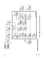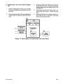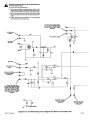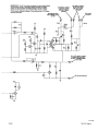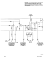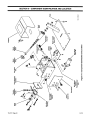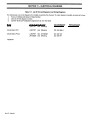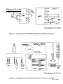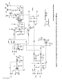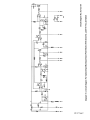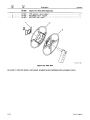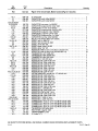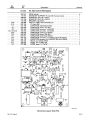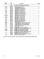
1
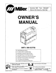
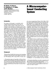
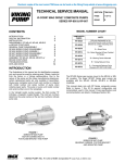
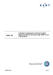
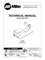
MiIIe~
November1996 Form: TM-1571
Effective With Serial No. JJ507797
TECHNICAL MANUAL
Service And Parts
S-21E
Wire Feed Equipment
A
WARNING
Use MILLER Testing Booklet (Part No.
150 853) when servicing this unit.
SERVICING can be hazardous.
• Have all service procedures performed only by
qualified persons following standard safety
practices.
U
coverjml
—
For help, call Factory
Service Department:
414-735-4505
SB-124 467
~U~r
Use only genuine MILLER replacement
parts.
FAX:
14-735-4136
U
L................J
© 1996 MILLER Electric Mfg. Co.
Or write to:
MILLER Electric Mfg. Co.
RO. Box 1079
Appleton, WI 54912 USA
PRINTED IN USA
OM-1571B
TABLE OF CONTENTS
Section No.
SECTION 1
1-1.
1-2.
1-3.
-
Page No.
SAFETY PRECAUTIONS AND SIGNAL WORDS
General Information And Safety
Safety Alert Symbol And Signal Words
Safety Precautions
1
1
1
SECTION 2- SHIPPING AND STORAGE
2-1.
2-2.
Preparation For Reshipment
Storage
2
2
SECTION 3— SPECIFICATIONS
3-1.
Description
3
SECTION 4- INSTALLATION OR RELOCATION
4-1.
4-2.
4-3.
4-4.
4-5.
4-6.
4-7.
4-8.
4-9.
4-10.
Location
Drive Roll Installation
Welding Gun Connections
Shielding Gas Installation
14-Pin Plug Connection
Welding Wire Installation
Welding Wire Threading
Adjust The Hub Tension
Welding Cable Connection
Feeding Welding Wire
3
3
5
5
6
6
7
8
8
8
SECTION 5-OPERATOR CONTROLS
5-1.
Power Switch
9
5-2.
Wire Speed Control
9
SECTION 6— SEQUENCE OF OPERATION
6-1.
6-2.
Gas Metal Arc (GMAW) And Flux Cored Arc (FCAW) Welding
Shutting Down
9
10
SECTION 7- THEORY OF OPERATION
7-1. Theory Of Operation
Diagram 7-1. Block Diagram For Wire Feeder
Diagram 7-2. Block Diagram For SpotlBurnback Time Control Option
10
11
12
—
3/91
Section No.
Page No.
SECTION 8- TROUBLESHOOTING
8-1. Testing Instruments And Information
8-2. Circuit Board Handling Precautions
8-3. Troubleshooting
Diagram 8-1. Troubleshooting Circuit Diagram For Wire Feeder
8-4. Motor Board PCi Testing Information
Diagram 8-2. Troubleshooting Circuit Diagram For Motor Control
Board PCi
8-5. Optional SpotlBurnback Board PC2 Testing Information
Diagram 8-3. Troubleshooting Circuit Diagram For Optional Spot/Burnback
Board PC2
14
14
14
16
17
18
20
22
SECTION 9- COMPONENT IDENTIFICATION AND LOCATION
Figure 9-1. Component Identification And Location
24
SECTION 10— MAINTENANCE
10-1.
10-2.
10-3.
10-4.
10-5.
SECTION 11
Routine Maintenance
Aligning Drive Roll And Wire Guide
Reinstallation Of Hub Assembly
Brush Inspection And Replacement
Overload Protection
-
25
26
26
27
27
ELECTRICAL DIAGRAMS
Diagram 11-1. Circuit Diagram For S-21 E Effective With Serial No.
JJ507797 And Following
Diagram 11-2. Wiring Diagram For S-21 E Effective With Serial No.
JJ507797 And Following
Diagram 11-3. Circuit Diagram For Motor Control Board PCi Effective
With Serial No. JJ507797 And Following
Diagram 11-4. Circuit Diagram For Optional SpotlBurnback Board PC2
Effective With Serial No. JJ507797 Thru JK742028
Diagram 11-5. Circuit Diagram For Optional Spot/Burnback Board PC2
Effective With Serial No. JK742029 And Following
29
29
30
31
32
SECTION 12— PARTS LIST
LIST OF CHARTS AND TABLES
Table 3-1. Specifications
Table 8-1. Troubleshooting
Table 10-1. Maintenance Schedule
Table 11-1. List Of Circuit Diagrams And Wiring Diagrams
3
15
25
28
SECTION 1
1-1.
-
SAFETY PRECAUTIONS AND SIGNAL WORDS
GENERAL INFORMATION AND SAFETY
This manual provides theory of operation along with
specific operating, testing, and troubleshooting procedures. It also includes precautionary information relevant to these procedures. This manual can be an effective tool in the hands of a trained serviceperson. However, it does not and cannot take the place of previous
training nor safety-conscious service work. If any doubt
arises about the specific application of procedures presented, or if problems arise which are not covered in this
manual, contact the factory Service Department before
proceeding further.
1-2.
SAFETY ALERT SYMBOL AND SIGNAL
WORDS
The following safety alert symbol and signal words are
used throughout this manual to call attention to and
identify different levels of hazard and special instructions.
This safety alert symbol is used with the signal
words WARNING and CAUTION to call attention to the safety statements.
A
A
A
WARNING statements identify procedures or
practices which must be followed to avoid serious personal injury or loss of life.
CAUTION statements identify procedures or
practices which must be followed to avoid minor
personal injury or damage to this equipment.
IMPORTANT statements identify special instructions
necessaryfor the most efficient operation of this equipment.
• Shut down unit and disconnect input power
when servicing unless the procedure specifically requires an energized unit.
• Do not leave live unit unattended.
ARC RAYS, SPARKS, AND HOT SURFACES
can burn eyes and skin; NOISE can damage
hearing.
• Wear correct eye, ear, and body protection.
FUMES AND GASES can seriously harm
your health.
• Keep your head out of the fumes.
• Ventilate to keep from breathing fumes and
gases.
• If ventilation is inadequate, use approved
breathing device.
• Read Material Safety Data Sheets (MSDSs)
and manufacturer’s instructions for any
materials used.
WELDING
wounds.
WIRE
can
cause
puncture
• Do not point gun toward any part of the body,
any conductive surface, or other personnel.
HOT METAL, SPATrER, AND SLAG can
cause fire and burns.
• Watch for fire.
• Have a fire extinguisher nearby and know
how to use it.
• Do not use near flammable material.
• Allow work and equipment to cool before
handling.
MOVING PARTS can cause serious injury.
1-3.
SAFETY PRECAUTIONS
• Keep away from moving parts.
A
WARNING: ELECTRIC SHOCK can kill.
HOT SURFACES can cause severe burns.
Do not touch live electrical parts.
• Protect yourself with dry insulating gloves
and clothing.
• Insulate yourself from ground by using
rubber9loves and insulating floormats when
power is applied to the unit.
• Allow cooling period before servicing.
5-21E
S
MAGNETIC FIELDS FROM HIGH CURRENTS
can affect pacemaker operation.
• Wearers should consult their doctor before
going near the servicing ofarc welding equipment or any arc welding operations.
TM-1571 Page 1
SECTION 2- SHIPPING AND STORAGE
PREPARATION FOR RESHIPMENT
A
WARNING: ELECTRIC SHOCK can kill.
• Do not touch live electrical parts.
• Shut down wire feeder and welding power
source, and disconnect input power employing lockout/tagging procedures before
preparing unit for shipping.
A
Lockout/tagging procedures forwire feederconsist of disconnecting interconnecting cord, and
for welding power source consist of padlocking
line disconnect switch in open position, removing fuses from fuse box, or shutting off and redtagging circuit breaker or other disconnecting
device. Stop engine, and disconnect negative
(—) battery cable from battery on welding generators.
1.
2.
Disconnect interconnecting cord from rear of wire
feeder.
Disconnect weld cable from drive assembly.
STORAGE
WARNING: ELECTRIC SHOCK can kill.
• Do not touch live electricalparts.
• Shut down wire feeder and welding power
source, and disconnect input power employing lockout/taggingprocedures before storing
unit.
Lockout/tagging procedures forwirefeederconsist of disconnecting interconnecting cord, and
for welding power source consist of padlocking
line disconnect switch in open position, removing fuses from fuse box, or shutting off and redtagging circuit breaker or other disconnecting
device. Stop engine, and disconnect negative
(—) battery cable from battery on welding generators.
1.
2.
3.
Disconnect interconnecting cord from rear of wire
feeder.
Disconnect weld cable from drive assembly.
Disconnect and remove any remote controls or
devices.
Disconnect shielding gas (and water if applicable) hoses from wire feeder.
Disconnect gun from wire feeder.
3.
Disconnect and remove any remote controls or
devices.
4.
Disconnect shielding gas (and water if applicable) hoses from wire feeder.
Disconnect gun from wire feeder.
4.
Secure welding wire to spool/reel, and remove
wire spool or reel from wire feeder.
6.
Secure welding wire to spool/reel, and remove
wire spool or reel from wire feeder.
Tape plastic around top and sides of unit.
Securely tie and/or tape cardboard over top and
around sides of unit. Use original shipping carton
if available.
IMPORTANT: Do not ship without a cardboard carton.
7.
8.
Clean outside of unit.
Remove wrapper.
5.
6.
7.
8.
Not only do costs increase dramatically but the unit is
more subject to loss or damage without a carton.
9.
If sending unit to factory, ship unit as directed by
factory Service Department or Transportation
Department.
TM-1571 Page 2
5.
9.
10.
Using dry compressed air, clean inside of unit.
Reinstall wrapper.
11.
12.
Select a storage location that least subjects the
unit to wide temperature variation, dust, dirt, and
corrosive vapors.
Carry unit to storage location.
13.
Cover unit with plastic or suitable tarp.
5-21E
SECTION 3- SPECIFICATIONS
Input Power
Table 3-1. Specifications
Electrode Wire
Wire Spool
Electrode Wire
Requirements Diameter Capacity
24 VAC
3.5 Amps
50/60 Hz
.O23thru .045 in.
(0.6 thru 1.1 mm)
Capacity
Feed Speed
Weight
Net
10 to 20 lb.
(4.5 to 9 kg)
75-600 ipm
30 lbs.
8 in. (203mm) spools (1.9-15.2 mom)
up to 60 lb.
at 24 VA~
(13.6 kg)
(27.2 kg)_coils
Ship
33 lbs.
(15 kg)
22-1(2 in.
(572 mm)
10-112 In.
(267 mm)
SB-124 467
Figure 3-1. Overall Dimensions
3-1.
DESCRIPTION
This unit is a semiautomatic constant speed wire feeder
which operates on 24 volts ac. The feeder is designed
for connection to a constant voltage (CV) type power
source through a 14-pin connector. If 115 volts ac is the
only power available for use with the feeder, the optional
power supply adapter Model PSA-2 115/24 should be
used to convert the power to 24 volts ac.
The case can be tightly latched to help keep out dust and
dirt.
SECTION 4- INSTALLATION OR RELOCATION
4-1. LOCATION (Figure 3-1)
The service life and efficiency of this unit and associated
components are reduced when they are subjected to
high levels of dust, dirt, moisture, corrosive vapors, and
extreme heat.
A proper installation site should be selected for the wire
feeder if the unit is to provide dependable service. Lead
lengths must be considered when installing the unit. A
slot isprovided in the base of the unit to fit over the lifting
eye on welding power sources so equipped. Suitable
space should be maintained around the unit for making
necessary connections and for maintenance functions.
S-21E
4-2.
DRIVE ROLL INSTALLATION (Figure 4-1)
A
WARNING: ELECTRIC SHOCK can kill.
• Do not touch live electricalparts.
• Shut down wire feeder and welding power
source, and disconnect input power employing lockout/tagging procedures before inspecting or installing.
Lockout/tagging procedures for wire feederconsist of disconnecting interconnecting cord, and
for welding power source consist of padlocking
line disconnect switch in open position, removing fuses from fuse box, or shutting off and redtagging circuit breaker or other disconnecting
device. Stop engine, and disconnect negative
(—) battery cable from battery on welding generators.
TM-1571 Page 3
Pressure Roll
Assembly
(Shown In Open
PosItion)
Hub
Wire
• Spring
9
Retaining
Ring
GunlFeeder
connector
Securing Knob
• OPTIONAL
Ret. 50497
Ref. SB-125 923
Figure 4-1. Wire Feeder Components
It is necessary to install the required drive rolls when setting up this unit and also when changing wire sizes.
Loose metal objects in this compartment may
create an electrical path between the weld output circuit and any metal surfaces or components resulting in electric shock.
IMPORTANT: Base drive rollselection on the following
recommendations:
The dual-grooved drive roll provided with the feeder accommodates.023 through .045 in. (0.6 through 1.1 mm)
wire. This drive roll has both a “‘I” groove and a “‘I”
knurled groove. Use the “V” groove for feeding .023 and
.030 in. (0.6 and 0.76 mm) wire. Use the “V” knurled
groove for feeding .035 and .045 in. (0.89 and 1.1 mm)
wire. The wire size for each groove is stamped on the
side of the drive roll. When the drive roll is installed in the
feeder, the wire size stamp for the unused groove will be
visible.
The 50 Series wire feeder style drive rolls may be used
with this feeder, but, due to the flat idler pressure roll
used, a knurled drive roll is recommended when feeding
.035 and .045 (.089 and 1.1 mm) wire.
A
WARNING: ELECTRIC SHOCK can kill.
Do not store metallic objects in this compartment. The motor drive assembly is electrically hot whenever the welding circuit is energized.
TM-1571 Page 4
IMPORTANT: Both types of 50 Series style drive rolls
can be reversed for reuse when they become worn. Reverse rolls to position unused groove(s) to feed wire.
The dual-grooveddrive rollpro vided with this feedercan
be reversed, but only to feed a different size wire.
1.
Unlatch and open left case access door.
2.
Loosen pressure adjustment knob, and pivot
knob free of pressure arm.
3.
Pivot pressure arm away to expose drive roll
carrier.
For dual-grooved roll supplied with feeder:
4.
a. Choose the proper groove.
b. Slide drive roll onto drive roll mounting hub with
chosen groove toward inside of machine. The
wire size for the unused groove will be visible
after installation.
c. Align the drive roll with holes.
d. Insert securing screws, and tighten.
5-21E
5.
For 50 Series style one-piece drive rolls:
B. Gun Trigger (Figure 5-1)
a. Slide drive roll onto drive roll mounting hub.
‘9=
b. Align drive roll with holes.
TRIGGER
RECEPTACLE
c. Insert securing screws, and tighten.
6.
For 50 Series style split drive rolls:
a. Align holes on pair of split drive rolls.
b. Insert securing screw.
c. Slide drive rolls onto drive roll mounting hub.
d. Align drive rolls with holes.
Connect gun trigger plug to trigger receptacle on the
front panel as follows: align keyways, insert gun plug
into trigger receptacle, and rotate threaded collar fully
clockwise.
4-4.
SHIELDING GAS INSTALLATION (Figures
4-2 And 4-3)
A
WARNING: PRESSURIZED CYLINDERS can
rupture causing serious personal injury and
loss of life; FALLING CYLINDERS can cause
serious injury and equipment damage.
e. Insert securing screws, and tighten.
IMPORTANT: Horizontal alignment of the drive roll on
the drive roll mounting hub with the wireguide is factory
set andshould not require readjustment. If readjustment
becomes necessary, see Section 10-2.
7.
Close and secure left case access door.
4-3.
WELDING GUN CONNECTIONS (Figures 4-1
And 5-1)
A
WARNING: ELECTRIC SHOCK can kill.
• Do not touch live electricalparts.
• Shut down wire feeder and welding power
source, and disconnect input power employing lockout/tagging procedures before working on feeder.
Lockout/tagging procedures forwire feeder consist of disconnecting interconnecting cord, and
for welding power source consist of padlocking
line disconnect switch in open position, removing fuses from fuse box, or shutting off and redtagging circuit breaker or other disconnecting
device. Stop engine, and disconnect negative
(—) battery cable from battery on welding generators.
IMPORTANT: A hole isprovided in the nameplate form-
stallation of a gun requiring an opening for an external
gas line. Remove snap-in blank before installation.
A. Gun Connector To Drive Assembly (Figure 4-1)
1.
Unlatch and open left case access door.
2.
Loosen gun/feeder connector securing knob on
the wire drive housing.
3.
Insert gun/feeder connector through the access
hole in the front panel.
4.
Insert gun/feeder connector into drive housing
with the outlet wire guide as close to the drive rolls
as possible without touching, and tighten the securing knob.
5.
S-21E
• Keep cylinders away from welding or other
electrical circuits.
• Neverallow a welding electrode to touch any
cylinder.
• Always fasten cylinder securely to running
gear bracket, a wall, or other stationary support.
Close and secure left case access door.
A. Gas Cylinder (Customer Supplied)
Chain the cylinder to a wall or other stationary support to
prevent the cylinder from falling over and breaking off
the valve. If optional power source running gear is used,
secure gas cylinderto running gear with supplied chain.
B. Regulator/Flowmeter (Customer Supplied)
1.
With the cylinder securely installed, remove the
cylinder cap, stand to one side of cylinder valve,
and open valve slightly. When gas flows from cylinder, close valve. This procedure blows out dust
or dirt that may have accumulated around the
valve seat.
IMPORTANT: A gasket should be installed to prevent
leaks. Do not use lubricants or sealing agents.
2.
The regulator/flowmeter must be properly
equipped with a stem, nut connectors, and gasket for use with either CO2 cylinders or inert gas
type cylinders.
3.
Install gas regulator/flowmeter onto gas cylinder
valve; keep the face of the regulator/flowmeter
gauge in vertical position, and tighten stem nut
securely to gas cylinder valve.
4.
A shielding gas fitting is provided on the rear of
the wire feeder. Obtain a suitable hose with
5/8-18 right- hand fitting. Attach one end of the
gas hose to this fitting. Attach the other end of the
gas hose to the regulator/flowmeter.
TM-1571 Page 5
Flow
Adjustment
Gas cylinder
Valve
Argon or Argon
CO
2 Washer
Mix cylinder
CO2 cylinder
CO2 Installation
Argon Installation
Figure 4-2. Typical RegulatorlFlowmeter Installation
14-PIN PLUG CONNECTION (Figures 4-3 And
4-4)
The 14-pin plug PLG1 00, on the end of the interconnecting cord, provides a junction point for connecting the
wire feeder to a welding power source. This connection
provides 24 volt ac power, and contactor control when
used with a constant voltage (CV) power source with a
14-pin receptacle. To make connections, align keyway,
insert plug, and rotate threaded collar fully clockwise.
SB-109 492
4-5.
The pins on plug PLG 100 are defined in relation to both
the power source and wire feeder. The welding power
source provides six functions to the wire feeder. The
pins are designated as follows:
Pin A: Up to 10 amperes of 24 volts ac, 60 Hz, with respect to socket G (circuit common); protected by fuse in
welding power source.
Ref. S-0004
Figure 4-4. Front View Of 14-Pin Plug With Pin
Locations
4-6.
WELDING WIRE INSTALLATION (Figure 4-5)
A
WARNING: ELECTRIC SHOCK can kill.
Pin B: 24 volts ac input power to energize the weld contactor. The feeder sends back 24 volts ac by means of a
contact closure from pin A to pin B.
• Do not touch live electrical parts.
• Shut down wire feeder and welding power
source, and disconnect input power employing lockout/tagging procedures before working on feeder.
Lockout/tagging procedures forwire feeder consist of disconnecting interconnecting cord, and
for welding power source consist of padlocking
line disconnect switch in open position, removing fuses from fuse box, or shutting off and redtagging circuit breaker or other disconnecting
device. Stop engine, and disconnect negative
(—) battery cable from battery on welding generators.
Pin G: 24 volts ac circuit common; also connected to
welding power source chassis.
IMPORTANT: The remaining pins in the receptacle are
not used by the feeder.
Wire Feed
Shielding Gas
valve Fitting,
A
CAUTION: LOOSE WELDING WIRE can
cause Injury.
• Keep a firm hold on the wire during installation, removal, and threading operations.
Spooled wire has a tendency to unravel rapidly
when loosened from the spool.
Weld Cable
Connection
Opening
14-Pin
Plug
Figure 4-3. Rear Panel View
TM-1571 Page 6
SA-125 924
IMPORTANT: If it should become necessaryto replace
any part of the hub assembly see hub assembly reinstallation instruction in Section 10-3.
5-21E
A. Installation Of Spool-Type Wire (Figure 4-1)
1.
Remove retaining ring from hub.
2.
Slide wire spool on hub so that wire feeds off the
bottom of the spool.
3.
Rotate wire spool until hole in spool slides over
pin in hub and seats against back flange of the
hub.
4.
Insert optional compression spring if required.
5.
Reinstall retaining ring to secure wire spool on
hub.
4-7.
WELDING WIRE THREADING
A
WARNING: ELECTRIC SHOCK can kill;
MOVING PARTS can cause injury.
The welding wire and all metal parts in contaci
with it are energized while welding.
WELDING WIRE can cause puncture
Wounds; HOT SURFACES can burn skin.
• Do not depress gun trigger untll instructed tc
do so.
• Do not point gun toward any part of the body
any conductive surface, or other personne.
when threading welding wire.
• Allow gun to cool before touching.
B. Installation Of Optional Wire Reel And ReelType Wire (Figure 4-5)
1.
Remove retaining ring and, if applicable, wire reel
assembly from hub.
2.
Lay wire reel assembly flat on a table or floor.
3.
Remove spanner nut from wire reel assembly.
4.
Remove wire retainer, and install wire onto wire
reel. Be sure that wire feeds off bottom of reel.
5.
Reinstall wire retainer and spanner nut onto wire
6.
reel.
Slide wire reel assembly onto hub, and rotate assembly until hub guide pin is seated in reel.
7.
Reinstall retaining ring onto hub.
• Do not touch live electrical parts.
• Keep clear of pinch points.
• Do not energize welding powersource orwirE
feeder until instructed to do so.
FLYING DIRT AND METAL PARTICLES can
injure personnel and damage equipment.
• Point gun liner only in a safe direction awaj~
from personnel and equipment when clean~
ing with compressed air.
Blow out the gun wire 9uide liner with compressed air when changing wire. This will remove any metal chips and dirt that may have accumulated.
A
CAUTION: LOOSE WELDING WIRE can
cause Injury.
• Keep a firm hold on the wire during installation, removal, and threading operations.
Spooled wire has a tendency to unravel rapidly
when loosened from the spool.
•Wlre Retainer
1.Install the wire as instructed in Section 4-6.
• Spanner
Nut
2.
Cut off any portion of the free end of the wire
which is not straight. Be sure that the cut end is
free from rough surfaces to permit proper feeding.
3.
Adjust hub tension according to Section 4-8 if
necessary.
4.
Loosen the pressure adjustment knob on the wire
drive housing, and pivot the pressure arm open.
5.
Feed the wire through the inlet wire guide, past
the drive rolls, and on into the gun. Feed approximately 4 inches (102 mm) of wire into the gun.
6.
Close the pressure lever, and secure with pressure adjustment knob making sure the welding
wire is in the drive roll groove and properly
aligned with the inlet and outlet guides (outlet
guide is part of gun).
7.
Tighten the pressure adjustment knob to obtain
the proper clamping pressure on the welding
wire. Do not overtighten. Further adjustment can
• OPTIONAL
SC-127 306
Figure 4-5. Optional Wire Reel And Reel-Type Wire
Installation
S-21E
TM-1571 Page 7
be made when the wire feeder is put into
operation.
4-8.
:ause
KeepInjury.
a firm hold on the wire during installa-
tion, removal, and threading operations.
Spooled wire has a tendency to unravel rapidly
when loosened from the spool.
Check the hub tension by slowly pulling the wiretoward
the drive roll. The wire should unwind freely, but have
sufficient tension to keep the wiretaut and prevent backlash when wire feeding stops. If adjustment is necessary, loosen or tighten the hex nut on the end of the hub
support shaft accordingly.
4-9.
WELDING CABLE CONNECTION
WARNING: ELECTRIC SHOCK can kill.
A
3.
4.
• Do not depress gun trigger until instructed to do
so.
• Do not point gun toward any part of the body
any conductive surface, or other personnel
when threading welding wire.
• Allow gun to cool before touching.
ADJUST THE HUB TENSION (Figure 4-1)
CAUTION: LOOSE WELDING WIRE can
A
1.
2.
WELDING WIRE can cause puncture Wounds;
HOT SURFACES can burn skin.
• Do not touch live electrical parts.
• Shut down wire feeder and welding power
source, and disconnect input power employing lockout/tagging procedures before making weld cable connections.
Lockout/tagging procedures forwire feederconsist of disconnecting interconnecting cord, and
for welding power source consist of padlocking
line disconnect switch in open position, removing fuses from fuse box, or shutting off and redtagging circuit breaker or other disconnecting
device. Stop engine, and disconnect negative
(—) battery cable from battery on welding generators.
Unlatch and open left case access door.
Route weld cable through weld cable connection
opening on rear of unit (see Figures 4-1 and 4-3).
Connect end of cable to terminal on bottom of
drive assembly. Be sure that terminal is clean
and bolt is secure.
Close and secure left case access door.
1.
Be sure wire is installed as instructed in Section
4-7.
2.
Be sure gun is installed according to Section 4-3
of this manual and the gun Owner’s Manual.
3.
Cut off any portion of the free end of the wire
which is not straight. If necessary, straighten wire
to remove cast. Be sure that the cut end is free
from rough surfaces to permit proper feeding.
Lay gun cable assembly out flat and straight (no
coils in the cable/conduit).
4.
5.
Energize the welding power source.
6.
Place the wire feeder POWER switch in the ON
position.
A
• Do not touch wire feeder case ifgun trigger is
pressed, and wire does not feed.
• If wire stops feeding, tum off welding power
source, and determine the cause.
• Correctanyhub tension, jammed wire, orgun
liner damage problems before trying to continue welding.
7.
Press the gun trigger (see WARNING block atbeginning of the Section). Wire feeds if drive roll
pressure is properly adjusted to prevent slippage.
If wire slippage is noticed, adjust hub tension according to Section 4-8. If excessive pressure is
required, check gun contact tube and gun liner for
correct size or obstructions. Release the trigger
when welding wire extends approximately one
inch (25 mm) out of gun tip.
8.
Shut down wire feeder and welding power
source.
4-10. FEEDING WELDING WIRE
A
WARNING: ELECTRIC SHOCK can kill;
MOVING PARTS can cause Injury.
• Do not touch live electrical parts.
• Keep away from pinch points.
• Do not energize welding powersource or wirE
feeder until instructed to do so.
The welding wire and all metal parts in contaci
with it are energized while welding.
TM-1571 Page 8
WARNING: ELECTRIC SHOCK can kill; TANGLED WELDING WIRE can touch case causing Welding power source open-circuit voltage to be present on case if gun trigger is
pressed.
S-21E
SECTION 5- OPERATOR CONTROLS
5-1.
POWER SWITCH (Figure 5-1)
POWER
Access Hole For
Gun/Feeder Connector
The POWER switch functions as the ON/OFF switch for
the wire feeder.
5-2.
WIRE SPEED CONTROL (Figure 5-1)
WIRE SPEED
Gun Trigger
Receptacle
ojo
Wire Speed
Control
88-124 467
Figure 5-1. Control Panel View
The WIRE SPEED control adjusts the wire feed speed
in inches per minute within the wire speed range. Rotating the WIRE SPEED control clockwise increases wire
feed speed. The scale is calibrated in inches per minute.
SECTION 6— SEQUENCE OF OPERATION
6-1.
A
GAS METAL ARC (GMAW) AND FLUX
CORED ARC (FCAW) WELDING
WARNING: ELECTRIC SHOCK can kill;
MOVING PARTS can cause serious injury;
EXPOSURE TO ENVIRONMENT can damage
internal parts.
• Do not touch live electrical parts.
• Keep case closed while operating.
Warranty is void if the wire feeder is operated
with any portion of the outer enclosure open or
removed.
ARC RAYS can burn eyes and skin; NOISE
can damage hearing.
• Wear correct eye, ear, and body protection.
FUMES AND GASES can seriously harm
your health.
• Ventilate to keep from breathing fumes and
gases.
• If ventilation is inadequate, use approved
breathing device.
HOT METAL, SPATrER, AND SLAG can
cause fire and burns.
• Watch for fire.
• Keep a fire extinguisher nearby and know
how to use it.
• Allow work and equipment to cool before
handling.
MAGNETIC FIELDS FROM HIGH CURRENTS
can affect pacemaker operation.
5-21 E
• Wearers should consult their doctor before
going near arc welding gouging, or spot
welding operations.
WELDING
Wounds.
1.
2.
3.
4.
9.
can
cause
puncture
• Do not point gun toward any part of the body
any conductive surface, or other personnel.
Install and connect unit according to Section 4.
Wear dry insulating gloves and clothing.
Connect work clamp to clean, bare metal at workpiece.
Rotate WIRE SPEED control to desired position
(see Section 5-2).
A
5.
6.
7.
8.
WIRE
WARNING: ELECTRIC SHOCK can kill.
• Do not touch live electrical parts.
• Do not touch welding wireorany metal part in
contact with it while welding.
The welding wire and all metal parts in contact
with it carry weld output when the welding power
source contactor is energized.
Energize the welding power source or generator.
Place the POWER switch in the ON position
Turn on shielding gas at the source, if applicable.
Wear welding helmet with proper filter lens
according to ANSI Z49.1.
Hold tip of gun approximately 1/2 in. (13 mm)
from workpiece, and depress gun trigger. Current
flows, gas flows, and wire feeds. If wire slippage
is noticed, adjust drive roll pressure according to
Section 4-7.
TM-1571 Page 9
A
WARNING: ELECTRIC SHOCK can kill;
TANGLED WELDING WIRE can touch case
causing welding power source open-circuit
voltage to be present on case if gun trigger is
pressed.
• Do not touch wire feeder case ifgun trigger is
pressed and wire does not feed.
• If wire stops feeding, turn off welding power
source, and determine the cause.
• Correctanyhub tension,jammed wire, orgun
liner damage problems before trying to
continue welding.
6-2.
SHUTTING DOWN
1.
Stop welding.
2.
Place POWER switch in the OFF position.
3.
Shut down welding power source or generator.
4.
Turn off shielding gas at source, if applicable.
A
WARNING: HIGH CONCENTRATION OF
SHIELDING GAS can harm health or kill.
• Shut off gas supply when not in use.
SECTION 7- THEORY OF OPERATION
7-1. THEORY OF OPERATION
IMPORTANT: The following Theory Of Operation is
written in steps which match the circled numbers on Diagrams 7-1 and 7-2.
10.
11.
A. Wire Feeder Without Options (Diagram 7-1)
1.
2.
3.
4.
5.
6.
7.
8.
9.
The 14-pin plug PLG100 on the end of the interconnecting cord provides 24 volts ac input power
from the welding power source and provides contactor control to the welding power source.
POWER switch 51 provides on/oft control of 24
volts ac input power to the wire feeder.
Circuit breaker CB1 provides overload protection
for the wire feeder.
Motor Board PCi regulates the speed of wire
drive motor Ml as set by WIRE SPEED control
R32. PCi also controls gas valve 051 and welding power source contactor via control relay
CR1.
Gas valve 051 provides shielding gas during the
weld cycle.
Integrated rectifier SRi converts the 24 volts ac
input power to a rectified 35 volts dc.
Capacitor Cl provides filtering for the 35 volts dc.
Voltage regulator VR1 reduces the 35 volts dc input voltage to 24 volts dc for control circuitry on
PCi and trigger receptacle RC1 01.
Trigger receptacle RC1 01 provides the trigger input signal to the motor stop/start circuitry.
TM-1571 Page 10
12.
13.
14.
15.
16.
17.
18.
19.
20.
21.
Motor stop/start circuitry provides input to the
brake turn on ramp, phase modulation, and control relay circuitries.
Control relay CR1 controls gas valve 051 and the
welding power source contactor through 14-pin
plug PLG100.
Brake circuitry transistor Q7 provides an electrical path for motor current during braking.
Turn on ramp provides power to WIRE SPEED
control R32.
WIRE SPEED control R32 provides a signal to
the comparator circuitry to control the wire speed.
Feedback circuitry provides comparator circuitry
with a feedback signal of actual motor voltage.
Comparator circuitry compares feedback signal
to R32 control signal and adjusts phase modulation circuitry accordingly.
Phase reset transistors Q5 and Q6 reset the timing of phase modulation.
Unijuction transistor Qi creates the phase modulation from the charging of capacitor ClO.
Pulse transformer Ti transfers the phase modulated signal to the gates of SCRi and SCR2.
Drive SCR’s SCRi and SCR2 turn on from the
phase modulation signal and supply power to
wire drive motor Mi.
Wire drive motor Ml feeds the welding wire.
S-21E
0
4-
0.
0
•1~
0
4-
1~
4)
4)
LI4)
I-
0
U-
E
(U
I0)
(U
0
0
1~
E
(U
0)
(U
0
-A
c~ .~
~(i)
.~Q)
tb~.
~3O
c~o
I—0
ZQ)
S-21E
TM-1571 Page 11
B. SpotlBurnback Time Control Option (Diagram
7-2)
1.
2.
Optional Spot/Burnback Board PC2 provides
control of spot weld time and adjustment of burnback time.
Burnback potentiometer R26 allows adjustment
of the burnback time between 0.02 and 0.25 seconds.
3.
4.
5.
Spot time potentiometer R25 allows adjustment
of spot time from 0.12 to 2.5 seconds or 0.25 to 5
seconds depending on the setting of Spot Time
DIP Switch Sl.
Spot/Continuous switch S51 allows either a normal untimed weld cycle or a timed spot weld
cycle.
Spot time DIP switch 51 provides a selection of
short range (0.12 to 2.5 seconds) or long range
(0.25 to 5 seconds) spot time.
Diagram 7-2. Block Diagram For Spot/Burnback Time Control Option
TM-1571 Page 12
S-21E
Notes
S-21E
TM-1571 Page 13
SECTION 8— TROUBLESHOOTING
8-1.
TESTING INSTRUMENTS AND INFORMATION
The service procedures in this manual require proper
testing instruments. Use a good quality digital voltohmmeter (DVM) with one megohm input impedance or
greater and diode check capability (use an analog VOM
for variable resistor testing). If an oscilloscope is specified, use a good quality unit with one megohm input impedance or greater. If a circuit board has a protective
coating, it will be necessary to remove coating or use
needle probes in the test area to obtain proper contact.
Recoat areas if necessary to retain corrosion protection.
Digital volt-ohmmeters (DVM’s) do not require lead polarity attention when making connections. However, the
meter may indicate a — (negative) voltage when the test
procedure specified a + (positive) voltage. If the incorrect polarity appears on the display, reverse meter lead
connections to test points.
8-2.
CIRCUIT BOARD HANDLING PRECAUTIONS
A
WARNING: ELECTRIC SHOCK can kill.
• Do not touch live electrical parts.
• Shut down wire feeder and welding power
source, and disconnect input power employing lockout/tagging procedures before
inspecting, maintaining, or servicing.
Lockout/tagging procedures forwirefeederconsist of disconnecting interconnecting cord, and
for welding power source consist of padlocking
line disconnect switch in open position, removing fuses from fuse box, or shutting off and redtagging circuit breaker or other disconnecting
device. Stop engine, and disconnect negative
(—) battery cable from battery on welding generators.
MOVING PARTS can cause serious injury.
• Keep away from moving parts.
HOT SURFACES can cause severe burns.
• Allow cooling period before servicing.
A
CAUTION: ELECTROSTATIC DISCHARGE
(ESD) can damage circuit boards.
• Put on properly grounded wrist strap
BEFORE handling circuit boards.
• Transport circuit boards in proper staticshielding carriers or packages.
• Perform work only at a static-safe work area.
8-3.
TROUBLESHOOTING (Table 8-1 And Diagram 8-1)
A
WARNING: ELECTRIC SHOCK can kill.
• Do not touch live electrical parts.
• Shut down wire feeder and welding power
source, and disconnect input power employing lockout/tagging procedures before
inspecting, maintaining, or servicing.
Lockout/tagging procedures forwire feeder consist of disconnecting interconnecting cord, and
for welding power source consist of padlocking
line disconnect switch in open position, removing fuses from fuse box, or shutting off and redtagging circuit breaker or other disconnecting
device. Stop engine, and disconnect negative
(—) battery cable from battery on welding generators.
MOVING PARTS can cause serious injury.
• Keep away from moving parts.
HOT SURFACES can cause severe burns.
• Allow cooling period before servicing.
Troubleshooting to be performed only by
qualified persons.
The troubleshooting table is designed to diagnose some
of the troubles that can develop in this wirefeeder. Any
circuit normally tied to ground must be at ground potential.
Use the table in conjunction with the diagrams in this
manual and the exploded views and component values
in the Service Parts Manual while performing troubleshooting procedures.
When replacing components, use only genuine MILLER
replacement parts. MILLER parts are required for warranty repair by authorized warranty service agency.
Resistance and continuity measurements must be
made with the unit shut down. Isolate components before making resistance and continuity measurements.
IMPORTANT: Beforebeginning troubleshootingproce-
• Be sure that plugs are properly installed and
aligned.
dures, visually examine internalcomponents forsigns of
overheating and failure. Many majorproblems, such as
winding(s) failure are usually apparent bydiscoloration,
smoke, and smell. Fortunately most electricalproblems
are relatively simple: blown fuses, trippedcircuit breakers, incorrect switch positions, loose connections, corrosion, and the like. A complete, careful inspection often
saves considerable time, money and frustration.
EXCESSIVE PRESSURE can break circuit
board.
IMPORTANT: Be sure that all connections are correct
INCORRECT INSTALLATION or misaligned
plugs can damage circuit board.
• Use only minimal pressure and gentle movement when disconnecting or connecting
board plugs and removing or installing board.
TM-1571 Page 14
and secure according to Section 4 and that all controls
and switches are in proper positions before proceeding
with troubleshooting.
S-21E
Table 8-1. Troubleshooting
TROUBLE
Wire does not feed.
CAUSE
REMEDY
Check gun liner, hub tension, and drive roll
pressure (see Section 4). Reset CBl (see Sec
tion 10-5).
Loose or improperly made gun Check gun trigger connection (see Section
trigger connection.
4-3).
Gun trigger.
See gun Owner’s Manual.
Welding gun shorted.
Repair or replace welding gun.
Motor Ml.
Check connections for continuity to Ml. Check
motor brushes (see Section 10-4). Replace Ml
if necessary.
Motor Control Board PCi or
Check connections for continuity to PCl.
poor connections to PCl.
Check PCi according to Diagram 8-2 and Sec
tion 8-4. Replace PCl if necessary.
Wire feeds erratically.
Pressure on drive roll is insuf- Rotate pressure adjustment knob counter
ficient.
clockwise in 1/4 turn increments until the wire
stops slipping (see Section 4-2).
Drive roll wrong size for wire
Change to correct size drive roll (see Section
size used.
4-2).
Drive rolls worn.
Replace drive rolls (see Section 4-2).
Dirt in drive rolls.
Clean drive rolls (see Section l0-lC).
Motor Control Board PCl or
Check connections for continuity to PCi.
poor connections to PCi.
Check PCi according to Diagram 8-2 and Sec
tion 8-4. Replace PCi if necessary.
Wire feeds but there is no gas Gas valve GSl.
Check GS1 for proper coil voltage and connec
flow.
tions (see Diagram 8-1). Check continuity of coil.
Replace GSl if necessary.
Motor Control Board PCl or
Check connections for continuity to PCl.
poor connections to PCl.
Check PCl according to Diagram 8-2 and Sec
tion 8-4. Replace PCl if necessary.
Wire does not feed until trigger Welding gun is shorted beRepair or replace welding gun.
is pulled but continues to feed tween one of the trigger leads
after trigger is released.
and weld cable.
Gun nozzle opening restricted. Weld spatter or foreign matter Carefully remove any weld spatter or foreign
accumulation.
matter which may accumulate around the
nozzle opening. Use a hardwood stick, never a
metal tool.
The gas valve in the feeder is Welding gun is shorted beRepair or replace welding gun.
rattling loudly along with possi- tween one of the trigger leads
ble erratic or slow wire feed
and weld cable.
speed.
Motor runs but wire is not ener- Spot/Burnback Board PC2 or Check connections for continuity to PC2. Check
gized with Spot/Burnback Op- poor connections to PC2.
PC2 according to Diagram 8-3 and Section 8-5.
tion installed.
Replace PC2 if necessary.
5-21E
Circuit breaker CB1.
TM-i 571 Page 15
)
a
~U)
~Z
~
&Ea~ ~
~
~e
O
O
O
O~,
0,
c
ow
~
~
s.a
—
=
~
~
~
O~
ca
a~
zz:~~
O~
~
Ci)
21
0
~
..~
!FI
—
~
—
C’J
—
CO
o1t~
+oO
0
~
~
~
N
—
—
~
U)
0
(oIr-~0)
L
—
—
—
CO
~
;
;
—
—
in
—
in
0)
LI4)
II-
0
IL
E
(U
I0)
0
4-
0
I0)
4-
0
0
(0
4
.0
0
I-
L
0
.~
(n
I—
0.
0..o
.-
Ci)
0)
~
~
.~
Oc~
C,
z
~Q)
E(U
I..
0)
(U
=0
0
0.
a
•c~~—-a--
U
o
0
~
o
~0
~
Q~0~n~
0
~
•
~
0.
0
-.
0
~
1110
~
q~00
~-0)0)
~
-~
0~
•~
0
UJ:
0
~-n’
Ci)~
—
a
a
S
0
I
TM-1571 Page 16
S
S
S
OJ
>
CO
>
S-21E
8-4.
A
MOTOR BOARD PCi TESTING INFORMATION (Figure 8-1 And Diagram 8-2)
W ARNING: ELECTRIC SHOCK can kill.
Do not touch live electrical parts.
• Shut down wire feeder and welding power
source or stop engine before making or
changing meter lead connections and before
disconnecting or connecting any leads.
MOVING PARTS can cause serious injury.
2.
3.
4.
Check that jumper plug PLGl is secure in receptacle RC1 on Motor Control Board PCl.
Check that plug PLG2 is secure in receptacle
RC2 on Motor Control Board PCl.
Check that plug PLG3 is secure in receptacle
RC3 on Motor Control Board PCl.
Check that plug PLG4 is secure in receptacle
RC3 on Motor Control Board PCi.
B. Power Supply Circuit
HOT SURFACES can cause severe burns.
Input power of 24 volts ac should be present between
pins A and B of receptacle RC4. If 24 volts ac are not
present, check POWER switch 51 and circuit breaker
CBl for proper operation with an ohmmeter.
An output voltage of +24 volts dc should be present at
pin A of receptacle RC2 with respect to circuit common.
If +24 volts dc are not present at pin A, replace Motor
Control Board PCl.
An output voltage of +6.5 volts dc should be present at
pin C of receptacle RC2 with respect to circuit common
with gun trigger pressed. If +6.5 volts dc are not present
at pin C, replace Motor Control Board PCi.
CAUTION: ELECTROSTATIC DISCHARGE
(ESD) can damage circuit boards.
• Put on properly grounded wrist strap BEFORE handling circuit boards.
• Transport circuit boards in proper staticshielding carriers or packages.
• Perform work only at a static-safe work area.
INCORRECT INSTALLATION or misaligned
plugs can damage circuit board.
• Be sure that plugs are properly installed and
aligned.
EXCESSIVE PRESSURE can break circuit
board.
• Use only minimalpressure and gentle movement when disconnecting or connecting
boardplugs and removing orinstallingboard.
IMPORTANT: For all checks, be sure to test and verify
the continuity of leads between the board and the area
where check is performed. All checks shouldgo through
the connections and be actual terminal-to-terminal tests
so that bad connections or leads and corrosion are not
the problem.
5-2iE
1.
• Keep away from moving parts.
• Allow cooling period before servicing.
This procedure requires the unit to be ener~ized. Only qualified persons familiar with and
ollowing standard safety practices are to perform this testing procedure.
A
A. Preliminary Checks
C. Trigger Circuit
When the gun trigger is pressed, +19 volts dc should be
present at pin B of receptacle RC2 with respect to circuit
common otherwise the voltage at pin B should be 0 volts
dc when the gun trigger is not pressed. The trigger signal
is then supplied to pin A of receptacle RCl as a motor
start/stop control signal and also supplied to pin B of receptacle RCl to control gas valve GS1 and contactor
control relay CR1 on PCi.
D. Wire Feed Speed Circuit
The 0 to +6.5 volts dc wire feed speed command input
signal should be present at pin D of receptacle RC2. The
wire feed speed command signal is compared to the
current and voltage feedback from Motor Ml thereby
providing the proper voltage output of 0 to +24 volts dc
to wire drive motor Ml through pins D (positive) and C
(negative) of receptacle RC4. If 0 to +24 volts dc is not
present between pins C and D of RC4, replace Motor
Control Board PCi.
TM-i 57i Page 17
A
WARNING: ELECTRIC SHOCK can kill; MOVING PARTS
can cause serious injury.
• Do not touch live electrical parts.
• Shut down wire feederand welding powersource or stop
engine before making or changing meter lead connections and before disconnecting or connecting any leads.
• Have only qualified persons familiar with and following
standardsafetypracticesperform troubleshootingprocedures.
• Follow standard ESD precautions to prevent damaging
static-sensitive parts during testing.
o to 6.5 volts dc input from
mm. to max. of WIRE SPEED
control
with ~untrigger
6.5 volts dc output
Not used
+24 volts dc
output
/
+19 volts dc Input with
gun trigger preseed without
option, +24 volts dc input
with gun trigger pressed
with option, 0 volts dc input
after spot time or trigger
released
.29.1
+24 volts dc input
with gun trigger
pressed
RI & M
mwus ~e~n
Diagram 8-2. Troubleshooting Circuit Diagram For Motor Control Board PCi
TM-i 571 Page 18
S-2iE
IMPORTANT: For DC, the values are based on a good quality digital
volt-ohmmeter (DVM) or equivalent reading average (not RMS)
24 volts ac output
values. For AC, the values are RMS readings. The DC voltages
contactor control
shown are with respect to circuit common lead 24 (pin C of plug
with g
PLO4) unless otherwise indicated. The tolerances are ±10%unless
otherwise specified.
24 volts ac input
with POWER switch
51 ON
24 volts ac output
to as valve GSi
wit gun tr~ger
AC circuit
common
.241.1
DC cirucit common
+2W
5D-124 896
S-2iE
TM-i57i Page i9
Receptacle
RC3
Receptacle
RC4
SA-123 147-E
Figure 8-1. Motor Control Board PCi Component Locations And Information
8-5.
A
OPTIONAL SPOTIBURNBACK BOARD PC2
TESTING INFORMATION (Diagram 8-3 And
Figure 8-2)
MOVING PARTS can cause serious Injury.
• Use only minimal pressure and gentle movement when disconnecting or connecting
board plugs and removingor installing board.
IMPORTANT: For all checks, be sure to testand verify
the continuity of leads between the board and the area
where check is performed. Allchecks shouldgo through
the connections and be actual terminal-to-terminal tests
so that bad connections or leads and corrosion are not
the problem.
• Keep away from moving parts.
A. Power Supply Circuit
WARNING: ELECTRIC SHOCK can kill.
• Do not touch live electrical parts.
• Shut down wire feeder and welding power
source or stop engine before making or
changing meter lead connections and before
disconnecting or connecting any leads.
HOT SURFACES can cause severe burns.
• Allow cooling period before servicing.
This procedure requires the unit to be enerized. Only qualified persons familiar with and
ollowing standard safety practices are to perform this testing procedure.
Input power of +35 volts dc should be present between
pins A and B (DC circuit common) of receptacle RCl. If
+35 volts dc are not present, check that plug PLG51 is
secure in receptacle RCl on Burnback Board PC2 and
plug PLG 1 is secure in receptacle RCl on Motor Control
Board PCl. If +35 volts dc are still not present, check
Motor Control Board PCl according to Section 8-4.
CAUTION: ELECTROSTATIC DISCHARGE
(ESD) can damage circuit boards.
B. Trigger Circuit
p
A
EXCESSIVE PRESSURE can break circuit
board.
• Put on properly grounded wrist strap BEFORE handling circuit boards.
• Transport circuit boards in proper staticshielding carriers or packages.
• Perform work only at a static-safe work area.
INCORRECT INSTALLATION or misaligned
plugs can damage circuit board.
• Be sure that plugs are properly installed and
aligned.
TM-i57i Page 20
A trigger input voltage of +19 volts dc should be present
at pin D of receptacle RCl with respect to circuit common when the gun trigger is pressed, and 0 volts dc
should be present when the gun trigger is released. If
+19 volts dc are not present when the gun trigger is
pressed, check Motor Board PCi according to Section
8-4.
C. Motor StartlStop Circuit
When the gun trigger is pressed, a motor control output
voltage of +24 volts dc should be present at pin A of reS-2iE
ceptacle RC2 with respect to circuit common to start the
motor and 0 volts dc should be present when the gun
trigger is released to stop the motor. If +24 volts dc are
not present at pin A when the gun trigger is pressed, replace Spot/Burnback Board PC2.
D. Contactor Control Circuit
When the gun trigger is pressed and +19 volts dc are
present at pin D of receptacle RCl with respect to DC
circuit common, a contactor control output voltage of
+24 volts dc should be present at pin B of receptacle
RC2 with respect to circuit common. When the gun trigger is released, 0 volts dc should be present at pin B after a delay of 0 to 0.25 seconds depending on the time
set on Burnback Potentiometer R26. If +24 volts dc are
not present at pin B when the gun trigger is pressed or 0
volts dc are not present when the gun trigger is released,
replace Spot/Burnback Board P02.
Spot Time
DIP Switch
Si
SA-125 969-C
Figure 8-2. Optional SpotlBurnback Board PC2 Component Locations And Information
S-2iE
TM-1571 Page 21
A
WARNING: ELECTRIC SHOCK can kill; MOVING PARTS
can cause serious Inlury.
• Do nottouch live electrical parts.
• Shutdown wire feederand welding powersource or stop
engine before making or changing meter lead connections and before disconnecting or connecting any leads.
• Have only qualified persons familiar with and following
standardsafetypractices perform troubleshootingprocedures.
• Follow standard ESD precautions to prevent damaging
static-sensitive parts during testing.
Spot time
potentiometer
R25
UIN
GND
+35 volts dc
input
Circuit
common
TRIGGER
+19 volts dc Input with
gun trIgger pressed
/
Not used
Diagram 8-3. Troubleshooting Circuit Diagram For Optional SpotlBurnback Board PC2
TM-1571 Page 22
S-21 E
IMPORTANT: For DC, the values are based on a good quality digital
volt-ohmmeter (DVM) or equivalent reading average (not RM5)
values. ForAC, the values are RMS readings. The DC voltages
shown are with respect to DC circuit common lead 71 (pin B ofplug
PLG5 I) unless otherwise indicated. The tolerances are ±10% unless
otherwise specified.
Burnback
potentiometer
R26
common
I,
O volts dc during spot
time, 0.7 volts dc a~er
spot time with S51 in
Spot position, 0 volts
do with S51 in
contInuous position
‘4
Not used
+24 volts dc output
for motor stop/stan
circuitry with gun
trigger pressed, 0
volts dc after spot
time
Not used
+24 volts dc output
for contactor output
with gun trigger pressed,
0 volts do after
burnback time
80-125 971
S-21E
TM-1571 Page 23
SECTION 9— COMPONENT IDENTIFICATION AND LOCATION
6)
6)
‘U
Ci)
0
0.
a.
(U
0
(U
0
0
-J
4-
6)
‘S.—
0~0
• —
0
(U
.~
0
4‘44-
4)
4-
4)
0
0.
E
0
C.)
0’
4)
I0)
6)—,
&2 E~.,1
~ .2 CO
•
0.
6)
0.
6)
E
z0
TM-1571 Page 24
S-21E
SECTION 10— MAINTENANCE
10-1. ROUTINE MAINTENANCE (Table 10-1)
IMPORTANT: Every six months inspect the labels on
this unit for legibility All precautionary labels must be
maintained in a clearly readable state and replaced
when necessary. See Service Parts Manual for part
number of precautionary labels.
A
WARNING: ELECTRIC SHOCK can kill.
• Do not touch live electrical parts.
• Shut down wire feeder and welding power
source, and disconnect input power employing lockout/taggin9 procedures before inspectIng, maintaining, or servicing.
Lockout/tag9ing procedures for wire feeder
consist of disconnecting interconnecting cord,
and for welding power source consist of padlocking line disconnect switch in open position,
removing fuses from fuse box, or shutting off
and red-tagging circuit breaker or other disconnecting device. Stop engine, and disconnect
negative (—) battery cable from battery on welding generators.
• Allow gun and unit to cool before touching.
• Do not depress gun trigger while performing
maintenance on gun.
Troubleshooting to be performed only by qualified persons.
Table 10-1. Maintenance Schedule
Frequency*
Maintenance
Every Month
Units in heavy service environ
ments: Check labels, weld cables,
clean internal parts and drive rolls.
Every 6 Months Check all labels (see IMPORTANT
block, Section 10-1). Inspect q un
and cables (Section 10-1 B). Clean
drive rolls (Section l0-lC).
*Frequency of service is based on units operated 40
hours per week. Increase frequency of maintenance if
usage exceeds 40 hours per week.
A. Internal Cleaning
A
ARNING: Read and follow safety information at beginning of entire Section 10-1 before proceeding.
Every month, blow our or vacuum dust and dirt from the
inside of the wire feeder. Remove the outer enclosure,
and use a clean, dry airstream orvacuum suctionfor the
cleaning operation. If dusty or dirty conditions are present, clean the unit monthly.
Every six months, inspect the gun, hoses, and cables. If
dusty or dirty conditions are present, inspect the unit
monthly. Inspection should consist of the following:
1. Unlatch and open left case access door.
2. Inspect gun for broken areas, cracks, and loose
parts; tighten, repair, and replace as required.
3. Repair or replace, as required, all hose and cable; give particular attention to frayed and
cracked insulation and areas where hose and cables enter equipment.
4. Remove grease and grime from components,
moisture from electrical parts and cable.
A
5.
6.
A
S-21E
• Point gun liner only in a safe direction away
from personnel and equipment when cleaning with compressed air.
Blow out the gun wire guide liner with compressed air when changing wire. This will remove
any metal chips and dirt that may have accumulated.
Close and secure left case access door.
C. Cleaning Of Drive Rolls
A
WARNING: Read and follow safety information at beginning of entire Section 10-1 before proceeding.
MOVING PARTS can cause serious injury.
• Keep away from moving parts.
HIGH ROTATIONAL SPEED may cause
damage to drive rolls and injure personnel.
• Do not allow drive rollsto rotate at high speed
if compressed air is used for cleaning the
drive rollassembly
It is necessary to remove the drive rolls forpropercleaning of the wire grooves (see Section 4-2 for removal and
installation instructions). Use a wire brush to clean rolls.
IMPORTANT: Failure to properly maintain the drive rolls
can result in a buildup of wireparticles which decreases
the efficiency of the wire feeding operation.
1.
Remove the three drive roll securing screws from
each drive roll, and remove drive rolls.
2.
Using wire brush, remove the buildup of wire
particles in the wire grooves.
3.
Reinstall drive rolls according to Section 4-2.
4.
Resume operation.
B. Inspection and Upkeep
ARNING: Read and follow safety Information at beginning of entire Section 10-1 before proceeding.
CAUTION: FLYING DIRT AND METAL PARTICLES can injure personnel and damage
equipment.
TM-1571 Page 25
10-2. ALIGNING DRIVE ROLL AND WIRE GUIDE
(Figure 10-1)
A
WARNING: ELECTRIC SHOCK can kill.
Do not touch live electrical parts.
• Shut down wire feeder and welding power
source, and disconnect input power
employing lockout/tagging procedures
be ore working on feeder.
Lockout/tag9ing procedures for wire feeder
consist of disconnecting interconnecting cord,
and for welding power source consist of padlockin9 line disconnect switch in open position,
removing fuses from fuse box, or shutting off
and red-tag9ing circuit breaker or other disconnecting device. Stop engine, and disconnect
negative (—) battery cable from battery on welding generators.
MOVING PARTS can cause serious injury.
• Keep away from moving parts.
HOT SURFACES can cause severe burns.
• Allow cooling period before servicing.
Maintenance to be performed only by qualified
persons.
The drive roll and wire guide must be aligned for wireto
feed properly. Alignment isfactory set and should not require readjustment. To check alignment, compare drive
roll and wire guide positions with Figure 10-1. If alignment is necessary, proceed as follows:
Behind the drive roll mounting hub is a spring washer. To
obtain proper alignment of the drive roll with the wire
guide, rotate drive roll mounting hub securing bolt, and
move drive roll in or out until groove in drive roll lines up
with wire guide (see Figure 10-1).
Wire Guide_-
CORRECT
ALIGNMENT
Drive Roll
Washer
A
Welding Wire
V
I
Drive Roll
Mounting Hub
10-3. REINSTALLATION OF HUB ASSEMBLY (Figure 10-2)
WARNING: ELECTRIC SHOCK can kill.
A
• Do not touch live electrical parts.
• Shut down wire feeder and welding power
source, and disconnect inputpower employing lockout/tagging procedures before working on feeder.
Lockout/tagging procedures for wirefeeder consist of disconnecting interconnecting cord, and
for welding power source consist of padlocking
line disconnect switch in open position, removing fuses from fuse box, or shutting off and redtagging circuit breaker or other disconnecting
device. Stop engine, and disconnect negative
(—) battery cable from battery on welding generators.
If it should become necessary to replace any part of the
assembly, obtain part and proceed as follows to reinstall
the assembly.
1. Slide the following items onto the spool support
shaft in order given:
a. Fiber Washer
b. Brake Washer
c. Hub
d. Brake Washer
e. Fiber Washer
f. Keyed Washer
g. Spring
h. Wire Reel
i. Wire Retainer
j. Spanner Nut
k. Retaining Ring
2. Rotate bolt into support shaft. Bolt should be rotated only until a slight drag is felt while turning
hub.
3. Install retaining ring on hub.
10-4. BRUSH INSPECTION AND REPLACEMENT
WARNING: ELECTRIC SHOCK can kill.
A
View Is from top
of feeder looking
down with pressure
Lockout/tagging procedures forwire feederconsist of disconnecting interconnecting cord, and
for welding power source consist of padlocking
line disconnect switch in open position, removing fuses from fuse box, or shutting off and redtagging circuit breaker or other disconnecting
device. Stop engine, and disconnect negative
(—) battery cable from battery on welding generators.
roll assembly open
INCORRECT
ALIGNMENT
Secrurlng
Bolt
SA 145763
Figure 10-1. Reinstallation Of Hub Assembly
TM-1571 Page 26
• Do not touch live electrical parts.
• Shut down wire feeder and welding power
source, and disconnect input power employing lockout/tagging procedures before working on feeder.
1.
Remove two brush caps located on end of the
drive motor.
S-21E
2.
3.
4.
Remove brushes.
Examine brushes. Replace brushes if they are
chipped or broken or if less than 1/4 in. (6.4 mm)
of brush material remains.
Install brushes, and secure with caps.
10-5. OVERLOAD PROTECTION
Circuit breaker CBl provides protection to the feeder
circuits. CBl is located towards the front of the unit, be-
S-21E
hind the left case access door. Ifthe motor should overload or the circuit fail, the breaker would trip and shut
down the wirefeeder. If CB1 opens, correct the problem
and manually reset the breaker.
To reset CBl, proceed as follows:
1.
2.
3.
Unlatch and open left case access door.
Locate CBl, and reset (see Figure 4-1).
Close and secure left case access door.
TM-1571 Page 27
SECTION 11
-
ELECTRICAL DIAGRAMS
Table 11-1. List Of Circuit Diagrams And Wiring Diagrams
The following is a list of all diagrams for models covered by this manual. To order diagrams needed, proceed as follows:
1. Know unit Model and Serial or Style Number.
2. Use List to find diagram number.
3. Call the Technical Publications Department at 414-735-4356.
Model
Serial Or Style Number
S-21E
JJ507797 and following
Circuit Board PCl
JJ507797 and following
SD-124 896-A
Circuit Board PC2.
JJ507797 thru JK742028
JK742029 and following
SC-122 194
SC-125 971
• Optional
SM-1571 Page 28
Circuit Diagram
Wiring Diagram
SB-124 895-B
SB-l 24816-B
r
PLGIOO
A
.(~a
I
—~
~<*z~O
o-’--cX2—~----’—« mc4-A
0 ~
B
I
I
~<Rc4-B
4
‘E-.-.<~~
~<A~-0
N
2;
ACIOI
lUIGGER
Ai~-o>~WhED
Pci
I
£~G~Li< RC4-C
R~TA~.E
—
RC4-0
«mci-c
«mci-v
I
mci-a>
I
I
I
I
I
I
___
mcs-s»
mc3-A»
SPOT/BURNBACK
I
OPTION
K31
mci-v»
mci-c»
mci-o>~
mci-c ~
~AOC
~<mci-O I
I
~< mci-v
I
~< mci-c
«mci-E
mci-s >~
mci-A >~
.17
mci-A
mci-c »—l .M
RCO-A
Rca-s
~
~
BOARD
I
~< mci-A
I
I
mci-s
L
Circuit Diagram No. SB-i 24 895-B
Diagram 11-1. Circuit Diagram For S-21E Effective With Serial No. JJ507797 And Following
Wiring Diagram No. SB-i 24 816-B
Diagram 11-2. Wiring Diagram For S-21E Effective With Serial No. JJ507’797 And Following
SM-1571 Page 29
0~
I
(0
0)
(0
cr
N
0
I0
6
.5
C’)
I-
z
6
E
0
Li
z
E
Ii
U,’-
(U
I-
0)
~
~
~
~
0.j
U
0’
_
0
IL
~
I-
0’
I.0
It)
6
z
L.
S
4)
U)
4-
4)
4-
U
4)
w
C.)
I
S
a.
0
I...
(U
0
(0
.5I..
4-
C.)
0
0
4L.
IL
E
0
I0
0~
I-
0)
(U
4-
U
IC”
E(U
I..
0)
0
r
L
-,
.1
I
I
I
I-
CD
ci.
I-
0
SM-1571 Page 30
0
0’
N
N
1~
(
Cl)
6
z
E
0
(U
I-
0)
(U
0
N
0
N
I’-
4-
0
I-
G
I-
I0’
0
LI)
z6
Rca-A
4-
4)
mci-c
w
mci-c
a.
I-
(U
0
mci-c
0
(U
.0
C
MCI -F
I-
0.
U)
C
0
4-
a.
0
I-
0
IL
E
(U
0)
0
0
Iq~i
I-
E(U
L.
0)
0
mci-o
mci-n
MCI-A
SM-1571 Page 31
1~
0’
LI)
N
6
U)
6
z
E(U
0)
C
1~
0)
(U
0
o
0
IL
C
I-
0’
N
0
N
I’-
6
z
I-
4)
U)
4-
4)
0
4)
w
N
C.)
a.
0
I(U
0
0
(U
.0
C
I-
0
a.
U)
C
0
0.
4-
0
I..
0
IL
E
(U
L.
0)
(U
0
4C.)
I-
(3
E
(U
0)
I..
(U
0
SM-1571 Page 32
MiIIeE
November1996 Form: TM-1571
Effective With Serial No. JJ507797
SECTION 12- PARTS LIST
S-21E
Wire Feed Equipment
S-21E
TM-1571 Page 33
0
N
C—
Ci)
CO
.0
E
4)
U’
U,
N
in
C%J
1~
4)
I0)
IL
N
C,J
Ci)
E
a)
Ci)
a)
V
=
TM-i 571 Page 34
S-21E
Item
No.
Dia.
Mkgs.
Part
No.
Description
Quantity
Figure 12-1. Main Assembly
... 1
2
3
4
5
6
7
8
9
..10
11
12
13
..14
15
16
..17
..18
18
..19
20
20
21
22
23
.24
25
..25
26
..27
..28.... GS1
...
...
...
...
...
...
127 232 ...
151 828
112 031
111 523
114 415
092 237
089 477
085 244
089 562
010224
090416
124 817
602 243
602213
601 966
604 538
124778
124819...
130 365
090440...
604 668
601 880
010 291
107 983
071 602
010494...
092 200
131 181
...
DRIVE ASSEMBLY, wire (consisting of)
PIN, cotter-hair .042 x .750
LEVER, pressure-roll
BEARING, ball .315 x .866 x .275
SCREW, phillips-flat hd 10-24 x .625
KNOB, adjustment-tension
SPRING, cprsn .770 OD x 1.000 wire x .715p1d
WASHER, cupped stl .328 ID x .812 OD x .125 lip
FASTENER, pinned
PIN,springcs.187x1.000
PIN, hinge
HOUSING, wire drive
WASHER, flat stl std .378
WASHER, lockstlsplit.375
SCREW, cap stl hex hd .375-16 x 1.250
WASHER, flat stl SAE .312
KNOB
INSULATOR, housing drive (Prior to KA759476)
1
1
1
1
1
INSULATOR, housing-drive (Eff w/KA759476)
1
1
1
1
1
1
1
1
1
1
1
1
1
1
INSULATOR,coverhousing
NUT, stl slflkg hex med fnsh .500-20 (Prior to JK7021 58)
NUT, stl hex jam .500-13 (Eff w/JK7021 58)
WASHER, flat-nylafil .625 ID x 1.250 OD x .l2Sthk
BLANK, snap-in nyl .SOOmtg hole
LABEL, caution high frequency will damage etc
BUSHING, snap-in nyl 1.375 IDx l.7SOmtg hole
WIRE GUIDE & NUT, inlet (Prior to JK7021 58)
WIREGUIDE&NUT,(Effw/JK702158)
PLATE, identification control panel (order by model and serial number)
134834... HOSE,SAE.l87lDx.4100D(orderbyft)
109930... VALVE,24VAC2wayl/4lPSxl/8orf(PriortoJK6l7847)
...
...
...
...
...
...
010296... FITTING, hose brselb m l/4NPTx .625-l8RH (Prior to JK617847)
010 869
FITTING, pipe brs bushing 1/4 x l/8NPT (Prior to JK617847)
-
29
29
.30
- 30
.
-
31
32
33
34
35
36
- 37
37
38
.39
..40
41
..42
43
44
44
..45
.
S-21E
1
2ft
1
1
1
1
1
CATCH, link-lock (Prior to KA848999)
1
...
PLATE, keeper link-lock (Prior to KA848999)
LATCH, door (Eff w/KA848999 thru KC261 809)
CATCH, link-lock (Eff w/KC261 810 and on)
PLATE, keeper link-lock (Effw/KC261810)
WRAPPER (Priorto KC261810)
WRAPPER (Eff w/KC261 810)
LABEL, warning general precautionary
1
1
1
1
1
1
1
...
LABEL, warning electric shock can kill
1
BUMPER, polyurethane polymer .500
HUB & SPINDLE ASSEMBLY, (consisting of)
RING, retaining-spool
RING, retaining ext .625 shaft x .OSOthk (Eff w/KC237900)
WASHER, flat stl .640 ID x 1.000 OD (Eff w/KC237900)
SHAFT, spool support (Prior to KC237900)
SHAFT, spool support (Eff w/KC237900)
SPRING, compression .970 OD x .120 wire x 1.250 pld
WASHER, flat stl keyed l.SOOdia x .l2Sthk
WASHER,fbr.656lDx1.5000Dx.l2Sthk
WASHER, brake
HUB,spool
NUT, stl slflkg hex reg .625-11
BASE, (Prior to KA848999)
BASE, (Eff w/KA848999)
FOOT, rubber 1.2SOdia x 1.125 high (Prior to KA848999)
1
1
1
1
1
1
1
112090...
125785...
089 572
089 573
137 304
089 572
089573...
+122313...
152 725
134 464
090 439
126 873...
072 094
058 427
141 700
605 941
072 292
154 098
010 233
057 971
010191
058 628
058428
135 205
122 430...
137 461
122339...
...
...
- .
.
FITTING, pipe brs elb 1/8NPT x 3/16 hose (Prior to JK61 7847)
VALVE,24VAC2wayl/8orf(EffwIJK617847)
...
..28.... GS1
29
1
1
1
1
2
1
1
1
1
...
...
...
...
...
...
1
1
2
2
1
1
1
1
4
TM-i 571 Page 35
Item
No.
Dia.
Mkgs.
Part
No.
Description
Quantity
Figure 12-1. Main Assembly (Continued)
..45
134306.
..46.. PLG100.... 144310.
134732.
..47
079739.
..46.. PLG100....141 162.
134731.
..47
143922.
..48
007826.
..49
605227.
120304.
..50
115104.
..51.... CBl
123745.
..52.... PCl
123148.
PLG1
115093.
113746.
PLG2
115092
113 746
PLG3
131 054
113 746
115 094
PLG4
113 746
..53
110375...
..54
123810...
..55
092865...
..56
605308...
..57
Ml
122741...
~136745
..58
079625...
..59.... R32
073562...
..60
124720...
..60
137814...
..60
153612...
.61
..62
097922...
..63
51
111997...
..64... RC1Ol
048282...
079534...
..65
057084...
..66
058549...
..67
605758...
..68
079626...
..69
000418...
..70
602241...
..71
124818...
..71
•087130...
..71
•053695...
..71
•079726...
..71
•079728...
..72
124820...
•108008...
....
....
....
....
...
...
....
FOOT, rubber 1 .2SOdia x 1.375 high
CONNECTOR & PINS, (Prior to KB041147) (consisting of)
CONNECTOR, circ pin push-in 20-24ga Amp 21 3605-1
CONNECTOR, circ clamp str rlf 17-20 Amp 206322-2
CONNECTOR & PINS, (Eff w/KB041147) (consisting of)
CONNECTOR, circ pin push-in 14-l8ga Amp 213603-1
CONNECTOR, circ clamp str rlf size 17-20 Amp 206070-3
CABLE, No. 18/3c (order by ft)
NUT, nyl hex jam .750, (Eff w/JK617847)
BLANK, snap-in nyl .2SOmtg
CONNECTOR, clamp-cable .500
CIRCUIT BREAKER, manual reset 1 P 4A 25OVAC
CIRCUIT CARD, motor control (Fig 12-3)
CONNECTOR & SOCKETS, (consisting of)
CONNECTOR, rect skt 24-lBga Molex 39-00-0038
CONNECTOR & SOCKETS, (consisting of)
CONNECTOR, rect skt 24-l8ga Molex 39-00-0038
CONNECTOR & SOCKETS, (consisting of)
CONNECTOR, rect skt 24-l8ga Molex 39-00-0038
CONNECTOR & SOCKETS, (consisting of)
CONNECTOR, rect skt 24-lega Molex 39-00-0038
STAND-OFF, support
STAND-OFF, support
KEY, .122x.123x.750
RING, retaining
MOTOR, gear 24VDC 122RPM (consisting of)
BRUSH & SPRING ASSEMBLY
WASHER, spring stl .500
POTENTIOMETER, C l/T 2W 10K ohm
CASE ASSEMBLY, (Prior to KA848999)
CASE ASSEMBLY, (Eff w/KA848999 thru KC261 809)
CASE ASSEMBLY, (Eff w/KC261810 and on)
NAMEPLATE, (order by model and serial number)
KNOB, pointer
SWITCH, rocker SPST 1OA 25OVAC
CONNECTOR & SOCKETS, (consisting of)
CONNECTOR, circ skt push-in 14-lBga Amp 66358-6
BUSHING, snap-in nyl .250 OD x .375mtg hole
GUIDE, wire-Inlet 1/16
SCREW, mach stI rdh 10-32 x 1.000
SCREW, mach stl filh 10-32 x .875
SCREW, cap stl hex hd slf1kg .250-20 x .500
WASHER, flat stl SAE .250
ROLL, drive-combination large
ROLL, drive V-grooved .023 wire
ROLL, drive V-grooved .030 wire
ROLL, drive V-knurled .035 wire
ROLL, drive V-knurled .045 wire
HUB, mtg-roll drive
REEL, wire (Fig 12-2)
-
+When ordering a component originally displaying a precautionary label, the label should also be ordered.
4
1
14
1
1
14
1
llft
1
3
1
1
1
1
6
1
8
1
2
1
4
2
2
1
1
1
2
2
1
1
1
1
1
1
1
1
4
1
1
3
3
1
1
1
1
1
2
2
1
1
*Recommended Spare Parts.
• OPTIONAL
BE SURE TO PROVIDE MODEL AND SERIAL NUMBER WHEN ORDERING REPLACEMENT PARTS.
TM-1571 Page 36
S-21E
Item
No.
Part
Description
No.
108 008
1
2
3
Quantity
Figure 12-2. Reel, Wire (Optional)
124904...NUT,spanner-spoolsupport
124 905.. RETAINER, spool support
124 900
SUPPORT, reel - spool
1
1
1
-
..
1
2
3
Ref. 5C-127 305
Figure 12-2. Reel, Wire
BE SURE TO PROVIDE MODEL AND SERIAL NUMBER WHEN ORDERING REPLACEMENT PARTS.
S-21E
TM-1571 Page 37
SA-123 147-F
Figure 12-3. Motor Control Circuit Card PCi
TM-1571 Page 38
S-21E
Dia.
Mkgs.
Part
No.
PCi
123 148
A1,2
Cl
C2
C3,6,37,38,50
51,53-56,59
C4,5,8
C7,12
C9
ClO
Cli
C52
C60-62
CR1
D1,2,8,12
D3
D5
D6,7,9,10
Dli
009159
039482
039481
....
....
...
Ji-lO
01
Q4,5,6
07
R2
R3,5,7,8
R4,31
R6,22
R9,17,33
RiO
Ru
R12,14,24,26,40
R13
Ri 5,35
R16
RiB
R19
R20
R21
R23
R25
R29
R30
R32
R34
R50,53,56
R51 ,52,54,55
RC1
.... RC2
RC3
RC4
SCRi ,2
SRi
Ti
VR1
...
...
...
....
...
....
...
...
....
....
....
...
....
...
...
....
....
....
.
122723
119198
000340
077206
031 693
035522
119197
053 991
099018
026202
087294
037250
028351
032210
092 648
092648
039355
037 200
121129
028284
093 037
044 789
072 559
000885
035829
035888
072560
006424
035 828
052 143
093 041
093 030
052 139
039 106
108 437
030 105
084 205
030 098
072 677
108 436
605 919
605 918
114 654
113 749
117 038
113 748
080 508
121 131
111 910
091 256
Description
Quantity
Figure 12-3. Circuit Card, Motor Control (Fig 12-1 Item 52)
...
...
...
...
...
...
...
...
...
...
...
...
...
...
...
...
...
...
...
...
...
...
...
...
...
...
...
...
...
...
...
...
...
...
...
...
...
...
...
...
...
...
IC, linear 358
CAPACITOR, elctlt iQOuf 35VDC
CAPACITOR, elctlt 3.3uf 50VDC
2
1
1
CAPACITOR, cer mono .luf 5OVDC
CAPACITOR, polye met film .33uf 100V
CAPACITOR, cer disc .01 uf 5OVDC
CAPACITOR, polye met film .0047uf 100V
CAPACITOR, polye film .33uf 1 OOVDC
CAPACITOR, polye film .047uf 1 OOV
CAPACITOR, polye met film .luf 100V
CAPACITOR, cer disc .OSuf 500VDC
RELAY, end 24VDC SPDT 5A 1 20VAC
DIODE, rect 1A400VSP
DIODE, fast recovery3A400V
DIODE, zener24V 1W
DIODE, signal .020A 75V SP
DIODE,zenerlOVlW
RESISTOR, WWfxd zero ohm (Prior to KC301174)
RESISTOR, WW fxd zero ohm (Eff w/KC301174)
TRANSISTOR, UJT 1 5MA 40V
TRANSISTOR, NPN 200MA 40V
TRANSISTOR, NPN iQA 100V
RESISTOR, C .5W 27K ohm
RESISTOR, ME .25W 47.5K ohm
RESISTOR, ME .25W lOOK ohm
RESISTOR, ME .25W22.1K ohm
RESISTOR, ME .25W 10K ohm
RESISTOR, ME .25W 1.5K ohm
RESISTOR, CE .25W 2.2K ohm
RESISTOR, ME .25W 1K ohm
POTENTIOMETER, cermet trmr 1/T .5W 2K ohm
RESISTOR, ME .25W 243 ohm
RESISTOR, ME .25W 162K ohm
RESISTOR, ME .25W 150K ohm
RESISTOR, ME .25W 15K ohm
RESISTOR, ME .25W 39.2K ohm
RESISTOR, CF .25W 470 ohm
RESISTOR, MF .25W 4.75K ohm
RESISTOR, C .5W 680 ohm
RESISTOR, ME .25W 3.32K ohm
RESISTOR, WW fxd 5W 1 ohm
RESISTOR, ME .25W 33.2K ohm
RESISTOR, ME .25W 4.32K ohm
RESISTOR, C .25W 47 ohm
RESISTOR, C .25W 100 ohm
CONNECTOR, rect 6 pin 2 row rcpt Molex 39-28-1063
CONNECTOR, rect 8 pin 2 row rcpt Molex 39-28-1 083
CONNECTOR, rect 2 pin 2 row rcpt Molex 39-28-1 023
CONNECTOR, rect 4 pin 2 row rcpt Molex 39-28-1043
THYRISTOR, SCR 8.5A 200V
RECTIFIER, integ 8A 100V
TRANSFORMER, pulse
IC, linear 317L
11
3
2
1
1
1
1
3
1
4
1
1
4
1
12
10
1
3
1
1
4
2
2
3
1
1
5
1
2
1
1
1
1
1
1
1
1
1
1
1
3
4
1
1
1
1
2
1
1
1
BE SURE TO PROVIDE MODEL AND SERIAL NUMBER WHEN ORDERING REPLACEMENT PARTS.
5-21E
TM-1571 Page 39
Dia.
Mkgs.
Part
No.
Description
Quantity
Kit, Spot Control (Field Option)
121 562
093 551
KNOB, pointer
110 375
STAND-OFF SUPPORT, PC Card No 6 screw w/post
098 691
STAND-OFF, No 6-32 x .500 Ig
073 756
STAND-OFF, No 6-32 x .625 Ig
122 426
BRACKET, mtg options
125 968
CIRCUIT CARD, timer (consisting of)
009159.... IC, linear358
031 708
CAPACITOR, elctlt 220uf 5OVDC
000 348
CAPACITOR, tantlm .47uf 35V
083 182
CAPACITOR, cer mono .iuf 5OVDC
122 723
CAPACITOR, cer mono .luf 5OVDC
032 820
CAPACITOR, tantlm 2.2uf 35VDC
000 347
CAPACITOR, tantlm .33uf 35V
031 677
CAPACITOR, tantlm 5.6uf 35VDC
084 128
CAPACITOR, cer mono .01 uf 5OVDC (Eff w/JK742029)
044 176
CAPACITOR, cer disc .01 uf 1 OOOVDC (Eff w/JK742029)
093 192
RELAY, end 24VDC DPDT
026 202
DIODE, rect lA 400V SP
037386
DIODE,zenerllViWSP
2
1
1
1
1
1
2
1
1
1
6
2
1
1
1
1
1
2
1
...
...
...
...
...
PC2
Al,2
Ci
C2
C3
C4,7-9,12,i3
C5,6
ClO
Cii
C14
CiS
CR1
Dl,7
D2
...
....
....
....
...
....
....
....
....
....
....
....
....
....
0
4Q ci.
0
RiB
R32
N
0
86-149 456
Circuit Card Layout, Timer PC2
TM-1571 Page 40
S-21E
Dia.
Mkgs.
....
...
....
D3-6
Ji-lo
Qi,2
Ri
R2
R3,23
R4,8
R5
R6
R7
R9,12,18
RiO,14
Ru
R13,22
RiS
R16
R19
R20
R21
R25,26
RC1
RC2
RC3
Si
VRi
PLG1
PLG5i
PLG52
PLG65
RC65
S51
Part
No.
Description
121 562
Kit, Spot Control (Field Option) (Continued)
028 351
092 648
037 200
108 436
035 828
039 335
044 789
035 830
108 434
003 272
108 437
000 885
039 329
035 827
117134
035 886
093 037
108 441
108 440
121 214
123 031
089 242
121 084
117114
091 256
115093
113746
105673
089 241
131 054
113746
123032
135635
114656
121 893
DIODE, sig 200mA 75V SP
RESISTOR, WW fxd zero ohm
TRANSISTOR, NPN 200mA 40V
RESISTOR, MF .25W 4.32K ohm
RESISTOR, MF .25W 243 ohm
RESISTOR, CF .25W 47K ohm
RESISTOR, MF .25W lOOK ohm
RESISTOR, MF .25W 8.81K ohm
RESISTOR, MF .25W 3.01K ohm
RESISTOR, CF .25W 1 meg ohm
RESISTOR, MF .25W 4.75K ohm
RESISTOR, MF .25W 10K ohm
RESISTOR, CF .25W 2.7K ohm
RESISTOR, CF .25W 10K ohm
RESISTOR, MF .25W 24.3K ohm
RESISTOR, CF .25W 22K ohm
RESISTOR, MF .25W 47.5K ohm
RESISTOR, MF .25W 18.2K ohm
RESISTOR, MF .25W 13K ohm
POTENTIOMETER, C sltd sft i/T 1W 1 meg ohm
CONNECTOR, rect 6 pin rcpt Amp 640457-6
CONNECTOR, rect 4 pin rcpt Amp 640457-4
CONNECTOR, rect 2 pin rcpt Amp 640389-2
SWITCH,DlPSPST5posn
IC, linear 317L
CONNECTOR & SOCKETS, (consisting of)
CONNECTOR, rect skt 24-i 8ga Molex 39-00-0038
CONNECTOR, rect Gskt plug Amp 640440-6
CONNECTOR, rect 4skt plug Amp 640440-4
CONNECTOR & SOCKETS, (consisting of)
CONNECTOR, rect skt 24-i 8ga Molex 39-00-0038
CONNECTOR, rect plug keying Amp 641994-i
CONNECTOR & PINS, (consisting of)
CONNECTOR, rect pin 24-i 8ga Molex 39-00-0040
SWITCH, tgl SPDT 6A i25VAC
....
....
....
....
....
....
....
...
....
...
....
...
...
...
....
...
....
...
Quantity
4
10
2
1
1
2
2
1
1
1
3
2
1
2
1
1
1
1
1
2
1
1
1
1
1
1
6
1
1
1
2
1
1
2
1
BE SURE TO PROVIDE MODEL AND SERIAL NUMBER WHEN ORDERING REPLACEMENT PARTS.
5-21E
TM-1571 Page 41
Notes
Notes