1
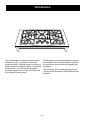
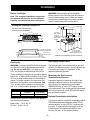
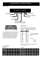
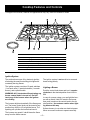
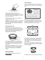
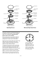
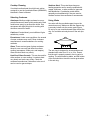
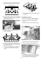
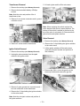
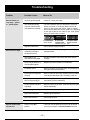
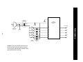
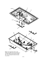
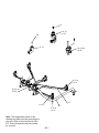
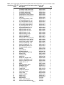
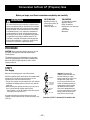
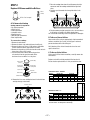
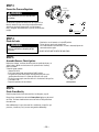
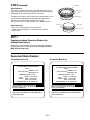
g
GE Consumer Home Services Training
TECHNICAL SERVICE GUIDE
36-In. Monogram
Stainless Steel Gas Cooktop
MODEL SERIES:
ZGU375NS
ZGU375LS
PUB # 31-9088
12/01
!
IMPORTANT SAFETY NOTICE
The information in this service guide is intended for use by
individuals possessing adequate backgrounds of electrical,
electronic, and mechanical experience. Any attempt to repair a
major appliance may result in personal injury and property
damage. The manufacturer or seller cannot be responsible for the
interpretation of this information, nor can it assume any liability in
connection with its use.
WARNING
If the information in this manual is not followed exactly, a fire or explosion may result causing property damage, personal injury or death.
If you smell gas:
- Do not try to light any appliance.
- Do not touch any electrical switch; do not use any phone in
the building.
- Immediately call the gas supplier from a neighbor’s phone.
Follow the gas supplier’s instructions.
- If you cannot reach the gas supplier, call the fire department.
WARNING
To avoid personal injury, disconnect power before servicing this product. If electrical power is required for diagnosis or test
purposes, disconnect the power immediately after performing the
necessary checks.
RECONNECT ALL GROUNDING DEVICES
If grounding wires, screws, straps, clips, nuts, or washers used to
complete a path to ground are removed for service, they must
be returned to their original position and properly fastened.
GE Consumer Home Services Training
Technical Service Guide
Copyright © 2001
All rights reserved. This service guide may not be reproduced in whole or in
part in any form without written permission from the General Electric Company.
Table
of Contents
Table
of Contents
Introduction . . . . . . . . . . . . . . . . . . . . . . . . . . . . . . . . . . . . . . . . . . . . . . . . . . . . . 2
Installation . . . . . . . . . . . . . . . . . . . . . . . . . . . . . . . . . . . . . . . . . . . . . . . . . . . . . . 3
Specifications and Nomenclature5 . . . . . . . . . . . . . . . . . . . . . . . . . . . . . . . . . . 4
Warranty Information . . . . . . . . . . . . . . . . . . . . . . . . . . . . . . . . . . . . . . . . . . . . . . 5
Cooktop Features and Controls . . . . . . . . . . . . . . . . . . . . . . . . . . . . . . . . . . . . 6
Mechanical Disassembly . . . . . . . . . . . . . . . . . . . . . . . . . . . . . . . . . . . . . . . . . 10
Troubleshooting . . . . . . . . . . . . . . . . . . . . . . . . . . . . . . . . . . . . . . . . . . . . . . . . 16
Component and Connector Locator Views . . . . . . . . . . . . . . . . . . . . . . . . . . 18
Wiring Diagram . . . . . . . . . . . . . . . . . . . . . . . . . . . . . . . . . . . . . . . . . . . . . . . . . 20
Schematics . . . . . . . . . . . . . . . . . . . . . . . . . . . . . . . . . . . . . . . . . . . . . . . . . . . . 21
Parts List . . . . . . . . . . . . . . . . . . . . . . . . . . . . . . . . . . . . . . . . . . . . . . . . . . . . . . 22
Conversion to/from LP (Propane) Gas . . . . . . . . . . . . . . . . . . . . . . . . . . . . . . 26
[[Title]]
–1–
Introduction
The new Monogram cooktop makes an eloquent
statement of style, convenience, and kitchen
planning flexibility. Whether chosen for its purity of
design, assiduous attention to detail—or for both of
these reasons—you’ll find that the Monogram
cooktop’s superior blend of form and function will
be a delight for years to come.
This Monogram cooktop was designed to provide
the flexibility to blend in with any kitchen cabinetry.
Its sleek design can be beautifully integrated into
the kitchen.
The information on the following pages will help
you service this Monogram cooktop efficiently and
effectively.
–2–
Installation
WARNING: Before beginning the installation,
switch power off at the service panel and lock the
service disconnecting means. When the service
disconnecting means cannot be locked, securely
fasten a warning tag to the service panel.
Before You Begin...
Note: The complete installation instructions
are inclosed with the Use and Care Manual.
Carefully read and follow these instructions.
Monogram Cooktop Dimensions
13"
Max.
Dimensions for reference only
Unit shown fully assembled
2-3/4" Min.
From Cooktop
to Vertical
Combustible
Surface When
Installed
36-1/2"
20-5/8"
Deep
at Center
19-3/4"
2-3/4
From
to Ve
Comb
Surfa
Insta Cutout
stibles
5-1/2"
30"
36" Min. 18" Min. Min.
See Note
n. to
3-3/8" Min. From Cutout utout
to Vertical Combustibles
18-7/8"
7" Min. to Wall
From Cooktop Edge
When Installed Both Sides
7-9/16" Min. to
Wall From Cutout
35-5/16"
Note: Refer to hood installation instructions for dimension.
2-3/4" Min.
Gas Supply
Gas Supply Shutoff Valve
WARNING: Cooktop model ZGU375NS is shipped
from the factory set to operate only with natural
gas. Do not use with LPG. If you wish to use
LPG, you must have cooktop model ZGU375LS.
The cooktop itself is not equipped with a gas shutoff valve. If installed correctly, a shutoff valve will be
in the main gas supply line “upstream” of the
appliance pressure regulator.
These cooktops are designed to operate on natural
gas at 4 in. of water column pressure or on LP gas
at 10 in. of water column pressure, depending on
model. For proper operation, the maximum inlet
pressure to the regulator must be no more than
10 in. of water column pressure for natural gas
and 14 in. of water column pressure for LP gas.
GAS SUPPLY REQUIREMENTS
Gas Type
Incoming Pressure
to Regulator
Pressure Regulator
Output Supplies
Natural
LP
6.0" to 9.0" W.C.P.
11" to 14" W.C.P.
4.0" W.C.P.
10.0" W.C.P.
Recommended minimum regulator input pressure
to maximize performance:
Natural Gas – 7.0-in. W.C.P.
LP Gas – 12.0-in. W.C.P.
Measuring the Gas Pressure
Supplied to the Burners
A pressure tap hole is located on the side of the
regulator to allow checking of the manifold pressure. Remove the regulator plug and install a
WB02X10820 tap (or 1/8 in. NPT nipple) for test
with a manometer. Turn on the gas and light at least
one burner to serve as a load. Reinstall the regular
plug and check for leaks.
Optional Combination Installations
This cooktop may be installed in combination with a
ZVB36 Monogram downdraft vent, with a ZTD30
warming drawer, or with a ZET837 single convection oven. The gas and electrical supply must be
located where it will not interfere with the vent
housing, the oven, or the warming drawer.
–3–
Specifications and Nomenclature
Model Number
Z G U 3 7 5 N S
Monogram
Stainless Steel
Type of Gas to Be Used
N = Natural
L = LPG
GAS
Cooktop
Feature Pack
Designates features–the higher
the number, the more features.
Serial Number
The first two characters of the serial number
identify the month and year of manufacture.
Example:
AA123456S = January, 2001
A - JAN
D - FEB
F - MAR
G - APR
H - MAY
L - JUN
M - JUL
R - AUG
S - SEP
T - OCT
V - NOV
Z - DEC
The serial plate of your cooktop is located on
the bottom of the burner box. In addition to
the model and serial numbers, it tells you the
ratings of the burners and the type of fuel
and pressure the cooktop was adjusted for
when it left the factory. Also included are
minimum wall clearance requirements.
2005 - H
2004 - G
2003 - F
2002 - D
2001 - A
2000 - Z
1999 - V
1998 - T
1997 - S
1996 - R
1995 - M
1994 - L
The letter designating the
year repeats every 12
years.
Example:
T - 1974
T - 1986
T - 1998
Note: The technical sheet is located under the
control panel.
Orifice/Jet DMS
LP Gas
Natural Gas
Natural @ 4"
Rate, HI
Rate,LOW
Rate,SIM
Main Orifice
Sim. Orifice
Valve Jet
Main Or. Color
Sim. Or. Code
LF
LR
RR
10.5K
12K
12K
2.5K
2.5K
2.5K
1.2K
1.2K
1.2K
1.45mm 1.59 mm 1.59 mm
0.57 mm 0.57 mm 0.57 mm
0.71 mm 0.71 mm 0.71 mm
Orange
Red
Red
P
P
P
RF
C
10.5K
15K
2.5K
3.4K
1.2K
1.2K
1.45mm 1.78 mm
0.57 mm 0.51 mm
0.71 mm 0.71 mm
Orange Yellow
P
V
LP @ 10"
Rate, HI
Rate,LOW
Rate,SIM
Main Orifice
Sim. Orifice
Valve Jet
Main Or. Color
Sim. Or. Code
–4–
LF
LR
RR
RF
C
8.5K
8.5K
8.5K
8.5K
15K
2.3K
2.3K
2.3K
2.3K
2.4K
1.1K
1.1K
1.1K
1.1K
1.1K
0.81 mm 0.81 mm 0.81 mm 0.81 mm 1.10 mm
0.34 mm 0.34 mm 0.34 mm 0.34 mm 0.37 mm
0.46 mm 0.46 mm 0.46 mm 0.46 mm 0.46 mm
White
White
White
White
Black
E
E
E
E
G
Warranty Information
Sales slip or cancelled check is required as proof of original purchase date to
obtain service under warranty.
All warranty service is provided by our Factory Service Centers or an authorized
Customer Care® technician.
What is
Covered
FULL ONE-YEAR WARRANTY
For one year from date of original purchase, we will provide, free of charge, parts and
service labor in your home to repair or replace any part of the cooktop that fails because
of a manufacturing defect.
This warranty is extended to the original purchaser and any succeeding owner for products
purchased for ordinary home use in the 48 mainland states, Hawaii and Washington, D.C.
In Alaska the warranty is the same except that it is LIMITED because you must pay to ship
the product to the service shop or for the service technician’s travel costs to your home.
All warranty service will be provided by our Factory Service Centers or by our authorized
Customer Care® servicers during normal working hours.
Should your appliance need service, during warranty period or beyond, call 800-444-1845.
What is
Not
Covered
• Service trips to your home to teach you how
to use the product.
• Replacement of house fuses or resetting of
circuit breakers.
• Damage to the product caused by accident,
fire, floods or acts of God.
• Failure of the product if it is used for other
than its intended purpose or used
commercially.
• Improper installation.
If you have an installation problem, contact
your dealer or installer. You are responsible
for providing adequate electrical, gas,
exhausting and other connecting facilities
as described in the Installation Instructions
provided with the product.
WARRANTOR IS NOT RESPONSIBLE
FOR CONSEQUENTIAL DAMAGES.
Some states do not allow the exclusion or limitation of incidental or consequential damages,
so the above limitation or exclusion may not apply to you. This warranty gives you specific legal
rights, and you may also have other rights which vary from state to state.
To know what your legal rights are in your state, consult your local or state consumer affairs
office or your state’s Attorney General.
Warrantor: General Electric Company, Louisville, KY 40225
–5–
Cooktop Features and Controls
Throughout this manual, features and appearances may vary from the customer’s model.
Design
information
2
5
1
1
(Not all features
are on all models.
Appearance may vary.)
1
6
3
4
1
6
Feature Index
1
Dual-Flame Spillproof Burners—High Output
2
Dual-Flame Spillproof Burner—Maximum Output
3
Tactile-touch Control Knobs (One for Each Surface Burner)
4
Burner “ON” Indicator Lamps (One on Each Control Knob)
5
Interlocking Grates
6
Wok Ring Accessory
Ignition System
The surface burners are lit by electronic ignition,
eliminating the need for standing pilot lights with
constantly burning flames.
The ignition system is not sensitive to reversed
house wiring polarity.
The ignition system consists of 5 spark switches
(1 on each valve), 5 spark electrodes (1 on each
burner), and a spark module.
Lighting a Burner
WARNING: All 5 electrodes will spark when any
burner control knob is turned on. Do NOT
touch any of the burners when the igniters
are clicking.
The burners relight automatically if the flame goes
out. The burner control knob can be turned to any
position from HIGH to LO to light the burner. The
sparking will quit after the burner has been lit.
The burners may spark if a draft blows the flame
away from the burner sensor.
Push the control knob down and turn it counterclockwise to the desired position from HIGH to
SIM.
In case of a power outage, you can light the burners with a match. Hold a lit match to the burner,
then push in and turn the control knob to the desired position. Use extreme caution when lighting burners this way.
Surface burners in use when an electrical power
failure occurs will continue to operate normally.
–6–
Burner Cleaning
The slits in the burner rings of the cooktop must
be kept clean at all times for an even, unhampered
flame.
Electrode
The electrode of
the spark igniter is
behind each burner.
When one burner is
turned to “ON” to
light, all the burners
spark. Do not attempt to disassemble or clean
around any burner while another burner is
on. An electric shock may result, which could
cause you to knock over hot cookware.
Check to be sure the burner you turned on is
the one you want to use.
After the burner lights, turn the knob in
eitherdirection to adjust the flame size. To turn a
burner off, turn the knob clockwise as far as it will
go, to the OFF position.
The indicator lamp in the bezel for each knob
verifies the burner is ON.
Caution: Do not operate a burner for an extended
period of time without cookware on the grate. The
finish on the grate may chip without cookware to
absorb the heat.
Note: Before removing the burner caps and
burner ring subassemblies, remember their size
and location. Replace them in the same location
after cleaning for proper burner operation.
Maximum
Output
Selecting Flame Size
All 5 burners on your cooktop have 2 rows of
flames. These dual-flame burners have an upper
ring of main burner ports which produce the main
flame for high-heat cooking from the HI knob
setting to the LO knob setting.
High
Output
High
Output
High
Output
High
Output
Front of Cooktop
Main Flame
Simmer Flame
The bottom simmer flame is used for simmer
heat cooking operations such as melting chocolate, holding food at serving temperature, and
simmering.
To completely clean the burner ring subassembly
remove the burner cap, head, and the 1-1/16 in.
nut. Lift off the burner ring. Do not remove the
burner bases.
Make sure the small holes in the simmer rings are
kept open. A sewing needle or wire twist-tie works
well to unclog them.
Both MAIN and SIMMER flames are lit when the
knob is between HI and LO. Only the simmer
flame is lit when the knob is in the SIMMER
position.
Slits
Burner Adjustment
There is no adjustment on this burner. See
Burner Cleaning.
Holes
To remove burned-on food, soak the burner heads
–7–
Burner Cap
Burner Cap
Burner Head
(Brass)
Burner Head
(Brass)
Burner Ring
Locking Nut
Locator Pin
Burner Ring
Locking Nut
Locator Pin
Burner Ring
(Aluminum)
Burner Ring
(Aluminum)
Electrode
Locator Pin
Electrode
Locator Pin
Burner Base
Burner Base
Pin
Slot
Pin
Slot
NOTE: Locator pin fits
into burner base pin slot.
NOTE: Locator pin fits
into burner base pin slot.
High- Output Burners
Maximum- Output Center Burner
and rings in a solution of mild liquid detergent and
hot water for 20-30 minutes. For more stubborn
stains, use a toothbrush. Clean the burner
bases in place on the cooktop.
Before putting the burner parts back, shake out
excess water and then dry them thoroughly by
setting them in a warm oven for 30 minutes.
Replace the burner parts. Make sure that the rings,
heads, and caps are replaced in the correct
location. There are four medium sets and one
large set of rings, heads, and caps.
To replace the burner parts, make sure all parts
are for the correct burner, in the correct location,
and firmly seated. Align the locator pin on the
burner ring into the labeled hole in the burner base.
Replace the burner ring locking nut and handtighten. Turn the nut 1/4 turn to secure it in place.
Align the locator pin in the burner head into the
hole in the burner ring. Replace the burner cap.
–8–
To aid reassembly, each
brass Burner Head is
marked with a clock face.
Replace the Burner Head
with the arrow pointing
to the rear of the cooktop
(12 o’clock position).
Cooktop Cleaning
If cooktop has discolored from high heat, advise
customer to use the furnished cleaner (WB64X93)
identified in Owner’s Manual.
Stainless Steel: This metal alone has poor
heating properties and is usually combined with
copper, aluminum, or other metals for improved
heat distribution. Combination metal skillets
generally work satisfactorily if they are used at
medium heat as the manufacturer recommends.
Selecting Cookware
Aluminum: Medium-weight cookware is recommended because it heats quickly and evenly. Most
foods brown evenly in an aluminum skillet. Use
saucepans with tight-fitting lids for cooking with
minimum amounts of water.
Cast Iron: If heated slowly, most skillets will give
satisfactory results.
Using Woks
Use woks with the provided support ring on the
center burner only. Make sure that the support ring
is securely locked onto the center grate fingers.
Do not try to use round-bottomed woks without the
ring. You could be seriously burned if the wok tips
over.
Enamelware: Under some conditions, the enamel
of some cookware may melt. Follow cookware
manufacturer’s recommendations for cooking
methods.
Glass: There are two types of glass cookware:
those for oven use only and those for surface
cooking (saucepans, coffee pots, and teapots).
Glass conducts heat very slowly.
Heat-Proof Glass Ceramic: This can be used for
either surface or oven cooking. It conducts heat
very slowly and cools very slowly. Check the
cookware manufacturer’s directions to be sure it
can be used on gas cooktops.
The wok ring is designed to accommodate most
standard size woks from 12 in. to 18 in. Ensure
that the wok is properly nested in the ring prior to
cooking. The wok should be stable, and the bottom
of the wok should not touch the center grate when
in the wok ring.
–9–
Mechanical Disassembly
Table of Contents
Maintop Removal . . . . . . . . . . . . . . . . . . . . . . . . . . . . . . . . . . . . . . . . . . . . . . . . . 11
Spark Module Removal . . . . . . . . . . . . . . . . . . . . . . . . . . . . . . . . . . . . . . . . . . . . 12
Transformer Removal . . . . . . . . . . . . . . . . . . . . . . . . . . . . . . . . . . . . . . . . . . . . . . 13
Igniter Switch Removal . . . . . . . . . . . . . . . . . . . . . . . . . . . . . . . . . . . . . . . . . . . . 13
Valve Removal . . . . . . . . . . . . . . . . . . . . . . . . . . . . . . . . . . . . . . . . . . . . . . . . . . . . 13
Manifold Removal . . . . . . . . . . . . . . . . . . . . . . . . . . . . . . . . . . . . . . . . . . . . . . . . . 14
Simmer Jet Holder Removal . . . . . . . . . . . . . . . . . . . . . . . . . . . . . . . . . . . . . . . . 14
Main Jet Holder Removal . . . . . . . . . . . . . . . . . . . . . . . . . . . . . . . . . . . . . . . . . . . 15
Burner Light Removal . . . . . . . . . . . . . . . . . . . . . . . . . . . . . . . . . . . . . . . . . . . . . 15
Center Brace Removal . . . . . . . . . . . . . . . . . . . . . . . . . . . . . . . . . . . . . . . . . . . . . 15
End Brace Removal . . . . . . . . . . . . . . . . . . . . . . . . . . . . . . . . . . . . . . . . . . . . . . . 15
– 10 –
WARNING: Disconnect electrical power to the
cooktop and turn OFF gas at the main valve before
performing any removal procedures.
Note: The cooktop itself is not equipped with a gas
shutoff valve. If installed correctly, a shutoff valve
will be in the main gas supply line “upstream” of
the appliance pressure regulator.
Caution: When removing the wire from the igniter,
make sure you do not damage the heat shrink
insulation on the wire. If damaged, repair the wire
insulation with fiberglass tape.
5. Lift each burner base and disconnect the pushon wire terminal from the spark electrode.
Place the burner base assemblies in a safe
place.
Note: When assembling, check the integrity of the
heat shrink on the igniter leads going to the
electrodes. If damaged, proper ignition may not
occur. Repair the wire insulation with fiberglass
tape.
Maintop Removal
Note: Maintop removal is required for:
• Spark module
• Gas piping inspection
• Wiring service
• Valve replacement
• Jet holder service
• Manifold service
• Indicator light replacement
• Bezel replacement
• Isolation transformer
1. Remove the valve knobs.
2. Remove the burner caps and burner head
assemblies.
3. Remove the 1-1/16 in. burner ring locking nut.
4. Remove the large brass orifice tube from the
center of each burner base using a 20-mm or a
13/16-in. socket.
Burner Cap
Burner Cap
Burner Head
(Brass)
Burner Head
(Brass)
Burner Ring
Locking Nut
Locator Pin
Burner Ring
(Aluminum)
Electrode
Locator Pin
To aid reassembly, each
brass Burner Head is
marked with a clock face.
Replace the Burner Head
with the arrow pointing
to the rear of the cooktop
(12 o’clock position).
Burner Ring
Locking Nut
Locator Pin
Burner Ring
(Aluminum)
Electrode
Locator Pin
Burner Base
Burner Base
Pin
Slot
Pin
Slot
NOTE: Locator pin fits
into burner base pin slot.
NOTE: Locator pin fits
into burner base pin slot.
High - Output Burners
Maximum- Output Center Burner
– 11 –
6. Remove the left screws holding the bezels for
the left-front and right-front gas valve knobs.
Heat
Shield
Remove Screws
11. To reinstall the maintop, reverse the procedure
1 through 10.
7. Raise the maintop front about 6 in. and disconnect the 6-pin connector under the maintop and
behind the right-front valve.
Spark Module Removal
1. Remove the maintop (see Maintop Removal).
2. Remove the heat shield held by 4 Phillips
screws.
3. Unplug the connector from the spark module.
8. Push the spark electrode wires through the
holes in the maintop.
4. Unplug 5 igniter wires from the spark module.
9. Pick the maintop straight up and place face up
in a safe area where it will not be scratched or
accidently knocked over.
5. Remove 2 screws and the spark module.
10. To service the spark module or transformer,
remove the heat shield held by 4 Phillips
screws.
6. To reinstall the spark module, ensure the connector is properly seated and the igniter wires
are connected in their original positions.
– 12 –
Transformer Removal
5. Lift each igniter switch off the valve stem.
1. Remove the maintop (see Maintop Removal).
2. Remove the heat shield held by 4 Phillips
screws.
Note: Note the color and position of the 4
transformer wires.
3. Remove 3 wire screw connectors and 1 ground
connector screw.
Note: When replacing the switch, replace the
entire harness with colors in same positions. The
bottom of the switch is molded to conform to the
top of the valve for a locked-in fit. Reconnect both
ground wires and replace wire ties.
Valve Removal
1. Remove the maintop (see Maintop Removal).
4. Remove 2 screws and the transformer.
2. Remove the C-clips holding the igniter switches
to the valve stems.
Igniter Switch Removal
3. Lift the igniter switches off the valve stems.
(Note the color/part number and positions of
the switches.)
1. Remove the maintop (see Maintop Removal).
2. Unplug the wire connector from the spark
module to the igniter switch.
4. Remove the 3/8-in. nut on the gas line to the
simmer jet holder and remove the gas line.
3. Remove 2 green ground wire connectors and 1
wire nut connection to the transformer.
4. Remove the C-clips holding the igniter switches
to the valve stems.
Note: Note the color/part number and position of
the igniter switches.
– 13 –
6. From under the counter, remove 2 screws at
the manifold.
5. Remove the 9/16-in. nut on the gas line to the
main jet holder and remove the gas line.
7. Remove two 7/16-in. screws and the manifold.
6. Remove two 5/16-in. nuts and the valve.
7. To reinstall the valve, make sure the valve is
seated on the manifold and the valve stem is
vertical.
Simmer Jet Holder Removal
1. Remove the maintop (see Maintop Removal).
2. Remove the 5/16-in. nut on the gas line.
Manifold Removal
1. Remove the maintop (see Maintop Removal).
2. Remove the C-clips holding the igniter switches
to the valve stems.
3. Lift the igniter switches off the valve stems.
(Note the color and positions of the switches.)
3. Remove the 5/8-in. nut on the jet holder and
remove the jet holder.
4. Remove the valves (see Valve Removal).
5. Remove the gas fitting located under the
counter from the manifold.
– 14 –
Main Jet Holder Removal
Center Brace Removal
1. Remove the maintop (see Maintop Removal).
1. Remove the maintop (see Maintop Removal).
2. Remove the 9/16-in. nut on the gas line.
2. Remove the simmer jet holders (see Simmer
Jet Holder Removal).
3. Remove the main jet holders (see Main Jet
Holder Removal).
4. Remove the heat shield held by 4 Phillips
screws.
5. Remove 3 screws and the center brace.
End Brace Removal
1. Remove the maintop (see Maintop Removal).
2. Remove the simmer jet holders (see Simmer
Jet Holder Removal).
3. Remove the 5/8-in. nut on the jet holder and
remove the jet holder.
3. Remove the main jet holders (see Main Jet
Holder Removal).
4. Remove the heat shield held by 4 Phillips
screws (if removing the right end brace).
5. Remove the screws to the center brace.
6. Remove 2 holddown brackets from under the
countertop, lift the burner box from the counter,
turn it 10 degrees, and insert cardboard or
wood under the burner box to protect the
countertop.
7. Remove the 4 brace screws from the exterior
of the burner box and remove the brace.
Burner Light Removal
1. Remove the maintop (see Maintop Removal).
2. Turn the top face down on a protected surface.
3. Disconnect the 2 blade connections.
4. Slide the light housing unit in the direction of the
connector blades to remove.
– 15 –
Troubleshooting
Problem
Possible Causes
What to Do
Burner flames are
very large, yellow,
or yellow-tipped
Incorrect gas being used.
• Check for correct gas supply
The combustion quality
of burner flames needs
to be determined visually.
• Use the illustrations below to determine if the burner
flames are normal. If the burner flames look like A,
check for dirty burners and orifices. Clean or replace.
Normal burner flames should look like B or C, depending
on the type of gas you use. With LP gas, some yellow
tipping on outer cones is normal.
A–Yellow flames
Call for service
Burners do not light
Burner control knob
will not turn
B–Yellow tips
C–Soft blue flames
on outer cones
Normal for natural
Normal for LP gas gas
Regulator malfunction.
• Check output gas supply (see page 3).
Plug on cooktop is not
completely inserted in
the electrical outlet.
• Make sure electrical plug is plugged into a live, properly
grounded outlet.
Gas supply is not
connected or turned ON.
• See the Installation Instructions that came with the
cooktop.
A fuse may be blown or a
circuit breaker tripped.
• Replace the fuse or reset the circuit breaker.
Insufficient Airflow
• Make sure rubber discs below knobs are pushed down
through bezel to valve assembly.
Burner parts not replaced
correctly.
• Make sure pins in the burner head are properly located
in the burner base holes. (See “Clocking”, page 14.)
Holes in simmer rings or
slits in burners clogged.
• Clean or replace as necessary. Make sure all components are dry before reassembly.
Liquid in burner base due
to spillage.
• Remove burner ring to check. Clean and dry thoroughly
before reassembly.
Orifices plugged or dirty.
• Clean or replace as necessary.
Igniter switch defective.
• Replace igniter switches.
Igniter wire defective.
• Connect igniter wire.
Spark module defective.
• Replace spark module.
Knob is in the OFF
position.
• The knob must be pushed in before it can be turned, it
can only be turned in a counterclockwise direction.
– 16 –
Problem
Possible Causes
What to Do
Ticking sound of
spark igniter persists
after burner lights
Improper flame sensing.
• Check igniter wiring.
• Replace the igniter.
Ticking sound
persists after burner
is turned OFF
Be sure the knob is in
the OFF position.
• Remove knob and check the bottom of knob for buildup
of soil. If ticking persists, replace igniter switches.
Defective igniter switch.
• Replace the igniter switch.
Simmer ring not seated
properly to base.
• Ensure the simmer ring is properly seated to base and
1-1/16 in. nut is fully seated and tight (1/4 turn after
contact).
Flame “Popping”
– 17 –
Component and Connector Locator Views
Note: Also see Parts List for additional components.
Transformer
Spark
Module
Heat Shield
Brace
(Remove to access
Spark Module &
Transformer)
Igniter Switch
Brace
Valve
Burner
Lights
(on under
side of top)
– 18 –
Manifold
Igniter
Wire
6-Pin Plug
Notes
– 19 –
Wiring Diagram
CONNECTOR
POWER CORD
WN #2
GRN
BLK
N 2
13
BLK
BLK
5 POINT
GAS RE-IGNITER
MODULE
230V
GRN
13
G 1
GRN
WN #3
WHT
6
120V
SPARK ELECTRODES
ON BURNERS
26
120/230V
TRANSFORMER
RR
17
LR
15
LF
14
OR
OR
OR
5
(RR) SW5 7
4
(LR) SW4 8
3
(LF) SW3 9
7
230V
WHT
WHT
25
11
WN #1
10
24
1
RF
18
C
16
OR
OR
2
(RF) SW2 10
9
1
(C) SW1 11
8
GRN
19
23
7
11
4
2
LR VALVE SW.
2
1
5
CENTER VALVE SW.
LF VALVE SW.
22
19
23
37
2
1
3
5
4
6
2
1
3
5
4
6
31
29
27
30
28
32
9
8
22
20
RR VALVE SW.
3
4
21
20
RF VALVE SW.
21
10
RR LIGHT
LR LIGHT
30
28
33
35
CENTER LIGHT
LF LIGHT
34
29
36
RF LIGHT
31
32
27
33
35
ALL OTHERS-BLACK
– 20 –
PI
JI
120/230V
TRANSFORMER
120V
5 POINT
GAS RE-IGNITER
MODULE
230V
ELECTRODES
RR
SW5
5
RR
SW4
4
LR
SW3
3
LF
SW2
2
RF
SW1
1
C
LR
– 21 –
LF
RF
C
VALVE
SWITCHES
Caution: Label all wires prior to disconnection
when servicing the controls. Wiring errors can
cause improper and dangerous operation. Verify
proper operation after servicing.
INDICATOR
LIGHTS
Schematics
POWER CORD
120 VAC IN
Parts List
52
51
53
5
1
6
2
999
34
3
7
4
30
40
31
32
Note: The components shown in this
drawing may differ from the components in
your unit. Refer to the microfiche or GEA
IPC for the component and part number
for your unit.
– 22 –
41
Screw
46
47, 50
43
38
43
39
28
29
43
44
Note: The components shown in this
drawing may differ from the components in
your unit. Refer to the microfiche or GEA
IPC for the component and part number
for your unit.
35
– 23 –
15
8, 9, 10,
13, 14
20
11, 12
22, 23, 24,
25, 26
8, 9, 10,
13, 14
22, 23, 24,
25, 26
37
11, 12
36
8, 9, 10,
13, 14
Note: The components shown in this
drawing may differ from the components in
your unit. Refer to the microfiche or GEA
IPC for the component and part number
for your unit.
– 24 –
Note: The components listed below may differ from the components in your unit. Refer to the
microfiche or GEA IPC for the component and part number for your unit.
Views
Description
Part No.
1
2
3
4
5
6
7
8
9
10
11
12
13
14
15
15
15
15
15
20
20
22
23
24
25
26
26
28
29
30
31
32
33
34
35
36
37
38
39
40
41
42
43
44
45
46
47
50
51
52
53
999
999
999
C SIMMER/ PORT RING ASSY
D SIMMER/ PORT RING ASSY
C BURNER BASE ASSY
D BURNERS BASE ASSY
C BURNER CAP, MATTE BLAC
D BURNER CAP, MATTE BLAC
VENTURI
JET HOLDER, MAIN,C,10.5K
JET HOLDER, MAIN, C, 12K
JET HOLDER, MAIN, C,9.9K
JET HOLDER, SIM,C&D,NAT
JET HOLDER, SIM,C&D,NAT
JET HOLDER, MAIN, D, 15K
JET HOLDER,MAIN,D,11.7K
ORIFICE-MAIN, NAT 15K
ORIFICE-MAIN, NAT 12K
ORIFICE-MAIN, NAT 10.5K
ORIFICE-MAIN, LP 11K
ORIFICE-MAIN, LP 9.9K
ORIFICE-SIMMER, NAT
ORIFICE-SIMMER, LP
VALVE,DUAL FLOW,C,NAT12O
VALVE,DUAL FLOW,C,NAT6O’
VALVE,DUAL FLOW,C,LP.12O
VALVE,DUAL FLOW,C,LP.6O’
VALVE BY-PASS NET - NAT
VALVE BY-PASS NET - LP
RE-IGNITER MODULE, 5 PT.
TRANSFORMER 120/230V
IGNITOR
CLIP, IGNITOR
ISPRING, IGNITOR
WIRE HARNESS, IGNITION
REGULATOR
POWER CORD
MANIFOLD
MANIFOLD TUBING - SET
SWITCH, IGNITER, @12 O’C
SWITCH, IGNITER, @ 6 O/C
KNOB, WITH CLIP
BEZEL
WIRE HARNESS, MAIN
HARNESS, LIGHTS
THUMB SCREW
FOAM TAPE
COOKTOP W/LOGO
PILOT LIGHT, 240V
LIGHT TUBE
GRATE, CENTER
GRATE, LEFT
GRATE, RIGHT
MINI MANUAL
USE & CARE MANUAL
INSTALLATION INSTRUCTION
WB32X10026
WB32X10027
WB28X10044
WB28X10045
WB32X10028
WB32X10029
WB38X10062
WB16X10013
WB16X10014
WB16X10015
WB16X10016
WB16X10017
WB16X10018
WB16X10019
WB21X10065
WB21X10066
WB21X10067
WB21X10068
WB21X10069
WB21X10070
WB21X10071
WB21X10057
WB21X10058
WB21X10059
WB21X10060
WB21X10072
WB21X10073
WB13X10012
WB27X10538
WB02X10794
WB03X10146
WB02X10795
WB18X10169
WB21X10064
WB18X10170
WB02X10796
WB28X10046
WB24X10091
WB24X10092
WB03X10147
WB07X10482
WB18X10171
WB18X10172
WB01X10153
WB01X10152
WB02X10797
WB25X10008
WB25X10009
WB49X10075
WB49X10071
WB49X10076
31-20786
49-80023
49-80024
– 25 –
Qty
4
1
4
1
4
1
5
2
2
4
5
5
1
1
1
2
2
4
1
5
5
3
2
3
2
5
5
1
1
5
5
5
1
1
1
1
1
3
2
5
5
1
1
2
10
1
5
5
1
1
1
1
1
1
Conversion to/from LP (Propane) Gas
Before you begin, read these instructions completely and carefully
WARNING
This conversion kit must be installed by a qualified service
agency in accordance with the manufacturer’s instructions
and all applicable codes and requirements of the authority
having jurisdiction. If the information in these instructions
is not followed exactly, a fire, explosion or production of
carbon monoxide may result, causing property damage,
personal injury or loss of life. The qualified service agency
is responsible for the proper installation of this kit. The
installation is not proper and complete until the operation
of the converted appliance is checked as specified in the
manufacturer’s instructions supplied with the kit.
TOOLS NEEDED
PARTS INCLUDED
Main Burner Orifice (5)
Simmer Burner Orifice (5)
Valve Orifice (5)
Conversion Sticker (1)
1/8" Flat-blade Screwdriver
Adjustable Wrench
Phillips Screwdriver
Ratchet with 1-1/16" Hex Deep
Socket
25/32" Socket
Manometer
PROCEDURE
CAUTION: Before proceeding with the conversion, shut off
gas supply to the appliance prior to disconnecting the
electrical power.
The following steps must be followed to ensure the proper
conversion of the Monogram Sealed Burner Cooktops from
Natural Gas (NAT) to Liquid Propane Gas (LP) or Liquid
Propane to Natural:
STEP 1
Gas Supply
Measure the incoming gas pressure to the regulator.
With the installation of this conversion kit, the cooktop should
operate on LP gas at 10" of water column pressure and
on natural gas at 4" of water column pressure.
• The pressure regulator must be connected in series with the
manifold of the cooktop and must remain in series with the
supply line.
• When checking the regulator, the inlet pressure must be at
least 1" greater than the regulator output setting.
– If the regulator is set for 10" of water column pressure, the
inlet pressure must be at least 11".
For proper operation, the maximum inlet pressure to the
regulator must be no more than 14" of water column pressure
for LP gas.
Regulator
Solid Piping
or Flexible
Connector
Shut-Off
Valve
Pipe Stub
Important: Disconnect the
cooktop and the individual shutoff valve from the gas supply
piping system during any pressure
testing of that system at test
pressures greater than 1/2 psig.
Isolate the cooktop from the gas
supply piping system by closing
the individual manual shutoff
valve to the cooktop during any
pressure testing of the gas supply
piping system at test pressures
equal to or less than 1/2 psig.
Connection: 1/2" N.P.T. - minimum 5/8" dia. metal flex line.
– 26 –
7. Raise the cooktop front about 6" and disconnect the 6 pin
connector under the cooktop and behind the right front
valve.
8. Push the spark electrode wire through the holes in the
cooktop.
STEP 2
Replace All Burner and Valve Orifices
Valve
Orifice
Orifice Size Stamped
A. To Remove the Cooktop
Cooktop removal is required for:
• Gas piping inspection
• Wiring service
• Valve replacement
• Jet holder service
• Manifold service
• Indicator light replacement
• Bezel replacement
9. Pick the cooktop straight up and place in a safe area where
it will not be scratched or accidently knocked over.
10. To install the countertop, reverse the procedure 1 through 9.
B. To Access Burner Orifices:
To remove the cooktop:
1. Remove the valve knobs.
2. Remove the burner caps and main burner head (brass).
3. Remove the brass nut using a 1-1/16" socket or adjustable
wrench and lift the burner ring from the assembly.
4. Remove the large brass orifice tube from the center of each
burner base using a 25/32" socket.
5. Lift each burner base and disconnect the push-on
wire terminal from the spark electrode. Place
the burner base assemblies in a safe place.
Using a small 1/8" flat-blade screwdriver, carefully remove the
valve orifices.
Replace each orifice with the marked orifice from the kit.
Ensure that the replaced orifice is firmly seated in the valve.
Burner Ring
Locking Nut
MAIN ORIFICE COLOR
Burner Ring
(Aluminum)
C. To Access Valve Orifices:
Locator Pin
Electrode
Main Orifice
Simmer Orifice
6. Remove the left screws holding the bezels for the left front
and right front gas valve knobs.
ORIFICE/JET SIZES – NATURAL
BURNER
NATURAL GAS
BTU RATES
MAIN
SIM
VALVE
HI
LO
(REAR)
1.59 mm 0.57 mm 0.71 mm 12k
2490
(FRONT) 1.45 mm 0.57 mm 0.71 mm 10.5k
2490
(CENTER) 1.78 mm 0.61 mm 0.71 mm 15k
3400
SIM
1200
1200
1200
Remove Screws
ORIFICE/JET SIZES – LP
BURNER
LP GAS
MAIN
SIM
(REAR)
0.81 mm 0.34 mm
(FRONT) 0.81 mm 0.34 mm
(CENTER) 1.1 mm 0.37 mm
VALVE
0.46 mm
0.46 mm
0.46 mm
HI
8.5k
8.5k
15k
BTU RATES
LO
2330
2330
2440
RED
“P”
ORANGE “P”
YELLOW “V”
MAIN ORIFICE COLOR
Burner Base
SIM
1100
1100
1100
SIMMER ORIFICE CODE*
Burner Head
(Brass)
Verify that the orifices in the kit match the chart sizes and
replace the orifices.
WHITE
WHITE
BLACK
SIMMER ORIFICE CODE*
Burner Cap
Unscrew the orifice using an appropriately sized conventional
socket or nut driver. Use a piece of sticky tape in socket to
prevent the loose orifice from falling out.
“E”
“E”
“G”
*Simmer orifices are all brass because they are too small to color.
*ID code “letters” are stamped on orifice body.
– 27 –
STEP 3
Convert the Pressure Regulator
Reverse
Plastic Plunger
WARNING
Do not remove the pressure regulator from
the cooktop.
LP
To convert the regulator from Natural Gas to LP gas or LP to
Natural, remove the cap screw using an adjustable wrench
and reverse the plastic plunger (make sure the plunger is
firmly “swapped” and seated in the cap screw, see illustration
to right).
NAT
NAT
LP
Cap Screw
STEP 4
Check for Leaks
WARNING
Check for leaks before attempting to light
the burners.
• Check to be sure all controls are in the OFF position.
• Turn on the gas supply at the shutoff valve.
• Use a leak detector at all connections. If a leak is detected, tighten the
connection and test again.
DO NOT USE A FLAME TO CHECK FOR GAS LEAKS.
STEP 5
Assemble Burners, Check Ignition
Replace the cooktop, reconnect the wiring and reassemble the burners as
shown in Step 2. Make sure that burners are replaced in the “clocking”
pattern as shown.
• Check for proper ignition:
– Connect Electrical.
– Push in one control knob and turn 90° to “HIGH” position.
– The igniter will spark and the burner will light; the igniter will cease
sparking when the burner is lit. (Note that all burners will spark.)
– The first test may require some time while air is flushed out of the gas line.
– Turn knob to “OFF”.
– Repeat the procedure for each burner.
STEP 6
Check Flame Quality
Check for proper burner flame characteristics (see diagrams page 4).
Burner flames should be blue and stable. Some yellow tipping may be normal
on LP Gas. The flame should not have excessive noise or lifting of the flame
from the burner.
Due to differences in gas characteristics and burner usage (i.e. gas
pressure, cleanliness, etc.), burners may perform differently.
– 28 –
Clocking Pattern
STEP 6 (continued)
Burner Cap
Burner Operation
Two flames are used on all five burners. These dual flame burners have an
upper ring of main burner ports which produce the main flame for high heat
cooking from the “HI” knob setting to the “LO” knob setting.
High to Low
Flame
Simmer Flame
The bottom simmer flame is used for simmer heat cooking operations such as
melting chocolate, holding food at serving temperature and simmering.
Both flames are lit when the knob is between “HI” and “LO”.
Only the simmer flame is lit when the knob is in the “SIMMER” position.
Simmer Ring
Burner Adjustment
• There is no air shutter adjustment, etc. on this burner.
• The only adjustment available is to clean the burners and clean or
replace orifices.
Simmer Flame
Main Burner Ports
STEP 7
Complete and adhere Conversion Sticker to the
Cooktop Bottom Surface
Complete the required information on the Conversion Sticker and adhere to
the bottom of the unit next to Rating Plate Sticker. The Conversion sticker
MUST reflect the change in fuel.
Conversion Sticker Samples
A. From Natural Gas to LP
B. From LP to Natural Gas
THIS CONVERSION RATING LABEL RELATES TO THE
FOLLOWING GENERAL ELECTRIC MODELS
ZGU375
SUPPLY PRESSURE -
THIS CONVERSION RATING LABEL RELATES TO THE
FOLLOWING GENERAL ELECTRIC MODELS
ZGU375
MINIMUM 11" W.C.
SUPPLY PRESSURE -
MAXIMUM 14" W.C.
MANIFOLD PRESSURE - 10" W.C.
MINIMUM 6" W.C.
MAXIMUM 9" W.C.
MANIFOLD PRESSURE - 4" W.C.
CENTER - 15,000 BTU/HR
INPUT
RATINGS FRONT - 10,500 BTU/HR
REAR - 12,000 BTU/HR
CENTER - 15,000 BTU/HR
INPUT
RATINGS FRONT - 8,500 BTU/HR
REAR - 8,500 BTU/HR
CONVERSION KIT CAT. No. WB49X10088
CONVERSION KIT CAT. No. WB49X10087
THIS APPLIANCE HAS BEEN CONVERTED ON
FROM NATURAL GAS TO L.P. GAS WITH CONVERSION
KIT CAT. No. WB49X10087
THIS APPLIANCE HAS BEEN CONVERTED ON
FROM L.P. GAS TO NATURAL GAS WITH CONVERSION
KIT CAT. No. WB49X10088
Name and address of qualified installer or service organization
Name and address of qualified installer or service organization
WHO ACCEPTS RESPONSIBILITY FOR THE CORRECTNESS
OF THE CONVERSION
WHO ACCEPTS RESPONSIBILITY FOR THE CORRECTNESS
OF THE CONVERSION
– 29 –
– 30 –