1
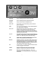
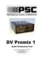
DV Promix 1
Audio Production Tool
Operation Manual for Mixers with PCB V1.3
Copyright 2008
Professional Sound Corporation
Printed in the U.S.A.
TABLE OF CONTENTS
DESCRIPTION……………………………………………………………………………3
SAFETY WARNINGS……………………………………………………………………4
APPLICATIONS…………………………………………………………………………..4
FRONT PANEL LAYOUT…………………………………………………………..…...5
REAR PANEL LAYOUT……………………………………………………..…………..6
FUNCTIONS
INPUTS……………………………………………………………………………7-8
A.
BALANCED INPUT
B.
INPUT LEVELS
C.
MICROPHONE POWERING
D.
LOW CUT FILTER
E.
CHANNEL GAIN
OUTPUTS…………………………………………………………………………..9
A.
BALANCED OUTPUT
B.
OUTPUT LIMITER
MONITOR………………………………………………………………………….9
A.
HEADPHONE MONITOR OUTPUT
MONITOR RETURN……………………………………………………………..9
A.
TAPE RETURN MONITOR GAIN
METER……………………………………………………………………………10
A.
PEAK READING METER
POWERING……………………………………………………………………….10
2
A.
INTERNAL POWER, ALKYLINE BATTERIES
B.
EXTERNAL POWER
CONSTRUCTION……………………………………………………………………11
A.
CHASSIS
B.
ELECTRONIC TOPOLOGY
C.
ENVIRONMENTAL OPERATION
INTERFACING……………………………………………………………………11-12
A.
TO DV CAMS
B.
TO CONSUMER CAMCORDERS
C.
TO WIRELESS MICROPHONES
WARRANTY AND NON-WARRANTY SERVICE…………………………………13
SPECIFICATIONS…………………………………………………………………….14
DECLARATION OF CONFORMITY……………………………...…………………15
DESCRIPTION
Thank you for purchasing the Professional Sound Corporation DV ProMix 1
Audio Production Tool. PSC is confident that this new DV ProMix 1 Audio
Production Tool has set new standards for portable audio production. Please
feel free to contact us if you have any comments or questions concerning your
new DV ProMix 1. Additionally, we invite you to share your suggestions for new
products you would like to see developed.
Professional Sound Corporation extends a six month warranty on parts and labor
to all DV Promix 1 Audio Production Tool owners who return their warranty cards
at the time of purchase. This warranty gives you specific rights, which are stated
on the card, and enables us to keep you informed of product updates.
The PSC DV Promix 1 Audio Production Tool provides all the functions
necessary to produce studio quality recordings in the field. It’s user friendly
features, rugged design and sonic purity make the DV Promix 1 perfect for DV
production, electronic news gathering (ENG) electronic field production (EFP).
3
HEARING SAFETY WARNINGS:
At Professional Sound Corporation, we care about your hearing both short
term and long term. With that in mind, please heed the following warnings:
Please be sure that you have read this entire manual before operating this
mixer.
While special attention has been given to your safety and hearing
protection, the operator determines proper and safe operating levels.
Please note the following:
Always turn down the headphone volume before plugging in your
headphones.
Always operate your headphones at the lowest practical level.
Be especially cautious in unknown or widely varying environments.
Remember, your ears are your livelihood. Turn it down!
APPLICATIONS
•
•
•
•
•
•
DV Field Production
Electronic News Gathering
Location Recording (Dialogue and Music)
Digital Recording
Broadcast Remotes
Desktop Mixing for Video Post Production
4
“MONITOR”
Pop up variable gain trim for monitor return amp.
“PRE-AMP”
Pop up variable gain trim for balanced main input.
“PHONES”
Pop up volume control for headphone level.
“BATT, EXT”
Power switch, up for internal battery, down for external
power or center off.
“PWR”
Two color LED indicating power. Green indicates batteries
O.K. Red indicates low batteries.
“80, 20, 150”
High pass filter used to reduce wind rumble, etc. Center
position is marked 20Hz and provides flat frequency
response. Up position rolls off frequencies below 80Hz for
moderate roll off, Down position rolls off frequencies below
150Hz for more severe roll off.
“IN, OUT”
These LEDs indicate when the input and output limiters are
activated. You can use the “IN” LED to set the pre-amp gain
and the “out” LED to help with the main fader setting.
“LIM”
Limiter switch. Up position activates the input and output
limiters. Down position turns off the limiters.
D/M, D, M
Headphone selections, Up position “D/M” sends the direct
signal (preamp input) to the left ear and sends the monitor
amp signal to the right ear. The center position “D” sends
the direct (preamp) signal to both ears. The down position
“M” sends the monitor signal to both ears.
“RC”
The “RC” LED is “on” when the optional boom pole remote
control is plugged in and activated.
“FADER”
Sets the overall level from the pre-amp to the output
amplifier. It’s effect can be easily seen on the meter.
“METER”
Multi-color six LED peak reading meter. -18 to -3 are
colored green, 0 is colored yellow and +3 is colored red for
ease of use.
5
“HEADPHONES”
Headphone jack. Can be used with headphones
from 25 to 600 ohms.
“BOOM REMOTE”
Connection for optional boom pole remote control.
It’s use allows the operator to set fader levels from
the boom pole.
“BALANCED MONITOT INPUT”
Electronically balanced monitor return input. It will
except signal levels from microphone level to line
level. This input is used for tape return or talk back
monitoring.
“12T, DYN, 48PH”
Microphone power switch. 12T position provides 12
volts AB mic power for 12T style microphones. DYN
position provides no microphone power and is for
use with dynamic microphones and line level signal
sources. The 48PH position provides 48 volts for
use with 48PH microphones.
“BALANCED MAIN INPUT”
Electronically balanced input for talent microphone.
Very low noise pre-amp capable of taking
microphone to line level signals.
“-40, -10, 0”
Balanced output signal level switch, -40dBv for
microphone level, -10dBv for consumer line level,
0dBv for professional line level devices.
“OUTPUT”
Transformer balanced output. See above for level
setting.
“EXT PWR”
External power jack. Center terminal positive.
Usable voltage range of 7 to 16Vdc.
6
INPUT:
A.
BALANCED INPUT
The PSC DV Promix 1 Audio Production Tool provides one input channel utilizing
a three pin female XLR connector. The studio grade input circuitry is
electronically balanced for improved RF rejection and in-field practicality. The
XLR connector is wired as follows: Pin 1 shield (ground), Pin 2 Audio high (in
phase), Pin 3 Audio low (out of phase). Balanced wiring enables longer cable
runs without the worry of excessive noise due to nearby electromagnetic and
radio frequency interference. These balanced inputs may be unbalanced if
desired. Either pin 2 or 3 may be tied to ground (pin 1) to unbalance the input of
the DV Promix 1.
B.
INPUT LEVELS
The PSC DV Promix 1 Audio Production Tool can accommodate a wide range in
input levels. Microphone levels of all types can be handled as well as line level
signals. The input range of the DV Promix 1 Audio Production Tool is –60dBu to
+4dBu. Thus the DV Promix 1 is compatible with all forms of consumer and
professional audio equipment. The input level trim pot is located on the front
panel of the DV ProMix 1. This pot is retractable for easy use. Simply press
lightly on the knob and the knob will pop out for easy adjustment. After setting
the pot to the proper level, simply press the knob down again and the pot will
retract and stay flush mounted to the panel. Turning the Pre-Amp gain trim
counter clock-wise lowers the gain of the first pre-amp. Turned fully counter
clock-wise, the DV ProMix 1 will accept line level signals. Turn the Pre-Amp gain
pot fully clock-wise, and the DV ProMix 1’s pre-amp is set for maximum gain.
This setting is normally used with dynamic microphones such as Shure SM58’s
tm, or Electro-Voice Re 50’s tm. Typical condenser microphones (powered
microphones such as 48PH mics) will require less gain than a dynamic
microphone and thus the pre-amp gain trim pot would normally be set
somewhere around the 2:00 or 3:00 position. This input level gain setting are
used to correctly interface sources of varying levels to the DV Promix 3’s
preamplifiers. Correct level matching ensures maximum headroom and lowest
possible noise floor. To correctly set the Pre-Amp gain trim pot, switch on the
limiter switch, pop out the Pre-Amp gain pot knob and slowly raise the gain pot
while operating the microphone with the expected audio source volume. (If you
are going to record a whisper, then set the gain while whispering, if you are going
to record a scream, then set the gain while screaming) As soon as the “Input”
limiter LED begins to light, back off the Pre-Amp gain trim pot a just a little until
the LED no longer lights. At this point, the Pre-Amp gain is properly set and you
can press the pot inward to get it out of your way.
C.
MICROPHONE POWERING
The DV Promix 1 Audio Production Tool can accommodate the most popular
microphones used today. The microphone powering switch is located directly
7
above the Pre-Amp input XLR connector. This swirtch can be switched to either
Dynamic (D), 48Phantom (48PH) or 12T microphone power.
In the Dynamic position the mixer provides no microphone powering. This
position is used with Dynamic Microphones, Line Level inputs and when using
Wireless Receivers.
In the 48 Phantom Position the mixer provides 48 volts DC to power 48PH
microphones or simplex powered microphones with a range of 9 to 52 volts. Pin
1 is shield to ground while pins 2 and 3 carry 48 volts DC. The term “phantom” is
derived from the fact that there is no voltage potential developed across a
dynamic microphone transducer that would interfere with its operation. However,
most portable wireless receivers will not operate properly with 48PH turned on.
We strongly recommend setting inputs to dynamic for use with all wireless
systems.
In the 12T setting, the DV ProMix 1 will provide 12T microphone powering for use
with microphones designed for this powering standard. This is an older standard
used primarily in the Motion Picture Audio (feature film) sound recording
business. Microphones designed for this type of powering are typically made by
the German Microphone makers such as Sennheiser or Scheops. The 12T
microphone power standard provides a 12 volt potential between pins 2 and 3
with pin 2 being positive with respect to pin 3.
Please note that 48PH must not be used with 12T microphones and vice-versa.
Always use the correct power for the microphone being used. Failure to do so
may damage the microphone and/or the DV ProMix 1.
D.
LOW CUT FILTER
The Pre-Amp input of the DV Promix 1 Audio Production Tool is equipped with a
low cut (high pass) filter. This filter is activated via the three way switch located
on the front panel. These filters will attenuate all frequencies below a preset
frequency at a rate of 6dB per octave. When set at “20Hz”, frequencies below 20
Hz are effectively rolled off with the mixer operating at full frequency response.
Optional low cut filter settings of 80Hz and 150Hz will roll off the frequencies
below these figures at a rate of 6dB per octave (-3dB level at 80Hz and 150Hz
respectively). Low cut filtering is important in location recording where wind
noise can cause pre-amplifier overload. This effect can be minimized by
switching the low cut filter setting to either an 80Hz or 150Hz cutoff. The low cut
filter switches are located on the front of the DV Promix 1.
E.
CHANNEL GAIN
The overall volume of the audio to be recorded is controlled by the main fader.
Rotating the fader clock-wise increases the audio level (signal volume). Rotating
the fader pot counter clock-wise lowers the audio level. Proper operating level is
determined by using the LED meter. (see meter section of this manual)
8
OUTPUT:
A.
BALANCED OUTPUT (XLR Male Connector)
The DV Promix 1 Audio Production Tool contains a very high quality transformer
balanced output. This transformer and the related drive circuitry has been
designed to provide wide bandwidth, low distortion and real-world ease of use.
This output is available via the rear panel mounted male XLR connector. This
output is switchable between Professional Line Level (0dBv), Consumer Line
Level (-10dBv) or Microphone Level (-40dBv).
B.
OUTPUT LIMITERS.
The limit threshold (activation level) is factory set at +3 on the meter. The limiters
compress the signal at approximately 2.7 to 1 ratio. This is to say an increase of
2.7dB in input signal will result in only a 1dB increase in output signal. Most video
cameras have limited audio track headroom and can easily be overloaded
resulting in distortion of the recorded audio. For this reason, the DV Promix 1
contains limiters that are controlled automatically for ease of use and high quality
recordings.
C.
HEADPHONE OUTPUT
The Headphone output is located on the rear panel of the mixer. The DV Promix
1 Audio Production Tool’s headphone amplifier circuitry is designed to drive
virtually any headphone with an impedance rating of 25 to 600 Ohms. The
headphone circuitry is controlled by the use of a switch and a volume control that
are conveniently located on the front panel. The switch is used to control what
the operator listens to. It allows the operator to chose between monitoring “D”
(Direct) audio that is present on the ProMix 1’s output or in the “M” (Monitor) the
headphones are fed with audio from the Monitor input. “Monitor” audio that may
be fed back from the headphone jack of the camera ensuring that audio has
been recorded. This “Monitor” function is commonly called tape confidence
monitoring. In the D/M position, your left ear will hear “Direct” audio and your
right ear will hear “Monitor” audio
*SAFETY NOTE* ALWAYS TURN DOWN THE HEADPHONE VOLUME
BEFORE PLUGGING IN YOUR HEADPHONES.
D.
MONITOR INPUT
The DV Promix 1 Audio production Tool is equipped with a 3 pin female XLR jack
for use in monitoring talk back signals as well as tape confidence signals. These
levels are adjusted using the re-tractable trim pot on the front panel of the DV
ProMix 1.
9
METERS:
A.
PEAK READING METER
The DV Promix 1 Audio Production Tool is equipped with an LED meter. We
designed this meter to be easy to read and camera emulating. Because the
most common use of this type of mixer is with DV Cams, we designed the DV
Promix 1’s meter to emulate the peak reading attributes found on many DV
Cams. In this manor, you can be confident of your recording levels even when
the DV Cam is being fed via cable or wireless transmission. The LED’s used on
the DV ProMix 1’s meter are color coded for easy use. For signals up to –3dBv,
the LED’s are GREEN in color. The 0dBv LED is AMBER in color and signals of
+3dBv and above are shown as RED. In this manner, you need not concentrate
on the panel markings, just note the colors. Always have some Green LEDs on,
Occasionally have the Amber LED flashing, and try and keep the red LED off as
much as possible. By monitoring your audio signal level and riding the main
fader to adjust the levels as mentioned above, you will be assured of high quality
audio.
POWERING:
A. INTERNAL POWER, ALKALINE BATTERIES
Two “9 Volt” alkaline batteries can used to power the DV Promix 1 Audio
Production Tool.
These batteries are housed in a convenient battery
compartment located on the side panel of the mixer. When using alkaline
batteries, you can expect 4 to 6 hours of operation under normal circumstances.
Note: Never store your DV Promix 1 Audio Production Tool for extended
periods of time with alkaline batteries installed in the mixer. There is a
possibility that the batteries may leak causing corrosion of the mixer.
Battery leakage and the resulting corrosion damage is not covered under
the DV Promix 1 warranty.
B. EXTERNAL POWER
The PSC DV Promix 1 Audio Production Tool can also be externally powered
from any source of DC power from 7 to 16 Vdc. The DV ProMix 1 consumes
approximately 70 mA over this voltage range. The external power connector is
located on the rear panel of the mixer. Pin outs of this connector are as follows:
Center Pin (+) Positive
Outside Ring (-) Negative
This external DC input is protected from reverse polarity. If you inadvertently
connect external power of the incorrect polarity, the DV ProMix 1 will not be
damaged; it simply will not power up.
10
CONSTRUCTION
A.
CHASSIS
The new DV Promix 1 Audio Production Tool chassis has been designed for high
degree of torsional rigidity. This increased rigidity provides a stable base for the
DV ProMix 1’s modern electronics. The complete chassis is formed from 0.040”
aircraft aluminum. All punching is done on a computer controlled rotary turret
punch press for extreme accuracy. In addition, through careful design, we have
managed to keep the overall weight of the DV Promix 1 Mixer to 1Lb, 11oz.
(0.8Kg) Total.
The mixers sheet metal is hand-formed using various press brake setups. The
housing parts are then painted. All silk-screening is then applied.
B.
ELECTRONIC TOPOLOGY
The new DV Promix 1 Audio Production Tool was designed from a clean sheet of
paper. It utilizes completely new circuitry designs based upon the latest
advances in semi conductor technology.
This new design uses modern semi-conductors from Linear Technology, National
Semiconductor and Texas Instruments to name but a few. These operational
amplifiers, voltage regulators and precision voltage references feature low power
consumption, low noise and low distortion.
C.
ENVIRONMENTAL OPERATION
Your new DV Promix 1 Audio Production Tool has been designed to operate
under extreme field conditions. The electronics have been designed to operate
over a temperature range of -4 to 158 degrees Fahrenheit (-20 to +70C) less the
affects on batteries. This in addition to the DV Promix 1’s ability to operate under
high humidity conditions makes it perfect for harsh field conditions.
INTERFACING
A.
TO PROFESSIONAL DV CAMS (XLR CONNECTOR):
The PSC DV Promix 1 Audio Production Tool is especially designed for easy
interfacing with all popular DV Cameras. The DV Promix 1 is equipped with a
XLR male connector on the rear panel. This XLR output can provide audio at
either Professional Line Level (0dBv), Consumer Line Level (-10dBv) or
Microphone Level (-40dB). This output is normally used to feed audio to any
device with a balanced input. You can connect your DV Promix 1 to any camera
with a XLR input connector using a standard XLR microphone cable. Keep in
mind that you must match up the output level of the DV Promix 1 to the input
level required by your camera. I.E. if your camera has microphone level XLR
inputs, then set the DV Promix 1’s output level switches to “MIC” (-40dBv). On
the other hand, if your camera excepts line level inputs, then you may set the
output level switches to “Line” (0dBv)
11
B:
TO PRO-SUMER CAMERAS:
The PSC DV Promix 1 can also be used with Semi-pro video cameras by setting
the output level switch to –10dBv and then connecting to the video camera and
setting the video camera to line level or if it is not switch-able, use the cameras
“line” input. Alternatively, you can set the DV ProMix’s output level switch to –
40dBV and then feed the output signal into the video cameras “Mic” input
connector.
C:
TO WIRELESS MICROPHONES:
Receivers:
The DV Promix 1 Audio Production Tool will easily accept the output signal from
virtually any wireless receiver. It can accept microphone or line level signal via a
simple Pre-amp gain trim pot setting. Please note that most wireless receivers
are not compatible with 48PH. You should always set the DV Promix 1’s
microphone powering switch to “D” dynamic when using wireless receivers.
Transmitters:
The DV Promix 1 Audio Production Tool can also be used to send audio signals
to DV Cams via wireless transmitters. The use of transmitters is normally
accomplished by connecting the DV Promix 1’s output XLR to the audio input of
the specific transmitter. Many transmitter manufacturers supply application
specific cables for this purpose. The DV Promix 1 has been designed to
minimize RF interference through the use of a transformer balanced output and
other RF filtering. It is important to note that transmitter placement greatly affects
transmit range and clarity. For best results, transmitters should be mounted
away from the DV ProMix 1’s metal surface allowing unimpeded RF radiation.
When the DV ProMix 1 is worn over the shoulder of the operator, you should
mount the wireless transmitters to the shoulder strap for best operation.
12
WARRANTY AND NON-WARRANTY SERVICE
In the unlikely event your DV Promix 1 Audio Production Tool requires service it
should be carefully packed and shipped prepaid to:
Professional Sound Corporation
Service Department
28085 Smyth Drive
Valencia, CA 91355 USA
PH 661-295-9395
FAX 661-295-8398
E-mail [email protected]
Please call before shipping your DV ProMix 1. We may be able to solve your
problem via the phone. During our 22 years in business, many products have
been shipped in to us for service with only incorrect switch settings.
WARRANTY:
Complete details of the PSC DV Promix 1 Audio Production Tool warranty are
given on the enclosed blue warranty registration card. If you did not receive one,
please contact your local dealer or call us directly.
13
SPECIFICATIONS
Size:
5.750” x 4.750” x 1.900”
(146mm x 120mm x 48mm)
Weight:
1lb, (0.45Kg)
Temp Range:
-4 to +158F (-20 to +70C)
Batteries:
2x 9 Volt Alkaline
External Power:
7 to 16Vdc, 2.5mm pin, center positive
Case Material:
0.040” Aircraft Aluminum
Finish:
Semi Matt Black Paint with Grey Silk Screening
Global Gain:
70dB
Freq. Response:
20-20Khz +/-1dB
Signal to Noise:
128dB EIN 150 Ohms
Distortion:
00.1% THD
Low Cut Filter:
80Hz, 150Hz 6dB/Octave
Mic Power:
DYN, 48 PH,
Limiter:
1mS Attack, 100 mS Release
2.7:1 Ratio
Warranty:
6 Months, Limited
Copyright 2008, Professional Sound Corp. This manual and the complete DV
Promix 1 Audio Production Tool design is protected under various state, federal
and international copyright and trade secret laws. No portion of this manual or
any DV Promix 1 Audio Production Tool technologies may be reproduced without
the specific written permission of PSC. All rights reserved. This manual and all
DV Promix 1 Audio Production Tool specifications subject to change without
notice.
14
CE
DECLARATION OF CONFORMITY
EMC: This product is in compliance with the Electromagnetic Compatibility
Directive, 89/336/EEC as defined in EN 50081-1, EN55022 and EN 50082-1.
IEC801-2, IEC801-3 and IEC801-4.
LVD: This product is in compliance with the requirements of the Low Voltage
Directive, 73/23/EEC. 93/68/EEC as defined in EN60065, 1993 and/or
EN60950/A1/A2/A3: 1995
TRADE NAME:
MODEL:
PSC
DV ProMix 1
RESPONSIBLE PARTY:
Professional Sound Corp.
28085 Smyth Drive
Valencia, CA 91355 USA
CONTACT PERSON:
Ronald Meyer
(661) 295-9395
TYPE OF PRODUCT:
Pre-amplifier
MANUFACTURER:
Professional Sound Corp.
28085 Smyth Drive
Valencia, CA 91355 USA
We hereby declare that the equipment bearing the trade name and model number
listed above has been tested in accordance with the requirements contained in the
above listed directives. All necessary steps have been taken and are in force to
assure that production units manufactured will conform to Directive guidelines.
August 2004
Professional Sound Corporation.
15