1
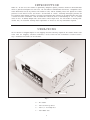
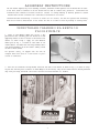
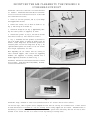
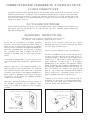
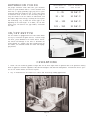
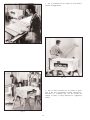
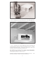
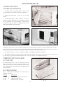
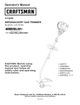
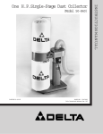
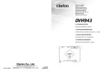
(Model 50-860)
Record this information for future reference.
SERIAL NO. __________________________________
D ATE O F P U R C H A S E __________________________
See Table of Contents for location of Identification Plate.
Dated 5-10-98
PA RT NO. 410-09-651-0001
'Delta International Machinery Corp. 1998
INSTRUCTION M A N U A L
Air Cleaner
TA B L E O F C O N T E N T S
SAFETY RULES ..............................................................................................................................................3
SAFETY RULES F O R AIR CLEANERS .........................................................................................................4
INTRODUCTION..............................................................................................................................................5
U N PACKING....................................................................................................................................................5
A S S E M B LY INSTRUCTIONS..........................................................................................................................6
Using The Air Cleaner On A Bench Or Floor Surface ........................................................................6
Mounting The Air Cleaner To A Ceiling Or Overhead Support..........................................................7
CONNECTING AIR C L E A N E R TO P O W E R S O U R C E...................................................................................8
Power Connections................................................................................................................................8
Motor Specifications ..............................................................................................................................8
Grounding Instructions .........................................................................................................................8
EXTENSION C O R D S ......................................................................................................................................9
ON/OFF SWITCH ............................................................................................................................................9
O P E R ATIONS..................................................................................................................................................9
MAINTENANCE
Changing And Cleaning Filters...........................................................................................................12
IDENTIFICATION PLATE L O C ATION...........................................................................................................12
ACCESSORIES .............................................................................................................................................12
Delta Building Trades and Home Shop Machinery
Two Year Limited Warranty
Delta will repair or replace, at its expense and at its option, any Delta machine, machine part, or machine
accessory which in normal use has proven to be defective in workmanship or material, provided that the
customer returns the product prepaid to a Delta factory service center or authorized service station with
proof of purchase of the product within two years and provides Delta with reasonable opportunity to verify the alleged defect by inspection. Delta may require that electric motors be returned prepaid to a motor
manufacturer s authorized station for inspection and repair or replacement. Delta will not be responsible
for any asserted defect which has resulted from normal wear, misuse, abuse or repair or alteration made
or specifically authorized by anyone other than an authorized Delta Service facility or representative.
Under no circumstances will Delta be liable for incidental or consequential damages resulting from defective products. This warranty is Delta s sole warranty and sets forth the customer s exclusive remedy, with
respect to defective products; all other warranties, express or implied, whether of merchantability, fitness
for purpose, or otherwise, are expressly disclaimed by Delta.
2
Printed in U.S.A.
IMPORTANT SAFETY RULES
As with all machinery there are certain hazards involved with operation and use of the machine. Using the machine with
respect and caution will considerably lessen the possibility of personal injury. However, if normal safety precautions are
overlooked or ignored, personal injury to the operator may result.
This machine was designed for certain applications only. Delta Machinery strongly recommends that this machine
N O T be modified and/or used for any application other than that for which it was designed. If you have any questions relative to its application, DO N O T use the machine until you have first contacted Delta Machinery and we have advised you.
Technical Service Manager
Delta Machinery
4825 Highway 45 North
P.O. Box 2468
Jackson, TN 38302-2468
(IN CANADA: 505 SOUTHGATE DRIVE, GUELPH, ONTARIO
N1H 6M7)
W ARNING: FAILURE TO F O L L O W THESE RULES
M AY RESULT IN SERIOUS P E R S O N A L INJURY
1. F O R Y O U R O W N S A F E T Y, READ INSTRUCTION
M A N U A L B E F O R E O P E R ATING T H E TO O L. Learn the
tool s application and limitations as well as the specific
hazards peculiar to it.
15. DON T O V E R R E A C H. Keep proper footing and balance at all times.
16. MAINTAIN TO O L S IN TO P CONDITION. Keep tools
sharp and clean for best and safest performance. Follow
instructions for lubricating and changing accessories.
2. K E E P G U A R D S IN PLACE and in working order.
3. A LW AY S W E A R E Y E PROTECTION.
17. DISCONNECT TO O L S before servicing and when
changing accessories such as blades, bits, cutters, etc.
4. G R O U N D ALL TO O L S. If tool is equipped with threeprong plug, it should be plugged into a three-hole electrical
receptacle. If an adapter is used to accommodate a twoprong receptacle, the adapter lug must be attached to a
known ground. Never remove the third prong.
18. U S E R E C O M M E N D E D ACCESSORIES. The use of
accessories and attachments not recommended by Delta
may cause hazards or risk of injury to persons.
19. AVOID ACCIDENTA L STARTING. Make sure switch is
in OFF position before plugging in power cord.
5. R E M O V E A D J U S T I N G K E Y S A N D W R E N C H E S.
Form habit of checking to see that keys and adjusting
wrenches are removed from tool before turning it on.
20. N E V E R STA N D O N TOOL. Serious injury could occur
if the tool is tipped or if the cutting tool is accidentally
contacted.
6. K E E P W O R K A R E A C L E A N. Cluttered areas and
benches invite accidents.
21. C H E C K D A M A G E D PA R T S. Before further use of the
tool, a guard or other part that is damaged should be carefully checked to ensure that it will operate properly and
perform its intended function check for alignment of moving parts, binding of moving parts, breakage of parts, mounting, and any other conditions that may affect its
operation. A guard or other part that is damaged should be
properly repaired or replaced.
7. DON T U S E IN D A N G E R O U S ENVIRONMENT. Don t
use power tools in damp or wet locations, or expose them
to rain. Keep work area well-lighted.
8. K E E P CHILDREN A N D VISITO R S AW AY. All children
and visitors should be kept a safe distance from work area.
9. M A K E W O R K S H O P CHILDPROOF
with padlocks,
master switches, or by removing starter keys.
22. DIRECTION O F FEED. Feed work into a blade or
cutter against the direction of rotation of the blade or cutter
only.
10. DON T FORCE TO O L. It will do the job better and be
safer at the rate for which it was designed.
23. NEVER LEAV E TO O L RUNNING UNATTENDED. TURN
P O W E R OFF. Don t leave tool until it comes to a complete
stop.
11. U S E RIGHT TO O L. Don t force tool or attachment to do
a job for which it was not designed.
12. W E A R P R O P E R A P PA R E L. No loose clothing, gloves,
neckties, rings, bracelets, or other jewelry to get caught in
moving parts. Nonslip footwear is recommended. Wear
protective hair covering to contain long hair.
24. DRUGS, ALCOHOL, MEDICATION. Do not operate
tool while under the influence of drugs, alcohol or any
medication.
25. M A K E S U R E TO O L IS D I S C O N N E C T E D F R O M
P O W E R SUPPLY while motor is being mounted, connected
or reconnected.
13. A LW AY S U S E SAFETY GLASSES.W ear safety glasses
(must comply with ANSI Z87.1). Everyday eyeglasses only
have impact resistant lenses; they are not safety glasses.
Also use face or dust mask if cutting operation is dusty.
26. W ARNING: The dust generated by certain woods and
wood products can be injurious to your health. Always
operate machinery in well ventilated areas and provide for
proper dust removal. Use wood dust collection systems
whenever possible.
14. S E C U R E W O R K. Use clamps or a vise to hold work
when practical. It s safer than using your hand and frees
both hands to operate tool.
3
SAFETY RULES F O R
AIR C L E A N E R S
1. F O R Y O U R O W N SAFETY, READ INSTRUCTION
M A N U A L BEFORE OPERATING THE TO OL. Learn the
tool s application and limitations as well as the specific
hazards peculiar to it.
10. M A K E W O R K S H O P CHILDPROOF by unplugging
tools from power source, using padlocks, or by using a
master switch.
11. MAINTAIN TO O L S IN TO P CONDITION. Keep filters
clean for optimum performance. Follow instructions for
changing and cleaning filters.
2. D O N O T AT T E M P T TO R E M O V E O R R E P L A C E
T H E FILTER(S) WHILE T H E MACHINE IS IN O P E R ATION. M A K E C E R TAIN AIR C L E A N E R IS DISCONN E C T E D F R O M THE POWER S O U R C E.
12. DANGER: D O N O T use this machine to filter any
metal dust. Combining wood and metal dust can create
an explosive hazard. This Air Cleaner is intended to be
used to filter non-explosive atmospheres only.
3. D O N O T O P E R ATE THE AIR C L E A N E R WITHOUT
THE FILTER IN PLACE TO AVOID EXPOSURE TO ROTATING PARTS A N D OVERLOADING THE M O TO R.
13. IF Y O U A R E N O T thoroughly familiar with the operation of the Air Cleaner, obtain advice from your supervisor, instructor or other qualified person.
4. THE U S E of filters and attachments not recommended by Delta may result in product damage or the risk of
personal injury.
14. W ARNING: D O N O T operate your Air Cleaner until it
is completely assembled and installed according to the
instruction manual.
5. When suspending the Air Cleaner from the ceiling,
M A K E C E R TAIN the hardware is securely anchored into
a wood structure. Always keep a minimum of 7 feet
between bottom of Air Cleaner and the floor surface to
allow for adequate head clearance. Also, use only properly sized chain to prevent the tool from falling.
15. PLACE P O W E R C O R D IN A SAFE L O C ATION TO
ELIMINATE TRIPPING HAZARDS.
6. TO R E D U C E THE RISK O F ELECTRICAL SHOCK,
do not expose to water or rain, and do not lift the Air
Cleaner by the power cord. D O N O T use the power cord
as a hanging device.
16. USE FA C E O R DUST MASK AND EYE PROTECTION.
W ARNING: The dust generated by certain woods and
wood products can be injurious to your health. Always
operate machinery in well-ventilated areas and provide
for proper dust removal.
7. When used in the portable application, M A K E C E RTAIN the Air Cleaner is adequately supported, or securely
clamped to the work surface to eliminate any potential for
movement or damage from falling.
17. W ARNING: TO AVOID A POTENTIALLY DANGERO U S SITUATION, DO N O T U S E AIR CLEANER TO DISSIPATE F U M E S O R SMOKE. This Air Cleaner is intended
for use in non-explosive, non-metallic atmospheres where
only dry airborne dust is present.
8. A LW AY S W E A R A D E Q U ATE E Y E PROTECTION.
18. GROUND the Air Cleaner per National Electric Code
(N.E.C.) requirements.
9. W H E N N O T IN USE, BE C E R TAIN TO STO R E AIR
C L E A N E R IN A SAFE L O C ATION TO ELIMINATE THE
POTENTIAL O F D A M A G E TO THE P O W E R C O R D O R
TRIPPING H A Z A R D S.
19. S AV E THESE INSTRUCTIONS. Refer to them frequently and use them to instruct other users.
4
INTRODUCTION
Model No. 50-860 Delta Air Cleaner is specifically designed to quietly circulate and filter non-metallic dust
which is generated throughout the work area. The Air Cleaner is furnished with two filters: a disposable outer
filter which filters out 98% of particles five microns in size; and the secondary filter will capture 85% of dust
particles of one micron in size (one micron = one millionth of a meter). Breathing microscopic particles can
be a potential health hazard; therefore, filtering out microscopic dust particles of the mentioned sizes will offer
a cleaner and safer environment. This Air Cleaner will filter the air in a room measuring 20 x 20 x 8 sixteen
times an hour. If desired, multiple units can be used to filter larger areas. The Air Cleaner is virtually maintenance free; an occasional cleaning and/or replacement of filters is the only maintenance required.
U N PACKING
The Air Cleaner is shipped complete in one shipping container.Carefully unpack the Air Cleaner and all loose
items from the shipping container.W ARNING: D O N O T LIFT T H E AIR C L E A N E R B Y P O W E R C O R D.
Fig. 2 illustrates the contents of the container.
A
B
C
D
Fig. 2
A - Air cleaner
B - Four one-inch eye-bolts
C - Four 1/4 -20 flange nuts
D - Four rubber feet
5
A S S E M B LY INSTRUCTIONS
The Air Cleaner requires very little assembly; therefore, determine in which position the Air Cleaner will be used on the floor, bench or overhead. If the Air Cleaner will be used as a mobile unit, proceed to USING THE AIR
C L E A N E R O N A B E N C H O R F L O O R S U R FA C E section. If ceiling mounting is desired, proceed to section
MOUNTING THE AIR C L E A N E R TO A CEILING O R O V E R H E A D S U P P O R T.
IMPORTA N T:When determining a location to mount the air cleaner, the unit will operate more efficiently
when the air flow is unrestricted. Do not locate the unit in a corner or near any heating or cooling vents.
USING THE AIR C L E A N E R O N A B E N C H O R
F L O O R S U R FA C E
1. Locate (4) self-adhesive rubber feet (A) Fig. 3, supplied with the unit. Carefully place Air Cleaner on a firm
supporting surface so there is access to the bottom of the
cabinet as shown in Fig. 3. Apply one self-adhesive
rubber pad (A) Fig. 3, to bottom at each corner of air
cleaner cabinet. The rubber feet will help eliminate vibration and the possibility of the air cleaner walking across
the work or floor surface.
For operator safety, we suggest that the unit be
clamped down when used on a work bench or positioned on sawhorses.
A
Fig. 3
2. There are two convenient lifting handles located on each side of the cabinet as shown in Fig. 4, to assist in carrying the unit from one place to another.To avoid damage to the air filters, carry the air cleaner with the filters positioned
away from your body.CAUTION: THIS TO O L WEIGHS APPROXIMATELY 50 POUNDS.
Fig. 4
6
MOUNTING THE AIR C L E A N E R TO T H E CEILING O R
OVERHEAD SUPPORT
W ARNING: THIS TO O L W E I G H S A P P R O X I M ATELY
50 POUNDS. MAKE C E R TAIN THE UNIT IS S E C U R ELY S U P P O R T E D W H E N M O U N T I N G TO A CEILING
O R O V E R H E A D S U P P O R T.
E
F
C
1. Locate (4) one inch eye-bolts, and (4) 1/4-20 flange
nuts supplied with the unit.
2. Remove four screws, one of which is shown at (C)
Fig. 5, from the top of air cleaner (D).
3. Thread one flange nut (E) Fig. 5, approximately halfway onto each eye-bolt (F) supplied, as shown.
D
4. Thread each eye-bolt (F) Fig. 5, into each of the four
holes where screws (C) were removed in STEP 2.
Fig. 5
5. Fig. 6, illustrates the four eye-bolts (F) attached to
top of air cleaner.NOTE: To adjust the height of the air
cleaner, loosen flange nuts (E) and rotate eye-bolts as
necessary.Make certain the flange nuts (E) Fig. 6, are
tightened down against the surface of the air cleaner
after height adjustments are made.
F
E
When suspending the air cleaner from the ceiling or
other overhead support, make certain the supporting
hardware (not supplied) is securely anchored into a
wooden supporting structure as shown in Fig. 7.
W ARNING: N E V E R S E C U R E MOUNTING H A R D WA R E
TO D RY WALL, DROP CEILING TILE/FRAME, OR NONSTRUCTURAL M E M B E R S.
Fig. 6
Fig. 7
W ARNING: Keep a minimum of seven feet between bottom of air cleaner and the floor surface.
DO NOT use rope, cable or power cord to suspend the unit from the ceiling. We recommend that a chain should
be used and rated for a minimum of a 100 lb. working load to firmly support the air cleaner. IMPORTA N T:W h e n
determining a location to mount the unit, the air cleaner will operate more efficiently when the air flow is unrestricted. Do not locate the unit in a corner or near any heating or cooling vents.
7
CONNECTING AIR C L E A N E R TO P O W E R S O U R C E
P O W E R CONNECTIONS
A separate electrical circuit should be used for your tools.This circuit should not be less than #12 wire and
should be protected with a 20 Amp fuse. Have a certified electrician replace or repair a worn cord immediately.Before connecting the motor to a power line, make sure the switch is in the OFF position and be sure
that the electric current is of the same characteristics as stamped on the motor nameplate. Running on low
voltage will damage the motor.
M O TO R SPECIFICATIONS
Your Air Cleaner is wired for 110-120 volt, 60 Hz alternating current. Before connecting the Air Cleaner to the
power source, make sure the switch is in the OFF position. The 1050 RPM motor quietly circulates 850
cubic feet of air per mnute.
GROUNDING INSTRUCTIONS
CAUTION: THIS TO O L MUST BE GROUNDED WHILE IN USE
TO PROTECT THE OPERATOR FROM ELECTRIC SHOCK.
In the event of a malfunction or breakdown, grounding
provides a path of least resistance for electric current to
reduce the risk of electric shock. This tool is equipped
with an electric cord having an equipment-grounding conductor and a grounding plug. The plug must be plugged
into a matching outlet that is properly installed and
grounded in accordance with all local codes and ordinances.
Use only 3-wire extension cords that have 3-prong
grounding type plugs and 3-hole receptacles that accept
the tool’s plug, as shown in Fig. 8.
Repair or replace damaged or worn cord immediately.
This tool is intended for use on a circuit that has an outlet and a plug that looks like the one shown in Fig. 8.
A temporary adapter, which looks like the adapter illustrated in Fig. 9, may be used to connect this plug to a
2-pole receptacle, as shown in Fig. 9, if a properly
grounded outlet is not available. The temporary adapter
should be used only until a properly grounded outlet can
be installed by a qualified electrician. THIS ADAPTER IS
NOT APPLICABLE IN CANADA. The green-colored
rigid ear, lug, and the like, extending from the adapter
must be connected to a permanent ground, such as a
properly grounded outlet box, as shown in Fig. 9.
Do not modify the plug provided - if it will not fit the outlet, have the proper outlet installed by a qualified electrician.
Improper connection of the equipment-grounding conductor can result in risk of electric shock. The conductor
with insulation having an outer surface that is green with
or without yellow stripes is the equipment-grounding conductor.Ifrepair or replacement of the electric cord or plug
is necessary, do not connect the equipment grounding
conductor to a live terminal.
CAUTION: IN ALL CASES, MAKE CERTAIN THE RECEPTACLE IN QUESTION IS PROPERLY GROUNDED.
IF YOU ARE NOT SURE HAVE A CERTIFIED ELECTRICIAN CHECK THE RECEPTACLE.
Check with a qualified electrician or service personnel if
the grounding instructions are not completely understood, or if in doubt as to whether the tool is properly
grounded.
GROUNDED OUTLET B O X
GROUNDED OUTLET B O X
CURRENT
C A R RYING
PRONGS
GROUNDING MEANS
ADAPTER
GROUNDING BLADE IS
LONGEST OF THE 3 BLADES
Fig. 8
Fig. 9
8
EXTENSION C O R D S
TO TA L LENGTH OF
CORD IN FEET
Use proper extension cords. Make sure your extension
cord is in good condition and is a 3-wire extension cord
which has a 3-prong grounding type plug and a 3-pole
receptacle which will accept the tool s plug. When using
an extension cord, be sure to use one heavy enough to
carry the current of the air cleaner.An undersized cord
will cause a drop in line voltage, resulting in loss of power
and overheating. Fig. 10 shows the correct gage to use
depending on the cord length. If in doubt, use the next
heavier gage. The smaller the gage number, the heavier
the cord.
GAGE OF EXTENSION
CORD TO USE
0 - 25
18 AW G
26 - 50
16 AW G
51 - 100
14 AW G
101 - 150
12 AW G
Fig. 10
ON/OFF SWITCH
N
The Air Cleaner is equipped with an in-line rocker switch
(M) Fig.11, located on the power cord (N). To start or stop
the motor, press downward on the rocker switch. NOTE:
The switch has markings on the side to determine the
on/off position. W e suggest that when finished with the
air cleaner, the switch be turned off rather than unplugging the unit.
M
Fig. 11
O P E R ATIONS
1. NOTE: The air cleaner may produce a slight odor for the first couple hours of operation due to the protective coating
which is applied to internal components. This odor will dissipate and should be disregarded. IMPORTA N T:Never operate the air cleaner without air filters in place.
2. Fig. 12 illustrates the air cleaner as it can be used in bench-top sanding applications.
Fig. 12
9
3. Fig. 13 illustrates the air cleaner as can be used in
circular saw applications.
Fig. 13
Fig. 14
4. Figs. 14 and 15 illustrate the air cleaner as can be
used in dry wall and basement cleaning applications.
CAUTION: W e recommend that the air cleaner be
clamped, as shown, if using sawhorses as a supporting
surface.
Fig. 15
10
Fig. 16
5. Fig. 16, illustrates the air cleaner being used in a floor sanding application.
Fig. 17
6. Fig. 17, illustrates the air cleaner suspended from wooden ceiling supports for
overhead operation. CAUTION: A LW AY S MAINTAIN AT LEAST A 7 C L E A RA N C E B E T W E E N THE B O T TOM OF T H E AIR C L E A N E R A N D T H E F L O O R
S U R FACE FOR H E A D CLEARANCE/PROTECTION.
When suspending the air cleaner from the ceiling or other overhead support,
make certain the supporting hardware (not supplied) is securely anchored into a
wooden supporting structure as shown in Fig. 17.
W ARNING: N E V E R S E C U R E MOUNTING H A R D WA R E TO D RY WALL, DROP
CEILING TILE/FRAME, OR NON-STRUCTURAL M E M B E R S.
11
MAINTENANCE
CHANGING A N D
CLEANING FILTERS
1. To remove the outer first stage filter (H) Figs. 18 and
19,lift and pull out the bottom of the filter as shown.
2. Remove inner bag filter (J) Fig. 19, in the same
manner.
3. The first stage filter (H) Figs. 18 and 19, can be replaced or cleaned depending on its condition. This filter
can be cleaned in one of two methods: a shop-vac can
be used to remove the dust, or compressed air can be
used to blow the dust out of the filter.
H
Fig. 18
low
Air F
K
H
J
Fig. 19
Fig. 20
W ARNING: C O M P R E S S E D AIR C A N B E DANGEROUS. F O R O P E R ATO R SAFETY,D O N O T EXCEED A N AIR PRESS U R E O F 30 PSI O R POINT AIR NOZZLE TO WA R D A N Y O N E O R AIM AIR NOZZLE AT Y O U R O W N B O D Y.A LW AY S
W E A R SAFETY GLASSES A N D D U S T M A S K W H E N PERFORMING THIS PROCEDURE.
4. The inner bag filter (J) Fig. 19, cannot be cleaned; it is disposable and must be replaced.
5. Install both filters in the reverse order in which they were removed. NOTE: Make certain the AIR F L O W A R R O W
on each filter is pointing inward toward the rear of the air cleaner, as illustrated in Fig. 19.
IDENTIFICATION PLATE
L O C ATION
J
The identification plate (K) Fig. 20, showing the serial
number and model of the air cleaner, is located at the
rear of the air cleaner, directly below power cord. Please
write these numbers on the front cover of this manual for
future reference.
H
ACCESSORIES
Fig. 21, illustrates the replacement air filters that are
available from Delta.
PA R T NO.
50-858
50-859
50-857
DESCRIPTION
(H)
(J)
Disposable Pleated Filter (pre-filter)
3-pocket Internal Filter
Charcoal Filter (not shown)
Fig. 21
12