1
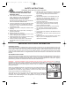
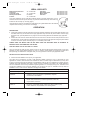
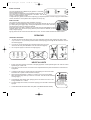
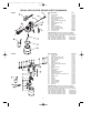
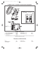
N0150 05/05.qxd
27/5/05
10:28 am
Page 1
HV7000A / HV7000P
OPERATING INSTRUCTIONS
Thank you for purchasing the Earlex Spray Port.
This is a highly versatile spray kit and can be used on a variety of applications.
BEFORE USE - PLEASE READ THE SAFETY & OPERATING INSTRUCTIONS.
Please retain for future reference
N0150 05/05.qxd
27/5/05
10:28 am
Page 2
SAFETY INSTRUCTIONS
WARNING! FIRE AND EXPLOSION HAZARD.
NEVER, under any circumstances, point the spray
CAUTION: TO REDUCE THE RISK OF
gun at another person or animal. In the event of
ELECTRIC SHOCK OR INJURY, USE
injury occurring, seek expert medical advice
INDOORS ONLY.
The substances used with this spray applicator
(paint, thinners etc) may contain hazardous,
harmful, explosive or corrosive materials.
ALWAYS COMPLY WITH THE SAFETY
INSTRUCTIONS ISSUED WITH THIS PRODUCT
AND THE MATERIAL BEING USED.
The spray applicator must only be used with paints
and solvents that have a suitable flash point for
spraying. If in doubt, consult the paint or solvent
manufacturer's data
Always ensure there is adequate ventilation when
spraying.
NEVER spray near an open flame, including an
appliance pilot flame.
NEVER smoke when spraying.
Always disconnect the unit from the mains supply
when re-filling the paint container.
Always disconnect the unit from the mains supply
when cleaning the spray applicator.
Always ensure the spray area is safe and free
from all debris that may present a fire or trip
hazard.
immediately.
NEVER allow children or unauthorised users to
operate or play with the spray equipment. This
equipment is for professional use only.
Always read the paint manufacturer's thinning
instructions before use.
Always wear the correct protective face mask
when spraying. We also recommend wearing
gloves, goggles and overalls.
After every use ensure that you clean the spray
gun thoroughly & grease the gland washer.
Use only genuine manufacturer replacement
parts.
Only use the spray equipment as detailed in these
instructions.
Do not use the air hose or mains cable to pull the
turbine unit.
Check the hoses, hose connectors & mains cable
daily. Any worn or damaged parts should be
replaced immediately.
IMPORTANT ELECTRICAL INFORMATION
EXTENSION CORDS
Your Earlex Spray Port is supplied with a power cord that is 6 feet long. If you need an extension cord, use
only a 3 wire extension cord that has a 3 blade grounding plug, and a 3 slot receptacle that will accept the plug
on the product. Make sure your extension cord is in good condition. When using an extension cord, be sure
to use one heavy enough to carry the current your product will draw. For lengths less than 25 feet, No 16AWG
extension cords should be used. For lengths between 25 feet and 50 feet, No 12 AWG extension cords should
be used.
GROUNDING INSTRUCTIONS
This product must be grounded. In the event of an electrical short circuit, grounding reduces the risk of electric
shock by providing an escape wire for the electric current. This product is equipped with a cord having a
grounding wire with an appropriate grounding plug. The plug must be plugged into an outlet that is properly
installed and grounded in accordance with all local codes and ordinances.
DANGER :- Improper installation of the grounding plug can result in a risk of electric shock. If repair or
replacement of the cord or plug is necessary, do not connect the grounding wire to either of the flat blade
terminals. The wire with insulation having an outer surface that is green with, or
without, yellow stripes is the grounding wire and this must be connected to the
plug's grounding pin.
Check with a qualified electrician or serviceman if the grounding instructions are
not completely understood, or if in doubt as to whether the product is properly
grounded. Do not modify the plug provided if it will not fit the outlet, have the
proper outlet installed by a qualified electrician.
This product is for use on a nominal 120 volt circuit and has a grounding plug
that looks like the plug illustrated in Fig.1. Make sure that the product is
connected to an outlet having the same configuration as the plug. No adapter
should be used with this product.
2
Fig.1
MAINS
SWITCH
SHOWN IN
OFF
POSITION
Fig.2
N0150 05/05.qxd
27/5/05
10:28 am
Page 3
INTRODUCTION
The Earlex HV7000 “Spray Port” is an industrially rated, portable, paint spraying system and is intended for
use by professionals. HVLP stands for High Volume, Low Pressure. This is a type of spraying that allows you
to spray extremely accurately but without all the overspray that occurs with high pressure tank equipment. In
some parts of the world the high pressure systems are banned by law on environmental grounds and HVLP
type systems are the only alternative for professional type spraying. This system is extremely easy to use, very
safe and reduces the amount of paint used.
The Earlex Spray Port (model no. HV7000US) is a portable system that is made up as a trolley unit that can
be broken down into two separate parts, the main Turbine Unit and the Carrier Stand. These two parts connect
together via two quick release clips allowing the complete system to be wheeled from a vehicle to the
workplace or around the workshop. They are easily separated so they can be stored in the back of a van or
truck. The Carrier Stand holds the Air Hose and spray applicator and also has space for a cleaning kit. The
Earlex Spray Port (model no.HV7000 USNF) is supplied with the main turbine unit, hose and gun. Your Spray
Port can be supplied with a plastic spray applicator Type P or, an aluminium spray applicator Type A. Both
types will give identical excellent results.
PLEASE NOTE: We have done all we can to ensure that used correctly and according to these instructions,
this spray applicator will give long and trouble free life. We accept no responsibility for damage caused by the
use of incorrect or unsuitable substances, paints or fluids which have not been thinned correctly or are
unsuitable for the surfaces to which they are applied, health hazards arising from lack of ventilation when
working in confined spaces or failure of the equipment due to inadequate cleaning of the components after use.
If in doubt, always test a small inconspicuous area first. Always read the paint manufacturer’s instructions first.
Neither our guarantee nor the above statement affects your statutory rights.
IMPORTANT BASIC INFORMATION
SELECTING PAINT
This is a highly versatile spray kit that can be used with several different spray mediums including varnishes,
wood preservatives, enamels, oil and water based paints and cellulose. However some materials cannot be
sprayed so please check the recommendation of the manufacturer before buying the paint. If a material refers
to brush application only then it usually cannot be sprayed.
THIS UNIT SHOULD NOT BE USED FOR TEXTURED PAINTS. THESE MATERIALS CONTAIN PARTICLES
OF GRIT THAT WILL CAUSE PREMATURE AND EXCESSIVE WEAR. USE OF SUCH MATERIALS WILL
INVALIDATE THE WARRANTY. TO OBTAIN THE BEST RESULTS FROM YOUR SPRAY KIT PLEASE
READ THE INSTRUCTIONS CAREFULLY BEFORE USE.
SURFACE PREPARATION
Preparation of the surface and thinning of the paint are the two most important areas to be concerned with to
obtain the best results from your spray kit. Ensure all surfaces are free from dust, dirt, rust and grease. If
necessary smooth with sandpaper, or similar. Taping of areas is important to ensure you do not spray those
areas you wish to remain untouched.
THINNING
Your spray kit is supplied with a viscosity cup. Viscosity is a technical term used to indicate if a product is very
thin or very thick. If thin, the viscosity is said to be low, while if very thick the viscosity is said to be high.
Viscosity is measured in seconds. In order to spray some materials they need to be “thinned” (diluted).
Thinning is very important when spraying. Most paints are supplied ready for brush application and may need
to be thinned (diluted) for spraying purposes.
Follow the manufacturers guide for thinning in conjunction with a spray applicator. If in doubt please contact
the manufacturers of the paint. The viscosity cup supplied will help you determine the correct thickness of the
paint. Paint is “thinned” by adding the substance which the paint is based upon. If a water based paint then
water is added, if oil based then white spirit, if cellulose then a cellulose thinner is added.
As some paints, wood preservatives and other sprayable materials contain particles that have differing
qualities, please ensure that when filling the paint container of the spray applicator, that the paint is filtered
through either a funnel with a filter on it or through nylon tights or stockings. This will ensure that no large
particles enter the paint container, so preventing blockages and providing you with trouble free spraying.
Ensure that a face mask, gloves and goggles are worn at all times when spraying.
3
N0150 05/05.qxd
27/5/05
10:28 am
Page 4
IDEAL VISCOSITY
Water based paints and
emulsions
Oil based paints
Wood preservatives
Primers
45 - 60 seconds
Varnishes
Aluminium paints
Wood stains
Cellulose
45 - 50 seconds
No dilution
45 - 50 seconds
Manufacturers
Manufacturers
Manufacturers
Manufacturers
ratio
ratio
ratio
ratio
This spray applicator can be used with products having a viscosity ranging from 10 to a
maximum of 60 seconds. Dip the viscosity cup into the material and fill up. Time how long
it takes for the viscosity cup to empty (Fig.3).
Using the above chart (or manufacturer’s instructions) as a guide determine if the material
requires further thinning, if so then thin accordingly.
Fig.3
OPERATION
PREPARATION
Fill the paint container with the material to be sprayed. DO NOT OVERFILL above MAX level indicator. Push
the Feed Tube firmly into the base of the spray applicator body and re-fit the paint container into the spray
applicator body. (See exploded view on page 8 to show the fitting detail for the different spray applicator
types.)
Unwind the hose from the Carrier Stand & screw the motor end of the hose to the outlet port at the front of
the turbine unit. Connect the spray applicator end of the hose to the spray applicator using the quick release
connector. Uncoil the power cord and plug it in to a suitable power outlet.
ALWAYS KEEP THE MOTOR UNIT AS FAR AWAY FROM THE SPRAYING AREA AS POSSIBLE TO
PREVENT PAINT CONTAMINATING THE MOTOR.
TAPE ANY AREA YOU DO NOT WISH TO SPRAY.
Once you have set up ready to spray, switch on the unit. No paint will be sprayed until the trigger on the spray
applicator is gently pulled. Before starting any work on spraying actual objects we suggest you spend some
time practicing on cardboard or newspaper until you have got used to how the spray applicator works.
SETTING UP YOUR SPRAY APPLICATOR
Choose the best Needle & Fluid Tip for your application.
Your Spray Port is supplied to you with a 0.08” diameter Needle & Fluid Tip. This is a good size for most
applications. However, there are other sets available to cater for a wider range of materials that you may want
to spray. In general, the larger the diameter of the Needle & Fluid Tip, the more suitable it is for higher viscosity
materials. The larger diameters also allow a greater volume of material to be applied. The smaller diameters
are more suitable for low viscosity materials & lighter application. For the Spray Port type “P”, Needle & Fluid
Tip sets are available at 0.04” and 0.06” diameter. For the Spray Port type “A”, Needle & Fluid Tip sets are
available at 0.04”, 0.06” and 0.10” diameter. See page 8 for details.
NEEDLE SELECTION GUIDELINES
Needle/Fluid Tip Size
Material
0.04/0.06”
Cellulose, Acrylics, Synthetics, Polyurethane, Lacquers,
Fluorescents, Wood Stains
0.06/0.08”
Oil base, Hammers, Oxides, Primers, Air Drying, Enamels, Varnish,
Marine Paint, Multi-Colour, Industrial Synthetics, Latex Oils,
Polyurethane, Aluminium
0.08/0.10”
Emulsions, Chlorinated rubber, Oxides, Zinc Rich Primers, Epoxy
Plastic Adhesives, Polyurethane, Floor Paving Paints
4
N0150 05/05.qxd
27/5/05
10:28 am
Page 5
SPRAY PATTERNS
Fig.4
The spray applicator has 3 different spray patterns – Horizontal,
Vertical and Round (Fig.4)
The horizontal and vertical are recommended for large surfaces.
Vertical Jet
Horizontal Jet
Round Jet
The round spray is used for small objects or for areas - such as
corners – that are difficult to reach.
To adjust the spray pattern, loosen the Air Cap Ring (1), adjust the position of the Air Cap (2) to obtain either a
vertical, horizontal or round pattern then re-tighten the aircap ring.
PAINT VOLUME
The volume of paint sprayed is easily adjustable. (Fig.5(a))
Completely close Fluid Adjusting Screw (8) by turning this clockwise as far as it will
go. Whilst pulling the trigger, begin turning the adjustment screw counter-clockwise
until the volume of paint you require is obtained.
If the paint spray is too wide or contains too much paint turn the Fluid Adjusting Screw
clockwise again. Once the correct spray pattern & paint volume is obtained, you are
ready to begin spraying.
Fig.5
Fig.5(b) shows the Air Volume Control Valve set for ‘FULL’ air flow. Rotate clockwise to reduce air flow.
SPRAYING
SPRAYING TECHNIQUE
1. To obtain the best results always keep your spray applicator level and spray equally from side to side
or up or down 10”-12” (25-30cm) from the surface. Avoid spraying at an angle as this will lead to runs on
the surface (Fig.6a).
2. Let your arm control the left to right movement rather than your wrist
as this will aid even paint distribution over the whole area (Fig.6b).
3. Do not tip the sprayer to more than 45˚angle (Fig.6c).
Fig.6a
Fig.6b
Fig.6c
HELPFUL HINTS
1. Evenly control the speed of movement of the spray applicator. A fast speed will give a thin coat and a slow
speed will give a thick coat.
2. Only apply one coat at a time. If a further coat is required follow the paint manufacturer’s instructions for
drying times.
3. If spraying small areas or objects keep the output setting low as this will avoid
excessive use of paints and will minimise overspray.
4. When spraying large areas or objects, it is best to use a criss-cross pattern,
either from left to right then up or down or vice-versa. This will ensure maximum
coverage (Fig.7).
5. Avoid stopping and starting when spraying as this can lead to too much or not
enough material on a surface.
6. To ensure edges are covered, commence spraying just to the side of area being
sprayed.
7. CLEAN SPRAYER AFTER EVERY USE (SEE CLEANING INSTRUCTIONS)
5
Let go of the trigger at the
end of each spray
movement to avoid
excessive paint and drips
Fig.7
N0150 05/05.qxd
27/5/05
10:28 am
Page 6
CLEANING INSTRUCTIONS
Remember to disconnect the unit from the mains power when undertaking any cleaning of the Spray Port.
THE SPRAY APPLICATOR MUST BE THOROUGHLY CLEANED IMMEDIATELY AFTER USE. IF THE
PAINT DRIES INSIDE THE GUN, CLEANING WILL BECOME MUCH MORE DIFFICULT AND MAY RENDER
THE GUN INOPERABLE. THIS IS NOT COVERED BY WARRANTY.
The spray applicator is the same as a paintbrush, if it is not cleaned it will go hard and can become useless.
You must therefore clean this out after use.
SPRAY APPLICATOR
1. Remove the gun container.
4. Clean any traces of paint off the outside of the
spray applicator.
2. Pour any leftover paint into its container so that it
can be used for the future.
5. Clean the container Seal inside the spray
applicator body for Type P or inside the spray
applicator body for Type A.
3. Pour a quantity of the respective thinner into
container, shake the spray applicator lightly,
reassemble the gun, then spray this liquid
through the gun. Repeat this until the thinner
being sprayed is coming through with
no traces of paint.
FLUID TIP & NEEDLE (Type P)
8. Remove Fluid Tip Seal (5)
9. Remove Paint Container Seal (12)
10. Place all of these items into a container and clean
them using a brush and clean thinners
11. Clean the inside of the body of the gun
12. Thoroughly dry these parts before reassembling
13. Grease the Gland (10)
14. Reassemble parts in reverse order
1.
2.
3.
4.
5.
Unscrew Air Cap Ring (1)
Remove the Air Cap (2)
Completely remove Fluid Adjusting Screw (8)
Remove the Spring (7)
Remove the Fluid Tip Needle (6) by gently pulling
the trigger
6. Remove Direction Plate noting the position of
notches (3)
7. Remove the Fluid Tip (4)
It is recommended fitting the Fluid Tip (4) prior to the needle
FLUID TIP & NEEDLE (Type A)
1.
2.
3.
4.
Remove the Air Cap Ring (1)
Remove the Air Cap (2)
Remove Direction Plate & Spring Assembly (3)
Unscrew Adjusting Screw (12) & pull out the
Needle (9) & Needle Spring (11).
5. Use the spanner supplied to remove the Fluid Tip
(4) & Fluid Tip Seal (5)
6. Immerse all of the parts above in thinners & clean
them thoroughly using the cleaning kit supplied
with the gun.
7. Before refitting the Needle, dip its end into some
vasaline. This will automatically lubricate the
gland washer as it is inserted.
8. The external surfaces of the spray applicator can
be wiped clean with a cloth soaked in thinners.
NEVER DISPOSE OF PAINTS OR SOLVENTS INTO DRAINS. CONTACT YOUR LOCAL COUNCIL TO
ARRANGE COLLECTION OR FOR DETAILS OF NEAREST REGISTERED DISPOSAL SITE.
TURBINE UNIT AND CARRIER STAND
The Turbine unit and the Carrier and Stand can be cleaned using a damp cloth and a little thinners to
remove paint stains.
6
N0150 05/05.qxd
27/5/05
10:28 am
Page 7
MAINTENANCE
SPRAY APPLICATOR
Keep the internal workings of the spray applicator clean. The spray applicator should be thoroughly cleaned
after each use. Follow the cleaning instructions on page 6 with reference to the drawings on page 8
Check the needle and fluid tip on a regular basis for excessive wear, and replace as necessary. See the
cleaning instructions for the correct procedure for removing these parts. Replacement needle sets are
available from Earlex Inc.
Keep all moving parts lubricated with a light smear of ‘silicone free’ grease.
Lubricate the gland washer, after each time you clean it, with a light smear of ‘silicone free’ grease.
Check there is no leakage from the gland washer. If there is, tighten the gland nut a little to ensure a seal
with the needle. Do not over-tighten this nut, also ensure the gland washer has not dried out. If it has,
lubricate it as above.
TURBINE UNIT
Check the condition of the cartridge filter that is housed in the front cover. This is easily removed by sliding
it upwards. If it is clogged, remove it and blow out using an airline or washed out using a mild detergent if
necessary.
Keep the outer surface of the air hose free from harmful substances such as petrol, cellulose thinners, paint
strippers & oil. Prolonged exposure to such substances may cause irreparable damage. Always check and
clean off any excess immediately.
Check the condition of the power cord regularly. If there are any cuts or serious abrasions to the outer
sheath, replace it immediately. When the unit is not in use, keep the power cord coiled around the brackets
at the back of the turbine case. When the unit is being used, protect the power cord and any extension cord
from damage that could be caused, for example, by traffic or hazardous substances.
The turbine unit can only be fully serviced by authorised service agents.
7
N0150 05/05.qxd
27/5/05
10:28 am
Page 8
SPRAY APPLICATOR SPARE PARTS DRAWINGS
8
TYPE P
Key Description
No.
01. Air Cap Ring
02. Air Cap
03. Spray Direction Plate
04. 0.08” (2.0mm) Fluid Tip
05. Fluid Tip Seal
06. 0.08” (2.0mm) Fluid Needle
07. Spring
08. Fluid Adjusting Screw
09. Gland Nut
10. Gland
11.
Paint Feed Tube
12. Paint Container Seal
13. Paint Container (Clear)
14. Hose Assembly
15. Viscosity Cup
14
7
6
9
5
10
4
3
2
1
L0215
L0238
L0206
L0237
L0211
L0236
L0216
L0210
L0208
L0272
L0214
L0212
L0201
N0099
SG243
Optional Extras: Nozzles & Fluid Tips of different
sizes can be obtained as sets under the following
accessory numbers. Please call our Toll Free helpline
to order these on 800 252 1288.
0.04” dia Fluid Tip, Needle & seal
HVACC10R
0.06” dia Fluid Tip, Needle & seal
HVACC15R
0.08” dia Fluid Tip, Needle & seal
HVACC20R
11
15
Part
12
13
TYPE A
10 11
9
1
3
2
4
5
6
7
8
7
13
17
14
18
15
16
26
19
20
21
22
27
12
Key Description
1.
Air Cap Ring
2.
Air Cap
3.
Air Direction Plate Assy
4.
0.08” (2.0mm) Fluid Tip
5.
Fluid Tip Seal
6.
Pivot Screw
7.
Washer
8.
Main Body Assy
9.
0.08” (2.0mm) Fluid Needle
10. Adaptor
11.
Spring
12. Adjusting Screw
13. Pivot
14. Air Feed Tube
15. Gland Nut
16. Gland Washer (2 pcs)
17. Operating Lever
18. Centre Bolt & Pick Up Tube Assy
19. Yoke
20. Clamp Lever
21. Shim
22. Lid Assy
23. Gasket
24. Centre Bolt Nut
25. Paint Container
26. Viscosity Cup
27. Spanner
Part No.
L0151
L0517
L0162
L0157
L0159
L0179
L0195
L0180
L0166
L0174
L0175
L0176
L0178
L0182
L0173
L0168
L0177
L0183
L0184
L0185
L0186
L0187
L0188
L0189
L0190
SG243
L0191
23
Optional Extras: Nozzles & Fluid Tips of different
sizes can be obtained as sets under the following
accessory numbers. Please call our Toll Free helpline
to order these on 800 252 1288.
0.04” dia Fluid Tip, Needle & seal
HV5ACC10R
0.06” dia Fluid Tip, Needle & seal
HV5ACC15R
0.08” dia Fluid Tip, Needle & seal
HV5ACC20R
0.10” dia Fluid Tip, Needle & seal
HV5ACC25R
24
25
8
N0150 05/05.qxd
27/5/05
10:28 am
Page 9
TURBINE UNIT & CARRIER STAND PARTS DRAWINGS
1
2
Power IN
(IEC Connector)
Circuit Breaker
3
4
5
6
Mains Switch
(120V)
7
SPARE PARTS LIST
1.
2.
3.
4.
Hose Connector Assembly (29ft 10”) N0099
Semi Hose Reel Moulding
N0116
Carrier Frame Assembly
N0162
Filter Media x 2
N0087
5. Main Frame Assembly
6. Power Cord
7. Motor Unit Assembly
N0161
D42
N0158
FOR INFORMATION ON ALL SPARE PARTS FOR THIS UNIT PLEASE CONTACT PMC ON OUR TOLL
FREE HELPLINE: 800 252 1288
TECHNICAL SPECIFICATION
Volts
Amps
Unrestricted Airflow
Turbine Stages
120V
10A
90cfm
3
Length of mains cable16AWG, 3 wire
Length of hose
Container capacity
9
6ft 10”
29ft 6”
1 Quart
N0150 05/05.qxd
27/5/05
10:28 am
Page 10
TROUBLE SHOOTING
PROBLEM
CAUSE
ACTION REQUIRED
The paint drips
on item
being painted
Paint too diluted
Paint volume
too high
Moving too slowly
Spray gun trigger being
held for too long
Spray gun too close
Add undiluted material
Reduce the paint flow
by turning Fluid Adjusting Screw
Increase speed of application
Release trigger earlier
Paint is thin or
irregular
Increase the distance between
gun and workpiece
Add undiluted material
Increase the paint flow by turning
Fluid Adjusting Screw
Reduce speed of application
Clean the gun
Reduce the distance between
gun and work piece
Add thinner
Clean the spray gun
Clean Paint Feed Tube
Replace air hose
Filter the paint
Refill container
Paint too diluted
Paint volume
too low
Moving too fast
Spray gun clogged
Spray gun too far away
No spray pattern Paint too thick
being produced Gun clogged
Pick up pipe clogged
Air hose split
Gritty paint
Container almost
empty
Spray gun at an angle
Unit will not
start
Ensure Paint Feed Tube
is angled towards paint
Check the condition of
the Filter and clean as neccessary
Check the back of the unit. If the circuit
breaker has tripped, a white push button
indicator will appear. Push in to reset.
If this does not cure the problem, please
refer to your nearest service agent.
Check and reset if required.
Air intake
blocked
Circuit breaker tripped
(HV7000 unit)
House circuit breaker
10
N0150 05/05.qxd
27/5/05
10:28 am
Page 11
NOTES
11
N0150 05/05.qxd
27/5/05
10:28 am
Page 12
Copyright & Design Right Reserved © 2005
Design Registration UK 3015591
WARRANTY
This product is guaranteed for a period of 12 months for ordinary use and 6 months for hire purposes or
where the unit is lent to other users.The guarantee is against faulty manufacture and materials. Whilst
every possible care is taken by Earlex to ensure that our products leave the factory in good working
order, Earlex cannot under any circumstances accept liability for problems or damage caused by their
subsequent use. It is the responsibility of the user to ensure that surfaces to be treated or cleaned are
suitable for spraying. The guarantee does not affect your statutory rights.
Distributed by:
PMC Marketing & Sales Inc, 8261 Hyw 73, Suite F, Stanley, N.C. 28164, USA
Customer Service: Toll Free 800 252 1288
E.mail: [email protected] Website: www.wallpaperstripper.com
© 2005 Earlex Products.
N0150 05/05
12