1
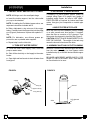
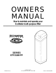
OWNERS MANUAL How to maintain and operate your EcoWater multi-- purpose filter SERIES ETF2100 PF PRINTED IN U.S.A. EcoWater Systems P.O. Box 64420 St.Paul MN 55164 - 9888 Part No. 7283536 (Rev. A 5/10/06) ECOWATER S Y S T E M S Unpacking, Table of Contents UNPACKING EcoWater Multi--Purpose Filters are shipped from the factory in one master carton consisting of ... ...Mineral tank and valve assembly ...Controller cover and timer assembly ...Small parts bags ...Literature kit (includes this manual) NOTE: Filtering mineral is not included. See page 21 for ordering information. Thoroughly check the filter for possible shipping damage and parts loss. Also inspect and note any damage to the shipping carton. Notify the transportation company if damage is present. EcoWater is not responsible for in--transit damages. Remove and discard (RECYCLE) all packing materials. We suggest that you do not open the small parts bags until you are ready to use them. Filter assembly instructions are on page 5. TABLE OF CONTENTS Page Warranty / Safety Guides 3 Specifications / Dimensions 4 Assembly Instructions 5 Planning Installation Installation Steps 6 -- 7 8 -- 10 Programming Face Plate Timer 11 -- 12 Filter Operation 13 -- 15 General 13 Service / Backwash / Fast Rinse 14 Service Information 16 -- 19 Neutralizing Filter 16 Taste & Odor Filter 16 Troubleshooting 17 Wiring Schematic 19 Repair Parts 20 -- 23 2 3 ECOWATER S Y S T E M S Warranty, Safety Guides SAFETY GUIDES EcoWater Systems LLC Advantage Warranty Series ETF 2100 Water System Congratulations! You have just purchased the highest quality water conditioning product on the market. To register your warranty, complete the enclosed Warranty Registration Card and mail it within 30 days of purchase. To whom is this warranty extended? EcoWater Systems LLC warrants its products to the original owner and guarantees that the products will be free from defects in materials and workmanship from the original date of installation. How does my warranty work? If, during the respective warranty period, a part proves, after inspection by EcoWater, to be defective, EcoWater will, at its sole option repair or replace that part at no charge, other than normal shipping and installation charges. What is covered by the warranty? EcoWater systems LLC guarantees that, for the LIFETIME of the original owner, the MINERAL TANK will not rust, corrode, leak, burst, or in any other manner fail to perform their proper functions and that, for a period of FIVE (5) YEARS after installation, the VALVE BODY will be free of defects in materials and workmanship and will perform its proper function and that, for a period of THREE (3) YEARS after installation, the ELECTRONIC FACEPLATE will be free of defects in materials and workmanship and will perform its normal functions and that, for a period of ONE (1) YEAR after installation, ALL OTHER PARTS will be free of defects in materials and workmanship and will perform their normal functions. How do I obtain local service? Should you need service, your local, independent EcoWater Dealer is only a phone call away. PHONE: If I need a part replaced after the factory warranty expires, is that part warranted? Yes, EcoWater Systems LLC warrants FACTORY REPAIRS as well as all replacement parts for a period of 90 DAYS. Are any additional warranties available? We are pleased to say, YES! EcoWater Systems LLC offers an EXTENDED, PARTS ONLY WARRANTY for the ELECTRONICS portion of your product. This warranty is called the “Perfect Ten” and extends the three year warranty on the electronic FACEPLATE, WIRING HARNESS, DRIVE MOTOR, TRANSFORMER, POWER CORD, SENSOR HOUSING, and MICRO SWITCHES to a total of TEN YEARS from the date of original installation. Should your local dealer not offer this warranty, you may contact the factory for additional information.* General Provisions The above warranties are effective provided the water conditioner is operated at water pressures not exceeding 125 psi, and at water temperatures not exceeding 120°F; provided further that the water conditioner is not subject to abuse, misuse, alteration, neglect, freezing, accident or negligence; and provided further that the water conditioner is not damaged as the result of any unusual force of nature such as, but not limited to, flood, hurricane, tornado or earthquake. EcoWater Systems LLC, is excused if failure to perform its warranty obligations is the result of strikes, government regulation, materials shortages, or other circumstances beyond its control. To obtain warranty service, notice must be given, within thirty (30) days of the discovery of the defect, to your local EcoWater Systems dealer. *THERE ARE NO WARRANTIES ON THE WATER CONDITIONER BEYOND THOSE SPECIFICALLY DESCRIBED ABOVE. ALL IMPLIED WARRANTIES, INCLUDING ANY IMPLIED WARRANTY OF MERCHANTABILITY OR OF FITNESS FOR A PARTICULAR PURPOSE, ARE DISCLAIMED TO THE EXTENT THEY MIGHT EXTEND BEYOND THE ABOVE PERIODS. THE SOLE OBLIGATION OF ECOWATER SYSTEMS LLC UNDER THESE WARRANTIES IS TO REPLACE OR REPAIR THE COMPONENT OR PART WHICH PROVES TO BE DEFECTIVE WITHIN THE SPECIFIED TIME PERIOD, AND ECOWATER IS NOT LIABLE FOR CONSEQUENTIAL OR INCIDENTAL DAMAGES. NO ECOWATER DEALER, AGENT, REPRESENTATIVE, OR OTHER PERSON IS AUTHORIZED TO EXTEND OR EXPAND THE WARRANTIES EXPRESSLY DESCRIBED ABOVE. Some states do not allow limitations on how long an implied warranty lasts or exclusions or limitations of incidental or consequential damage, so the limitations and exclusions in this warranty may not apply to you. This warranty gives you specific legal rights, and you may have other rights which vary from state to state. This warranty applies to consumer--owned installations only. Follow the installation instructions carefully. Failure to install the filter properly voids the warranty. Before you begin installation, read this entire manual. Then, obtain all the materials and tools you will need to make the installation. Check local plumbing and electrical codes. The installation must conform to them. NOTE: Codes in the state of Massachusetts require installation by a licensed plumber. For installation, use plumbing code 248--CMR of the Commonwealth of Massachusetts. Use only lead--free solder and flux for all sweat-solder connections, as required by state and federal codes. Use care when handling the filter. Do not turn upside down, drop, or set on sharp protrusions. Do not locate the filter where freezing temperatures occur. Do not attempt to filter water over 120°F. Freezing, or hot water damage voids the warranty. Avoid installing in direct sunlight. Excessive sun heat may cause distortion or other damage to non-metallic parts. The filter requires a minimum water flow (see specifications) at the inlet. Maximum allowable inlet water pressure is 125 psi. If daytime pressure is over 80 psi, nighttime pressure may exceed the maximum. Use a pressure reducing valve if necessary. Adding a pressure reducing valve may reduce the flow. This filter works on 24 volt--60 hz electrical power only. Be sure to use the included transformer and plug it into a nominal 120v, 60 cycle household outlet that is grounded and properly protected by an over current device such as a circuit breaker or fuse. If transformer is replaced use only the authorized service, class II, 24 volt, 10VA transformer. This system is not intended to be used for treating water that is microbiologically unsafe or of unknown quality without adequate disinfection before or after the system. European Directive 2002/96/EC requires all electrical and electronic equipment to be disposed of according to Waste Electrical and Electronic Equipment (WEEE) requirements. This directive or similar laws are in place nationally and can vary from region to region. Please refer to your state and local laws for proper disposal of this equipment. 3 3 ECOWATER S Y S T E M S Specifications / Dimensions ETF2100PF10 10” DIA x 47” RESIN TANK FILTER TYPE, Mineral ¡ SEDIMENT REMOVAL Filter Aggregate ACID NEUTRALIZER Neutralite limits water supply pH limits TASTE & ODOR REMOVAL Activated Carbon limits AMOUNT MINERAL RECOMMENDED (cu. ft.) ETF2100PF12 12” DIA x 54” RESIN TANK factory recommendation based on water analysis 6.0 to 6.8 6.0 to 6.8 factory recommendation based on water analysis 1 to 1--1/4 2 AMOUNT GRAVEL (lbs.) 17 29 AMOUNT FILTER SAND RECOMMENDED (lbs.) ¡ 10 14 -- 15 SUPPLY WATER PRESSURE LIMITS (PSI) 20 -- 125 20 -- 125 SUPPLY WATER TEMPERATURE LIMITS (_F) 35 -- 120 35 -- 120 5 7 BACKWASH TIME (MINUTES) © 25 25 FAST RINSE TIME (MINUTES) © 5 5 MINIMUM INLET WATER FLOW, BACKWASH AND FAST RINSE FLOW TO DRAIN ¡ not included with filter 14” (gal. per Min.) © Default times -- cycle length is adjustable ETF2100PF10 ETF2100PF12 A B 57” 62--1/2” 50” 55--3/4” 14” A B 4 3 ECOWATER S Y S T E M S Assembly Instructions FILL THE MINERAL TANK 1. Remove the tank clamps, Figure 1, valve assembly, o--ring seals (3), and the top distributor. 2. Using a funnel, add the specified amount of filter sand, then the mineral. NOTE:The filter is factory filled with the correct amount of gravel. Filter sand, and the desired filter mineral are not included. CAUTION: To prevent sand and mineral from entering the bottom distributor and riser, temporarily plug with a clean rag. FIGURE 1 valve assembly clamp section (2) clamp retainer (2) standpipe 3. Thoroughly clean all sand and mineral from the tank top opening. SANITIZING THE FILTER Care is taken at the factory to keep you water filter clean and sanitary. Materials used to make the filter will not infect or contaminate your water supply, and will not cause bacteria to form or grow. However, during shipping, storage, installing and operating, bacteria could get into the filter. For this reason, sanitizing, as follows, is suggested when installing. Pour about 1 oz. (ETF2100PF10), or 2 oz. (ETF2100PF12), of the following disinfectant into the filter. 1. Calcium hypochlorite, available in granular or tablet form, under trade names such as Perchloron or HTH. 2. Common 5.25% household bleach such as Clorox, Linco, Bo Peep, White Sail, Eagle, etc. o--ring, 13/16” x 1--1/16” o--ring, 2--7/8” x 3--1/4” (thick) resin tank NOTE -- ACTIVATED CARBON FILTERS: ACTIVATED CARBON WILL ABSORB THE SANITIZING AGENT, EXPENDING SOME CAPACITY. SANITIZING CONTINUED IN STEP 9, PAGE 10, AND STEP II ON PAGE 12. o--ring, 2--3/4’ x 3” (thin) top distributor 4. Install the top distributor and o--ring seals (4), exactly as shown in Figure 1. standpipe 5. Lower the valve assembly, onto the mineral tank, centering over the standpipe, Push downward, to squeeze the o--rings, and install the clamp sections and both retainers. BE SURE THE CLAMPS AND RETAINERS ARE FIRMLY IN PLACE. 5 3 ECOWATER S Y S T E M S Planning Installation FIGURE 2 TYPICAL INSTALLATION DRAWINGS bypass valve FILTERED WATER OUTSIDE FAUCETS OUTSIDE FAUCETS 120V, 60Hz outlet UNFILTERED UNFILTERED WATER outlet valve transformer (supplied) inlet valve to timer OUTLET WATER 3-- valve bypass system OUTLET to timer INLET valve drain hose INLET INLET - OUTLET OPTIONS 1” x 1” sweat 1” x 3/4” sweat 1” copper tube (2 supplied) 1” sweat x 1” or 3/4” pipe thread 1--1/2” airgap valve drain hose Tie or wire valve drain hose in place, to keep over floor drain. floor drain 1--1/2” airgap floor drain NOTE: Faceplate and support not shown for clarity of drawing. INLET - OUTLET PLUMBING OPTIONS OTHER REQUIREMENTS 1. ALWAYS INSTALL either an EcoWater bypass valve, #7214383, or a 3 valve bypass system. 2. Use 1”... or, 3/4” (minimum) pipe and fittings. 3. Use sweat copper... or, threaded pipe*... or, PVC plastic pipe.* *Sweat soldering is required to adapt to the fittings (1” male) supplied with the filter, or obtain approved compression adaptors. The following special fittings are available from EcoWater. Be sure to comply with all local plumbing codes. 4. A drain is needed for regeneration discharge water. A floor drain, close to the filter is preferred. A laundry tub, standpipe, etc., are other options. OPTIONAL INLET/OUTLET FITTINGS #7104546 PVC Nipple --- Use in place of included copper inlet and outlet tubes. CAUTION: DRAIN WATER EXITS THE HOSE AT A FAST FLOW RATE, AND AT WATER SYSTEM PRESSURE. BE SURE THE HOSE IS FASTENED IN SOME MANNER TO PREVENT “WHIPPING”, AND SPLASHING TO PREVENT WATER DAMAGE TO SURROUNDING AREA. 5. A 120v--60Hz, grounded electrical outlet (continuously “live” is need within 10’ of the filter. #7129211 Adaptor Fitting, 1–1/2” (2) --- Use in place of included copper inlet and outlet tubes. #7120259 Elbow --- Extends inlet and/or outlet in any 90˚ direction. 6 3 ECOWATER S Y S T E M S Planning Installation TOOLS YOU MAY NEED D common screwdriver D pliers D cross--point screwdriver D tape measure SOLDERED COPPER THREADED CPVC PLASTIC D tubing cutter D hacksaw or pipe cutter D hacksaw D propane torch D threading tool D adjustable wrench D LEAD--FREE solder and flux D pipe joint compound* D solvent cement* D emery cloth, sandpaper or steel wool D primer MATERIALS YOU MAY NEED H bypass valve, or 3 valves H pipe and fittings as required H 5/8” I. D. minimum drain hose, either standard garden hose, or hose onto a barb fitting* *VALVE DRAIN OPTIONS: Flexible drain hose is not allowed in all localities (check your codes). For a rigid valve drain run, plumb according to local codes. To connect to the valve drain fitting, purchase an adaptor, garden hose thread x 5/8” (minimum) tube. Use a hacksaw to cut off barbs from the fitting. SELECT INSTALLATION LOCATION Consider all of the following when selecting an installation location for the filter selected. S To filter all water in the home, install the filter close to the water supply inlet. To conserve filtered water, outside faucets should remain on raw water. S If other water conditioning equipment is installed, locate as shown in Figure 3. S A nearby drain is needed to carry away regeneration discharge water. A floor drain is preferred, with a laundry tub, standpipe, etc., as other options (check your local codes). S The filter works on 24 volts only. A transformer is included (FOR INDOOR USE) to reduce 120V--60 Hz house electrical power. Provide an approved, grounded outlet within 10’ of the filter. The transformer has an attached 10’ power cable for connection between the outlet and the timer. S Position the filter at least 6” from surrounding walls, or other appliances, to allow access for servicing. S If installing the filter in an outside location, be sure to provide protection from the elements, contamination, vandalism, and sunlight heat. The sun’s heat can melt plastic parts. FIGURE 3 7 3 ECOWATER S Y S T E M S Installation 1. INSTALL INLET AND OUTLET FITTINGS NOTE: All fittings are in the small parts bags. a. Insert the turbine support, into the valve outlet port, up to the shoulder. NOTE: If installing the EcoWater bypass valve, see separate instructions included with it. b. Slide a lubricated o--ring onto one of the copper tubes. Carefully insert the copper tube into the outlet port (Figure 4) and secure in place with a plastic “C” clip. NOTE: For lubrication, use silicone grease approved for use on potable water supplies. c. Repeat step b on the inlet side. 3. INSTALLING 3-- VALVE BYPASS If installing a 3--valve bypass system, plumb as needed, using Figure 2 on page 6 as a guide. If installing sweat copper, be sure to USE LEAD-FREE SOLDER as required by federal and State codes. Use pipe joint compound on outside pipe threads. 4. MOVE FILTER INTO PLACE Move the filter into the installation position, setting on a solid. smooth and level surface. If needed, place the filter on a section of 3/4” plywood. Then shim under the plywood to level the filter Figure 5. CAUTION: DO NOT PLACE SHIMS DIRECTLY UNDER THE SHROUD. The weight of the tank may cause the shroud to fracture at the shim. 2. TURN OFF WATER SUPPLY 5. ASSEMBLE INLET AND OUTLET PLUMBING a. Close the main water supply valve, near well pump or water meter. Measure, cut and loosely assemble pipe and fittings from the main water pipe (or from bypass valves installed in step 3), to the filter inlet and outlet copper tubes. b. Shut off the electricity or fuel supply to the water heater. c. Open high and low faucets to drain all water from hose pipes. FIGURE 4 BE SURE UNFILTERED WATER SUPPLY PIPE GOES TO THE FILTER INLET SIDE. Trace the water flow direction to be sure. FIGURE 5 support clip (2) shroud 1” copper tube (2) o--ring seal (2) VALVE INLET 3/4” plywood shim 8 3 ECOWATER S Y S T E M S Installation 6. COLD WATER PIPE GROUNDING b. THREADED PIPE The house cold water pipe (metal only) is often used as a ground for the house electrical system. The 3--valve bypass type if installation, shown in Figure 2, will maintain ground continuity. If you use the plastic bypass valve at the filter, continuity is broken. To restore the ground, install one of the following grounds. a. Use the included ground clamp kit to jumper across the inlet and outlet copper tubes Figure 6a. b. Install a #4 copper wire across the removed section of main water pipe, securely clamping on both ends (Figure 6b). 7. CONNECT INLET & OUTLET PLUMBING Complete the inlet and outlet plumbing as applicable. a. SOLDERED COPPER (1) Thoroughly clean and flux all joints. (2) Remove the inlet and outlet tubes from the valve (pull plastic “C” clips), and o--rings from the tubes. DO NOT SOLDER WITH TUBES IN THE VALVE. SOLDERING HEAT WILL DAMAGE THE VALVE. (3) Make all solder connections. Be sure to keep fittings fully together, and pipes square and straight. (4) AFTER PLUMBING HAS COOLED, repeat steps 1b and 1c. A FIGURE 6 (1) Apply pipe joint compound to all outside pipe threads. (2) Tighten all threaded joints. (3) If SOLDERING TO INLET AND OUTLET TUBES, observe steps (1) through (4) above. c. CPVC PLASTIC PIPE (1) Clean, prime and cement all joints (follow instructions of the plastic pipe and fittings manufacturer). (2) IF SOLDERING TO INLET AND OUTLET TUBES, observe preceding steps (1) through (4). 8. INSTALL VALVE DRAIN HOSE a. Connect a length of 5/8” I.D. (minimum) hose to the valve drain elbow on the controller Figure 2. The elbow accepts either a hose onto the barb fitting, or standard garden hose onto the threads. To use the threads, cut off the barbs with a hacksaw. NOTE: Flexible drain hose is not allowed in all localities. See option on page 7. b. Run the hose to a floor drain, and as typically shown in Figure 2, tie or wire the end to a brick or other heavy object. This will prevent “whipping” during regenerations. Be sure to provide a 1--1/2” minimum air gap, to prevent possible sewer water backup. FIGURE 7 3 -- Valve Bypass EcoWater Bypass Valve ground clamp OUTLET VALVE BYPASS VALVE INLET VALVE PULL OUT for service from conditioner ground wire B PUSH IN for bypass clamp (2) to conditioner D for SERVICE: - Open the inlet and outlet valves. - Close the bypass valve. D for BYPASS: - Close the inlet and outlet valves. - Open the bypass valve. 9 3 ECOWATER S Y S T E M S Installation NOTE: In addition to a floor drain, you can use a laundry tub or stand pipe as a good drain point for this hose. Avoid long drain hose runs, or elevating the hose. c. Connect the power cable leads to the back of the timer. 9. PRESSURE TESTING FOR LEAKS TO PREVENT EXCESSIVE AIR PRESSURE IN THE FILTER AND PLUMBING SYSTEM, DO THE FOLLOWING STEPS IN ORDER Connect the timer power cable leads to the two terminals on the transformer FIGURE 9. Plug the transformer into a continuously “live”, grounded, 120V--60Hz house electrical outlet, approved by local codes. a. Open two or more filtered water faucets, both hot and cold. 12. TO COMPLETE INSTALLATION, DO THE PROGRAMMING STEPS ON PAGES 11 AND 12. b. Referring to Figure 7, turn the bypass valves to service position. NOTE: SEE WATER HEATER START--UP ON PAGE . c. Slowly open the main water supply valve. d. Close the filtered water faucets after both of the following occur. -- water runs smoothly, with no air bubbles -- you can smell the sanitizing (page 5) bleach odor at the faucets 11. CONNECT TO ELECTRICAL POWER FIGURE 8 BACK OF TIMER e. Check your complete installation for leaks. If rework is required, be sure to observe precautions in step 6. valve motor 10. CONNECT ALL LEADWIRES 24V a. Connect the wire harness to the valve switch Figure 8. The switch is on the valve, by the large gear. NOTE: Check to be sure the connector is secure, on the back of the timer. b. Attach the male connector, on the valve motor leadwire, the the matching female connector on the faceplate timer. position switch 120V POWER SOURCE Transformer 10 3 ECOWATER S Y S T E M S Programming Face Plate Timer FIGURE 9 UP keypad display DOWN keypad VACATION NOW (HOLD) RECHARGE keypad I. When the transformer is plugged in, the model code HPF shows in the face plate display for the first few seconds. The model code is followed by a test number (example: J1.0). Then the display will flash “12:00 PM” and the words “PRESENT TIME”. Set the present time of day as follows: SELECT keypad for fast advance. This procedure applies for all following settings. 2. Press the SELECT keypad once to set the present time and advance to the next set up screen. B. Set Days to Recharge 1. This setting is the number of days the filter will go between recharges. The default setting is 3 days, with a maximum setting of 99. A. Set Time of Day 2. Press the UP or DOWN keypads until the correct number of days between recharges is shown in the display. 1. Press the UP or DOWN keypads until the correct time of day shows, being sure AM or PM shows in the display. 3. Press the SELECT keypad once to set the days to recharge and advance to the next set up screen. NOTE: Press and quickly release the keypads to slowly advance the display. Hold the kaypads down NOTE: See the chart on the following page to determine the frequency of recharges. Find the number of people living in the household, and then going across the chart, find the amount of iron (in parts per million) that is in the water supply. The number of days that shows is the number of days the filter should be set for recharges. 11 3 ECOWATER S Y S T E M S Number of People Programming Face Plate Timer 1 -- 2 Iron (parts per million) 3 -- 4 5 -- 7 8 -- 20 1 4 days 3 days 2 days 1 day 2 4 days 3 days 2 days 1 day 3 4 days 3 days 1 day 1 day 4 3 days 2 days 1 day 1 day 5 3 days 2 days 1 day 1 day 6 2 days 1 day 1 day 1 day 7 2 days 1 day 1 day 1 day NOTE: If the water supply has high turbidity (sand, silt, sediments, etc.) set the filter to regenerate more often than the table above shows. Carbon and neutralizing filters may only need to backwash once a week, depending on application. C. Set Recharge Time 1. Press the UP or DOWN keypads until the correct recharge time shows, being sure AM or PM shows in the display. Default for this display is 12:00 AM. 2. Press the SELECT keypad once to set the days to recharge and advance to the next set up screen. II. Press and hold the RECHARGE keypad for three seconds until RECHARGE NOW begins to flash in the display, starting a backwash. This backwash flushes “fines” from the new mineral, and purges air and bleach remaining from the sanitizing procedure. The filter returns to service in about 30 minutes. III. RESTART THE WATER HEATER: Turn on the electric or fuel supply to the water heater, and light the pilot, if applies. NOTE: The water heater is filled with unfiltered water and as hot water is used, it refills with filtered water. In a few days, hot water will be fully filtered. To have fully filtered water immediately, wait until the recharge (step II above) is over. Then, drain the water heater until water runs cold. IV. THE TIMER IS NOW PROGRAMMED AND INSTALLATION IS COMPLETE. FEATURES / OPTIONS RECHARGE NOW -- For an immediate extra backwash at any time, use this feature. Press and hold in the RECHARGE keypad for three seconds until RECHARGE NOW begins to flash in the display. The filter backwashes for 25 minutes, followed by a 5 minute fast rinse cycle. Then the filter returns to service. NOTE: While in the VACATION setting, the filter will go through a backwash if the RECHARGE NOW feature is used (see above). VACATION -- The day you leave on vacation, or other long absence, press (DO NOT HOLD IN) the RECHARGE keypad. VAC begins to flash in the display. The timer will keep time, but the filter will not backwash and waste water. WHEN YOU RETURN, press the RECHARGE keypad again to return the filter to service, and the correct time of day will show in the display. Remember to do this or the filter will not backwash and you will soon have unfiltered water. The default settings for backwash (25 minutes) and fast rinse (5 minutes) cycles of regeneration are factory set for maximum performance of the filter. Use the following procedures to check for correct cycle times, or to change if desired. However, only trained technicians should change the time settings. 12 3 ECOWATER S Y S T E M S ADJUSTABLE BACKWASH -- Press and hold the SELECT button until the display shows “000----”, then press the SELECT button once to advance to the Backwash time adjust screen. Using the UP or DOWN buttons, adjust the backwash time from 0 minutes to 60 minutes. ADJUSTABLE FAST RINSE -- Press and hold the SELECT button until the display shows “000----”, then press the SELECT button twice to advance to the Fast Rinse time adjust screen. Programming Face Plate Timer Using the UP or DOWN buttons, adjust the fast rinse time from 0 minutes to 60 minutes. TIMER “POWER--OUTAGE MEMORY” -- If electrical power to the timer is interrupted, the “memory” built into timer circuitry keeps time settings for 6 hours (minimum) or more. The display is blank and the filter will not regenerate. When electrical power comes on, one of two things will happen. 1. The present time of day will show steady, meaning the timer memory has kept all settings. 2. The display will show a time, but it will be flashing. The timer memory did not keep the time setting and it must be reset (page 11). If you do not reset the time setting, regenerations will most likely be at the wrong time of day. NOTE: The flashing display is to remind you to reset the timer. NOTE: If the filter was in a backwash when power was lost, it will now finish the cycle. ECOWATER S Y S T E M S GENERAL INFORMATION ...SEDIMENT FILTERS -- A sediment filter removes, sand, clay, silt, or fine organic matter from water. You can see sediment in water by holding a sample, in a clear glass, up to a light. The particles are either suspended or settled to the bottom of the glass. “Filter Aggregate” mineral mechanically filters the sediment particles as water passes through the bed. This mineral lasts indefinitely when properly maintained. ...ACID NEUTRALIZERS -- Acid water (6.0 to 6.8 pH) is corrected with an acid neutralizer filter. Acid water, although sometimes clear in appearance, shortens the life of iron pipe, and corrodes copper or brass pipe and fittings. It causes green or blue stains on plumbing fixtures and may etch porcelain enamel over a period of time. Filter Operation Acid water, as it passes through the filter Neutralite mineral bed, dissolves some of the mineral. This raises the pH above 6.8, to neutralize the acid. Because the mineral does dissolve, the filter eventually needs refilling. The time between refills varies with the degree of acidity and how much water is used. The average life of the bed is about one year. ...TASTE AND ODOR FILTERS -- A taste and odor filter removes most tastes, odors and certain organic colors from water. Bad tastes and odors are due to a variety of causes (chlorine, petroleum, tannins, etc.). The activated carbon mineral of a taste and odor filter has a high capacity for absorbing these impurities. The activated carbon bed usually lasts for about one year. However, high amounts of tastes and odors and/or excessive water usage may shorten this time. Activated carbon is nonregenerative and needs replacing when exhausted. 13 3 ECOWATER S Y S T E M S Filter Operation SERVICE, BACKWASH AND FAST RINSE SERVICE (Figure 10): Unfiltered water enters the valve inlet port. Internal valve porting routes the water down and out the top distributor, into the mineral tank. The water is filtered as it passes through the mineral bed, then enters the bottom distributor. Filtered water flows back into the valve and out the valve outlet, to the house filtered water pipes. In time, the filter needs cleaning to remove sediments, dirt, iron, etc., from the mineral bed. This cleaning is done in two stages, or cycles, called backwash and fast rinse. It is started automatically by the timer. BACKWASH (Figure 11): The timer starts the valve motor and moves the valve into backwash position. Water is routed down and out the bottom distributor, up through the mineral bed, and out the top distributor to the drain. The fast flow (controlled by a flow plug in the drain fitting) flushes dirt, sediments, iron deposits, etc. to the drain. The mineral bed is lifted and expanded for maximum cleaning. FAST RINSE (Figure 12): Valve rotation positions the inner discs so water flow enters the mineral tank through the top, and exits at the bottom, to the drain. The fast flow of water downward, packs the mineral bed and prepares it for return to service. The timer energizes the valve motor again to return the valve to service. WATER FLOW PATHS FIGURE 10 SERVICE CYCLE POSITION SWITCH 14 3 ECOWATER S Y S T E M S Filter Operation FIGURE 11 BACKWASH CYCLE FLOW PLUG POSITION SWITCH FIGURE 12 FAST RINSE CYCLE POSITION SWITCH 15 3 ECOWATER S Y S T E M S Service Information NEUTRALIZING FILTER -- CHECKING THE MINERAL LEVEL IN THE TANK: As explained on page 13, the mineral dissolves in the water to neutralize the acid. How fast is dissolves depends on how much water you household uses and the pH of the water. 8. Use a yard stick or steel tape measure to find the distance down to the top of the mineral bed, see Figure 13. If 15” below the suggested freeboard, add more neutralite material. Every few months you should measure the mineral bed level in the tank. Always add new mineral before the tank is empty. To measure, do the following. 10. Flush all mineral from the tank top opening. Then replace the distributor and four o--ring seals, Figure 1, page 5. 1. Refer to page 12 and initiate the RECHARGE NOW feature. 11. Do the following steps to return the filter to service. 2. When water starts to run from the drain hose, put the plumbing bypass valve(s) in bypass position, see Figure 7, page 9, TO DEPRESSURIZE THE FILTER. -- step 4, page 5 3. Unplug the transformer at the wall outlet. 4. Remove the controller cover. 9. Use a funnel to add more mineral, if needed. -- step 1b and 1c, page 8 -- step 8, page 9, if hose was disconnected -- steps 9 through 12, page 10. 5. Disconnect the inlet and outlet copper tubes, see page 8. NOTE: After electrical power is applied, see page 13 if the time display is flashing. 6. Remove the valve assembly from the mineral tank, page 5. -- initiate RECHARGE NOW feature, see page 12. 7. Remove the top distributor and four o--ring seals, page 5. FIGURE 13 TASTE AND ODOR FILTER -- REPLACING THE ACTIVATED CARBON MINERAL BED (SEE PAGE 13): When the filter no longer removes tastes and/or odors from the water, the activated carbon bed must be replaced. To replace the bed: 1. Do steps 1 through 7, above left. 2. Carefully lay the filter tank over. Pull the standpipe and bottom distributor from the mineral bed. 3. Dump the contents of the tank into a suitable container. 4. Stand the tank upright and replace the bottom distributor and standpipe. ETF2100PF10 15” 5. Add the required amounts of gravel, filter sand, and activated carbon mineral. See specifications, page 4. ETF2100PF12 16” 6. Do steps 10 and 11, above. SUGGESTED FREEBOARD 16 3 ECOWATER S Y S T E M S TROUBLESHOOTING ALWAYS MAKE THESE INITIAL CHECKS FIRST 1. Does the time display show the correct time of day? ...If display is blank, check power source to the filter. ...If time is flashing, power was off for over two days. The filter resumes normal operation but backwashes occur at the wrong time. 2. Plumbing bypass valve(s) must be in SERVICE position (see figure 7, page 9). Service Information Use the RECHARGE keypad to manually advance the valve into each cycle and check correct switch operation. While in this diagnostic screen, the following information is available and may be beneficial tor various reasons. This information is retained by the computer from the first time electrical power is applied to the face plate. ...Press the UP keypad to display the number of days this face plate has had electrical power applied. 3. The inlet and outlet pipes must connect to the filter inlet and outlet respectively. 4. Is the transformer plugged into a “live” grounded wall outlet, and the power cable fastened securely? 5. The valve drain hose must be free of kinks and sharp bends. If you do not find the problem after making the initial checks, do the MANUAL ADVANCE DIAGNOSTICS. ...Press the DOWN keypad to display the number of regenerations initiated by this face plate since the model code number was entered. MANUAL INITIATED ELECTRONICS DIAGNOSTIC 1. To enter diagnostics, press and hold the SELECT keypad until (000-- --) shows in the display. The letter (P) and dash or dashes indicate position switch operation. The letter shows if the switch is closed. A dash shows when the switch is open. SWITCH DISPLAYS VALVE CYCLE STATUS -- -- valve in service, backwash or fast rinse position -- P valve rotating from one position to another 2. Press the SELECT keypad and hold for 3 seconds until the model code appears in the display. NOTE: For correct filter operation, the model code must be HPF. To reset the code, press the UP or DOWN keypads until the correct model code shows in the display. 3. Press the SELECT keypad to return the present time display. If the code was changed, make ALL the timer settings, page 11 and 12. NOTE: If the face plate is left in a diagnostic display (or a flashing display when setting times or days to recharge), preset time automatically returns if a button is not pressed within 4 minutes. 17 3 ECOWATER S Y S T E M S MANUAL ADVANCE DIAGNOSTIC Use the following procedures to advance the filter valve through the regeneration cycles to check operation. Remove the top cover to observe cam and switch operation during valve rotation. DISPLAY MUST SHOW TIME AND DAY 1. Press and hold the RECHARGE keypad for 3 seconds until RECHARGE NOW flashes in the display and the filter moves into the backwash cycle. Service Information NOTE: Be sure household water pressure (well system) is maintained at a minimum of 20 psi. Adjust the pump switch upward, if needed. 2. Press the RECHARGE keypad to move the filter into fast rinse. Again, look for a drain flow rate about the same as backwash. 3. To return the filter to service, press the RECHARGE keypad once. OTHER SERVICE UNFILTERED WATER BYPASS (unfiltered water “bleeds” into filtered water supply. 1. Missing or defective o--ring(s) at resin tank to valve connection (see Figure 1, page 5). ...If the motor does not run, check the motor and all wiring connections. Look for a fast flow of water from the drain hose (see specifications). ...An obstructed flow indicates a plugged top distributor, backwash flow plug, or drain hose.* AUTOMATIC ELECTRONIC DIAGNOSTICS The face plate has a self diagnostic function for the electrical systems (except input power). The face 2. Defective rotor disc, seal or wave washer (see pages and ). WATER LEAKS FROM DRAIN HOSE (during service) 1. Defective rotor disc, seal, or wave washer. 2. Defective o--ring on disc shaft. plate monitors the electronic components and circuits for correct operation. If a malfunction occurs, an error code appears in the face plate display. POSSIBLE DEFECT CODE MOST LIKELY ³----------------------------------------------------------------------------------------------³ LEAST LIKELY Err 01 Err 02 Err 03 Err 04 wiring harness or connection to position switch / switch / valve defect causing high torque / motor inoperative Err 05 faceplate PROCEDURE FOR REMOVING ERROR CODE FROM FACEPLATE: 1. Unplug transformer-------- 2. Correct defect-------- 3. Plug in transformer-------- 4. Wait for 12 minutes. The error code will return if the defect was not corrected. Press and hold the RECHARGE keypad for 3 seconds as an alternate way to clear an error code. 18 3 ECOWATER S Y S T E M S Service Information WIRING SCHEMATIC BACK OF TIMER 24VAC M 24V NC TRANSFORMER NO POSITION SWITCH 19 3 ECOWATER S Y S T E M S Repair Parts 1 3 2 4 9 10 11 12 13 5 8 7 6 14 15 16 17 18 20 3 ECOWATER S Y S T E M S Repair Parts KEY NO. PART NO. 1 7275907 Transformer, 24V -- 10VA 2 7259927 Wire Harness 3 7218670 Top Cover 4 7285805 Rep’l PWA 5 7210509 Face Plate (order following decal) -- 7287394 Decal 6 7211173 Face Plate Support 7 7176292 Clamp Section, 2 req’d 8 7088033 Clamp Retainer (Clip), 2 req’d 9 7170296 O--ring, 2--7/8 I.D. x 3--1/4 O.D. 10 7170254 O--ring, 13/16 I.D. x 1--1/16 O.D. 11 7088855 Top Distributor 12 7170270 O--ring, 2--3/4 I.D. x 3 O.D. 13 7105047 Rep’l Distributor, bottom 14 7092202 Resin Tank, 10” dia. x 47” -- 7113074 Resin Tank, 12” dia. x 54” 15 -- -- 0505647 Filter Aggregate, 1 cu. ft. -- 3423699 Neutralite, 1/2 cu. ft. -- 3424509 Activated Carbon, 1 cu. ft. -- 7175149 Activated Carbon, 50 lbs. 16 7025027 Gravel (order amount needed) 17 7274286 Rim 18 7218646 Shroud, 10” dia. x 47” -- 7218654 Shroud, 12” dia. x 54” J 0501783 Filter Sand, 10 lbs. ¡ DESCRIPTION Filtering Minerals ¡ NOTE: See specifications, page 4, for mineral bed requirements. ¡ Not included with filter. J Not illustrated. 21 3 ECOWATER S Y S T E M S Repair Parts 1 2 32 4 31 3 flow plug assembly 5 30 6 7 assembled view 29 8 10 9 28 11 12 13 14 33 20 22 wear--strip 15 seal 20 16 cross--section view 27 17 18 19 21 34 22 26 25 24 35 23 22 3 ECOWATER S Y S T E M S KEY NO. 1 2 3 4 5 6 7 8 9 10 -11 12 13 14 15 16 -17 18 19 20 21 22 PART NO. 7224087 7286039 7231393 0900857 7171250 7283489 7169180 7172793 7170288 7178189 7178202 7170327 7173024 7174313 7185500 7173032 7171179 7171331 7172989 7171187 7129889 7089306 7077642 7170262 Repair Parts DESCRIPTION Screw, #8-32 x 1” (2 req.) Motor (incl. 2 ea. of Key No. 1) Motor Plate Screw, #6-20 x 3/8 (3 req.) Bearing Cam and Gear Clip (Drain) Drain Hose Adaptor O-ring, 15/16 x 1--3/16 Flow Plug, 5 gpm Flow Plug, 7 gpm (12” dia. APF) O-ring, 5/8 x 13/16 J O-ring, 1--1/8 x 1--1/2 J Bearing, Wave Washer Rotor & Disc O-ring, 4--1/2 x 4--7/8 J Rotor Seal J Wear Strip J Seal J Plug (Drain Seal) Spring Clip (4 req.) Copper Tube, 1” (2 req.) O--ring, 1--1/8 x 1--3/8 (4 req.) KEY NO. 23 24 25 26 27 28 29 30 31 32 33 PART NO. 7171145 7195482 7170319 7100940 7081201 7175199 7171161 7172997 7145186 7140738 7214383 --- 7172882 7173016 -34 35 J 7175238 7248706 7078240 7185487 DESCRIPTION Valve Body Seal J O--ring, 1/4 x 3/8 Plug Retainer Wave Washer Valve Cover Screw, #10 x 2--5/8 (8 req.) Switch Screw, #4-24 x 3/4 (2 req.) Bypass Valve (Includes following parts) Stem O--ring, 1.109 I.D. x 1.387 O.D. (4) C--ring Ground Clamp Kit Support Seal Kit (incl. Key Nos. 11, 12, 15, 16, 17 and 24) (not illustrated) Optional part. J Not illustrated. 23 3 EcoWater Systems P.O. Box 64420 St.Paul MN 55164 - 9888 (651) 739--- 5330