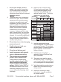
1
45 WATT SOLAR KIT
Model 90599
Installation and service Instructions
Visit our website at: http://www.harborfreight.com
Read this material before using this product.
Failure to do so can result in serious injury.
Save this manual.
Copyright© 2003, 2009 by Harbor Freight Tools®. All rights reserved. No portion of this manual or any
artwork contained herein may be reproduced in any shape or form without the express written consent of
Harbor Freight Tools. Diagrams within this manual may not be drawn proportionally. Due to continuing
improvements, actual product may differ slightly from the product described herein. Tools required for
assembly and service may not be included.
For technical questions or replacement parts, please call 1-800-444-3353.
Revised Manual 11k
not avoided, could result in
minor or moderate injury.
Save This Manual
Keep this manual for the safety
warnings and precautions, installation,
operating, inspection, maintenance and
cleaning procedures. Write the product’s
serial number in the back of the manual
near the assembly diagram (or month
and year of purchase if product has no
number). Keep this manual and the
receipt in a safe and dry place for future
reference.
NOTICE is used to
address practices
not related to personal injury.
CAUTION, without
the safety alert
symbol, is used to address
practices not related to
personal injury.
WARNING Read all safety
warnings and instructions.
Failure to follow the warnings and
instructions may result in electric
shock, fire and/or serious injury.
Save all warnings and
instructions for future reference.
The warnings, precautions,
and instructions discussed in
this instruction manual cannot
cover all possible conditions and
situations that may occur. It must
be understood by the operator that
common sense and caution are
factors which cannot be built into
this product, but must be supplied
by the operator.
Important SAFETY
Information
In this manual, on the labeling,
and all other information
provided with this product:
This is the safety alert
symbol. It is used to alert
you to potential personal
injury hazards. Obey all
safety messages that
follow this symbol to avoid
possible injury or death.
DANGER indicates
a hazardous
situation which, if not
avoided, will result in death or
serious injury.
WARNING
indicates a
hazardous situation which, if
not avoided, could result in
death or serious injury.
CAUTION, used
with the safety
alert symbol, indicates a
hazardous situation which, if
SKU 90599
Installation Precautions
1.
Exercise special caution if working
on roof or another high location.
Keep proper footing and balance at
all times. Follow ladder supplier’s
precautions whenever working near
or on a ladder.
2.
Install all sensitive electrical
components (including wiring
connections, regulator, and
battery) inside a weatherproof
enclosure to prevent electric
shock.
For technical questions, please call 1-800-444-3353.
Page 2
3.
Do not wire multiple panels in
series. If you need to connect two
or more solar panels together, this
work must be done by a qualified
electrician unless they are connected
through a regulator.
4.
This solar panel kit is not designed
for tie-in to a grid. Only a licensed
electrician and a licensed building
contractor can safely design and
implement a grid tie-in system. Any
grid tie-in system must meet all
applicable building and electrical
codes, and must meet standards
established by the area power
company. Improper grid tie-in can
result in electrocution, fire, and other
serious personal injury and property
damage. An incorrectly installed grid
tie-in system can cause feedback
voltage, resulting in electrocution of
electrical utility workers.
5.
Do not stand on or otherwise apply
pressure to panel.
6.
Handle solar panel with care,
edges may be sharp.
7.
Do not focus light on panel.
8.
Install components with enough
space to allow proper cooling.
9.
This product may occasionally
produce more current and/or
voltage than its rated output.
Increase output ratings by 25%
when determining component
required voltage and amperage
ratings. Refer to Section 690-8 of
the National Electrical Code for an
additional multiplying factor of 125
percent (80 percent derating) which
may apply.
SKU 90599
10. Panel must be connected using
UL listed outdoor rated wire of the
correct thickness (gauge) for the
amperage rating and length (see
warning number 9 also). Follow the
guidelines in the chart below:
Maximum Length
Current
in Amps 5'
10'
15'
20'
25'
0-5
6-7
8
10
11-12
15
18
20
22-24
30
40
50
100
150
200
18
18
18
18
16
16
16
14
14
18
16
14
12
10
8
16
14
14
12
16
12
12
10
10
12
10
8
10
8
6
6
4
4
2
Minimum Wire Gauge
11. Install an appropriate charge
controller/regulator to regulate output
and prevent damage. Do not attach
panel to battery or power grid without
proper regulator, inverter, and/or
charge controller.
12. Install and use according to
applicable National Electrical Code
(NEC) standards.
13. This panel is not rated for use as
fire-resistant roofing. If installing on
a roof, install only over a fire resistant
roof covering rated for the application.
14. Verify that installation surface has no
hidden utility lines before drilling or
driving screws.
15. Install only according to these
instructions. Improper installation
can create hazards.
For technical questions, please call 1-800-444-3353.
Page 3
16. Wear ANSI-approved safety goggles
and heavy-duty work gloves during
installation. Do not wear jewelry or
metal watches when working near
solar panels, wiring or batteries.
Service Precautions
1.
a.Dry solar panels and outdoor
wiring thoroughly while wearing
electrically insulated gloves.
17. Handle panel with care. Glass
may break or a sharp edge may be
exposed during movement.
b.Cover all solar panels with an
opaque cover, such as a blanket.
18. Keep installation area clean and well
lit.
19. Install out of reach of children.
20. Keep bystanders out of the area
during installation.
21. Do not install when tired or when
under the influence of drugs or
medication.
c.Disconnect all solar panels.
d.Disconnect all batteries.
2.
Do not service during rain, fog, or
any other wet/humid weather.
3.
Do not stand on or otherwise apply
pressure to panel.
4.
Do not allow children to play with
or near this item or electrical
components.
5.
Inspect at least monthly; do not use
if damaged, parts are loose, water is
found inside the housing, electrical
insulation is cracked or damaged, or
connections are loose.
6.
Maintain product labels and
nameplates. These carry important
safety information. If unreadable or
missing, contact Harbor Freight Tools
for a replacement.
7.
WARNING: Handling the cord on
this product will expose you to lead,
a chemical known to the State of
California to cause cancer, and
birth defects or other reproductive
harm. Wash hands after handling.
(California Health & Safety Code §
25249.5, et seq.)
22. Use in 12 VDC systems only.
Battery Precautions
23. Wear splash-resistant ANSIapproved safety goggles and
electrically insulated gloves while
working near batteries.
24. Use an appropriate charge
controller whenever connected to
battery.
25. Charge, store, and maintain batteries
according to supplier’s instructions.
Before service, maintenance, or
cleaning:
Save these
instructions.
SKU 90599
For technical questions, please call 1-800-444-3353.
Page 4
to children to prevent electric shock.
Build a childproof enclosure if
needed.
Specifications
Rated Output
14.5 V~ / 15 W
(working)
Open Circuit Voltage
23.5 OCV
Adapter Outlets
3, 6, 9 and 12 VDC
Note: Output will decrease as the panel
gets hotter than room temperature
(~70° F). Angle, solar intensity,
cloud cover and other factors will
effect output
3.
Install the charge controller/regulator
and batteries in a weatherproof
enclosure with proper ventilation.
Mounting
1.
Angle the face of the panel toward
true south1 according to the chart that
follows:
Latitude Solar Panel Angle
0-4°
5-20°
21-45°
46-64°
65° or more
Unpacking
When unpacking, make sure that the
item is intact and undamaged. If any parts
are missing or broken, please call Harbor
Freight Tools at 1-800-444-3353 as soon
as possible.
10°
Latitude + 5°
Latitude + 10°
Latitude + 15°
80°
Assembly
6a
Installation
Read the entire Important
Safety Information
section at the beginning of this
manual including all text under
subheadings therein before set
up or use of this product.
Note: For additional information regarding
the parts listed in the following pages,
refer to the Assembly Diagram near
the end of this manual.
Location
1.
Locate the panel where it will receive
full, unobstructed sunlight, especially
during midday. Nearby trees or tall
plants will drop debris, requiring the
panel to be cleaned more frequently.
2.
The installation location for the
panels, charge controller/regulator,
and batteries must be inaccessible
SKU 90599
Slot 3
6b
1.
Slide the Left and Right Triangle
Frame (6a and 6b) into slot 1 and
slot 3 on both ends of the Top Link
Bar (6d) and Bottom Link Bar (6C)
(to form the frame assembly). See
above.
1Angle
towards true north if installed in
southern hemisphere.
For technical questions, please call 1-800-444-3353.
Page 5
6c
6d
4.
Secure the Frame Assembly (6a6d) to its mounting location using
hardware (not supplied) through the
four holes on the bottom of the Left
and Right Triangle Frames (6a &
6b).
5.
Carefully place each Solar Panel (1)
on the front of the Frame Assembly
(6a-6d) so that the bottom of each
panel fits into the slot on the bottom
of the Frame Assembly (6a-6d).
6.
Lock the two eye hooks on the backcenter frame into the two protruding
bolts on the Top Link Bar (6d).
Slot 1
2.
Push the Top Link Bar (6d) down to
slot 2 (to lock the frame assembly).
See above.
3.
Determine where you want to position
the Frame Assembly (6a-6d) making
sure it is facing south (for maximum
sun exposure) with no obstructions
in front of it. The Regulator (2) must
be in a dry, well ventilated location
nearby. If necessary, build a small
structure that guarantees the unit will
stay dry during rain or snow, and,
SKU 90599
provide enough ventilation to allow
the unit to vent and cool properly.
Slot 2
CAUTION: If the unit is to be mounted
on a rooftop, be especially careful
when climbing ladders and walking
on sloped roofs. Additional hardware
may have to be purchased if
For technical questions, please call 1-800-444-3353.
Page 6
permanently mounting the Solar
panels on a rooftop.
Hook-Up Diagram
Regulator (2)
3.
Secure all connections using
terminals, or solder all wire splices to
ensure good connections.
4.
Weatherproof all connections.
Operation
Solar Panels (1)
lead
wires
7.
Connect the two ring connectors at
the end of the lead wires coming
from the Solar Panels (1) to the
Solar Terminals on the Regulator
(2). See FIGURE 1. Be sure to
connect by matching polarities on
the wires and the Regulator (2).
Black (-) is negative and red (+) is
positive. Then, connect the wire
leads so that all of the Solar Panels
(1) are connected to each other and
the Regulator (2) (again, making
sure you are hooking up to the right
polarity on the Regulator). See
Hook-Up Diagram, above.
Note: Performance of the Solar Panels
will vary dependent on site location,
angle of the panels in relation to the
arc of the sun, and available sunlight.
Recharging a Battery
1.
Wiring
Note: Only a licensed electrician and
a licensed building contractor can
safely design and implement a grid
tie-in system. Any grid tie-in system
must meet all applicable building
and electrical codes, and must meet
standards established by the area
power company.
1.
2.
Run wires from the panels, through
weatherproof grommets and into
the enclosure where the charge
controller/regulator is located. Use
wires of the proper size and rating.
Connect to charge controller/regulator
according to controller/regulator’s
instructions.
SKU 90599
To recharge a 12 volt battery (not
included), while paying attention
to the proper polarity (black (-) is
negative and red (+) is positive),
connect the two ring terminals on
the Battery Connector (3) to the
Battery Terminals on the back of
the Regulator (2). See FIGURE
1. Then, connect the black clamp to
the black or negative (-) terminal on
the battery (not included). Finally,
connect the red clamp to the red or
positive (+) terminal on the battery.
Avoid accidental contact of the red
and black battery clamps to each
other.
Note: Do not change the order explained
in number 1 above or electric shock
resulting in serious injury or death
may occur.
2.
Turn on the Regulator. See the On/
Off switch in FIGURE 1 on page 6.
3.
Never leave the battery (not included)
unattended while charging. When
the battery (not included) is fully
charged, the reading on the voltage
display will show “13” or above.
Note: the voltage display will have to
be turned on in order to monitor the
For technical questions, please call 1-800-444-3353.
Page 7
batter voltage. (It is recommended to
leave the voltage display off when not
monitoring the battery voltage since it
consumes energy.) Twelve (12) Volt
batteries should charge to 13 Volts
for a full charge. If the intent is to
stop charging the battery, disconnect
the solar panels from the charge
regulator. Note: The charge regulator
provides “over charge” protection. If
the battery voltage is higher than 14.5
V, the regulator will shut off charge
from solar panel.
4.
Using the 12 Volt Lights and
Accessories.
Note: The Charge Regulator must be in
“ON” position at all times.
1.
If the 12 Volt Lights (4) aren’t
already attached to the sockets on
the end of each Light Wire (7), gently
snap them in.
2.
Plug the other end of the Light
Wire (7) into any one of the 12 Volt
DC outlets on the Regulator (2) as
shown in FIGURE 2.
The Regulator (2) provides the
following protection while charging:
a.Over-discharge Protection: When
the electricity level of the battery
(not included) goes too low (below
11 volts) the Regulator (2) will
automatically shut off the power
output to prevent damage to the
battery (not included). If this occurs,
stop using the battery (not included)
and charge it until the Voltage
display shows 13 volts.
Figure 2
Led
Display
Switch
b.Overcharge Protection: If the
electricity level on the battery (not
included) goes too high (above
14.5 volts) the Regulator (2) will
automatically shut off power input to
prevent damage to the battery (not
included).
c.Overload Protection: If the output
current exceeds 4 amps the fuse
(See FIGURE 1) will blow to prevent
damage to the controller in the
Regulator (2). If this occurs, have a
qualified service technician replace
the fuse.
Note: The On/Off switch of the charge
regulator must be in the “On”
position to activate the three
protection functions mentioned
above.
SKU 90599
12 Volt DC
Socket
Voltage
Display
Controller
Power
Switch
Light Sockets
3.
To turn off the lights, unplug the Light
Wire (7) from the 12 Volt DC outlet
on the Regulator (2). You may plug
in the other 12 Volt Light (4) to either
12 Volt DC outlet.
Note: This system can also be used to
power other small 3 Volt DC, 6 Volt
DC, and 9 Volt DC small appliances.
For technical questions, please call 1-800-444-3353.
Page 8
REV 10k
4.
Plug the appropriate plug on the
Multi Purpose Adapter (5) into the
appliance. The adapter has 3 Volt
DC, 5 Volt DC, 6 Volt DC, 9 Volt DC,
and 12 Volt DC plugs.
5.
Insert the plug on the other end of the
wire attached to the Multi Purpose
Adapter (5) into the appropriate DC
Outlet on the Regulator (2). For
your reference, FIGURE 2 shows the
adapter wire plugged into the 3 Volt
DC outlet.
6.
Operate your appliance.
7.
When finished, unplug the Multi
Purpose Adapter (5) wire plug from
the Regulator (2) and then unplug
the Multi Purpose Adapter (5) from
the appliance.
Servicing
Procedures not specifically
explained in this manual
must be performed only by a
qualified technician.
To prevent
serious injury
from Electric Shock:
Before service, maintenance,
or cleaning:
a.Dry solar panels and outdoor
wiring thoroughly while
wearing electrically insulated
gloves.
b.Cover all solar panels with
an opaque cover, such as a
blanket.
c.Disconnect all solar panels.
d.Disconnect all batteries.
SKU 90599
To prevent serious
injury from electric
shock or cuts:
Do not use damaged solar
panel. If wiring insulation
is damaged or weathered,
glass is cracked, or housing
is opened, have the problem
corrected before further use.
Note: It is normal to see up to 20%
degradation in amorphous silicon
solar panel performance within the
first 6 months before the amorphous
coating stabilizes.
Cleaning
Clean and inspect the solar panel
system MONTHLY, or more
frequently to maintain peak efficiency:
1.
Wear electrically insulated gloves
and ANSI-approved safety goggles.
Dry solar panels and outdoor wiring
thoroughly.
2.
Cover all solar panels with an
opaque cover, such as a blanket.
3.
Disconnect all solar panels and
batteries.
4.
Clean solar panels one at a time with
mild, non-abrasive cleanser and soft
cloth and paper towels. Do not clean
with brushes or abrasive cleaners.
5.
Inspect the general condition of the
solar panel system (panels, batteries,
controllers, and mounting). Check
for loose hardware, wiring insulation
damage or weathering, cracked
glass, open housing, cracked or
broken parts, loose or corroded
contacts, and any other condition that
may affect its safe operation.
For technical questions, please call 1-800-444-3353.
Page 9
6.
Inspect and maintain batteries
according to supplier’s instructions.
Adjustment
To Increase Efficiency:
7.
In the Winter, increase the panel’s
angle by 10°.
8.
In the Summer, decrease the angle
by up to 10°.
9.
In the Spring and Fall, keep the
panel at the angle recommended on
the chart on page 9.
SKU 90599
For technical questions, please call 1-800-444-3353.
Page 10
PLEASE READ THE FOLLOWING CAREFULLY
The manufacturer and/or distributor has provided the parts list and assembly
diagram in this manual as a reference tool only. Neither the manufacturer or
distributor makes any representation or warranty of any kind to the buyer that
he or she is qualified to make any repairs to the product, or that he or she is
qualified to replace any parts of the product. In fact, the manufacturer and/
or distributor expressly states that all repairs and parts replacements should
be undertaken by certified and licensed technicians, and not by the buyer. The
buyer assumes all risk and liability arising out of his or her repairs to the
original product or replacement parts thereto, or arising out of his or her
installation of replacement parts thereto.
Parts List and Assembly Diagram
Part
Description
Q’ty
Part
Description
Q’ty
1
Solar Panel
3
6a
Left Triangle Frame
1
2
Regulator
1
6b
Right Triangle Frame
1
3
Battery Connector
1
6c
Bottom Link Bar
1
4
12 Volt Light
2
6d
Top Link Bar
1
5
Multi-purpose Adapter
1
7
Light Wire
2
7
2
5
Record Product’s Serial Number Here:
4
Note: If product has no serial number, record month and year of purchase instead.
Note: Some parts are listed and shown for illustration purposes only, and are not
available individually as replacement parts.
SKU 90599
For technical questions, please call 1-800-444-3353.
REV 11k
Page 11