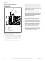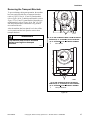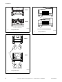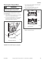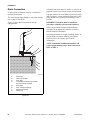
1
Installation
Washer-Extractors
Cabinet Freestanding
Refer to page 7 for Model Identification
CFD23C
33, 40, 55 and 75 Models
CFD23C
CFD24C
CFD24C
18, 25, 30 and 35 Models
CFD25C
100, 135, 165 and 200 Models
CFD
Keep These Instructions for Future Reference.
(If this machine changes ownership, this manual must accompany machine.)
www.alliancelaundry.com
Part No. 9002106ENR4
October 2013
Table of
Contents
Safety Information..............................................................................
Explanation of Safety Messages...........................................................
Important Safety Instructions ...............................................................
Safety Decals ........................................................................................
2
2
2
4
Introduction.........................................................................................
Model Identification .............................................................................
Nameplate Location..............................................................................
Replacement Parts ................................................................................
Customer Service..................................................................................
5
5
7
7
7
Specifications and Dimensions...........................................................
8
Installation...........................................................................................
Dimensional Clearances...................................................................
Machine Foundation ........................................................................
Mechanical Installation.........................................................................
Frame Dimensions and Mounting Bolt Location.............................
Mounting Bolt Installation (If Required)..............................................
Removing the Transport Brackets ........................................................
Removing the Transport Block.............................................................
Drain Connection..................................................................................
Water Connection .................................................................................
Electrical Installation ............................................................................
Electrical Connection............................................................................
Remote Liquid Supply Connection ......................................................
Chemical Injection Supply System ..................................................
Steam Requirements (Steam Heat Option Only)..................................
Supply Programming Table .............................................................
Supply Relay Configuration (No Wiring)........................................
Primary 220 Volt Remote Liquid Supply Connection.....................
Out-of-Balance Switch .........................................................................
Automatic Lubricator............................................................................
Control Function Test ...........................................................................
22
22
23
24
24
36
37
39
40
42
43
56
57
57
58
59
59
59
61
61
62
© Copyright 2013, Alliance Laundry Systems LLC
All rights reserved. No part of the contents of this book may be reproduced or transmitted in any form or by any
means without the expressed written consent of the publisher.
9002106ENR4
© Copyright, Alliance Laundry Systems LLC – DO NOT COPY or TRANSMIT
1
Safety Information
Explanation of Safety Messages
Precautionary statements (“DANGER”,
“WARNING”, and “CAUTION”), followed by
specific instructions, are found in this manual and on
machine decals. These precautions are intended for the
personal safety of the operator, user, servicer, and
those maintaining the machine.
Important Safety Instructions
WARNING
To reduce the risk of fire, electric shock,
serious injury or death to persons when
using your washer, follow these basic
precautions:
W023
DANGER
DANGER indicates the presence of a
hazard that will cause severe personal
injury, death, or substantial property
damage if the danger is ignored.
WARNING
WARNING indicates the presence of a
hazard that can cause severe personal
injury, death, or substantial property
damage if the warning is ignored.
CAUTION
CAUTION indicates the presence of a
hazard that will or can cause minor
personal injury or property damage if the
caution is ignored.
Additional precautionary statements (“IMPORTANT”
and “NOTE”) are followed by specific instructions.
IMPORTANT: The word “IMPORTANT” is used
to inform the reader of specific procedures where
minor machine damage will occur if the procedure
is not followed.
NOTE: The word “NOTE” is used to communicate
installation, operation, maintenance or servicing
information that is important but not hazard
related.
1. Read all instructions before using the washer.
2. Install the washer according the
INSTALLATION instructions. Refer to the
EARTHING (grounding) instructions in the
INSTALLATION manual for the proper earthing
(grounding) of the washer. All connections for
water, drain, electrical power and earthing
(grounding) must comply with local codes and be
made by licensed personnel when required. It is
recommended that the machine be installed by
qualified technicians.
3. Do not install or store the washer where it will be
exposed to water and/or weather.
4. To prevent fire and explosion, keep the area
around machine free from flammable and
combustible products. Do not add the following
substances or textiles containing traces of the
following substances to the wash water: gasoline,
kerosene, waxes, cooking oils, vegetable oils,
machine oils, dry-cleaning solvents, flammable
chemicals, thinners, or other flammable or
explosive substances. These substances give off
vapors that could ignite, explode or cause the
fabric to catch fire by itself.
5. Under certain conditions, hydrogen gas may be
produced in a hot water system that has not been
used for two weeks or more. HYDROGEN GAS
IS EXPLOSIVE. If the hot water system has not
been used for such a period, before using a
washing machine or combination washer-dryer,
turn on all hot water faucets and let the water
flow from each for several minutes. This will
release any accumulated hydrogen gas. The gas
is flammable, do not smoke or use an open flame
during this time.
6. To reduce the risk of an electric shock or fire, DO
NOT use an extension cord or an adapter to
connect the washer to the electrical power
source.
2
© Copyright, Alliance Laundry Systems LLC – DO NOT COPY or TRANSMIT
9002106ENR4
Safety Information
7. Do not allow children to play on or in the washer.
Close supervision of children is necessary when
the washer is used near children. This appliance
is not intended for use by young children or
infirm persons without supervision. Young
children should be supervised to ensure that they
do not play with the appliance. This is a safety
rule for all appliances.
8. DO NOT reach and/or climb into the tub or onto
the washer, ESPECIALLY if the wash drum is
moving. This is an imminently hazardous
situation that, if not avoided, will cause severe
personal injury or death.
9. Never operate the washer with any guards, panels
and/or parts removed or broken. DO NOT bypass
any safety devices or tamper with the controls.
10. Use washer only for its intended purpose,
washing textiles. Never wash machine parts or
automotive parts in the machine. This could
result in serious damage to the basket or tub.
11. Use only low-sudsing, no-foaming types of
commercial detergent. Be aware that hazardous
chemicals may be present. Wear hand and eye
protection when adding detergents and
chemicals. Always read and follow
manufacturer’s instructions on packages of
laundry and cleaning aids. Heed all warnings or
precautions. To reduce the risk of poisoning or
chemical burns, keep them out of the reach of
children at all times (preferably in a locked
cabinet).
12. Do not use fabric softeners or products to
eliminate static unless recommended by the
manufacturer of the fabric softener or product.
13. Always follow the fabric care instructions
supplied by the textile manufacturer.
14. Loading door MUST BE CLOSED any time the
washer is to fill, tumble or spin. DO NOT bypass
the loading door switch by permitting the washer
to operate with the loading door open. Do not
attempt to open the door until the washer has
drained and all moving parts have stopped.
15. Be aware that hot water is used to flush the
supply dispenser. Avoid opening the dispenser lid
while the machine is running.
16. Do not attach anything to the supply dispenser’s
nozzles, if applicable. The air gap must be
maintained.
18. Be sure water connections have a shut-off valve
and that fill hose connections are tight. CLOSE
the shut-off valves at the end of each wash day.
19. Keep washer in good condition. Bumping or
dropping the washer can damage safety features.
If this occurs, have washer checked by a
qualified service person.
20. DANGER: Before inspecting or servicing
machine, power supply must be turned OFF. The
servicer needs to wait for at least 10 minutes after
turning the power OFF and needs to check for
residual voltage with a voltage meter. The
inverter capacitor or EMC filter remains charged
with high voltage for some time after powering
OFF. This is an imminently hazardous situation
that, if not avoided, will cause severe personal
injury or death.
21. Do not repair or replace any part of the washer, or
attempt any servicing unless specifically
recommended in the user-maintenance
instructions or in published user-repair
instructions that the user understands and has the
skills to carry out. ALWAYS disconnect the
washer from electrical, power and water supplies
before attempting any service.
22. Disconnect the power cord by grasping the plug,
not the cord. Replace worn power cords and/or
loose plugs. If the supply cord is damaged, it
must be replaced by a special cord or assembly
available from the service agent.
23. Before the washer is removed from service or
discarded, remove the door to the washing
compartment.
24. Failure to install, maintain, and/or operate this
washer according to the manufacturer’s
instructions may result in conditions which can
produce bodily injury and/or property damage.
NOTE: The WARNINGS and IMPORTANT
SAFETY INSTRUCTIONS appearing in this
manual are not meant to cover all possible
conditions and situations that may occur. Common
sense, caution and care must be exercised when
installing, maintaining, or operating the washer.
Always contact your dealer, distributor, service agent
or the manufacturer on any problems or conditions you
do not understand.
17. Do not operate the machine without the water
reuse plug or water reuse system in place, if
applicable.
9002106ENR4
© Copyright, Alliance Laundry Systems LLC – DO NOT COPY or TRANSMIT
3
Safety Information
Safety Decals
WARNING
This machine must be installed, adjusted,
and serviced by qualified electrical
maintenance personnel familiar with the
construction and operation of this type of
machinery. They must also be familiar
with the potential hazards involved.
Failure to observe this warning may result
in personal injury and/or equipment
damage, and may void the warranty.
Safety decals appear at crucial locations on the
machine. Failure to maintain legible safety decals
could result in injury to the operator or service
technician.
Use manufacturer-authorized spare parts to avoid
safety hazards.
SW004
IMPORTANT: Ensure that the recommended
clearances for inspection and maintenance are
provided. Never allow the inspection and
maintenance space to be blocked.
WARNING
Never touch internal or external steam
pipes, connections, or components.
These surfaces can be extremely hot and
will cause severe burns. The steam must
be turned off and the pipe, connections,
and components allowed to cool before
the pipe can be touched.
SW014
4
© Copyright, Alliance Laundry Systems LLC – DO NOT COPY or TRANSMIT
9002106ENR4
Introduction
Model Identification
Information in this manual is applicable to these
models:
18
HX018PVQM7
HX018PVXM7
HX18PVQM6
HX18PVQM7
HX18PVQU6
HX18PVXM6
HX18PVXM7
HX18PVXU6
NX018BVPA7
NX018BVQA7
NX018BVXA7
NX018BVXM7
NX18BVPA6
NX18BVPA7
NX18BVQA6
NX18BVQA7
NX18BVXA6
NX18BVXA7
NX18BVXM6
NX18BVXM7
SX018BVPA7
SX018BVQA7
SX018BVXA7
SX018BVXM7
SX018PVPA7
SX018PVQM7
SX018PVXM7
SX18BVPA7
SX18BVQA7
SX18BVXA7
SX18BVXM7
SX18PVPA7
SX18PVQM6
SX18PVQM7
SX18PVQU6
SX18PVXM6
SX18PVXM7
SX18PVXU6
UX018PVNA7
UX018PVPA7
UX018PVQA7
UX018PVQM7
UX018PVXA7
UX018PVXM7
UX18PVNA6
UX18PVNA7
UX18PVNU6
UX18PVPA6
UX18PVPA7
UX18PVPU6
UX18PVQA6
UX18PVQA7
UX18PVQM6
UX18PVQM7
UX18PVQU6
UX18PVXA6
UX18PVXA7
UX18PVXM6
UX18PVXM7
UX18PVXU6
HX25PVXU6
SX025PVQM7
SX025PVXM7
SX25PVQM6
SX25PVQM7
SX25PVQU6
SX25PVXM6
SX25PVXM7
SX25PVXU6
UX025PVNA7
UX025PVPA7
UX025PVQA7
UX025PVQM7
UX025PVXA7
UX025PVXM7
UX25PVNA6
UX25PVNA7
UX25PVNU6
UX25PVPA6
UX25PVPA7
UX25PVPU6
UX25PVQA6
UX25PVQA7
UX25PVQM6
UX25PVQM7
UX25PVQU6
UX25PVXA6
UX25PVXA7
UX25PVXM6
UX25PVXM7
UX25PVXU6
25
HX025PVQM7
HX025PVXM7
HX25PVQM6
HX25PVQM7
HX25PVQU6
HX25PVXM6
HX25PVXM7
30
NX030BVPA7
NX030BVQA7
NX030BVXA7
NX030BVXM7
NX30BVPA6
NX30BVPA7
NX30BVQA6
NX30BVQA7
NX30BVXA6
NX30BVXA7
NX30BVXM6
NX30BVXM7
SX030BVPA7
SX030BVQA7
SX030BVXA7
SX030BVXM7
SX30BVPA7
SX30BVQA7
SX30BVXA7
SX30BVXM7
33
SX33BVPA7
SX33BVQA7
SX33BVXA7
SX33BVXM7
UX33PVNA7
UX33PVPA7
UX33PVQA7
UX33PVQM7
UX33PVXA7
UX33PVXM7
35
HX035PVQM7
HX035PVXM7
HX35PVQM6
HX35PVQM7
HX35PVQU6
HX35PVXM6
HX35PVXM7
HX35PVXU6
SX035PVNM7
SX035PVQM7
SX035PVXM7
SX35PVNM7
SX35PVQM6
SX35PVQM7
SX35PVQU6
SX35PVXM6
SX35PVXM7
SX35PVXU6
UX035PVNA7
UX035PVPA7
UX035PVQA7
UX035PVQM7
UX035PVXA7
UX035PVXM7
UX35PVNA6
UX35PVNA7
UX35PVNU6
UX35PVPA6
UX35PVPA7
UX35PVPU6
UX35PVQA6
UX35PVQA7
UX35PVQM6
UX35PVQM7
UX35PVQU6
40
SX40BVPA7
SX40BVQA7
SX40BVXA7
SX40BVXM7
UX40PVNA7
UX40PVPA7
UX40PVQA7
UX40PVQM7
UX40PVXA7
UX40PVXM7
55
HX055PVNU7
HX055PVQU7
HX055PVXU7
HX55PVNU6
HX55PVNU7
HX55PVQU6
HX55PVQU7
HX55PVXU6
HX55PVXU7
SX055PVNU7
SX055PVPU7
SX055PVQU7
SX055PVXU7
SX55PVNU6
SX55PVNU7
SX55PVPU6
SX55PVPU7
SX55PVQU6
SX55PVQU7
SX55PVXU6
SX55PVXU7
UX055PVNU7
UX055PVPU7
UX055PVQU7
UX055PVXF7
UX055PVXU7
UX55PVNU6
UX55PVNU7
UX55PVPU6
UX55PVPU7
75
HX075PVNU7
HX075PVPU7
HX075PVQU7
HX75PVNU6
HX75PVNU7
HX75PVPU7
HX75PVQU6
HX75PVQU7
SX075PVNU7
SX075PVPU7
SX075PVQU7
SX75PVNU6
SX75PVNU7
SX75PVPU7
SX75PVQU6
SX75PVQU7
UX075PVNU7
UX075PVPU7
UX075PVQU7
UX75PVNU6
UX75PVNU7
UX75PVPU6
UX75PVPU7
UX75PVQU6
UX75PVQU7
UX35PVXA6
UX35PVXA7
UX35PVXM6
UX35PVXM7
UX35PVXU6
UX55PVQU6
UX55PVQU7
UX55PVXF6
UX55PVXF7
UX55PVXU6
UX55PVXU7
(continued)
9002106ENR4
© Copyright, Alliance Laundry Systems LLC – DO NOT COPY or TRANSMIT
5
Introduction
(continued)
6
100
HX100
HX100PVNU6
HX100PVNU7
HX100PVPU7
HX100PVQU6
HX100PVQU7
SX100
SX100PVNU6
SX100PVNU7
SX100PVPU7
SX100PVQU6
SX100PVQU7
UX100
UX100PVNU6
UX100PVNU7
UX100PVPU6
UX100PVPU7
UX100PVQU6
UX100PVQU7
135
HX135
HX135PVNU6
HX135PVNU7
HX135PVPU7
HX135PVQU6
HX135PVQU7
SX135
SX135PVNU6
SX135PVNU7
SX135PVPU7
SX135PVQU6
SX135PVQU7
UX135
UX135PVNU6
UX135PVNU7
UX135PVPU6
UX135PVPU7
UX135PVQU6
UX135PVQU7
165
HX165
HX165PVNU6
HX165PVNU7
HX165PVPU7
HX165PVQU6
HX165PVQU7
SX165
SX165PVNU6
SX165PVNU7
SX165PVPU7
SX165PVQU6
SX165PVQU7
UX165
UX165PVNU6
UX165PVNU7
UX165PVPU6
UX165PVPU7
UX165PVQU6
UX165PVQU7
200
HX200
HX200PVNU7
HX200PVPU7
HX200PVQU7
SX200
SX200PVNU7
SX200PVPU7
SX200PVQU7
UX200
UX200PVNU7
© Copyright, Alliance Laundry Systems LLC – DO NOT COPY or TRANSMIT
UX200PVPU7
UX200PVQU7
9002106ENR4
Introduction
Nameplate Location
The nameplate is located at the rear of the machine.
Always provide the machine’s serial number and
model number when ordering parts or when seeking
technical assistance. Refer to Figure 1.
1
1
1
CFD23C
CFD23C
CFD24CCFD24C
CFD25C
CFD25C
18, 25, 30 AND 35 MODELS
1
33, 40, 55 AND 75 MODELS
100, 135, 165 AND 200 MODELS
Nameplate
Figure 1
Replacement Parts
If literature or replacement parts are required, contact
the source from which the machine was purchased or
contact Alliance Laundry Systems at
+1 (920) 748-3950 for the name and address of the
nearest authorized parts distributor.
Customer Service
For technical assistance, contact your local distributor
or contact:
Alliance Laundry Systems
Shepard Street
P.O. Box 990
Ripon, Wisconsin 54971-0990
U.S.A.
www.alliancelaundry.com
Phone: +1 (920) 748-3121
+32 56 41 20 54
Wevelgem, Belgium
9002106ENR4
© Copyright, Alliance Laundry Systems LLC – DO NOT COPY or TRANSMIT
7
Specifications and Dimensions
General Specifications
Model
18
25
30
33
35
40
Overall width
25.98 in.
(660 mm)
25.98 in.
(660 mm)
30.71 in.
(780 mm)
30.71 in.
(780 mm)
30.71 in.
(780 mm)
30.71 in.
(780 mm)
Overall height
40.9 in.
(1038 mm)
40.9 in.
(1038 mm)
47.3 in.
(1202 mm)
53.1 in.
(1348 mm)
47.3 in.
(1202 mm)
53.1 in.
(1348 mm)
Overall depth
28.6 in.
(727 mm)
32.6 in.
(827 mm)
32.1 in.
(816 mm)
29.6 in.
(753 mm)
36.1 in.
(916 mm)
33.6 in.
(853 mm)
Weight and Shipping Information
481 lb.
Net weight †
(218 kg)
525 lb.
(238 kg)
789 lb.
(358 kg)
811 lb.
(368 kg)
800 lb.
(363 kg)
862 lb.
(391 kg)
Overall Dimensions
Net weight ††
520 lb.
(236 kg)
531 lb.
(241 kg)
N/A
N/A
765 lb.
(347 kg)
N/A
Shipping weight †
514 lb.
(233 kg)
564 lb.
(256 kg)
818 lb.
(371 kg)
844 lb.
(383 kg)
849 lb.
(385 kg)
922 lb.
(418 kg)
Shipping weight ††
624 lb.
(283 kg)
639 lb.
(290 kg)
N/A
N/A
1030 lb.
(467 kg)
N/A
Shipping volume
28 ft3
(0.8 m3)
31.8 ft3
(0.9 m3)
45.9 ft3
(1.3 m3)
42.7 ft3
(1.21 m3)
45.9 ft3
(1.3 m3)
45.9 ft3
(1.3 m3)
Cylinder diameter
20.9 in.
(530 mm)
20.9 in.
(530 mm)
25.6 in.
(650 mm)
26.8 in.
(680 mm)
25.6 in.
(650 mm)
26.8 in.
(680 mm)
Cylinder depth
13.0 in.
(330 mm)
17.3 in.
(440 mm)
15.7 in.
(400 mm)
15.7 in.
(400 mm)
19.7 in.
(500 mm)
19.7 in.
(500 mm)
Cylinder volume
2.7 ft3
(73 l)
3.43 ft3
(95 l)
4.66 ft3
(132 l)
5.12 ft3
(145 l)
5.9 ft3
(165 l)
6.39 ft3
(181 l)
Perforation size
0.1 in.
(3 mm)
0.1 in.
(3 mm)
0.1 in.
(3 mm)
0.1 in.
(3 mm)
0.1 in.
(3 mm)
0.1 in.
(3 mm)
11.8 in.
(300 mm)
11.8 in.
(300 mm)
11.8 in.
(300 mm)
15.7 in.
(400 mm)
11.8 in.
(300 mm)
15.7 in.
(400 mm)
10.8 in.
(275 mm)
10.8 in.
(275 mm)
14.8 in.
(375 mm)
18.5 in.
(470 mm)
14.8 in.
(375 mm)
18.5 in.
(470 mm)
Wash Cylinder Information
Door Opening Information
Door opening size
Height of door bottom above
floor
† For Models with A or M in the 8th Position (e.g. *X18PVXA6) or 9th Position (e.g. *X018PVXA7) of the model number
†† For Models with U in the 8th Position (e.g *X18PVXU6) or 9th Position (e.g. *X018PVXU7) of the model number
8
© Copyright, Alliance Laundry Systems LLC – DO NOT COPY or TRANSMIT
9002106ENR4
Specifications and Dimensions
General Specifications
Model
18
25
30
33
35
40
1
1
1
1
1
1
1 HP
(0.75 kW)
1 HP
(0.75 kW)
2 HP
(1.5 kW)
2.95 HP
(2.2 kW)
2 HP
(1.5 kW)
2.95 HP
(2.2 kW)
Drive Train Information
Number of motors in drive train
Drive motor power
Cylinder Speeds
Wash/reverse speed
10-50 RPM
10-50 RPM
10-50 RPM
10-50 RPM
10-50 RPM
10-50 RPM
Distribution/drain speed
85 RPM
82 RPM
85 RPM
85 RPM
74 RPM
85 RPM
Extract speed
250-1000
RPM
250-1000
RPM
250-1000
RPM
250-1000
RPM
250-1000
RPM
250-1000
RPM
Centrifugal Force Data
Wash/reverse centrifugal force
0.03-0.74 Gs 0.03-0.74 Gs
Extract centrifugal force
0.4-0.91 Gs
0.37-0.94 Gs 0.04-0.91 Gs 0.37-0.94 Gs
19-296 Gs
19-296 Gs
23-363 Gs
24-377 Gs
23-363 Gs
24-377 Gs
Standard
Standard
Standard
Standard
Standard
Standard
3/8 in.
(10 mm)
3/8 in.
(10 mm)
3/8 in.
(10 mm)
3/8 in.
(10 mm)
3/8 in.
(10 mm)
3/8 in.
(10 mm)
1
1
1
1
1
1
Balance Detection
Vibration safety switch installed
Direct Steam Heating (Optional)
Steam inlet connection size
Number of steam inlets
9002106ENR4
© Copyright, Alliance Laundry Systems LLC – DO NOT COPY or TRANSMIT
9
Specifications and Dimensions
General Specifications
Model
55
75
100
135
165
200
Overall width
35.4 in.
(900 mm)
41.7 in.
(1060 mm)
47.24 in.
(1200 mm)
47.24 in.
(1200 mm)
51.2 in.
(1300 mm)
51.2 in.
(1300 mm)
Overall height
60.2 in.
(1528 mm)
61.3 in.
(1558 mm)
75.6 in.
(1920 mm)
75.6 in.
(1920 mm)
82.7 in.
(2100 mm)
82.7 in.
(2100 mm)
Overall depth
39.8 in.
(1010 mm)
45.3 in.
(1150 mm)
52.75 in.
(1340 mm)
59.4 in.
(1510 mm)
64.1 in.
(1628 mm)
71.2 in.
(1808 mm)
Overall Dimensions
Weight and Shipping Information
Net weight
1177 lb.
(534 kg)
1612 lb.
(731 kg)
3521 lb.
(1597 kg)
3940 lb.
(1787 kg)
4960 lb.
(2250 kg)
6393 lb.
(2900 kg)
Shipping weight
1287 lb.
(584 kg)
1722 lb.
(781 kg)
3741 lb.
(1697 kg)
4160 lb.
(1887 kg)
5181 lb.
(2350 kg)
6614 lb.
(3000 kg)
Shipping volume
53 ft3
(1.5 m3)
74 ft3
(2.1 m3)
116.5 ft3
(3.3 m3)
131 ft3
(3.7 m3)
155 ft3
(4.4 m3)
218 ft3
(6.17 m3)
Cylinder diameter
29.5 in.
(750 mm)
33.5 in.
(850 mm)
38.6 in.
(980 mm)
38.6 in.
(980 mm)
43.1 in.
(1095 mm)
43.1 in.
(1095 mm)
Cylinder depth
20.9 in.
(530 mm)
21.1 in.
(537 mm)
23.5 in.
(597 mm)
30.5 in.
(775 mm)
30.5 in.
(775 mm)
37.7 in.
(957 mm)
Cylinder volume
8.27 ft3
(234 l)
10.76 ft3
(304 l)
15.92 ft3
(455 l)
20.66 ft3
(575 l)
25.8 ft3
(730 l)
31.748 ft3
(900 l)
Perforation size
0.1 in.
(3 mm)
0.1 in.
(3 mm)
0.1 in.
(3 mm)
0.1 in.
(3 mm)
0.1 in.
(3 mm)
0.1 in.
(3 mm)
Door opening size
15.7 in.
(400 mm)
15.7 in.
(400 mm)
19.7 in.
(500 mm)
19.7 in.
(500 mm)
24.5 in.
(622 mm)
24.5 in.
(622 mm)
Height of door bottom above
floor
20.9 in.
(530 mm)
22.2 in.
(565 mm)
25.1 in.
(638 mm)
25.1 in.
(638 mm)
23.7 in.
(603 mm)
23.7 in.
(603 mm)
Wash Cylinder Information
Door Opening Information
10
© Copyright, Alliance Laundry Systems LLC – DO NOT COPY or TRANSMIT
9002106ENR4
Specifications and Dimensions
General Specifications
Model
55
75
100
135
165
200
1
1
1
1
1
1
4 HP
(3 kW)
5.4 HP
(4 kW)
7.4 HP
(5.5 kW)
10 HP
(7.5 kW)
15 HP
(11 kW)
20 HP
(15 kW)
Drive Train Information
Number of motors in drive train
Drive motor power
Cylinder Speeds
Wash/reverse speed
10-50 RPM 10-50 RPM 10-50 RPM 10-50 RPM 10-50 RPM 10-50 RPM
Distribution/drain speed
69 RPM
65 RPM
61 RPM
61 RPM
100 RPM
80 RPM
Extract speed
250-1000
RPM
250-1000
RPM
250-800
RPM
250-800
RPM
250-750
RPM
250-750
RPM
Wash/reverse centrifugal force
0.04-1.05
Gs
0.05-1.19
Gs
0.06-1.37
Gs
0.06-1.37
Gs
0.06-1.52
Gs
0.06-1.52
Gs
Extract centrifugal force
26-418 Gs 30-475 Gs 34-350 Gs 34-350 Gs
34-350 Gs
34-350 Gs
Centrifugal Force Data
Balance Detection
Vibration safety switch installed
Standard
Standard
Standard
Standard
Standard
Standard
1/2 in.
(13 mm)
1/2 in.
(13 mm)
1/2 in.
(13 mm)
1/2 in.
(13 mm)
3/4 in.
(19 mm)
3/4 in.
(19 mm)
1
1
1
1
1
1
Direct Steam Heating (Optional)
Steam inlet connection size
Number of steam inlets
9002106ENR4
© Copyright, Alliance Laundry Systems LLC – DO NOT COPY or TRANSMIT
11
Specifications and Dimensions
8.66 in.
(220 mm)
10.8 in.
(275 mm)
39.8 in. (1011 mm)
40.87 in. (1038 mm)
11
1.3 in.
(33 mm)
2.56 in.
(65 mm)
1.18 in.
(30 mm)
1.3 in.
(33 mm)
2.56 in.
(65 mm)
20.87 in. (530 mm)
25.98 in. (660 mm)
18: 23.23 in. (590 mm)
25: 27.17 in. (690 mm)
18: 28.62 in. (727 mm)
25: 32.56 in. (827 mm)
CFD558N
8.9 in. (226 mm)
5.94 in. (151 mm)
2.95 in. (75 mm)
CFD558N
1
2
3
4
1.18 in.
(30 mm)
CFD777N
CFD777N
5
10
6
9
8
4.3 in.
(109 mm)
7.09 in. (180 mm)
25.98 in. (660 mm)
2.76 in. (70 mm)
27.41 in. (696.2 mm)
34.92 in. (887 mm)
31.14in. (791 mm)
29.41 in. (747 mm)
19.1 in. (485 mm)
7
1.73 in.
(44 mm)
CFD528N
18 AND 25 POUND CAPACITY MODELS
CFD528N
1
2
3
4
5
6
Fill and Supply Ventilation
Cold Water Inlet (Required)
External Liquid Supply Inlets
Hot Water Inlet (Required)
Ventilation Tub
Main Switch
7
8
9
10
11
Electrical Power Input
Drain Outlet
Steam Connection Input (Optional)
Cold Water Inlet (Required)
Flushing Supply Dispenser
Figure 2
12
© Copyright, Alliance Laundry Systems LLC – DO NOT COPY or TRANSMIT
9002106ENR4
Specifications and Dimensions
8.7 in.
(220 mm)
3.5 in.
(88 mm)
47.3 in.
(1202 mm)
46.3 in.
(1175 mm)
18.7 in.
(475 mm)
25.5 in.
(648 mm)
2.6 in.
(66 mm)
2.6 in.
(66 mm)
30.7 in.
(780 mm)
29.9 in. (760 mm)
32.1 in. (816 mm)
13.1 in.
(332 mm)
10.5 in.
(267 mm)
7.95 in.
(202 mm)
1
2
8
7.9 in.
(200 mm)
6.1 in.
(155 mm)
3
4
7
36.4 in.
(924 mm)
5
1.38 in.
(35 mm)
37.95 in.
(964 mm)
7.87 in.
(200 mm)
33.4 in.
(849 mm)
2.76 in.
(70 mm)
6
CFD778N
30 POUND CAPACITY MODELS
CFD778N
1
2
3
4
Hot Water Connections .75 in. (19 mm)
Cold Water Inlet (required) .75 in. (19 mm)
Power Input
Emergency Stop Button
5
6
7
8
Ventilation Tub
Drain Outlet
Cold Water Inlet (required) .75 in. (19 mm)
Fill and Supply Ventilation
Figure 3
9002106ENR4
© Copyright, Alliance Laundry Systems LLC – DO NOT COPY or TRANSMIT
13
Specifications and Dimensions
3.46 in.
(88 mm)
18.5 in. (470 mm)
53.07 in. (1348 mm)
8.66 in.
(220 mm)
26.77 in. (680 mm)
1.97 in.
(50 mm)
1.97 in.
(50 mm)
30.71 in. (780 mm)
1.34 in.
(34 mm)
26.18 in. (665 mm)
29.65 in. (753 mm)
CFD779N
CFD779N
13.07 in. (332 mm)
10.51 in. (267 mm)
7.95 in. (202 mm)
4.13 in. (105 mm)
1
2
4
1.34 in.
(34 mm)
CFD780N
CFD780N
3
5
6
7
10
1.38 in.
(35 mm)
4.3 in.
(109 mm)
7.28 in. (185 mm)
39.96 in. (1015 mm)
44.9 in. (1141 mm)
43.6 in. (1108 mm)
41.96 in. (1066 mm)
27.7 in. (704 mm)
8
9
6.69 in. (170 mm)
CFD539N
CFD539N
33 POUND CAPACITY
MODELS
1
2
3
4
5
Fill and Supply Ventilation
External Liquid Supply Inlets
Cold Water Inlet (Required)
Cold Water Inlet (Required)
Hot Water Inlet (Required)
6
7
8
9
10
Connection Clamps
Ventilation Tub
Electrical Power Inputs
Drain Valve
Steam Connection Input (Optional)
Figure 4
14
© Copyright, Alliance Laundry Systems LLC – DO NOT COPY or TRANSMIT
9002106ENR4
Specifications and Dimensions
11
8.66 in.
(220 mm)
14.76 in.
(375 mm)
47.32 in. (1202 mm)
46.3 in. (1176 mm)
3.46 in.
(88 mm)
1.34 in.
(34 mm)
2.6 in.
(66 mm)
1.34 in.
(34 mm)
2.6 in.
(66 mm)
25.51 in. (648 mm)
30.71 in.(780 mm)
CFD561N
30.12 in. (765 mm)
CFD561N
1.44 in.
(36.5 mm)
36.06 in. (916 mm)
13.07 in. (332 mm)
10.51 in. (267 mm)
7.95 in. (202 mm)
4.13 in. (105 mm)
9
1.44 in.
(36.5 mm)
CFD781N
CFD781N
1
3
2
10
4
5
8
6
4.3 in.
(109.2 mm)
7
7.87 in.
(200 mm)
33.19 in. (843 mm)
2.75 in. (70 mm)
38.11 in. (968 mm)
36.81 in. (935 mm)
35.16 in. (893 mm)
20.87 in. (530 mm)
1.38 in (35 mm)
2.36 in.
(60 mm)
CFD529N
CFD529N
35 POUND CAPACITY MODELS
1
2
3
4
5
6
Fill and Supply Ventilation
Hot Water Inlet (Required)
Cold Water Inlet (Required)
Main Switch
Ventilation Tub
Electrical Power Input
7
8
9
10
11
Drain Outlet
Steam Connection Input (Optional)
External Liquid Supply Inlets
Cold Water Inlet (Required)
Flushing Supply Dispenser
Figure 5
9002106ENR4
© Copyright, Alliance Laundry Systems LLC – DO NOT COPY or TRANSMIT
15
Specifications and Dimensions
3.46 in.
(88 mm)
18.6 in. (470 mm)
53.07 in. (1348 mm)
8.66 in.
(220 mm)
1.97 in.
(50 mm)
26.77 in. (680 mm)
1.97 in.
(50 mm)
30.71 in. (780 mm)
1.34 in.
(34 mm)
30.12 in. (765 mm)
33.58 in. (853 mm)
CFD782N
CFD782N
13.07 in. (332 mm)
10.51 in. (267 mm)
7.95 in. (202 mm)
4.13 in. (105 mm)
1
2
4
1.34 in.
(34 mm)
CFD783N
CFD783N
3
5
6
10
7
1.38 in.
(35 mm)
4.3 in.
(109 mm)
7.28 in. (185 mm)
39.96 in. (1015 mm)
44.9 in. (1141 mm)
43.6 in. (1108 mm)
41.97 in. (1066 mm)
27.7 in. (704 mm)
8
9
6.69 in. (170 mm)
CFD539N
CFD539N
40 POUND CAPACITY
MODELS
1
2
3
4
5
Fill and Supply Ventilation
External Liquid Supply Inlets
Cold Water Inlet (Required)
Cold Water Inlet (Required)
Hot Water Inlet (Required)
6
7
8
9
10
Connection Clamps
Ventilation Tub
Electrical Power Inputs
Drain Valve
Steam Connection Input (Optional)
Figure 6
16
© Copyright, Alliance Laundry Systems LLC – DO NOT COPY or TRANSMIT
9002106ENR4
Specifications and Dimensions
5
39.76 in.
(1010 mm)
60.16 in.
(1528 mm)
59 in.
(1499 mm)
33.8 in.
(859 mm)
20.86 in.
(530 mm)
29.13 in.
(740 mm)
32.68 in.
(830 mm)
35.43 in.
(900 mm)
4 in.
(102 mm)
CFS470N
CFD562N
CFS470N
CFD562N
3.6 in.
(91 mm)
10 in.
(254 mm)
9.9 in.
(252 mm)
2
6.2 in.
(158 mm)
3
4
3.9 in.
(99 mm)
1
6
7.5 in.
(191 mm)
54.7 in.
(1389 mm)
11
8
50.5 in.
(1283 mm)
7
1.4 in.
(36 mm)
28.4 in.
(721 mm)
6.5 in.
(165 mm)
6.5 in.
(165 mm)
9
10
4.1 in.
4.1 in. (104 mm)
(104 mm)
CFS471N
CFS471N
55 POUND CAPACITY MODELS
1
2
3
4
5
6
Fill and Supply Ventilation
Cold Water Inlet (Required)
Hot Water Inlet (Required)
Cold Water Inlet (Required)
Flushing Supply Dispenser
External Liquid Supply Inlets
7
8
9
10
11
Electrical Power Input
External Supply Signal Input
Drain Outlet
Reuse Drain Outlet (Optional)
Steam Connection Input (Optional)
Figure 7
9002106ENR4
© Copyright, Alliance Laundry Systems LLC – DO NOT COPY or TRANSMIT
17
Specifications and Dimensions
5
45.3 in.
(1150 mm)
61.34 in.
(1558 mm)
60.3 in.
(1532 mm)
33.6 in.
(853 mm)
22.24 in.
(565 mm)
4 in.
(102 mm)
34.05 in.
(865 mm)
CFD563N
41.73 in.
(1060 mm)
37.8 in.
(960 mm)
19.2 in.
(488 mm)
CFD563N
CFS473N
CFS473N
14.4 in.
(366 mm)
9.7 in.
(246 mm)
2
9 in.
(229 mm)
3 4
3.7 in.
(94 mm)
1
6.9 in.
(175 mm)
6
55.4 in.
(1407 mm)
7
11
51.77 in.
(1315 mm)
8
1.7 in.
(43 mm)
10
22.9 in.
(582 mm)
6.7 in.
(170 mm)
9
4.1 in.
(104 mm)
CFS474N
CFS474N
4.1 in.
(104 mm)
1
2
3
4
5
6
Fill and Supply Ventilation
Cold Water Inlet (Required)
Hot Water Inlet (Required)
Cold Water Inlet (Required)
Flushing Supply Dispenser
External Liquid Supply Inlets
75 POUND CAPACITY MODELS
7
Electrical Power Input
8
External Supply Signal Input
9
Drain Outlet
10
Reuse Drain Outlet (Optional)
11
Steam Connection Input (Optional)
Figure 8
18
© Copyright, Alliance Laundry Systems LLC – DO NOT COPY or TRANSMIT
9002106ENR4
Specifications and Dimensions
100: 52.75 in. (1340 mm)
135: 59.4 in. (1510 mm)
6
75.6 in.
(1920 mm)
37.8 in.
(960 mm)
25.1 in.
(638 mm)
40.7 in.
(1034 mm)
47.24 in.
(1200 mm)
CFD564N
CFD564N
100: 39.76 in.
(1010 mm)
11.9 in.
(303 mm)
135: 46.5 in.
(1180 mm)
9.2 in.
(233 mm)
4.4 in.
(113 mm)
3.3 in.
(83 mm)
4 in.
(102 mm)
6.4 in.
(162 mm)
2
3 5
2 in.
(51 mm)
10.1 in.
(257 mm)
13.5 in.
(342 mm)
8.7 in.
(222 mm)
CFS784N
CFD784N
6.8 in.
(173 mm)
1
4
19.1 in.
(486 mm)
9
7
13
12
8
10
27.6 in.
(701 mm)
8.3 in.
(210 mm)
11
1
2
3
4
5
6
7
8.3 in.
(210 mm)
7 in.
(177.5 mm)
CFS785N
100 AND 135 POUND CAPACITY MODELS
Fill and Supply Ventilation
8
Electrical Power Input
Cold Water Inlet (Required)
9
External Supply Signal Input
Hot Water Inlet (Required)
10
Drain Outlet
Cold Water Inlet (Required)
11
Reuse Drain Outlet (Optional)
Cold Water Inlet (Required)
12
Steam Connection Input (Optional)
Flushing Supply Dispenser
13
Service Power Disconnect
External Liquid Supply Inlets
Figure 9
9002106ENR4
© Copyright, Alliance Laundry Systems LLC – DO NOT COPY or TRANSMIT
19
Specifications and Dimensions
64.1 in.
(1628 mm)
6
82.7 in.
(2100 mm)
39.1 in.
(992.5 mm)
23.7 in.
(603 mm)
44.8 in.
(1138 mm)
51.2 in.
(1300 mm)
CFD564N
CFD564N
16.1 in.
(408 mm)
12.7 in.
(323 mm)
46.7 in.
(1185 mm)
9.8 in.
(248 mm)
CFD786N
CFD786N
6.8 in.
(173 mm)
3.19 in.
(81 mm)
4.6 in.
(117 mm)
2
7 in.
(177 mm)
10.3 in.
(262 mm)
2 in.
(51 mm)
3 5
10.24 in.
(257 mm)
1
9.3 in.
(237 mm)
19.1 in.
(486 mm)
4
9
7
13
12
8
10
35.4 in.
(898.5 mm)
10.2 in.
(260 mm)
11
1
2
3
4
5
6
7
Fill and Supply Ventilation
Cold Water Inlet (Required)
Hot Water Inlet (Required)
Cold Water Inlet (Required)
Cold Water Inlet (Required)
Flushing Supply Dispenser
External Liquid Supply Inlets
10.2 in.
(260 mm)
6.9 in.
(174 mm)
CFD785N
165 POUND CAPACITY MODELS
8
Electrical Power Input
9
External Supply Signal Input
10
Drain Outlet (Standard)
11
Dual Drain Outlet (Optional)
12
Steam Connection Input (Optional)
13
Service Power Disconnect
Figure 10
20
© Copyright, Alliance Laundry Systems LLC – DO NOT COPY or TRANSMIT
9002106ENR4
Specifications and Dimensions
6
2.22 in.
(56.5 mm)
82.7 in.
(2100 mm)
39 in.
(992.5 mm)
23.7 in.
(603 mm)
1.73 in.
(44 mm)
3.19 in.
(81 mm)
44.8 in.
(1138 mm)
10.71 in.
(272 mm)
3.19 in.
(81 mm)
51.18 in.
(1300 mm)
53.74 in.
(1365 mm)
71.18 in.
(1808 mm)
1.73 in.
(44 mm)
57.2 in.
(1453 mm)
1.04 in.
(26.5 mm)
CFD534N
CFD565N
CFD565N
CFD534N
16.06 in.
(408 mm)
12.72 in.
(323 mm)
9.76 in.
(248 mm)
6.81 in.
(173 mm)
6.67 in.
(169.5 mm)
23
10.12 in.
(257 mm)
19.13 in.
(486 mm)
10.31 in.
(262 mm)
5
9.33 in.
(237 mm)
7 in.
(177 mm)
4.61 in.
(117 mm)
7 4
1
9
8
13
3.19 in.
(81 mm)
10
12
35.37 in.
(898.5 mm)
6.85 in.
(174 mm)
10.23 in.
(260 mm)
1
2
3
4
5
6
7
Fill and Supply Ventilation
Cold Water Inlet (Required)
Hot Water Inlet (Required)
Cold Water Inlet (Required)
Cold Water Inlet (Required)
Flushing Supply Dispenser
External Liquid Supply Inlets
11
10.23 in.
(260 mm)
CFD535N
200 POUND CAPACITY MODELS
8
Electrical Power Input
9
External Supply Signal Input
10
Drain Outlet (Standard)
11
Dual Drain Outlet (Optional)
12
Steam Connection Input (Optional)
13
Service Power Disconnect
Figure 11
9002106ENR4
© Copyright, Alliance Laundry Systems LLC – DO NOT COPY or TRANSMIT
21
Installation
Dimensional Clearances
Table 1 shows recommended minimum clearances on
all sides of the machine.
Recommended Minimum Clearances
Model
18
25
30
33
35
40
55
75
100
135
165
200
Minimum rear
clearance
23.6 in.
23.6 in.
23.6 in.
23.6 in.
23.6 in.
23.6 in.
23.6 in. 23.6 in. 23.6 in. 23.6 in. 23.6 in. 23.6 in.
(600 mm) (600 mm) (600 mm) (600 mm) (600 mm) (600 mm) (600 mm) (600 mm) (600 mm) (600 mm) (600 mm) (600 mm)
Minimum
clearance between
machine and wall
6 in.
6 in.
6 in.
6 in.
6 in.
6 in.
6 in.
6 in.
6 in.
6 in.
6 in.
6 in.
(150 mm) (150 mm) (150 mm) (150 mm) (150 mm) (150 mm) (150 mm) (150 mm) (150 mm) (150 mm) (150 mm) (150 mm)
Minimum
clearance between
machines (side)
1.2 in.
(30 mm)
Minimum front
clearance (door
swing)
16.5 in.
16.5 in.
21 in.
16.5 in.
21 in.
21 in.
21 in.
26 in.
26 in.
16.5 in.
26 in.
26 in.
(419 mm) (419 mm) (419 mm) (533 mm) (419 mm) (533 mm) (533 mm) (533 mm) (660 mm) (660 mm) (660 mm) (660 mm)
1.2 in.
1 in.
1.2 in.
(30 mm) (25.4 mm) (30 mm)
1.2 in.
(30 mm)
1.2 in.
(30 mm)
1.2 in.
1.2 in.
(30 mm) (30 mm)
1.2 in.
1.2 in.
1.2 in.
1.2 in.
(30 mm) (30 mm) (30 mm) (30 mm)
Table 1
22
© Copyright, Alliance Laundry Systems LLC – DO NOT COPY or TRANSMIT
9002106ENR4
Installation
Machine Foundation
The standard installation does not require anchoring
unless mandated by state or local codes.
Thoroughness of detail must be stressed with all
foundation work to ensure a stable unit installation,
eliminating possibilities of excessive vibration during
extract.
Static and dynamic loads on the floor or foundation are
shown in Table 2.
Table 2 can be used as a reference when designing
floors and foundations.
CAUTION
If installing a foundation and pad, prepare a form for
the above-ground portion of the foundation. Verify
that the top of the foundation is level. The height of the
foundation and pad must not exceed 8 inches
(203 mm) above the existing floor.
Ensure that the machine is installed on a
level floor of sufficient strength and that
the recommended clearances for
inspection and maintenance are provided.
Never allow the inspection and
maintenance space to be blocked.
W488
The machine must be placed on a smooth level surface
so that the entire base of the machine is supported and
rests on the mounting surface.
IMPORTANT: Mounting bolts MUST be used for
installation on the 18, 25 and 35 pound models
equipped with steam heat and models installed on
metal base frames. Refer to Mounting Bolt
Installation.
Floor Load Data
Model
18
25
30
33
35
40
55
75
100
135
165
200
Kinetic Energy of the
Cylinder, (N/m)
1386
1730
2592
2736
3240
4105
6640
12404
18361
23257
29581
29581
Dynamic Bottom
Load, (N/Hz)
550/16 538/16 1100/16 1010/16 1450/16 1090/16 2300/15 2340/15 2960/13 3900/13 4960/13 6100/13
Table 2
9002106ENR4
© Copyright, Alliance Laundry Systems LLC – DO NOT COPY or TRANSMIT
23
Installation
Mechanical Installation
Frame Dimensions and Mounting Bolt
Location
IMPORTANT: Drawings are not to scale.
26 in.
(660 mm)
2.17 in.
(55 mm)
22.05 in.
(560 mm)
2.17 in.
(55 mm)
3.43 in.
(87 mm)
26.38 in.
(670 mm)
19.1 in.
(485 mm)
18 POUND CAPACITY MODELS
3.43 in.
(87 mm)
CFD793N
CFD793N
Figure 12
24
© Copyright, Alliance Laundry Systems LLC – DO NOT COPY or TRANSMIT
9002106ENR4
Installation
25.98 in.
(660 mm)
2.17 in.
(55 mm)
25.98 in.
(660 mm)
30.31 in.
(770 mm)
2.17 in.
(55 mm)
3.43 in.
(87 mm)
19.13 in.
(486 mm)
3.43 in.
(87 mm)
CFD794N
25 POUND CAPACITY MODELS
CFD794N
Figure 13
9002106ENR4
© Copyright, Alliance Laundry Systems LLC – DO NOT COPY or TRANSMIT
25
Installation
1.44 in.
(36.5 mm)
29.06 in.
(738 mm)
26.18 in.
(665 mm)
0.71 in.
(18 mm)
1.44 in.
(36.5 mm)
2.60 in.
(66 mm)
25.51 in.
(648 mm)
2.60 in.
(66 mm)
30.71 in.
(780 mm)
30 POUND CAPACITY MODELS
CFD552N
CFD552N
Figure 14
26
© Copyright, Alliance Laundry Systems LLC – DO NOT COPY or TRANSMIT
9002106ENR4
Installation
1.34 in.
(34 mm)
1.97 in.
(50 mm)
26.77 in.
(680 mm)
28.86 in.
(733 mm)
26.18 in.
(665 mm)
0.87 in.
(22 mm)
1.34 in.
(34 mm)
1.97 in.
(50 mm)
30.71 in.
(780 mm)
CFD553N
33 POUND CAPACITY MODELS
CFD553N
Figure 15
9002106ENR4
© Copyright, Alliance Laundry Systems LLC – DO NOT COPY or TRANSMIT
27
Installation
30.7 in.
(780 mm)
1.77 in.
(45 mm)
30.12 in.
(765 mm)
1.77 in.
(45 mm)
2.6 in.
(66 mm)
33 in.
(838 mm)
25.5 in.
(648 mm)
2.6 in.
(66 mm)
CFD795N
35 POUND CAPACITY MODELS
CFD795N
Figure 16
28
© Copyright, Alliance Laundry Systems LLC – DO NOT COPY or TRANSMIT
9002106ENR4
Installation
1.34 in.
(34 mm)
32.8 in.
(833 mm)
30.12 in.
(765 mm)
0.87 in.
(22 mm)
1.34 in.
(34 mm)
1.97 in.
(50 mm)
26.77 in.
(680 mm)
1.97 in.
(50 mm)
CFD554N
30.71 in.
(780 mm)
40 POUND CAPACITY MODELS
CFD554N
Figure 17
9002106ENR4
© Copyright, Alliance Laundry Systems LLC – DO NOT COPY or TRANSMIT
29
Installation
35.43 in.
(900 mm)
1.4 in.
(35 mm)
32.68 in.
(830 mm)
1.4 in.
(35 mm)
3.18 in.
(81 mm)
35.4 in.
(900 mm)
29.05 in.
(738 mm)
3.18 in.
(81 mm)
CFD788N
55 POUND CAPACITY MODELS
CFD788N
Figure 18
30
© Copyright, Alliance Laundry Systems LLC – DO NOT COPY or TRANSMIT
9002106ENR4
Installation
41.73 in.
(1060 mm)
1.57 in.
(40 mm)
37.8 in.
(960 mm)
1.57 in.
(40 mm)
3.8 in.
(97.5 mm)
40.94 in.
(1040 mm)
34.05 in.
(865 mm)
3.8 in.
(97.5 mm)
CFD788N
75 POUND CAPACITY MODELS
CFD789N
Figure 19
9002106ENR4
© Copyright, Alliance Laundry Systems LLC – DO NOT COPY or TRANSMIT
31
Installation
47.24 in.
(1200 mm)
1.77 in.
(45 mm)
39.76 in.
(1010 mm)
43.3 in.
(1100 mm)
1.77 in.
(45 mm)
3.27 in.
(83 mm)
40.71 in.
(1034 mm)
3.27 in.
(83 mm)
CFD788N
100 POUND CAPACITY MODELS
CFD790N
Figure 20
32
© Copyright, Alliance Laundry Systems LLC – DO NOT COPY or TRANSMIT
9002106ENR4
Installation
47.24 in.
(1200 mm)
1.77 in.
(45 mm)
46.45 in.
(1180 mm)
1.77 in.
(45 mm)
3.27 in.
(83 mm)
50 in.
(1270 mm)
40.71 in.
(1034 mm)
3.27 in.
(83 mm)
CFD791N
135 POUND CAPACITY MODELS
CFD791N
Figure 21
9002106ENR4
© Copyright, Alliance Laundry Systems LLC – DO NOT COPY or TRANSMIT
33
Installation
1.7 in.
(44 mm)
51.2 in.
(1300 mm)
50.12 in.
(1273 mm)
1.7 in.
(44 mm)
3.18 in.
(81 mm)
44.8 in.
(1138 mm)
3.18 in.
(81 mm)
CFD792N
165 POUND CAPACITY MODELS
CFD792N
Figure 22
34
© Copyright, Alliance Laundry Systems LLC – DO NOT COPY or TRANSMIT
9002106ENR4
Installation
53.74 in.
(1365 mm)
57.2 in.
(1453 mm)
1.73 in.
(44 mm)
1.73 in.
(44 mm)
3.19 in.
(81 mm)
44.8 in.
(1138 mm)
3.19 in.
(81 mm)
51.18 in.
(1300 mm)
CFD555N
200 POUND CAPACITY MODELS
CFD555N
Figure 23
9002106ENR4
© Copyright, Alliance Laundry Systems LLC – DO NOT COPY or TRANSMIT
35
Installation
Mounting Bolt Installation
(If Required)
3. Put bolts through the machine in the anchors and
fasten them. For the 18, 25, 30, and 35 models,
the diameter of the bolt must be minimum 1/2-13
or 12 mm; for the 33, 40, 55, 75, 100, 135, 165
and 200 models, the diameter of the bolt must be
minimum 5/8-11 or 16 mm.
1
2
4. To level machine, fill the spaces between the
machine base and floor with machinery grout.
Grout completely under all frame members.
Remove front and rear panels to gain access to all
frame members. Force grout under the machine
base until all voids are filled.
3
5. Allow machine grout to set, but not cure.
6. Remove the spacers carefully, allowing the
machine to settle into the wet grout.
6 in.
(152 mm)
7. Position washers and locknuts on machinery
anchor bolts and finger-tighten to machine base.
CFS485N
4
CFS485N
1
2
3
4
Base Frame
Bolt
Washer
Anchor Bolt/Plug
8. After the grout is completely cured, tighten the
locknuts by even increments – one after the
other – until all are tightened evenly and the
machine is fastened securely to the floor.
9. Remove the four red transport brackets which
secure the moving components of the machine
during shipping. Refer to Figures 25, 27 and 28
for typical transport bracket locations.
Figure 24
After the concrete has cured and the anchors are
installed, proceed as follows:
1. Place the machine adjacent to the foundation. Do
not attempt to move it by pushing on the sides.
Always insert a pry bar or other device under the
bottom of the frame of the washer-extractor to
move it.
2. Place the machine carefully over the anchors.
36
© Copyright, Alliance Laundry Systems LLC – DO NOT COPY or TRANSMIT
9002106ENR4
Installation
Removing the Transport Brackets
To prevent damage during transportation, the machine
has been equipped with four red transport brackets
(refer to Figure 25 for 18, 25 and 35 pound models;
refer to Figure 26 for 33 and 40 pound models; refer to
Figure 27 for 55 and 75 pound models [depending on
model number]; refer to Figure 28 for 100, 135, 165
and 200 pound models) to eliminate every possible
movement of the tub.
After the machine has been placed level, take off the
service panels and the back panel to remove these
transport brackets.
1
WARNING
CFD34N
CFD34N
18, 25, 30 AND 35 MODELS WITH A OR M IN THE 8TH
POSITION (E. G. *X18PVXM6) OR 9TH POSITION
(E. G. *X018PVXM7) OF THE MODEL NUMBER
The machine must never be activated
before removing these transport
brackets.
1
Panel Braces
W489
1
CFD65N
CFD65N
18, 25 AND 35 MODELS WITH U IN THE 8TH
POSITION (E. G. *X18PVXU6) OR 9TH POSITION
(E. G. *X018PVXU7) OF THE MODEL NUMBER
1
Transport Brackets
Figure 25
9002106ENR4
© Copyright, Alliance Laundry Systems LLC – DO NOT COPY or TRANSMIT
37
Installation
FRONT
FRONT
1
1
1
REAR
REAR
1
1
33 AND 40 MODELS
1
CFD543N
1
CFS488N
100, 135, 165 AND 200 MODELS
Transport Brackets
CFS488N
1
Figure 26
Transport Brackets
Figure 28
FRONT
1
REAR
CFS487N
55 AND 75 MODELS
CFS487N
1
Transport Brackets
Figure 27
38
© Copyright, Alliance Laundry Systems LLC – DO NOT COPY or TRANSMIT
9002106ENR4
Installation
Removing the Transport Block
3. For 18 and 30 pound models, remove the panel
braces. Refer to Figure 25.
WARNING
4. For 33 and 40 pound models, remove the
transport brackets. Refer to Figure 26.
The machine must never be activated
before removing the transport block.
W618
To prevent damage during transportation, machine has
been equipped with a transport block. To remove,
proceed as follows:
FRONT
1. After machine has been placed on level ground,
remove service panels and back panel.
1
1
2. For 18 and 30 pound models, at rear of machine,
lift at bottom of motor and remove transport
block if present. Refer to Figure 29.
REAR
1
1
33 AND 40 MODELS
CFD543N
1
Transport Brackets
Figure 30
5. Replace all panels removed.
1
CFD26N
18 AND 30 MODELS
CFD26N
1
Transport Block (Remove)
Figure 29
IMPORTANT: Do NOT lift motor by the pulley.
9002106ENR4
© Copyright, Alliance Laundry Systems LLC – DO NOT COPY or TRANSMIT
39
Installation
Drain Connection
A drain system of adequate capacity is essential to
machine performance.
A flexible connection must be made to a vented or air
gap drain system to prevent an air lock and siphoning.
The water should empty through a vented pipe directly
into a sump or floor drain.
If proper drain size is not available or practical, a surge
tank is required. A surge tank along with with a sump
pump should be used when gravity drainage is not
possible.
Figure 31 shows drain line and drain trough
configurations.
IMPORTANT: Machine must be installed in
accordance with all local codes and ordinances.
REAR OF MACHINE
Before any deviation from specified installation
procedures is attempted, the customer or installer
should contact the distributor.
1
2
Increasing the drain hose length, installing elbows, or
causing bends will impair machine performance.
Refer to Table 3 for capacity-specific drain
information.
NOTE: Installation of additional machines will
require proportionately larger drain connections.
Refer to Table 4.
3
4
5
6
7
8
CFS490N
1
2
3
4
5
6
7
8
Water Inlet
Water Inlet Air Gap
Drain Pipe
1-Inch Minimum Waste Line Air Gap
Per local code (if required)
Steel Grate
Drain Trough (if required)
Strainer (if required)
Waste Line
Figure 31
40
© Copyright, Alliance Laundry Systems LLC – DO NOT COPY or TRANSMIT
9002106ENR4
Installation
Drain Information
Model
18
25
30
33
35
40
55
75
100
135
165
200
Drain
1.97 in. 1.97 in. 1.97in. 1.97 in. 1.97 in. 1.97 in. 2.95 in. 2.95 in. 2.95 in. 2.95 in. 2.95 in. 2.95 in.
connection (50 mm) (50 mm) (50 mm) (50 mm) (50 mm) (50 mm) (75 mm) (75 mm) (75 mm) (75 mm) (75 mm) (75 mm)
size, ID
Number
of drain
outlets
1
1
1
1
1
1
1
1
1
1
2
2
74
74
74
74
74
74
21.13
31.7
21.13
20
Drain flow 21.13 21.13
capacity gal/min gal/min gal/min gal/min gal/min gal/min gal/min gal/min gal/min gal/min gal/min gal/min
(80 l/ (120 l/ (80 l/ (280 l/ (280 l/ (280 l/ (280 l/ (280 l/ (280 l/
(76 l/
(80 l/
(80 l/
min)
min)
min)
min)
min)
min)
min)
min)
min)
min)
min)
min)
Recommended
drain pit
size
2.5 ft3
(72 l)
3.3 ft3 2.5 ft3 5.1 ft3 5.8 ft3 6.4 ft3
(95 l) (70.3 1) (145 1) (165 l) (181 1)
8.3 ft3
(235 l)
10.7 ft3
(304 l)
16 ft3
(455 l)
20.3 ft3
(575 l)
24 ft3
(679 l)
31.8 ft3
(900 1)
Table 3
Drain Line Sizing Minimum Drain ID
Model
Number of Machines
1
2
3
4
5
6
7
18
2 in.
(51 mm)
3 in.
(76.2 mm)
3.5 in.
(88 mm)
4 in.
(102 mm)
4.5 in.
(114 mm)
4.88 in.
(124 mm)
5.5 in.
(140 mm)
25
2 in.
(51 mm)
3 in.
(76.2 mm)
3.5 in.
(88 mm)
4 in.
(102 mm)
4.5 in.
(114 mm)
4.88 in.
(124 mm)
5.5 in.
(140 mm)
30
2 in.
(51 mm)
3 in.
(76.2 mm)
3.5 in.
(88 mm)
4 in.
(102 mm)
4.5 in.
(114 mm)
4.88 in.
(124 mm)
5.5 in.
(140 mm)
33
2 in.
(51 mm)
3 in.
(76.2 mm)
3.5 in.
(88 mm)
4 in.
(102 mm)
4.5 in.
(114 mm)
4.88 in.
(124 mm)
5.5 in.
(140 mm)
35
2 in.
(51 mm)
3 in.
(76.2 mm)
3.5 in.
(88 mm)
4 in.
(102 mm)
4.5 in.
(114 mm)
4.88 in.
(124 mm)
5.5 in.
(140 mm)
40
2 in.
(51 mm)
3 in.
(76.2 mm)
3.5 in.
(88 mm)
4 in.
(102 mm)
4.5 in.
(114 mm)
4.88 in.
(124 mm)
5.5 in.
(140 mm)
55
3 in.
(76.2 mm)
4 in.
(102 mm)
5.15 in.
(131 mm)
6 in.
(152 mm)
6.7 in.
(170 mm)
7.3 in.
(186 mm)
8 in.
(203 mm)
75
3 in.
(76.2 mm)
4 in.
(102 mm)
5.15 in.
(131 mm)
6 in.
(152 mm)
6.7 in.
(170 mm)
7.3 in.
(186 mm)
8 in.
(203 mm)
100
3 in.
(76.2 mm)
4 in.
(102 mm)
6 in.
(152 mm)
7 in.
(177.8 mm)
8 in.
(203 mm)
10 in.
(254 mm)
12 in.
(305 mm)
135
3 in.
(76.2 mm)
4 in.
(102 mm)
6 in.
(152 mm)
7 in.
(177.8 mm)
8 in.
(203 mm)
8 in.
(203 mm)
12 in.
(305 mm)
165
3 in.
(76.2 mm)
4 in.
(102 mm)
6 in.
(152 mm)
7 in.
(177.8 mm)
8 in.
(203 mm)
8 in.
(203 mm)
12 in.
(305 mm)
200
3 in.
(76.2 mm)
4 in.
(102 mm)
6 in.
(152 mm)
7 in.
(177.8 mm)
8 in.
(203 mm)
8 in.
(203 mm)
12 in.
(305 mm)
Table 4
9002106ENR4
© Copyright, Alliance Laundry Systems LLC – DO NOT COPY or TRANSMIT
41
Installation
Water Connection
To connect water service to machine with rubber
hoses, use the following procedure:
WARNING
1. Before installing hoses, flush the water system
for at least two minutes.
To prevent personal injury, avoid contact
with inlet water temperatures higher than
125° Fahrenheit (51° Celsius) and hot
surfaces.
2. Check filters in the machine’s inlet hoses for
proper fit and cleanliness before connecting.
3. Hang the hoses in a large loop, do not allow them
to kink.
W748
The 18-135 pound models are delivered with three
hoses with 3/4 inch hose connectors. The 165 and 200
pound models are delivered with 3 x 1 inch and 1 x 3/4
inch hose connectors. These hoses fit the water inlet
valves of the machine and the main water inlet taps.
If additional hose length is needed, flexible hoses with
screen filters are required. Each hose should have a
screen filter installed to keep rust and other foreign
particles out of the water inlet valves.
In case of boiler fed machines, a maximum
temperature of hot water of 194°F (90°C) should be
available.
Pressure of 30-85 psi (2-5.7 bar) provides best
performance. Although the machine will function at
lower pressures, increased fill times will occur with
some loss of supply flushing.
Connections should be supplied by a hot and a cold
water line per national and local codes.
Suitable air cushions (risers) should be installed in
supply lines to prevent “hammering.”
Water Supply Information
Model
18
25
30
33
35
40
55
75
100
135
165
Water inlet 0.75 in. 0.75 in. 0.75 in. 0.75 in. 0.75 in. 0.75 in. 0.75 in. 0.75 in. 0.75 in. 0.75 in. 0.75 and
connection (19 mm) (19 mm) (19 mm) (19 mm) (19 mm) (19 mm) (19 mm) (19 mm) (19 mm) (19 mm) 1.0 in.
size
(19 and
25 mm)
Number of
3
3
3
3
3
3
3
3
4
4
4
water
inlets
(standard)
Recom- 29-82.7 29-82.7 29-82.7 29-82.7 29-82.7 29-82.7 29-82.7 29-82.7 29-82.7 29-82.7 29-82.7
mended
psi
psi
psi
psi
psi
psi
psi
psi
psi
psi
psi
pressure (2-5.7
(2-5.7 (2-5.86 (2-5.7 (2-5.7 (2-5.7 (2-5.7 (2-5.7 (2-5.7 (2-5.7 (2-5.7
bar)
bar)
bar)
bar)
bar)
bar)
bar)
bar)
bar)
bar)
bar)
Inlet flow 5.3 gal/ 5.3 gal/ 5.3 gal/ 5.3 gal/ 5.3 gal/ 5.3 gal/ 12 gal/ 12 gal/ 12 gal/ 12 gal/ 25 gal/
capacity
min
min
min
min
min
min
min
min
min
min
min
(20 l/
(20 l/
(95 l/
(45 l/
(45 l/
(45 l/
(45 l/
(20 l/
(20 l/
(20 l/
(20 l/
min)
min)
min)
min)
min)
min)
min)
min)
min)
min)
min)
200
0.75 and
1.0 in.
(19 and
25 mm)
4
29-82.7
psi
(2-5.7
bar)
25 gal/
min
(95 l/
min)
Table 5
42
© Copyright, Alliance Laundry Systems LLC – DO NOT COPY or TRANSMIT
9002106ENR4
Installation
Electrical Installation
IMPORTANT: Do NOT use fuses in place of a
circuit breaker.
IMPORTANT: Electrical ratings are subject to
change. Refer to serial decal for electrical ratings
information specific to your machine.
IMPORTANT: Alliance Laundry Systems
warranty does not cover compounds that fail as a
result of improper input voltage.
DANGER
Do not use a phase adder on any variablespeed machine.
W490
The machine should be connected to an individual
branch circuit not shared with lighting or other
equipment.
WARNING
Before starting wiring or inspection,
power must be switched OFF. Check to
make sure that the operation panel
indicator is OFF. Any person who is
involved in wiring or inspection shall wait
for at least 10 minutes after the power
supply has been switched OFF and check
that there are no residual voltage using a
tester or the like. The capacitor of the
inverter or the EMC filter is charged with
high voltage for some time after power is
OFF and it is dangerous.
W795
WARNING
Hazardous Voltage. Can cause shock,
burn or death. Verify that a ground wire
from a proven earth ground is connected
to the lug near the input power block on
this machine.
The connection should be shielded in a liquid tight or
approved flexible conduit with proper conductors of
correct size installed in accordance with the National
Electric Code or other applicable codes. The
connection must be made by a qualified electrician
using the wiring diagram provided with the machine,
or according to accepted European standards for CEapproved equipment.
Use wire sizes indicated in Table 6 for runs up to
50 feet.
Use next larger size for runs of 50 to 100 feet. Use two
sizes larger for runs greater than 100 feet.
For personal safety and proper operation, the machine
must be grounded in accordance with state and local
codes. If such codes are not available, grounding must
conform with the National Electric Code, article 250
(current edition). The ground connection must be
made to a proven earth ground, not to conduit or water
pipes.
W360
The AC inverter drive requires a clean power supply
free from voltage spikes and surges. A voltage monitor
should be used to check incoming power. The
customer’s local power company may provide such a
monitor.
If input voltage measures above 240V for a 220V
drive or above 415V for a 400V drive, ask the power
company to lower the voltage. As an alternative, a
step-down transformer kit is available from the
distributor.
The AC drive provides overload protection for the
drive motor. However, a separate single or three phase
circuit breaker must be installed for complete
electrical overload protection. This prevents damage
to the motor by disconnecting all legs if one should be
lost accidentally. Check the data plate on the back of
the machine or consult Table 6 for circuit breaker
requirements.
9002106ENR4
© Copyright, Alliance Laundry Systems LLC – DO NOT COPY or TRANSMIT
43
Installation
Electrical Specifications
10.1 - 4.2 kW (415 V)
11.6 - 6 kW (380 V)
C
380-415
50/60
3
3+N+PE
10
15 (16)
14/2.5
13.4 - 6 kW (415 V)
16.2 - 9 kW (380 V)
18.8 - 9 kW (415 V)
20.8 - 12 kW (380 V)
24.3 - 12 kW (415 V)
N
440-480
50/60
3
3+PE
4.1
10 (6)
14/2.5
16.8 - 12 kW (440 V)
19.8 - 12 kW (480 V)
7.4 - 4.2 kW (380 V)
8.6 - 4.2 kW (415 V)
10.1 - 6 kW (380 V)
18
P
380-415
50/60
3
3+N+PE
4.1
10 (6)
14/2.5
11.9 - 6 kW (415 V)
14.7 - 9 kW (380 V)
17.3 - 9 kW (415 V)
19.3 - 12 kW (380 V)
22.8 - 12 kW (415 V)
11.1 - 4.2 kW (208 V)
14 - 4.2 kW (240 V)
Q
200-240
50/60
3
3+PE
14.8 - 6 kW (208 V)
Not Available
18.9 - 6 kW (240 V)
21 - 9 kW (208 V)
27.1 - 9 kW (240 V)
X
200-240
50/60
1/3
2/3+PE
10
15 (16)
14/2.5
AWG/mm2
9 - 4.2 kW (380 V)
Circuit
Breaker
US (Non-US)
Full Load
Amps
(Heating
Element kW)
Electric Heat
AWG/mm2
Circuit
Breaker
US (Non-US)
Full Load
Amps
Wire
Standard
Phase
Cycle
Voltage
Code
Model
Voltage Designation
15 (16)
14/2.5
15 (16)
14/2.5
25 (20)
14/2.5
30 (25)
14/2.5
25 (20)
14/2.5
10 (10)
14/2.5
15 (16)
14/2.5
25 (20)
14/2.5
30 (25)
14/2.5
15 (16)
14/2.5
25 (20)
14/2.5
30 (25)
14/2.5
Not Available
Table 6 (Continued)
44
© Copyright, Alliance Laundry Systems LLC – DO NOT COPY or TRANSMIT
9002106ENR4
Installation
Table 6 (Continued)
10.1 - 4.2 kW (415 V)
11.6 - 6 kW (380 V)
C
380-415
50/60
3
3+N+PE
10
15 (16)
14/2.5
13.4 - 6 kW (415 V)
16.2 - 9 kW (380 V)
18.8 - 9 kW (415 V)
20.8 - 12 kW (380 V)
24.3 - 12 kW (415 V)
N
440-480
50/60
3
3+PE
4.1
10 (6)
14/2.5
16.8 - 12 kW (440 V)
19.8 - 12 kW (480 V)
7.4 - 4.2 kW (380 V)
8.6 - 4.2 kW (415 V)
10.1 - 6 kW (380 V)
25
P
380-415
50/60
3
3+N+PE
4.1
10 (6)
14/2.5
11.9 - 6 kW (415 V)
14.7 - 9 kW (380 V)
17.3 - 9 kW (415 V)
19.3 - 12 kW (380 V)
22.8 - 12 kW (415 V)
11.1 - 4.2 kW (208 V)
14 - 4.2 kW (240 V)
Q
200-240
50/60
3
3+PE
14.8 - 6 kW (208 V)
Not Available
18.9 - 6 kW (240 V)
21 - 9 kW (208 V)
27.1 - 9 kW (240 V)
X
200-240
50/60
1/3
2/3+PE
10
15 (16)
14/2.5
AWG/mm2
9 - 4.2 kW (380 V)
Circuit
Breaker
US (Non-US)
Full Load
Amps
(Heating
Element kW)
Electric Heat
AWG/mm2
Circuit
Breaker
US (Non-US)
Full Load
Amps
Wire
Standard
Phase
Cycle
Voltage
Code
Model
Voltage Designation
15 (16)
14/2.5
15 (16)
14/2.5
25 (20)
14/2.5
30 (25)
14/2.5
25 (20)
14/2.5
10 (10)
14/2.5
15 (16)
14/2.5
25 (20)
14/2.5
30 (25)
14/2.5
15 (16)
14/2.5
25 (20)
14/2.5
30 (25)
14/2.5
Not Available
Table 6 (Continued)
9002106ENR4
© Copyright, Alliance Laundry Systems LLC – DO NOT COPY or TRANSMIT
45
Installation
Table 6 (Continued)
24.3 - 12 kW (415 V)
25.3 - 15 kW (380 V)
C
380-415
50/60
3
3+N+PE
10
15 (16)
14/2.5
29.7 - 15 kW (415 V)
29.9 - 18 kW (380 V)
35.2 - 18 kW (415 V)
34.4 - 21 kW (380 V)
40.6 - 21 kW (415 V)
16.8 - 12 kW (440 V)
19 - 12 kW (480 V)
20.7 - 15 kW (440 V)
24.5 - 15 kW (480 V)
N
440-480
50/60
3
3+PE
4.1
10 (10)
14/2.5
24.7 - 18 kW (440 V)
29.2 - 18 kW (480 V)
28.6 - 21 kW (440 V)
33.9 - 21 kW (480 V)
32.5 - 24 kW (440 V)
38.5 - 24 kW (480 V)
30
19.3 - 12 kW (380 V)
22.8 - 12 kW (415 V)
23.8 - 15 kW (380 V)
28.2 - 15 kW (415 V)
P
380-415
50/60
3
3+N+PE
4.1
10 (10)
14/2.5
28.4 - 18 kW (380 V)
33.7 - 18 kW (415 V)
33 - 21 kW (380 V)
39.1 - 21 kW (415 V)
39 - 24 kW (380 V)
46 - 24 kW (415 V)
27.2 - 12 kW (208 V)
35.3 - 12 kW (240 V)
Q
200-240
50/60
3
3+PE
33.3 - 15 kW (208 V)
Not Available
43.5 - 15 kW (240 V)
39.5 - 18 kW (208 V)
51.8 - 18 kW (240 V)
X
200-240
50/60
1/3
2/3+PE
10
15 (16)
14/2.5
AWG/mm2
20.8 - 12 kW (380 V)
Circuit
Breaker
US (Non-US)
Full Load
Amps
(Heating
Element kW)
Electric Heat
AWG/mm2
Circuit
Breaker
US (Non-US)
Full Load
Amps
Wire
Standard
Phase
Cycle
Voltage
Code
Model
Voltage Designation
30 (25)
14/2.5
40 (32)
14/2.5
40 (40)
12/4
50 (40)
12/4
25 (20)
14/2.5
30 (25)
14/2.5
40 (32)
12/4
40 (40)
12/4
50 (40)
12/4
30 (25)
14/2.5
40 (32)
12/2.5
40 (40)
12/4
50 (40)
Not
Available
50 (50)
10/6
40 (40)
12/4
40 (50)
12/4
50 (63)
10/6
Not Available
Table 6 (Continued)
46
© Copyright, Alliance Laundry Systems LLC – DO NOT COPY or TRANSMIT
9002106ENR4
Installation
Table 6 (Continued)
25.3 - 12 kW (415 V)
26.3 - 15 kW (380 V)
C
380-415
50/60
3
3+N+PE
12
15 (16)
14/2.5
30.7 - 15 kW (415 V)
30.9 - 18 kW (380 V)
36.2 - 18 kW (415 V)
35.4 - 21 kW (380 V)
41.6 - 21 kW (415 V)
17.2 - 12 kW (440 V)
20.2 - 12 kW (480 V)
21.1 - 15 kW (440 V)
24.9 - 15 kW (480 V)
N
440-480
50/60
3
3+PE
4.9
10 (10)
14/2.5
25.1 - 18 kW (440 V)
29.6 - 18 kW (480 V)
29 - 21 kW (440 V)
34.3 - 21 kW (480 V)
33 - 24 kW (440 V)
39 - 24 kW (480 V)
33
19.7 - 12 kW (380 V)
23.2 - 12 kW (415 V)
24.2 - 15 kW (380 V)
28.6 - 15 kW (415 V)
P
380-415
50/60
3
3+N+PE
4.9
10 (10)
14/2.5
28.8 - 18 kW (380 V)
34.1 - 18 kW (415 V)
33.4 - 21 kW (380 V)
39.5 - 21 kW (415 V)
40 - 24 kW (380 V)
47 - 24 kW (415 V)
28.2 - 12 kW (208 V)
36.3 - 12 kW (240 V)
Q
200-240
50/60
3
3+PE
34.3 - 15 kW (208 V)
Not Available
44.5 - 15 kW (240 V)
40.5 - 18 kW (208 V)
52.8 - 18 kW (240 V)
X
200-240
50/60
1/3
2/3+PE
12
15 (16)
14/2.5
AWG/mm2
21.8 - 12 kW (380 V)
Circuit
Breaker
US (Non-US)
Full Load
Amps
(Heating
Element kW)
Electric Heat
AWG/mm2
Circuit
Breaker
US (Non-US)
Full Load
Amps
Wire
Standard
Phase
Cycle
Voltage
Code
Model
Voltage Designation
30 (25)
14/2.5
40 (32)
14/2.5
40 (40)
12/4
50 (40)
12/4
25 (20)
14/2.5
30 (25)
14/2.5
40 (32)
12/4
40 (40)
12/4
50 (40)
12/4
30 (25)
14/2.5
40 (32)
12/2.5
40 (40)
12/4
50 (40)
12/4
60 (50)
10/6
40 (40)
12/4
40 (50)
12/4
50/63
10/6
Not Available
Table 6 (Continued)
9002106ENR4
© Copyright, Alliance Laundry Systems LLC – DO NOT COPY or TRANSMIT
47
Installation
Table 6 (Continued)
24.8 - 12 kW (415 V)
25.8 - 15 kW (380 V)
C
380-415
50/60
3
3+N+PE
10
15 (16)
14/2.5
30.2 - 15 kW (415 V)
30.4 - 18 kW (380 V)
35.7 - 18 kW (415 V)
34.9 - 21 kW (380 V)
41.1 - 21 kW (415 V)
17 - 12 kW (440 V)
20 - 12 kW (480 V)
20.9 - 15 kW (440 V)
24.7 - 15 kW (480 V)
N
440-480
50/60
3
3+PE
4.1
10 (10)
14/2.5
24.9 - 18 kW (440 V)
29.4 - 18 kW (480 V)
28.8 - 21 kW (440 V)
34.1 - 21 kW (480 V)
32.8 - 24 kW (440 V)
38.7 - 24 kW (480 V)
35
19.5 - 12 kW (380 V)
23 - 12 kW (415 V)
24 - 15 kW (380 V)
28.4 - 15 kW (415 V)
P
380-415
50/60
3
3+N+PE
4.1
10 (10)
14/2.5
28.6 - 18 kW (380 V)
33.9 - 18 kW (415 V)
33.4 - 21 kW (380 V)
39.5 - 21 kW (415 V)
39.5 - 24 kW (380 V)
46.5 - 24 kW (415 V)
27.7 - 12 kW (208 V)
35.8 - 12 kW (240 V)
Q
200-240
50/60
3
3+PE
33.8 - 15 kW (208 V)
Not Available
44 - 15 kW (240 V)
40 - 18 kW (208 V)
52.3 - 18 kW (240 V)
X
200-240
50/60
1/3
2/3+PE
10
15 (16)
14/2.5
AWG/mm2
21.3 - 12 kW (380 V)
Circuit
Breaker
US (Non-US)
Full Load
Amps
(Heating
Element kW)
Electric Heat
AWG/mm2
Circuit
Breaker
US (Non-US)
Full Load
Amps
Wire
Standard
Phase
Cycle
Voltage
Code
Model
Voltage Designation
30 (25)
14/2.5
40 (32)
14/2.5
40 (40)
12/4
50 (40)
12/4
25 (20)
14/2.5
30 (25)
14/2.5
40 (32)
12/4
40 (40)
12/4
50 (40)
12/4
30 (25)
14/2.5
40 (32)
12/2.5
40 (40)
12/4
50 (40)
12/4
50 (50)
10/6
40 (40)
12/4
40 (50)
12/4
50 (63)
10/6
Not Available
Table 6 (Continued)
48
© Copyright, Alliance Laundry Systems LLC – DO NOT COPY or TRANSMIT
9002106ENR4
Installation
Table 6 (Continued)
25.3 - 12 kW (415 V)
26.3 - 15 kW (380 V)
C
380-415
50/60
3
3+N+PE
12
15 (16)
14/2.5
30.7 - 15 kW (415 V)
30.9 - 18 kW (380 V)
36.2 - 18 kW (415 V)
35.4 - 21 kW (380 V)
41.6 - 21 kW (415 V)
17.2 - 12 kW (440 V)
20.2 - 12 kW (480 V)
21.1 - 15 kW (440 V)
24.9 - 15 kW (480 V)
N
440-480
50/60
3
3+PE
4.9
10 (10)
14/2.5
25.1 - 18 kW (440 V)
29.6 - 18 kW (480 V)
29 - 21 kW (440 V)
34.3 - 21 kW (480 V)
33 - 24 kW (440 V)
39 - 24 kW (480 V)
40
19.7 - 12 kW (380 V)
23.2 - 12 kW (415 V)
24.2 - 15 kW (380 V)
28.6 - 15 kW (415 V)
P
380-415
50/60
3
3+N+PE
4.9
10 (10)
14/2.5
28.8 - 18 kW (380 V)
34.1 - 18 kW (415 V)
33.4 - 21 kW (380 V)
39.5 - 21 kW (415 V)
40 - 24 kW (380 V)
47 - 24 kW (415 V)
28.2 - 12 kW (208 V)
36.3 - 12 kW (240 V)
Q
200-240
50/60
3
3+PE
34.3 - 15 kW (208 V)
Not Available
44.5 - 15 kW (240 V)
40.5 - 18 kW (208 V)
52.8 - 18 kW (240 V)
X
200-240
50/60
1/3
2/3+PE
12
15 (16)
14/2.5
AWG/mm2
21.8 - 12 kW (380 V)
Circuit
Breaker
US (Non-US)
Full Load
Amps
(Heating
Element kW)
Electric Heat
AWG/mm2
Circuit
Breaker
US (Non-US)
Full Load
Amps
Wire
Standard
Phase
Cycle
Voltage
Code
Model
Voltage Designation
30 (25)
14/2.5
40 (32)
14/2.5
40 (40)
12/4
50 (40)
12/4
25 (20)
14/2.5
30 (25)
14/2.5
40 (32)
12/4
40 (40)
12/4
50 (40)
12/4
30 (25)
14/2.5
40 (32)
12/2.5
40 (40)
12/4
50 (40)
12/4
60 (50)
10/6
40 (40)
12/4
40 (50)
12/4
50 (63)
10/6
Not Available
Table 6 (Continued)
9002106ENR4
© Copyright, Alliance Laundry Systems LLC – DO NOT COPY or TRANSMIT
49
Installation
Table 6 (Continued)
25.8 - 12 kW (415 V)
26.8 - 15 kW (380 V)
C
380-415
50/60
3
3+N+PE
16
20 (20)
14/2.5
31.2 - 15 kW (415 V)
31.4 - 18 kW (380 V)
36.7 - 18 kW (415 V)
35.9 - 21 kW (380 V)
42.1 - 21 kW (415 V)
17.4 - 12 kW (440 V)
20.4 - 12 kW (480 V)
21.3 - 15 kW (440 V)
25.1 - 15 kW (480 V)
N
440-480
50/60
3
3+PE
6.5
15 (16)
14/2.5
25.3 - 18 kW (440 V)
29.8 - 18 kW (480 V)
29.2 - 21 kW (440 V)
34.5 - 21 kW (480 V)
33.2 - 24 kW (440 V)
39.2 - 24 kW (480 V)
55
19.9 - 12 kW (380 V)
23.4 - 12 kW (415 V)
24.5 - 15 kW (380 V)
28.8 - 15 kW (415 V)
P
380-415
50/60
3
3+N+PE
6.5
15 (16)
14/2.5
29 - 18 kW (380 V)
34.2 - 18 kW (415 V)
33.6 - 21 kW (380 V)
39.7 - 21 kW (415 V)
40.5 - 24 kW (380 V)
47.5 - 24 kW (415 V)
28.7 - 12 kW (208 V)
36.8 - 12 kW (240 V)
Q
200-240
50/60
3
3+PE
34.8 - 15 kW (208 V)
Not Available
45 - 15 kW (240 V)
41 - 18 kW (208 V)
53.3 - 18 kW (240 V)
X
200-240
50/60
1/3
2/3+PE
16
20 (20)
14/2.5
AWG/mm2
22.3 - 12 kW (380 V)
Circuit
Breaker
US (Non-US)
Full Load
Amps
(Heating
Element kW)
Electric Heat
AWG/mm2
Circuit
Breaker
US (Non-US)
Full Load
Amps
Wire
Standard
Phase
Cycle
Voltage
Code
Model
Voltage Designation
30 (25)
14/2.5
40 (32)
14/2.5
40 (40)
12/4
50 (40)
12/4
25 (20)
14/2.5
30 (25)
14/2.5
40 (32)
12/4
50 (50)
12/4
50 (40)
12/4
30 (25)
14/2.5
40 (32)
12/2.5
40 (40)
12/4
50 (40)
12/4
60 (63)
10/6
40 (40)
12/4
40 (50)
12/4
50 (63)
10/6
Not Available
Table 6 (Continued)
50
© Copyright, Alliance Laundry Systems LLC – DO NOT COPY or TRANSMIT
9002106ENR4
Installation
Table 6 (Continued)
C
380-415
50/60
3
3+N+PE
9
15 (16)
14/2.5
37.9 - 18 kW (415 V)
37.1 - 21 kW (380 V)
43.3 - 21 kW (415 V)
25.3 - 18 kW (440 V)
29.8 - 18 kW (480 V)
N
440-480
50/60
3
3+PE
5.2
15 (16)
12/4
29.2 - 21 kW (440 V)
34.5 - 21 kW (480 V)
33.2 - 24 kW (440 V)
75
39.2 - 24 kW (480 V)
29 - 18 kW (380 V)
34.2 - 18 kW (415 V)
P
380-415
50/60
3
3+N+PE
5.2
15 (16)
12/4
33.6 - 21 kW (380 V)
39.7 - 21 kW (415 V)
41.7 - 24 kW (380 V)
48.7 - 24 kW (415 V)
Q
200-240
50/60
3
3+PE
15
20 (20)
12/4
41 - 18 kW (208 V)
53.3 - 18 kW (415 V)
AWG/mm2
32.6 - 18 kW (380 V)
Circuit
Breaker
US (Non-US)
Full Load
Amps
(Heating
Element kW)
Electric Heat
AWG/mm2
Circuit
Breaker
US (Non-US)
Full Load
Amps
Wire
Standard
Phase
Cycle
Voltage
Code
Model
Voltage Designation
50 (40)
10/6
60 (50)
10/6
40 (32)
12/4
40 (40)
12/4
50 (40)
12/4
40 (40)
12/4
50 (40)
12/4
60 (63)
10/6
50 (63)
10/6
Table 6 (Continued)
9002106ENR4
© Copyright, Alliance Laundry Systems LLC – DO NOT COPY or TRANSMIT
51
Installation
Table 6 (Continued)
51 - 27 kW (415 V)
C
380-415
50/60
3
3+N+PE
14.8
20 (25)
12/4
52 - 30 kW (380 V)
56 - 30 kW (415 V)
61 - 36 kW (380 V)
66 - 36 kW (415 V)
36 - 27 kW (440 V)
N
440-480
50/60
3
3+PE
14.8
20 (25)
12/4
100
39 - 27 kW (480 V)
40 - 30 kW (440 V)
43 - 30 kW (480 V)
48 - 27 kW (380 V)
51 - 27 kW (415 V)
P
380-415
50/60
3
3+N+PE
14.8
20 (25)
12/4
52 - 30 kW (380 V)
56 - 30 kW (415 V)
61 - 36 kW (380 V)
66 - 36 kW (415 V)
Q
200-240
50/60
3
3+PE
21.4
30 (32)
10/6
66 - 27 kW (208 V)
75 - 27 kW (240 V)
AWG/mm2
48 - 27 kW (380 V)
Circuit
Breaker
US (Non-US)
Full Load
Amps
(Heating
Element kW)
Electric Heat
AWG/mm2
Circuit
Breaker
US (Non-US)
Full Load
Amps
Wire
Standard
Phase
Cycle
Voltage
Code
Model
Voltage Designation
70 (63)
8/10
70 (63)
8/10
90 (80)
6/16
50 (63)
8/10
60 (63)
8/10
70 (63)
8/10
70 (63)
8/10
90 (80)
6/16
90 (80)
6/16
Table 6 (Continued)
52
© Copyright, Alliance Laundry Systems LLC – DO NOT COPY or TRANSMIT
9002106ENR4
Installation
Table 6 (Continued)
52 - 27 kW (415 V)
C
380-415
50/60
3
3+N+PE
15.9
20 (25)
12/4
53 - 30 kW (380 V)
57 - 30 kW (415 V)
62 - 36 kW (380 V)
67 - 36 kW (415 V)
37 - 27 kW (440 V)
N
440-480
50/60
3
3+PE
15.9
20 (25)
12/4
135
40 - 27 kW (480 V)
40 - 30 kW (440 V)
43 - 30 kW (480 V)
48 - 27 kW (380 V)
52 - 27 kW (415 V)
P
380-415
50/60
3
3+N+PE
15.9
20 (25)
12/4
53 - 30 kW (380 V)
57 - 30 kW (415 V)
62 - 36 kW (380 V)
67 - 36 kW (415 V)
Q
200-240
50/60
3
3+PE
25.5
40 (32)
10/6
66 - 27 kW (208 V)
75 - 27 kW (240 V)
AWG/mm2
48 - 27 kW (380 V)
Circuit
Breaker
US (Non-US)
Full Load
Amps
(Heating
Element kW)
Electric Heat
AWG/mm2
Circuit
Breaker
US (Non-US)
Full Load
Amps
Wire
Standard
Phase
Cycle
Voltage
Code
Model
Voltage Designation
70 (63)
8/10
70 (63)
8/10
90 (80)
6/16
50 (63)
8/10
60 (63)
8/10
70 (63)
8/10
70 (63)
8/10
90 (80)
6/16
90 (80)
6/16
Table 6 (Continued)
9002106ENR4
© Copyright, Alliance Laundry Systems LLC – DO NOT COPY or TRANSMIT
53
Installation
Table 6 (Continued)
53 - 27 kW (415 V)
C
380-415
50/60
3
3+N+PE
16.2
25 (25)
12/4
53 - 30 kW (380 V)
58 - 30 kW (415 V)
62 - 36 kW (380 V)
68 - 36 kW (415 V)
38 - 27 kW (440 V)
N
440-480
50/60
3
3+PE
16.2
25 (25)
12/4
165
40 - 27 kW (480 V)
41 - 30 kW (440 V)
44 - 30 kW (480 V)
49 - 27 kW (380 V)
53 - 27 kW (415 V)
P
380-415
50/60
3
3+N+PE
16.2
25 (25)
12/4
53 - 30 kW (380 V)
58 - 30 kW (415 V)
62 - 36 kW (380 V)
68 - 36 kW (415 V)
Q
200-240
50/60
3
3+PE
25.5
40 (32)
10/6
66 - 27 kW (208 V)
75 - 27 kW (240 V)
AWG/mm2
49 - 27 kW (380 V)
Circuit
Breaker
US (Non-US)
Full Load
Amps
(Heating
Element kW)
Electric Heat
AWG/mm2
Circuit
Breaker
US (Non-US)
Full Load
Amps
Wire
Standard
Phase
Cycle
Voltage
Code
Model
Voltage Designation
70 (63)
8/10
70 (63)
8/10
90 (80)
6/16
50 (63)
8/10
60 (63)
8/10
70 (63)
8/10
70 (63)
8/10
90 (80)
6/16
90 (80)
6/16
Table 6 (Continued)
54
© Copyright, Alliance Laundry Systems LLC – DO NOT COPY or TRANSMIT
9002106ENR4
Installation
Table 6 (Continued)
54 - 27 kW (415 V)
C
380-415
50/60
3
3+N+PE
18.5
25 (25)
12/4
54 - 30 kW (380 V)
59 - 30 kW (415 V)
63 - 36 kW (380 V)
69 - 36 kW (415 V)
39 - 27 kW (440 V)
N
440-480
50/60
3
3+PE
18.5
25 (25)
12/4
200
41 - 27 kW (480 V)
42 - 30 kW (440 V)
45 - 30 kW (480 V)
50 - 27 kW (380 V)
54 - 27 kW (415 V)
P
380-415
50/60
3
3+N+PE
18.5
25 (25)
12/4
54 - 30 kW (380 V)
59 - 30 kW (415 V)
63 - 36 kW (380 V)
69 - 36 kW (415 V)
Q
200-240
50/60
3
3+PE
32
40 (32)
10/6
67 - 27 kW (208 V)
76 - 27 kW (240 V)
AWG/mm2
50 - 27 kW (380 V)
Circuit
Breaker
US (Non-US)
Full Load
Amps
(Heating
Element kW)
Electric Heat
AWG/mm2
Circuit
Breaker
US (Non-US)
Full Load
Amps
Wire
Standard
Phase
Cycle
Voltage
Code
Model
Voltage Designation
70 (63)
8/10
70 (63)
8/10
90 (80)
6/16
50 (63)
8/10
60 (63)
8/10
70 (63)
8/10
70 (63)
8/10
90 (80)
6/16
90 (80)
6/16
Table 6
9002106ENR4
© Copyright, Alliance Laundry Systems LLC – DO NOT COPY or TRANSMIT
55
Installation
Electrical Connection
Machine without Electric Heating
Connect 200-240V single phase (1AC) to the
connectors “N” and “L1”. The green/yellow
grounding clamp has to be the grounding wire “PE”.
Machine with Electric Heating
L3
L2
L1
220V
4A
200-240V 3AC
3 K 380V + N
3 K 220V
PE
200-240V 3 phase (3AC) should be connected to the
connectors “L1, L2, L3”. Refer to Figure 32.
The green/yellow grounding clamp has to be
connected to the grounding wire “PE”.
380-415V 3AC + N
N
380-415V 3 phase (3AC + N) has to be connected to
the connectors “L1, L2, L3”, the blue neutral to the
“N” connector. Refer to Figure 32.
CFD28N
Figure 32
Remove the cover plate at the back of the machine.
Using copper conductors only, connect the power
cable to the connectors. Refer to the instructions listed
on the machine’s decal on how to connect the
machine.
56
The green/yellow grounding clamp has to be
connected to the grounding wire “PE”.
After electrical installation is complete, run the
machine through a test cycle and check for a clockwise
basket rotation during the extract step. If rotation is not
clockwise, disconnect the power from the machine and
have a qualified electrician reverse any 2 motor leads
at the AC drive terminal block.
© Copyright, Alliance Laundry Systems LLC – DO NOT COPY or TRANSMIT
9002106ENR4
Installation
Remote Liquid Supply Connection
Chemical Injection Supply System
WARNING
Dangerous Chemicals. May damage eyes
and skin. Wear eye and hand protection
when handling chemicals; always avoid
direct contact with raw chemicals. Read
the manufacturer’s directions for
accidental contact before handling
chemicals. Ensure an eye-rinse facility
and an emergency shower are within easy
reach. Check at regular intervals for
chemical leaks.
W363
CONNECTION OF THE LIQUID SUPPLY HOSES
CFS492N
Figure 33
Undiluted chemical dripping can damage the machine.
All chemical supply dispenser pumps should be
mounted below the machine’s injection point. All
dispenser tubing should also run below the injection
point. Loops do not prevent drips if these instructions
are not followed.
A connection has been placed at the back of the
machine. There are nine holes in this connection, through
each of which a liquid supply hose can be connected.
IMPORTANT: Failure to follow these instructions
could damage the machine and void the warranty.
Drill out plugs and nipples before making
supply hose connection. Failure to do so
can cause buildup of pressure and risk a
tubing rupture.
CAUTION
W491
9002106ENR4
© Copyright, Alliance Laundry Systems LLC – DO NOT COPY or TRANSMIT
57
Installation
Steam Requirements
(Steam Heat Option Only)
For machines equipped with optional steam heat,
install piping in accordance with approved commercial
steam practices. Steam requirements are shown in
Table 7.
WARNING
Never touch internal or external steam
pipes, connections, or components. These
surfaces can be extremely hot and will
cause severe burns. The steam must be
turned off and the pipe, connections, and
components allowed to cool before the
pipe can be touched.
SW014
Steam Supply Information
Steam inlet connection, in (mm)
Number of steam inlets
Recommended pressure, psi (bar)
Maximum pressure, psi (bar)
18-40
55-135
165/200
3/8 (10)
1/2 (13)
3/4 (19)
1
1
1
30 – 80 (2.0 – 5.5)
30 – 80 (2.0 – 5.5)
30 – 80 (2.0 – 5.5)
80 (5.5)
80 (5.5)
80 (5.5)
Table 7
58
© Copyright, Alliance Laundry Systems LLC – DO NOT COPY or TRANSMIT
9002106ENR4
Installation
Supply Programming Table
When programming a supply step on the WE-8,
choose between 9 different supply steps. Refer to
Table 8.
Supply 1
Turns on the water valve in compartment A of
the supply box.
Supply 2
Turns on the water valve in compartment B of
the supply box.
Supply 3
Turns on the water valve in compartment C of
the supply box.
Supply 4
Activates supply relay 1.
Supply 5
Activates supply relay 2.
Supply 6
Activates supply relay 3.
Supply 7
Activates supply relay 4.
Supply 8
Activates supply relay 5.
Supply 9
Activates supply relay 6.
Primary 220 Volt Remote Liquid Supply
Connection
IMPORTANT: When programming a supply step,
supplies 1, 2 and 3 DO NOT control the relays
shown on Figure 35. Programming supply 1, 2 or 3
ONLY activates water in compartment A, B or C.
Programming supply 4 activates relay 1.
Programming supply 5 on the WE-8 will activate
supply relay 2, etc. Programming supply 4-9 on the
WE-8 will activate supply relay 1-6 on the board,
respectively. Refer to Table 8.
Supply
Supply Supply Supply Supply Supply Relay
Relay Relay Relay Relay Relay
1
1
2
2
3
3
4
5
4
6
7
6
5
8
9
10
11 12
13* 14**
Table 8
NOTE: The Supply button is button 6.
Pump
Pump
Pump
Pump
Pump
Pump
1
2
3
4
5
6
Supply Relay Configuration (No Wiring)
ELECTRICAL CONNECTION OF THE
CFS8N
LIQUID SUPPLY PUMPS
Supply
Supply Supply Supply Supply Supply Relay
Relay Relay Relay Relay Relay
1
1
2
2
3
3
4
5
4
6
7
5
8
9
10
CFS8N
* L1 (220 VAC) wire or terminal for remote liquid supply
connection.
** L2 common wire (220 VAC) or terminal for remote
liquid supply connection.
Figure 35
6
11 12
13* 14**
TYPICAL SUPPLY RELAY BOARD CONFIGURATION
CFS7N
CFS7N
* L1 (220 VAC) wire or terminal for remote liquid supply
connection.
** L2 common wire (220 VAC) or terminal for remote
liquid supply connection.
Figure 34
The supply relay board is set up to give NO Voltage
AC output to the respective terminals. It is a dry
contact closure of the relay. The voltage applied must
be supplied with the jumper configurations. Refer to
Figure 35.
9002106ENR4
© Copyright, Alliance Laundry Systems LLC – DO NOT COPY or TRANSMIT
59
Installation
Supply relay 1 controls terminals 1 and 2. Figure 35
shows the jumper wire from terminal 13 (L1 220 VAC)
to all other even pins (i.e., 2, 4, 6…). This applies L1
(220 VAC) to terminal 2. When supply 4 on the WE-8
is programmed, this will close supply relay 1 and
apply L1 (220 VAC) through pin 2 to pin 1. This signal
is used from the terminal to the chemical supply
vendors first pump.
IMPORTANT: Supply 4 must be programmed on
the WE-8 to create the signal on terminal 1. The
chemical vendor will always use terminal 14 as the
common terminal for all pumps. This will apply for
the remainder of the 220 VAC circuit for each of
the pump signals. For the remainder of the relays,
supply relay 2 will control terminals 3 and 4;
supply relay 3 will control terminals 5 and 6; etc.
IMPORTANT: The WE-8 must be programmed
for supply 4-9 to energize the supply relays 1-6
respectively.
Primary 220 Volt Remote Liquid Supply
Connection (Continued)
EXAMPLE: PUMPS 24V ~
CFSD518N
CFD518N
Figure 36
The 220V can be transformed to other values to drive
other type supply pumps.
EXAMPLE: 5 PUMPS 220V ~ AND 1 PUMP
24V ~
CFS495N
CFS495N
Figure 37
Also, pumps with different operating voltage
requirements can be combined.
WITH AN EXTERNAL 24V DC
CFS496N
CFS496N
Figure 38
60
© Copyright, Alliance Laundry Systems LLC – DO NOT COPY or TRANSMIT
9002106ENR4
Installation
Out-of-Balance Switch
Automatic Lubricator
Only for 75-200 Pound Models
1
2
1
2
CFS501N
1
2
Window
Probe
Figure 39
The out-of-balance switch is mounted on the upper
right side on the back of the control panel. There is a
window around the probe of the switch that is mounted
on the movable part of the machine.
When the machine goes out of balance by overloading
or uneven distribution of the linen, the out-of-balance
switch will interrupt this action to prevent damage to
the machine.
IMPORTANT: To guarantee good functioning, the
probe should be centered horizontally and
vertically at 1/3 from the bottom of the tilt window
(when machine drum is empty).
CFS502N
1
2
Lubricating Device
Screw
Figure 40
The bearing house of the machine is equipped with a
lubricating device, refer to Figure 40, which
automatically lubricates the bearing during one year.
Upon delivery of the machine, this lubricator has been
brought into use. When replacing, please put on the
matching screw, refer to Figure 40, in the foreseen
opening of the lubricator to activate.
WARNING
Ignoring this instruction will inevitably
cause damage to the bearings and void
the warranty!
W492
9002106ENR4
© Copyright, Alliance Laundry Systems LLC – DO NOT COPY or TRANSMIT
61
Installation
Control Function Test
b. Close the door without locking it and attempt
to start the machine. The machine should not
start.
The machine should be cleaned after the installation is
complete. A function test should then be executed on
the unloaded machine:
c. Attempt to open the door while a cycle is in
progress. The door should not open.
1. Verify that power supply voltage and phase are
correct in accordance with the machine’s
requirements.
If the door lock and interlock are not functioning
properly, call a qualified service technician.
7. For standard processing, select Cycle 01 by
pressing key 0 and key 1 on the keypad. Then
press the Start key (or run factory test cycle 39 by
pressing key 3, key 9 and Start key).
2. Open manual shut-off valves to the machine.
3. Press the Emergency Stop button.
4. Apply power to the machine.
Run a complete cycle, checking operation of
water inlet valves, drain, and extract functions.
5. Release the Emergency Stop button.
6. Check the door interlock before starting
operation:
8. Cylinder rotation must be clockwise in an extract
step for all models. If rotation is not correct,
disconnect power. A qualified electrician must
reverse any two motor leads between the AC
drive and the main drive motor. Refer to
Figure 41.
a. Attempt to start the machine with the door
open. The machine should not start.
2
3
1
(L1) (L2) (L3)
4
MACHINE
5
CFD10N
CFD10N
1
2
3
Power Supply
Typical Connection (See machine schematic or
invertor drive for details of electronic
connections)
AC Drive Connections
4
5
Motor Leads (Swap any 2 of the 3 motor leads
to change rotation direction)
Main Drive Motor
Figure 41
62
© Copyright, Alliance Laundry Systems LLC – DO NOT COPY or TRANSMIT
9002106ENR4