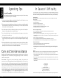
1
†
†
pxm250/450/900
Professional Stereo Power Amplifier
Made In America
8100.0157A
†Available in North America only
A Division Of Phoenix Gold International, Inc.
9300 North Decatur ● Portland OR 97203 ● Tel: 503.288.2008
●
Fax: 503.978.3302 ● Email: [email protected]
Introduction
Safety Information
CAUTION
RISK OF ELECTRIC SHOCK
DO NOT OPEN
CAUTION: TO REDUCE THE RISK OF ELECTRIC SHOCK
DO NOT REMOVE COVER (OR BACK)
NO USER-SERVICEABLE PARTS INSIDE
REFER SERVICING TO QUALIFIED SERVICE PERSONNEL
The lightning flash with arrowhead
symbol within an equilateral triangle
is intended to alert the user to the
presence of uninsulated"dangerous
voltage" within the product's
enclosure, that may be of sufficient
magnitude to constitute a risk of
electric shock to persons.
The exclamation point within an
equilateral triangle is intended to alert
the user of the presence of important
operating and maintenance (servicing)
instructions in the literature
accompanying the appliance.
Table Of Contents
Introduction ............................................................2
Unpacking and Paperwork.....................................2
Features and Specifications
PXm250 ..........................................................3-4
PXm450 ..........................................................5-6
PXm900 ..........................................................7-8
Controls and Functions.....................................9-10
Installation and Operation
Location and General Precautions....................11
Mechanical Considerations ..............................11
Rear Support.....................................................11
Thermal Considerations....................................11
AC Power Considerations................................11
Magnetic Leakage Considerations ...................11
Input Wiring......................................................11
Standard Version.........................................11
BR Version..................................................12
High Pass Filter ..........................................12
Installation (continued)
High Pass Filter Cut Off .............................13
Clip Limiter ................................................13
Input Sensitivity..........................................13
Output Wiring.............................................13
Multi-way binding Posts.............................13
Polarity........................................................13
Bridged Mono.............................................14
Parallel Mono..............................................14
70V Distribution Systems...........................14
70V Direct Drive ........................................14
Operating Tips......................................................15
Care and Service Assistance ................................15
In Case of Difficulty.............................................16
Warranty Information...........................................17
Cables and Accessories ........................................18
Congratulations on your purchase of a new Carver Professional Power Amplifier. The PXm250,
PXm450 and PXm900 are designed for any pro audio application. The PXm amplifiers are
designed and produced by Carver Professional, a division of Phoenix Gold International, Inc.
They combine the experience in pro audio and sonic heritage of Carver Professional with the performance, manufacturing quality and attention to detail that has defined Phoenix Gold
International. Thank you for placing your confidence in Carver Professional and Phoenix Gold. We know
your amplifier will provide many years of dependable service and reliable sound reproduction.
Please read this entire manual, especially the Safety Warnings, before operating your amplifier.
Unpacking and
Paperwork
Carefully unpack the amplifier and keep the original carton and packing materials for future moving, shipment
or long-term storage. After opening the box, please check for visible signs of damage that were not apparent
from the outside of the box. If you encounter what appears to be concealed damage, please consult your
Carver Professional Dealer before installing unit.
Important Paperwork
Make sure to save your sales receipt. Your receipt is extremely important to establish the duration of your
Limited Warranty and for insurance purposes. Next, make a note of the serial number, which is located on
the back of the amplifier. Record it in the space provided below for convenient reference.
Model: ___PXm250 ___PXm250BR ___PXm250SP
___PXm450 ___PXm450BR ___PXm450SP
___PXm900 ___PXm900BR ___PXm900SP
Serial Number: _____________________________
Purchased at: _______________________________
Date: _____________________________________
Finally, take a moment to fill out the Warranty Registration Card packed with the amplifier and return it to
Carver Professional. This will allow us to keep you informed about new products, as they become available.
2
PXm250
• 250W bridged mono into 8 ohms
175W per channel into 2 ohms
125W per channel into 4 ohms
75W per channel into 8 ohms
•
Three connector versions available:
Standard - XLR and 1/4" TRS inputs with
Multi-way Binding Posts
BR Version - Barrier Strip inputs with
Multi-way Binding Posts
SP Version - XLR and 1/4" TRS inputs with
Neutrik™ Speakons™
• Independent level controls for CH1 & CH2
• Independent CH1 and CH2 switchable High Pass
Filters, selectable at 30Hz or 80Hz
• Independent CH1 and CH2 selectable Clip Limiters
• Independent CH1 and CH2 selectable Input
Sensitivity @ 0.775Vrms or 1.5Vrms
• Externally configurable for Parallel Mono mode,
to operate both channels with a mono signal
• Externally configurable for Bridged Mono mode,
to combine the power of both channels into a
higher powered mono channel
• Protection circuitry includes Thermal and
Short Circuit
• Power Ready, Signal Present, Clip, Protect and
Thermal LED indicators for each channel
• Variable speed fan cooling
• RAMPoptional computer monitoring port
Power Output, both channels driven:
(1kHz, 1%THD), 175W per
channel into 2 ohms, 125W
per channel into 4 ohms,
75W per channel into 8
ohms
Continuous Average Output Power, both
channels driven:
(20Hz to 20kHz, with no more
than 1% THD), 120W per
channel into 4 ohms, 70W per
channel into 8 ohms
Bridged-mono operation:
250W into 8 ohms, 1kHz,
<1% THD
240W into 8 ohms 20Hz to
20kHz, <1% THD
Parallel-mono operation:
70W per channel into 8
ohms, from 20Hz to 20kHz,
<1% THD
120W per channel into 4
ohms, from 20Hz to 20kHz,
<1% THD
Dynamic Headroom: 2.0dB
Frequency Response:20Hz to 20kHz (+/- 0.5 dB)
Channel Separation: >55dB @ 1kHz
Damping Factor:
> 180
Input Impedance:
20K ohms, balanced
Sensitivity:
0.775V / 1.5V rms for rated
power into 4 ohms
Gain:
29dB, 23dB dependent on
sensitivity
Input Overload:
+20dBu
THD:
<0.1% @ 60W
IM Distortion:
<0.15%
Signal-to-Noise Ratio:
>104dB, A-weighted,
ref. to rated power into 8
ohms
Slew Rate:
29V/µ Sec.
CMRR:
55dB @ 1kHz Typical
Current Consumption:
41w @ idle, 144w with
musical program, 424w @ full
power into 8 ohms,
(continuous), 643w @ full
power into 4 ohms
(continuous)
Power Requirements:
120VAC/60Hz (USA and
Canada). Other voltages as
required for export
Display:
5 LED indicators per channel;
1 red CLIP
1 yellow SIGNAL
1 green POWER ON
1 red PROTECT
1 red THERMAL
Size (H x W x D):
3.5" (2U) x 19" x 15.38"
89mm x 483mm x 391mm
Net Weight:
24.4 lbs., (11.1 kg)
Shipping Weight:
28.0 lbs., (12.7kg)
Due to ongoing research and development,
all specifications and features are subject to change
without notice.
Barrier strip input version available. Order
PXm250BR.
Neutrik™ Speakon™ version available. Order
PXm250SP.
Handle Kit available. Order PX2HK.
The PXm250 series is available in 100V, 120V and
230V 50/60Hz.
3
4
PXm450
• 450W bridged mono into 8 ohms
275W per channel into 2 ohms
225W per channel into 4 ohms
150W per channel into 8 ohms
•
Three connector versions available:
Standard - XLR and 1/4" TRS inputs with
Multi-way Binding Posts
BR Version - Barrier Strip inputs with
Multi-way Binding Posts
SP Version - XLR and 1/4" TRS inputs with
Neutrik™ Speakons™
• Independent level controls for CH1 & CH2
• Independent CH1and CH2 switchable High Pass
Filters, selectable at 30Hz or 80Hz
• Independent CH1and CH2 selectable Clip Limiters
• Independent CH1 and CH2 selectable input
sensitivity @ 0.775Vrms or 1.5Vrms
• Externally configurable for Parallel Mono mode,
to operate both channels with a mono signal
• Externally configurable for Bridged Mono mode,
to combine the power of both channels into a
higher powered mono channel
• Protection circuitry includes Thermal and
Short Circuit
• Power Ready, Signal Present, Clip, Protect and
Thermal LED indicators for each channel
• Variable speed fan cooling
• RAMP optional computer monitoring port
Power Output:, both channels driven:
(1kHz, 1%THD), 275W per
channel into 2 ohms, 225W
per channel into 4 ohms,
150W per channel into 8
ohms
Continuous Average Output Power, both
channels driven:
(20Hz to 20kHz, with no
more than 1% THD)
215W per channel into 4
ohms 140W per channel into
8 ohms
Bridged-mono operation:
450W into 8 ohms, 1kHz,
<1% THD
430W into 8 ohms 20Hz to
20kHz, <1% THD
Parallel-mono operation:
140W per channel into 8
ohms, from 20Hz to 20kHz,
<1% THD
215W per channel into 4
ohms, from 20Hz to 20kHz,
<1% THD
Dynamic Headroom: 2.0dB
Frequency Response:20 Hz to 20kHz (+/- 0.5 dB)
Channel Separation: >55dB @ 1kHz
Damping Factor:
> 200
Input Impedance:
20K ohms, Balanced
Sensitivity:
0.775V / 1.5V rms for rated
power into 4 ohms
Gain:
31.8dB, 25.8dB dependent
on sensitivity
Input Overload:
+20dBu
THD:
<0.1% @ 100W
IM Distortion:
<0.15%
Signal-to-Noise Ratio:
>108dB, A-weighted,
ref. to rated power into 8
ohms
Slew Rate:
29V/µ Sec.
CMRR:
55dB @ 1kHz Typical
Current Consumption:
54w @ idle, 216w with
musical program, 640w @ full
power into 8 ohms,
(continuous), 976w @ full
power into 4 ohms
(continuous)
Power Requirements:
120VAC/60Hz (USA and
Canada) Other voltages as
required for export
Display:
5 LED indicators per channel;
1 red CLIP
1 yellow SIGNAL
1 green POWER ON
1 red PROTECT
1 red THERMAL
Size (H x W x D):
3.5" (2U) x 19" x 15.38"
89mm x 483mm x 391mm
Net Weight:
26.3 lbs. (12.0 kg)
Shipping Weight:
30.4 lbs. (13.8 kg)
Due to ongoing research and development, all
specifications and features are subject to change
without notice.
Barrier Strip input version available. Order
PXm450BR.
Neutrik™ Speakon™ version available. Order
PXm450SP.
Handle Kit available. Order PX2HK.
The PXm450 series is available in 100V, 120V
and 230V 50/60Hz.
5
6
PXm900
• 900W bridged mono into 8 ohms
550W per channel into 2 ohms
450W per channel into 4 ohms
300W per channel into 8 ohms
connector versions available:
• Three
Standard XLR and 1/4" TRS inputs with
Multi-way Binding Posts
BR Version - Barrier Strip inputs with
Multi-way Binding Posts
SP Version - XLR and 1/4" TRS inputs with
Neutrik™ Speakons™
• Independent Level controls for CH1 & CH2
• Independent CH1 and CH2 switchable High Pass
Filters, selectable at 30Hz or 80Hz
• Independent CH1 and CH2 selectable Clip Limiters
7
• Independent CH1 and CH2 selectable input
sensitivity @ 0.775Vrms or 1.5Vrms
• Externally configurable for Parallel Mono mode,
to operate both channels with a mono signal
• Externally configurable for Bridged Mono mode,
to combine the power of both channels into a
higher powered mono channel
• Protection circuitry includes Thermal, Short
Circuit and DC Fault
• Power Ready, Signal Present, Clip, Protect and
Thermal LED indicators for each channel
• Variable speed fan cooling
• RAMP optional computer monitoring port
Power Output, both channels driven:
550W per channel into 2
ohms 450W per channel into
4 ohms 300W per channel
into 8 ohms
Continuous Average Output Power, both
channels driven: (20Hz to
20kHz, with no more than
1% THD) 440W per channel
into 4 ohms 280W per
channel into 8 ohms
Bridged-mono operation:
900W into 8 ohms, 1kHz,
<1% THD
880W into 8 ohms 20-20kHz,
<1% THD
Parallel-mono operation:
280W per channel into 8
ohms, from 20Hz to 20kHz,
<1% THD
440W per channel into 4
ohms, from 20Hz to 20kHz,
<1% THD
Dynamic Headroom: 2.0dB
Frequency Response:20 Hz to 20kHz (+/- 0.5 dB)
Channel Separation: >55dB @ 1kHz
Damping Factor:
> 200
Input Impedance:
20K ohms, Balanced
Sensitivity:
0.775V / 1.5V rms for rated
power into 4 ohms
Gain:
34.8dB, 28.7dB dependent
on sensitivity
Input Overload:
+20dBu
THD:
<0.1% @ 200W
IM Distortion:
<0.15%
Signal-to-Noise Ratio:
>113dB, A-weighted,
ref. to rated power into 8
ohms
Slew Rate:
29V/µ Sec.
CMRR:
55dB @ 1kHz Typical
Current Consumption:
94w @ idle, 384w with
musical program, 1135w @
full power into 8 ohms,
(continuous), 1792w @ full
power into 4 ohms
(continuous)
Power Requirements:
120VAC/60Hz
(USA and Canada)
Other voltages as required
for export
Display:
5 LED indicators per channel;
1 red CLIP
1 yellow SIGNAL
1 green POWER ON
1 red PROTECT
1 red THERMAL
Size (H x W x D):
5.75” (3U) x 19” x 15.38”
133mm x 483mm x 391mm
Net Weight:
38.5 lbs. (17.5kg)
Shipping Weight:
44.0 lbs. (20.0kg)
Due to ongoing research and development, all
specifications and features are subject to change
without notice.
Barrier Strip input version available. Order
PXm900BR.
Neutrik™ Speakon™ version available. Order
PXm900SP.
Handle Kit available. Order PX4HK.
The PXm900 series is available in 100V, 120V
and 230V 50/60Hz.
8
Installation
Location and General Precautions
Observe the following precautions when choosing a location for your amplifier.
A. Do not expose the unit to rain or moisture. If a fluid or foreign object should enter the unit, disconnect the power
plug and contact an authorized dealer or service center. Do not pull the plug by pulling on the cord; grasp the plug
firmly.
B. Protect from heat and allow adequate ventilation. Place away from direct sources of heat, such as heating vents and
radiators. All components produce some heat during operation, so make sure that the ventilation slots are not covered
and that air is allowed to circulate freely behind and above the unit. Excessive heat is the single greatest source of premature
component failure.
Mechanical Considerations
The PXm250 and PXm450 require two rack space units (3.5") and the PXm900 three rack space units (5.25"). All three have a
depth of 15.38" inside the rack, including the rear supports. Secure the unit mechanically using four screws with washers to prevent
marring the front panel. Neoprene rubber washers are a good choice because they grip the screw head and prevent them from
backing out when vibrated or transported.
Rear Support for Road Applications
If the PXm amplifiers are rack mounted, and the rack is transported, mechanical support for the rear of the amplifiers is required.
This could take the form of a shelf across the rear of the rack or brackets that engage the rear of the unit.
Thermal Considerations
When PXm amplifiers are used freestanding, no thermal considerations are necessary other than keeping the ventilation slots open.
If the amplifiers are rack-mounted, ensure that adequate ventilation exists in front of, behind and to the sides of the amplifier.
When several amplifiers are mounted together in a rack, you may need to provide air inlets from the outside of the rack. The PXm
amplifiers are fan cooled. The fan is internally mounted so that it draws air from the back and left side, and exhausts it out the
front. The PXm amplifiers may be stacked directly on top of each other without spacer panels. If the amplifiers are used with
other amplifiers, ensure that the heat output from the other amplifiers doesn't interfere with the ventilation of the PXm amplifier
(or vice versa).
AC Power Considerations
Ensure that the PXm amplifier is plugged into an outlet capable of supplying the correct voltage specified for your model and
enough current to allow full-power operation of all amplifiers plugged into it. The current demand of a power amplifier varies
depending on several factors, including the impedance of the load, the output level of the amplifier, and the crest factor and duty
cycle of the program material. Under typical conditions reproducing rock music, with both channels driven into 4 ohms to the
point where musical peaks are just at the clipping point, the amplifiers require the following average currents:
PXm250:
1.8A for 120V versions, .94Afor 230V versions
PXm450:
2.5A for 120V versions, 1.3A for 230V versions
PXm900:
5A for 120V versions, 2.6A for 230V versions
For balanced operation:
1/4 inch phone plug: Use a 3-conductor TRS (tip-ring-sleeve) 1/4" phone plug. The tip of the plug carries the "+"
(high, non-inverting) side of the signal, the ring carries the "-" (low, inverting) side of the signal and the sleeve is
ground (see Figure A).
XLR: Use a male XLR connector. Pin 2 carries the "+" (non-inverting) side of the signal, Pin 3 carries the "-" (low,
inverting) side of the signal, and Pin 1 is ground (see Figure B).
For unbalanced operation:
1/4" phone plug: Use a 2-conductor (tip-sleeve) 1/4" phone plug. The tip of the plug carries the signal and the
sleeve is the ground. The sleeve (see Figure C) automatically grounds the ring connection in the jack.
XLR: Pin 2 carries the signal, and Pin 1 is ground. Short Pin 3 to Pin 1 in order to reference the input differential amplifier for
the correct gain (see Figure D).
BR Version
For balanced operation:
Use shielded twisted pair balanced line type cable with crimp-on or solder type 8mm spade terminals. For either channel
connect the "+" (high, non-inverting) side of the signal to the terminal labeled "+" on the Barrier Strip. Connect the "-" (low,
inverting) side of the signal to the terminal labeled "-" on the Barrier Strip. Connect the shield to the "ground" terminal (see
Figure E).
NOTE: Confirm which wires are "+" and "-" from the source unit. Refer to the 1/4" plug and XLR instructions for proper
configuration if these plugs are used at the source unit.
For unbalanced operation:
Use shielded single conductor coax type cable or twisted pair balanced line type cable with crimp-on or solder type spade
terminals. Connect the hot side of the signal to the terminal labeled "+" on the Barrier Strip. Connect the shield to "ground" and
connect a jumper wire between "ground" and the (-) terminal (see Figure F).
Figure A
Figure B
TIP
+
+ –
Standard Version
The 1/4" TRS input connectors will accept either unbalanced 1/4" phone plugs or balanced 1/4" TRS phone plugs. The female
XLR will accept a male XLR connector. The input signal can be used with either unbalanced shielded single conductor or
balanced shielded 2 conductor cables. Use shielded coaxial cable to conduct the signal from the source (i.e. mixer, equalizer,
CD player) to the amplifier.
11
GND
(Shield)
+ –
From
Channel 2
Figure D
GND
(Shield)
From
Channel 1
Figure E
Magnetic Leakage Considerations
The PXm amplifiers may be mounted without concern for magnetic flux leakage, within the confines of common sense. For
example, it's not a good idea to mount any power amplifier near a microphone input transformer or magnetic storage media.
Input Wiring
(See page 18 for recommended Carver Professional Accessories)
Figure C
From
Channel 2
GND
(Shield)
+
GND
(Shield)
From
Channel 1
SLEEVE
(Shield)
From
Channel 2
From
Channel 1
Figure F
+
+
TIP
+
SLEEVE
(Shield)
–
+
GND
(Shield)
GND
(Shield)
From
Channel 2
From
Channel 1
From
Channel 2
From
Channel 1
High Pass Filter
This filter will remove unwanted low frequency components from the input signal when engaged. It is engaged or disabled from
the Dip Switch located on the rear panel of the amplifier. The High Pass Filter is switched independently for each channel at
position #1 for CH2 and position #5 for CH1. The High Pass Filter is set at the factory to its disabled position.
12
High Pass Filter Cut Off Frequency
The High Pass Filter Cut Off frequency is independently selectable for each channel at a frequency of either 30Hz or
80Hz.
In the 30Hz position this filter performs much like a subsonic filter, eliminating power-robbing low frequencies below
the audible or useable range. In the 80Hz position the High Pass Filter protects sensitive high frequency drivers from
low frequency transients that could damage voice coils or diaphragms. The 80Hz position also is effective when used
in conjunction with a 70V distributed system by preventing low frequencies from saturating the transformers. The DIP
Switch positions for the High Pass Filter Cut Off are position #2 for CH2 and position #6 for CH1. The High Pass
Filter Cut Off is set at the factory to the 30Hz position, however the High Pass Filter is disabled when the unit is shipped
from the factory.
NOTE: When using the PXm amplifiers, or any high powered amplifier, in multi-way systems
as a high frequency amplifier, it is recommended that a capacitor be used in series with the high
frequency drivers. This will ensure that the delicate high frequency voice coils are protected in
case of a catastrophic amplifier failure.
Clip Limiter
The Clip Limiter when engaged will reduce the negative effects of clipping when the source signal
overdrives the amplifier. It should be noted that if the input signal contains clipped signals when
it arrives at the amplifiers input, the Clip Limiter will not eliminate this unwanted distortion. The
Clip Limiter is engaged independently for each channel on the DIP Switch located on the rear
panel of the amplifier at switch position #3 for CH2 and switch position #7 for CH1. The Clip
Limiter is set at the factory to its disabled position.
Input Sensitivity
The input sensitivity can be changed to 1.5Vrms. The input sensitivity is set independently for
each channel on the DIP Switch located on the rear panel of the amplifier. Input sensitivity is
switched at position #4 for CH2 and at position #8 for CH1. The input sensitivity is set at the
factory to .775Vrms for rated output.
Bridged Mono
"Bridged Mono" mode is used to tie the two amplifier channels together thereby doubling the power of the amp into a mono
load. To configure the amplifier for "Bridged Mono" operation, change the output configuration switch located on the back
panel of the amplifier. When in the "Bridged Mono" setting connect the input signal to CH2 input (CH1 input is disabled in
"Bridged" mode). Connect the speaker(s) to the two red or (+) speaker terminals. The CH2 (+) terminal is the high (+, or
non-inverting) side, and the CH1 (+) terminal is the low (-, or inverting) side. When connected in this way, each channel
"sees" one-half the impedance of the speaker(s) that are connected between them. If an 8 ohm speaker is used, each channel
will see a 4 ohm load. Therefore it is not recommended that any load lower than 8 ohms be connected between the speaker
terminals in this mode of operation. Use Parallel Mono operation for lower impedance loads. (CH1 input and CH1 level
control are disabled).
1) CAUTION: In "Bridged Mono" operation, the output connections are actually a balanced output configuration. This
means that both output terminals have voltage present (neither one may be grounded). If through negligence you should become the
ground, the voltages may be dangerous.
2) Never change the output configuration switch from one mode to another with the amplifier powered "ON". Always make sure that the
proper connections have been made for the operating mode selected before turning power "ON".
Parallel Mono
"Parallel Mono" mode allows both channels to be driven simultaneously with a single (mono) input. To configure the amplifier for
Parallel Mono operation, change the output configuration switch located on the back panel of the amplifier. Connect the input source to
CH2. Connect speaker(s) to CH1 or CH2 or both. (CH1 input and CH1 level control are disabled).
Note: To daisy chain the input signal to additional amps, use the unused input connector on CH2.
Dip Switch
Output Wiring
(See page 18 for recommended Carver Professional Accessories.)
Use heavy gauge cable for speaker connections. As the distance between the amplifier and the speakers increases, the cable diameter
should be larger to minimize power loss across the cable, and to improve the damping of the speaker. Cable thickness specifications (or
gauges) get smaller as the cable gets thicker, thus a 14 gauge cable is thicker than 16 gauge cable. Use the following as a guide: up to 25
feet use 16 gauge cable, up to 40 feet use 14 gauge cable, up to 60 feet use 12 gauge cable, up to 100 feet use 10 gauge cable, up to 150
feet use 8 gauge cable and up to 250 feet use 6 gauge cable. This will ensure that the resistance of the speaker cable is less than 5% of 4
ohms, resulting in a transmission loss of less than 0.5dB. Class 1 (NEC) cable must be used.
70V Distribution Systems
The PXm amplifiers can be used to drive 70V distributed systems using Carver Professional output distribution transformers (available
separately from your Carver Professional dealer. Order XO125 for the PXm250. Order XO200a for the PXm450 and for the PXm900
order the XO450a. Connect one transformer to the output of each amplifier channel to deliver 125 watts for the PXm250, 225 watts for
the PXm450 and 450 watts for the PXm900 to the 70-volt system. As with all 70-volt systems, step down transformers are required at
each loudspeaker. The XO125 has taps for 25Vand 70Vsystems, the XO200Ahas taps for 25V and 70Vsystems and the XO450A has
taps for 70Vand 100Vsystems. When using the amplifier in a 70Vdistributed system with transformers, it is advisable to set the “High
Pass” filter to “On” and the “Cut-off Frequency” to 80 Hz. This prevents frequencies below 50 Hz from possibly saturating the
transformers, and appearing to the amplifier as a short circuit.
70V Direct Drive
The PXm900 has sufficient output voltage to drive a 70V distributed system without the use of a step-up transformer, in the "Bridged
Mono" mode. The PXm900 can deliver 900 watts to the 70-volt system in the "Bridged Mono" mode.
Multi-way Binding Posts: This output connector can accept a spade lug, bare wire, or banana connections (except CE approved
versions). Be sure that all the fine strands of the cable are twisted together and contained within the connector. If even one strand is loose
and can touch the adjacent terminal, a short circuit may result.
Polarity
Loudspeakers must be connected with consistent polarity for correct phasing between them. Incorrect phasing will do no physical harm,
but frequency response will be affected. The key is to make sure that all speakers connected to the speaker terminals are hooked up the
same way. Connect the black post (-) at the speaker output of the amplifier to (-) on the back of the speaker, and the red post (+) on the
speaker output of the amplifier to (+) on the back of the speaker.
13
14
Operating Tips
Using the PXm Amplifiers
Once the amplifier has been installed and wired into the system, you are ready to use it. Here are some tips
to help you get the most from your new PXm amplifier.
• Verify that the switches (Output Configuration, Input Sensitivity, High Pass Filter and Clip Limiter) have been set
to the mode or selection that you had intended for your application.
• When you power up the system for the first time (out of the carton), it's a good idea to start with all of the amplifier
level controls turned down (counter-clockwise), then advance them slowly, one at a time, so that you can confirm
that each amplifier channel is operating normally.
• Be sure that the input level controls are set sufficiently high to allow the preceding device to drive the amplifier to
full output. For most installations, this is wide open (fully clockwise).
• Once you have established settings, it is a good idea to mark them down, either on paper, or on pieces of tape or
sticky-dots attached to the amplifier's panel.
• In bi-amplified (multi-amp) systems, it is a good idea to start with the low-frequency amplifiers turned down, and
to check each frequency range from highest to lowest to ensure that each loudspeaker component is operating
correctly.
• When using the PXm amplifiers, or any high powered amplifier, in multi-way systems as a high frequency amplifier,
it is recommended that a capacitor be used in series with the high frequency drivers. This will ensure that the delicate
high frequency voice coils are protected in case of a catastrophic amplifier failure.
Care and Service Assistance
Care: Wipe off the PXm Amplifier's front panel and chassis from time to time, with a soft, dry cloth. If you have
something stubborn to remove, use a mild dish soap or detergent applied sparingly to a soft cloth. Don't use alcohol,
ammonia or other strong solvents.
Service Assistance: We suggest that you read the Limited Warranty completely to fully understand your
warranty/service coverage. Please promptly complete and return the Warranty registration card. Also, be sure to save
the sales receipt in a safe place. It will be necessary for warranty service. If your Carver Professional product should
require service, you may contact the Carver Professional Technical Service Department by calling (503) 978-3363 or by
writing to us at the Factory address found on page 16. We will then direct you to the nearest in our national network of
Authorized Warranty Service Centers, or give you detailed instructions on how to return the product to us for prompt
action. If you should have questions or comments, please write to the Factory address shown on page 19, or contact us
via email at [email protected] or at our web site: http://www.carverpro.com. Please include the model and
serial number of your Carver Professional product, your complete address and daytime phone number.
15
In Case of Difficulty
If you are having trouble, or suspect a problem with your PXm amplifier, try some simple troubleshooting before contacting
an Authorized Carver Professional Dealer, Authorized Carver Professional Service Center or Carver Professional Technical
Service. Below are listed some general problems and items that should be checked in an attempt to resolve the difficulty.
No Sound, No Power
This is usually an indication of a power supply problem, in either the power line itself or the amplifier's power supply.
Check the following:
1. PXm amplifier power is switched off.
2. Line cord is disconnected.
3. Poor fit between the plug and AC receptacle.
4. Power off at AC receptacle (check with tester or lamp).
5. The amplifier is plugged into a switched outlet. Verify that the outlet is live.
6. PXm amplifier fuse has blown. Check and replace fuse.
Power On, Low Output or No Output
Low or no output problems are usually signal-source, bad cable or partial output short circuit related.
1. The input level controls are set too low.
2. Move the input connection to another amplifier that you know is working to verify that it is not a source problem.
3. Check speaker connections. Be sure that there are no small strands of wire touching similar strands coming from the other
wire in the cable.
4. Make sure the speakers are functioning correctly.
5. If you are using bridged-mono mode, ensure that the Output Configuration Switch is set correctly.
6. Use a voltmeter to determine if the power line voltage is dropping excessively when the amplifier is driven hard.
Playback Is Mixed with Hum
1. Check or replace the connecting cables, between source and amplifier's input.
2. Make sure that each screw terminal connection is tight.
3. Signal cables may have been routed too closely to the AC cables, power transformers, motors or EMI inducing device.
4. Try connecting another source to the power amplifier inputs. If the hum stops, the problem lies with the original source
component.
Distortion
Distortion is usually caused by excessive loss in the input controls (the mixer/equalizer/crossover cannot produce enough
output), overdriving resulting in output clipping, or current limiting caused by excessively low load impedance.
1. Check the setting of the input level controls. If set too low, the preceding piece of equipment may not have sufficient output to overcome the loss.
2. Check the speaker connections and verify that all screw connections are tight and that there are no stray strands of wire to
cause short circuits.
3. Verify that the total load impedance presented to the amplifier is within the limits described in this manual for the mode of
operation selected.
Carver Professional
Service Department
P.O. Box 83189
Portland, Oregon 97283
Phone 503.978.3363 • Fax 503.978.3302
E-mail: [email protected]
Web Page: http://www.carverpro.com
Carver Professional reserves the right to improve its products at any time. Therefore, specifications are subject to change without notice.
16
Warranty Information
Professional Power Amplifiers: 5 years
NOTE: The following warranty is exclusive to the United States and its possessions and territories. Please see
your Carver Professional dealer or distributor for the correct warranty information in your area or locale.
WHAT IS COVERED:
THIS WARRANTYCOVERS DEFECTS IN MATERIALAND WORKMANSHIPONLY. This limited Warranty DOES NOT
extend to: 1) damage caused by shipment, 2) damage caused by accident, misuse, abuse, failure to perform owner maintenance,
or operation contrary to the instructions in the Carver Professional owner's manual, 3) units on which the serial number has
been defaced, modified or removed and 4) damage resulting from modification or attempted repair by any other person than
authorized by Carver Professional.
Cables and Accessories
For the optimum connection of your PXm amplifier, here is a sample of the many accessory products available from Carver
Professional. For more information on these accessories, or to receive a full-line catalog of Carver Professional Accessories,
see your Authorized Carver Professional Dealer / Contractor, or contact Carver Professional at 503-978-3344.
Email: [email protected] Web Site: http://www.carverpro.com
CONNECTORS
• 1/4" Connectors (Balanced)
RM4MS5
• 1/4" Connectors (Unbalanced)
RS4MM5
• XLR Connectors
GSXM7
GSXF7
RSXM7
RSXF7
Gunmetal Grey Plated Male XLR Connector (accepts 7.0mm Cable)
Gunmetal Grey Plated Female XLR Connector (accepts 7.0mm Cable)
Nickel Plated Male XLR Connector (accepts 7mm Cable)
Nickel Plated Female XLR Connector (accepts 7mm Cable)
• Spade Terminals
CP PRO8
CP PRO80
CP PRO404
CP PRO81
Pro Series 7-9 Gauge Multi-Stud Spade
Pro Series 7-9 Gauge Slotted spade
Pro Series 12-16 Gauge Spade
Pro Series 7-9 Gauge Slotted Right Angle Spade
• Banana Plugs
CPA405
CPA408
CP ZPB1
CP Dual
CP PRO Dual
4.0mm tighter fitting Multi-Purpose Banana for 16-18 Gauge
Crimp-on 4.0mm Banana Plug for 12-16 Gauge
Crimp-on 4.0mm Banana Plug for 8-12 Gauge ZeroPoint Reference Cable
Dual 4.0mm Banana Plug for 12-18 Gauge
Pro Dual 4.0mm Banana Plug for 9-14 Gauge
YOU MUSTRETAIN AND PROVIDE YOUR SALES RECEIPTTO OBTAIN COVERAGE UNDER THIS LIMITED
WARRANTY.
• Neutrik™ Speakons™
CP NL4FC
CP NL8FC
4 Conductor Female Cable Mount Connector
8 Conductor Female Cable Mount Connector
The warranty period begins from the date of the first consumer purchase from an Authorized Carver Professional Dealer. Any
implied warranties for merchantability and fitness for a particular purpose required by any state law are limited in duration to
the warranty period of your product. The warranty set forth above is exclusive and no other, written or oral, is expressed or
implied. Carver Professional specifically disclaims the implied warranties and merchantability and fitness for a particular
purpose.
SIGNAL CABLE WITH CONNECTORS
• ZEROpoint PRO QLX Quadralink Twisted Pair Balanced Grade Cable w/ 1/4" TRS plugs
• ZEROpoint PRO QLX Quadralink Twisted Pair Balanced Grade Cable w/ XLR to XLR
• True Balanced Pro OFC Cables w/Dual 24kt Gold Plated GS Series 1/4" Plugs
Carver Professional will pay all labor and material expenses for items covered under this Limited Warranty. See the next
section concerning shipping charges.
WHAT YOU MUST DO TO OBTAIN WARRANTY SERVICE:
In the event your Carver Professional product requires service, contact your Carver Professional Authorized Dealer /
Contractor or contact Carver Professional (ATTN: Customer Service Dept.) P.O. Box 83189, Portland, OR 97283, or call
Customer Service Department directly at (503) 978-3363. You will be directed to an Authorized Carver Professional Service
Station or receive instructions to ship the unit to the factory. Please save the original carton and packing materials in case
shipping is required. Please do not ship parcel post. Include a complete description of the problem, the associated components
and connections, and a copy of the purchase receipt. Carver Professional does not pay initial shipping costs. Return shipping
costs will be pre-paid if repairs were covered by the scope of this warranty.
EXCLUSION OF CERTAIN DAMAGES:
In no event shall Carver Professional be liable for property damage, or any other incidental or consequential damages, which
may result from failure of this product. If your Carver Professional product proves defective in material or workmanship, the
liability of Carver Professional shall be limited to the repair or replacement, at the option of Carver Professional, of any
defective part.
STATE LAWS MAY DIFFER:
Some states do not allow limitations on how long an implied warranty lasts and/or do not allow the exclusion or limitation of
incidental or consequential damages, so the above limitations may not apply to you. This warranty gives you specific legal
rights, and you may have other rights, which vary, from state to state.
OTHER IMPORTANT PROVISIONS:
Carver Professional reserves the right to make changes in design and improvements to its products without the responsibility
of installing such changes or improvements on products previously sold by Carver Professional. We suggest that you attach
your purchase receipt to this Warranty and keep both documents in a safe place. Thank you for your choice of a Carver
Professional Amplifier.
GS4MM5
TRS Plug - Solder Cup type w/24kt Gold Plated Plug
(accepts 5.0mm Cable)
TRS Plug Nickel Plated (accepts 5.0mm cable)
Mono Phone Plug - Solder Cup type w/24kt Gold Plated Plug
(accepts 5.0mmCable)
Mono Phone Plug - Nickel Plated (accepts 5.mm Cable)
WHAT WE WILL PAY FOR:
17
GS4MS5
SIGNALCABLE BULK
• ZEROpoint Musical Reference Interconnect Cable-Sapphire Blue
• ZEROpoint Pro Twisted Pair Interconnect Cable
• ZEROpoint PRO QLX Quadralink Interconnect Cable
• ZEROpoint TRX PRO - Interconnect Cable
SPEAKER CABLE WITH CONNECTORS
• Super OFC 2 Conductor Speaker Cable - 1/4" To Dual Banana
• Mondo Series 2 Conductor Speaker Cable 10, 12, 14, 16 AWG - 1/4" Plugs
• Mondo Multi Series Ultra Flexible Round 2 Conductor Cable - Neutrik™ Speakons™
• Mondo Multi Series Ultra Flexible Speaker snakes w/3' Fan Ends - Various Connector Combinations Available
SPEAKER WIRE BULK
• ZeroPOINT Musical Reference Speaker Wire - 2 and 4 Conductor
• Mondo Series Ultra Flexible Round 2 Conductor Speaker Wire
• Mondo Multi Series Ultra Flexible Round 13 AWG Multi Conductor Speaker Wire
70V TRANSFORMERS
• XO125 for use with PXm250 in 70V distributed systems
• XO200a for use with PXm450 in 70V distributed systems
• XO450a for use with PXm900 in 70V distributed systems
18
†
†
pxm250/450/900
Professional Stereo Power Amplifier
Made In America
8100.0157A
†Available in North America only
A Division Of Phoenix Gold International, Inc.
9300 North Decatur ● Portland OR 97203 ● Tel: 503.288.2008
●
Fax: 503.978.3302 ● Email: [email protected]