1
User Guide
Audio Products:
Mixers and Processors
DMP 44 LC
Four-Line Input and Four-Line Output
Digital Matrix Processor
68-1938-01
Rev. B
05 12
Safety Instructions • English
Warning
This symbol is intended to alert the user of important operating and maintenance (servicing) instructions in the literature provided with the equipment.
Power sources • This equipment should be operated only from the power source indicated on the product. This
equipment is intended to be used with a main power system with a grounded (neutral) conductor. The third
(grounding) pin is a safety feature, do not attempt to bypass or disable it.
This symbol is intended to alert the user of the presence of uninsulated
dangerous voltage within the product’s enclosure that may present a risk of
electric shock.
Power disconnection • To remove power from the equipment safely, remove all power cords from the rear of
the equipment, or the desktop power module (if detachable), or from the power source receptacle (wall plug).
Caution
Read Instructions • Read and understand all safety and operating instructions before using the equipment.
Retain Instructions • The safety instructions should be kept for future reference.
Follow Warnings • Follow all warnings and instructions marked on the equipment or in the user information.
Avoid Attachments • Do not use tools or attachments that are not recommended by the equipment
manufacturer because they may be hazardous.
Consignes de Sécurité • Français
Ce symbole sert à avertir l’utilisateur que la documentation fournie avec le
matériel contient des instructions importantes concernant l’exploitation et la
maintenance (réparation).
Ce symbole sert à avertir l’utilisateur de la présence dans le boîtier
de l’appareil de tensions dangereuses non isolées posant des risques
d’électrocution.
Attention
Lire les instructions• Prendre connaissance de toutes les consignes de sécurité et d’exploitation avant
d’utiliser le matériel.
Conserver les instructions• Ranger les consignes de sécurité afin de pouvoir les consulter à l’avenir.
Respecter les avertissements • Observer tous les avertissements et consignes marqués sur le matériel ou
présentés dans la documentation utilisateur.
Eviter les pièces de fixation • Ne pas utiliser de pièces de fixation ni d’outils non recommandés par le
fabricant du matériel car cela risquerait de poser certains dangers.
Sicherheitsanleitungen • Deutsch
Power cord protection • Power cords should be routed so that they are not likely to be stepped on or pinched
by items placed upon or against them.
Servicing • Refer all servicing to qualified service personnel. There are no user-serviceable parts inside. To prevent
the risk of shock, do not attempt to service this equipment yourself because opening or removing covers may
expose you to dangerous voltage or other hazards.
Slots and openings • If the equipment has slots or holes in the enclosure, these are provided to prevent
overheating of sensitive components inside. These openings must never be blocked by other objects.
Lithium battery • There is a danger of explosion if battery is incorrectly replaced. Replace it only with the
same or equivalent type recommended by the manufacturer. Dispose of used batteries according to the
manufacturer’s instructions.
Avertissement
Alimentations • Ne faire fonctionner ce matériel qu’avec la source d’alimentation indiquée sur l’appareil. Ce
matériel doit être utilisé avec une alimentation principale comportant un fil de terre (neutre). Le troisième
contact (de mise à la terre) constitue un dispositif de sécurité : n’essayez pas de la contourner ni de la
désactiver.
Déconnexion de l’alimentation• Pour mettre le matériel hors tension sans danger, déconnectez tous les
cordons d’alimentation de l’arrière de l’appareil ou du module d’alimentation de bureau (s’il est amovible) ou
encore de la prise secteur.
Protection du cordon d’alimentation • Acheminer les cordons d’alimentation de manière à ce que personne
ne risque de marcher dessus et à ce qu’ils ne soient pas écrasés ou pincés par des objets.
Réparation-maintenance • Faire exécuter toutes les interventions de réparation-maintenance par un
technicien qualifié. Aucun des éléments internes ne peut être réparé par l’utilisateur. Afin d’éviter tout danger
d’électrocution, l’utilisateur ne doit pas essayer de procéder lui-même à ces opérations car l’ouverture ou le
retrait des couvercles risquent de l’exposer à de hautes tensions et autres dangers.
Fentes et orifices • Si le boîtier de l’appareil comporte des fentes ou des orifices, ceux-ci servent à empêcher les
composants internes sensibles de surchauffer. Ces ouvertures ne doivent jamais être bloquées par des objets.
Lithium Batterie • Il a danger d’explosion s’ll y a remplacment incorrect de la batterie. Remplacer uniquement
avec une batterie du meme type ou d’un ype equivalent recommande par le constructeur. Mettre au reut les
batteries usagees conformement aux instructions du fabricant.
Vorsicht
Dieses Symbol soll dem Benutzer in der im Lieferumfang enthaltenen
Dokumentation besonders wichtige Hinweise zur Bedienung und Wartung
(Instandhaltung) geben.
Stromquellen • Dieses Gerät sollte nur über die auf dem Produkt angegebene Stromquelle betrieben werden.
Dieses Gerät wurde für eine Verwendung mit einer Hauptstromleitung mit einem geerdeten (neutralen) Leiter
konzipiert. Der dritte Kontakt ist für einen Erdanschluß, und stellt eine Sicherheitsfunktion dar. Diese sollte nicht
umgangen oder außer Betrieb gesetzt werden.
Dieses Symbol soll den Benutzer darauf aufmerksam machen, daß im Inneren
des Gehäuses dieses Produktes gefährliche Spannungen, die nicht isoliert sind
und die einen elektrischen Schock verursachen können, herrschen.
Stromunterbrechung • Um das Gerät auf sichere Weise vom Netz zu trennen, sollten Sie alle Netzkabel aus der
Rückseite des Gerätes, aus der externen Stomversorgung (falls dies möglich ist) oder aus der Wandsteckdose
ziehen.
Achtung
Lesen der Anleitungen • Bevor Sie das Gerät zum ersten Mal verwenden, sollten Sie alle Sicherheits-und
Bedienungsanleitungen genau durchlesen und verstehen.
Aufbewahren der Anleitungen • Die Hinweise zur elektrischen Sicherheit des Produktes sollten Sie
aufbewahren, damit Sie im Bedarfsfall darauf zurückgreifen können.
Befolgen der Warnhinweise • Befolgen Sie alle Warnhinweise und Anleitungen auf dem Gerät oder in der
Benutzerdokumentation.
Keine Zusatzgeräte • Verwenden Sie keine Werkzeuge oder Zusatzgeräte, die nicht ausdrücklich vom
Hersteller empfohlen wurden, da diese eine Gefahrenquelle darstellen können.
Instrucciones de seguridad • Español
Este símbolo se utiliza para advertir al usuario sobre instrucciones importantes de operación y mantenimiento (o cambio de partes) que se desean
destacar en el contenido de la documentación suministrada con los equipos.
Este símbolo se utiliza para advertir al usuario sobre la presencia de elementos con voltaje peligroso sin protección aislante, que puedan encontrarse
dentro de la caja o alojamiento del producto, y que puedan representar
riesgo de electrocución.
Precaucion
Leer las instrucciones • Leer y analizar todas las instrucciones de operación y seguridad, antes de usar el
equipo.
Conservar las instrucciones • Conservar las instrucciones de seguridad para futura consulta.
Obedecer las advertencias • Todas las advertencias e instrucciones marcadas en el equipo o en la
documentación del usuario, deben ser obedecidas.
Evitar el uso de accesorios • No usar herramientas o accesorios que no sean especificamente
recomendados por el fabricante, ya que podrian implicar riesgos.
安全须知 • 中文
这个符号提示用户该设备用户手册中有重要的操作和维护说明。
这个符号警告用户该设备机壳内有暴露的危险电压,有触电危险。
注意
阅读说明书
保存说明书
遵守警告 •
避免追加 •
• 用户使用该设备前必须阅读并理解所有安全和使用说明。
• 用 户应保存安全说明书以备将来使用。
用户应遵守产品和用户指南上的所有安全和操作说明。
不要使用该产品厂商没有推荐的工具或追加设备,以避免危险。
Schutz des Netzkabels • Netzkabel sollten stets so verlegt werden, daß sie nicht im Weg liegen und niemand
darauf treten kann oder Objekte darauf- oder unmittelbar dagegengestellt werden können.
Wartung • Alle Wartungsmaßnahmen sollten nur von qualifiziertem Servicepersonal durchgeführt werden.
Die internen Komponenten des Gerätes sind wartungsfrei. Zur Vermeidung eines elektrischen Schocks
versuchen Sie in keinem Fall, dieses Gerät selbst öffnen, da beim Entfernen der Abdeckungen die Gefahr eines
elektrischen Schlags und/oder andere Gefahren bestehen.
Schlitze und Öffnungen • Wenn das Gerät Schlitze oder Löcher im Gehäuse aufweist, dienen diese zur
Vermeidung einer Überhitzung der empfindlichen Teile im Inneren. Diese Öffnungen dürfen niemals von
anderen Objekten blockiert werden.
Litium-Batterie • Explosionsgefahr, falls die Batterie nicht richtig ersetzt wird. Ersetzen Sie verbrauchte Batterien
nur durch den gleichen oder einen vergleichbaren Batterietyp, der auch vom Hersteller empfohlen wird.
Entsorgen Sie verbrauchte Batterien bitte gemäß den Herstelleranweisungen.
Advertencia
Alimentación eléctrica • Este equipo debe conectarse únicamente a la fuente/tipo de alimentación eléctrica
indicada en el mismo. La alimentación eléctrica de este equipo debe provenir de un sistema de distribución
general con conductor neutro a tierra. La tercera pata (puesta a tierra) es una medida de seguridad, no
puentearia ni eliminaria.
Desconexión de alimentación eléctrica • Para desconectar con seguridad la acometida de alimentación
eléctrica al equipo, desenchufar todos los cables de alimentación en el panel trasero del equipo, o desenchufar
el módulo de alimentación (si fuera independiente), o desenchufar el cable del receptáculo de la pared.
Protección del cables de alimentación • Los cables de alimentación eléctrica se deben instalar en lugares
donde no sean pisados ni apretados por objetos que se puedan apoyar sobre ellos.
Reparaciones/mantenimiento • Solicitar siempre los servicios técnicos de personal calificado. En el interior no
hay partes a las que el usuario deba acceder. Para evitar riesgo de electrocución, no intentar personalmente la
reparación/mantenimiento de este equipo, ya que al abrir o extraer las tapas puede quedar expuesto a voltajes
peligrosos u otros riesgos.
Ranuras y aberturas • Si el equipo posee ranuras o orificios en su caja/alojamiento, es para evitar el
sobrecalientamiento de componentes internos sensibles. Estas aberturas nunca se deben obstruir con otros
objetos.
Batería de litio • Existe riesgo de explosión si esta batería se coloca en la posición incorrecta. Cambiar esta
batería únicamente con el mismo tipo (o su equivalente) recomendado por el fabricante. Desachar las baterías
usadas siguiendo las instrucciones del fabricante.
警告
电源 • 该设备只能使用产品上标明的电源。 设备必须使用有地线的供电系统供电。 第三条线(
地线)是安全设施,不能不用或跳过 。
拔掉电源 • 为安全地从设备拔掉电源,请拔掉所有设备后或桌面电源的电源线,或任何接到市电
系统的电源线。
电源线保护 • 妥善布线, 避免被踩踏,或重物挤压。
维护 • 所有维修必须由认证的维修人员进行。 设备内部没有用户可以更换的零件。为避免出现触
电危险不要自己试图打开设备盖子维修该设备。
通风孔 • 有些设备机壳上有通风槽或孔,它们是用来防止机内敏感元件过热。 不要用任何东西
挡住通风孔。
锂电池 • 不正确的更换电池会有爆炸的危险。必须使用与厂家推荐的相同或相近型号的电池。按
照生产厂的建议处理废弃电池。
FCC Class A Notice
This equipment has been tested and found to comply with the limits for a Class A digital device, pursuant to part 15
of the FCC Rules. Operation is subject to the following two conditions:
1. This device may not cause harmful interference.
2. This device must accept any interference received, including interference that may cause undesired operation.
The Class A limits are designed to provide reasonable protection against harmful interference when the equipment is
operated in a commercial environment. This equipment generates, uses, and can radiate radio frequency energy and,
if not installed and used in accordance with the instruction manual, may cause harmful interference to radio communications. Operation of this equipment in a residential area is likely to cause harmful interference, in which case the
user will be required to correct the interference at his own expense.
NOTE: This unit was tested with shielded cables on the peripheral devices. Shielded cables must be used with
the unit to ensure compliance with FCC emissions limits.
For more information on safety guidelines, regulatory compliances, EMI/EMF compliance, accessibility, and
related topics, click here.
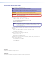
Conventions Used in this Guide
In this user guide, the following are used:
NOTE: A note draws attention to important information.
TIP: A tip provides a suggestion to make working with the application easier.
CAUTION: A caution indicates a potential hazard to equipment or data.
WARNING: A warning warns of things or actions that might cause injury, death, or
other severe consequences.
Commands are written in the fonts shown here:
^AR Merge Scene,,Op1 scene 1,1 ^B 51 ^W^C
[01] R 0004 00300 00400 00800 00600 [02] 35 [17] [03]
E X! *X1&* X2)* X2#* X2! CE}
NOTE: For commands and examples of computer or device responses mentioned in
this guide, the character “0” is used for the number zero and “O” represents the capital letter “o.”
Computer responses and directory paths that do not have variables are written in the font
shown here:
Reply from 208.132.180.48: bytes=32 times=2ms TTL=32
C:\Program Files\Extron
Variables are written in slanted form as shown here:
ping xxx.xxx.xxx.xxx —t
SOH R Data STX Command ETB ETX
Selectable items, such as menu names, menu options, buttons, tabs, and field names are
written in the font shown here:
From the File menu, select New.
Click the OK button.
Copyright
© 2012 Extron Electronics. All rights reserved.
Trademarks
All trademarks mentioned in this guide are the properties of their respective owners.
Contents
Introduction ......................................................1
About This Guide................................................. 1
About the DMP 44 LC Digital Matrix Processor..... 1
Features............................................................... 1
DMP 44 LC Application Diagram.......................... 4
Installation ........................................................5
Mounting the DMP 44 LC.................................... 5
Rear Panel Features and Cabling.......................... 5
USB Configuration port (front panel)................ 8
Operation...........................................................9
DMP 44 LC Operation.......................................... 9
Front Panel Operation........................................ 10
Rear Panel Operation......................................... 10
Power Cycle................................................... 10
Firmware Updates.......................................... 11
Reset Actuator and LED................................. 11
Digital Input Ports.......................................... 12
DSP Processing and Signal Flow......................... 14
Line Input Signal Chain.................................. 14
Mix Matrix..................................................... 15
Line Output Chain......................................... 15
Processor Blocks............................................. 15
Line Input Channels........................................... 16
Line (Input) Gain............................................ 16
Filter Block..................................................... 17
Setting bass and treble filters......................... 21
Configuring Groups....................................... 22
Configuring Bass and Treble Groups............... 24
Dynamics Processor........................................ 27
Mix Matrix......................................................... 33
Line Output Channels........................................ 37
Filter.............................................................. 37
Dynamics....................................................... 38
Volume.......................................................... 38
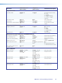
SIS Programming and Control........................39
Special Characters............................................. 42
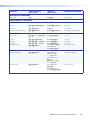
Command/Response Tables for DSP SIS
Commands....................................................... 46
Command/Response Tables for Audio SIS
Commands....................................................... 47
Symbol definitions......................................... 47
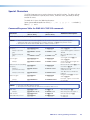
Special Characters............................................. 48
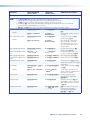
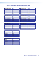
Table 1. Level Control and Mix-point Selection
Tables .......................................................... 50
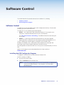
Software Control.............................................51
Software Control............................................... 51
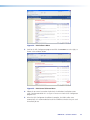
Installing the DSP Configurator Program........ 51
Install the USB Driver...................................... 53
DSP Configurator Program................................. 54
Starting the Program...................................... 54
Using the Program......................................... 55
Emulate Mode vs. Live Mode......................... 56
Synchronizing: Pull vs. Push............................ 56
Selecting Live Mode and Pushing or Pulling a
Configuration............................................... 57
Push Configuration - Advanced, Push Presets,
All................................................................. 64
Push Configuration - Advanced, Push Presets,
Selected........................................................ 66
Reference Information....................................67
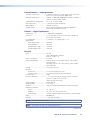
Specifications..................................................... 67
Part Numbers and Accessories............................ 69
Included Parts................................................ 69
Accessories.................................................... 69
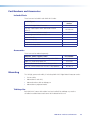
Mounting.......................................................... 69
Tabletop Use.................................................. 69
UL Rack Mounting Guidelines........................ 70
Rack Mounting.............................................. 70
Furniture Mounting........................................ 71
Firmware Loader................................................ 72
DMP 44 LC Hardware Reset Modes.................... 74
Connection Options........................................... 39
RS-232 Port................................................... 39
USB Port (front panel).................................... 40
DMP 44 LC-initiated Messages....................... 40
Using the Command/Response Tables............ 40
Error Responses............................................. 41
Command/Response Table Overview.................. 41
Command/Response Table for Basic SIS
Commands....................................................... 41
Symbol definitions............................................. 41
DMP 44 LC • Contents
v
DMP 44 LC • Contents
vi
Introduction
This section describes this guide and the DMP 44 LC, including:
•
About This Guide
•
About the DMP 44 LC Digital Matrix Processor
•
Features
•
DMP 44 LC Application Diagram
About This Guide
This guide contains installation, configuration, and operating information for the
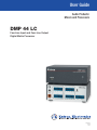
Extron DMP 44 LC Digital Matrix Processor, software controlled digital audio processor.
In this guide, the DMP 44 LC may also be referred to as “the DMP” or “device.”
About the DMP 44 LC Digital Matrix Processor
The DMP 44 LC is a standalone audio matrix processor with four line inputs and four line
outputs. Using high-quality 24‑bit A/D converters sampling at 48 kHz, input signals are
converted into the digital domain where Digital Signal Processing algorithms process and mix
the signals. The DMP 44 LC uses a matrix design providing audio signal processing available
in any of the input and output signal paths. A matrix mixer provides extremely flexible
architecture, allowing for versatile processing, mixing, and routing scenarios.
An RS-232 port on the rear panel, plus a USB port located on the front panel provide
convenient high-speed access. Three digital input ports permit connection of switches and
sensors to provide input to the system for triggering a variety of actions within the device.
The DMP 44 LC has no front panel controls, therefore all configuration of DSP processors
and the matrix mixer is performed using the Extron DSP Configurator™ program from a host
computer via the RS-232 or USB communication ports.
Two operational modes, Live and Emulate, allow a user to work offline from the device to
set up a configuration and create presets and group controls as needed before placing the
configuration in the DMP 44 LC. DSP Configurator settings developed offline can be saved
to disk as a job file that can be uploaded to the device at a later time, or can be transferred
directly to the device by switching to Live mode. Up to 16 full or partial presets and up to
16 group master controls can be created, loaded into and stored in the DMP 44 LC. Control
systems connected to the device by RS-232 can control a subset of DMP 44 LC functions
using Extron Simple Instruction Set (SIS™) commands.
Features
•
Consumer and professional audio compatibility — Line inputs provide gain settings
to accommodate consumer (-10 dBV) and professional (+4 dBu) operating line level
sources.
•
Inputs — Four balanced or unbalanced line on 3.5 mm, 6-pole captive screw
connectors.
DMP 44 LC • Introduction
1
•
Outputs — Four balanced or unbalanced line on 3.5 mm, 6-pole captive screw
connectors.
•
4x4 line level audio matrix mixer — The DMP 44 LC is a compact matrix processor
with DSP. It features four line level inputs that can be processed, mixed, and routed to
four line level outputs.
•
DSP audio signal processing — The DMP 44 LC provides digital signal processing on
all input and output paths.
•
24-bit/48 kHz analog-to-digital and digital-to-analog converters — High
performance converters preserve audio signal integrity in input and output signal
conversion, while maintaining latency under 1 ms.
•
Three digital input ports for remote triggering — Three configurable digital input
ports are provided, so that external switches and sensors can be connected to the
mixer for remote triggering of functions within the DMP 44 LC.
•
Building Blocks processor templates — A collection of pre-designed processor
templates optimized for a specific type of input or output device, such as microphones
and Extron speakers, with preset levels, filters, dynamics, and more. Flexible building
blocks are available on each I/O strip and allow system designers to fully customize
and save their own building blocks, further streamlining audio system design and
integration.
•
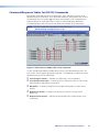
Console View with gain settings, metering, and routing in a single window —
An optional view within the DSP Configurator software that allows system designers
to see all gain settings and routing, together with live metering in a single window.
Console view provides overload indication, numeric values for levels, and also mute
status for each input, gain stage, mix point, and output, so that settings between
inputs and outputs can be easily compared and adjusted in one view.
•
Live and Emulate operation modes with configuration file saving — Allows
settings to be configured offline, then uploaded to the DMP 44 LC. The software also
backs up configurations from the device for archiving.
•
Low latency DSP processing — The DSP engine supports an array of concurrent
audio processing within an audio channel and across multiple channels, while
maintaining extremely low latency from input to output.
•
DSP Configurator Software — Powerful, user-friendly PC-based software tool for
managing all audio operations of the DMP 44 LC. The software enables complete
setup and configuration of digital audio processing tools, as well as routing and
mixing.
•
Intuitive Graphical User Environment — The DSP Configurator software features
a graphical user environment with a clear view of all input and outputs, audio
processing blocks, routing, mix-points, and virtual routing in a single window. This
allows a designer or installer to quickly view all audio activities without having to
access multiple windows or menus.
•
SpeedNav™ keyboard navigation — SpeedNav enables user-friendly,
keyboard-based navigation of the DSP Configurator software without the need for a
mouse or touchpad. Using keyboard navigation keys and shortcuts, a user can access
any input or output, mixing points, and all audio DSP tools. Using only the keyboard
for software access can help expedite audio system setup and commissioning while
on-site using laptop.
•
Copy and paste for processing blocks — To help speed up audio system design
and setup, parameter settings can be quickly copied between individual processing
blocks or identical groups of blocks within the graphical user environment, using
conventional cut-and-paste commands.
DMP 44 LC • Introduction
2
•
16 DSP Configurator presets — Using the DSP Configurator software, parameters
for DSP processing, signal levels, or audio routing can be saved as presets. These
settings can be saved for the entire system, or any selected group of inputs, outputs,
mixing points, and DSP blocks.
•
Group masters — The DMP 44 LC provides the capability to consolidate gain or
mute control throughout the system. Any gain or mute block within the graphical
user environment can be selected and added to a group master, which can then be
controlled by a single master fader and mute control. Sixteen group master controls
are provided. Each group master can have up to eight members.
•
Soft limits provide optimal group master adjustment range — The group master
volume range can be limited using soft limits to maintain optimal minimum and
maximum levels when using external volume control. This prevents operators from
over- or under-adjusting levels.
•
Flexible control options — The DMP 44 LC can be controlled using the
DSP Configurator software and a PC connection to the RS-232 serial port, or to the
USB 2.0 port on the front panel.
•
Front panel USB configuration port — Enables configuration without having to
access the rear panel.
•
RS-232 serial control port — Using serial commands, the DMP 44 LC can be
integrated into third-party control systems using SIS commands.
•
Versatile mounting options — Rack-mountable 1U, quarter rack width metal
enclosure.
DMP 44 LC • Introduction
3
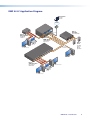
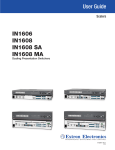
DMP 44 LC Application Diagram
TouchLink™
VCR
DVD
DOC
CAM
P
LAPTO
PC
ON
OFF
AY
DISPL
MUTE
N
SCREE
UP
Control
System
N
SCREE
DOWN
TCP/IP
®
100
INPUT
IR
RELAY
LINK
3
ACT
1
3
1
COM
RX
IPL
TX
250
4
3
2
1
4
2
1
2
R
4
2
3
C
4L
P4
DM
T
SE
RE
T
L/
TPU
RO
OU
NT R
CO WE
PO
T
OU
2
S
UT
INP
UTS R
INP 3
IO L
1
L
4
R
/MIX
AUXNO
MO
A
B
.5A
MA
1
2
R
L
X
O
U
T
P
U
T
S
V
12
AUD
2
2
1
A
1
I
N
P
U
R
WE T
PO
S
2 VG
S 10
ML
Extron
MLS 102 VGA
Tx
1
2
3
Extron
XPA 1002
Rx
I IN
-232
DIG
RS-232
RS
Power Amplifier
4
3
4
02
A 10
XP
3
PUT2
OUT
1
MediaLink
Switcher
OTE
ING
mA
REM
50
MUTE
10V VOL/
V AX
12 M
0.3A
SS
2 WIR
CLA
UTS2
INP
1
Extron
DMP 44 LC
EL
LEV
1
0Hz
, 50-6
0.5A
240V
100-
US
T
17T O
C
ED IDE
LISTIO/V TUS
/
ITER T
AUD ARA
LIM TEC
APP
PRO
NAL
SIG
1
2
DBY
STAN
2
0
0
Digital Matrix
Processor
Extron
SI 26
Laptop with
VGA Out
PC with VGA Out
IA
Two Way
Surface
Mount
Speakers
Line Output for
Podcast/Recording
US
PL
8 DV
SW
-SW
TO
R
L
DIO
/ AU
I-D UT
DV OUTP
TE
/ AU
MO
RE
AS
Tx
Rx
8
7
6
TS
I/
DIO
INPU
5
AU
PC
DV
4
3
2
1
R
WE
PO
X
12V MA
A
0.4
Extron
SW8 DVI A Plus
DVI Switcher
With Audio
PC with DVI Out
Laptop with
DVI Out
PC with DVI Out
DMP 44 LC • Introduction
4
Installation
This section describes the installation of the DMP 44 LC, including:
•
Mounting the DMP 44 LC
•
Rear Panel Features and Cabling
Mounting the DMP 44 LC
The 1U high, quarter rack width, 3.0 inch deep DMP 44 LC Digital Matrix Processor can
be:
•
Set on a table,
•
Mounted on a rack shelf,
•
Mounted under a desk or tabletop, or
•
Mounted on a projector bracket.
See “Mounting” in the “Reference Information” section for detailed mounting
instructions.
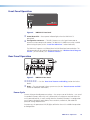
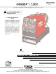
Rear Panel Features and Cabling
1
INPUTS
2
OUTPUTS
1
2
DMP 44 LC
7
RESET
POWER
12V
0.3A MAX
3
4
3
4
RS-232 DIGI IN
Tx Rx
1
2
Figure 1.
3
4
1
5
2
3
6
DMP 44 LC Rear Panel
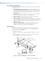
a Power connector — Connect the included 12 VDC external power supply into the
2-pole 3.5 mm captive screw connector. Be careful to observe the correct polarity.
DMP 44 LC • Installation
5
2-Pole Captive Screw
Connector
Tie Wrap
3/16”
(5 mm) Max.
SECTION A–A
Smooth
Ridges
A
A
Power Supply
Output Cord
Figure 2.
Power Supply Wiring
WARNING: The two power cord wires must be kept separate while the power supply is plugged
in. Remove power before wiring.
CAUTIONS: • Always use a power supply supplied by or specified by Extron. Use of an
unauthorized power supply voids all regulatory compliance certification and may
cause damage to the supply and the end product.
• Unless otherwise stated, the AC/DC adapters are not suitable for use in air
handling spaces or in wall cavities. The power supply is to be located within the
same vicinity as the Extron AV processing equipment in an ordinary location,
Pollution Degree 2, secured to the equipment rack within the dedicated closet,
podium or desk.
• The installation must always be in accordance with the applicable provisions of
National Electrical Code ANSI/NFPA 70, article 75 and the Canadian Electrical
Code part 1, section 16. The power supply shall not be permanently fixed to
building structure or similar structure.
CAUTION:
When connecting the power supply, voltage polarity is extremely important.
Applying power with incorrect voltage polarity could damage the power supply and
the DMP 44 LC. Identify the power cord negative (ground) lead by the ridges on the
side of the cord or a black heat shrink wrapping around it.
CAUTION:
The length of the exposed (stripped) copper wires is important. The ideal length
is 3/16 in (5 mm). Longer bare wires can short together. Shorter wires are not as
secure in the direct insertion connectors and could be pulled out.
Do not tin the stripped power supply leads. Tinned wires are not as secure in the
captive screw connectors and could be pulled out.
NOTE: To verify the polarity before connection, check the no load power supply output with a
voltmeter.
Use the supplied tie-wrap to strap the power cord to the extended tail of the connector.
NOTE: To avoid losing adjustments when configuring the DMP 44 LC via
SIS commands issue a 2FF or if using the DSP Configurator, select
Tools > Save Changes to Device to store the latest changes to the
device. Wait several minutes after saving the adjustments before disconnecting
power.
DMP 44 LC • Installation
6
b Power/Reset LED — The green LED indicator duplicates the front panel LED
operation (see the “Reset Actuator and LED” section for additional information).
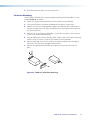
c Line 1-4 input connectors — 6-pole 3.5 mm double-stacked captive screw
connectors accept balanced or unbalanced mono line level signals. Line inputs
provide gain settings to accommodate consumer (-10 dBV) and professional (+4 dBu)
operating line level sources. Up to four mono line inputs, balanced and unbalanced
in any combination may be connected to these inputs (see the following diagram for
wiring instructions).
Audio Input Wiring
Tip
Ring
Sleeve
Tip
Sleeve
Unbalanced Input
Balanced Input
Figure 3.
Wiring Balanced or Unbalanced Line Inputs
d Mono output connectors (1-4) — 6-pole 3.5 mm captive screw connectors provide
balanced or unbalanced connections for mono line level output signals.
Audio Output Wiring
Tip
Ring
Sleeve
Tip
NO Ground Here
Sleeve
Balanced Output
Figure 4.
CAUTION:
Unbalanced Output
Output Connector Wiring
Connect the sleeve to ground (Gnd). Connecting the sleeve only to
a negative (-) terminal will damage the audio output circuits.
e RS-232 connector — A 6-pole 3.5 mm captive screw connector for bidirectional
RS-232 (±5 V) serial control. Default baud rate is 38400.
RS-232
DIGI IN
Tx Rx
Tx Rx
RS-232
Device
Do not tin
the wires!
Transmit (Tx)
Receive (Rx)
Ground ( )
1
2
3
Bidirectional
Transmit (Tx)
Receive (Rx)
Ground ( )
Figure 5. RS-232 Wiring
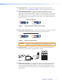
f Digital input connector — A 6-pole 3.5 mm captive screw connector (shared with
the RS-232 port) provides three configurable input ports allowing connection to
various devices including motion detectors, alarms, buttons, photo (light) sensors,
and temperature sensors. This connector shares a common ground with the RS-232
connector (e).
DMP 44 LC • Installation
7
The digital input port is used to monitor TTL level digital signals. Voltages greater than
2 V indicate a logic “high” signal while voltages less than .8 V indicate a logic “low.”
NOTE: These ports are configured via DSP Configurator (see the “Digital input
ports” section for additional information).
Do not tin the wires!
_
1
2
3
Digital I/O Wiring
Both the RS-232 and digital input connectors may be used simultaneously by using a
6-pin captive screw connector with two wires sharing the same ground connector (see
the diagram below).
RS-232
Tx Rx
DIGI IN
1
2
3
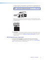
g Reset button — The recessed reset button is used to access various modes of resets.
The single green power LED on both the front and rear panels indicates what mode
of reset was accessed (see the “DMP 44 LC Hardware Reset Modes” section for
additional details).
USB Configuration port (front panel)
A front panel configuration port uses an Extron USB A Male to USB Mini B Male
Configuration Cable, 26-654-06 for connection to a PC computer via the USB port.
The DMP USB driver must be installed prior to using the port (see the “Install the USB
Driver” section for USB driver installation details).
DMP 44 LC • Installation
8
Operation
This section describes the operation of the DMP 44 LC, including:
•
DMP 44 LC Operation
•
Front Panel Operation
•
Rear Panel Operation
•
DSP Processing/Signal Flow
•
Processor Blocks
•
Mix Matrix
•
Line Output Channels
DMP 44 LC Operation
The DMP 44 LC does not have physical controls. Configuration and operation are
accomplished using a PC running Windows® XP or better and the DSP Configurator
software (available on the included disc or at www.extron.com), or the Extron Simple
Instruction Set (SIS) using HyperTerminal or DataViewer.
The DMP 44 LC is configured for immediate operation, with each input routed to its
respective output (input 1 routed to output 1, input 2 routed to output 2, and so on).
While these settings allow the device to pass audio when first connected, it rarely meets
the needs of most applications. The DMP 44 LC can be fully configured using the DSP
Configurator software.
The DSP Configurator software, when first launched, gives you a blank configuration with
no processing and no mixing or routing. All gain stages are set to “unity gain,” or
0 dB of gain. Input and output gain stages provide metering in dBFS that will assist you in
configuring the device for optimal operation. The DMP 44 LC is a digital device, therefore
optimal operating levels are close to 0 dBFS without ever going over 0 dBFS (0 dB “full
scale” on the input or output meters). Levels above 0 dBFS cause clipping, which is always
audible on a digital device.
All gain stages in the DMP 44 LC are mono. Gain may also be controlled using a Group
master, which is configured with the DSP Configurator software. Group masters can
be used to group multiple gain or mute controls, group multiple bass or treble boost/
cut controls, gang two gain or mute controls for stereo operation, or even to control a
single gain point. Soft limits can be applied to group masters. Sometimes a particular gain
range may be too great, allowing for settings that are too loud or too soft, while in some
instances the loudest settings may cause feedback or clipping. Soft limits can be used to
limit the gain range for smoother operation.
Finally, the DMP 44 LC provides a comprehensive set of DSP processing tools. Use the filter
tools to shape the tonal quality of your source material or EQ the room to compensate for
acoustic gain. Use the dynamics processors for level control or system protection. The
DMP 44 LC is a versatile matrix processor for many applications.
DMP 44 LC • Operation
9
Front Panel Operation
CONFIG
DMP 44 LC
DIGITAL MATRIX PROCESSOR
1
2
Figure 6.
DMP 44 LC Front Panel
a Power/Reset LED — Green power indicator lights when the DMP 44 LC is
operational.
b Configuration connector — The USB 2.0 port uses a mini type-B connector to
connect to a host computer for control. The DMP 44 LC USB driver must be installed
prior to using the port (see the “Install the USB Driver” section for details).
The DMP 44 LC appears as a USB peripheral with bi-directional communication. The
USB connection can be used for software operation (see “Windows-based Program
Control”), and SIS control, (see “Software Control”).
Rear Panel Operation
1
INPUTS
2
OUTPUTS
1
2
DMP 44 LC
7
RESET
POWER
12V
0.3A MAX
3
4
3
4
RS-232 DIGI IN
Tx Rx
1
2
3
Figure 7.
4
5
1
2
3
6
DMP 44 LC Rear Panel
a b c d e f — See the “Rear Panel Features and Cabling“section for further
details.
g Reset — The reset actuator initiates system reset (see the “Reset Actuator and LED”
section for additional information).
Power Cycle
Current mixing and audio processor settings — the current state of the device — are saved
in nonvolatile memory. When the unit is powered off, all settings are retained. When the
unit is powered back on, it recalls settings from the nonvolatile memory. If a configuration
was in process during the power down, these saved mix, audio level, and audio DSP
processor settings become active.
On power up, the power/reset LED (b) lights solid when the unit is available for operation
or configuration.
DMP 44 LC • Operation
10
Firmware Updates
The firmware of the DMP 44 LC can be updated through USB or RS-232 connection. The
user can obtain new firmware from the Extron website. After obtaining the new firmware,
upload it to the unit using the Firmware Loader option in the DSP Configurator program
(see the “Software Control” section), or using the Extron standalone Firmware Loader
application available on the included disc or at www.extron.com.
Reset Actuator and LED
A recessed button on the rear panel (g) initiates two reset modes. The green front panel
LED (b) and rear panel (b) LED blink to indicate the reset modes as described in the
following section. See the previous front and rear panel diagrams.
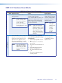
Hardware Reset Modes
With power on, when the reset button is held down the front and rear panel LEDs pulse
(blink) every three seconds and put the unit in a different reset mode. The DMP 44 LC
defaults back to the base firmware that shipped with the unit from the factory, allowing
the user to recover a unit that has incorrect code or updated firmware running.
NOTE: Control software may not function correctly if using an earlier firmware
version.
MODE 1 — Firmware reset: Disconnect power to the DMP 44 LC. Press and hold the
reset button while applying power to return the firmware to the version shipped with the
unit from the factory. This allows recovering a unit with incorrect or corrupt firmware. All
user files and settings are maintained.
MODE 5 — Factory default reset: With power on, press and hold the reset button until
the reset LED blinks 3 times (~9 seconds). Each flash will last for 0.25 seconds. Release,
then momentarily (<1 second) press the reset button to return the DMP 44 LC to factory
default conditions. If the second momentary press does not occur within 1 second, the
reset is exited.
The default (reset) state of the device is:
•
Inputs 1 to 4 are mixed to corresponding outputs 1 to 4 (all other mix-points are set to
0 dB gain and muted).
•
All inputs are active (unmuted, 0 dB gain).
•
All outputs are active (unmuted, 100% volume).
•
No inserted or active DSP processing.
•
Group master memory is clear (empty).
•
No presets.
•
Digital input ports are not active and not configured.
DMP 44 LC • Operation
11
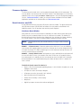
Digital Input Ports
The three-pin Digital Input port is used to monitor or drive TTL level digital signals. The
port consists of three input pins with the fourth pin being used as a ground providing
three inputs total. The DSP Configurator software provides a selection of functions to be
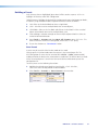
loaded to the DMP 44 LC (see the “Software Control” section).
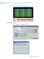
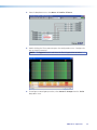
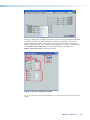
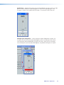
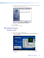
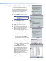
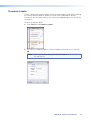
1. From the menu bar, click Tools > Configure Digital Inputs to access the
Configuration utility.
2. Select the digital input to configure.
DMP 44 LC • Operation
12
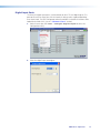
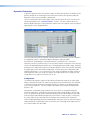
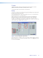
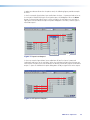
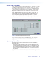
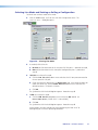
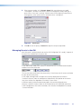
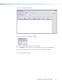
3. Select the event or “trigger” to configure the input.
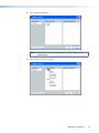
4. Select the action that results when the trigger occurs.
5. Select the group to act upon when the trigger event occurs.
6. Select Apply to accept the changes.
DMP 44 LC • Operation
13
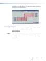
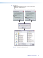
DSP Processing and Signal Flow
The diagram below shows the signal flow and DSP processing per signal chain. Signal
chains and the matrix are described in the following sections.
All signal routing, processing, and level control (gain/trim/volume), are accomplished using
software control from a PC connected to the DMP 44 LC via the USB configuration port
or the RS-232 port. The DSP Configurator program provides complete control while SIS
commands provide more limited control.
This section describes the signal processing including parameter ranges, and how to
mix inputs and outputs using the DSP Configurator control program. To install the DSP
Configurator program (see the “Software Control” section).
Line Input Signal Chain
Input signal chain GUI elements from left to right are as follows:
•
Gain (GAIN) — Mono gain control with a range from -18 to +24 dB includes a mute
button. Step resolution is 0.1 dB. A polarity switch (+ or -) is provided. Gain control is
provided pre-meter and mute control is provided pre-meter.
•
Filter (FILT) — Up to three filters can be inserted in any combination of High Pass,
Low Pass, Bass & Treble shelving (tone), or Parametric Equalizer.
•
Dynamics (DYN) — One compressor per block per channel. Dynamics processors vary
the dynamic level (the range of loudest to softest signals).
•
Ducking (DUCK) — One ducker per block, per channel. Each ducker can function as
either a source or a target. Three levels of priority are available, where a ducker can
function as both a source and a target (as an example, one source may be ducked by
another source, and also trigger ducking on program channels).
•
Gain (GAIN) — One pre-mixer gain control per channel with a range of -100 dB to
+6 dB. The step resolution is 0.1 dB.
DMP 44 LC • Operation
14
Mix Matrix
The line input process routes incoming signals through a mix matrix to the line outputs.
The mix matrix contains 16 mix-points, one for each input to each output bus with each
mix-point containing a single fader with a range of -24 dB to +12 dB, plus a mute control.
The step resolution is 0.1 dB.
Line Output Chain
Line output chain elements from left to right are as follows:
•
Trim (TRIM) — One post-mixer mono gain control per channel with a range of -12 dB
to +6 dB. The step resolution is 0.1 dB.
•
Filter (FILT) — Up to nine frequency filters can be inserted in any combination of High
Pass, Low Pass, tone (Bass & Treble shelving), or Parametric Equalizer.
•
Dynamics (DYN) — One limiter per block per channel. The limiter prevents clipping
and protects a system against component or speaker damage.
•
Volume (VOL) — One output volume control per channel with a range of -100 dB to
0 dB. The step resolution is 0.1 dB. Gain control is provided pre-meter. Mute control is
provided post-meter. A polarity switch (+ or -) is provided.
Processor Blocks
Processor blocks are placed in the signal chain to perform specific tasks. There are level
control blocks, signal processor blocks and mix-point matrix blocks (with level control).
Level control processors do not have to be inserted, they are always active. The following
sections provide details of navigation, menus, and other interface operations. The
processor blocks, while performing different functions, have several common elements.
•
Insert — All blocks (except level controls) may be inserted by right-clicking on the
desired box and selecting from the context menu or by double-clicking and making a
selection.
•
Remove a process — Active processors can be removed by right‑clicking on the box
and selecting Delete or by selecting the block and pressing delete on the keyboard.
This sets the parameters back to default and removes or “deactivates” the block. An
active processor may be replaced by right-clicking and inserting a new processor. A
warning appears to indicate the previous processor is about to be replaced.
•
Mute — When a level block (gain, trim or volume) is muted, all signal flow is blocked.
When mute is active a red mark appears in the lower left of the block. Mix-point mute
is indicated by shadowing the mix-point.
•
Bypass — When bypass is active, signal flow passes through the block without
processing, regardless of the settings. When bypass is removed, the signal will be
processed according to the parameter settings. A red mark appears in the lower left of
the block (shown below) to indicate it has been inserted, but is currently bypassed.
DMP 44 LC • Operation
15
Line Input Channels
There are four (4) mono line input channels. Channel controls and processing blocks
described in the following sections are identical for each of the four inputs.
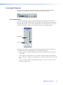
Line (Input) Gain
Line inputs provide gain settings to accommodate consumer and pro line level sources.
Each input channel gain block provides a mono long-throw fader for gain and attenuation.
Range for the control is -18 to +24 dB. Step resolution is 0.1 dB. Adjustments are made
using the slider or by entering the desired dB level directly into the indicator box.
Fader Handle
Gain Level
Clicking the fader handle or clicking within the fader area brings focus to the fader. The
input signal level can be adjusted using any of the following methods:
•
Direct adjustment. Click and hold the fader handle, then drag it to the desired level in
0.1 dB steps.
•
Click or tab to the fader handle, then <up arrow> or <down arrow> to the desired
level in 1 dB steps. <Page Up> and <Page Down> increases or decreases level in 10 dB
steps.
•
Click in or tab to the signal level readout field. Type a new value, then press <Enter>
or <Tab> to another area.
DMP 44 LC • Operation
16
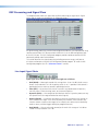
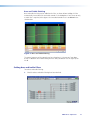
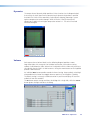
Filter Block
Each line input channel filter block allows a total of five filters.
The first filter is inserted from a processor list that appears when the block is
double‑clicked or via a context window/processor list when the block is right‑clicked.
After the processor is inserted, double-clicking opens the setup dialog box.
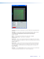
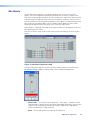
Figure 8. Filter Block Dialog Box
Additional filters are inserted by opening the filter block dialog box, then selecting a filter
type from the drop-down filter selection list. All filter parameters are modified via the Filter
block dialog box. Each filter loads with all applicable default parameters displayed to the
right of each drop-down filter selection list.
DMP 44 LC • Operation
17
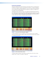
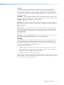
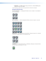
Figure 9. Filter Dialog Box, Filters Added
Within the dialog box, a filter is focused when a filter type is inserted, or is focused by
clicking the filter number to the left of the filter selection drop-down list. Note how filter 3
in the figure below is highlighted in yellow, indicating it is the filter in focus. The results of
the filter in focus (independent of other filters) shows in the graph as a dotted line of the
same color as its filter row when bypassed. When active (not bypassed), the line is solid.
Figure 10.Filter Dialog Box, Filter Not Bypassed
When multiple filters are enabled, the graph indicates the focused filter result
(independent of other filters) in the color of the filter row in the type/parameters table.
The composite response of all filters is displayed in red.
Above the graph, each filter has a "handle" (circled in red above) placed directly
above the cutoff or center frequency whose number corresponds to the filter number
(outlined in red). Clicking a handle or clicking the table row brings focus to that filter.
Click+hold+dragging the handle horizontally changes the cutoff or center frequency to a
new position on the x axis.
DMP 44 LC • Operation
18
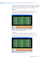
Parametric (Equalizer)
Up to three parametric filters can be placed in the filter box at one time. Each may be set
to a different frequency creating a 3 band parametric equalizer. The control will boost or
cut the center frequency, and by changing the Q value, the range of affected frequencies
can be widened or narrowed around the center frequency. In general, the higher the Q,
the narrower the affected bandwidth.
To demonstrate how Q affects the filter, see the following filter block below containing
three parametric filters centered at different frequencies but with the same Q of 1.0. The
filter in focus (b) has a center frequency of 1000 Hz boosting that frequency +12 dB over
a Q of 1.0. Note the markers on either side of the peak frequency are at 200 Hz on the
left and 5000 Hz on the right, a bandwidth of about 4800 Hz.
Figure 11.Parametric Filter Dialog Box, 1000 Hz
The above dialog box shows the frequency curve for the single active filter. To add its
effect to the overall frequency response, remove the bypass on the other filters, as shown
in the following illustration.
Figure 12.All Parametric Filters Active
The overall frequency response is now shown as a solid red line with the filter in focus,
located in row 2, shown in the color of its table row.
DMP 44 LC • Operation
19
The parametric filter allows frequency selection accurate to 0.1 Hz and either 6 or 12 dB of
slope. Notice at the specified frequency (100 Hz) the signal is 3 dB down, typical operation
for high pass filters. The 3 dB down point will remain constant regardless of the slope
setting. Only the steepness of the frequency attenuation curve will change.
High Pass
The high pass filter is the opposite of the low pass filter. All frequencies below the
specified frequency are attenuated allowing higher frequencies to pass.
In the figure below, the frequencies lower than the specified frequency, 1 kHz, are
attenuated leaving the higher frequency response flat.
Figure 13.High Pass Filter Response Curve
Low Pass
The low pass filter is the opposite of the High Pass filter. All frequencies above the
specified frequency are attenuated allowing lower frequencies to pass.
In the figure below, the frequencies higher than the specified frequency, 10 kHz, are
attenuated leaving the lower frequency response flat.
Figure 14.Low Pass Filter Response Curve
DMP 44 LC • Operation
20
Bass and Treble Shelving
Bass and treble shelving may be added to the filter, as shown below. Adding this filter
automatically inserts both bass and treble controls in the dialog box. If only a bass or only
a treble filter is required, either bypass the unneeded control or set it to unused in the
selection box.
Figure 15.Bass and Treble Shelving
The corner frequency of the controls may be selected to 0.1 Hz accuracy. Two slopes,
6 and 12 dB/octave are available along with the ability to boost or cut the signal up to
24 dB.
Setting bass and treble filters
To set bass and treble filtering:
1. Check that bass and treble filtering have been defined.
DMP 44 LC • Operation
21
2. Specify bass and treble filters if necessary.
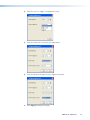
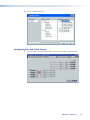
Configuring Groups
1. From the View menu, select Group Controls.
2. To add a new group, select Add a Group.
DMP 44 LC • Operation
22
3. Select a group to configure.
NOTE: To configure Bass and Treble groups, see “Configuring Bass and
Treble Groups.”
4. Select a control type for the group.
DMP 44 LC • Operation
23
5. Define the group members.
Configuring Bass and Treble Groups
1. From the main DSP Configurator screen, select the Filters block, as shown below.
DMP 44 LC • Operation
24
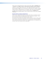
2. From the drop down menu select Bass & Treble Filters.
3. Double-clicking the Filters processor opens the configuration screen. Configure the
bass and treble parameters.
NOTE:The Bypass button is red when the filter is bypassed or not active.
4. To configure a control group member, select Control Groups from the Tools
drop-down menu.
DMP 44 LC • Operation
25
5. Select the Bass or Treble control group.
6. Select the group members.
7. Repeat steps 5 and 6 for the unselected control group (Bass or Treble).
DMP 44 LC • Operation
26
Dynamics Processor
A dynamics processor alters the dynamic range, the difference between the loudest to the
quietest portions of an audio signal. Each input channel offers one dynamics processor
block that, when inserted, provides a compressor.
To insert a processor into an empty block, select from the processor menu (see the Insert
Compressor option in the “Processor Blocks” section). The menu appears when the
block is double-clicked, or is accessed from a context menu that appears when the block is
right-clicked (see the diagram below).
Once the processor has been inserted, individual processor parameters can be changed in
the dialog box, which is accessed by double‑clicking the processor block.
All parameters are displayed in a text box and have a resolution of 0.1 increments.
Parameters can be set by direct entry in the text box to replace existing text, then pressing
<Enter> or tabbing/clicking to another area. Threshold, gain/attenuation, target, and ratio
parameters have adjustment points on the graph display. Use the mouse to click and drag
the graph point to the desired destination/value. All time values have a horizontal slider
allowing adjustment in 1 ms increments by either a click and drag of the slider handle, or
focusing on the slider, then using <left arrow> and <right arrow> keys (<Page up> and
<Page down> keys adjust in increments of 10 ms).
Compressor
The compressor regulates signal level by reducing the dynamic range of the input signal
above a specified threshold. The input level to output level ratio determines the reduction
in the dynamic range beyond the threshold setting. For example, in the diagram below,
with a ratio setting of 2:1, for every 2 dB of input above the threshold, the compressor
outputs 1 dB.
Compression is commonly used to contain mic levels within an acceptable range for
maximum vocal clarity. A compressor can also make softer sounds louder in one of two
ways. The dynamic range can be reduced by compressing the signal above the threshold
while raising the post‑compressor gain/trim (referred to as "make‑up gain"). Alternately,
the input signal can be increased while the compression ratio above the threshold is
increased correspondingly to prevent clipping. Both techniques have the effect of making
louder portions of a signal softer while at the same time increasing softer signals to raise
them further above the noise floor.
DMP 44 LC • Operation
27
Compression can also be used to protect a system or a signal chain from overload similar
to a limiter.
Threshold — The input signal level above which compression begins (subject to attack
time) and below which compression stops (subject to hold and release time).
Threshold level can be adjusted from -80.0 to 0.0 dB in 0.1 dB increments.
Default is -30.0 dB.
Ratio — The input signal level reduction when compression is engaged.
Ratio can be adjusted from 1.0 to 100.0 in 0.1 increments.
Default is 2.0:1.
Attack Time — Adjusts the time delay for compression to engage after the input signal
level reaches or exceeds the threshold level. Attack time can be adjusted from 0.0 to 200.0
ms in 0.1 ms increments.
Default is 5.0 ms.
Release Time — Adjusts the time it takes to return the signal to normal (unprocessed)
levels after the signal no longer exceeds the threshold level setting. Release time begins
only after hold time is reached. Release time can be adjusted from 10 to 1000.0 ms in
0.1 ms increments.
Default is 100.0 ms.
Soft Knee — Click the Soft Knee check box to smooth and soften the transition from
uncompressed to compressed output levels. There are no adjustments.
DMP 44 LC • Operation
28
Limiter
The limiter restricts the input signal level by compressing its dynamic range above a
specified threshold. The limiter is most commonly used to prevent clipping, protecting
a system against component or speaker damage. While the limiter is closely related to
the compressor, it applies a much higher compression ratio of ∞:1. The ratio is fixed and
cannot be changed.
Threshold — The input signal level above which limiting begins (subject to attack time)
and below which compression stops (subject to hold and release time). Threshold level can
be adjusted from -80.0 to 0.0 dB in 0.1 dB increments.
Default is -10.0 dB.
Attack Time — Adjusts the time delay for limiting to engage after the input signal level
reaches or exceeds the threshold level. Attack time can be adjusted from 0.0 to 200.0 ms
in 0.1 ms increments.
Default is 2.0 ms.
Release Time — Adjusts the time it takes to return the signal to normal (unprocessed)
levels after the signal no longer exceeds the Threshold level setting. Release time begins
only after hold time is reached. Release time can be adjusted from 10 to 1000.0 ms in
0.1 ms increments.
Default is 50.0 ms.
Soft Knee — Click the Soft Knee check box to smooth and soften the transition from
uncompressed to compressed output levels. There are no adjustments.
Ducking
Ducking provides a means to duck, or lower the level of one or more input signal targets
when a specified source must take precedence. Ducking lasts for the duration of the
ducking source signal (plus hold and release time) and restores the duck targets original
level once the ducking source signal has ceased.
Ducking may be useful when:
•
Program material needs to attenuate in order to accentuate the voice of a narrator,
•
One microphone is used by a chairman or master of ceremonies, and needs to have
priority over other mics, program material, or both, or
•
A paging mic must attenuate all other signals.
Ducking processor blocks are individually inserted from a context menu, as shown in the
following figure. Only a ducking source needs to be inserted. Ducking targets are enabled
from the Ducker Configuration dialog box.
DMP 44 LC • Operation
29
Ducking is configured in a window which opens when an active ducking processor block
is double-clicked (see the following diagram). Ducking can be globally set up from a
single configuration window, which opens when any of the active ducking processor
blocks are double-clicked. When a ducking processor block is inserted, it is automatically
set to Enable Source Mic/Line. All inactive ducking processor blocks have
Enable Source Mic/Line unchecked by default.
1
5
2
3
6
4
Figure 16.Ducker Configuration Dialog
Any of the four inputs can be ducking sources. Any or all of the remaining inputs can be
targets.
DMP 44 LC • Operation
30
Ducking Configuration Dialog
a
Current source indicator
Shows the selected input. Ducker settings affect the input channel shown here. When
a ducker dialog is opened for a channel, the current source defaults to that channel.
The current source can also be selected via the priority readout/source selector (see the
following figure).
b
Enable source mic/line checkbox
When checked, ducking is enabled for the current source and the ducker processor
block is lit. When unchecked, ducking is disabled for the current source and the ducker
processor block is unlit.
c
Duck
Shows all potential input targets. Only inputs that are checked will be ducked. The current
source is not available as a target (a source cannot duck itself). If the current source has
been designated as a target of another input channel, that input channel is not available
(a target cannot be the source).
d
Settings
Used to configure the parameter settings for the ducker source. When a ducker block is
copied, these settings are transferred.
Threshold — Sets the input signal level, in dB, the ducking source must exceed
before ducking begins. If ducking does not occur soon enough to avoid loss of
speech or program material from the ducking source, decrease this setting. If ducking
occurs too soon, allowing background noise to trigger ducking, increase the setting.
The range is -60 to 0 dB in 1 dB increments.
Default is -30 dB.
Attack Time — Adjusts the time to duck the targets once the threshold is exceeded.
The range is 0 to 3000 milliseconds in 1 millisecond increments.
Default is 1 millisecond.
Hold Time — Determines the time, in milliseconds, after a ducking source signal
drops below the threshold before release time engages.
The range is 0 to 10000 milliseconds in 1 millisecond increments.
Default is 1000 milliseconds (1 second).
Release — Determines the time, in milliseconds, after the ducking source level is
below the threshold and the hold time is met, the ducking targets take to restore
signal levels.
The range is 10 to 10000 milliseconds in 1 millisecond increments.
Default is 1000 milliseconds (1 second).
e
Priority
Displays the hierarchy of ducking source to duck targets. Priority levels are displayed in tree
fashion. Input channels that are targets being ducked by a source are shown as indented
below the source. Any input channel displayed in the tree is an active link. Click any input
channel to select that channel as the current source. The current source indicator (a)
reflects the selected input channel.
DMP 44 LC • Operation
31
f
By (dB)
Individual attenuation settings for each duck target in dB. The default is 20.0 dB. If
additional attenuation of the targets is required, increase this value.
The attenuation range is 80.0 to 0.0 dB in 0.1 dB increments.
Priority
In some cases, multiple levels of ducking may be required enabling an input source to take
precedence over all but one other input.
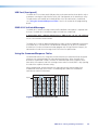
In the example below inputs 2 and 3 are set to duck when input 1 has a signal above the
ducking threshold. Input 2 is set to duck input 4.
Notice the priority tree in the illustration below (d). The inputs are arranged by their
priority status. Input 1 has inputs 2 and 3 under it, therefore, if input 1 exceeds the
threshold, it will trigger inputs 2 and 3 to duck. Similarly, input 2 has input 4 under it.
Therefore, if input 2 exceeds the threshold, it will trigger input 4 to duck. Since input 2 has
input 4 under it, input 1 triggers inputs 2, 3 and 4.
2
4
3
1
Figure 17.Ducker Configuration, Input Priority
Ducking attenuation is not additive. When an input target is ducked, regardless of how far
down the priority line it is, the maximum attenuation is what is set in the by: column near
the center of the dialog box.
DMP 44 LC • Operation
32
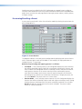
Mix Matrix
The DSP architecture contains a mix matrix that connects the line inputs to the line
outputs. The DSP Configurator GUI provides control of the mix matrix, used to set mix
levels from the post processing inputs, to each line output bus. Each of the four line inputs
is connected to a mix‑point for each of the four line outputs. In general, mix levels are set
relative to each other, achieving a desired blend of input signals at an optimal output level,
close to, but not exceeding 0 dBFS at the line output Volume block level meter (while
accounting for processing that may occur in the line output signal chain).
Shown below is a drawing of the DMP 44 LC represented in DSP Configurator, with a red
box indicating the mix matrix.
From the mix matrix, any or all of the four inputs may be routed to any or all of the four
outputs.
Mix Points
Figure 18.Mix Matrix (Outlined in Red)
Clicking a mix-point brings focus to that mix-point. Double-clicking a mix-point opens a
configuration dialog window, as shown below, with the following components:
•
Mono Fader — Sets mix level to the output bus. Gain range is -24 dB to +12 dB.
Fader behavior is identical to the input channel gain block described in the line input
section with the exception that coarse adjustment <Page up> or <Page down>
increases or decreases in 5 dB increments.
•
Mute — Mutes and unmutes the signal to the output bus.
DMP 44 LC • Operation
33
•
OK/Cancel — Click OK to accept changes and close the window. Cancel ignores
changes and closes the window.
The title above the fader reflects the output channel name for the mix‑point.
Mix-point GUI behavior:
No mix information — A solid gray ball indicates thst the mix-point is muted (contains
no mix information).
Mix information — A solid teal-colored ball indicates that the mix‑point is unmuted.
Mouse-over — The cursor changes to a hand when a mouse‑over occurs at a mix‑point
whether the mix-point contains mix information or not.
Single-click — A single click brings focus, indicated by a dark green circle around either
the ball or bubble, depending on mix status.
DMP 44 LC • Operation
34
Double-click — Double-click to open the mix‑point dialog box. The focus circle turns light
green in color to indicate the open dialog box, as show in the following figure. If the
mix‑point is muted, the mix-point ball will be gray. If unmuted, the ball will be teal.
Multiple open dialog boxes — When multiple mix-point dialog boxes are open, the
mix-point for the most recently opened dialog box receives the light green focus circle,
while previously opened dialog boxes relinquish their focus. Focus can be returned by
either clicking on a previously opened dialog box, or by double‑clicking on a mix-point.
DMP 44 LC • Operation
35
In order to understand how the mix-points work, the following figures provide examples
of mixes.
In the first example figure below, input audio from mic input 1 is processed and arrives at
the mix-point. Double-clicking on the mix-point opens the dialog box. When the Mute
button is released (not red) on input 1 of the mix-point, the mix-point turns teal with a
light green circle to indicate the open mix‑point dialog box is the focus, and the signal is
routed to output 1.
Figure 19.Input 1 to Output 1
In the next example figure below, input audio from all four line inputs is processed
individually and arrives at the mix-point. When the individual mix‑point mute buttons are
released, the mix-point turns teal to indicate the routing, and all four signals are routed to
output 1. Open the individual mix-point dialog boxes to adjust signal levels to the output.
Figure 20.All Inputs to Output 1
DMP 44 LC • Operation
36
In the example figure below, inputs 1 to 4 have been routed to outputs 1 through 4 by
unmuting the mix‑point for mic/line input 1 on each output (1 through 4) bus. Again, the
mix‑points are teal to indicate the routing.
Figure 21.All Inputs to All Outputs
Line Output Channels
There are four mono line output channels. Controls and processing blocks, identical for
each output channel, are described in the following sections.
Filter
Filter function and interface is identical to the line input channel filter block, described
in “Filter Block.” However, there are a total of nine filters allowed in the output signal
processor chain.
DMP 44 LC • Operation
37
Dynamics
The output channel dynamics block provides a limiter function (see the diagram below)
that restricts the input signal level by compressing its dynamic range above a specified
threshold. The limiter is most commonly used to prevent clipping, protecting a system
against component or speaker damage. While the limiter is closely related to the
compressor, it applies a much higher compression ratio of ∞:1. The ratio is fixed and
cannot be changed.
Volume
Each output channel volume block (see the following diagram) provides a mono
long‑throw fader with a range of 0 to 100 dB of attenuation, and a volume setting
readout (in dB) below the fader. Volume level is adjustable with the slider or by entering a
value directly into the field in 0.1 dB increments. Using the arrow buttons on the keyboard
provides 1 dB increments.
An individual Mute button provides control of channel muting. Output polarity switching is
also provided with a button that toggles between positive (+) and negative (-) polarity.
The default setting is unmuted, at 0 dB attenuation. A peak meter displays the real‑time
audio level from -60 to 0 dBFS.
The OK button accepts settings and closes the dialog with a single click, while the Cancel
button ignores changes and closes the dialog.
DMP 44 LC • Operation
38
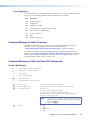
SIS Programming
and Control
This section describes SIS programming and control of the DMP 44 LC, including:
•
Connection Options
•
Command/Response Table for Basic SIS Commands
•
Special Characters
•
Command/Response Tables for DSP SIS Commands
Connection Options
The DMP 44 LC Digital Matrix Processor can be remotely connected via a host computer or
other device (such as a control system) attached to the rear panel RS‑232 port or the front
panel USB Config port.
The DMP 44 LC can be set up and controlled using the Extron SIS (Simple Instruction Set)
commands or DSP Configurator software. See the “Rear Panel Features and Cabling”
section for pin assignments and details on the configuration and control port connections.
For information on DSP Configurator see “Software Control.”
SIS commands may be executed using the Extron Electronics DataViewer program, which
may be found on the Software Products DVD included with the product.
DMP 44 LC RS-232 protocol:
•
38400 baud
•
no parity
•
8 data bits
•
no flow control
•
1 stop bit
NOTE: The rear panel configuration port supports 38400 baud communication. This
is a higher speed than that of many other Extron Electronics products. If using
HyperTerminal or a similar application, make sure the PC or control system
connected to these ports is set for 38400 baud.
See “RS-232 Port” for additional details on connecting the RS‑232 port.
USB port details:
The Extron USB driver must be installed before use (see “Install the USB Driver” for
driver installation instructions).
RS-232 Port
The DMP 44 LC has one serial port that can be connected to a host device such as a
computer running the HyperTerminal utility, DSP Configurator, or the DataViewer utility.
The port makes serial control of the DMP possible. Use the protocol information listed
above to make the connection. After the connection is made, see “Using the Command/
Response Tables” later in this section for SIS programming details.
DMP 44 LC • SIS Programming and Control
39
USB Port (front panel)
The DMP 44 LC has a front panel USB port that can be connected to a host device such as
a computer running the HyperTerminal utility, DSP Configurator, or the DataViewer utility.
The port makes serial control of the DMP possible. After the connection is established,
see “Using the Command/Response Tables” later in this section for SIS programming
details.
DMP 44 LC-initiated Messages
The DMP 44 LC initiates messages under specific conditions. No response is required from
the host. The DMP 44 LC-initiated messages are listed here (underlined).
© Copyright 2011, Extron Electronics, DMP 44 LC, Vn.nn, 60-1095-01
Vn.nn is the firmware version number.
The DMP 44 LC sends the boot and copyright messages under the following circumstance:
If the DMP 44 LC is off and an RS-232 connection is already set up (the PC is cabled to
the DMP 44 LC and a serial communication program such as HyperTerminal is open), the
connected unit sends these messages via RS-232 when first powered on.
Using the Command/Response Tables
SIS commands consist of a string (one or more characters per command field). No special
characters are required to begin or end a command sequence. When the DMP 44 LC
determines a command is valid, it executes the command and sends a response to the
host device. All responses end with a carriage return and a line feed (CR/LF = ]), signaling
the end of the response character string.
When programming, certain characters are more conveniently represented by their
hexadecimal rather than ASCII values. The following table shows the hexadecimal
equivalent of each ASCII character:
Space
ASCII to Hex Conversion Table
•
Figure 22.ASCII to Hex Conversion Table
DMP 44 LC • SIS Programming and Control
40
Error Responses
When the DMP 44 LC is unable to execute the command, it returns an error response to
the host. The error response codes and their descriptions are as follows:
Code
Description
E10
Invalid command
E11
Invalid preset
E12
Invalid port number
E13
Invalid parameter (number is out of range)
E14
Not valid for this configuration
E17
System timed out
E22
Busy
E25
Device is not present
Command/Response Table Overview
Although the DMP 44 LC uses the same structure for SIS commands, there are two
variations. One is the global command structure documented in the
“Command/Response Table for Basic SIS Commands” section that follows.
The second set of tables for DSP SIS commands uses the command structure outline
beginning with Command/Response Tables for DSP SIS Commands. While using the
same structure of basic SIS commands, they differ in how the software addresses the
individual processor blocks within the DMP 44 LC.
Command/Response Table for Basic SIS Commands
Symbol definitions
]
=
CR/LF (carriage return/line feed) (hex 0D 0A)
}
=
Carriage return (no line feed, hex 0D)
•
=
Space character
|
=
Pipe (vertical bar) character
E =
= =
X!
X@
X#
Escape key (hex 1B)
Future capability (not currently available)
=
Version number
Listed to two decimal places (for example, x.xx)
=
Version and Build number
Verbose/Response mode
The least significant bits is the build number (for example, x.xx.xxxx)
=
0 = clear or none
1 = verbose mode (not tagged, not broadcast)
2 = tagged responses for queries (tagged, not broadcast)
3 = verbose mode + tagged responses for queries (tagged and broadcast)
Default = 1 for RS-232 host control
NOTE:
X$
=
Baud rate
If ‘tagged responses’ is enabled, all read commands will return the
constant string + the data, like setting the value does, for example,
command: ECN}
response: Ipn•X1@]
0 = 9600
1 = 19200
2 = 38400 (default)
3 = 15200
DMP 44 LC • SIS Programming and Control
41
X%
X^
=
Internal temperature
Degrees Celsius
=
Dirty status
0 = RAM has been saved to Flash (OK to power off/reset)
1 = RAM needs to be saved to Flash
X&
=
Unit name
A text string of up to 24 characters drawn from the alphabet (A–Z) digits (0–9),
minus sign/hyphen (-). No blank or space characters are permitted as part of the
name. No distinction is made between upper and lower case. The first character
must be an alphabet character. The last character must not be a minus sign/
hyphen.
X*
X1)
X1@
X1#
X1$
X1%
X1^
X1&
X1*
=
Model name
=
Preset number
16 presets (1–16)
=
Inputs
Four inputs (1–4)
=
Outputs
Four outputs (1–4)
=
Group number
Sixteen groups (1–16)
=
Parameter number
6 = G, 12 = M
=
Soft limit High value
=
Soft limit Low value
=
Group master value
For gain values with a resolution to 0.1, multiply by 10.
Mute values: 0=Mute or 1 = unmute.
Special Characters
The HTML language reserves certain characters for specific functions. The device will not
accept these characters as part of preset names, the device name, or locally created file
names.
The DMP 44 LC rejects the following characters:
{space (spaces are acceptable for names)} + ~ ,
colon (:) | \ and ?.
@ = ‘ [
{ } < > ’ “
semicolon (;)
Command/Response Table for Basic DMP 44 LC SIS Commands
Command
NOTE:
ASCII Command
(Host to Tuner)
Response
(Tuner to Host)
Additional Description
Commands can be entered back-to-back in a string, with no spaces. Example: TvprS25*11•3
General commands
Firmware Version, Part Number, and Model Information
Query firmware version
Q
Query firmware and build
version
Query part number
Query model name
Query model description
*Q
N
1I
2I
X! ]
Show the current firmware
version.
Show the current firmware
X@ ]
and build version.
Show the unit part number.
60-1095-01 ]
Show the model name.
DMP•44•LC ]
Digital•Matrix•Processor ]
DMP 44 LC • SIS Programming and Control
42
Command
ASCII Command
Response
Additional Description
(Host to Tuner)
(Tuner to Host)
Set verbose mode
E X# CV }
Vrb X# ]
Set verbose/response mode.
0 = clear
1 = verbose
2 = tagged responses
3 = verbose + tagged
responses
View verbose mode
Set unit name
Set unit name to factory default
E CV }
E X& CN}
E • CN }
X# ]
Ipn • X& ]
Ipn • X* ]
View verbose mode
Set the unit name.
Set unit name to factory
default.
Ccp X$ ]
X$ = baud rate:
Setup Commands
Bidirectional Serial Data Port
Configure parameters
View parameters
E X$ CP }
E CP }
Ccp X$ ]
0 = 9600
1 = 19200
2 = 38400 (default)
3 = 15200
View baud rate.
ZAP Commands (Factory Defaults) and RAM Commands
Delete all presets and names
Delete individual preset
System reset (factory default)
E ZG }
E X1) ZG}
E ZXXX }
Zpg ]
Zpg X1) ]
Zpx ]
Absolute system reset
Commit only RAM to Flash
E ZQQQ }
E 2FF }
Zpq ]
Nvr X^ ] (responds when
done)
Query whether RAM needs to
be saved to Flash
E FF }
X^ ]
Write preset name
E X1) , name NG}
]
Nmg X1) , name Write preset name.
Read preset name
E X1) NG }
Read preset name.
Write input name
Read input name
E X1@ , name NI}
E X1@ NI}
Write output name
Read output name
E X1# , name NO}
E X1# NO }
Vrb mode 0/1:
name ]
Vrb mode 2/3:
]
Nmg X1) , name ]
Nmi X1@ , name Vrb mode 0/1:
name ]
Vrb mode 2/3:
]
Nmi X1@ , name ]
Nmo X1# , name Vrb mode 0/1:
name ]
Vrb mode 2/3:
]
Nmo X1# , name Delete all presets and names.
Delete specific preset.
Reset system to factory
default.
Similar to system reset.
X^ =
0 = RAM has been saved
1 = RAM has not been saved
Name commands
Write input name.
Read input name.
Write output name.
Read output name.
DMP 44 LC • SIS Programming and Control
43
Command
ASCII Command
(Host to Tuner)
Response
(Tuner to Host)
Additional Description
Partial preset commands
Recall preset
X1).
Rpr X1) ]
Recall preset.
Group Master Commands
Group Master Name
Set name
E n X1$* name GRPM }
GrpmN X1$*name ]
Set name
View name
E n X1$ GRPM }
name ]
View name
View name (verb mode 2/3)
E n X1$ GRPM }
GrpmN X1$*name ]
View name (verb mode 2/3)
E d X1$* + or – X1* GRPM
}
E d X1$* X1* GRPM }
E d X1$* X1* + GRPM }
E d X1$* X1* – GRPM }
E d X1$ GRPM }
GrpmD X1$ * X1* ]
Set + or –
]
GrpmD X1$*X1* ]
GrpmD X1$*X1* ]
GrpmD X1$*X1* Vrb mode 0/1: X1* ]
Vrb mode 2/3:
GrpmD X1$ * X1* ]
Set mute
Increment
Decrement
View master value.
View group members
E o X1$ GRPM }
View group members
View soft limits
E l X1$ GRPM }
Vrb mode 0/1:
<OID>*<OID>
...*<OID> ]
Vrb mode 2/3:
GrpmO
X1$*<OID>*<OID>
...*<OID> ]
Vrb mode 0/1:
X1^*X1& ]
Vrb mode 2/3:
]
GrmpL X1$*X1^*X1& Set Master Value
Set + or – dB
Set mute
Increment
Decrement
View master value
Set Group
View soft limits
DMP 44 LC • SIS Programming and Control
44
Digital Input Commands
Command
Configure digital input
View digital input
View I/O state
ASCII Command
Response
(Host to Tuner)
(Tuner to Host)
E X! * X@ * X# * X$ GPIT } GPIT X! * X@ * X# * X$ ]
E X! GPIT }
X@* X#* X$ ]
Vrb mode 2/3:
GPIT X! * X@* X#* X$ ]
X% ]
X!*]
Vrb mode 2/3:
Sio X! * X%
Additional Description
See table below
View digital input
View I/O state
Digital Input Command Table
X!
X@
=
Digital inputs 1–3
Inputs 1–3
=
Type of signal change to monitor for
0 = off (default)
1 = edge, hi to lo
2 = edge, lo to hi
3 = level lo
4 = level hi
X#
=
Function
0 = off (default)
1 = mute/unmute group
2 = increment group
3 = decrement group
4 = preset recall
X$
=
Preset or group number
preset range = 1–16
group range = 1–16
0 = off (default)
X%
=
State
0 = hi (voltage)
1 = lo (voltage)
DMP 44 LC • SIS Programming and Control
45
Command/Response Tables for DSP SIS Commands
Many digital signal processor (DSP) functions (gain, mute, and group masters) can be
controlled using SIS commands. These commands follow the same general rules as basic
SIS commands, but the variables (X/) tend to be more complex. Also, a comprehensive
understanding of the audio signal flow is helpful in understanding the commands.
The following figure shows the specific DSP processors available for SIS commands.
NOTE: The entire signal flow is described in more detail in the
“DSP Processing and Signal Flow”section.
d
a
b
e
c
Figure 23.DSP Processors Addressable via SIS Commands
The DSP Configurator program window consists of an input signal processor chain, the
mixer matrix, and an output signal processing chain. The following five processors can be
controlled using the DSP SIS commands:
a Line input gain control — Provides level adjustment, mute and polarity.
b Line input pre-mixer gain — Provides basic level adjustment after the input audio
processing chain and prior to the mix-point.
c Mix-points — Provide level adjustment and signal routing from the inputs to the
outputs.
d Output trim control — Provides level adjustment after the line input audio
processing.
e Output volume control — Provides volume control of the variable output, mute,
and polarity.
DMP 44 LC • SIS Programming and Control
46
Command/Response Tables for Audio SIS Commands
DSP control commands are an extension to SIS commands. They differ only in their data
string and the requirement to send each command with an “Au” suffix.
Symbol definitions
]
=
CR/LF (carriage return/line feed) (hex 0D 0A)
}
=
Carriage return (no line feed, hex 0D)
(use the pipe character, | , for Web browser commands))
•
=
Space character
|
=
Pipe (vertical bar) character
E =
Escape key (hex 1B) (use W instead of Esc for Web browsers)
NOTE: The dB values of the level settings are in 0.1 dB increments using negative numbers but not decimal
places. Multiply the desired level setting by ten for the SIS command value.
Example: To set an input level to 45.2 dB, use 452. To set an input level to -12.5 dB, use -125.
X6)
=
Gain and trim control or mix-point select
See “Table
X6!
=
Level value in dB;
dB value, in 0.1 dB increments using negative numbers but not decimal
places. The valid range depends on the type of gain block specified in the X6)
command: The valid range depends on the control or mix-point.
1. Level Control and Mix-point Selection Tables.”
a = –180 to 240 (–18 to +24 dB)
b = –1000 to 60 (–100 to +6.0 dB)
c = –240 to 120 (–24 to +12 dB)
d = –120 to 60 (–12 to +6.0 dB)
e = –1000 to 0 (–100 to 0.0 dB)
X6@
=
Input Polarity
0 = Standard
1 = Inverted
X6$
=
Mute status
0 = unmute
1 = mute
X6%
X6^
=
Group master group number
01 – 16
=
Group fader setting
dB value, in 0.1 dB increments using negative numbers but not decimal places.
The valid range depends on the type of gain block that is assigned to the group
number (X6%) specified in the command:
a = -180 to 800 (-18.0 dB to +80.0 dB)
b = -1000 to 120 (-100.0 dB to +12.0 dB)
c = -350 to 250 (-35.0 dB to + 25.0 dB)
d = -120 to 120 (-12.0 dB to +12.0 dB)
e = -1000 to 000 (-100.0 dB to +0.0 dB)
NOTE:
Leading zeros are ignored.
X6&
X6*
=
Group fader increment
dB value, in 0.1 dB increments, to raise or lower a group fader
=
Group fader soft limit
dB value, in 0.1 dB increments. The valid range X6^ must be within the range
for the gain block grouped in X6%.
X6(
=
Group type
6 = gain
12 = mute
X7)
=
Personal Identification Number (PIN)
Four numeric digits, default = 0000
DMP 44 LC • SIS Programming and Control
47
Special Characters
The HTML language reserves certain characters for specific functions. The device will not
accept these characters as part of preset names, the device name, passwords, or locally
created file names.
The DMP 44 LC rejects the following characters:
{space (spaces are acceptable for names)} + ~ ,
colon (:) | \ and ?.
@ = ‘ [ ] { } < > ’ “
semicolon (;)
Command/Response Table for DMP 44 LC DSP SIS commands
Command
ASCII Command
(Host to Tuner)
Response
(Tuner to Host)
Additional Description
Audio level control, and mix-point selection
NOTES: • The command format is the same regardless of the control or mix-point to be set; the acceptable
adjustment range varies depending on the control or mix-point. See X6! in the previous section.
• All responses are shown with the DMP 44 LC in Verbose mode 2 or 3.
Set a trim or gain (excluding
line inputs)
E G X6)*X6! AU}
DsGX6)*X6!]
Example 1 (pre-mixer
gain):
E G30003*– 8 AU}
DsG30003*– 8]
Example 2 (mix-point
gain):
E G20001*165AU}
DsG20001*165]
E G X6)*X6!AU}
DsGX6)*X6!]
E G30001*240AU}
DsG30001*240]
E G X6)AU}
DsGX6)*X6!]
Example 1
(post mixer trim control):
E G60101AU}
DsG60101*55]
Example 2 (mix control):
E G20203AU}
DsG20203*92]
E G X6)AU}
DsGX6)*X6@]
E G30000AU}
DsG30000*550]
Set a line gain
Example:
Read a trim or mix (excluding
line inputs)
Read a line gain
Example:
Set trim or mix control X6) to a
value of X6! dB.
Set pre-mixer 4 gain to a value of
-0.8 dB.
Mix +16.5 dB of line 1 into
output 2.
Set line gain control X6) to a
value of X6@ dB.
Set the mic/line input 2 gain to a
level of +24.0 dB.
DSP trim or mix control X6) is set
to a value of X6! dB.
Output 2, post mixer trim is set to
a value of +5.5 dB.
+9.2 dB of line 3 is mixed into
output 4.
Line gain control X6) is set to a
value of X6@ dB.
Line input 1 gain is set to a value
of +55.0 dB.
Audio mute
NOTES: • Post-mixer trim (d) cannot be muted.
• All responses are shown with the mixer device in Verbose mode 2 or 3.
Audio mute
Example:
Audio unmute
Read audio mute or level
E M X6)*1 AU}
E M20301*1AU}
E M X6)*0 AU}
E M X6)AU}
DsM X6)*1]
DsM20301*1]
DsM X6)*0 ]
DsM X6)*X6$ ]
Mute audio point X6).
Mute mix-point 4 to output 2.
Unmute audio point X6).
0 = mute off,
1 = mute on
DMP 44 LC • SIS Programming and Control
48
Command
ASCII Command
(Host to Tuner)
Response
(Tuner to Host)
Additional Description
Audio group master commands
NOTE:
See Group Masters, for more information about audio group masters.
A group must have assigned members for these commands to have an effect.
For X6^, a positive (+) value is assumed unless a negative (-) value is specified.
If entering a X6^ value outside the valid range for the group or outside the soft limits, the DMP 44
responds with an “invalid parameter” (E13) error.
• X6^, X6&, and X6* values can be sent without leading zeroes; responses are always 5 digits.
•
•
•
•
Set a group fader control
Example:
Raise a group fader control
E D X6%*X6^ GRPM}
Grpm X6%*X6^]
E D2*-293GRPM}
GrpmD02*00293GRPM]
Grpm X6%*X6^]
E D X6%*X6&+GRPM}
E D2*30+GRPM}
GrpmD02*00263*GRPM]
Lower a group fader control
E D X6%*X6&-GRPM}
Grpm X6%*X6^ ]
View the group fader control
level
Mute a group mute control
Clear (unmute) a group mute
control
View a group mute control
E D X6% GRPM}
Grpm X6%*X6^ ]
E D X6%*1GRPM}
E D X6%*0GRPM}
GrpmD X6%*+00001]
GrpmD X6%*+00000 ]
E D X6% GRPM}
GrpmD X6%*X6$ ]
Set soft limits
E L X6%*X6*upper*X6*lower
GRPM}
E L2*+60*-60GRPM}
GrpmL X6%*X6**X6* ]
View soft limits
E L X6% GRPM}
GrpmL X6%*X6**X6* ]
View group type
E P X6% GRPM}
GrpmP X6%*X6( ]
View group members
E O X6% GRPM}
GrpmOX6%*X6)1*X6)2*
...*X6)16 ]
Example
Example:
GrpmL2*+00060*
-00060 ]
Set the group fader to a value of
X6^.
Set the group 2 fader control to
-29.3 dB.
Increase the level of the X6%
group fader by X6& dB.
Raise the group 2 fader 3 dB
(from -29.3 dB to -26.3 dB,
starting from the level set in
the “Set a group fader control”
example, above.
Decrease the level of the X6%
group fader by X6& dB.
In verbose modes 1 and 2, the
response is simplified to X6^].
Mute all blocks in group X6%.
Umute all blocks in group X6%.
For group masters, X6$ is always
expressed as a positive or negative
5-digit value.
Set the groups soft limits to X6*
and X6*.
Set the upper soft limit for the
group 2 fader to +6.0 dB and the
lower limit to -6.0 dB.
In verbose modes 0 and 1,
the response is simplified to
X6**X6* ].
Show the group type (X6() for
group X6%. In verbose modes 0
and 1, the response is simplified
to X6( ].
X6) is the control or mix point.
In verbose modes 0 and 1,
the response is simplified to
X6)1*X6)2*...*X6)16].
DMP 44 LC • SIS Programming and Control
49
Table 1. Level Control and Mix-point Selection Tables
a Input Gain Control
X6)
b Pre-mixer Gain
X6)
Input 1
30000
Input 1
30100
Input 2
30001
Input 2
30101
Input 3
30002
Input 3
30102
Input 4
30003
Input 4
30103
c Main Mix-point
X6)
c Main Mix-point
X6)
Input 1 to Output 1
20000
Input 2 to Output 1
20100
Input 1 to Output 2
20001
Input 2 to Output 2
20101
Input 1 to Output 3
20002
Input 2 to Output 3
20102
Input 1 to Output 4
20003
Input 2 to Output 4
20103
c Main Mix-point
X6)
c Main Mix-point
X6)
Input 3 to Output 1
20200
Input 4 to Output 1
20300
Input 3 to Output 2
20201
Input 4 to Output 2
20301
Input 3 to Output 3
20202
Input 4 to Output 3
20302
Input 3 to Output 4
20203
Input 4 to Output 4
20303
d Post-mixer Trim
X6)
To Output 1
60100
To Output 2
60101
To Output 3
60102
To Output 4
60103
e Post-mixer Output
Volume
X6)
To Output 1
60000
To Output 2
60001
To Output 3
60002
To Output 4
60003
DMP 44 LC • SIS Programming and Control
50
Software Control
This section describes the control software for the DMP 44 LC, including:
•
Software Control
•
DSP Configurator Program
Software Control
The DMP 44 LC can be controlled using the DSP Configurator software, SIS commands
through HyperTerminal or DataViewer.
The DMP 44 LC has the following connection options:
•
RS-232 — One single stack 6-pole (shared with Digi In), 3.5 mm captive screw
connector is used for bi-directional RS-232 (±5 V) serial control.
See “Rear Panel Features and Cabling,” for additional details on connecting the
RS‑232 port.
•
USB 2.0 — A Mini B-type USB connector located on the front panel provides
high-speed USB 2.0 connectivity to a host computer, backward compatible to 1.0.
The DSP Configurator Control Program is compatible with Windows 2000,
Windows XP, Windows Vista®, and provides remote control of the input gain and
attenuation, output volume output adjustment, and other features.
DSP Configurator can control the DMP 44 LC via any of the two control ports, RS‑232 or
USB.
Updates to this program can be downloaded from the Extron website at
www.extron.com.
Installing the DSP Configurator Program
The program is contained on the Extron Software Products DVD.
Install the software as follows:
1. Insert the DVD into the drive
2. Click the Software tab or software icon.
NOTE: If the DVD setup program does not start automatically, run Launch.exe
from the DVD ROM directory in “My Computer” of the Windows
operating system.
DMP 44 LC • Software Control
51
Figure 24. DVD Software Menu
3. Scroll to the DSP Configurator program and click the Install text to its right, as
shown in the red boxes below.
Figure 25. DVD Control Software Menu
4. Follow the on-screen instructions. By default, the Windows installation creates
a DSP_Configurator folder in C:\Program Files\Extron for the DSP Configurator
program files.
5. When the DSP Configurator installation is complete, the USB Installer starts
automatically. It is recommended to install the USB drivers whether they are used
immediately or not.
DMP 44 LC • Software Control
52
Install the USB Driver
To install the USB driver, follow these instructions.
Figure 26.USB Installer Splash Screen
1. After the DSP Configurator program installation is complete, click Next to proceed.
Figure 27. USB Installation
DMP 44 LC • Software Control
53
2. The USB driver installer launches. When the installer has completed the installation of
the USB drivers, the following screen appears:
Figure 28. Successful USB Driver Installation
3. Click Finish.
USB driver installation is complete.
DSP Configurator Program
Starting the Program
1. To run the DSP Configurator Program, click
Start > Programs > Extron Electronics > DSP Configurator
> DSP Configurator.
The DSP Configurator program starts in Emulate mode (see “Emulate Mode vs.
Live Mode”).
DMP 44 LC • Software Control
54
2. Select the device to be configured and then click OK.
3. The program displays the following screen.
Using the Program
In Emulate mode, audio parameters may be selected, then transferred to the DMP 44 LC
by going to Live mode (while connected to a DMP 44 LC). See the following section.
Audio settings can also be tailored while connected to the DMP 44 LC, allowing real-time
auditioning of the audio output as adjustments are made.
DMP 44 LC • Software Control
55
Emulate Mode vs. Live Mode
The DSP Configurator program has two operational modes, Live and Emulate. In Live mode,
the program has established a connection and is synced with the DMP 44 LC. Changes
affect the device in real-time and changes in the current state of the device are reflected
in DSP Configurator. Emulate mode allows the user to work offline, creating or editing
configurations that do not affect DMP 44 LC operation until they are uploaded to the
device.
The DSP Configurator program always starts in Emulate mode. In Emulate mode, the
program provides access to all functions of the DMP 44 LC without connecting to it.
The user can build a configuration from the default screen, or open an existing file
that contains a previously saved configuration. Settings and adjustments are saved to a
configuration file on the PC. In Emulate mode when a previously saved file is opened, it
becomes the current emulation in the Presets window. A new or previous file cannot be
opened in Live mode.
Figure 29.Main DSP Configuration Screen at Startup
The user can enter Live mode at any time after program launch, either with a blank
configuration, after creating a configuration, or after loading a previously saved
configuration file.
Synchronizing: Pull vs. Push
When switching to Live mode after making changes to the current configuration in
emulate mode, either:
•
Pull data from the device and update the DSP Configurator program configuration.
This option downloads device settings from the DMP 44 LC and synchronizes it with
the DSP Configurator program overwriting the current DSP Configurator settings, or
•
Push data from the DSP Configurator program to the device, overwriting settings in
the DMP 44 LC.
Live mode can also be used to tailor audio settings in real‑time while listening to the audio
output.
DMP 44 LC • Software Control
56
Selecting Live Mode and Pushing or Pulling a Configuration
To switch from emulate mode to live mode:
4. Click the Live button, see a on the main DSP Configurator screen. The
Connect to device... dialog box opens.
1
2a
2b
3a
3b
- or -
DMP 44LC
4a
3c
4b
Figure 30. Selecting Live Mode
5. As needed, click either the:
a. RS-232 tab (for connection to the rear panel RS-232 ports — proceed to step 3,
b. USB tab (for connection via the front panel configuration port — proceed to
step 4.
6. If RS-232 was selected in step 2:
a. Click the Com Port drop-down menu and select the PC com port connected to
the rear panel RS-232 port.
b. Check the baud rate displayed in the Baud Rate field. If the baud rate does not
match the device rate, click the Baud Rate drop-down menu and select the
desired baud rate. The default is 38400.
c. Click OK.
The Synchronize with Device dialog box appears. Proceed to step 5.
7. If USB was selected in step 2:
a. Click the USB Device drop-down menu and select DMP 44 LC (or
Extron USB device, if DMP 44 LC is not available),
b. Click OK.
The Synchronize with Device dialog box appears. Proceed to step 5.
Several options are now available for either configuring the DMP 44 LC or
reconfiguring to suit current operating conditions.
DMP 44 LC • Software Control
57
8. Click either the:
a. Pull radio button to overwrite the open file with the current device
configuration, thenproceed to step 6.
-orb. Push radio button to overwrite the open file, then proceed to step 6.
8a
-or8b
9
9
10
11
Figure 31. Selecting Live Mode, continued
DMP 44 LC • Software Control
58
9. Click OK. The DSP Configurator program is connected live to the device and the
configuration and presets are pushed or pulled as selected.
•
If Pull is selected, the program overwrites the currently open file with the
configuration from the device. Proceed to step 7.
•
If Push is selected, the program overwrites the device configuration with the
currently open file. Proceed to step 7.
NOTE: In either case, the program and device configuration now reflects
DSP Configurator changes in real-time.
If the file has been previously saved and has not changed, step 7 is
skipped.
10.If changes have been made to the DSP parameters (including mix-point, gain or
processor blocks) since the last file save, DSP Configurator prompts to save the file.
Click Yes or No, as necessary,
a. Click Yes to save the currently open configuration to an existing file or to create a
new one, then proceed to step 8.
b. Click No to push the currently open configuration to the DMP 44 LC. After the
configuration is complete, DSP Configurator remains connected to the DMP 44 LC
in Live mode.
11.Either enter a new file name, or select an existing file from the list then click Save.
The DSP Configurator program uploads the current file to the DMP 44 LC. The file
overwrites the configuration of the device, and DSP Configurator is now connected
live. Further changes to the configuration will be reflected immediately in the device
operation.
Presets
Presets are used to recall a group of frequently used settings. Presets created by
DSP Configurator may contain all elements (gain blocks, processor blocks, and mix-points)
or a portion of the elements available within the program. In Emulate mode, up to 16
presets can be created, then uploaded as a set and stored to the device or stored to disk
as a configuration file. In Live mode, presets can be created one at a time from the current
state. They can then be saved to a chosen preset number in the device, with the option to
name, rename or save to disk.
When recalled, a preset only overwrites elements contained in the preset. Presets are
useful when settings for a particular room or only certain elements of a configuration need
to be changed regularly.
An additional preset contains current state information if reading from the device in Live
mode, or the state of DSP Configurator if in Emulate mode (titled current emulation).
Current emulation can be a configuration not yet saved as a preset (work in progress), the
last preset or combination of presets recalled within DSP Configurator, or the current state
of the device as a result of switching from Live to Emulate mode.
Presets may be created in Live or Emulate modes. In Emulate mode, the preset or presets
are created, saved to a file, then pushed to the DMP 44 LC when connecting in Live mode.
When a Pull data synchronization is performed, preset data remains in the DMP 44 LC,
with only the list of preset names pulled from the device. Presets in this state are marked
with an asterisk until that preset is recalled (which pulls the preset data from the device),
or until a backup is performed. Presets pulled from the device cannot be saved to disk until
they have been recalled, at which time the preset data is pulled into DSP Configurator.
Presets with no asterisk can be saved to disk.
DMP 44 LC • Software Control
59
Saved presets can be recalled via the DSP Configurator, or a control system sending an
SIS preset recall command. Presets may also be saved and recalled via the embedded web
page. Presets saved via the web page contain input gain, output volume, and the primary
mix-point settings.
Previewing/Recalling a Preset
A preset can be previewed in either Live or Emulate mode by selecting the preset from the
presets drop-down list.
Figure 32.Preset Preview
The program indicates a view-only preset configuration by displaying each preset element
with a translucent green mask over the block. In the example, the input processors are
included in Preset 1 - Input Procs.
Behavior for previewing and applying presets is as follows:
•
Live Mode — After selecting a preset, DSP Configurator displays the preset elements
that will be affected by a preset recall with a translucent mask over the element, and
leaves all other DSP Configurator elements unaltered. Elements without a translucent
mask represent elements in the current state that will be unaffected by a preset
recall. Real-time changes to the current state will not be reflected in the GUI while
previewing a preset, and the user cannot alter GUI elements. To apply the preset, the
user clicks Recall. The preset reverts to “Current State.”
•
Emulate Mode — After selecting a preset from the list, DSP Configurator displays the
elements that will be affected by a preset recall with a green translucent mask, leaving
all other elements (which represent the current emulation) unaltered. The user clicks
Recall to apply the viewed preset to the current emulation. The preset number
reverts to “Current Emulation.”
DMP 44 LC • Software Control
60
Building a Preset
Only elements that are highlighted (given focus) will be saved as a preset. <Ctrl + A>
highlights all elements within DSP Configurator.
To build a preset, highlight the desired DSP Configurator elements (gain/processor blocks,
mix-points) using standard Windows keyboard and mouse actions as follows:
1. <Left click> on the desired block to select a single block,
2. <Ctrl + left click> to select multiple blocks that are not adjacent,
3. <Shift/hold + click> on the first block and click on the last block in either a vertical
column or horizontal row to select multiple blocks, and
4. Click and drag a selection rectangle to select multiple adjacent blocks in either the
vertical or horizontal direction.
5. Go to Tools > Presets and select Mark All Items or press <Ctrl + A>. This
marks all elements within DSP Configurator, which saves a “full” preset,
6. To save the selection see “Save Preset” below.
Save Preset
A preset may be saved in either Emulate mode or Live mode.
Saving a preset in Emulate mode stores that preset in the currently open file. The
DSP Configurator file must then be saved to disk via File > Save (recommended),
and/or pushed to the device after a connection is established. This differs from Live mode
where the created preset is saved in real‑time to the device and becomes part of the
configuration file.
To save a preset use the following instructions:
1. Highlight the desired preset block by using left click, <Ctrl + left click>,
<shift + left click> or drag around the desired blocks.
2. Select Tools > Presets > Save Preset in the menu bar.
DMP 44 LC • Software Control
61
3. Select a preset number. In the Preset Name field, unused presets are named
“unassigned.” To create a new preset, select an unused preset number and type a
preset name. If no name is entered, a default name will be assigned. To overwrite an
existing preset, select a preset with a name other than “unassigned.”
Figure 33. Save Preset
4. Click OK to save the preset, or Cancel to stop the save preset operation.
Managing Presets in the GUI
After the preset is created (whether or not the DSP Configurator file is saved), it appears in
the preset list, available from the presets bar.
In Live and Emulate mode, after a preset is selected from the list, action buttons become
available next to the presets bar.
The user can either Recall (make the preset active), Cancel (return to the current emulation
or state) or Delete the preset.
In Live mode selecting Recall first applies the currently displayed preset elements
(“marked” elements) from the stored preset and overwrites that portion of the current
state, then switches the drop-down list to read “Current State.”
In Emulate mode, the Recall action button applies the currently displayed preset
elements (“marked” elements) from the file and overwrites the information contained
in DSP Configurator as the current emulation, then switches the drop‑down list to read
“Current Emulation.”
DMP 44 LC • Software Control
62
When a preset is being previewed, in either Live or Emulate mode, the Delete button
is available. In Live mode, the preset is deleted from the hardware, which is reflected in
software (it is removed from the preset list). After disconnecting from the device and
before exiting the program, the file must then be saved to retain this change. In Emulate
mode, the preset is deleted from the file in software, which must then be saved (before
exiting) to retain this change. In either Live or Emulate mode, the Cancel button
defeats the preview action and returns the user to the current state or current emulation,
respectively.
Presets: Pull vs. Push or Create Live
When a preset is pulled from the device, the preset data remains in the device until the
preset has been recalled. DSP Configurator pulls only the names of the presets. These
presets cannot be saved to disk until they have been recalled.
An asterisk next to the preset name indicates that only the preset name has been pulled
from the device, and the preset data only exists in the device (it has not been recalled).
Presets pushed to the device or created in DSP Configurator while in Live mode have no
asterisk. Presets with no asterisk can be saved to disk.
DMP 44 LC • Software Control
63
Push Configuration - Advanced,
Push Presets, All
There are a number of advanced
options available when pushing
a configuration that enable the
user to tailor the input, signal
processing, signal mix, or output
to a specific preset operation.
This allows the user to push the
currently open configuration,
including all presets, to the
DMP 44 LC or to customize
the push to include either the
configuration, selected presets,
or both.
To use the advanced push
feature:
Connect the DMP 44 LC as
described by steps 1 to 4 in the
previous procedure for switching
from Emulate mode to Live mode
(see “To switch from emulate
mode to live mode:”), then:
1. Select the Push radio
button, then click
Advanced.
1
1
2a
2b
3a
3b
4
NOTE:Clicking OK at this
time pushes the
currently open
configuration to the
DMP 44 LC.
2. The program asks you to
choose an option:
a. Choose
Default to update the
device configuration
with the currently open
file. Proceed to step 4.
5
b. Choose Custom
for additional
options. Proceed to
step 3.
NOTE: In either case, the
program and device
configuration now
reflect DSP Configurator
changes to the DMP 44 LC
configuration in real-time.
6
DMP 44 LC • Software Control
64
3. There are three options now available; Push Configuration, Push Presets or
both. In this example, Push Configuration is not selected and all presets will be
pushed.
a. Select Push Presets only. This enables two additional options, All and
Selected.
b. Select All. Push Presets-All uploads all stored presets from DMP Configurator to
the device overwriting previous presets.
4. Click OK. The Synchronize with Device dialog box appears.
5. Leave all selections as they are and click OK again to push the presets to the device.
6. If changes have been made to the DSP parameters (including mix-point, gain or
processor blocks) since the last file save, DSP Configurator prompts to save the file.
Click Yes or No, as necessary,
a. Click Yes to save the currently open configuration to an existing file or to create a
new one. The new configuration is pushed to the device.
b. Click No to ignore the file changes. The currently open configuration is pushed to
the DMP 44 LC.
DMP 44 LC • Software Control
65
Push Configuration - Advanced, Push Presets, Selected
The next example shows how to customize a
push to include only selected presets.
Connect the DMP 44 LC as described by steps
1 to 4 in the previous procedure for switching
from Emulate mode to Live mode (see
“To switch from emulate mode to live mode:”),
then:
1
1
1. Select the Push radio button, then click
Advanced.
NOTE:Pressing OK at this time pushes
the currently open configuration
to the DMP 44 LC.
2. Select the Custom radio button.
3. Select Push Presets.
2
3
4. Choose Selected.
5. Click OK. The Synchronize with Device
dialog box appears.
4
6. If it is not selected, select the Push the
data... radio button and click OK again.
5
7. If changes have been made to the DSP
parameters (including mix-point, gain or
processor blocks) since the last file save, the
DSP Configurator prompts to save the file.
a. Click Yes to open the file selection box,
see previous sections for the Save File
as... dialog box instructions. Accept
the name, choose an existing file name
or create a new one and click OK. The
new configuration is pushed to the device.
6
b. Click No to ignore the changes.
8. The Presets in the Configuration dialog
box opens. Select the preset configurations
to push to the DMP 44 LC. A
checkmark appears for each selection.
In this example, a checkmark has been placed
in the 1. Input Procs and
4. Output XPA preset check boxes.
9. Press OK. The DSP Configurator program
saves the configuration then updates the
DMP 44 LC configuration, overwriting the
configuration in the device. When the
transmit and receive indicators stop flashing,
the upload is complete and the DSP Configurator program is now connected
live to the DMP 44 LC.
7b
7a
8
Changes to the configuration are reflected
immediately in the device operation.
9
DMP 44 LC • Software Control
66
Reference
Information
This section contains reference information for the DMP 44 LC, including:
•
Specifications
•
Part Numbers and Accessories
•
Mounting
•
Firmware Loader
•
DMP 44 LC Hardware Reset Modes
Specifications
Audio
Gain����������������������������������������������� Unbalanced output: -6 dB; balanced output: 0 dB
Frequency response������������������������ 20 Hz to 20 kHz, ±0.3 dB
THD + Noise����������������������������������� <0.02% @ 1 kHz, at maximum output level
S/N������������������������������������������������� >100 dB, 20 Hz to 20 kHz, at maximum output, unweighted
Crosstalk���������������������������������������� <-90 dB @ 1 kHz, fully loaded
CMRR�������������������������������������������� >60 dB @ 1 kHz
Audio input
Number/signal type������������������������ 4 mono, line, balanced/unbalanced
Connector�������������������������������������� (2) 3.5 mm captive screw connectors, 6 pole
Impedance������������������������������������� >10k ohms unbalanced/balanced
Nominal level��������������������������������� +4 dBu when level is set to 0 dB gain; adjustable from -20
dBu to +4 dBu
Maximum level������������������������������� +21 dBu, balanced, when input gain is set to 0 dB
Volume range��������������������������������� -18 dB to +24 dB, line input, adjustable per input
NOTE: 0 dBu = 0.775 Vrms, 0 dBV = 1 Vrms, 0 dBV ≈ 2 dBu
Audio processing
D/A conversion������������������������������� 24 bit, 48 kHz sampling
Audio output
Number/signal type������������������������ 4 mono, line, balanced/unbalanced
Connectors������������������������������������ (2) 3.5 mm captive screw connectors, 6 pole
Impedance������������������������������������� 50 ohms unbalanced, 100 ohms balanced
Gain error�������������������������������������� ±0.2 dB channel to channel
Maximum level (Hi-Z)���������������������� >+21 dBu balanced, >+15 dBu unbalanced
DMP 44 LC • Reference Information
67
Control/remote — audio processor
Serial host control port������������������� 1 bidirectional RS-232: 3.5 mm captive screw connector, 6
pole (uses 3 poles) (shared with digital input)
Baud rate and protocol������������������� 9600 to 115200 baud (38400 baud = default), 8 data bits, 1
stop bit, no parity, no flow control
Serial control pin configuration������� Pin 1 = Tx, 2 = Rx, 3 = GND
USB control ports��������������������������� 1 front panel female mini USB B
USB standards�������������������������������� USB 2.0, low speed
Program control����������������������������� Extron control/configuration program for Windows®
Extron Simple Instruction Set (SIS™)
Control — digital input ports
Number/type���������������������������������� 3 digital input (configurable)
Connector�������������������������������������� (1) 3.5 mm captive screw connector, 6 pole (shared with
RS-232 port, uses 4 poles)
Pin configuration���������������������������� 3 = GND; 4, 5, 6 = digital inputs 1, 2, 3
Digital inputs
Input voltage range����������������� 0-24 VDC
Input impedance���������������������� 10k ohms
Threshold low to high�������������� >2.0 VDC
Threshold high to low�������������� <0.8 VDC
General
Power�������������������������������������������� External
Input: 100-240 VAC, 50-60 Hz
Output: 12 VDC, 1 A
Power consumption����������������������� 3.6 watts
Temperature/humidity�������������������� Storage: -40 to +158 °F (-40 to +70 °C) / 10% to 90%,
noncondensing
Operating: +32 to +122 °F (0 to +50 °C) / 10% to 90%,
noncondensing
Cooling������������������������������������������ Convection, no vents
Mounting
Rack mount����������������������������� Yes, with optional 1U rack shelf
Furniture mount���������������������� Yes, with optional under-desk mounting kit
Enclosure type�������������������������������� Metal
Enclosure dimensions��������������������� 1.7" H x 4.3" W x 3.0" D (1U high, quarter rack wide)
(4.3 cm H x 10.9 cm W x 7.6 cm D)
(Depth excludes connectors.)
Product weight������������������������������� 0.6 lbs (0.3 kg)
Shipping weight����������������������������� 3 lbs (2 kg)
Vibration���������������������������������������� ISTA 1A in carton (International Safe Transit Association)
Regulatory compliance
Safety�������������������������������������� CE, c-UL, UL
EMI/EMC��������������������������������� CE, C-tick, FCC Class A, ICES, VCCI
Environmental�������������������������� Complies with the appropriate requirements of RoHS, WEEE
MTBF��������������������������������������������� 30,000 hours
Warranty���������������������������������������� 3 years parts and labor
NOTE: All nominal levels are at ±10%.
NOTE: Specifications are subject to change without notice.
8.0-083111-D4
DMP 44 LC • Reference Information
68
Part Numbers and Accessories
Included Parts
These items are included in each DMP 44 LC order:
Included parts
Replacement part
number
DMP 44 LC Digital Matrix Processor
60-1095-01
3.5 mm, 5-pole captive screw connectors w/strain
relief (5)
10-703-12LF
12 VDC, 1 A external power supply
70-775-01
DSP Configurator Control Software DVD
Rubber Feet (4)
Nylon tie wraps (5)
Tweeker
DMP 44 LC Setup Guide
Accessories
These items can be ordered separately:
Adapters, power supplies, labels
Part number
USB A Male to USB Mini B Male Configuration Cable
26-654-06
MBU 123, Under-Desk Mount Kit
70-212-01
RSB 126, Basic Rack Shelf Kit for 6" deep products
60-604-11
RSU 126, Universal Rack Shelf Kit for 6" deep products
60-190-10
Mounting
The 1U high, quarter rack width, 3-inch deep DMP 44 LC Digital Matrix Processor can be:
•
Set on a table,
•
Mounted on a rack shelf,
•
Mounted under a desk or tabletop, or
•
Mounted on a projector bracket.
Tabletop Use
Each DMP 44 LC comes with rubber feet (not installed). For tabletop use, attach a
self‑adhesive rubber foot to each corner of the bottom of the unit.
DMP 44 LC • Reference Information
69
UL Rack Mounting Guidelines
The following Underwriters Laboratories (UL) guidelines pertain to the safe installation of
the DMP 44 LC in a rack.
1. Elevated operating ambient temperature — If installed in a closed or multi-unit
rack assembly, the operating ambient temperature of the rack environment may be
greater than room ambient temperature. Therefore, install the unit in an environment
compatible with the maximum ambient temperature (Tma = +122 °F, +50 °C)
specified by Extron.
2. Reduced air flow — Install the equipment in a rack so that the amount of air flow
required for safe operation of the equipment is not compromised.
3. Mechanical loading — Mount the equipment in the rack so that a hazardous
condition is not achieved due to uneven mechanical loading.
4. Circuit overloading — Connect the equipment to the supply circuit and consider the
effect that circuit overloading might have on overcurrent protection and supply wiring.
Appropriate consideration of equipment nameplate ratings should be used when
addressing this concern.
5. Reliable earthing (grounding) — Maintain reliable grounding of rack-mounted
equipment. Pay particular attention to supply connections other than direct
connections to the branch circuit (such as the use of power strips).
Rack Mounting
For optional rack mounting, do not install the rubber feet. Mount the DMP 44 LC on
a 19” Universal 1U or Basic rack shelf (Extron RSU 126, part number 60-190-10; or
Extron RSB 126, part number 60-604-11).
To rack mount the DMP 44 LC:
1. If rubber feet were previously installed on the bottom of the DMP 44 LC, remove
QuarterRackStandardShelf
them.
2. Mount the DMP 44 LC on the rack shelf, using two 4-40 x 3/16 inch screws in
opposite (diagonal) corners to secure the unit to the shelf.
1U Universal Rack Shelf
1/2 Rack Width Front False
Faceplate
1/4 Rack Width Front False
Faceplate
Both front false faceplates
use 2 screws.
Use 2 mounting holes on
opposite corners.
(2) 4-40 x 3/16"
Screws
Figure 34. Mounting the DMP 44 LC on a Universal Rack Shelf
DMP 44 LC • Reference Information
70
3. Install blank panels or other units on the rack shelf.
Furniture Mounting
Furniture mount the DMP 44 LC using the optional mounting kit (Extron MBU 123, part
number 70-212-01, as follows:
1. Attach the selected mounting brackets with the machine screws provided.
2. If feet were previously installed on the bottom of the cabinet, remove them.
3. Hold the unit with the attached brackets against the underside of the table or other
furniture, or against the wall. Mark the location of the screw holes of the bracket on
the mounting surface.
4. Drill 3/32 inch (2 mm) diameter pilot holes, 1/4 inch (6.4 mm) deep in the mounting
surface at the marked screw locations.
5. Insert #8 wood screws into the four pilot holes. Tighten each screw into the mounting
surface untilQuarterRackUnderdeskMounting
just less than 1/4 inch of the head of the screw protrudes.
6. Align the mounting screws with the slots in the brackets and place the unit against
the surface, with the screws through the bracket slots.
7. Slide the unit slightly forward or back, then tighten all four screws to secure it in
place.
Figure 35. MBU 123, Under-Desk Mounting
DMP 44 LC • Reference Information
71
Firmware Loader
The DSP Configurator program includes a firmware loader program which allows replacing
the firmware without taking the DMP 44 LC out of service. Download the desired
firmware file from the Extron website, (see the Firmware Upgrade Page on the website for
instructions).
To access the firmware loader:
1. Select Tools, then Firmware Loader.
2. The Add Device dialog box appears. Type the IP address of the DMP 44 LC, then click
OK.
NOTE: If the IP has not been changed, the default IP address is:
192.168.255.255.
DMP 44 LC • Reference Information
72
The Firmware Loader screen appears.
3. From the toolbar, select File > Open.
4. Locate the downloaded firmware file and click on it.
5. Click Begin on the main screen. The total progress bar tracks the loading progress.
6. When the upload is finished, exit the program by selecting File > Exit.
The firmware upload is complete.
DMP 44 LC • Reference Information
73
DMP 44 LC Hardware Reset Modes
DMP 44 LC Reset Mode Summary
Mode Mode Activation
1
Use Factory Firmware
NOTE: After a mode 1 reset,
update the DMP 44 LC
firmware to the latest
version. DO NOT
operate the firmware
version that results from
this mode reset.
5
Reset to
Factory Defaults
Hold the reset button while
applying power.
Press and hold the Reset button for
about 9 sec. until the Power LED
blinks three times (once at 3 sec.,
again at 6 sec., again at 9 sec.),
then release and within 1 second
press Reset momentarily (< 1 sec.).
NOTE: The reset procedure is
aborted if the second
momentary press does
not occur within one
second.
Result
Purpose/Notes
The DMP 44 LC reverts to the
factory default firmware.
Event scripting does not start if the
DMP 44 LC is powered on in this
mode. All user files and settings
(drivers, adjustments, IP settings,
etc.) are maintained.
This mode reverts to the
factory default firmware
version if incompatibilty
issues arise with userloaded firmware.
NOTE: If you do not want to
update the firmware, or
perform a mode 1 reset
by mistake, cycle power
to the DMP 44 LC to
return to the firmware
version running prior to
the reset.
Mode 5 performs a complete
reset to factory defaults, except
for firmware:
• Does everything mode 4 reset
does.
• All mix-points set muted and
set to 0 dB.
• All outputs unmuted and set to
0 dB.
• DSP processing returned to
defaults and bypassed.
• All inputs muted and set to
0 dB.
• All presets and group master
memory cleared.
NOTE: User-defined
Web pages
may not work
correctly
if using
an earlier
firmware
version.
Useful to start over
with configuration
or uploading, and to
replace events.
DMP 44 LC • Reference Information
74
Extron Warranty
Extron Electronics warrants this product against defects in materials and workmanship for a period of three years
from the date of purchase. In the event of malfunction during the warranty period attributable directly to faulty
workmanship and/or materials, Extron Electronics will, at its option, repair or replace said products or components,
to whatever extent it shall deem necessary to restore said product to proper operating condition, provided that it is
returned within the warranty period, with proof of purchase and description of malfunction to:
USA, Canada, South America,
and Central America:
Extron Electronics
1001 East Ball Road
Anaheim, CA 92805
U.S.A.
Japan:
Extron Electronics, Japan
Kyodo Building, 16 Ichibancho
Chiyoda-ku, Tokyo 102-0082
Japan
Europe, Africa, and the Middle
East:
Extron Europe
Hanzeboulevard 10
3825 PH Amersfoort
The Netherlands
China:
Extron China
686 Ronghua Road
Songjiang District
Shanghai 201611
China
Asia:
Extron Asia
135 Joo Seng Road, #04-01
PM Industrial Bldg.
Singapore 368363
Singapore
Middle East:
Extron Middle East
Dubai Airport Free Zone
F12, PO Box 293666
United Arab Emirates, Dubai
This Limited Warranty does not apply if the fault has been caused by misuse, improper handling care, electrical or
mechanical abuse, abnormal operating conditions, or if modifications were made to the product that were not
authorized by Extron.
NOTE: If a product is defective, please call Extron and ask for an Application Engineer to receive an RA (Return
Authorization) number. This will begin the repair process.
USA: 714.491.1500 Asia: +65.6383.4400
Europe: +31.33.453.4040
Japan: +81.3.3511.7655
Units must be returned insured, with shipping charges prepaid. If not insured, you assume the risk of loss or damage
during shipment. Returned units must include the serial number and a description of the problem, as well as the
name of the person to contact in case there are any questions.
Extron Electronics makes no further warranties either expressed or implied with respect to the product and its quality,
performance, merchantability, or fitness for any particular use. In no event will Extron Electronics be liable for direct,
indirect, or consequential damages resulting from any defect in this product even if Extron Electronics has been
advised of such damage.
Please note that laws vary from state to state and country to country, and that some provisions of this warranty may
not apply to you.
Extron Headquarters
+1.800.633.9876 (Inside USA/Canada Only)
Extron USA - West
Extron USA - East
+1.714.491.1500+1.919.850.1000
+1.714.491.1517 FAX
+1.919.850.1001 FAX
Extron Europe
+800.3987.6673
(Inside Europe Only)
+31.33.453.4040
+31.33.453.4050 FAX
Extron Asia
+800.7339.8766
(Inside Asia Only)
+65.6383.4400
+65.6383.4664 FAX
Extron Japan
+81.3.3511.7655
+81.3.3511.7656 FAX
© 2012 Extron Electronics All rights reserved.
Extron China
+4000.398766
Inside China Only
+86.21.3760.1568
+86.21.3760.1566 FAX
Extron Middle East
+971.4.2991800
+971.4.2991880 FAX
www.extron.com
Extron Korea
+82.2.3444.1571
+82.2.3444.1575 FAX
Extron India
1800.3070.3777
Inside India Only
+91.80.3055.3777
+91.80.3055.3737 FAX