1
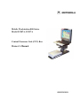
Mobile Workstation 800 Series
Model F5207A, F5217A
Central Processor Unit (CPU) Box
Owner’s Manual
6802976C60-O
2
MW800 CPU Owner’s Manual
COMPUTER SOFTWARE COPYRIGHTS
The Motorola products described in this instruction manual may include copyrighted
Motorola computer programs stored in semiconductor memories or other media. Laws in
the United States and other countries preserve for Motorola certain exclusive rights for
copyrighted computer programs, including the exclusive right to copy or reproduce in
any form the copyrighted computer program. Accordingly, any copyrighted Motorola
computer programs contained in the Motorola products described in this instruction
manual may not be copied or reproduced in any manner without the express written
permission of Motorola. Furthermore, the purchase of Motorola products shall not be
deemed to grant either directly or by implication, estoppel or otherwise, any license under
the copyrights, patents or patent applications of Motorola, except for the normal nonexclusive, royalty free license to use that arises by operation of law in the sale of a
product.
COPYRIGHT
Copyright © 2003-2004 Motorola Inc. All rights reserved. No part of this manual may be
transmitted, stored in a retrieval system, or translated into any language or computer
language, in any form or by any means, without the prior written permission of Motorola
Inc.
TRADEMARKS
• Motorola and the Stylized M logo, Private DataTAC, iDEN are registered trademarks
of Motorola Inc.
• Microsoft, Windows and the Windows logo are registered trademarks of Microsoft
Corporation.
• Intel, Pentium are registered trademarks of Intel Corporation.
• The Bluetooth trademarks are owned by their proprietor and used by Motorola, Inc.
under license in the U.S. and other countries.
• Trimble is a registered trademark of Trimble Navigation Limited
• u-Blox is a registered trademark of u-Blox AG.
• Phoenix, WinPhlash are registered trademarks of Phoenix Technology Limited.
All other product or service names are the property of their respective owners.
WARRANTY DISCLAIMER
Motorola may add, delete, change, or withdraw, in whole or in part, this document or
software described in this document at any time and without notice. Such document
modifications will be incorporated in new releases of this document on an intermittent
basis. Motorola disclaims any responsibility for labor or material cost involved by
persons outside the company as a result of using this document.
3
TABLE OF CONTENTS
Using this Manual .......................................................................................................................................... 5
Who Should Use this Manual .................................................................................................................... 5
Manual Introduction .................................................................................................................................. 5
Related Manuals ........................................................................................................................................ 6
Conventions Used in This Manual............................................................................................................. 6
Section 1:
Getting Started ................................................................................................................... 8
What is the CPU Box?............................................................................................................................... 8
Section 2:
Basic Operations ................................................................................................................ 9
Power On ................................................................................................................................................... 9
Normal operation .................................................................................................................................. 9
Low Temperature Conditions ..............................................................................................................10
High Temperature Conditions..............................................................................................................10
Discharged Vehicle Battery .................................................................................................................10
Shut Down ................................................................................................................................................10
Normal Operation ................................................................................................................................11
Extreme Shut Down.............................................................................................................................11
Power Management ..................................................................................................................................12
Standby ................................................................................................................................................12
Resume ................................................................................................................................................13
Resetting ...................................................................................................................................................13
Section 3:
CPU Configuration ...........................................................................................................15
CPU Configuration Parameters ................................................................................................................15
BIOS Setup ...............................................................................................................................................18
CPU Configuration Change ......................................................................................................................18
Maintenance Programming Software...................................................................................................18
How to Modify Configuration Parameters...........................................................................................18
Section 4:
CPU Software ...................................................................................................................20
CPU Manager ...........................................................................................................................................20
MW800 Display Utilities..........................................................................................................................24
Calibration ...........................................................................................................................................24
ExtraKey Application ..........................................................................................................................25
Display Tester ......................................................................................................................................26
Volume Bar..........................................................................................................................................26
Section 5:
Software/Firmware Upgrade.............................................................................................27
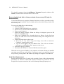
Description/Tutorial..................................................................................................................................27
OS and Drivers.....................................................................................................................................27
Firmware Updates.....................................................................................................................................28
Manual BIOS Update...........................................................................................................................28
Embedded CPU Firmware ...................................................................................................................29
Applications..............................................................................................................................................31
Manual CPU Manager Update.............................................................................................................32
Manual Display Utilities Update..........................................................................................................32
Section 6:
Recovery of pre-installed software ...................................................................................33
Recovering settings and system files ........................................................................................................33
Recovering applications............................................................................................................................33
Recovering the hard disk to factory contents from recovery CD (only for Windows 2000) ....................34
Hard Drive Replacement ..........................................................................................................................34
Section 7:
Getting Assistance from Motorola....................................................................................35
Appendix A:
Safety Instructions........................................................................................................36
Appendix B:
Warranty Information...................................................................................................38
Appendix C:
FCC Information ..........................................................................................................41
Appendix D:
Environment Specifications .........................................................................................42
Appendix E:
CPU Features ...............................................................................................................43
Specifications............................................................................................................................................43
4
MW800 CPU Owner’s Manual
Features.....................................................................................................................................................43
Appendix F:
Auxiliary Port Layout ..................................................................................................46
Appendix G:
Approved Accessories/Options ....................................................................................48
Appendix H:
CPU Factory Default Setting .......................................................................................51
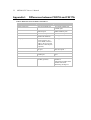
Appendix I:
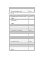
Differences between F5207A and F5217A.......................................................................52
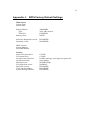
Appendix J:
BIOS Factory Default Settings .........................................................................................53
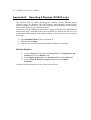
Appendix K:
Operating 2 Displays (F5207A only) ...........................................................................54
Appendix L:
Troubleshooting ...........................................................................................................59
Appendix M:
Acronyms and Abbreviations.......................................................................................61
TABLE OF FIGURES
Figure 1. Main MPS Window........................................................................................................................18
Figure 2. Codeplug Editor .............................................................................................................................19
Figure 3. CPU Manager, Version Tab ...........................................................................................................20
Figure 4. CPU Manager, Lines Control Tab..................................................................................................21
Figure 5. CPU Manager, Power Tab .............................................................................................................21
Figure 6. CPU Manager, Temperature Tab ...................................................................................................22
Figure 7. CPU Manager, Notifications Tab...................................................................................................23
Figure 8. CPU Manager, Logger Tab ............................................................................................................23
Figure 9. Calibration Window .......................................................................................................................24
Figure 10. ExtraKey Configuration ...............................................................................................................25
Figure 11. Support Kit, Main Menu ..............................................................................................................27
Figure 12. EC Loader Setup ..........................................................................................................................30
Figure 13. EC Loader Programming .............................................................................................................30
Figure 14. Successful Programming..............................................................................................................31
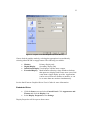
Figure 15. Graphics Controller Properties (Extreme Driver) ........................................................................55
Figure 16. Display Properties (Embedded Driver) ........................................................................................56
Figure 17. Graphics Controller Properties (Embedded Driver).....................................................................57
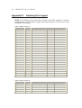
Table 1. F5207A AUX Port...........................................................................................................................46
Table 2. F5217A AUX Port...........................................................................................................................46
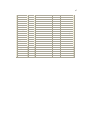
Table 3. Options ............................................................................................................................................48
Table 4. Accessories......................................................................................................................................49
Table 5. Differences between F5207A and F5217A .....................................................................................52
Table 6. Error Messages About Abnormal Conditions..................................................................................59
Table 7. Failure Indications ...........................................................................................................................59
Table 8. Failures Without Notification..........................................................................................................60
5
Using this Manual
Before using this manual and products it describes, be sure to read the Safety
instructions in Appendix A, the Warranty information in Appendix B and the FCC
information in Appendix C.
Who Should Use this Manual
This manual is intended for staff who operate the Mobile Workstation 800 (MW800)
and need to configure, upgrade or maintain its CPU box. This manual assumes the
reader is familiar with the MW800 and basic Windows operations. If this is not the
case, be sure to read the MW800 User’s Guide and documentation that came with
your version of Windows.
For documentation of supplied software applications, refer to the help file attached to
each application.
Manual Introduction
The MW800 mobile workstation consists of three separate interconnected
components: CPU box, Display and Keyboard. This manual only deals with the CPU
box, which is also referred to as either device or CPU in this manual. This manual is
organized as follows:
•
•
•
•
•
•
•
Section 1 provides an overview.
Section 2 provides a description of basic operations.
Section 3 describes various parameters that define CPU configuration when
you turn on your computer.
Section 4 describes a variety of software tools that Motorola provides with the
CPU box.
Section 5 explains software upgrade procedures.
Section 6 provides a view of recovery techniques and ways to reinstall the
complete Windows operating system, device drivers, and applications similar
to original factory setting.
Section 7 describes how to get assistance from Motorola.
The Appendixes contain:
•
•
•
•
•
•
•
Appendix A:
Appendix B:
Appendix C:
Appendix D:
Appendix E:
Appendix F:
Appendix G:
Safety instructions
Warranty information
FCC information
Specifications
CPU Features
Auxiliary port
Approved accessories and options
6
MW800 CPU Owner’s Manual
•
•
•
•
•
•
Appendix H:
Appendix I:
Appendix J:
Appendix K:
Appendix L:
Appendix M:
CPU factory setup
Differences between F5207A and F5217A models
BIOS factory setup
Dual display configuration
Troubleshooting information
Acronyms and Abbreviations
Related Manuals
This manual describes the MW800 CPU box and provides basic operating
instructions. Please note that although this manual refers to hardware and software
components supplied with this product, it does not provide full component
description. For additional information refer to the following documents:
•
•
•
Mobile Workstation 800 Series, User’s Guide
- 6802976C65
Mobile Workstation 800 Series, Owner’s Manual for Display - 6802976C75
Mobile Workstation 800 Series, Installation Manual
- 6802967C20
For documentation on software applications supplied with this product, refer to the
help file attached to each application. This manual is designed to supplement the online help or on-line context-sensitive help installed with every software component.
Please review this information to ensure proper use of the product.
Also, if you need to be able to change the configuration of your device, refer to
•
Mobile Workstation 800 Series,
Maintenance Programming Software, User’s Manual
- 6802976C70
For additional information visit the MW800 home page http://www.motorola.com.
Conventions Used in This Manual
Throughout this publication, you will notice the use of danger and caution marks.
These notations are used to emphasize that safety hazards exist, and care must be
taken. Do not proceed beyond a DANGER or CAUTION until the indicated
conditions are fully understood and met.
The following conventions are used throughout this manual:
Italics
Used for emphasis and for new terms.
Bold
Used to indicate keyboard keys or application buttons.
Program ->
Motorola ->
MW800 CPU->
CPU Manager
Used to designate the location and name of a menu
function. For example, Program -> Motorola ->
MW800 CPU-> CPU Manager launch CPU Manager
program.
7
Note:
Indicates an operational procedure, practice, or
condition to which you should pay special attention.
CAUTION:
Alerts you of conditions, which can result in loss or
corruption of data, or damage to device.
DANGER:
Indicates a potentially hazardous situation, which, if
not avoided, may result in injury. It may also be used to
alert against unsafe practices and property-damageonly accident hazards.
8
MW800 CPU Owner’s Manual
Section 1:
Getting Started
What is the CPU Box?
The Motorola Mobile Workstation 800 (further MW800) series is Motorola's
highest-performing and most rugged data communication and computing solution. It
is specifically designed for the harsh conditions of the mobile environment--areas not
suitable for conventional notebook or desktop computers. Refer to Appendix D for
detailed specifications.
The MW800 CPU Box is available in two models:
•
F5207A - Mobile Workstation
A multipurpose mobile data terminal, which can support the simultaneous
operation of two independent users, each using different display and
keyboard. Among its many interfaces, this model contains video and audio
inputs.
•
F5217A - Mobile Gateway
A multipurpose mobile data terminal with capability to provide seamless
mobility across a number of dissimilar public and private data networks. This
device has three distinct Ethernet ports and provides dead reckoning
intelligence on data coming from the GPS receiver.
This manual covers both CPU models, which share many of the same hardware,
software and mechanical aspects. A summary of differences is shown in Appendix I.
The CPU box provides a wide range of internal and external interfaces (USB 2.0,
Ethernet, RS-232, Firewire) for connection to variety of peripherals. A PC Card slot
situated at the front panel extends the CPU box’s capabilities with PCMCIA-based
devices. Digital video capabilities allow capturing videos from a standard composite
or digital VCR. Appendix E gives details about the CPU box’s features.
An auxiliary port provides interface to vehicle ignition sensor, four TTL level I/O
ports, car battery voltage and 5VDC power outputs, etc. Refer to Appendix F for the
Auxiliary port description.
Using custom-designed cables, the CPU can be connected to the MW800 display or
any standard LCD, CRT or Flat Screen display. A list of approved accessories and
options can be found in Appendix G.
F5207A CPU can support the simultaneous operation of two independent users, each
using different display and keyboard. Refer to Appendix K for details.
9
Section 2:
Basic Operations
This section describes the following operations:
•
•
•
•
•
Power On
Power Off
Standby
Wake Up
Reset
Power On
This chapter describes methods to power on the CPU box in normal and extreme
conditions.
NOTE: Prior to powering on the CPU, ensure that the main power switch on the rear
CPU panel is in the ON position.
Normal operation
The CPU box can be turned on either from the vehicle ignition switch or by the
power button located on the front panel.
•
If the CPU box power is connected directly to the battery (and not through
the ignition switch) and configured to be turned on/off only by the power
button (see section 3, Ignition boot up preference setting is NONE), press
the Power button on the front panel of the CPU box.
•
If the CPU box power is connected through the ignition and configured to be
turned on/off by both the ignition switch and the power button (see section 3,
Ignition boot up preference setting is POWER ON), insert the car key into
the ignition switch and rotate it to ACC position or press the Power button on
the front panel of the CPU box.
•
If the CPU box power is connected through the ignition and configured to be
turned on/off only from the ignition switch (see section 3, Ignition boot up
preference setting is POWER BUTTON LOCK), insert the car key into the
ignition switch and rotate it to ACC position.
When the CPU is turned on, the pre-installed Operating System will be automatically
loaded. This process takes some time; please wait until this process is completed
before using the computer.
10
MW800 CPU Owner’s Manual
Low Temperature Conditions
The device supports working hard disk conditions even if it’s turned off. When the
ambient temperature drops below the low hard disk operational limit, an internal
heater will automatically adjust and maintain the working conditions (see Hard disk
heating when device is off parameter in section 3) for pre-defined time.
•
If the CPU is turned on when Hard disk heating when device is off time-out
has not expired yet and the hard disk temperature is within the operating
range, the CPU will boot up immediately.
•
If the CPU is turned on when Hard disk heating when device is off time-out
occurs and the hard disk temperature is below the low hard disk operational
limit, the CPU will activate the internal heater and will boot up only when the
hard disk temperature returns to the operating range. The heating process
takes some time that can be optimized (see Heater optimization parameter
in section 3); please wait until this process is completed.
NOTE: If the power source is a 9VDC car battery (see Power source parameter in
section 3), the device will not power up when the temperature range is below the low
operational limit.
High Temperature Conditions
The device will be turned on only if an ambient temperature does not exceed the high
operational limit.
NOTE: In extreme conditions, the overall performance of the device (including boot
up time and sustained operations) may be degraded. It will return to normal when the
ambient temperature returns to the operating range.
CAUTION: If overheating, do not turn on the device until it cools down.
Discharged Vehicle Battery
If the power source is a 13.8VDC car battery (see Power source parameter in section
3), the device will normally power up when the voltage level exceeds 10.3VDC.
If the power source is a 9VDC car battery (see Power source parameter in section
3), the device will normally power up when the voltage level exceeds 9VDC.
Shut Down
This chapter describes methods to power off the CPU box in normal and extreme
conditions.
11
Normal Operation
The CPU box can be turned off either by the vehicle ignition switch or by the power
button located on the front panel. The CPU box can also be turned off with the
Windows Shut Down process. Remember to save important information before
turning the device off.
•
If the CPU box is connected via the ignition and configured to be powered
off by the ignition switch (see section 3, Ignition shut down preference
setting is SHUTDOWN), rotate the car key it to OFF position. The device
will automatically shut the Windows down when the Ignition shutdown
time-out expires and power is off.
NOTE: A Windows pop-up dialog will warn you about power off from the
ignition switch. You can cancel this operation up until the Ignition
shutdown time-out has expired.
•
If the CPU box is not connected via the ignition and configured to power off
only by the power button (see section 3, Ignition shut down preference
setting is NONE), briefly press the Power button. The device will shut
Windows down and power off.
•
If the system does not respond, you can turn the device off by pressing and
holding the power button for 6 seconds or more. To permit this option,
Critical turn off parameter (see Section 3) setting should be ENABLE.
CAUTION: This method of hardware power off may damage your hard disk.
Extreme Shut Down
Certain extreme events may cause you device to power off, including ambient
temperature outside the operating limits or discharged car battery.
Selecting desired notifications in the Agent Notification tab of the CPU Manager
application (see Section 4) provides a notice if an extreme event should occur. In this
case you should immediately save your data.
•
Internal temperature drops below the low operational limit.
If during operation the ambient temperature exceeds the operating temperature
range or internal temperature drops below the low operational limit for any
reason, the CPU processor eventually powers off. A message ”CPU
temperature is low. The system will shutdown in 3 minutes. Please save
your work” will warn you about this event.
CAUTION: If extremely low temperature is the reason for the shut down, do
not turn on the device until it heats up.
12
MW800 CPU Owner’s Manual
•
Internal temperature exceeds the high operational limit.
If during operation the ambient temperature exceeds the operating temperature
range or internal temperature exceeds the high operational limit for any
reason, the CPU processor gradually slows down, and eventually powers off.
A message ”CPU temperature is high. The system will shutdown in 3
minutes. Please save your work” will warn you about this event.
CAUTION: If overheating is a reason for the shut down, do not turn on the
device until it cools down.
•
Vehicle battery is discharged.
If, during normal operation, the battery voltage drops below 10.5VDC the
device will provide Low Battery indication (the MW800 display power
indicator blinks yellow).
A message ”Vehicle Battery is Low. The system will shutdown in 3
minutes. Please save your work” will warn you about this event.
If the voltage continues to drop, the device automatically powers off at
8.5VDC.
•
Drops in car battery voltage.
If battery voltage drops below the 8.8V limit for 20 seconds or more, the
device will execute critical shut off and power itself off.
Power Management
This chapter describes low-power mode (standby) and resume normal operating
mode. In low-power state, the CPU enters a power-saving mode, turns off the display
backlight and slows down the CPU speed; the internal radios remain powered on. To
resume normal operation, touch the display panel or press any display function key.
Standby
The CPU box can enter low-power state (standby) either manually or automatically
when System Standby time-out occurs. The CPU will enter Standby mode via the
following methods:
•
•
•
Press the Standby button on the right side of the MW800 display.
Press on the Power button. The CPU can be configured to enter Standby mode
when you press the Power button. For details about this option, refer to the
help file attached to Power Options (Start -> Settings -> Control Panel ->
Power Options).
The device can be configured to automatically enter a low-power state when
System standby time-out occurs. For details about this option, refer to the help
file attached to Power Options (Start -> Settings -> Control Panel -> Power
Options).
13
Resume
If the device is in Standby mode, the following methods will resume it:
•
•
•
•
•
•
•
•
•
Ring Indicator from a serial port
USB bus activity
An input from the keyboard
Changing a touch pad position
A contact to the touch panel of the MW800 display
Pressing the Emergency key of the MW800 display
Pressing the Function key of the MW800 display
LAN (Wake on LAN message)
Power button (if configured)
If the CPU box configuration allows wake up from a serial port (see section 3, Radio
ring indicator (RI) setting is ENABLE, System ring indicator (RI) mask setting is
DISABLE), the CPU will resume when a device connected to a serial port activates
the RI line.
A USB device can wake the CPU out of standby if its setting specifies the operating
system to do so. To enable this feature, Allow this device to bring the computer
out of standby option (Power Management tab in Properties) should be selected.
For details about this option, refer to the help file attached to the Properties of the
device.
A Network (Ethernet) device can resume the CPU from standby if its setting
specifies the operating system to do so. To enable this feature, Allow this device to
bring the computer out of standby option (Power Management tab in
Properties) should be selected. For details about this option, refer to the help file
attached to the Properties of the device.
Pressing of the Power button will bring the computer out of standby if its setting
specifies the operating system to do so. For details about this option, refer to the help
file attached to Power Options (Start -> Settings -> Control Panel -> Power
Options).
Resetting
You may have to reset the CPU when an error occurs and the program you are using
locks up. Be aware that the system may have been processing data when it locked up.
If you are sure the system operation has stopped and you cannot use the ‘Restart’
function of the operating system, reset your device. Be aware that resetting will
cause unsaved data to be lost.
To reset the device, press the <Ctrl+Alt+Del> keys, and select the Restart option
from the Windows shut down screen.
14
MW800 CPU Owner’s Manual
CAUTION: If the system does not respond, you can turn the device off by pressing
and holding the power button for 6 seconds or more. Be aware, this method of
hardware power off may damage your hard disk.
15
Section 3:
CPU Configuration
The CPU has a protected memory area to store the configuration parameters
accessed when you turn it on. That binary-format data contains basic information
about CPU capabilities including general settings, power-up, power-off modes, etc.
This chapter describes the various configuration parameters that can be selected and
modified as required.
CPU Configuration Parameters
Power source
Provides capability to select a power source: either 13.8VDC or 9VDC car batteries.
Factory setting is 13.8VDC.
NOTE: if 9VDC battery is selected, power loss compensation during engine
cranking will be not supported.
Turn-off command from display
Normally, when the MW800 display encounters a hardware problem, it can turn the
CPU off. This parameter enables or disables this feature. Factory setting is
ENABLE.
Critical turn off
Normally, if the system does not respond, you can turn the device off by pressing
and holding the power button for 6 seconds or more. This parameter enables or
disables this feature. Factory setting is ENABLE.
Power button preference
Normally, you can turn the device on and off by pressing the power button. This
parameter enables or disables this feature. Factory setting is ENABLE.
NOTE: If you disable this feature, only the ignition switch can turn the device on.
Make sure, that Ignition boot up preference setting is POWER ON.
Ignition boot up preference
Selects desired CPU action when turning the ignition switch on. The following
options are available:
•
•
•
NONE
POWER ON
Ignore turning the ignition switch on.
Boot up the device if it’s powered off; ignore if it’s
already powered on.
POWER BUTTON
LOCK
Block the Power Button until you turn on the ignition
switch.
Factory setting is POWER ON.
16
MW800 CPU Owner’s Manual
Ignition shut down preference
Selects desired CPU action when turning the ignition switch off. The following
options are available:
•
•
NONE
SHUTDOWN
Ignore turning the ignition switch off.
Shut the device down when the ignition switch is turned
off. If this option is selected, set Ignition shutdown timeout, which specifies the period to elapse between turning
off the ignition switch and the CPU shutting down.
Factory setting is NONE.
Ignition shutdown timer
Selects the amount of time to elapse between turning the ignition switch off and CPU
shutting down. This parameter may vary from 0 to 127 seconds or minutes. Factory
setting is 3 minutes.
WLAN adapter switch
Turns internal mini-PCI wireless LAN adapter on and off. Factory setting is ON.
Radio status on power up
Selects the initial state of the internal WAN (GPRS, iDEN or Private DataTAC)
radio. Factory setting is ON.
Main radio power switch
The internal radio is connected to or disconnected from a power source. This
parameter turns the radio power switch on and off. Factory setting is ON.
GPO0 state on power up
Defines initial state of the general-purpose GPO0 output at the auxiliary connection.
Factory setting is OFF.
GPO1 state on power up
Defines initial state of the general-purpose GPO1 output at the auxiliary connection.
Factory setting is OFF.
Auxiliary 5V output
Enables or disables 5VDC output at the auxiliary connection. Factory setting is
ENABLE.
Auxiliary 12V output
Enables or disables the car battery voltage output at the auxiliary connection. Factory
setting is ENABLE.
GPS state on power up
17
Selects initial mode of a GPS receiver if your CPU is fitted with the internal Trimble
GPS unit. Factory setting is OFF.
GPS mode
This parameter is pertinent if your CPU is fitted with the internal Trimble GPS
device. It selects the standard protocol used by GPS receiver to transmit data. The
NMEA and TSIP/TAIP options are available. Factory setting is TSIP/TAIP for
F5207A and NMEA for F5217A.
Radio ring indicator (RI)
Enables or disables wake-up from the RI line of the serial COM3 port. Factory
setting is ENABLE.
System ring indicator (RI) mask
Masks Ring Indicator from any serial port. When masking is disabled, RI from any
serial port will wake up the device. Factory setting is DISABLE.
Note: for serial COM3 port, see also Radio ring indicator (RI) parameter.
iDEN programming mode
This parameter is pertinent if the device is fitted with an internal iDEN modem. It
turns on or off a special programming mode of the iDEN modem. Factory setting is
OFF.
SB9600 mode
This parameter is pertinent if the device is fitted with an internal iDEN modem and
allows a data in SB9600 format to be encapsulated. Factory setting is ON.
Heater optimization
The CPU has internal hard disk heater, which allows operating in low temperatures.
This parameter optimizes automatic heating, based on the ambient temperature in
your area. Factory setting is 0°F.
Hard disk heating when device is off
An internal automatic hard drive heater allows the CPU to operate properly in low
temperatures. When the device is turned off, an automatic heater will maintain the
hard drive temperature within the operating range for a certain period of time set by
this parameter. The period range is 0 to 16 hours. Factory setting is 16 hours.
CPU serial number
This read-only field shows the CPU serial number.
Refer to Appendix H for factory setting of the CPU configuration parameters.
18
MW800 CPU Owner’s Manual
BIOS Setup
The BIOS is a program stored on a Flash chip on the motherboard with a default
configuration that starts when you turn on the CPU.
The device provides a BIOS Setup Utility that enables the selection and modification
of different BIOS setup parameters. Note that incorrect BIOS changes can prevent
the device from working. Factory BIOS setting can be found in Appendix J.
CPU Configuration Change
This chapter describes software tools and the most common methods to change CPU
configuration.
Maintenance Programming Software
The Maintenance Programming Software enables modification of the configuration
that starts when you turn the CPU on. Use the MPS context-sensitive on-line help
information for assistance in configuring the device.
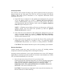
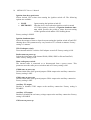
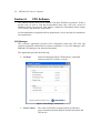
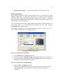
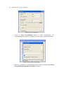
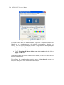
How to Modify Configuration Parameters
To modify the configuration parameters perform the following:
•
Double-click on the MPS icon; main MPS window appears on the screen.
Figure 1. Main MPS Window
•
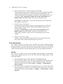
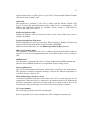
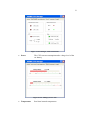
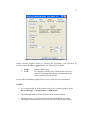
Click on Codeplug Editor
19
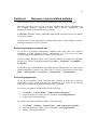
Figure 2. Codeplug Editor
To modify configuration parameters use the MPS tool as the following:
•
•
•
•
•
Click on Read from CPU to read the codeplug parameters. If your device is
successfully read, you will see CPU parameters.
Click on Save to file to backup the original codeplug data.
Modify a parameter per your selection.
Click on Write to CPU to program the device.
If the device is successfully programmed, the following message appears.
CAUTION: Incorrect configuration can make the device inoperable. Please, make
sure to acquire the appropriate codeplug. Always make a backup copy in case an
error is made during the update.
Note: For details refer to Maintenance Programming Software User’s Manual.
20
MW800 CPU Owner’s Manual
Section 4:
CPU Software
This manual assumes that you are familiar with basic Windows operations. If this is
not the case, be sure to read the documentation that came with your version of
Windows before you proceed. This chapter contains the information about unique
CPU software and firmware components.
For documentation of supplied software applications, refer to the help file attached to
each application.
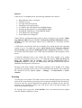
CPU Manager
This software application provides basic information about the CPU unit and
selection of desired notifications in extreme conditions. To run CPU Manager, click
MW800 CPU Manager icon from the Start menu.
This application provides the following:
•
Versions
General information about CPU hardware, embedded
firmware and CPU software versions
Figure 3. CPU Manager, Version Tab
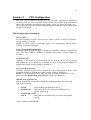
•
Lines Control
The status of GPI lines, manual control of GPO lines,
power on and off internal WWAN and WLAN radios and
GPS device
21
Figure 4. CPU Manager, Lines Control Tab
•
Power
The CPU current consumption and a voltage level of the
car battery
Figure 5. CPU Manager, Power Tab
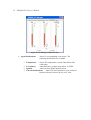
•
Temperature
Real time internal temperatures
22
MW800 CPU Owner’s Manual
Figure 6. CPU Manager, Temperature Tab
•
Agent Notifications
◊
◊
◊
◊
Temperature
Alerts if a corresponding event occurs. The
following notifications are available:
- when CPU temperature exceeds either limit of the
valid range.
Low battery
- when the battery voltage drops below 10.5VDC.
Ignition
- when you turn off the ignition switch.
Current Notifications - when CPU box experiences over-current of
hard drive heater, firewire device or PC card.
23
Figure 7. CPU Manager, Notifications Tab
•
Logger
Troubleshooting tool allowing documentation of extreme
events into a log file
Figure 8. CPU Manager, Logger Tab
24
MW800 CPU Owner’s Manual
MW800 Display Utilities
This application provides the following capabilities:
•
Calibration Tool
•
ExtraKey Application
•
•
MW Display Tester
Volume Bar
calibrates the touch screen interface to the display
monitor
configures the MW800 display functional buttons
for other Windows applications
troubleshoots several display problems
sets of the current volume level
Calibration
Sometimes there is a need to calibrate the touch panel attached to the display
monitor, i.e. to adjust the pushed position of the panel and its display position of the
monitor. Even if the touch panel has same dimensions as the display monitor, there
may be minor variations between corresponding data points due to resistance
variance of each panel.
When you use touch panel module for the first time, or, when there is discrepancy
between the touched and displayed positions, calibration is required. This needs to be
done only once, whereupon the calibration data is stored. The CPU will
automatically calculate the touched position on display monitor.
This adjustment may be executed with the MW800 Display Calibration Tool.
Figure 9. Calibration Window
This utility performs the following:
•
Calibrate Device
•
Reset Device
•
Simulate Calibration
•
Test
calibrates the touch screen and saves calibration
data
nullifies calibration parameters in the MW800
display codeplug
simulates calibration of the touch screen without
saving calibration
briefly tests of the touch screen after calibration
25
•
Double-Click Setting
calibrates the double-click on the touch screen
ExtraKey Application
The ExtraKey Application allows display function keys to be configured for other
Windows applications. It allows the function key to operate like the standard
keyboard hotkey, launch any application (like Notepad or Calculator) or blank the
display. ExtraKey application's desktop toolbar is situated on one of the edges of the
screen (default - the bottom edge).
You can customize the Extrakey using Configuration window, launched either from
the Control Panel, or by left-clicking the ExtraKey tray icon and choosing
Configuration in the pop-up menu.
Each display function key can be mapped either to a hot key (such as Ctrl + X, F1
etc.), to a file (as a shortcut), or to the display switch:
Figure 10. ExtraKey Configuration
How to set a shortcut to the hot key
•
•
•
Choose Hot Key in the Map to drop-list.
Move the cursor to Press new hotkey field and right-click once to activate it.
Press the desired key on the keyboard. Field Name defines how the Extrakey
Bar button will be named (this is optional).
How to set a shortcut to the application
•
•
Choose File in the Map to drop-list.
Enter the full path name of the file to be opened or click the button to browse.
Field Name defines how the Extrakey Bar button will be named (this is
optional).
26
MW800 CPU Owner’s Manual
How to set a shortcut to the display switch
•
•
Choose Display switch in the Map to drop-list.
Field Name defines how the Extrakey Bar button will be named (this is
optional).
The ExtraKey Application on-line help provides context-sensitive information.
Please, read this information to ensure proper operation of the device.
Display Tester
This tool is simple test application for troubleshooting certain display features. This
tool is for display diagnostics purposes, only.
Volume Bar
This application sets the volume level. The Volume window allows color
modifications and pops-up on every volume change. If your display unit includes the
BlueTooth feature, this application also allows commutation of audio stream to the
BlueTooth device.
27
Section 5:
Software/Firmware Upgrade
Software upgrades keep your computer up-to-date. All software components, utilities
and applications described in this chapter are PC-based, running under Windows
2000 and Windows XP operating systems on the MW800 series or compatible
platform.
The MW800 Support CD-ROM part No. FVN5413A is an auto-run software
package. Use this kit when you installing or updating unique software and firmware
components in your device.
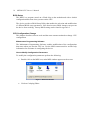
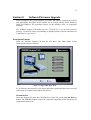
Description/Tutorial
Insert the MW800 Support CD into the CD drive. The Main Menu screen
automatically appears as shown:
Figure 11. Support Kit, Main Menu
To perform the desired action, click on the particular option and follow the on-screen
instructions to continue and complete the process.
OS and Drivers
Insert the Support Kit into the CD-ROM drive and click on the OS and Drivers
button. The MW800 Support kit provides automatic upgrading of the following OS
components and drivers:
28
MW800 CPU Owner’s Manual
•
Chipset Installation
•
Extreme Graphics
•
Embedded Graphics
•
•
LAN
WLAN
•
•
•
Sound driver
Video Capture
Windows SP
Updates the Windows *.INF files in your device.
The INF files inform the operating system how to
properly configure the chipset for specific
functionality, such as USB and core PCI.
Updates or install the Extreme Graphics video
driver. The Extreme Graphics offers advanced
features that support the latest 3D, 2D, and videoplayback applications targeted for all users.
Updates or install the Embedded video
driver. The Embedded video driver provides
capability to work with the secondary RGB display.
Updates the LAN driver in your device.
Updates or install WLAN driver for the Intel®
PRO/Wireless 2100 Network Connection wireless
network adapter.
Updates the sound driver in your device.
Updates Conexant video capturing driver.
Updates Windows XP Service Pack 2 and Windows
2000 Service Pack 4 (accordingly to the installed
Operation System).
Firmware Updates
Insert the Support Kit into the CD-ROM drive and click on the Firmware Updates
button. The MW800 Support Kit provides automatic upgrading of the following
unique firmware components:
•
•
•
BIOS
CPU
12’1’ Display
•
8.4’ Display
•
MPS
•
PRM240
Updates the BIOS in your device.
Updates CPU Embedded Controller firmware
Updates the embedded controller firmware in the
12.1’ display
Updates the embedded controller firmware in the
8.4’ display
Launches Maintenance Programming Software to
enable the MW800 field configuration by
modifying CPU and Display internal parameters.
Updates PRM240 (internal DataTAC modem)
firmware
Manual BIOS Update
For manual BIOS update, launch the WinPhlash tool from the Support Kit. You can
perform two procedures with WinPhlash:
•
Backup your current BIOS.
29
•
Write new BIOS to the mainboard.
CAUTION: Writing new BIOS to the flash chip is a very sensitive procedure,
improper BIOS upgrade could make the device inoperable.
Note: Always back up your current BIOS. If something goes wrong, the previous
one can always be restored.
If upgrading of the BIOS is required, carry out the following steps:
•
•
•
•
•
•
•
•
Close all other programs.
Go to Program menu and click WinPhlash to execute the program. Main
window will appear on the screen.
Select the procedure you want to perform:
Backup the existing BIOS and flash a new BIOS with new settings
Backup the existing BIOS Only.
Specify the name of the backup file for the existing BIOS in the first edit field
or use the Browse button to find the file.
Specify the name of the new BIOS file in the second edit field or use the
Browse button to find the file.
Press the Flash BIOS (or Backup Now) button. A message displays asking
for confirmation to continue. You can continue or cancel.
Press OK on the confirmation box to start the procedures you selected.
Reboot your device when the procedure is completed.
Note, do not interrupt the program before task completes.
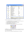
Embedded CPU Firmware
For manual CPU firmware update, launch the MPS and then the EC Loader tool.
This tool provides the ability to program a S-Record file to EC memory flash. The
EC Loader allows downloading the firmware into the device only if the firmware is
compatible with the type of embedded CPU controller. In case of an incompatibility,
the loader reports an error and prevents user errors, such as improper file download.
Set programming and connection settings as shown:
•
•
•
•
•
Select serial COM4 (F5207A) or COM5 (F5217A) port for communication
with embedded controller.
Select Internal connection type.
Select CPU firmware target.
Select a file to be downloaded into embedded controller.
Select Overwrite Codeplug if you want to replace the configuration
parameters in your device with factory default. Otherwise, keep it unselected.
30
MW800 CPU Owner’s Manual
Figure 12. EC Loader Setup
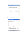
•
Click on Start Programming button to begin programming. EC
Programming dialog appears; the progress bar will show programming status.
Figure 13. EC Loader Programming
•
Wait for completion of programming process. When completed EC Flash
Programming has passed successfully will appear.
31
Figure 14. Successful Programming
Applications
Insert the Support Kit into the CD-ROM drive and click on the Applications button.
The MW800 Support kit provides automatic upgrading of the following applications
and utilities:
•
•
•
•
•
•
•
CPU Manager
Updates the CPU Manager application providing
basic information about the CPU unit and selection
of desired notifications in extreme conditions
Display Utilities
Updates Display utilities to extend the display
capabilities
vRCH
Installs or updates the vRCH application.
This software application communicates with the
radio unit and provides a GUI interface of the radio
control head, allowing full control of the radio via
the display touch panel.
Bluetooth Package
Installs or updates the BluePC™ Bluetooth stack
driver solution to enable a wireless connection
between the MW800 and other Bluetooth devices.
WM Capture
Installs or updates the Windows Media (WM)
Capture 9 Series tool allowing video content
authors to capture uncompressed AVI files with up
to 24-bit resolution and sampling rates up to 192
KHz.
Windows Media Player Installs or updates the Windows Media Play9
Series to provide audio and video playback for
Windows and the Web.
Microsoft Directx9
Installs or updates the DirectX suite of multimedia
32
MW800 CPU Owner’s Manual
application programming interfaces (API’s) built
into Microsoft Windows operating systems.
NOTE: Microsoft WM Capture Tool, Windows Media Player 9 and Microsoft
DirectX 9.0c are available only for Windows 2000.
Manual CPU Manager Update
You can manually update the CPU Manager in your device as follows:
•
•
Remove the current version of CPU Manager.
Go to Control Panel -> Add and Remove Programs, select MW800 CPU
Manager and click Change/Remove button.
Install the current version of CPU Manager.
Double click on the icon of new version of MW800 CPU Manager and follow
on-screen instructions.
Manual Display Utilities Update
You can manually update the Display Utilities in your device as follows:
•
•
Remove the current version of MW800 Display utilities.
Go to Control Panel -> Add and Remove Programs, select MW800
Display Utilities and click Change/Remove button.
Install the new version of MW800 Display utilities.
Double click on the icon of new version of MW800 Display Utilities and
follow on-screen instructions.
33
Section 6:
Recovery of pre-installed software
This section provides a view of general maintenance and recovery techniques.
Motorola provides a recovery CD with your computer that allows reinstallation of
the complete Windows operating system, device drivers, applications, and
parameters similar to the default factory settings.
CAUTION: Personal settings, additional applications and data will be lost during
recovery procedure.
If you need to recover applications, configurations, data, or other settings, you have
other non-destructive recovery options.
Recovering settings and system files
If you have experienced intermittent problems that came after new software
installation or some change in device configuration, you can revert to previous
working settings and undo harmful changes on your device.
If you are using Windows 2000, you can fix the problem by using the ConfigSafe
program. To access ConfigSafe program click Start -> Programs -> ConfigSafe ->
ConfigSafe.
In Windows XP, System Restore tool might fix the problem and revert the system
settings and registry entries to an earlier state. To access System Restore tools click
Start -> All Programs -> Accessories -> System Tools -> System Restore
Recovering applications
If you have reinstalled system files and your personal settings, but a software
application or device driver that you have installed on your device is not working
correctly, recovering the application might resolve problems.
To remove a program in Windows XP, do the following:
•
•
•
Click Start -> Control Panel -> Add or Remove Programs.
Find a program you want to remove and then click Change/Remove.
Follow on-screen instructions.
To remove a program in Windows 2000, do the following:
•
•
•
Click Start -> Settings -> Control Panel -> Add or Remove Programs.
Find a program you want to remove and then click Change/Remove.
Follow on-screen instructions.
34
MW800 CPU Owner’s Manual
To reinstall a program, from the Add/Remove Programs Properties window, click
Install, and then follow the instructions on the screen.
Recovering the hard disk to factory contents from recovery CD (only for
Windows 2000)
If your hard disk data is completely damaged and none of above procedures helps,
you can recover the hard disk software image similar to the initial factory install with
the recovery CD.
To recover the hard disk, do the following:
• Turn the CPU off.
• Connect USB CD-ROM drive to your device
• Insert recovery CD into USB CD-ROM drive
• Turn on your computer.
• Watch the display carefully. When the M-logo is displayed, press the F2
button to enter BIOS setup.
• Make your CD-ROM drive a bootable device as follows: Set the first boot
priority for USB device and exit from BIOS setting with configuration save
and reboot.
• Follow the instructions on the screen:
Press the ‘Y’ key when "Copy disk image from CD to hard disk.
Continue?” appears on the screen.
Type the word "agree" and press Enter when "This will erase all data...
type agree to confirm this action" appears on the screen.
• Wait until copying is finished.
• Disconnect the USB device from the MW800 and reboot again
When the recovery process finishes, your computer will restart with the pre-installed
operating system, drivers, and software. If automatic restart is not performed, restart
the system by pressing Ctrl + Alt + Del or by turning the computer off and then on.
Hard Drive Replacement
Replace the hard disk only if it needs to be repaired (if none of the aforementioned
procedures are effective). Understand that the hard disk bay connector was not
designed for frequent connections and could be damaged through improper use.
35
Section 7:
Getting Assistance from Motorola
For your convenience, the Motorola Web site provides up-to-date information about
the MW800.
The address for MW800 home page is http:/www.motorola.com.
This site includes general information about the device, as well as answers to
questions regarding operational issues with the MW800. The site also provides the
following:
•
•
•
Recent software / application updates
Updated embedded firmware for your computer
The latest device drivers
36
MW800 CPU Owner’s Manual
Appendix A: Safety Instructions
DANGER:
Reduce the risk of fire or electric shock by following basic safety instructions:
• Do not use your device during electrical storms.
• Do not connect or disconnect cables while you device is turned on.
• Protect your device from liquids. Keep your device away from water.
• Do not use any power cord where input or output pins show signs of corrosion
or overheating.
• Be sure that all power cord connections are securely plugged into receptacles.
• Never coil a power cord.
• Always route a power cord and communication cables so they will not be
damaged.
DANGER:
To avoid shock hazard, disconnect the power cable and all communication cables
opening the device.
DANGER:
Electric current in power and communication cables is hazardous. To prevent shock
hazard, follow the installation methods recommended in the Installation Manual.
DANGER:
An improperly grounded device is hazardous. To prevent shock hazard, follow the
installation methods recommended in the Installation Manual.
CAUTION:
The device dissipates heat during normal operation. When the device is operating, do
not allow it to contact any part of your body for an extended period of time – it could
cause discomfort.
CAUTION:
The device generates heat when on. Never block or cover ventilations slots and fans.
CAUTION:
The device is sensitive to uncontrolled shut down. Never turn off the device by
turning off the power supply or by disconnection of the power cable.
CAUTION:
Hard drive performance and lifetime could be shortened if the device is not used for
long period of time. Do not leave the device unused for more than 3 months.
CAUTION:
37
If you opened the device to add or upgrade a memory card or Mini PCI card or any
other component, do not use your device until you have re-assembled the entire unit.
Never use the device when cover(s) is open.
CAUTION:
The CMOS battery can degrade when your device is not used for a long period of
time. Leaving a battery in a discharged state could shorten a lifetime of the battery.
CAUTION:
The device automatically shuts down when the internal temperature exceeds the
upper limit of the valid range. Under this condition, do not turn the device on until it
cools down.
CAUTION:
Avoid inserting any card into PC card slots at an angle – it could damage connectors
in the device.
CAUTION: Normally, if the system does not respond, you can turn the device off
by pressing and holding the power button for 6 seconds or more. Be aware, this
method of hardware power off may damage the hard disk.
CAUTION: Do not insert or remove a PC card when the MW800 is in Standby
mode. Before you insert or remove a card, make sure that you exit all software
applications that access the card.
CAUTION: When replacing a device, verify that it is hot swappable. Otherwise,
turn off your device prior to replacement.
CAUTION: An incorrect configuration can make your device inoperable. Please,
make sure to acquire the appropriate codeplug. Always make a backup copy in case
you have made an error during the update.
38
MW800 CPU Owner’s Manual
Appendix B: Warranty Information
EPS – 34440- B
This warranty applies within the fifty (50) United States, the District of Columbia and
Canada.
LIMITED WARRANTY
MOTOROLA COMMUNICATION PRODUCTS
If the affected product is being purchased pursuant to a written Communications System
Agreement signed by Motorola, the warranty contained in that written agreement will
apply. Otherwise, the following warranty applies.
I. WHAT THIS WARRANTY COVERS AND FOR HOW LONG:
Motorola Inc. or, if applicable, Motorola Canada Limited ("Motorola") warrants the
Motorola manufactured radio communications product, including original equipment
crystal devices and channel elements ("Product"), against material defects in material and
workmanship under normal use and service for a period of One (1) Year from the date of
shipment. Motorola, at its option, will at no charge either repair the Product (with new or
reconditioned parts), replace it with the same or equivalent Product (using new or
reconditioned Product), or refund the purchase price of the Product during the warranty
period provided purchaser notifies Motorola according to the terms of this warranty.
Repaired or replaced Product is warranted for the balance of the original applicable
warranty period. All replaced parts of the Product shall become the property of Motorola.
This express limited warranty is extended by Motorola to the original end user purchaser
purchasing the Product for purposes of leasing or for commercial, industrial, or
governmental use only, and is not assignable or transferable to any other party. This is the
complete warranty for the Product manufactured by Motorola. Motorola assumes no
obligations or liability for additions or modifications to this warranty unless made in
writing and signed by an officer of Motorola.
Unless made in a separate written agreement between Motorola and the original end user
purchaser, Motorola does not warrant the installation, maintenance or service of the
Product. Motorola cannot be responsible in any way for any ancillary equipment not
furnished by Motorola, which is attached to or used in connection with the Product, or for
operation of the Product with any ancillary equipment, and all such equipment is
expressly excluded from this warranty. Because each system, which may use the Product,
is unique, Motorola disclaims liability for range, coverage, or operation of the system as a
whole under this warranty.
II. GENERAL PROVISIONS:
This warranty sets forth the full extent of Motorola’s responsibilities regarding the
Product. Repair, replacement or refund of the purchase price, at Motorola’s option, is the
exclusive remedy. THIS WARRANTY IS GIVEN IN LIEU OF ALL OTHER EXPRESS
WARRANTIES. MOTOROLA DISCLAIMS ALL OTHER WARRANTIES OR
CONDITIONS, EXPRESS OR IMPLIED, INCLUDING THE IMPLIED
WARRANTIES OR CONDITIONS OF MERCHANTABILITY AND FITNESS FOR A
PARTICULAR PURPOSE. IN NO EVENT SHALL MOTOROLA BE LIABLE FOR
39
DAMAGES IN EXCESS OF THE PURCHASE PRICE OF THE PRODUCT, FOR
ANY LOSS OF USE, LOSS OF TIME, INCONVENIENCE, COMMERCIAL LOSS,
LOST PROFITS OR SAVINGS OR OTHER INCIDENTAL, SPECIAL, INDIRECT OR
CONSEQUENTIAL DAMAGES ARISING OUT OF THE USE OR INABILITY TO
USE SUCH PRODUCT, TO THE FULL EXTENT SUCH MAY BE DISCLAIMED BY
LAW.
III. HOW TO GET WARRANTY SERVICE:
Purchaser must notify Motorola’s representative or call Motorola’s Customer Response
Center at 1-800-247-2346 within the applicable warranty period for information
regarding warranty service.
IV. WHAT THIS WARRANTY DOES NOT COVER:
A) Defects or damage resulting from use of the Product in other than its normal and
customary manner.
B) Defects or damage from misuse, accident, water, or neglect.
C) Defects or damage from improper testing, operation, maintenance, installation,
alteration, modification, or adjustment.
D) Breakage or damage to antennas unless caused directly by defects in material
workmanship.
E) A Product subjected to unauthorized Product modifications, disassemblies or repairs
(including, without limitation, the addition to the Product of non-Motorola supplied
equipment) which adversely affect performance of the Product or interfere with
Motorola’s normal warranty inspection and testing of the Product to verify any warranty
claim.
F) Product, which has had the serial number removed or made illegible.
G) Batteries (they carry their own separate limited warranty).
H) Freight costs to the repair depot.
I) A Product, which, due to illegal or unauthorized alteration of the software/firmware in
the Product, does not function in accordance with Motorola’s published specifications or
with the FCC type acceptance labeling in effect for the Product at the time the Product
was initially distributed from Motorola.
J) Scratches or other cosmetic damage to Product surfaces that do not affect the operation
of the Product.
K) That the software in the Product will meet the purchaser’s requirements or that the
operation of the software will be uninterrupted or error-free.
L) Normal and customary wear and tear.
M) Non-Motorola manufactured equipment unless bearing a Motorola Part Number in
the form of an alphanumeric number (i.e., TDE6030B).
V. GOVERNING LAW
In the case of a Product sold in the United States and Canada, this Warranty is governed
by the laws of the State of Illinois and the Province of Ontario, respectively.
VI. PATENT AND SOFTWARE PROVISIONS:
Motorola will defend, at its own expense, any suit brought against the end user purchaser
to the extent that it is based on a claim that the Product or its parts infringe a United
40
MW800 CPU Owner’s Manual
States patent, and Motorola will pay those costs and damages finally awarded against the
end user purchaser in any such suit which are attributable to any such claim, but such
defense and payments are conditioned on the following:
A) that Motorola will be notified promptly in writing by such purchaser of any notice of
such claim;
B) that Motorola will have sole control of the defense of such suit and all negotiations for
its settlement or compromise; and
C) should the Product or its parts become, or in Motorola's opinion be likely to become,
the subject of a claim of infringement of a United States patent, that such purchaser will
permit Motorola, at its option and expense, either to procure for such purchaser the right
to continue using the Product or its parts or to replace or modify the same so that it
becomes non-infringing or to grant such purchaser a credit for the Product or its parts as
depreciated and accept its return. The depreciation will be an equal amount per year over
the lifetime of the Product or its parts as established by Motorola. Motorola will have no
liability with respect to any claim of patent infringement which is based upon the
combination of the Product or its parts furnished hereunder with software, apparatus or
devices not furnished by Motorola, nor will Motorola have any liability for the use of
ancillary equipment or software not furnished by Motorola which is attached to or used in
connection with the Product. The foregoing states the entire liability of Motorola with
respect to infringement of patents by the Product or any of its parts thereof.
Laws in the United States and other countries preserve for Motorola certain exclusive
rights for copyrighted Motorola software such as the exclusive rights to reproduce in
copies and distribute copies of such Motorola software. Motorola software may be used
only in the Product in which the software was originally embodied and such software in
such Product may not be replaced, copied, distributed, modified in any way, or used to
produce any derivative thereof. No other use including, without limitation, alteration,
modification, reproduction, distribution, or reverse engineering of such Motorola
software or exercise of rights in such Motorola software is permitted. No license is
granted by implication, estoppel or otherwise under Motorola patent rights or copyrights.
41
Appendix C: FCC Information
CAUTION: Changes or modifications made in the CPU box or Display, not expressly
approved by Motorola, will void the user's authority to operate the equipment
EPS – 48759 – O
FCC INTERFERENCE WARNING
The FCC requires that manuals pertaining to Class A and Class B computing devices
must contain warnings about possible interference with local residential radio and TV
reception. This warning reads as follows:
NOTE: This equipment has been tested and found to comply with limits for a Class B
digital device, pursuant to Part 90 of the FCC Rules. These limits are designed to provide
reasonable protection against harmful interference when the equipment is operated in a
commercial or residential environment. This equipment generates, uses, and can radiate
radio frequency energy and, if not installed and used in accordance with the instruction
manual, may cause harmful interference to radio communications.
For detailed product safety and RF exposure for mobile stations with two-way radios
installed in vehicles, refer to Electromagnetic Emission (EME) safety leaflet, Motorola
publication number 68P02967C16.
FCC Compliance Notice
The FCC requires that manuals pertaining to Class A and Class B computing devices
must contain warnings about possible interference with local residential radio and TV
reception. This warning reads as follows:
NOTE: This equipment has been tested and found to comply with limits for a Class B
digital device, pursuant to Part 90 of the FCC Rules. These limits are designed to provide
reasonable protection against harmful interference when the equipment is operated in a
commercial or residential environment. This equipment generates, uses, and can radiate
radio frequency energy and, if not installed and used in accordance with the instruction
manual, may cause harmful interference to radio communications.
This device complies with Part 90 of the FCC Rules. Operation is subject to the following
two conditions:
(1) This device may not cause harmful interference.
(2) This device must accept any interference received, including interference that may
cause undesired operation.
For detailed product safety and RF exposure for mobile workstations, with two-way
radios, installed in vehicles, refer to Electromagnetic Emission (EME) safety leaflet,
Motorola publication number 68P02967C16.
42
MW800 CPU Owner’s Manual
Appendix D: Environment Specifications
•
•
•
•
•
Storage temperature:
Operating temperature:
Humidity:
Shock:
Vibration:
•
•
Drip:
Dust:
•
Salt Fog:
•
•
Flammability:
Solar Radiation:
•
Shock Crash Hazard:
-40° to 158° F (-40° to +70° C)
-22° to 158° F (-30° to +70° C)
90 to 95% Relative humidity at 50° C for 8 hours
20g peak 1/2 sine wave @ 11ms, 30 impacts
Per TIA/EIA 603 Paragraph 3.3.4 and MIL-STD810F method 514.5, Category I
Per MIL-STD-810F method 506.4 Procedure III
Blowing 5 hours in dust (140 mesh silica flour),
laden atmosphere dust agitation time is for 2
seconds every 15 minutes
8 hours, 5% Sodium Chloride at 35°C, after
exposure, per MIL-STD-810F 505.4, Procedure I
Per UL94-HB
7 cycles of 24 hours with no functional degradation
per MIL-STD-810F, 505.4, Procedure I
75 g, 6 ms per MIL-STD-810F method 516.5,
Procedure V
Note: UL certification is available only to +50°C, though continued operations are
available above this limit.
43
Appendix E: CPU Features
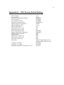
Specifications
Size
• Width: 7.75” (19.7 cm)
• Depth: 9.45” (24.0 cm)
• Height: 2.74” (6.95 cm)
Weight
• CPU:
7.7 pounds (3.5 Kg)
Power source
• Vehicle battery, negative ground.
• Voltage Input Variation 13.8 VDC ± 20% with no loss of functionality.
• Power loss compensation during engine cranking in standard 13.8 VDC
battery system.
• Current consumption at 13.8 VDC:
Maximal
3A
Typical
1.5A
Standby
0.4 A
Power off
0.05 A
• Capability to support 9 VDC vehicle battery.
• Vehicle ignition switch sensing.
• Electrical Transients meet ISO7637-1 standard.
• Car battery (1A maximum) and 5 VDC (1A maximum) power outputs to
peripherals from AUX port.
Features
Operating System:
• Windows XP Pro or Windows 2000.
Basic Processor (see Appendix G for additional options):
• Intel Pentium M #715 1.5 GHz processor.
Memory (see Appendix G for additional options):
• Double data rate (DDR) synchronous expandable dynamic random access
memory (DRAM) 256 MB.
Mass Storage (see Appendix G for additional options):
• Hard disk 40 GB, 5400 rpm with three-dimensional shock absorbers.
44
MW800 CPU Owner’s Manual
Keyboard
• 85-key USB keyboard
• Access to all the key functions of a full size keyboard
• Touch pad and right and left mouse buttons.
• Backlight control with seven illumination levels
• Backlight duration control
Display
• Two sizes (12.1” and 8.4”), three models (12.1” XGA high brightness&
SVGA standard brightness, 8.4” SVGA standard brightness)
• Color display using TFT technology
• Tempered glass covered by a protective film
• Internal heater, backlight operation in low temperatures.
• LED indicators for alarm reports and the workstation status.
• Two speakers on the front of the display panel (one speaker in 8.4” model)
• Two USB 1.1 connectors (second USB port is optional in 8.4”)
• 8 function soft-key buttons (6 in 8.4”)
• Volume, brightness, standby and backlight control buttons
• On-Screen Display
• Emergency button
• Workstation power button
Video controller
• Integrated 2D or 3D graphic and multimedia accelerator.
External CPU Interfaces
• 2 USB 2.0 connectors
• PC card slot (Type II)
• SIM card slot
• RJ45 Ethernet connector
• RS-232 DB9 connector
• Microphone jack
• Stereo headphone jack
• Firewire (IEEE1394) port
• Composite video input (PAL or NTSC)
• External RGB display connectors (Display 1)
• External RGB or DVI display connector (Display 2) (Primary & Secondary
functionality is configured by OS)
Internal Interfaces
• Mini-PCI
45
Auxiliary Port
• Ignition Sense
• 4 TTL level I/O ports (two inputs and two outputs)
• Car battery and 5VDC power outputs (1A max)
• Standard USB 2.0 port (F5207A only)
• Vehicle speed and direction inputs (F5217A only)
46
MW800 CPU Owner’s Manual
Appendix F: Auxiliary Port Layout
NOTE: The auxiliary port provides the car battery and 5VDC outputs (1A each) to
peripherals. Be aware, that power supply from these outputs is cut off in case of the
workstation overheating.
Table 1. F5207A AUX Port
Wire Color
Pin #
Black
1
Brown
2
Red
3
Orange
4
Yellow
5
Black
6
Brown
7
Green
8
Blue
9
Violet
10
Gray
11
Red
12
Orange
13
Yellow
14
Green
15
White
16
Pink
17
Light Green
18
Black/White
19
Brown/White
20
Red/White
21
Orange/White
22
Green/White
23
Blue/White
24
Blue
25
Violet
26
Signal/Function
USB-AUXPOS
USB-AUXNEG
VBUS-AUX
GND
LINE-OUT-R
LINE-OUT-L
SPDIF
IGNITION
BOOTBLOCK#
PROG-ENTER-AUX
GND
MICNEG
VREF-MIC
V12-OUT
V12-OUT
GPI0
GPI1
GPO0
GPO1
1W
DSC-EN
DSC-UPLINK
DSC-DOWNLINK
GND
V5-OUT
V5-OUT
Direction
I/O
I/O
OUT
Description
USB
USB
USB
OUT
OUT
I/O
IN
IN
IN
SPEAKER
SPEAKER
DIGTAL AUDIO
OUT
OUT
OUT
OUT
IN
IN
OUT
OUT
I/O
AUDIO
AUDIO
Car battery
Car battery
GPIO
GPIO
GPIO
GPIO
OUT
OUT
5VDC
5VDC
Table 2. F5217A AUX Port
Wire Color
Pin #
Black
1
Brown
2
Red
3
Orange
4
Yellow
5
Signal/Function
SPEED+
SPEEDFWD+
FWD+
GND
Direction
IN
IN
IN
IN
Description
Vehicle data
Vehicle data
Vehicle data
Vehicle data
RADIO
RADIO
RADIO
47
Black
Brown
Green
Blue
Violet
Gray
Red
Orange
Yellow
Green
White
Pink
Light Green
Black/White
Brown/White
Red/White
Orange/White
Green/White
Blue/White
Blue
Violet
6
7
8
9
10
11
12
13
14
15
16
17
18
19
20
21
22
23
24
25
26
GND
GND
IGNITION
BOOTBLOCK#
PROG-ENTER-AUX
GND
GND
GND
V12-OUT
V12-OUT
GPI0
GPI1
GPO0
GPO1
1W
DSC-EN
DSC-UPLINK
DSC-DOWNLINK
GND
V5-OUT
V5-OUT
IN
IN
IN
OUT
OUT
OUT
OUT
IN
IN
OUT
OUT
I/O
Car battery
Car battery
GPIO
GPIO
GPIO
GPIO
RADIO
RADIO
RADIO
OUT
OUT
5VDC
5VDC
48
MW800 CPU Owner’s Manual
Appendix G: Approved Accessories/Options
Table 3. Options
Description
Processor
1.5GHZ PENTIUM-M PROCESSOR, 2MB CACHE
1.8GHZ PENTIUM-M PROCESSOR, 2MB CACHE
1.3GHZ CELERON-M PROCESSOR
Operating Systems
WIN 2000 OS, MW800, US W/IMAGE CD
WINDOWS XP PRO OS MW 800 US
Memory
256MB DDRAM
512MB DDRAM
1GB, DDRAM
Color Display
COLOR DISPLAY 12.1" SVGA 350NIT. TOUCH
SCREEN
COLOR DISPLAY 12.1" XGA 1200NIT. TOUCH
SCREEN
COLOR DISPLAY 8.4" SVGA 350NIT, TOUCH
SCREN
Cables for 12.1" (Primary) Display
1.6FT (0.5M) DISPLAY-CPU
4.5FT (1.4M) DISPLAY-CPU
9.6FT (2.9M) DISPLAY-CPU
12FT(3.6M) DISPLAY-CPU
17FT (5.2M) DISPLAY-CPU
Cables for 8.4" (Primary) Display
12FT(3.6M) CPU TO 8.4" DISPLAY
16FT(5.0M) CPU TO 8.4" DISPLAY
Additional Interface Cables
1.6FT(0.5M) STD PC TO MW800 DISPLAY
1.6FT(0.5M) MW800 TO STD SCREEN
FILTER LINE CABLE, CE, MW800
Drives
2GB FLASH DISK
Internal Radio
IDEN DATA RADIO (INTERNAL), NEXTEL
GPRS, 1W 900/1800MHZ,EUROPE
WLAN (802.11B) RADIO MODULE
PRIVATE DATATAC, 2W, 800MHZ
Keyboard
KEYBOARD, USB, BACKLIT, US, MW800
Mounting
MOUNTING TRUNNION, CPU
Radio Unit Only
PRIVATE DATATAC RADIO, 35W, 800MHZ,
VRM850
PRIVATE DATATAC RADIO, 15W, 800MHZ,
VRM850
Nomenclature
VA00258
VA00261
VA00262
V691
VA00038
VA00041
VA00042
VA00256
VA00043
VA00044
V739
V306
V591
V75
V65
V648
VA00073
VA00074
VA00046
V649
V259
VA00068
VA00001
VA00252
VA00024
VA00048
VA00045
V056
VA00057
VA00058
49
GPS Receiver
INTERNAL GPS RECIEVER
Speakers
EXTERNAL SPEAKER, MW 800
Miscellaneous
BLUETOOTH COMMUNICATION
V145
V147
VA00017
Table 4. Accessories
Description
Display
COLOR DISPLAY 12.1" SVGA 350NIT. TOUCH
SCREEN
COLOR DISPLAY 12.1" XGA 1200NIT. TOUCH
SCREEN
COLOR DISPLAY. 12.1" SVGA 350NIT W/BT,
TOUCH SCREEN
COLOR DISPLAY. 12.1" XGA 1200NIT W/BT,
TOUCH SCREEN
COLOR DISPLAY 8.4" SVGA 350NIT, TOUCH
SCREEN
Cables for 12.1" (Primary) Display
1.6FT(0.5M) DISPLAY-CPU CABLE
4.5FT(1.4M) DISPLAY-CPU CABLE
9.6FT (2.9M) DISPLAY-CPU CABLE
12FT (3.6M) DISPLAY-CPU CABLE
17FT (5.2M) DISPLAY-CPU CABLE
Cables for 8.4" (Primary) Display
11.5FT(3.5M) CPU TO 8.4" DISPLAY
16FT(5.0M) CPU TO 8.4" DISPLAY
Additional Interface Cables
LINE OUT CABLE ADAPTOR, MW800
1.6FT(0.5M) MW800 TO STANDARD SCREEN
CABLE
1.6FT(0.5M) STD PC TO MW800 DISPLAY CBL
15AMP POWER CBL
FILTER LINE CABLE, CE, MW800
EXT. SPEAKER CABLE ADAPTOR
KEYBOARD EXTENDER CABLE, USB 6FT
MODS ADAPTER CABLE
Drives
USB FLOPPY DISK DRIVE
HARDWARE H.D 40GB
ML850 RM8 KIT DVD COMBO DRIVE
Keyboard
KEYBOARD, USB, BACKLIT, US, MW800
Microphones
MICROPHONE EXTERNAL MW 800
Mounting Kits
MOUNTING TRUNNION
MOUNT, IN DASH SINGLE DIN, 8.4" DISPLAY
BALL JOINT CRADLE W/BASE & VESA PLATE, 8.4"
DISPLAY
Nomenclature
FLN3157
FLN3167
FLN3168
FLN3169
FLN3221
FKN8131
FKN8068
FKN8069
FKN8143
FKN8070
FKN8216
FKN8217
FKN8081
FKN8144
FKN8090
FKN4711
FKN8179
FKN8186
FKN8201
FKN8215
DDN6871
FHN6480
DDN7541
FLN9890
FLN2957
FHN6388
FLN3303
FLN3304
50
MW800 CPU Owner’s Manual
Speaker
EXTERNAL SPEAKER
Converter
CONVERTER, USB TO 4 RS232
FHN1669
FLN2955
51
Appendix H: CPU Factory Default Setting
WLAN adapter
Power source
Turn-off command from display
Critical turn off
Power button presence
Ignition boot up preference
Ignition shut down preference
Ignition shutdown timer
Heater optimization
Radio status on power up
Main radio power switch
Radio ring indicator (RI)
System ring indicator (RI) mask
IDEN programming mode
SB9600 mode
GPO0 state on power up
GPO1 state on power up
GPS state on power up
GPS mode
Auxiliary 5V output
Auxiliary 12V output
Hard disk maintenance when device is off
- ON
- 13.8V
- ENABLE.
- ENABLE
- ENABLE
- POWER ON
- NONE
- 3 min
- 0ºF
- ON
- ON
- ENABLE
- DISABLE
- OFF
- OFF
- OFF
- OFF
- OFF
- TSIP (Trimble GPS receiver)
- NMEA (u-Blox GPS receiver)
- ENABLE
- ENABLE
- 16 hours
52
MW800 CPU Owner’s Manual
Appendix I:
Differences between F5207A and F5217A
Table 5. Differences between F5207A and F5217A
Feature
F5207A
Rear Panel
Serial connectors
One serial COM1 port
Ethernet connectors
USB connector
Firewire connectors
Display 2 connector
AUX connector
Embedded Controller
GPS
One 10/100 Mbit/s
Ethernet ports
Two USB 2.0 ports
1 Firewire® port
(IEEE1394 standard)
Carries DVI for flat
screen interface; also
carries RGB, USB and
audio to the screen with
additional cable adapters
(optional).
Provide additional USB
2.0 port
Internal Interface
Connected via serial
COM4 port
Internal Devices
Integrated Trimble GPS
module (optional)
F5217A
Two serial (COM1 and
COM4) ports
Three independent 10/100
Mbit/s Ethernet ports
Three USB 2.0 ports
Not supported
Not supported
Provides vehicle speed and
direction inputs.
Connected via serial COM5
port
Integrated Trimble GPS
module or
Integrated ANTARIS GPS
module with DeadReckoning intelligence
53
Appendix J:
BIOS Factory Default Settings
Main Screen
System Time
System Date
Primary Master:
Type:
32 Bit I/O
Primary Slave:
400008MB
Auto, LBA format
ENABLED
NONE
Boot-time diagnostics screen:
Summary screen:
DISABLED
DISABLED
BIOS Version
System Memory
Extended Memory
Security
Supervisor password is:
User password is:
Set supervisor password:
Set user password:
Diskette access:
Fixed disk boot sector:
Password on boot:
Virus check reminder:
System backup reminder:
CLEAR
CLEAR
hit Enter and type your supervisor password
not available
SUPERVISOR
NORMAL
DISABLED
DISABLED
DISABLED
54
MW800 CPU Owner’s Manual
Appendix K: Operating 2 Displays (F5207A only)
The F5207A CPU box allows attaching two monitors. Factory MW800 system
software image for Windows XP and Windows 2000 includes installed Intel's
Extreme Graphics video driver. This driver supports the RGB display as the primary
and the DVI display as the secondary monitor.
At the same time the MW800 system software image for Windows XP and Windows
2000 include Intel’s Embedded video driver in the Driver folder at the disk D. If you
need using the RGB display as the primary and the secondary monitors, please do the
following:
•
•
•
Open Embedded Driver folder at the disk D.
Double-click on Setup.
Follow to on-screen instructions until the installation is completed.
Extreme Graphics
•
•
•
Click the Start menu and select Control Panel. Click Appearance and
Themes and click the Display icon.
In the Display Properties, select Settings and then click Advanced.
Select the Intel® Extreme Graphics and then click Graphics
Properties
Graphics Controller Properties will be open as shown next:
55
Figure 15. Graphics Controller Properties (Extreme Driver)
Choose desired graphics mode by selecting the appropriate icon and then by
selecting either the OK or Apply button. The following is available:
•
•
•
•
Monitor
Primary display only
Digital Display
Secondary display only
Intel® Dual Display Two displays with the same content.
Extended Display Multi-monitor allowing a large Windows desktop
that spans two displays and creates more screen real
estate than a single display provides. Applications
can be moved from one monitor to another, or can
be on more than one monitor simultaneously.
See the Intel Extreme Graphics Driver User's Guide for more information.
Embedded Driver
•
•
Click the Start menu and select Control Panel. Click Appearance and
Themes and click the Display icon.
In the Display Properties select Settings.
Display Properties will be open as shown next:
56
MW800 CPU Owner’s Manual
Figure 16. Display Properties (Embedded Driver)
If you have more than one monitor installed, right-click a monitor icon, and click
Identify to see a number appear on the monitor corresponding to the icon you
clicked. You can extend your display to allow a large Windows desktop that spans
two displays as the following:
•
•
Drag the second monitor icon.
Check Extend my Windows desktop onto this monitor and the click the
Apply or OK button.
Applications can be moved from one monitor to another, or can be on more than one
monitor simultaneously.
To configure the second monitor graphics mode click Advanced to open the
Properties dialog box for the monitor and video adapter.
57
Figure 17. Graphics Controller Properties (Embedded Driver)
Choose desired graphics mode by selecting the appropriate icon and then by
selecting either the OK or Apply button. The following is available:
•
•
Single
Twin
Primary display only.
Two displays with the same content and are driven by
same set of timings. Both displays should support the
same resolution and refresh rate.
See the Intel Embedded Graphics Driver User's Guide for more information.
NOTES:
•
It is recommended to disable touch screen of the secondary display in the
Device Manager -> Mouse folders -> HID mouse.
•
The Bluetooth module must be installed in the primary display.
•
During the boot up (a time between powering the MW800 on and the
operating system start) boot process will be seen on the primary display.
58
MW800 CPU Owner’s Manual
•
Both displays should be set to the same resolution.
59
Appendix L: Troubleshooting
Many problems can be solved without outside assistance by following the
troubleshooting procedures provided via online help or in the device documentation,
operating system and software applications. Most software applications contain
troubleshooting procedures and explanation of error information. If you suspect a
software issue, refer to the operating system or application troubleshooting guides.
NOTE: This manual does not cover operating system. Please, refer to Microsoft
Windows XP Professional or Windows 2000 documentation.
This chapter contains helpful hints to follow when you encounter any problem. If a
problem persists after you follow the instructions in this chapter, contact your system
administrator for help.
The following table describes error messages that warn you about conditions that
might prevent normal operation.
Table 6. Error Messages About Abnormal Conditions
Message
Do the following
Vehicle Battery is Low. The system
The car battery voltage is below of the low operational
will shutdown in 3 minutes.
limit. Please save your work before shutting down
MW800 CPU temperature is high. The
The internal temperature is higher than the valid limit.
system will shutdown in 3 minutes.
Please save your work before shutting down. Never turn
on the device until it cools down to normal operating
temperature.
Warning condition is over
Cancel Warning
MW800 CPU temperature is low. The
The internal temperature is below of the valid limit.
system will shutdown in 3 minutes.
Please save your work before shutting down. Never turn
on the device until it heats up to normal operating
temperature.
PC Card error was detected. Please
Card Bus over-current is discovered. Please remove the
remove the PC Card device and than
PC Card device and than press OK
press OK.
MW800 hard drive heater may be
Heater over-current is discovered. Please, contact your
malfunctioned.
system administrator.
Over current is detected in device
The MW800 cannot work with this Firewire device.
connected to Firewire port.
Please, disconnect the device.
The MW800 display provides the following indication about failure conditions.
Table 7. Failure Indications
Indication
Power LED is off
Power LED is steady yellow
Temperature LED blinks red
Communication LED is steady blue
What’s the problem
Check the plug and the power cord.
Vehicle battery is low (9.4 to 10.3 VDC) during
workstation power up.
Display temperature is extremely high during power on
CPU box to display USB power problem, or display in
programming mode. Check the plugs and CPU cable.
60
MW800 CPU Owner’s Manual
Communication LED is steady yellow
Communication LED is steady purple
Link LED is yellow & green
CPU box fails to communicate with display. Check the
plugs and CPU cable.
CPU box to display USB power and communication
problem. Check the plugs and CPU cable.
NO valid input signal from CPU box. Check the plugs
and CPU cable.
The following table describes CPU failures without a user notification.
Table 8. Failures Without Notification
Problem
Cannot turn the device off, the system
does not respond
Do the following
Turn off the device by pressing and holding the power
button for 6 seconds or more. Use either CPU or display
power buttons.
If the device is still not responding, turn off and on the
main power switch on the rear side of the CPU unit.
61
Appendix M: Acronyms and Abbreviations
The following acronyms and abbreviations are used in this document:
BIOS
CD
CDMA
CMOS
COM
COTS
CPU
CRT
DDR
DRAM
DVI
EME
FAQ
FCC
GB
GHz
GPI
GPO
GPRS
GPS
iDEN
IEEE
I/O
LAN
LCD
MPS
MW
NIT
NMEA
NTCS
OS
OSD
PAL
PC
PCI
PWR
RF
RI
SIM
SVGA
TAIP
TFT
Basic Input Output System
Compact Disk
Code Division Multiple Access
Configuration Memory Operating System
Communication
Commercial Of-The-Shelf
Central Processor Unit
Cathode Ray Tube
Double Data Rate
Dynamic Random Access Memory
Digital Video Interface
Electromagnetic Emission
Frequently Asked Questions
Federal Communications Commission
Gigabyte
Gigahertz
General Purpose Input
General Purpose Output
General Packet Radio Service
Global Positioning System
Integrated Digital Enhanced Network
Institute of Electrical and Electronic Engineers
Input/Output
Local Area Network
Liquid Crystal Display
Maintenance Programming Software
Mobile Workstation
Near Infrared Transmission
National Marine Electronics Association
National Television System Committee
Operating System
On-Screen Display
Phase Alternation Line
Personal Card
Peripheral Component Interconnect
Power
Radio Frequency
Ring Indicator
Subscriber Identity Module
Super Video Graphics Array
Trimble Advance Interface Protocol
Thin Film Transistor
62
MW800 CPU Owner’s Manual
TSIP
TTL
UHF
UL
USB
VCR
VDC
WWAN
WLAN
XGA
Trimble Standard Interface Protocol
Transistor-Transistor Logic
Ultra High Frequency
Underwriters Laboratories
Universal Serial Bus
Videocassette Recorder
Volts Direct Current
Wireless Wide Area Network
Wireless Local Area Network
eXtended Video Graphics Array