1
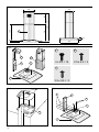
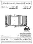
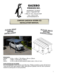
•Designer Island Hood
DIH900
Installation & User’s instructions
Fig.1
328
E
544
486
699 :
1074
530
284
58
64.5
600
Fig.2
I
B
E
C
F
G
4 x 9.5 = 14
2.9 x 9.5 = 2
P
A
Fig.3
3.5 x 9.5 = 3
Fig.4
Ø8
I
C
G
F
B
A
2
Fig.5
Fig.6
B
P
I
M
E
B
A
Fig.8
Fig.7
1A
P
A
B
C
D
E
F
1B
G
B
C
D
E
A
3
• Your new Belling Island Hood
Dear Customer
These instructions are designed to help you know your new cooker hood quickly and to
achieve the best possible results.
It is most important that this instruction book should be retained with the appliance for
future reference. Should the appliance be sold or transferred to another owner, or
should you move house and leave the appliance, always ensure that the book is
supplied with the appliance in order that the new owner can be acquainted with the
functioning of the appliance and the relevant warnings. Please ensure that you have
read the whole instruction book before using the appliance and that you follow the
recommendations.
Warnings
These warnings are provided in the interest of safety. Please read carefully before
installing or using the appliance.
1. Keep children away from the product.
2. Any installation work must be undertaken by a competent person and installed in
accordance with the current IEE regulations.
3. It is dangerous to alter the specification or modify the product in any way.
4. If this appliance is to be connected to a ventilation system, it should not be joined
with a ventilation system from any other appliance.
5. The product should be serviced by an authorised Belling service engineer and only
genuine Belling spare parts should be used.
• General information
This instruction book applies to various models and your model may not have all
functions described:
This cooker hood is guaranteed and will give lasting service. The guarantee is only
applicable if the hood has been installed in accordance with these instructions.
The cooker hood has been designed for use fixed directly to the ceiling.
The hood can be used to extract odours to the outside or to recirculate the air within the
kitchen after passing through a cleansing charcoal filter. Charcoal filters are supplied
as an optional extra, please phone Belling Spares department on 0844 815 3745 and
quote part number DCH900004.
The hood is convertible to either function.
Belling disclaims any liability for any damage or injury caused as a result of not
following the installation instructions.
Warning: This hood is designed for domestic use only.
When used in the extraction mode the cooker hood ducting must not be connected to a
flue which is used for exhausting fumes from appliances supplied with energy other
than electric, such as a central heating flue or a water heater flue.
If the room where the cooker hood is to be used contains a fuel burning appliance such
as a central heating boiler, then its flue must be of the room sealed or balanced flue
4
type. If other types of flue or appliances are fitted, ensure there is adequate ventilation
in the room.
All installations must comply with local authority requirements for the discharge of
exhaust air.
• Positioning
When installed above a cooking appliance the distance between the surface of the
appliance hotplate and the lower grill of the hood must not be less than 65cm (25½”).
This appliance is suitable for ceiling heights of approximately 236cm (7’9") and 273cm
(9’0") depending on the installation. If you have a ceiling greater than this height
please ring our spares department on 0844 815 3745 for the tall ceiling kit (see
Optional Extras).
If the cooker hood is installed for use above a gas appliance then the provision for
ventilation must be in accordance with the Gas Safety (Installation and Use)
Regulations and the relevant building regulations.
Warning: The fan motor of this cooker hood incorporates a thermal cut-out which will
operate if the cooker hood is installed below the minimum recommended height or the
motor overheats. If the cut-out operates. Switch off the cooker hood and allow the
motor to cool, the cutout will then reset itself.
• Unpacking
Care should be taken when unpacking the cooker hood to ensure that the following
parts are not discarded.
- Components
The hood consists of:
1 hood body A complete with controls and lights
1 upper mounting structure B.
1 lower mounting structure C.
1 complete telescopic flue E.
1 connecting flange F.
1 air deflector M.
1 bag containing:2 x G screws
14 x I screws
3 x P screws
Fixing template
Instructions and documents
• Installation Instructions
• Mounting the Cooker Hood
A) With the aid of the paper template placed with the arrow corresponding
to the cooker hood control side, mark the centre of the holes and drill 8
mm diameter (Fig.3)holes to suit location. Use 4 or more fixing holes according to the
location.
5
Note: Depending on the location and the construction of ceiling, it may be necessary
to use a more substantial method of fixing, e.g. nuts and bolts, rather than normal
self-tapping or wood screws.
B) Mount the connector flange F above the cooker hood ventilation kit,
using the G screws (Fig. 4).
Couple the lower mounting structure C with the cooker hood A using the 6
screws I (Fig. 4).
Connect a flexible air discharge tube (not supplied), of 120mm diameter, to the F
flange (Fig. 6)
Recirculating mode only : fix the air deflector M (fig. 6) to the upper mounting structure
B using the appropriate screw P.
C) Mount the cooker hood supporting the chimney flues and inserting
the lower mounting structure to the upper mounting structure, confirm the height and fix
the 2 structures together with the appropriate 8 screws I (fig. 5).
Recirculating mode only : connect the flexible tube previously mounted on the F
flange to the deflector M (fig. 6)
External exhaust mode : connect the discharge tube previously mounted to
the F flange to the external discharge pipe.
• Internal Exhausting
Charcoal filters are used to purify the air which will be recycled into the room. The filters
cannot be washed or regenerated and must be replaced every 4 months.
The charcoal filters are supplied as an optional extra, please phone Belling Spares
department on 0844 815 3745 and quote part number CHT28.
Saturation of the activated charcoal depends on more or less extensive use of the
hood, the type of kitchen and the regularity of cleaning the grease filter. The air is
recycled into the room through the slots in the flue E.
• Electrical Connection
Before connecting to the mains supply ensure that the voltage is as stated on the rating
plate inside the cooker hood.
Warning: This appliance is fully insulated and must not be earthed.
The appliance comes with a 2 core mains cable and should be permanently connected
to the electricity supply via a double pole switched fused spur outlet with a minimum
contact clearance of 3mm in both poles.
Installation must comply with the latest IEE regulations and must be carried out by a
competent person.
The cooker hood must be protected by a 3-amp fuse.
• Use and Maintenance
If your model has mechanical controls it is advisable to switch the cooker hood on a
few minutes before cooking starts and that it be left on for about 15 minutes after
cooking is completed to exhaust all the odours.
If your model has luminous controls, switch on a few minutes before cooking starts
and activate the automatic stop timer to allow the cooker hood to continue functioning
for about 15 minutes after cooking is completed to exhaust all the odours.
On the front of the hood there are (Fig. 8):
6
1A) LUMINOUS
A = LIGHT
B = OFF
C = SPEED I
D = SPEED II
E = SPEED III
F = AUTOMATIC STOP TIMER - 15 minutes
The “Automatic stop timer” allows the hood to continue functioning for 15 minutes at the
operating speed set at the time this function is activated.
1B) MECHANICAL
A = LIGHT
B = OFF
C = SPEED I
D = SPEED II
E = SPEED III
G= MOTOR WORKING indicator
Good functioning of the hood depends on the regularity with which maintenance
operations are carried out, in particular of the anti-grease filters and the activated
charcoal filter. The anti-grease filters have the function of holding back grease
particles suspended in the air, and are thus subject to clogging with time depending on
the frequency of use of the appliance.
Clean the filters every 2 months, carrying out the following operations:
- Remove the filters from the hood and wash them with warm soapy water.
- Rinse in abundant lukewarm water and leave them to dry.
- The filters may also be washed in the dishwasher.
The aluminium panels may be subject to colour alterations due to many washes. This
is natural over time and will not affect the performance of the appliance.
In case of inobservance of the washing instructions there is a risk of the filter catching
fire.
Frequently clean off all the deposits on the fan and other surfaces, using warm soapy
water.
• Replacement of the Halogen Lamp
WARNING!! DISCONNECT FROM MAINS BEFORE CHANGING LAMP
Note: The bulb is not covered by the guarantee as it is a consumable item.
Lamps are available from our spares department, please ring 0844 815 3745 and
quote part no.CHT265B
To replace the halogen lamp, carefully prise off the cover and remove complete with the
lamp glass.
Put in the new lamp taking care not to touch the glass with fingers and replace lamp
glass and cover.
• Do’s and Don’ts
Do take extra care when frying
Do clean grease filters and hood regularly
7
Do change charcoal filters regularly
Don’t leave naked flames under the cooker hood
Don’t leave frying pans unattended during use as overheated fat may catch fire
Don’t flambé cook under the cooker hood
Don’t try to check the filters when the hood is in operation.
Don’t touch the lamp after prolonged use of the appliance.
• If your cooker hood doesn’t work
Check the power supply
Is the hood switched on?
Has the hood become too hot and switched itself off?
If hood is still not working call for service
This appliance conforms to the following EEC directives
Low Voltage Directive
73/23/EEC
93/68/EEC
Electromagnetic Compatibility
89/336/EEC
92/31/EEC
93/68/EEC
8
• Optional extras
Please quote the following part number if you require a ducting or tall ceiling kit.
Filter
Ducting Kit Short
Ducting Kit Long
Tall ceiling kit Stainless Steel
Tall ceiling kit Aluminium
DCH900004
CHIM100004 (1m)
CHIM100004A (3m)
DIH900002
DIH900003
• Calling for Service
Please contact your retailer in the first instance. If you experience difficulty contact Belling
Appliances (After Sales Division)
Remember that you may be charged for the visit (even during the guarantee period) if
nothing is found to be wrong with the appliance, so always check the instructions in case
you have missed anything.
Belling Appliances After Sales Division (Service)
Tel: 08444 815 3746 (all calls will be charged at local rate)
Before contacting a service agent, please note the following details about your cooker:
Model Number
________________________________________________________
Serial Number
________________________________________________________
Date of Purchase
______________________________________________________
Also note your Postcode
________________________________________________________
In order to provide a complete service history for your cooker please ask the service engineer to record the appropriate details in the chart below.
Date
Nature of Fault
Parts replaced or repaired
Authorised stamp or
signature
9
10
11
Belling Appliances Ltd.
3LI0ISOMIRABE.1 - 03/05 -
Stoney Lane, Prescot, Merseyside L35 2XW
PART No. DIH900001/01/02