1
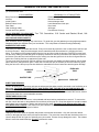
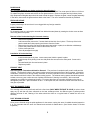
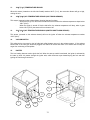
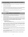
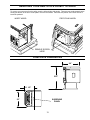
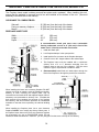
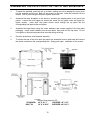
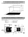
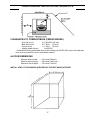
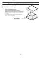
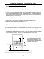
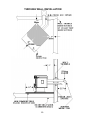
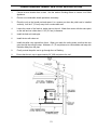
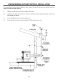
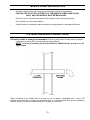
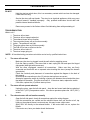
ENVIROFIRE
PELLET STOVE
EF-3 BAYi
OWNERS TECHNICAL MANUAL
MODELS FS, FPI and BIH
SHERWOOD INDUSTRIES LTD.
6782 OLDFIELD ROAD
VICTORIA, BRITISH COLUMBIA
V8M-2A3
1
ENVIROFIRE INSTALLATION MANUAL
TABLE OF CONTENTS
INTRODUCTION
Important Safety Data........................................................... 3
Pellet Quality ........................................................................ 4
Warnings and Recommendations......................................... 5
Automatic Safety Features ................................................... 5
OPERATION
How to Start Your Pellet Appliance....................................... 6
Turning Your Pellet Appliance Off ........................................ 6
Slider/Damper....................................................................... 7
SPECIFICATIONS
Areas for Routine Maintenance ......................................... 8-9
Electrical Component Functions .................................... 10-11
INSTALLATION
Deciding Where to Locate Your Pellet Appliance ............... 12
Vent Termination Requirements ......................................... 12
Removing Your New Stove From It’s Pallet........................ 13
Masonry Fireplace Insert Installation .................................. 14
Assembling the Face Plate for the FPI & BIH Models ........ 15
Model BIH Recommended Framing ................................... 16
Built In Heater Installation, Model BIH ................................ 16
Clearances and Alcove Clearances.................................... 17
Model FS (Freestanding) Installation.................................. 18
Horizontal Exhaust through the Wall ............................. 19-20
Freestanding inside Vertical Installation ............................. 21
Freestanding outside Vertical Pipe Installation ................... 22
Mobile Home Installation .................................................... 23
Outside Fresh Air Connections........................................... 23
Troubleshooting............................................................. 24-26
Wiring Diagram................................................................... 27
Warranty ............................................................................. 28
APRIL 1999
2
IMPORTANT SAFETY DATA
Please read this entire manual before installation and use of this pellet fuel burning room heater. Failure to follow
these instructions could result in property damage, bodily injury or even death.
CAUTION: DO NOT CONNECT OT ANY AIR DISTRIBUTION DUCT OR SYSTEM;
DO NOT BURN GARBAGE OR FLAMABLE FLUIDS SUCH AS GASOLINE, NAPTHA OR ENGINE
OIL;
HOT WHILE IN OPERATION. KEEP CHILDREN, CLOTHING AND FURNITURE AWAY.
CONTACT MAY CAUSE SKIN BURNS.
Contact local building officials about restrictions and installation inspection requirements in your area.
The stove’s exhaust system works with negative combustion chamber pressure and a slightly positive chimney
pressure, it is very important to ensure that the exhaust system be sealed and airtight.
The use of grates or other methods of supporting the fuel is not permitted.
This unit is designed to burn pelletized wood fuel only. Do not use any other type of fuel, this will void any
warranties stated in this manual.
THE USE OF CORDWOOD IS PROHIBITED BY LAW.
Do not burn with insufficient combustion air. A periodic check is recommended to ensure proper combustion air
is admitted to the combustion chamber. Setting the proper combustion air is achieved by adjusting the slide
damper located on the left side of the stove.
It is advisable to clean the exhaust vent bi-annually or every two tons of pellets.
The grounded electrical cord should be connected to a standard 230 volts, 50-hertz electrical outlet and also must
be accessible. If this power cord should become damaged a replacement power cord must be purchased from the
manufacture or a qualified ENVIROFIRE dealer. Be careful that the electrical cord is not trapped under the
appliance and that it is clear of any hot surfaces or sharp edges. This unit’s maximum power requirement is 520
watts.
Soot or creosote may accumulate when the stove is operated under incorrect conditions such as an extremely
rich burn (black tipped, lazy orange flames).
When installing the stove in a mobile home, it must be electrically grounded to the steel chassis of the home and
bolted to the floor. Make sure that the structural integrity of the home is maintained.
Be sure to maintain the structural integrity of home when passing a vent through walls, ceilings, or roofs.
The ash pan and viewing door must be locked securely for proper and safe operation of the pellet stove.
If you have any questions with regards to your stove or the above-mentioned information, please feel free to
contact your local dealer for further clarification and comments.
Since Sherwood Industries Ltd. has no control over the installation of your stove, we grant no warranty implied or
stated for the installation or maintenance of your stove, therefore, Sherwood Industries Ltd. assumes no
responsibility for any consequential damage.
SAVE THESE INSTRUCTIONS FOR FUTURE REFERENCE
3
PELLET QUALITY IS IMPORTANT,
PLEASE READ THE FOLLOWING PAGE
Your pellet stove has been designed to burn wood pellets only. Since there are many manufacturers of
wood pellets it is important to select pellets that are free of dirt or any impurities. The Pellet Fuel
Industries (P.F.I.) has established standards for wood pellet manufactures. We recommend the use of
pellets that meet or exceed these standards. Ask your dealer for a recommended pellet type.
THE PERFORMANCE OF YOUR PELLET STOVE IS GREATLY EFFECTED BY THE TYPE AND
QUALITY OF WOOD PELLETS BEING BURNED. AS THE HEAT OUTPUT OF VARIOUS QUALITY
WOOD PELLETS DIFFER, SO WILL THE PERFORMANCE AND HEAT OUTPUT OF THE PELLET
STOVE.
Since Sherwood Industries Ltd. has no control over the quality of pellets that you use, we assume no
liability caused by the quality of wood pellets used.
P.F.I. PELLET STANDARDS:
Fines ..................................... 1% maximum through a 1/8” screen
Bulk Density .......................... 40 lbs. per cubic foot minimum
Size ....................................... 1/4” to 3/8” diameter 1 – 1.5” long maximum
Ash Content .......................... 1% maximum
Moisture Content................... 8% maximum
Heat Content......................... approximately 8200 Btu per lb. minimum
Check the burn-pot liner periodically to ensure that the holes are not blocked with clinkers, (clinkers are
silica in the fuel that form a hard mass during the burning process). If they are blocked, remove the
liner (when the unit is cold) and clean the clinkers out. The liner should be cleaned or scraped once
every 2-3 days depending on wood pellet quality. Clean the holes in the lines with a small pointed
object.
Store pellets at least 36” (1 m) away from the pellet stove.
4
WARNINGS AND RECOMMENDATIONS
A.
Do not abuse the glass by striking or slamming the door shut.
B.
Do not attempt to operate the stove with broken glass.
C.
Do not attempt to open the door and clean the glass while the unit is in operation. If you must
clean the glass, use a soft cotton cloth and mild window cleaner.
D.
Do not use abrasive cleaners to clean the surface or any part of the stove.
E.
It is recommended that the unit be secured into its position in order to avoid any displacement.
F.
Never use gasoline, gasoline-type lantern fuel, kerosene, or similar liquids to start the fire. Keep
all such liquids well away from the pellet stove while it is in use.
G.
Disposal of ashes - Ashes should be placed in a metal container with a tight fitting lid. The
closed container of ashes should be on a non-combustible floor or on the ground, well away
from all combustible materials pending final disposal. If the ashes are disposed of by burial in
soil or otherwise locally dispersed, they should be retained in the closed container until all
cinders have thoroughly cooled.
H.
Make sure the ash pan is closed tightly during the operation of the stove.
I.
Fresh air intake is strongly recommended. Failure to install Intake air may result in improper
combustion as well as the unit smoking during power failures.
NOTE: Fresh air is mandatory on all units installed in “Mobile Homes” as well as “Air Tight”
homes.
J.
GOLD BARS: Please clean all fingerprints off of all gold parts before firing the unit each time.
Fingerprints etc. can become etched into the gold if not removed before operating the pellet
heater
K.
BRICK PANEL: The paint on the steel brick panel may peel, this is due to the extreme
conditions applied to the paint and is in no way covered under warranty.
AUTOMATIC SAFETY FEATURES OF YOUR PELLET STOVE
A.
The stove will shut off when the fire goes out and the exhaust temperature drops below 140°F
(60°C).
B.
The stove has a high temperature safety switch. If the temperature at the back of the firebox
reaches 200°F (93°C) the auger will automatically stop, and the stove will shut down when the
exhaust temperature cools. If this happens call your local dealer to reset the 200°F (93°C) high
limit switch. ALSO FIND THE REASONS WHY THE UNIT OVERHEATED.
C.
The unit has a convection fan control over-ride. This function causes the convection fan to
reach its full speed when the temperature at the back of the firebox reaches 160°F (71°C). This
is a normal safety feature of your unit. To compensate for the fan cycling action that may occur,
turn up the blower control proportionately to the heat output.
D.
If the power goes out, the unit will stop running. When the power comes back on, the stove will
not restart unless the exhaust temperature is still above 140°F (60 °C).
5
HOW TO START AND OPERATE YOUR PELLET APPLIANCE
1.
Check and
pellets.
fill
hopper
with
2.
Switch on power by pushing the
start up switch once only.
3.
Turn the Dial A Fire knob to the
12 o’clock position. (Lower
grade pellets may need a
higher setting on the feed
rate). NOTE: unit will take longer
to light if the hopper has been
completely emptied.
4.
Wait until the fire is established,
then turn knob “B” to the desired
heat output. (The stove may not
be able to burn in the BLUE
ZONE if poor quality wood pellets
are being used.) Adjust the Slider
Damper to the appropriate
setting.
5.
6
CONVECTION
BLOWER SPEED
CONTROL
AUGER LIGHT
START-UP
SWITCH
If the stove should shut off after
15 minutes and there is still a fire
in the firebox – press the start up
switch once more. If the fire
went out, return to step number 2
and re-light the stove.
DIAL-A-FIRE
HEAT
OUTPUT
KNOB
Adjusting the blower speed
control knob will vary the rate of
airflow into the room by varying
the speed of the convection
blower. *Note: The convection
blower may cycle to high automatically depending on the setting of the controls. This is a normal
safety feature of the unit.
TURNING YOUR PELLET STOVE OFF
To turn your stove off, simply turn the HEAT OUTPUT knob (knob “B”) counter-clockwise until the knob
clicks to the “off” position. This will stop the feed of pellets. The blowers will continue to run and cool
the stove. When cool enough the stove will shut down.
SPECIAL NOTES:
-
The flashing green light corresponds to the auger feed rate.
The scale on the Dial A Fire knob represents a range, not exact at times. Wood pellets of differing
quality may effect the performance of the stove. If the stove has trouble operating at the end of its
range, turn the heat output knob back slightly.
6
SLIDER/DAMPER INSTALLATION /OPERATION INSTRUCTIONS
This is used to regulate the airflow through the pellet stove.
INSTALLATION
1.
Remove the slider rod (short rod with knob and nuts) and the two nuts from their
package and open the left side panel.
2.
Remove the knob and outer nut from the knob. Push the rod through the hole in the
slider. Place the lock nut on the rod and tighten, leaving a 1/32’ gap between the slider
and one of the nuts.
3.
Make sure the slider moves freely. Close the side panel and tighten screws after placing
the rod through the panel. Screw the knob onto the slider.
OPERATION
-
On the low heat output settings, push the slider all the way in.
-
On the high heat output pull the slider out or until a good fire is achieved. A good
fire is in between a fire with lazy flames (and black tipped flames) and a forced fire
(very quick, shorter flames). A good fire is the most efficient and will have a bright
and active flame.
-
Hot magnetic reading 0.10 – 0.11
ON HIGH
Pull out until
an efficient
flame is
achieved
ON LOW
Push all the
way in
THE TUBE SCRAPER ROD: Put the stainless steel rod through the hole in the heat exchanger,
thread the rod into the scraper plate.
7
AREAS FOR ROUTINE INSPECTION
The following should be inspected periodically to ensure that the appliance is operating at its optimum and giving
you excellent heat value:
2-3 DAYS/WEEKLY
Burn Pot and Liner
Ash Pan
Inside Firebox
Behind Firebox Liners
Door Glass
Heat exchanger tubes
Ash pan and Door gaskets
SEASONALLY or 2 TONS OF FUEL
Exhaust Vent and Fresh Air Intake Tube
Blower Mechanisms
Heat exchanger tubes
Latch Mechanism of ash pan
Door Latch
All Hinges
Post Season Clean-up
TOOLS REQUIRED TO CLEAN UNIT: . Torx T-20 Screwdriver, 5/16 Socket and Ratchet, Brush, Soft
Cloth, Vacuum with fine filter bag
ASH PAN AND DOOR GASKETS
After excessive use the gasketing may come loose. To repair this, glue the gasketing on using high-temperature
fiberglass gasket glue available from your local dealer. This is important to maintain an airtight assembly.
BURNER POT AND LINER
This is the ‘pot’ where the pellets are burned. Every two to three days (when the unit is cold) remove the burn-pot
liner from the stove. Using a metal scrapper remove material that has accumulated or is clogging the liner’s
holes. Then dispose of the scrapped ashes from the liner and from inside the burn-pot. Place the burn-pot back
into the stove, making sure that the pipes are properly inserted into the burn pot and the front tabs are in place in
the firebox. Place the liner back into the burn-pot, making sure that the ignitor hole in the liner is aligned with the
ignitor tube. Pushing the liner up against the igniter tube.
To remove the burn pot and burn pot liner open the door using the door handle provided located on the left-hand
side of the stove, swing the door open. Lift the liner from the burn pot, lift the burn pot from the firebox by gently
lifting the front of the burn pot up first then sliding the assembly from the air intake tube and the igniter cartridge.
FRESH AIR
TUBE
BURN POT
LINER
IGNITER TUBE
BURN POT
INSERT ASH REMOVAL:
The EF 3Bi pellet stove insert does not have an ash pan and the ashes must be vacuumed out of the firebox on a
daily basis. CAUTION: BECAUSE THE FLY ASH IS VERY FINE, THE USE OF A VACUUM BAG WILL BE
REQUIRED TO PREVENT ASH FROM BEING BLOWN BACK INTO THE ROOM. Please pay special attention
that there are no hot ashes in the firebox or there could be a possibility of a fire hazard inside the vacuum cleaner.
Place all hot ashes into a noncombustible container.
FREESTANDING ASH PAN:
This part is located under the burner, in the pedestal and has a latching mechanism to secure it. To remove the
ash pan, unlock the latch on the pedestal cover and then pull the pan out. Dump the ashes into a metal container
stored away from combustibles. Monitor the ash level every week. Remember that different pellet fuels will
have different ash contents. Ash content is a good indication of fuel efficiency and quality. Refer to “Warnings
and Recommendations” for disposal of ashes.
BLOWER MECHANISMS
Unplug the stove then open the right/left side panels to access the two blowers. Only the convection blower
motor (on the right side of the stove) will require lubrication. The convection motor has two lubrication holes on it.
Use two drops of SAE 20, light oil to lubricate every six months. Excess oil may damage the motor. The exhaust
blower’s motor has sealed bearings, DO NOT lubricate this motor.
8
DOOR GLASS
(It is recommended that your dealer replace the glass if broken.)
The door glass is made of 5 mm thick, high temperature PYROCERAMIC The center panel is 229 mm x 330 mm.
To replace the glass, unscrew and remove the four glass retainers. Remove the glass and any broken pieces.
High temperature fiberglass tape should be used around the glass. Replace the glass, center the glass assembly
in the frame, then screw the glass retainers back to the frame. The use of substitute materials is prohibited.
FRESH AIR INTAKE
Inspect periodically to be sure that it is not clogged with any foreign materials.
INSIDE FIREBOX
For bi-weekly clean out, ash may be removed from behind the steel plates by rotating the circular cover to allow
vacuuming behind the plates.
Removal of the fire box backing for bi-annual cleaning
-
Remove the top baffle.
Lubricate and then remove the 7 screws that hold the brick liner in place. Tilt the top of the brick
panel towards the firebox opening and remove from the firebox
Remove the top rod by first removing the screw that holds it in place, then slide the rod sideways
Pull the side panels into the center of the firebox, then out
Pull the center panel out
Clean all passages thoroughly
Installation of fire box backing:
-
Install the side panels in place. Insert center panel, hold the panels in place
Install the top rod by sliding it into one side panel then across into the other panel. Screw rod in
place.
Re-install steel brick liner and screw in place.
Replace top baffle
EXHAUST VENT
Soot and Flyash: Formation and Need for Removal: - The products of combustion will contain small particles
of flyash. The flyash will collect in the exhaust venting system and restrict the flow of the flue gases. Incomplete
combustion, such as occurs during startup, shutdown, or incorrect operation of the room heater will lead to some
soot formation which will collect in the exhaust venting system. The exhaust venting system should be inspected
at least once every year or after two tons of pellets to determine if cleaning is necessary. We recommend
contacting your dealer for professional cleaning. To remove dust from the vent pipe, tap lightly on the pipe to
dislodge any loose ash. Open the bottom of the ”T” to dump the ash, then vacuum as much of the ash out of the
vent pipe as possible.
HEAT EXCHANGER TUBES
This cleaning rod is to be pulled back and forth a few times (ONLY WHEN THE UNIT IS COLD) in order to clean
away any fly ash that may have collected on the heat exchanger tubes. As different types of pellets produce
different amounts of ash, cleaning of the tubes should be done on a regular basis to enable the unit to run
efficiently.
POST SEASON CLEAN-UP
Once you are finished using the pellet appliance for the season, unplug the stove for added electrical protection.
It is very important that the stove be cleaned and serviced as stated above. (See Section Areas of Routine
Inspection)
9
ELECTRICAL COMPONENT FUNCTIONS
The following is a list of electrical components and their functions on the ENVIROFIRE EF-IIIi Bay pellet stove.
1.
CONVECTION FAN CONTROLLER
This controller is responsible for varying the speed of the convection blower. The stove does have a fan control
over-ride. Should the convection blower be set on low and dial-a-fire set on high, the convection blower will bypass the fan controller and go to high. This will cool the stove until control is given back to the fan controller. To
eliminate possible cycling of the convection blower turn up the fan speed proportionately to the dial-a-fire.
2.
AUGER PULSE LIGHT
This light will flash in conjunction with the pulses to the auger.
3.
START-UP SWITCH
When this momentary contact switch is pressed it will initiate a 15 minute start-up cycle including the ignitor.
4.
DIAL-A-FIRE (HEAT OUTPUT CONTROL)
This unit is responsible for controlling the timing of the auger motor. When turned clockwise it will cause the OFF
time between auger pulses to shorten, resulting in more heat output and pellet consumption. Turn the knob
counter-clockwise and the reverse will happen. When it is turned fully counter-clockwise past the click, the auger
motor will be off.
5.
CONVECTION BLOWER
This blower fan (mounted on the right side of the stove) draws room airs from the back of the stove and passes
the air through the heat exchanger tubes and back into the room. The units sealed system keeps the room air
separate from the combustion air. The convection fan controller controls this fan’s speed.
6.
EXHAUST/COMBUSTION BLOWER
This constant speed fan (mounted on the left side of the stove) is responsible for drawing the outside fresh air into
the combustion chamber for burning. The hot air then continues to be drawn over the heat exchanger tubes and
into the exhaust channel. It is then pushed out through the exhaust system.
7.
AUGER MOTOR AND AUGER
The 1 rpm auger motor is responsible for turning the auger, which in turn transports pellets to be dropped into the
burn pot. The auger motor’s control is handled by the timing control module and Dial-A-Fire.
8.
TIMING CONTROL MODULE
The timing control module is mounted uppermost, on the right rear pillar of the stove. The module controls the
switching of power to the auger. The module’s switching duty cycle is controlled by the dial-a-fire.
9.
START-UP TIMER
This 15 minute one-shot timer bypasses the 140°F (60°C) temperature sensor allowing the stove to operate when
cold. The timing cycle is initiated by pressing the start-up switch. The 15 minute timer is located right under the
timing control module on the right side pillar. This unit is also responsible for initiating the ignition cycle.
10.
200°F (93°C) MANUAL RESET TEMPERATURE SENSOR
This sensor (located on the right side firewall) has a red push button located in its center. This is a safety device.
In the event that the convection blower fails, this sensor will overheat and shut off power to the auger motor.
10
11.
160°F (71°C) TEMPERATURE SENSOR
When this sensor (located on the left side firewall) reaches 160°F (71°C), the convection blower will go to high,
cooling the unit.
12.
140°F (60°C) N/O TEMPERATURE SENSOR (SHUT-DOWN SENSOR)
This sensor (mounted on the exhaust blower housing) has two functions:
Should the fire go out, this sensor will shut the stove off when the exhaust temperature drops below
140°F (60°C).
When the auger is turned off via the dial-a-fire, the exhaust temperature will drop, when it goes
below 140°F (60°C) the sensor will turn the stove off.
13.
120°F (49°C) N/C TEMPERATURE SENSOR (IGNITOR SHUT DOWN SENSOR)
This sensor (mounted on the exhaust channel) will turn the ignitor off when the exhaust temperature reaches
120°F (49°C).
14.
VACUUM SWITCH
This safety device (mounted on the left side back pillar) detects vacuum in the exhaust system. If the exhaust
blower fails or the vent pipe becomes plugged, this switch will sense that there is no airflow and will stop the
auger from continuing to feed pellets.
15.
IGNITER
This is a heating element used to ignite the fuel. When the start up switch is activated, the igniter is activated by
the start up timer. Air passes through the igniter tube, which becomes super heated drying the fuel and then
igniting the fuel through convection.
8
10
5
11
9
6
7
12
13
14
11
DECIDING WHERE TO LOCATE YOUR PELLET APPLIANCE
1.
Check clearances to combustibles.
2.
Do not obtain combustion air from an attic, garage or any unventilated space. Combustion air may be
obtained from a ventilated crawlspace.
3.
Do not install the stove in a bedroom.
4.
You can vent the stove through an exterior wall behind the unit or connect it to an existing masonry or
metal chimney (must be lined if the chimney is over 6” in diameter, or over 28 sq. inches cross sectional
area). An interior vent can be used with approved pipe passing through the ceiling and roof.
5.
Locate the stove in a large and open room that is centrally located in the house. This will optimize heat
circulation.
6.
The power cord is 8 feet (2.43 m) long and may require a grounded extension cord to reach
the nearest electrical outlet.
VENT TERMINATION REQUIREMENTS
A.
Do not terminate the vent in any enclosed or semi-enclosed areas such as a carport, garage, attic,
crawlspace, narrow walkway, closely fenced area, under a sundeck or porch, or any location that can
build up a concentration of fumes such as stairwells, covered breezeway, etc.
B.
Vent surfaces can become hot enough to cause burns if touched by children. Non-combustible shielding
or guards may be required.
C.
Termination must exhaust above the inlet elevation. It is recommended that at least five feet of vertical
pipe be installed outside when the appliance is vented directly through a wall to create some natural draft
to prevent the possibility of smoke or odor during appliance shut down or power failure. To keep exhaust
from causing a nuisance or hazard from exposing people or shrubs to high temperatures. In any case,
the safest and preferred venting method is to extend the vent through the roof vertically.
D.
The vent terminal cannot be:
Less than 4 feet (1.2 m) below
Less than 4 feet (1.2 m) horizontally from, and
less than 1 foot (305 mm) above Doors, window openings, or gravity/ventilation air inlet into building:
E.
Distance from bottom termination and grade –12” (305 mm) minimum. This is conditional upon the plants
and nature of grade surface. The exhaust gases are hot enough to ignite grass, plants and shrubs
located in the vicinity of termination. The grade surface must not be lawn. Distance from bottom of
termination and public walkways is 7 feet (2.1 m) minimum.
F.
Distance to combustible materials is 2 feet (610 mm). This includes adjacent buildings, fences,
protruding parts of the structure, roof overhang, plants, shrubs, etc.
G.
When installing an FPI or BIH the chimney must be fully lined. Unless the chimneys inside diameter are
less than 6” around or has a cross section area of less than 28 square inches. We strongly recommend
lining all masonry chimneys.
H.
If the unit is incorrectly vented or the air to fuel mixture is out of balance, a slight discoloration of the
exterior of the house might occur. Since these factors are beyond Sherwood Industries Ltd.'s control, we
grant no guarantee against such incidents.
IT IS RECOMMENDED THAT ONLY AN AUTHORIZED DEALER INSTALL YOUR PELLET STOVE
12
REMOVING YOUR NEW STOVE FROM IT’S PALLET
To remove your new stove from its pallet, open the left and right side panels. There are two wood screws that are
holding the bottom of the stove to the pallet. Remove the screws. Close the side panels. See PAGE 18 how to
install the pedestal.
INSERT MODEL
FREE STAND MODEL
REMOVE SCREW
HERE
FIREPLACE DIMENSIONS
24”
30.5”
11 1/2”
SURROUND
PANEL
22”
13
MASONRY FIREPLACE INSERT INSTALLATION, MODEL FPI
The Fireplace Insert model includes surround face plates and a pedestal. When installing this unit,
ensure that the pedestal is removed from its box and installed on the bottom of the unit. (Surround
assembly instructions are in this manual).
CLEARANCE TO COMBUSTIBLES:
Side wall............................................8” (200 mm) from the body of the heater
Facing on masonry fireplace.............8” (200 mm) from the body of the heater
Mantle ...............................................8” (200 mm) from the body of the heater
FIREPLACE INSERT SIZE:
Width.................................................22”
Height................................................22 ¾”
Depth ................................................24”
(550 mm)
(570 mm)
(600 mm)
A noncombustible hearth pad must cover combustible
flooring underneath, as well as 6” (150 mm) in front of the
heater and 6” (150 mm) to the side of the heater
1. Install the hearth pad
2. Lock fireplace damper in the open position
3. Install positive flue connector at the fireplace dampers.
4. Connect a tee or 90-° degree elbow to the exhaust pipe
5. This fireplace insert must be installed with a continuous
chimney liner of 3 or 4” diameter extending from the
fireplace insert to the top of the chimney. The liner must
conform to type 3 requirements of CAN/ULC S635.
6. (Recommended) Install fresh air intake either through the
back of the fireplace or through the positive flue connector..
When installing the insert into a masonry fireplace DO NOT
remove any bricks or masonry, with the following exception;
Masonry or steel, including the damper plate, may be
removed from the smoke shelf and adjacent damper frame if
necessary to accommodate a chimney liner. Provided that
their removal will not weaken the structure of the fireplace
and chimney, and will not reduce protection for combustible
materials to less than that required by the national building
code.
When installing the fireplace insert into a zero clearance
fireplace, DO NOT cut or modify any factory firebox parts. If
the fireplace insert does not fit into a zero clearance fireplace
we recommend you use an ENVIROFIRE model FS and
install as a hearth mounted unit. Install a 3” (76 mm) flex pipe from the stove to the top of the chimney.
14
ASSEMBLING THE FACE PLATE FOR THE FPI AND BIH MODELS
1.
To attach the pedestal, place the unit on its back, making sure not to damage the wiring, then
bolt the pedestal onto the unit. Back off the screws on the base, install the pedestal over the
screws. Lock in place using the keyholes, tighten the screws.
2.
Assemble the three faceplates to the stove by screwing the hinged panels to the stove side
panels. Loosen the front hopper lid screws and center the top panel under the hopper lid,
tighten screws. Insert each side panel anchor screw through the top panel into the
corresponding side panel holes and tighten.
3.
Assemble the brass frame using the corner hardware and screws supplied in the face plate
packaging. Install corner hardware into the side brass, then push into the top frame. Do not
over-tighten or the side brass cannot be removed during servicing.
4.
Place the brass frame over the panel assembly.
5.
To access the rear of the stove after the panels are assembled remove side brass and remove
the anchor screws from the corresponding side. Swing panel open. Installation is the reverse.
Sizing of face plates for FPI:
STANDARD: 40” X 30 ¼”
OVERSIZE: 46” X 33”
BUILT IN:
36” X 32 9/16”
OVERSIZE: 46 X 34 ¾”
15
RECOMMENDED FRAMING FOR BUILT IN HEATER
When installing model BIH it is recommended that you use the dimensions shown in the diagram
below. These type of clearances will make it easy and readily accessible for service.
BUILT IN HEATER CLEARANCES TO COMBUSTIBLES
This unit includes a 3” (75 mm) pedestal and surrounding faceplates. The part of the unit behind the
faceplate can be enclosed with combustible material. Model BIH has 1” (25 mm) standoffs to establish
clearances to combustibles to the back, top and sides. The minimum clearances and the size of the
enclosure are as follows:
-Sides and Rear ....................I- 0 INCHES (to standoffs)
-Depth ...................................J- 11 INCHES (275 mm)
-Side wall to unit.................... - 8 INCHES (200 mm
Mantle to unit .......................L- 8 INCHES (200 mm)
16
FREESTANDING INSTALLATION, MODELS FS
CLEARANCES TO COMBUSTIBLES (FREESTANDING)
- Side wall to unit
A- 6 INCHES (150 mm)
- Back wall to unit
B- 1 INCH
(25 mm)
- Corner to unit
C- 1 INCH
(25 mm)
- Mantle (Hearth Mount)
8 INCHES (
- Combustible flooring underneath the unit and extending 6 INCHES (150 mm) to the sides and
front must be protected by a non combustible material.
ALCOVE DIMENSIONS
Minimum Alcove width...........36 inches (900 mm)
Minimum Alcove height .........48 inches (1200 mm)
Maximum Alcove depth .........30 inches (750 mm)
INSTALL VENT AT CLEARANCES SPECIFIED BY THE VENT MANUFACTURER.
17
MODEL FS (FREESTANDING) INSTALLATION
PEDESTAL INSTALLATION:
Model FS comes with a pedestal that has to be attached prior to
installation:
-
Remove the pedestal from the box
Remove the ENVIROFIRE heater form the box.
Place the unit on its back, making sure not to damage the
wiring.
Back off the screws on the base, install the pedestal over
the screws.
Lock pedestal in place using the keyholes, tighten the
screws. Return unit to upright.
INSTALLATION
KEYHOLES HERE
18
HORIZONTAL EXHAUST THROUGH THE WALL
1. NOTE: Use only listed type “PL” or “L” pellet venting products. Failure to use listed components may cause
damage or personal injury or death.
2. Choose a location for your stove that meets the requirements stated in this manual and allows installation with
the least amount of interference to house framing, plumbing, wiring, etc.
3. Install a non-combustible hearth pad underneath the unit extending 6 inches (15 cm) in front of and to
the sides.
4.
Place the stove 15” (37.5 cm) away from the wall. If the stove is to be set on a hearth pad, set the unit on it.
5. Locate the center of the exhaust pipe on the stove. Extend that line to the wall. Once you have located the
center point on the wall, use a hole saw to cut a 7” (175 mm) diameter hole for a 3” (76 mm) vent pipe or an
8” (200 mm) hole for a 4” (101 mm) vent pipe.
6. Install the wall thimble as per the instructions written on the thimble. Maintain an effective vapor barrier
7. Install a 2 or 3’ (61 or 92 cm) length of 3” (76 mm) or 4” (101 mm) listed type “PL” or “L” vent pipe into the
wall thimble. The pipe should install easily into the thimble.
8. Install the fresh air intake (see the section entitled OUTSIDE FRESH AIR CONNECTIONS).
9. Connect the exhaust vent pipe to the exhaust pipe on the stove.
10. All Joints in the vent system shall be fastened with (3) three screws. Seal the connection with high
temperature silicone
11. Push the stove straight back, leaving a minimum of 1” (3 cm) clearance from the back of the stove to the wall.
Seal the vent pipe to the thimble with high temperature silicone.
12. The pipe must extend at least 12’ (30 cm) away from the building. If necessary, bring another length of pipe
(PL type) to the outside of the home to connect to the first section. Do not forget to place high temperature
silicone around the pipe that passes through the thimble.
13. Install a vertical pipe, or if all requirements for direct venting are met, install vent termination. The stainless
steel cap termination manufactured by the vent manufacturer is recommended. However, when the vent
terminates several feet above ground level and there are no trees, plants, etc. within several feet, a 45 degree
elbow can be used as termination. The elbow must be turned down to prevent rain from entering.
NOTE: Some horizontal, through the wall
installations may require a “T” and 4-5 feet of
vertical pipe outside the building to help draft
the stove. This may be required if a proper
burn cannot be maintained, after the stove
has been tested and the airflow set. This is
due to back-pressure in the exhaust, caused
by the air flow around the house.
5.0”
16.625”
10.812”
11.938”
19
THROUGH WALL INSTALLATION
1”
20
FREESTANDING INSIDE VERTICAL INSTALLATION
1.
Choose a stove location that is ideal. See the section Deciding Where to Locate Your Pellet
Appliance.
2.
Place a non-combustible hearth pad where necessary.
3.
Place the unit on the hearth pad and space it in a manner so when the pellet vent is installed
vertically, it will be 3” (76 mm) away from a combustible wall.
4.
Locate the center of the fresh air intake pipe on the unit. Match that center with the same point
on the wall and cut a hole about 1 5/8” (41 mm) in diameter.
5.
Install the fresh air intake pipe.
6.
Install the tee with clean out.
7.
Install the pellet vent upward from there. When you reach the ceiling make sure that the vent
goes through the ceiling firestop. Maintain a 3” (76 mm) distance to combustibles and keep attic
insulation away from the pipe.
8.
Finally, extend the pellet vent to go through the roof flashing.
9.
Ensure that the rain cap is approximately 36” (900 mm) above the roof.
21
FREESTANDING OUTSIDE VERTICAL INSTALLATION
To accomplish the above titled installation, follow steps 1 through 8 in the previous section and then
finish it by performing the following.
9.
Install a tee with clean out on the outside of the house.
10.
Install PL vent upward from the tee. Make sure that you install support brackets to keep the
vent straight and secure.
11.
Secure the flashing as you go through the roof.
12.
Ensure that the rain cap is approximately 36” (900 mm) above the roof.
1”
22
MOBILE HOME INSTALLATION
-
Secure the heater to the floor using the two bolt holes supplied in the pedestal.
-
CAUTION: THE STUCTURAL INTEGRITY OF THE MANUFACTURED HOME FLOOR,
WALL, AND CEILING/ROOF MUST BE MAINTAINED.
-
Ensure the unit is electrically grounded to the chassis of your home (permanently).
-
Do not install in a room people sleep in.
-
Outside fresh air is mandatory when installing into airtight homes or manufactured homes.
OUTSIDE FRESH AIR CONNECTIONS
A Fresh air intake is strongly recommended. Failure to install Intake air may result in improper
combustion as well as the unit smoking during power failures.
NOTE: Fresh air is mandatory on all units installed in “Mobile Homes” as well as in “Air
Tight” homes.
When connecting to an outside fresh air source, do not use plastic, combustible pipe. Only 1 5/8”
diameter steel, aluminum or copper pipe should be used. It is recommended, when you are installing a
fresh air system, to keep the number of bends in the pipe to a minimum.
23
TROUBLESHOOTING
DO NOT:
-
Hold the start-up switch down, this is a momentary contact switch and can be damaged
if held down too long.
-
Service the stove with wet hands. The stove is an electrical appliance, which may pose
a shock hazard if handled improperly. Only qualified technicians should deal with
possible internal electrical failures.
-
Remove any screws in the firebox without first lubricating them with penetrating oil.
TROUBLESHOOTING:
What to do if:
1.
2.
3.
4.
5.
6.
7.
8.
9.
The stove will not start
The stove will not operate when hot
The exhaust blower will not function
The convection blower will not function normally
Igniter , The pellets will not light.
The auger motor does not function normally
The Dial-A-Fire has no effect on the fire
The stove will not shut off
The stove keeps going out
*NOTE: All troubleshooting procedures should be carried out by qualified technicians.
1.
The stove will not start
-
2.
The stove will not operate when hot
-
3.
Make sure the stove is plugged in and the wall outlet is supplying power.
Push the Start-up switch, if the stove fails to start, unplug the unit and open the hinged
side panels (held tight with two screws).
With the stove unplugged, examine all connections. Make sure they are firmly
connected and that there are no exposed wires touching the stove (except the chassis
ground wire).
Check the continuity and placement of connections against the diagram in the back of
this manual.
Ensure that the connections to the (15) minute start-up timer are correct.
Attempt to bypass the switch by inserting a jumper wire between the red and white wires
that attach to the switch. Plug the stove back in. If the stove starts, replace the switch.
If this fails, replace the (15) minute start-up timer.
Unplug the stove, open the left side panel. Jump the two brown leads that are attached
to the 140°F (60°C) temperature sensor. If the stove operates replace the 140°F (60°C)
sensor.
The exhaust motor will not function normally
-
Open the left side panel, check all connections against the wiring diagram.
If all the connections are verified and the exhaust blower does not function at all, tap
lightly on the exhaust blower’s motor end cap, this may loosen a tight motor.
Apply 230V AC directly to the exhaust blower. If the motor does not run, replace the
blower.
If the motor runs, have your dealer check the harness.
24
4.
The convection blower will not function normally
-
5.
Check all the connections between the controller, switch, and the convection blower
against the wiring diagram.
If the convection motor will not run, apply 230V AC to the motor directly. If the motor
runs, replace the fan controller. If the motor does not run, the convection blower has
failed. Replace the blower.
If the convection blower runs on high at all times (no control with the fan controller),
check the connections from the 160°F (71°C) sensor (located on the upper left side of
the firewall) and convection fan controller to the blower. Disconnect one of the wires
from the sensor, if control of the convection blower returns to the fan controller, replace
the sensor.
If the motor is still on high, re-connect the sensor and replace the convection fan
controller.
Igniter- the pellets will not light
-
Everything else in the stove operates but the igniter will not light the pellets
Check all the electrical connections on the 120°F (49°C) temperature sensor located on
the exhaust channel.
Check the connections at the igniter socket.
Place a jumper wire between the two leads on the 120°F (49°C) temperature sensor. If
the igniter works. Replace the sensor.
If the igniter does not work. Replace the igniter
NOTE: The igniter should be a bright yellow or bright orange in color. If not Replace the igniter.
6.
The auger motor will not function normally
-
Make sure the exhaust blower is operating.
Make sure the dial-a-fire is turned on.
Unplug the stove and open the side and back panels.
Check all the connections to the auger motor, auger dial-a-fire, vacuum sensor, 200°F
(93°C) temperature sensor and the timing control module against the wiring diagram in
this manual.
Check the condition of the vacuum hose (located on the left side of the stove). It should
not be cracked or torn and should be installed on the top air inlet tube on the vacuum
sensor.
Check the manual reset button on the 200°F (93°C) temperature sensor. If this sensor
has been tripped, check for the cause of the over-heating before pushing the red button
in. Check auger for movement.
If the auger still does not work, then apply 230V ACdirectly to the auger motor. If the
auger motor does not work, replace it.
By-pass the 200°F (93°C) temperature sensor with a jumper wire check the auger. If the
auger works replace the sensor.
Check the voltage across the load pins of the timing module. It should be around 1-2 V,
cycling to line voltage during an auger pulse. If not, replace the timing control module.
Check the vacuum sensor by placing a jumper wire between the blue wire and the black
wire that are attached to the sensor. If the auger works, test to see if the exhaust blower
is producing enough vacuum.
To test the exhaust vacuum place a magnehelic gauge in the sensor end of the vacuum
tube. It should read 0.5wc”. If the reading is good then replace the vacuum sensor.
If the auger motor still does not work, then attempt to by-pass the auger dial-a-fire
control by removing the leads from the timing control module’s second delay pins and
25
7.
placing a jumper across the pins. If the auger now cycles very quickly, test the dial-a-fire
potentiometer. If the auger did not cycle then replace the timing control module.
To test the dial-a-fire potentiometer. The potentiometer should have a range of 68K to
approximately 850 K (± 10%), if the range is not close then replace the potentiometer.
The dial-a-fire has no effect on the fire
-
Make sure all connections to the timer control module are secure.
Perform a resistance test to the dial-a-fire potentiometer, by placing the two test leads
from a multimeter into the leads of the potentiometer. The potentiometer should have a
range of 68K to approximately 850 K (± 10%).
Potentiometer Readings:
Full counter-clockwise (switched off) = open circuit, overload or Infinite resistance
Low fire...................... 800 K to 900 K
High fire..................... 68 K to 82 K
If the range is not close or does not vary then replace the potentiometer.
8.
The stove will not shut down
-
9.
Check the connections to the 140°F (60°C) temperature sensor, start-up switch and the
start-up timer against the wiring diagram.
Check the 140°F (60°C) temperature sensor by removing one of the brown wires from
the sensor. The unit should shut down right away as long as the start button was not
pressed within 15 minutes of this test. If the stove shuts down within 15 minutes,
replace the 140°F (60°C) sensor. If the stove does not shut down within 15 minutes, test
the switch.
To test the switch, the stove must be cold. Pull the plug, then plug the stove back in. If
the fails to start, Replace the switch.
The stove keeps going out
-
If the stove goes out and leaves fresh un-burned pellets or cigarette-like ashes in the
burn pot liner, the fire is going out before the 140°F (60°C) temperature sensor shuts the
stove off.
Check to see that the slider is in the correct position.
Turn the Dial-a-Fire up slightly (poor quality pellets will require slightly higher
settings).
-
If the stove goes out and there are partially burned pellets left in the burn pot liner, the
stove shuts down due to a lack of air, exhaust temperature or power failure.
Adjust the slider damper.
Check to see if the stove needs a more complete cleaning.
Turn the Dial-a-Fire up slightly (poor quality pellets will require slightly higher
settings).
Did the power go out?
-
If the stove goes out and there are no pellets in the liner, the auger is stopping.
See “The auger motor will not function normally” and “The exhaust blower will not
function normally.”
26
WIRING DIAGRAM
27
WARRANTY
Sherwood Industries Ltd. gives a five year limited warranty on all steel manufactured parts. A one year warranty
is provided on all electrical components. The above limited warranties are extended only to the original
purchaser.
There is no warranty on the following parts:
-
Glass window
Fiberglass rope baskets
Refractory material
Burn pot liner
Paint
Enamel finish or gold plating where it applies, and,
Vacuum hose.
**NOTE: The paint on the brick firebox lining may peel, this is due to the extreme
conditions applied to the paint and is in no way covered under warranty.
All claims forwarded under this warranty shall be made in writing to:
6782 Oldfield Road
Saanichton, British Columbia, Canada
V8M-2A3
When filing a warranty claim please quote the following:
-
Name and address of dealer,
Date of purchase
Name, address and telephone number of purchaser
Name, address and telephone number of installer
Date of installation, and
Serial number of the appliance
ENSURE THAT YOU SPECIFY THE NATURE OF THE COMPLAINT, DEFECT,
PERIODICAL MALFUNCTION, ETC.
The limited warranty covers defects in materials and workmanship as long as the products has been installed
according to the manual’s instruction. If the product is damaged or broken as a result of mishandling or misuse,
the warranty does not apply. Removal and re-installation costs are not covered under this warranty.
It is the manufacturer’s option whether to repair or replace the appliance. The shipping cost to and from the
factory is to be paid by the consumer. All warranties by the manufacturer are set forth herein and no claim shall
be made against the manufacturer on any oral warranty or representation.
Sherwood Industries Ltd. assumes no responsibility for damage caused by household power fluctuations or power
surges.
Under Warranty
For the do-it-yourself Individual
The consumer should be aware that the pellet appliance needs setting using tools that he/she might not have.
Consult an ENVIROFIRE dealer. It is recommended than only an authorized ENVIROFIRE dealer installs an
ENVIROFIRE unit. There will be no warranty coverage on parts destroyed or burnt out as a result of a consumer
installation error or defect.
Sherwood Industries Ltd. reserves the right to make changes without any
notice.
E-MAIL ADDRESS ( [email protected] )
WEB SITE ADDRESS ( http//cvcprod.ca/sherwood )
28